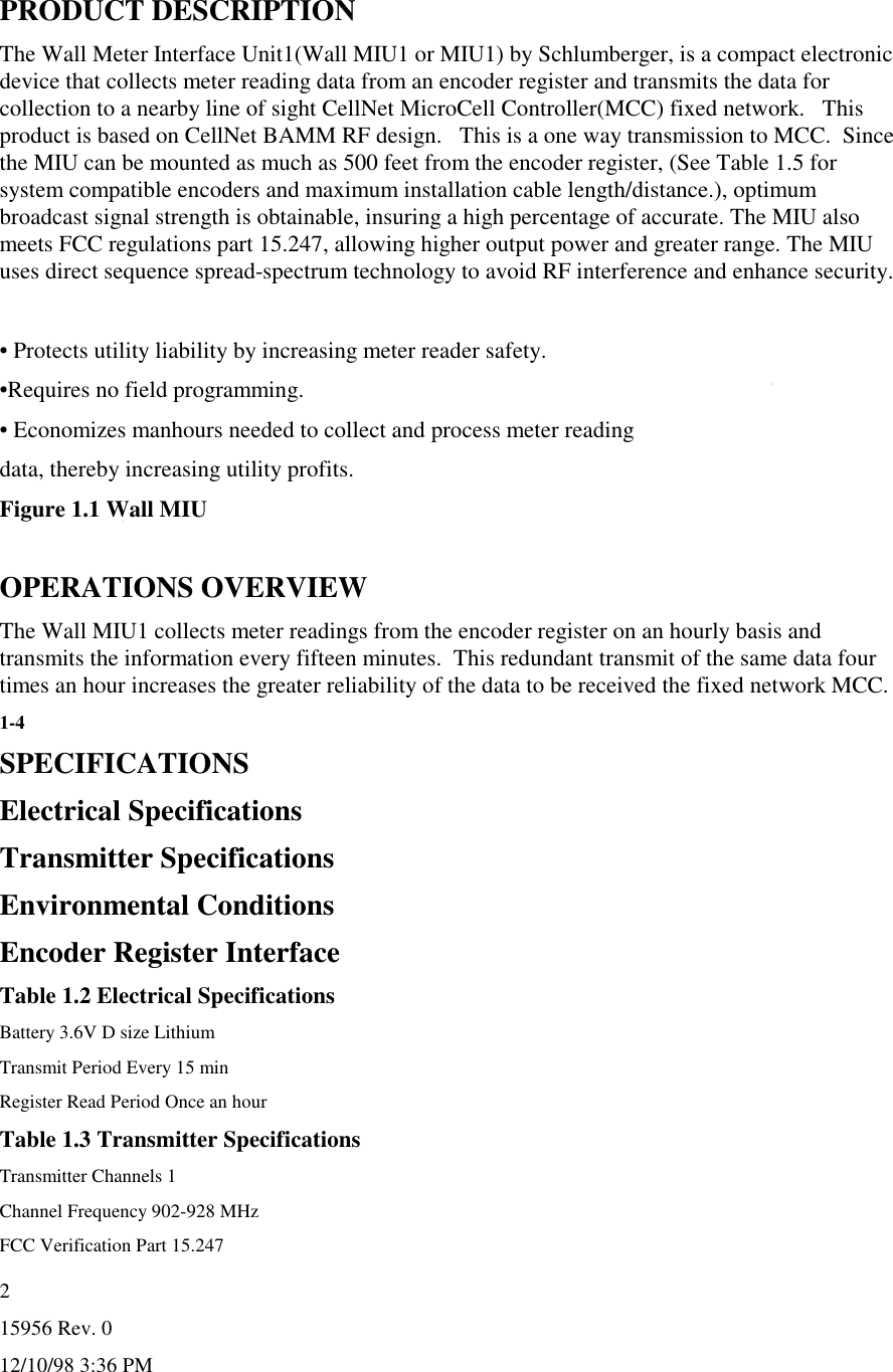
Schlumberger Sema TALWCNMIU1 Water Meter Spread Spectrum Transmitter User Manual
Schlumberger Sema Water Meter Spread Spectrum Transmitter Users Manual
UserManual.wiki
>
Schlumberger Sema
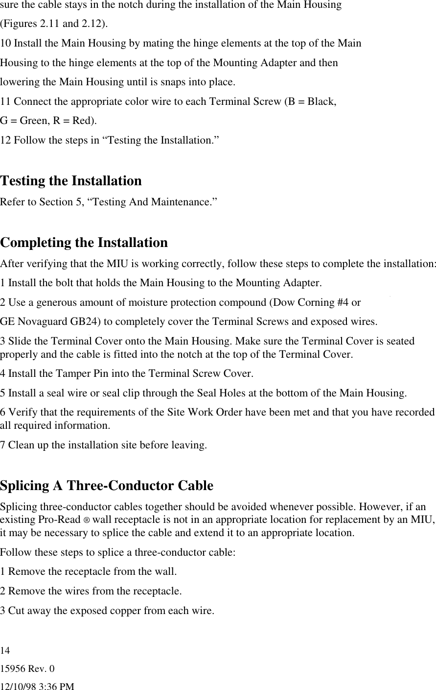
>
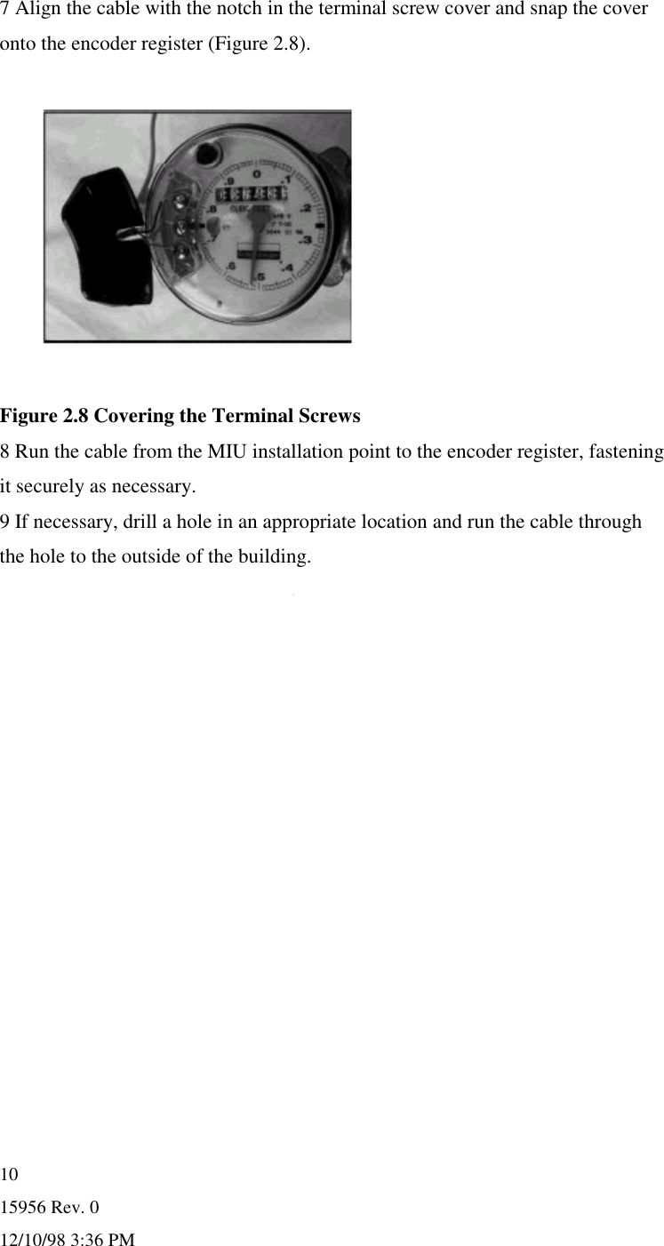
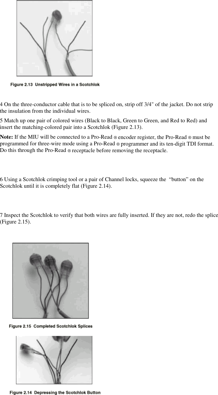
TALWCNMIU1 User Manual
Users Manual
Navigation menu
Upload a User Manual
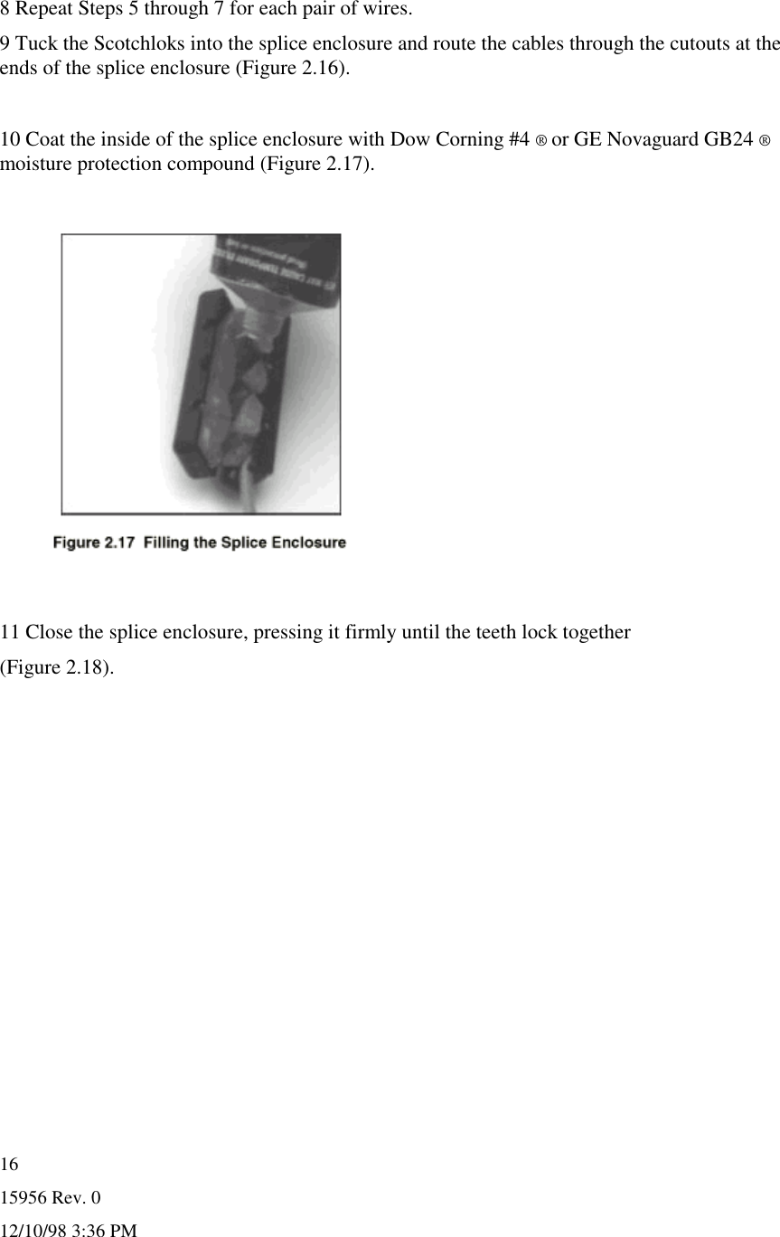
Namespaces
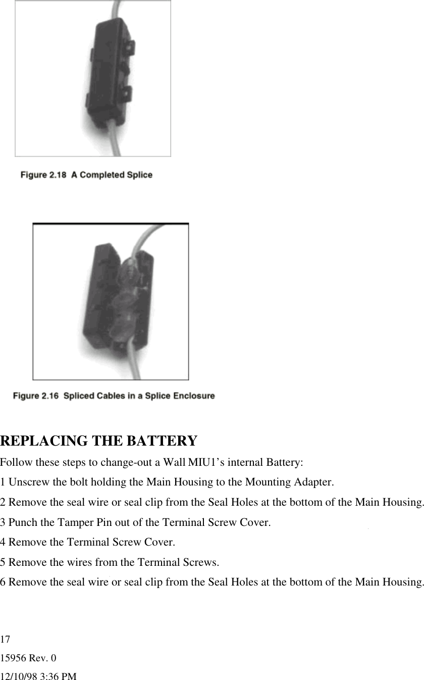
Wiki Guide
HTML
PDF
Info
Views
User Manual
Discussion / Help
Navigation