Schneider Electric Buildings WIRELESS Wireless Adapter User Manual Manual
Schneider Electric Buildings LLC Wireless Adapter Manual
Manual
Installation Instructions
Wireless Adapter/Repeater
© 2006 TAC / Tour Andover Controls, Inc., all rights reserved.
Introduction
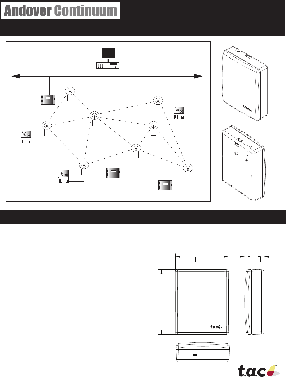
TAC has designed a device that allows Andover Con-
tinuum controllers to communicate with other controllers
across a wireless eld bus mesh network. The Andover
Continuum Wireless Adapter/Repeater is a single device
that can perform two roles — adapter and repeater.
As a Wireless Adapter, the device is attached to the
service port of a controller and allows the controller
to communicate across a wireless mesh network with
other controllers. The Wireless Adapter replaces the
normal hard-wired network connection between control-
lers. Power to the Adapter is supplied by the controller,
through the service port.
As a Wireless Repeater, the device is used to strength-
en the mesh network by providing redundant routes
to circumvent temporary or permanent obstructions. A
robust mesh network is able to self heal by dynamically
creating optimal routes. A Repeater may be needed
when there are long distances between wireless-en-
abled controllers, or to compensate for obstructions,
such as pipes or walls that can attenuate or weaken the
wireless signal between controllers.
When the device is used as a wireless repeater, it is not
connected to a controller, can be installed almost anywhere,
and only requires a power source to function.
i2/b3 Controller
i2/b3 Controller
i2/b3 Controller
i2/b3 Controller
i2/b3 Controller
bCX Controller
Wireless
Repeater
Wireless
Repeater
Wireless
Adapter
Wireless
Adapter
Wireless
Adapter
Wireless
Adapter
Wireless
Adapter
Ethernet
Workstation
Wireless
Adapter
.79
20
2.16
55
2.63
67
30-3001-887
Rev A
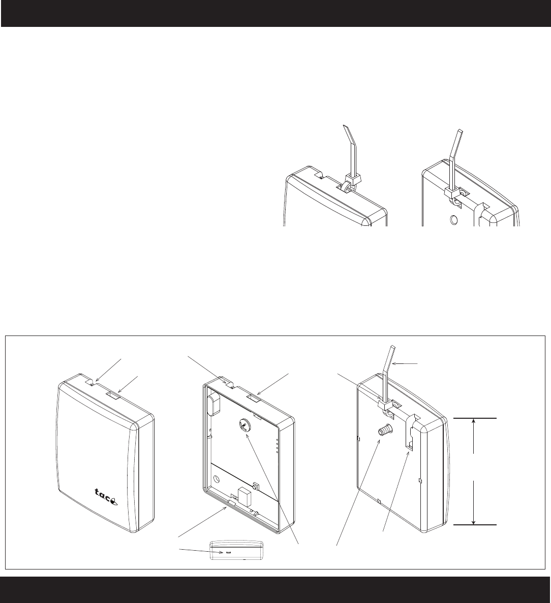
Wireless Adapter/Repeater Installation Steps
To install on a wall:
1) Locate an appropriate area to install the unit.
2) Locate the cover latch on the bottom of the unit and
use a small screwdriver to squeeze the latch and
and remove the cover from the unit.
Note: The PC board is exposed. Handle with care to prevent
damage to the components by electostatic discharge.
3) Place the unit in position. Mark the location of the
mounting hole.
4) Use a drill to create a small pilot hole for a #6
(3.5mm) mounting screw, or for the wall anchor, if
necessary. (Screw and wall anchor are provided.)
5) Insert the #6 mounting screw through the unit and
into the wall, being careful not to over tighten and
damage the electronics.
6) Snap the cover back in place.
Note: The wireless adapter may be positioned so the cable
comes out the top or bottom of the device. The cover
can be installed in either direction.
To hang vertically from a ceiling or object:
1) Make sure the unit is closed.
2) Insert a tywrap, wire, or thin cord through the
mounting recess located in the top center of the
unit.
Cover Latch
RS-485 Cable Outlet
Mounting Recess
Mounting Screw
Cable Outlet
Mounting Recess
Front Inside Back
Long axis should be
vertical for optimum
performance
Optional tywrap for hanging
device vertically
Installation Notes
1) Install the Adapter/Repeater with the long axis vertical for optimum performance.
2) Install away from metal or water-filled objects. These objects block or diminish the signal.
3) Install at a horizontal plane height where there are as few objects as possible. For example, in an office with cubicles, install the
units two feet or so above the average cubicle wall height. This placement allows the adapters/repeaters to transmit across a
horizontal plane that does not contain a lot of objects that can potentially block or diminish the signal.
4) Once installed, select a channel that is not normally used by other wireless applications. The default channel is 3, but you can
reset the channel using the Andover Continuum Wireless Maintenance Tool. (Note: The frequencies of the TAC Wireless Adapter
(802.15.4) channels do not line-up with Wi-Fi (802.11) channels. For example, TAC channel 3 is between Wi-Fi channels 1
and 2.)
3) Secure the unit, fastening the tywrap, wire, or thin
cord over, through, or around the mounting object.
( i.e., eyehook, exposed screw, pipe, ceiling support, etc.)
4) Make sure the unit is secure.
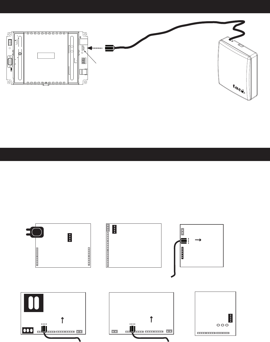
Connecting the Adapter to a Controller
CPU
INFINET (YELLOW)
BACNET (GREEN)
RESTART
COMM
PORT 1
RS-232
(DTE)
N ( )
L ( )
INPUT POWER
24 VAC
40 VA
50/60 HZ
12-28 VDC
25W
xP EXP
PORT
24VDC
400mA
DCD
RTS
RD
TD
RD
TD
SHLD
SERVICE
C
O
M
M
P
O
R
T
2
PORT
RS-485
ETHERNET
10/100
BASE T
RS 232
LINK/ACT
10/100
Mbps
Controller RS- 485 Service Port
Supplied 6 foot cable
* Adapters with 25 foot
cables are also available
Wireless
Adapter
1) Connect the Wireless Adapter to a controller’s service port using the RS-485 4-pin connector.
2) The controller will automatically recognize (“learn”) the other wireless devices on the wireless field bus (mesh network).
Notes: On the bCX fieldbus, you must set the default mode of COMM2 to “Wireless.”
A learn will discover wireless i2/b3 controllers that are properly configured
Controllers with Hidden Service Port Connections
On most Andover Continuum controllers, the service port connection is located outside the cover and labelled appropriately. How-
ever, there are a few controllers where the service port connections are only accessable by removing the controller covers.
The following illustration lists the controllers with internal service ports and identifies their approximate location on the controller
circuit boards. Some of the controllers have service port connectors, so the correct pin orientation is guaranteed. For controllers that
only have the four individual service port pins, the following illustration shows the correct orientaton of the Wireless Adapter cable’s
connector, using the location of the connector’s raised tab.
Service Port
Connector
i2/b3 865/866/885-V Controller
Service Port
Connector
i2/b3 865/866 VAV Controller
Service Port
Pins
i2/b3 885 VAV Controller
Connector Tab
i2/b3 887- L Controller
Service Port
Pins Service Port Pins
i2/b3 887 Controller i2/b3 867 Controller
Service Port
Connector
Controller Circuit Board Locations of Service Port Connector or Pins
Connector Tab Connector Tab
Specifications
Environment
Standard Operating Temperatures
-40 to 185 degrees F (-40 to 85 degrees C)
Storage Temperature
-40 to 185 degrees F (-40 to 85 degrees C)
Humidity (non-condensing)
0 to 95%
Power Requirements
Wireless Adapter
Power = 3.3 volts +/- 5% @ 75 mA
Supplied by the controller via the service port connection.
Wireless Repeater
Power = 3.3 VDC to 5 VDC +/- 5% @ 75 mA
Supplied by a 3.3 VDC to 5 VDC power supply.
Wireless Communications
Frequency Range
16 Software selectable channels
2405 MHz to 2480 MHz, 5 MHz channel spacing
Modulation Type
O-QPSK Direct Sequence Spread Spectrum (DSSS) per
IEEE 802.15.4 standard
Output Power
0 to +10dBm typical
Software selectable
Speed
250 Kbps
Transmission Range
200 meters (650 feet) Outdoors Line of Sight
10 to 60 meters (30 to 200 feet) indoor range
Distances vary based on environmental conditions
Antenna
Internal
Connection
RS-485 Speed: 38.4K to 50K baud
RS-485 Connector: Four pins (two pins data, one power, one
ground)
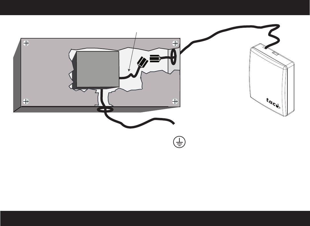
Connecting the Repeater to a Power Supply
1) Connect the attached Wireless Adapter/Repeater cable to the power supply adapter cable.
2) Connect the power supply adapter cable to the power supply.
Note: The power supply is not part of the Wireless Adapter/Repeater and is sold separately.
Wireless
Repeater
To AC Power Source
Earth GND Connection
Customer-Supplied Enclosure
Power Supply
Adapter Cable
3.3 VDC
C-Tick (Australian Communications
Authority (ACA))
AS/NZS 3548
This equipment carries the C-Tick label and complies with
EMC and radio communications regulations of the Australian
Communications Authority (ACA), governing the Australian
and New Zealand (AS/NZS) communities.
WEEE - Directive of the European Union
(EU)
This equipment and its packaging carry the waste of electrical
and electronic equipment (WEEE) label, in compliance with
European Union (EU) Directive 2002/96/EC, governing the
disposal and recycling of electrical and electronic equipment in
the European community.
Regulatory Notices
Federal Communications Commission
FCC Rules and Regulations CFR 47, Part 15, Class C
This device complies with part 15 of the FCC Rules. Operation
is subject to the following two conditions: (1) This device may
not cause harmful interference, and (2) this device must accept
any interference received, including interference that may cause
undesired operation.
Caution: The user that changes or makes modifications not
expressly approved by Tour Andover Controls, Inc. for compli-
ance could void the user’s authority to operate the equipment.
FCC ID: DVE-WIRELESS
This product meets FCC Radiation Exposure requirements.
Make sure to install and operate the device in such a way as to
maintain a minimum of 20cm separation distance between the
device and a person’s body.
Industry Canada Radio Equipment
IC RSS 210 Industry Canada
This digital apparatus does not exceed the wireless require-
ments for Industry Canada IC RSS-210 and is listed on the
Industry Canada Radio Equipment List.
IC: 1026A-WIRE
CE - Compliance to European Union
(EU)
89/336/EEC - EMC Directive
EN300328/EN30149, EMC - Radio Spectrum Matters
This equipment complies with the rules of the Official Journal
of the European Communities specified in the EMC directive
89/336/EEC governing the Self Declaration of the CE Marking
for the European Union.

TAC / Tour Andover Controls, Inc.
One High Street
North Andover, MA 01845
(978) 470-0555
Fax: (978) 975-9782
http://www.tac.com