Schneider Electric France L Isle d Espagnac XCSR Tag Reader User Manual
Schneider Electric Industries France L'Isle d'Espagnac Tag Reader
UserManual.wiki
>
Schneider Electric France L Isle d Espagnac
>
XCSR User Manual
User Manual
Navigation menu
Upload a User Manual
Namespaces
Wiki Guide
HTML
PDF
Info
Views
User Manual
Discussion / Help
Navigation


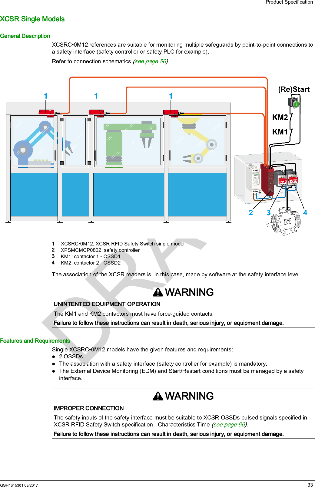
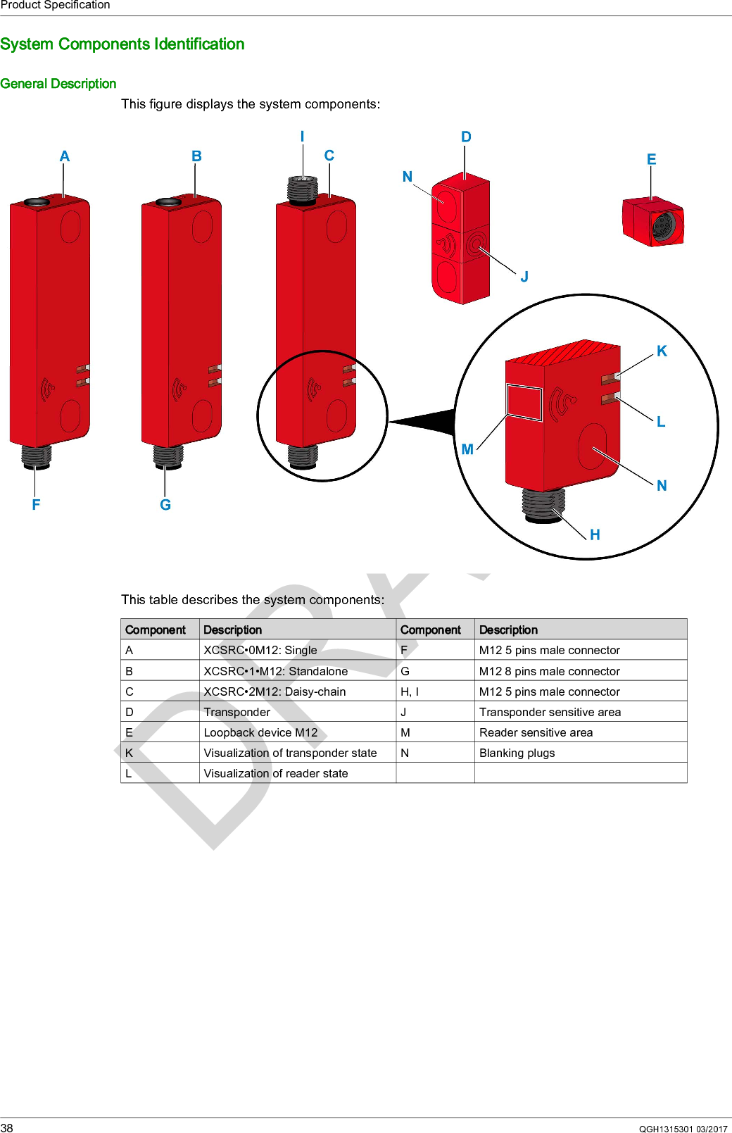
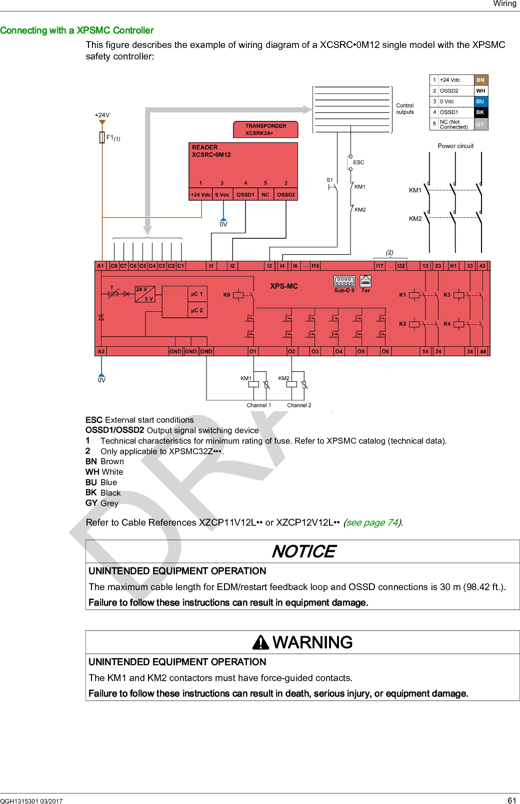
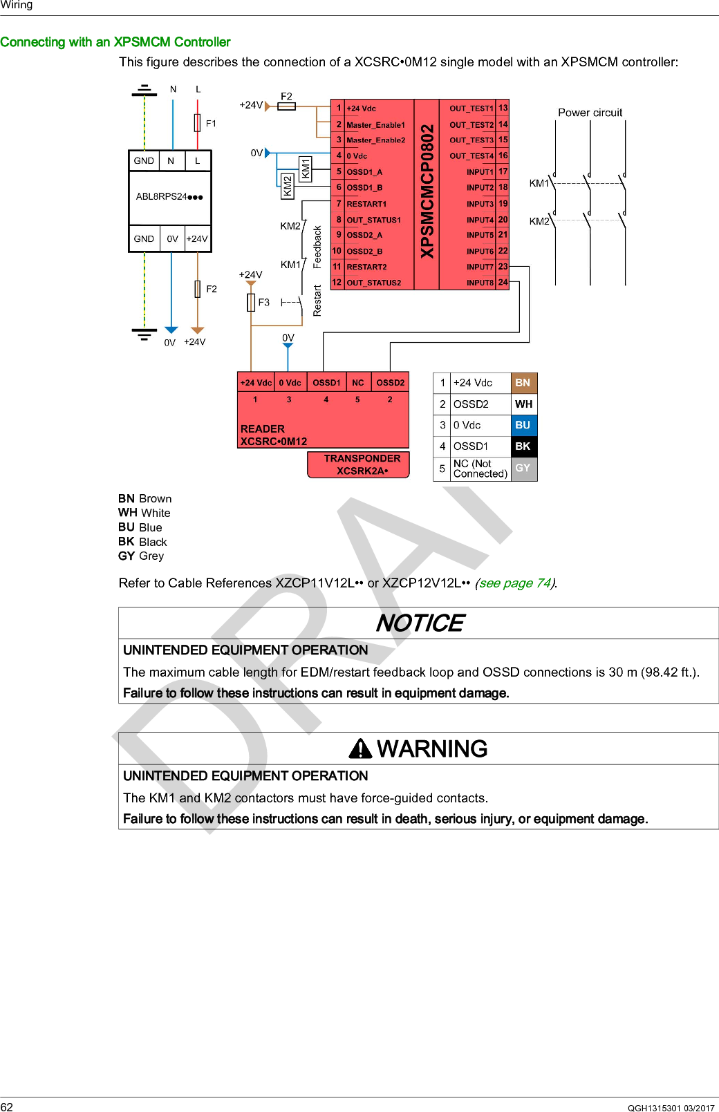
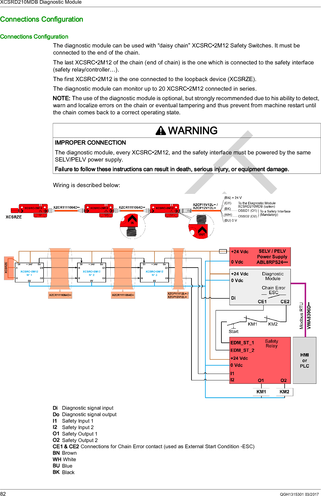
![Product SpecificationQGH1315301 03/2017 31A M12 plug (XCSRZE) must be connected to the reader which starts the chain (loopback device).Recommended diagnosis of the chain status with the XCSRD210MDB diagnostic module (see page 77).Daisy-chain models XCSRC•2M12 are compliant with the following safety standards:SIL3 (IEC 61508) SILCL3 (IEC 62061), and PLe- Cat.4 (EN ISO 13849-1)The overall safety integrity level of the system must consider the number of XCSRC•2M12 switches connected in series but also the reliability data of the signal processing unit and the output system.According to EN ISO 13849-1 and/or EN IEC 62061, the PFHD corresponding to a SIL3 integrity level of a safety function must be within the following limits:10-7 > PFHD >10-8PFHD = average probability of dangerous failure per hour for high demand or continuous mode of operationThe contribution to the total PFHD of the switches , the signal processing unit, and the output system depends on the reliability data of the devices used in the application.An example of PFHD contribution of an entire safety function is given below:Theoretical maximum number of switches connectable in seriesIn this example, the maximum PFHD allowed for the series connection is:[PFHDmax] switches= 1x10⁻⁷ - 5.6x10⁻⁹ - 24.7x10-9 = 69.7x10⁻⁹The PFHD of one XCSR RFID Safety Switch is 5x10⁻¹⁰, it means that the theoretical maximum number of XCSR RFID Safety Switch that could be connected in series, without impacting the overall safety level (SIL3-PLe) would be Nmax = 69.7x10⁻⁹/5x10-10 = 139Thus, the maximum number of chainable switches will be more limited by electrical constraintsPractical maximum number of switches connectable in seriesIn practice, by considering a realistic number of switches which could be connected in series as well as electrical limitations, the maximum number of XCSR RFID Safety Switch that can be connected in series has been limited to 20.WARNINGIMPROPER CONNECTIONThe safety inputs of the safety interface must be suitable to XCSR OSSDs pulsed signals specified in XCSR RFID Safety Switch specification - Characteristics Time (see page 66).Failure to follow these instructions can result in death, serious injury, or equipment damage.WARNINGIMPROPER CONNECTIONThe diagnostic module, every XCSRC•2M12, and the safety interface must be powered by the same power supply.Failure to follow these instructions can result in death, serious injury, or equipment damage.XCSR•• XPSAFL•• TeSys redundant contactor:PFHD = 5x10⁻¹⁰ per switch PFHD = 5.6x10⁻⁹ PFHD = 24.7x10⁻⁹Switches Logic Treatment Pre-actuators/Actuactors](https://usermanual.wiki/Schneider-Electric-France-L-Isle-d-Espagnac/XCSR/User-Guide-3387281-Page-31.png)


![XCSRD210MDB Diagnostic Module92 QGH1315301 03/2017CharacteristicsConformity/ApprovalsThis table provides the standards and approvals:Product Performances RequirementsElectrical characteristics:Interface:Electromagnetic compatibility:Mechanical characteristics:Conforming to standards EN/IEC 60947-1, EN/IEC 61326-2-1UL 508, CSA C22.2Approvals CE, cULus, EAC, RCMCharacteristics ValuePower supply The power supply must meet requirements of IEC 60204-1 relative to SELV/PELV power supply.Operating supply voltage +24 Vdc (+10%, -20%) = [+19.2 Vdc, +26.4 Vdc]Power consumption ≤ 300 mAPower on delay < 5 sReverse polarity protection Yes (excluding RJ45)Input signal Compatible with XCSRC•2M12 diagnostic signalProtection External fuseCharacteristics Detail ValueRelay Type MechanicalCurrent <200 mAVoltage ≤+24 VdcTon 1 ms / 3 msToff 1 ms / 3 msOutput power (RJ45) Voltage +5 Vdc (+/- 6%) = +4.7 Vdc,… +5.3 Vdc,Current <200 mA (protected)Modbus Baudrate Refer to Modbus settings accepted (see page 86).ParityRegistersPull out resistance Pull up: 562 Ω, pull down: 562 ΩCharacteristics Conform toEMC immunity withstands EN 61326-2-1Characteristics Detail ValueHousing material - PolycarbonateDisplay Type Two three-color LEDs (red, orange, green)Degree of protection - IP20Shock resistance - 15 gn / 11 ms Conforming EN/IEC 60068-2-27Vibration resistance - Conforming EN/IEC 60068-2-6+/- 3.5 mm (0.138 in) 5...8.4 Hz1 g (8.4…150 Hz)Impact - IK04Temperatures Operating 0…60 °C (32…140 °F)Storage -40…+85 °C (-40…185 °F)Humidity - <95% without condensation](https://usermanual.wiki/Schneider-Electric-France-L-Isle-d-Espagnac/XCSR/User-Guide-3387281-Page-92.png)