Schneider Electric France L Isle d Espagnac XGCS85 RFID Reader User Manual Manual Installation Instructions
Schneider Electric Industries France L'Isle d'Espagnac RFID Reader Manual Installation Instructions
Contents
- 1. Manual (Installation Instructions).pdf
- 2. Manual.pdf
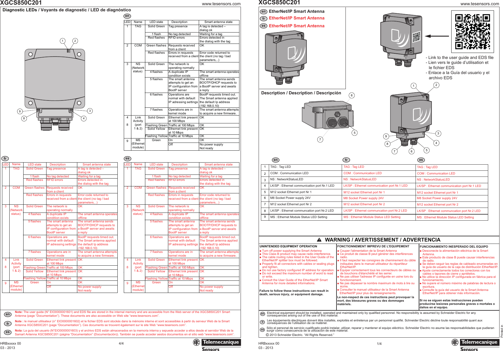
Manual (Installation Instructions).pdf

![Cette page sert à configurer l'adresse de la EtherNet/IP Smart Antenna :- Choisir le type d'allocation de l'adresse IP (adressage local ou automatique par DHCP)- Saisir l'adresse IP locale, le masque de sous-réseau et l'adresse de passerelle par défaut- Confirmer les nouveaux paramètres en cliquant sur le bouton [STORE CONFIGURATION] (Stocker la configuration)- Redémarrer la Smart Antenna pour appliquer les nouveaux paramètresEsta página se utiliza para configurar la dirección de la EtherNet/IP Smart Antenna:- Opción de asignación de dirección IP (direccionamiento local o automático con servicio DHCP).- Entrada de dirección IP local, máscara de subred y dirección predeterminada de pasarela.- Confirme los nuevos parámetros haciendo clic en el botón [STORE CONFIGURATION] (Almacenar configuración).- Apague y vuelva a encender la Smart Antenna para aplicar los nuevos parámetros.This page is used to configure the EtherNet/IP Smart Antenna address:- Choice of IP address allocation (local or automatic addressing with DHCP service)- Entry of the local IP address, subnet mask, and default gateway address- Confirm the new parameters by a click on [STORE CONFIGURATION] button- Cycle the power of the Smart Antenna to apply the new parametersmmin.www.tesensors.comXGCS850C2012/4Address configuration / Configuration de l'adresse / Configuración de la dirección- Home page / Page d'accueil / Página de inicio :- Setup page / Page de configuration / Página de configuración :enfresenfresenfresenfres03 - 2013HRBxxxxx 0003 - 2013HRBxxxxx 00www.tesensors.comXGCS850C2013/4PELV Power supply - The 0 V must be connected to the earth to increase EMC strength.Alimentation TBTS - Le 0 V doit être relié à la terre pour améliorer la CEM.Alimentación eléctrica PELV - Los 0 V se deben conectar a tierra para mejorar la CEM.Connectors wiring / Câblage des connecteurs / Cableado de conectores1324––––TD+TD-RD+RD-Not connectedNot connectedNot connectedNot connected41235 738 7 6 5 4 2 1612345 78M12 - 4 pinsConnectorM12Contact Signal RJ45Contact12364578RJ45Connectorc + 24 VNot connectedc 0 VNot connected1324 1 BN2 WH3 BU4 BK6652.56803.15AA: 3,6 Nm / 31.9 lbf.in301.181.57401.574027,51.08250.9811,50.45281.1933.66150.59652.56803.154 x Ø 5,54 x Ø 0.217Dimensions / Encombrements / DimensionesWiring Diagrams / Schémas de câblage / Esquemas de cableadoUtilization precautions / Précautions de mise en oeuvre / Precauciones de instalaciónXGSZp2E45ppXZCP0941LpXGSZ12E12ppASI67FACC1(*)EtherNet/IP2n1(Ethernet M12 D coded - 5 pins socket) (M8 - 4 pins male socket)e >20 mme >0.787in.mmin. mmin.M12 connectors: Maximum tighteningtorque = 1.5 N.m (13.3 lb-in)Connecteurs M12 : Couple de serrage maximal = 1,5 N.m (13.3 lb-in)Conectores M12: Par de apriete máximo = 1,5 N.m (13.3 lb-in)M8 connectors: Maximum tighteningtorque = 0.5 N.m (4.4 lb-in)Connecteurs M8 : Couple de serrage maximal = 0,5 N.m (4.4 lb-in)Conectores M8: Par de apriete máximo = 0,5 N.m (4.4 lb-in)e3 e4e1 ue2 ue3 ue1XGHB90E340XGHB221346XGHB320pppXGHB211345XGHB44ppp430/6.93 750/29.53 280/11.02280/11.02 530/20.87 260/10.24310/12.2 540/21.26 240/9.45200/7.87 370/14.57 170/6.69310/12.2 400/15.75 160/6.3d1ud2 u110/4.33 140/5.51120/4.72 50/1.97190/7.48 60/2.36120/4.72 20/0.7970/2.76 40/1.5760/2.36 10/0.3960/2.36 10/0.3960/2.36 10/0.39XGHB90E340XGHB221346XGHB320345XGHB211345XGHB444345XGHB445345XGHB440845XGHB443245IP address setup by the Web server:The XGCS850C201 Smart Antenna includes a Web server.The factory setting for the IP address of the XGCS850C201 is: 192.168.0.10Connection to the Web server Home pageConfigure the computer IP address with an address which is compatible withthe Smart Antenna (example: Smart Antenna = 192.168.0.10 V PC = 192.168.0.1)From your PC browser, enter the following address: http://192.168.0.10/Configuration de l'adresse IP par le serveur Web :La Smart Antenna XGCS850C201 comprend un serveur Web.Le réglage usine de l'adresse IP du XGCS850C201 est : 192.168.0.10Connexion à la page d'accueil du serveur WebConfigurer l'adresse IP de l'ordinateur avec une adresse compatible àcelle de la Smart Antenna(exemple : Smart Antenna = 192.168.0.10 V PC = 192.168.0.1)Configuración de dirección IP mediante el servidor web:La Smart Antenna XGCS850C201 incluye un servidor Web.El ajuste de fábrica de la dirección IP de la XGCS850C201 es: 192.168.0.10Conexión con la página de inicio del servidor WebConfigure la dirección IP del ordenador con una dirección que sea compatiblecon la Smart Antenna (ejemplo: Smart Antenna = 192.168.0.10 V PC = 192.168.0.1)En el explorador del PC, introduzca la siguiente dirección: http://192.168.0.10/OsiSense R XG RFiD - EtherNet/IP Smart Antenna - XGCS850C201Web site version : 2.0.2Copyright © 2000 - 2012, Schneider Electric. All Rights ReservedOsiSense R XG RFiD - EtherNet/IP Smart Antenna - XGCS850C201Web site version : 2.0.2Copyright © 2000 - 2012, Schneider Electric. All Rights ReservedIP address:Subnet mask:Default Gateway:Device Name:IP ParametersApply Undo1922551921682551680255 00101.........DHCP ClientAutomatic (BootP)Local (Stored IP)Ethernet Frame FormatEthernet ParametersEthernet IIConfigurationIP & FDR ClientSecurityHTTP User AdminEthernet PortsSNMP AgentConfigurationWeb site version : 2.0.2Copyright © 2000 - 2012, Schneider Electric. All Rights ReservedOsiSense R XG RFiD - EtherNet/IP Smart Antenna - XGCS850C201Security:User name and passwordare requested to secure the access to the web server.The factory settings are :User name= USERPassword= USERSecurity:User name and passwordare requested to secure the access to the web server.The factory settings are :User name= USERPassword= USERSecurity:User name and passwordare requested to secure the access to the web server.The factory settings are :User name= USERPassword= USERSelect [Configuration] in the menu of the home pageand then, [IP & FDR Client] in the left side of the pageModifications in this page are applied after a power cycling of the Smart AntennaSelect [Configuration] in the menu of the home pageand then, [IP & FDR Client] in the left side of the pageModifications in this page are applied after a power cycling of the Smart AntennaSelect [Configuration] in the menu of the home pageand then, [IP & FDR Client] in the left side of the pageModifications in this page are applied after a power cycling of the Smart Antennaeeede ed: depending on the connector sized: en fonction de la taille du connecteurd: dependiendo del tamaño del conectorMounting on a metal structureMontage sur une structure métalliqueMontaje sobre una estructura de metalDistance between two Smart Antennas according to the used tagDistance entre deux Smart Antenna en fonction de l’étiquette utiliséeDistancia entre dos Smart Antenna de acuerdo con la etiqueta utilizadaDistance between tagsDistance entre étiquettesDistancia entre las etiquetas(*): delivered with the Smart AntennaLivré avec la Smart AntennaSuministrado con la Smart Antennad1d2](https://usermanual.wiki/Schneider-Electric-France-L-Isle-d-Espagnac/XGCS85.Manual-Installation-Instructions-pdf/User-Guide-2064673-Page-2.png)