Schneider Electric France L Isle d Espagnac ZART ZART REMOTE use a Bluetooth module User Manual USERS MANUAL
Schneider Electric Industries France L'Isle d'Espagnac ZART REMOTE use a Bluetooth module USERS MANUAL
UserManual.wiki
>
Schneider Electric France L Isle d Espagnac
>
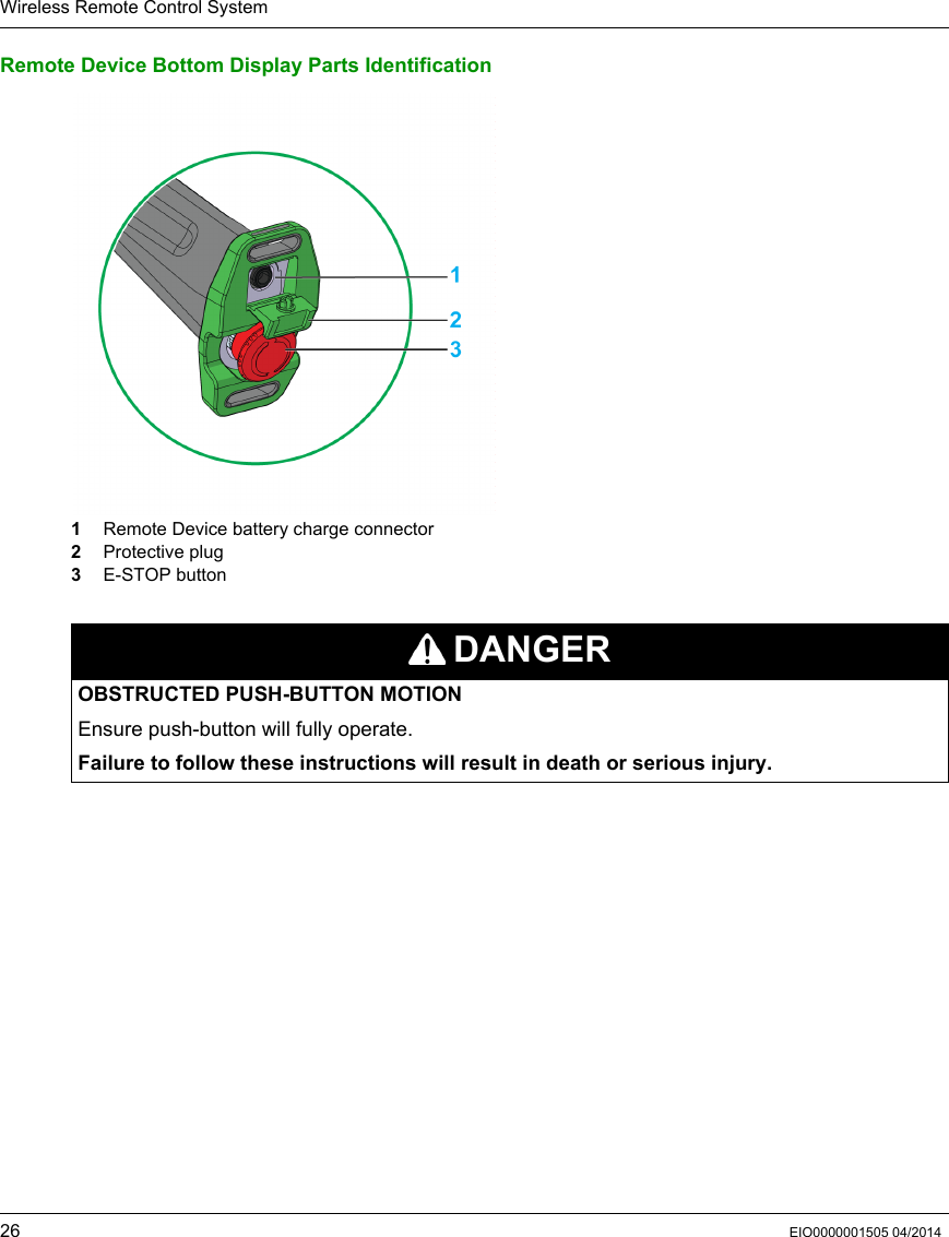
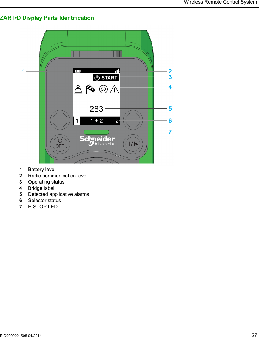
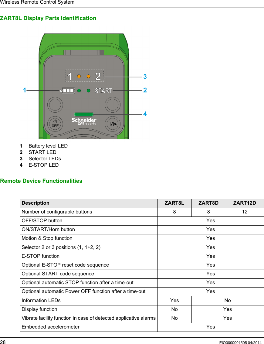
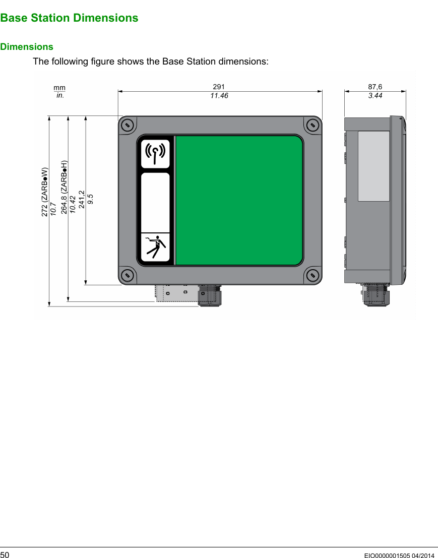
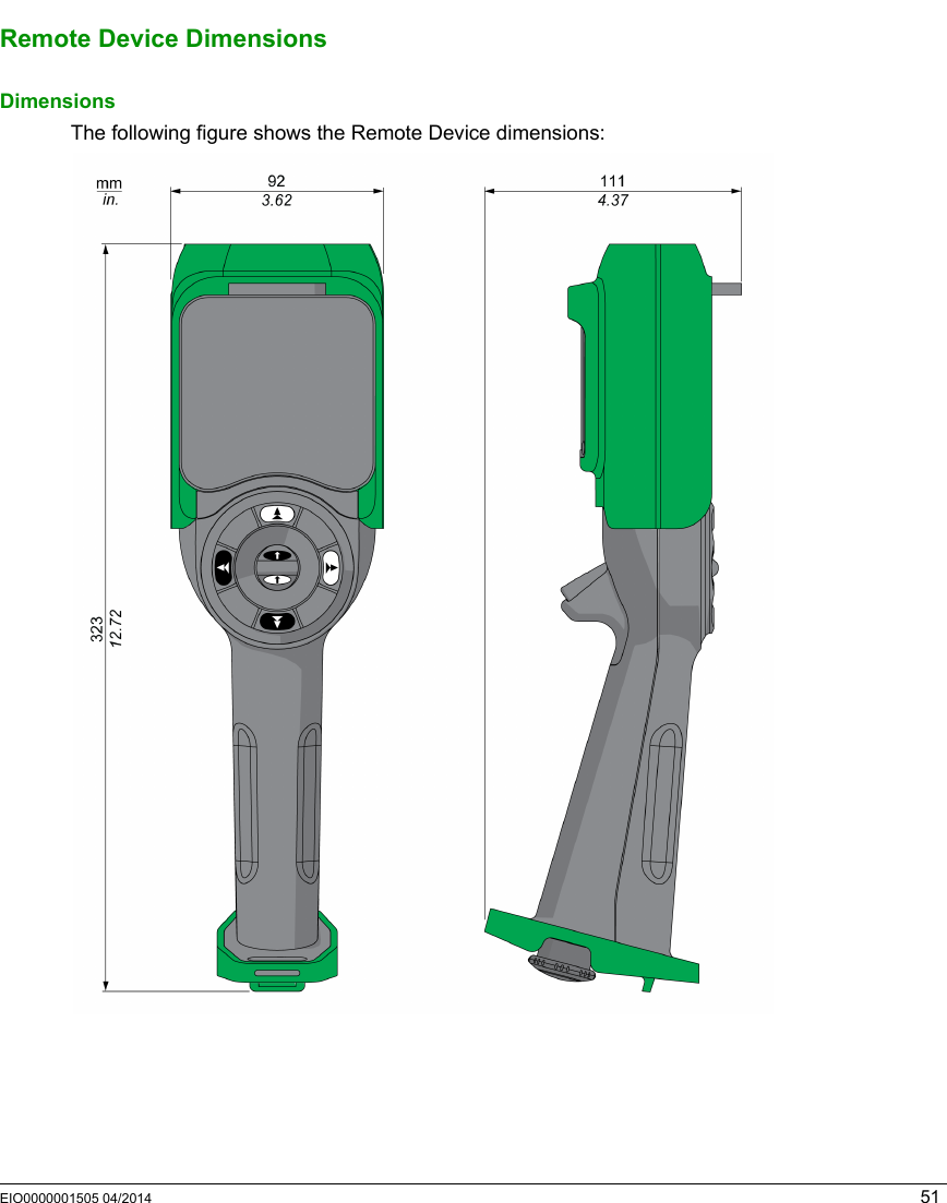
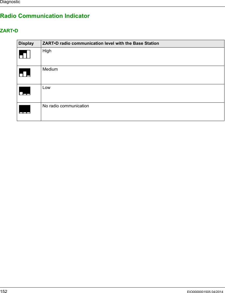
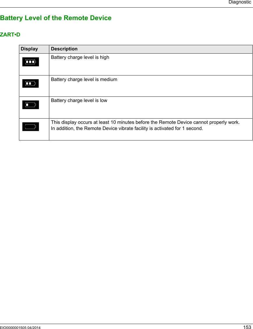
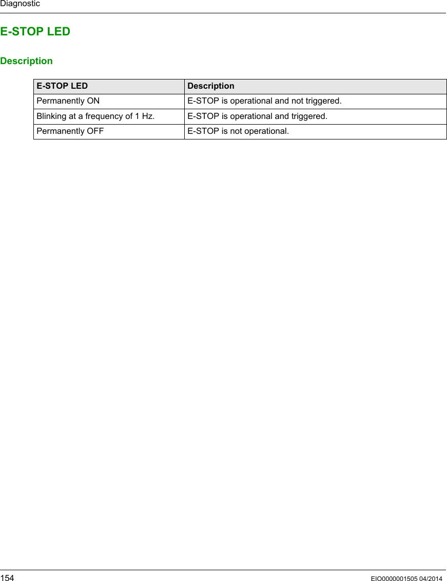
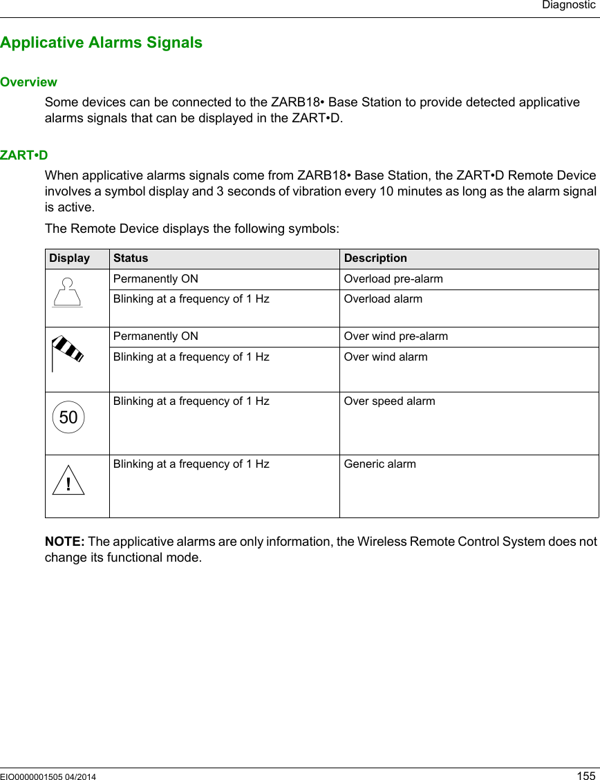
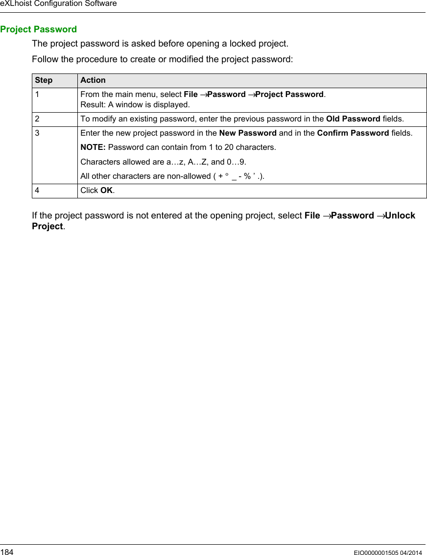
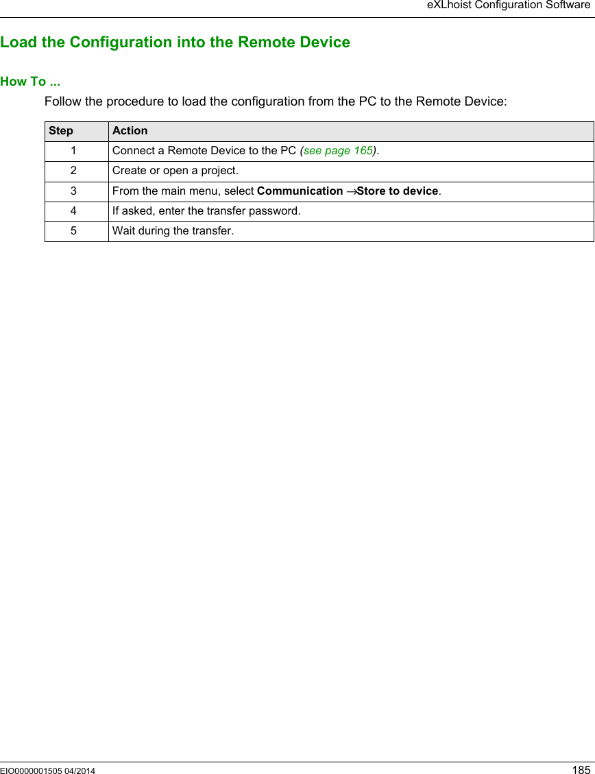
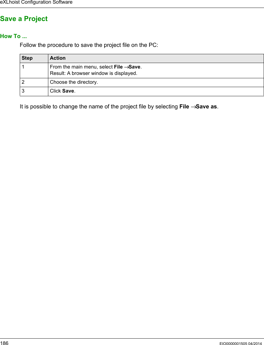
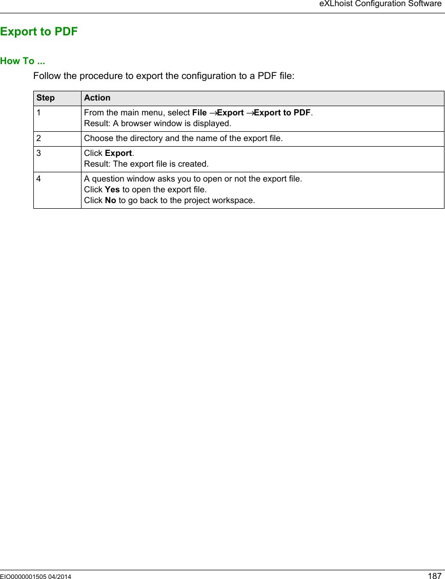
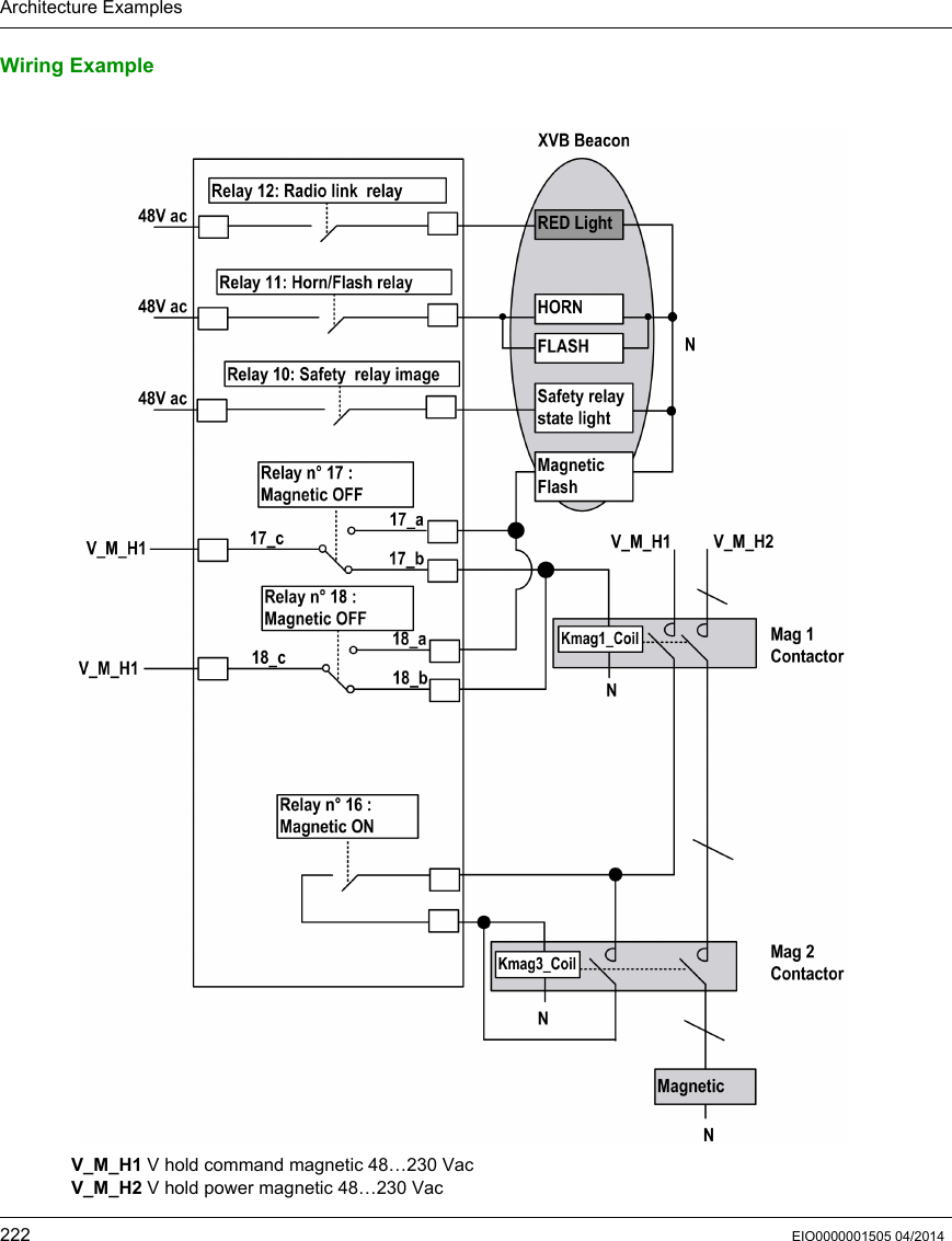
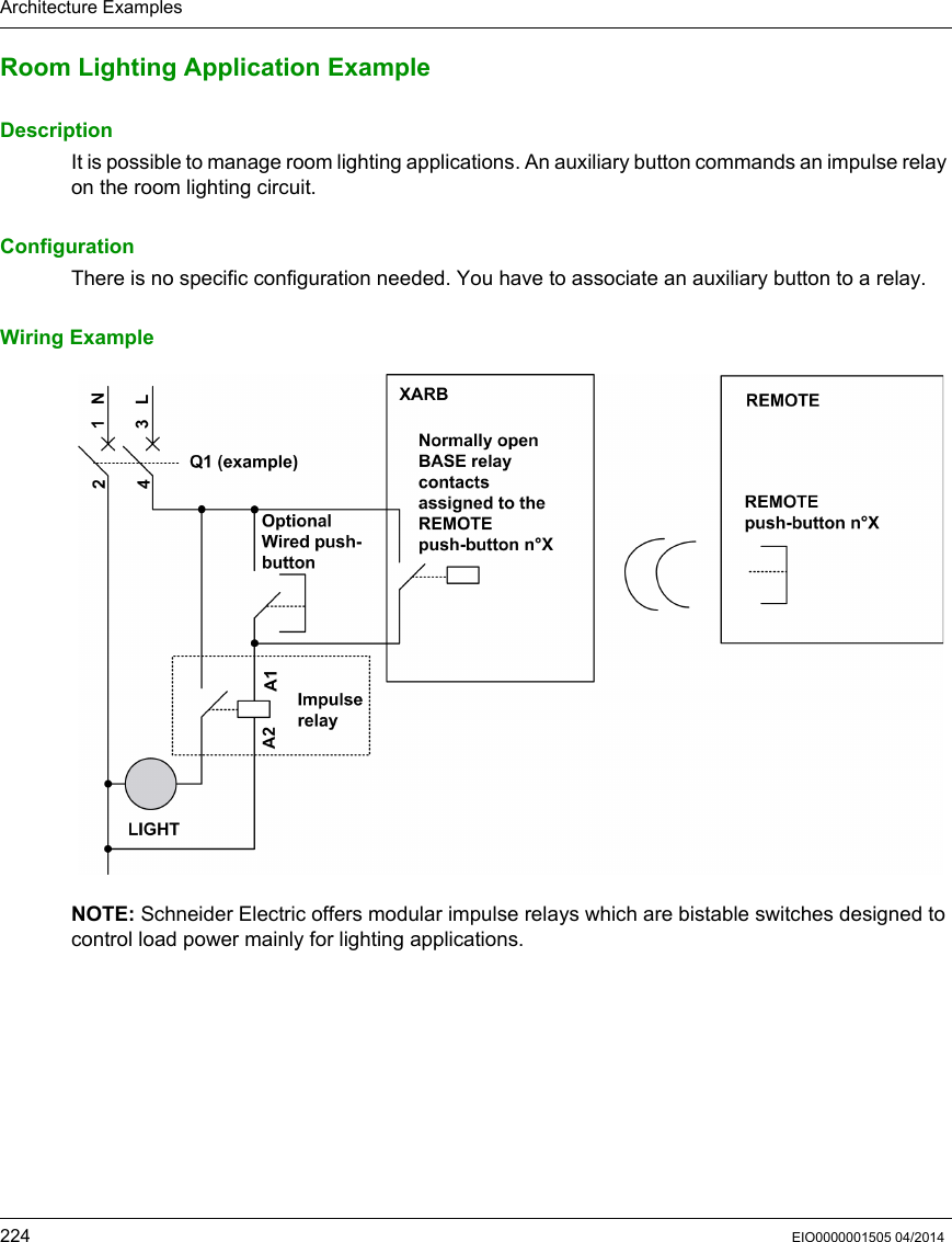
ZART User Manual
USERS MANUAL
Navigation menu
Upload a User Manual
Namespaces
Wiki Guide
HTML
PDF
Info
Views
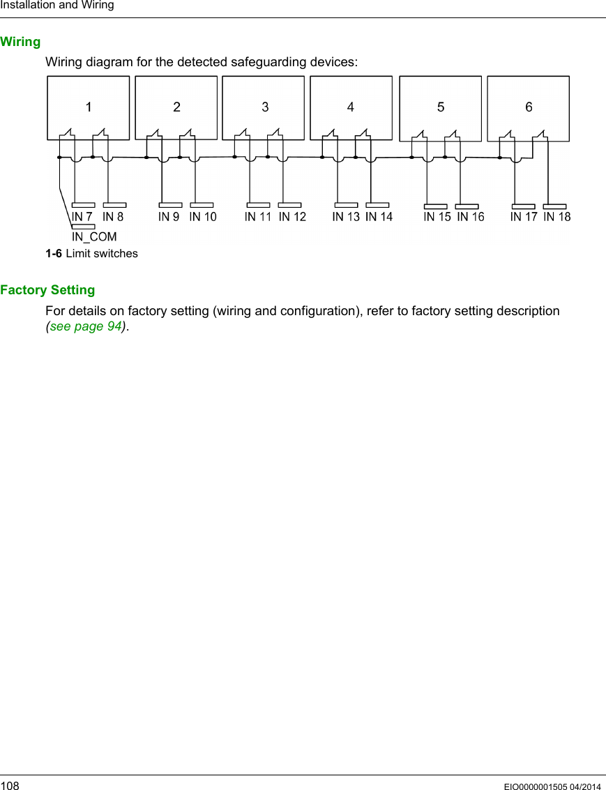
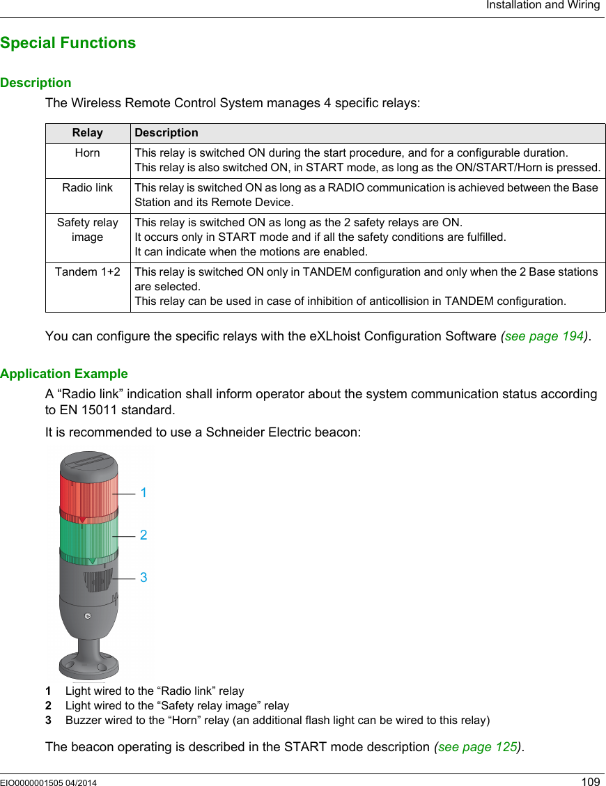
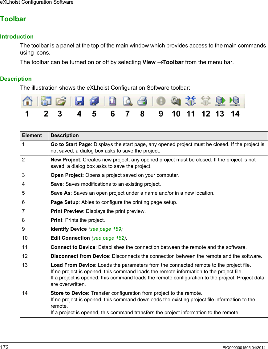
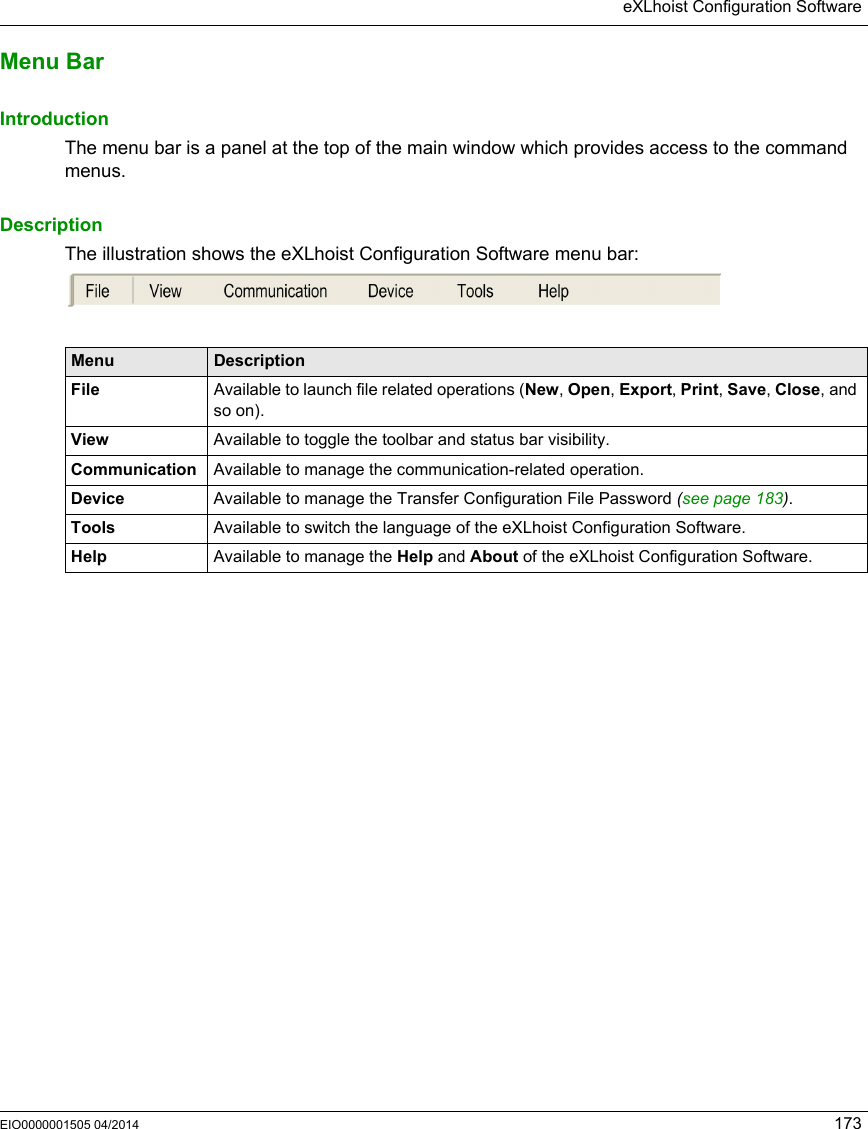
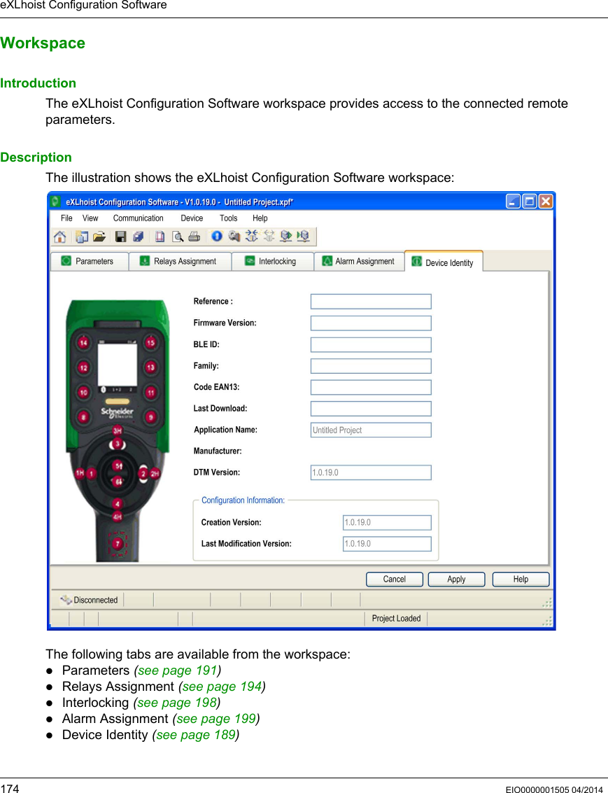
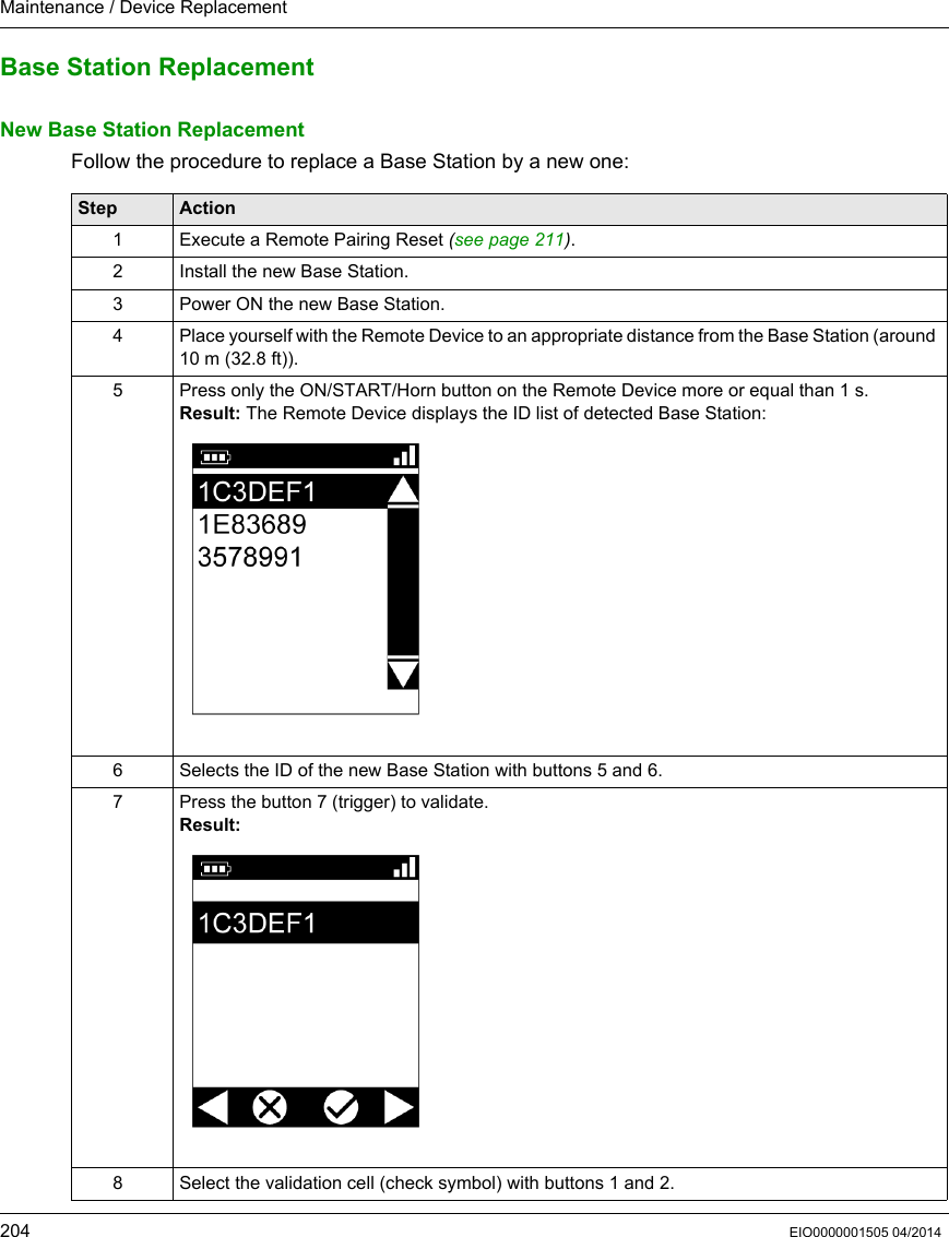
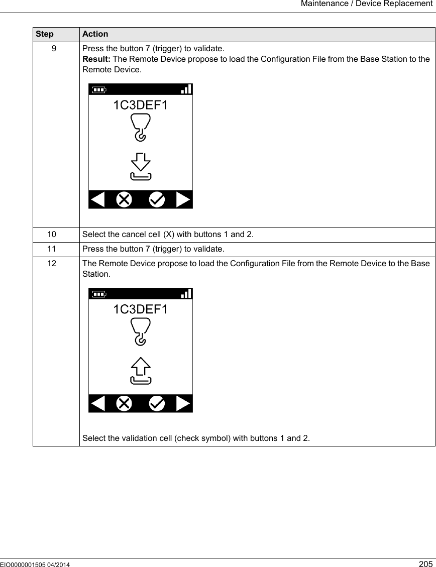
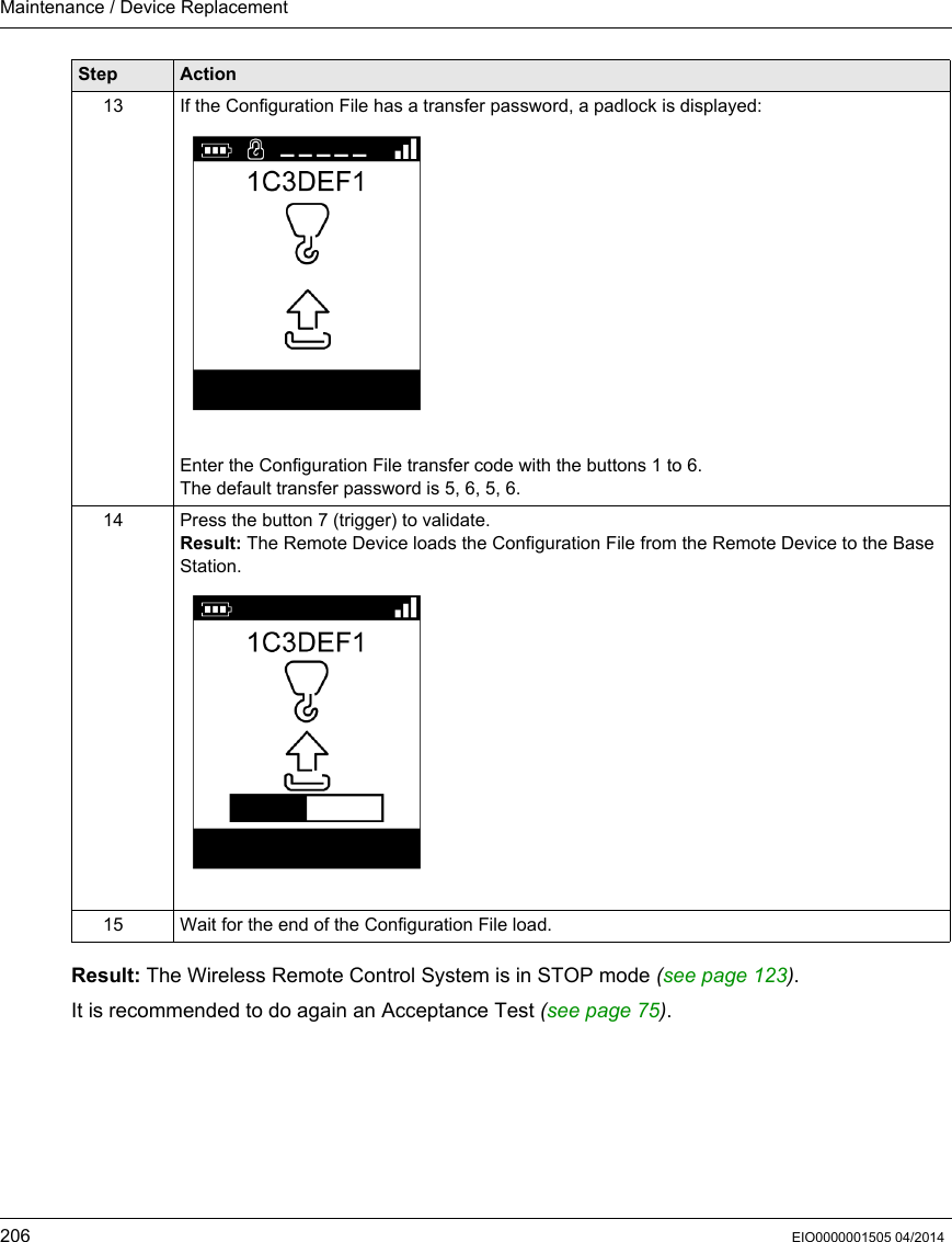
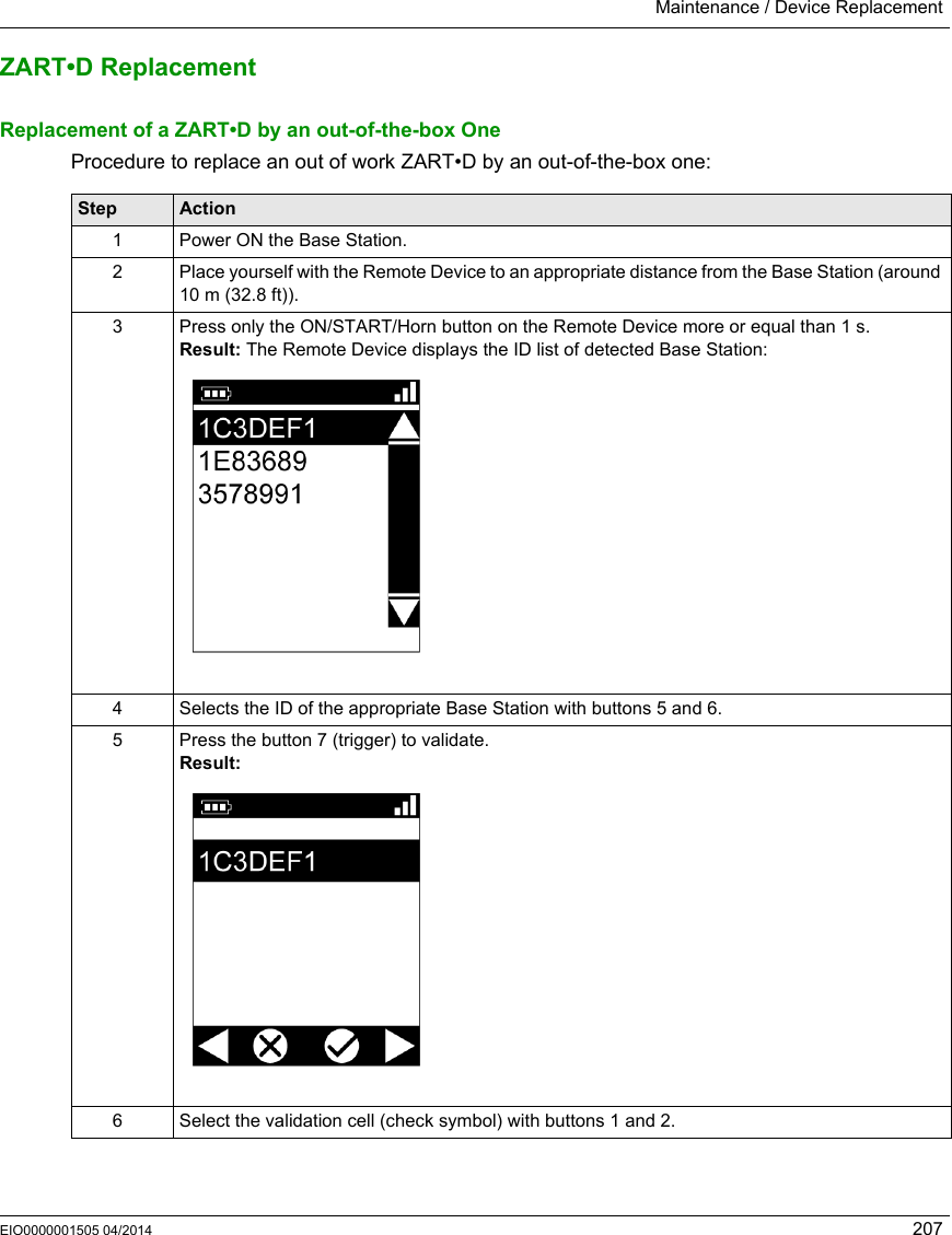
User Manual
Discussion / Help
Navigation