Schneider Electric Systems Canada OM900 900MHz FREQUENCY HOPPING SPREAD SPECTRUM RF MODULE User Manual O Series 07 07 indd
Trio Datacom Pty Ltd (a wholly owned company of Schneider Electric) 900MHz FREQUENCY HOPPING SPREAD SPECTRUM RF MODULE O Series 07 07 indd
USERS MANUAL

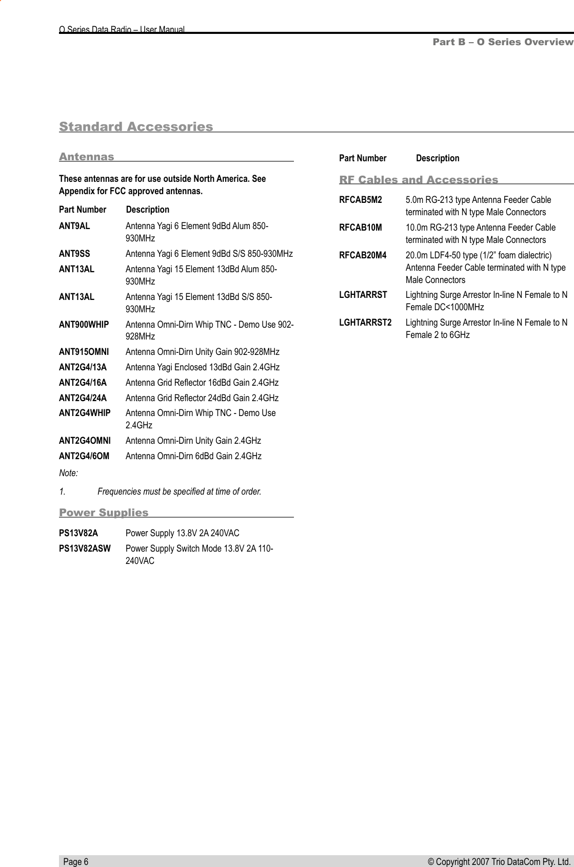
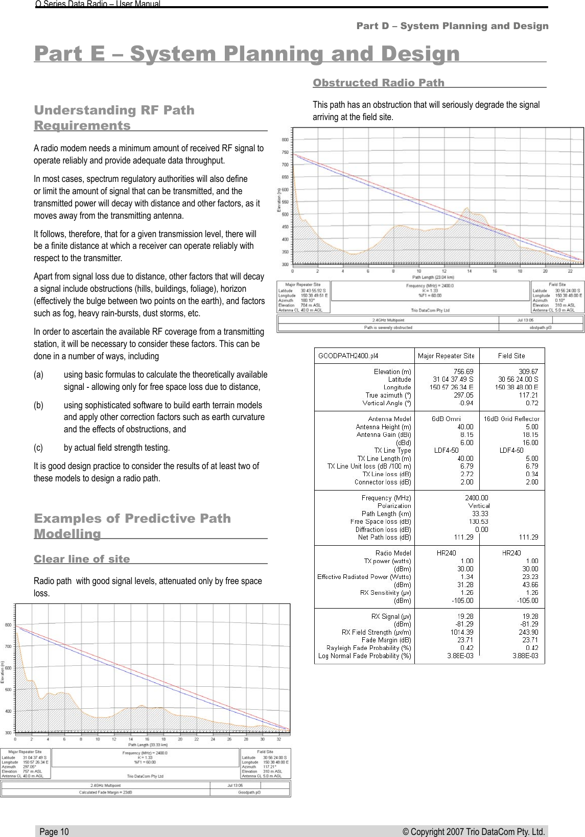
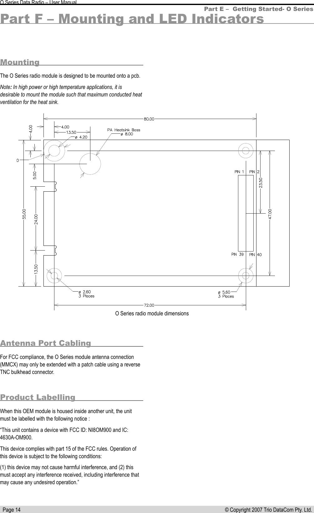
![Page 8 © Copyright 2007 Trio DataCom Pty. Ltd. O Series Data Radio – User ManualPin NameIn/OutComment Level1 PORT2-TxD I Input for transmit for Port 2 [Port A on K-Series] 3.3V TTL2 PORT2-RxD O Output for received data for Port 2 [Port A on K-Series] 3.3V TTL3 PORT2-CTS O Flow control of TxD for Port 2 [Port A on K-Series] 3.3V TTL4 PORT2-RTS I Flow control of TxD for Port 2 [Port A on K-Series] 3.3V TTL5 PORT2-DTR I Flow control of RxD for Port 2 [Port A on K-Series] 3.3V TTL6 VCC I 3.3V Supply Input 100mA +/-5%7 SysSerIn I Diagnostics/FDL input data or Testmode command 3.3V TTL8 SysSerOut O Diagnostics/FDL output or Testmode command 3.3V TTL9 PORT2-DCD O Flow control of RxD for Port A 3.3V TTL10 PAVCC I PA Supply Input (3.3V – 5V) 700mA @ 5V +/-5%11 GND N/A12 PAVCC I PA Supply Input (3.3V – 5V) 700mA @ 5V +/-5%13 Analogue RSSI O Synthesised average of RSSI (20dB/V absolute reference TBD)[can also be used as a general purpose analogue output]0-2.5v14 GND N/A15 Tx_LED O Tx activity (Active Low) 3.3V TTL16 Analogue Input I General purpose analogue input. 66k input resistance. 0-6v17 Sync_LED O Masters: 100ms pulse when user data received (Active Low)Remotes/Bridges: pulsed every 1500ms for 100ms when master acquired, additional 100ms pulse when user data received (Active Low)3.3V TTL18 TxD_PORT1_LED O Pulsed for 100ms for any TxD activity for Port 1 [Port B on K-Series] (Active Low) 3.3V TTL19 RxD_PORT1_LED O Pulsed for 100ms for any RxD activity for Port 1 [Port B on K-Series] (Active Low)3.3V TTL20 TxD_PORT2_LED O Pulsed for 100ms for any TxD activity for Port 2 [Port A on K-Series] (Active Low) 3.3V TTL21 RxD_PORT2_LED O Pulsed for 100ms for any RxD activity Port 2 [Port A on K-Series] (Active Low)3.3V TTL22 Pwr_LED O DC power OK (Active Low) 3.3V TTL23 nFACT/TEST-MODEI Reset factory defaults (Active Low on power-up) orTest Mode (Active High on power-up) orNeither (tri-state)If this pin is pulled high once the unit is in a fatal error state the fatall error condition will be indicated on the LED status lines.3.3V TTL24 PTT I Keys the radio at maximum TX/RX duty cycle using the current programmed channel selection and output power (Active Low).Note that while a radio is in this mode no data can be passed, the RSSI indication on other units will not respond to the radio being PTT keyed and it may block other systems.3.3V TTL25 TxInhibit I Tx inhibit for hot standby operation (Active High) 3.3V TTL26 nSHUTDOWN_IN I Power down entire module (Active Low) 3.3V TTL27 TxSync Input I Tx Sync input 3.3V TTLPart D – Module Pinouts](https://usermanual.wiki/Schneider-Electric-Systems-Canada/OM900/User-Guide-819556-Page-8.png)
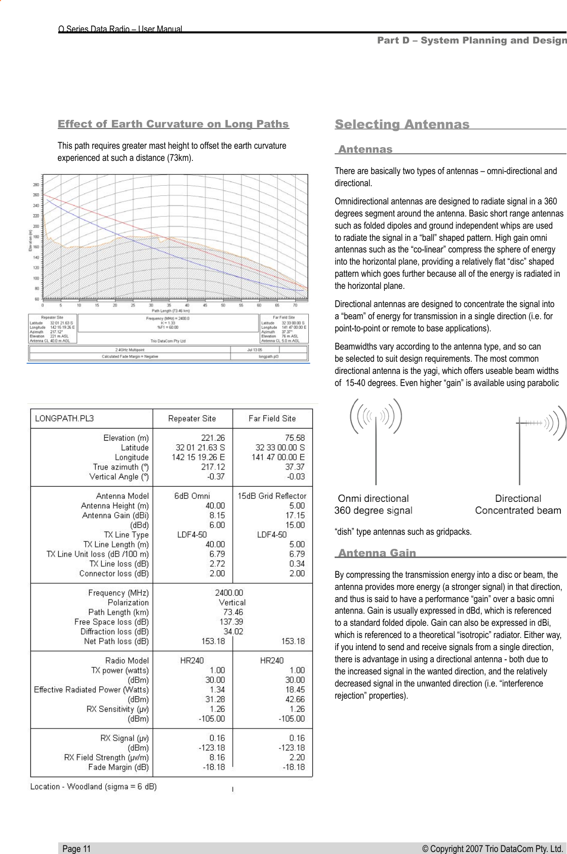
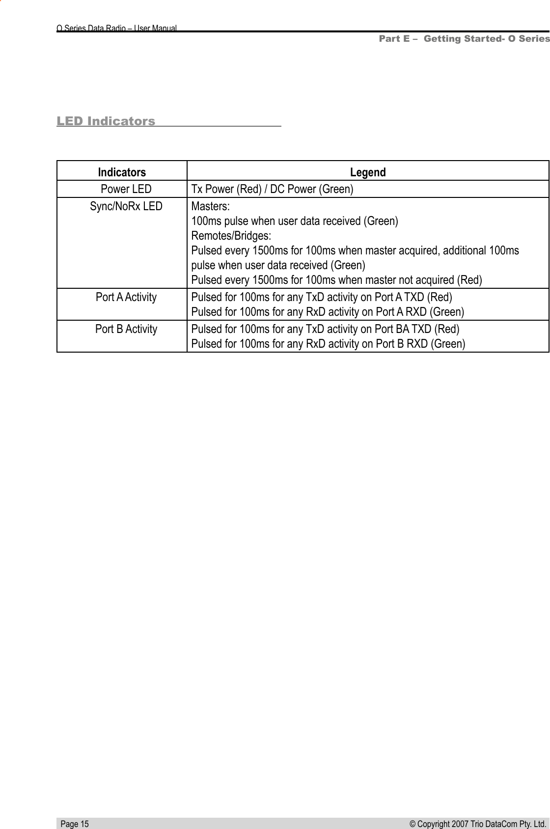
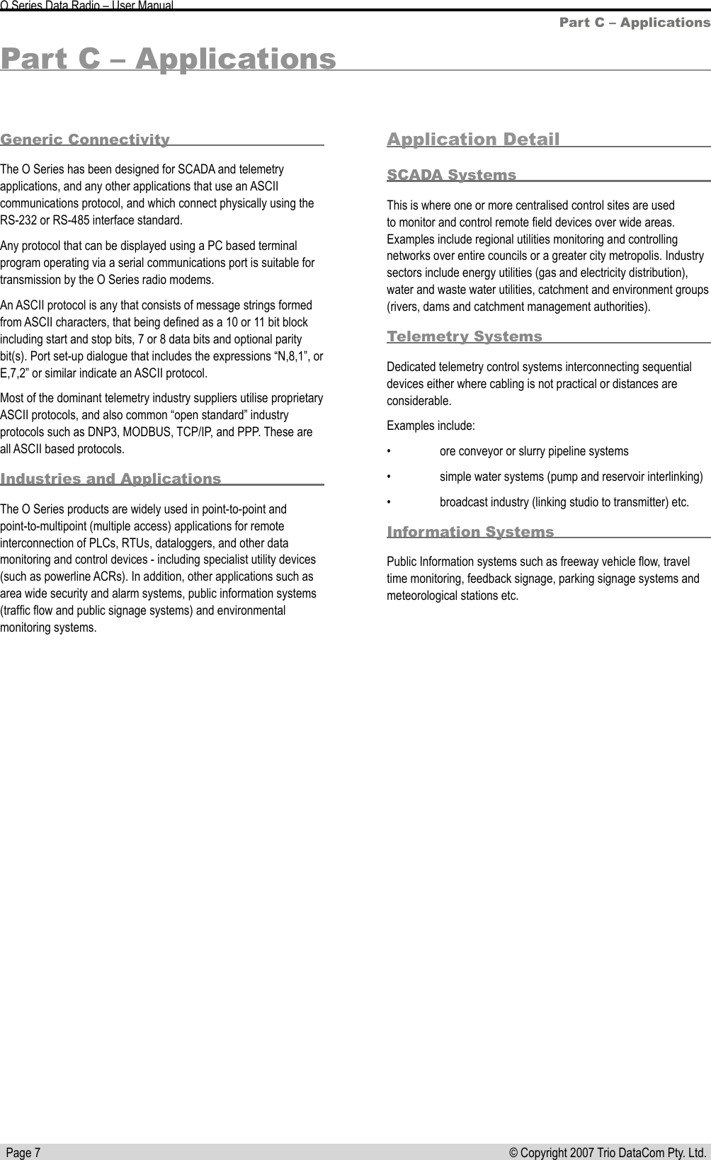
![Page 9 © Copyright 2007 Trio DataCom Pty. Ltd. O Series Data Radio – User ManualPin NameIn/OutComment Level28 TxSync Output O Tx Sync output 3.3V TTL29 PORT1-TxD I Input for transmit for Port 1 [Port B on K-Series] 3.3V TTL30 PORT1-RxD O Output for received data for Port 1 [Port B on K-Series] 3.3V TTL31 PORT1-RTS I Flow control of TxD for Port 1 [Port B on K-Series] 3.3V TTL32 PORT1-CTS O Flow control of TxD for Port 1 [Port B on K-Series] 3.3V TTL33 PORT1-DTR I Flow control of RxD for Primary Data Port [Port B on K-Series] 3.3V TTL34 PORT1-DCD O Flow control of RxD for Port 1 [Port B on K-Series] 3.3V TTL35 TWD IO I2C Data IO 3.3V TTL36 TWCK O I2C Clock 3.3V TTL37 SUPPLY_MONI-TORI Used to monitor the 10-30V input supply. Requires external 15k/1k resistive divider. (0-48V monitor range)0-3V, Hi-Z38 SHUTDOWN_OUTO Used to shutdown the main switcher once the uP is in the correct state 3.3V TTL39 NoSIG_LED O Masters: not activityRemotes/Bridges: pulsed every 1500ms for 100ms when master not ac-quired (Active Low)3.3V TTL40 NVRAM-WP O Connected to the write protect pin on the NVRAM on the K-Series (Active High)3.3V TTL](https://usermanual.wiki/Schneider-Electric-Systems-Canada/OM900/User-Guide-819556-Page-9.png)