Schneider Electric Systems Canada QB150QP150 VHF Remote Link Transceiver User Manual
Trio Datacom Pty Ltd (a wholly owned company of Schneider Electric) VHF Remote Link Transceiver
User Manual
1
Document Number: 0100SM1401 Issue: 12-16
Trio Q Data Radio
User Manual

2 Document Number: 0100SM1401 Issue: 12-16
Part G– Quick Start Guide 91
Step-by-Step Point to Point Setup 91
QH Hot Standby Quick Start Guide 95
Step-by-Step eDiags Setup 98
System Topology Configuration 99
Router Mode 104
Network Address Translation (NAT) 108
Virtual LAN (VLAN) 111
Serial and MODBUS 115
Single Frequency (Simplex) Mode 120
E-Series Emulation Mode 122
Part H – Advanced 124
Connectivity 124
Ease of Use 132
Security 155
Part I – Installation & Commissioning 158
Optimising the Antenna for Rx Signal 160
Commissioning 161
Part J – Firmware Updating and Maintenance 162
Firmware Updating 162
Global Firmware Updating 164
Fuse Replacement - QR 171
Part K – Open Source License Acknowledgements 172
Part L – Support Options 173
Contents
Part A – Preface 3
Safety Information 3
Revision History 6
Important Information 6
Compliance Information 7
Part B – Feature Overview 8
Introduction 8
Features and Benefits 9
Q Data Radio Range 10
Part C – System Topologies & Operating Modes 12
System Topologies 12
Operating Modes 17
Part D – Feature Detail 19
Hardware 19
Efficiency and Bandwidth 21
Connectivity 32
Ease of Use 35
Security 42
Part E – Radio Planning and Design 44
Radio Path analysis 44
BER & Fade Margin 46
Radio Accessories 47
Part F – Quick Reference Guide 50
Introduction 50
Half Duplex Radio - QR150 50
Half Duplex Radio - QR450 57
Full Duplex Radio - QB 64
Hot Standby Half Duplex Radio - QP 69
Hot Standby Full Duplex Radio - QH 74
LED indicators 81
Connecting Antennas 84
Communication Ports 84
Activating Transmitter 86
Factory Default 86
Digital I/O 87
Connecting to Web User Interface (WUI) 89
Resolving Ethernet Connection Issues 90
3
Document Number: 0100SM1401 Issue: 12-16
Safety Information
Read these instructions carefully, and look at the
equipment to become familiar with the device before
trying to install, operate, or maintain it. The following
special messages may appear throughout this
documentation or on the equipment to warn of potential
hazards or to call attention to information that clarifies or
simplifies a procedure.
WEEE Regulation (Europe)
This symbol on the product or its
packaging indicates that this product
must not be disposed of with other waste.
Instead, it is your responsibility to dispose
of your waste equipment by handing it over to a designated
collection point for the recycling of waste electrical and
electronic equipment. The separate collection and recycling
of your waste equipment at the time of disposal will help
conserve natural resources and help ensure that it is
recycled in a manner that protects human health and the
environment. For more information about where you can
drop off your waste equipment for recycling, contact the
dealer from whom you originally purchased the product.
Dieses Symbol auf dem Produkt oder seinem Verpacken
zeigt an, daß dieses Produkt nicht mit anderer
Vergeudung entledigt werden darf. Stattdessen ist es Ihre
Verantwortlichkeit, sich Ihre überschüssige Ausrüstung zu
entledigen, indem es rüber sie zu einem gekennzeichneten
Ansammlungspunkt für die Abfallverwertung elektrische und
elektronische Ausrüstung übergibt. Die unterschiedliche
Ansammlung und die Wiederverwertung Ihrer
überschüssigen Ausrüstung zu der Zeit der Beseitigung
helfen, Naturresourcen zu konservieren und sicherzugehen,
daß es in gewissem Sinne aufbereitet wird, daß menschliche
Gesundheit und das Klima schützt. Zu mehr Information
ungefähr, wo Sie weg von Ihrer überschüssigen Ausrüstung
für die Wiederverwertung fallen können, treten Sie bitte mit
dem Händler in Verbindung, von dem Sie ursprünglich das
Produkt kauften.
This is the safety alert symbol. It is used to
alert you to a potential personal injury hazards.
Obey all safety messages that follow this
symbol to avoid possible injury or death.
The addition of this symbol to a Danger or
Warning safety label indicates that an electrical
hazard exists, which will result in personal injury
if the instructions are not followed.
Part A – Preface
Part A - Preface
Electrical equipment should be installed, operated,
serviced, and maintained only by qualified personnel. No
responsibility is assumed by Schneider Electric for any
consequences arising out of the use of this material.
WARNING
WARNING indicates a hazardous situation which, if not avoided, could result in
death or serious injury.
CAUTION
CAUTION indicates a hazardous situation which, if not avoided, could result in
minor or moderate injury.
NOTICE
NOTICE is used to address practices not related to physical injury.
WARNING
HAZARD OF BURN
The QR, QB and QP must be installed in a restricted access location.
Failure to follow these instructions can result in death or serious injury.
WARNING
LOSS OF CONTROL
• The designer of any control scheme must consider the potential failure modes
of control paths and, for certain critical control functions, provide a means to
achieve a safe state during and after a path failure. Examples of critical control
functions are emergency stop and over travel stop.
• Separate or redundant control paths must be provided for critical control functions.
• System control paths may include communication links. Consideration must be
given to the implications of anticipated transmission delays or failures of the link1
• Each implementation of equipment utilizing communication links must be
individually and thoroughly tested for proper operation before being placed
into service.
Failure to follow these instructions can result in death, serious injury, or
equipment damage.
WARNING
HAZARD OF RADIO FREQUENCY (RF) BURNS
Ensure that a matching load or antenna is attached to the RF port prior to
applying power to the device.
Failure to follow these instructions can result in death or serious injury.
WARNING
HAZARD OF EXPLOSION
Ensure that all connected equipment is grounded to the power source ground
termination.
Failure to follow these instructions can result in death or serious injury.
For the definition of a restricted access location, refer to the
ETSI EN 60950 standard.
WARNING
HAZARD OF THERMAL BURNS
High operating temperature.
• Avoid direct contact with device while in operation.
• Install device in a restricted access location to avoid unintentional contact.
Failure to follow these instructions can result in death or serious injury.
1 For additional information about transmission delays or
failures of the link, refer to NEMA ICS 1.1 (latest edition).
Safety Guidelines for the Application, Installation, and
Maintenance of Solid State Control or its equivalent in
your specific country, language, and/or location.
4 Document Number: 0100SM1401 Issue: 12-16
Before using this product, read the Safety Information, Compliance information and all recommendations related to the
purchased wireless communications equipment found within the Installation and Commissioning section found within the
product user manual. The product user manual is available at www.schneider-electric.com
This environment is “enclosed”. It can be installed without any specific protection in areas with restricted access and low pollution
levels (not exceeding 2), for example; stations or control rooms which have neither machines nor any activity generating metallic
dust or other metallic particles. In other environments, it is recommended to follow rules as defined in the user manual. For the
definition of a restricted access location, refer to the ETSI EN 60950 standard.
Environment
Part A - Preface
WARNING
HAZARD OF DEATH OR SERIOUS INJURY
• The QR, QB and QP must be installed in a restricted access location.
• Ensure that the operating temperature (air surrounding equipment) never exceeds 70 °C (158 °F)
• Ensure that all radio equipment is installed with a lightning arrestor.
• Ensure that all connected equipment is grounded to the power source ground termination.
• Where an internal fuse is to be replaced, the replacement fuse must be of the specied
type and current rating. Refer to fuse replacement instructions within the Product User
Manual before servicing.
• Ensure that a matching load or antenna is attached to the RF port prior to applying power
to the device.
Failure to follow these instructions can result in death or serious injury.
WARNING
LOSS OF CONTROL
• The designer of any control scheme must consider the potential failure modes of control paths and,
for certain critical control functions, provide a means to achieve a safe state during and after a path
failure. Examples of critical control functions are emergency stop and over travel stop.
• Separate or redundant control paths must be provided for critical control functions.
• System control paths may include communication links. Consideration must be given to the
implications of anticipated transmission delays or failures of the link1
• Each implementation of equipment utilizing communication links must be individually and
thoroughly tested for proper operation before being placed into service.
Failure to follow these instructions can result in death, serious injury, or equipment damage.
1 For additional information about transmission delays or failures of the link, refer to NEMA ICS 1.1 (latest edition). Safety Guidelines for
the Application, Installation, and Maintenance of Solid State Control or its equivalent in your specific country, language, and/or location.
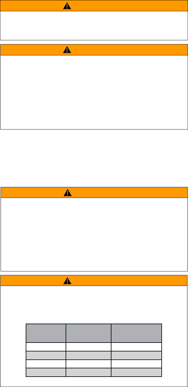
WARNING
HAZARD OF DEATH OR SERIOUS INJURY
• RF Exposure - The radio equipment described in the Product User Manual emits low level radio
frequency energy. The concentrated energy may pose a health hazard depending on the type of antenna
used. To satisfy EU, FCC and Industry Canada requirements a minimum separation distance should be
maintained between the antenna of this device and persons during operation as per the table below
Range of
Antenna system
gains (dBd)
Minimum
Separation from
Antenna (Meters)
Minimum Separation
from Antenna
(Feet Decimal)
0 to 4 1.6 5.3
4 to 8 2.6 8.6
8 to 12 4.1 13.5
12 to 16 6.4 21
Failure to follow these instructions can result in death or serious injury.
WARNING
HAZARD OF UNINTENDED EQUIPMENT OPERATION
To help prevent equipment malfunction, take every precaution during installation against incorrectly
activating the wireless communications equipment. This equipment is not a functional safety product.
Failure to follow these instructions can result in death or serious injury, and equipment damage.

5
Document Number: 0100SM1401 Issue: 12-16
In order to improve the security of the installation, follow the rules below:
Wiring
NOTICE
HAZARD OF EQUIPMENT DAMAGE
• The radio modem can be damaged if there is any potential difference between the
chassis-ground, RS-232 signal ground, power (-) input, or antenna coaxial shield. Before
connecting any wiring, ensure that all components are earthed to a common ground point.
• The QR150, with the Rx antenna port enabled, can be damaged if the isolation between
the Tx and Rx antenna is less than 20 dB. Before connecting the QR150 to an antenna
system, ensure that the isolation between the Tx and Rx antennas is greater than 20 dB.
• The QB, when operating with the same transmit and receive frequencies, can be
damaged if the isolation between the Tx and Rx antenna is less than 47 dB. Before
connecting the QB to an antenna system, ensure that the isolation between the Tx and Rx
is greater than 47 dB.
• The QP150 type D (part number TBURQP1xx-xxxxxxxD), can be damaged if the isolation
between the Tx and Rx antenna is less than 20 dB. Before connecting the QP150 to an
antenna system, ensure that the isolation between the Tx and Rx is greater than 20 dB.
Failure to follow these instructions can result in equipment damage.
Part A - Preface

6 Document Number: 0100SM1401 Issue: 12-16
Revision History
Issue: 03-15 - (March 2015) Alarms and Events
Issue: 05-15 - (May 2015) Updated Compliance
Information.
Issue: 11-15 - (November 2015) Updates to support new
features in firmware
release 1.4.0
Issue: 06-16 - (June 2016) Updates to support new
features in firmware
release 1.5.0
Issue: 12-16 - (December 2016) Support for VHF Q
variant
Part A - Preface
Important Information
© Copyright 2016 Trio Datacom Pty Ltd All Rights
Reserved
This manual covers the operation of the Q Data Radio
range. Specifications described are typical only and are
subject to normal manufacturing and service tolerances.
Trio Datacom Pty Ltd reserves the right to modify the
equipment, its specification or this manual without prior
notification, in the interest of improving performance,
reliability or servicing. At the time of publication all data is
correct for the operation of the equipment at the voltage
and/or temperature referred to. Performance data
indicates typical values related to the particular product.
This manual is copyright by Trio Datacom Pty Ltd. All
rights reserved. No part of the documentation or the
information supplied may be divulged to any third party
without the express written permission of Trio Datacom
Pty Ltd.
The manual is also proprietary to Trio Datacom Pty Ltd
and are supplied for the purposes referred to in the
accompanying documentation and must not be used
for any other purpose. All such information remains
the property of Trio Datacom Pty Ltd and may not be
reproduced, copied, stored on or transferred to any
other media or used or distributed in any way save for
the express purposes for which it is supplied.
Products offered may contain software which is
proprietary to Trio Datacom Pty Ltd. However, the
offer of supply of these products and services does
not include or infer any transfer of ownership of such
proprietary information and as such reproduction or
reuse without the express permission in writing from Trio
Datacom Pty Ltd is forbidden. Permission may be applied
for by contacting Trio Datacom Pty Ltd in writing.
7
Document Number: 0100SM1401 Issue: 12-16
WARNING
HAZARD TO HEALTH DUE TO RADIO FREQUENCY (RF) EXPOSURE
• The radio equipment described in this user manual emits low level
radio frequency energy. The concentrated energy may pose a health
hazard depending on the type of antenna used.
• To satisfy EU, FCC and Industry Canada requirements a minimum
separation distance should be maintained between the antenna of
this device and persons during operation as per the table below.
Range of Antenna
system gains (dBd)
Minimum Separation
from Antenna (Meters)
Minimum Separation from
Antenna (Feet Decimal)
0 to 4 1.6 5.3
4 to 8 2.6 8.6
8 to 12 4.1 13.5
12 to 16 6.4 21
Failure to follow these instructions can result in death or serious injury.
Part A - Preface
Site Grounding
Ensure that the chassis mounting plate, power supply
(-) Ground, RTU terminal device, and lightning arrester,
are all securely connected to the ground in the building
installation or a common ground point to which an earth/
ground stake is attached.
R&TTE Directive (Europe)
Applies to models TBURQx4xx-Exxxxxxx
In order to comply with the R&TTE (Radio &
Telecommunications Terminal Equipment) directive
1999/5/EC, all radio modem installations must include
an external in-line lightning arrestor or equivalent device
that complies with the following specifications:
• DC Blocking Capability - 1.5kV impulse (Rise Time
10mS, Fall Time 700mS) (Repetition 10 Times)
or 1.0kV rms 50Hz sine wave for 1 minute.
Trio Datacom declares that the Q data radio range
is in compliance with the essential requirements and
other relevant provisions of the Directive 1999/5/
EC. Therefore the Trio Datacom Q data radio range is
labelled with the following CE-marking.
FCC Compliance (Hot Standby Controller Only)
This equipment has been tested and found to comply
with the limits for a Class B digital device, pursuant to
Part 15 of the FCC Rules. These limits are designed
to provide reasonable protection against harmful
interference in a residential installation. This equipment
generates, uses, and can radiate radio frequency energy
and, if not installed and used in accordance with the
instruction, equipment may cause harmful interference
to radio communications. However, there is no
guarantee that interference will not occur in a particular
installation. If this equipment does cause harmful
interference to radio or television reception, which can
be determined by turning the equipment off and on, the
user is encouraged to try to correct the interference by
one or more of the following measures:
• Re-orient to relocate the receiving antenna.
• Increase the separation between the equipment
and receiver.
• Connect the equipment into an outlet on a circuit
different to that which the receiver is connected.
• Consult the dealer or an experienced radio/
television technician for assistance.
Compliance Information
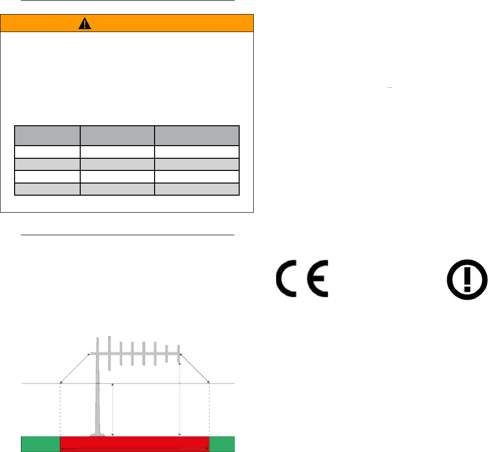
Exclusion Zone
3m Clearance
allowed for
5m
3.3m3.3m
Typical Antenna Installation Exclusion Zone
The diagram below shows the exclusion zone for a
typical antenna installation. The details of this typical
system are as follows:
• Q Data Radio - 40dBm (10W)
• Antenna - Yagi 14 dBd/16.15 dBi gain
• Lightning Arrestor - 0.5dB loss
• Cable Run - 1.5dB loss
0891
Collocating the QR450 remote (Europe)
The QR450 is a remote radio and should not be
collocated with other transmitting equipment.
FCC Compliance
This device complies with part 15 of the FCC rules.
Operation is subject to the following two conditions: (1) this
device may not cause harmful interference, and (2) this
device must accept any interference received, including
interference that may cause undesired operation.
The manufacturer is not responsible for any radio or TV
interference caused by unauthorised modifications to
this equipment. Such modifications could void the user’s
authority to operate the equipment.
When antennas are co-located on a community (shared)
site the correct site engineering must be performed to
ensure that RF exposure limits are met.
FCC requirements can be found in 47 CFR 1.1307(b)(3)

8 Document Number: 0100SM1401 Issue: 12-16
Part B – Feature Overview
Introduction
The Trio Q is a family of data radios designed for wireless transport of Telemetry and Remote SCADA data using the licensed
VHF and UHF spectrum.
Trio Q Data Radios are ideal where:
• Total ownership and control of the data radio network is required
• There are long distances to cover
• Public Communications (i.e.: Cellular) is too expensive or unreliable
• Variety of communications delivery is required
Trio Q Data radios are suitable for a wide variety of applications that require the transport of serial or Ethernet protocols,
including DNP, MODBUS and IEC, over distances of that up to 50Km (30 miles). Common applications include the monitoring
and control of remote assets in the management of:
• Water and Waste Water
• Electrical Distribution and Sub Station automation such as those found in Smart Grids
• The extraction and transportation of Oil & Gas
However, as data transport is transparent to the application, there are virtually no application-specific constraints, other than
data throughput and range.
A typical radio system topology permits a central master / control application, like a SCADA Host system for example, to
communicate with remotely-situated application equipment such as RTUs or PLCs; using single or dual-frequency radio
channels in the 150 MHz VHF band (Qx150) or 450 MHz UHF band (Qx450). A diverse range of system topologies
are possible, but in general remote sites communicate directly with the entry point or via repeater stations when direct
communication is not possible.
Trio Q Data Radios come in a variety of hardware form factors. The QR450 and QR150 Half-Duplex Radios, are ideal for
deployment at remote sites, and operates in simplex or half-duplex modes. Built around a rugged but compact die-cast housing,
complete with physical mounting locations, it also has an optional DIN rail mounting kit. Complementing this is the QB Full
Duplex Radio, which is ideal for deployment at entry point or repeater sites as it provides high performance full-duplex operation
in a 1RU 19” rack form factor. Where redundancy is of value, there are also Hot Standby variants of both the full and half duplex
radios.
Over-the-air data speeds are now four times faster than those found in existing licensed data radio systems. Additionally, the
radio system can dynamically change its speed during a signal fade or rain storm, enhancing reliable operation, even at the
fastest speeds. Combined with features like IP routing and automatic retries, together with advances in collision avoidance,
Trio Q provides the ideal platform for building a scalable, easy-to-use, licensed data radio system, where users can greatly
increase the number of remote sites per system, and the amount of data transported over the network. Trio Q data radios
operate between 135 to 175 MHz and 400 to 518MHz, are approved for use by ETSI & ACMA, are software-configurable for
12.5kHz or 25kHz channels, and up to 10W of Transmit power even at the fastest speed.
There are two Ethernet and two serial ports, that operate in either a Layer-2 Ethernet or Layer-3 IP routing mode. For
serial data, both RS-232 and RS-485 is supported using embedded terminal servers, secured by 256-bit AES encryption.
Diagnostics and Configuration are performed via web server, Telnet/SSH or serial console, and built in wizards take out the
guess work. SNMP traps can provide real time alarm detection of parameters and Integration into ClearSCADA is painless with
library templates .
In summary, Trio Q Data radios offer enhanced flexibility, security and reliability, even in harsh, remote environments. They
provide an ideal foundation on which to build a data radio system that is scalable, has extended reach, and is virtually future-
proof, to help you protect the value of your investment.
Part B – Feature Overview

9
Document Number: 0100SM1401 Issue: 12-16
Common Features – QR | QB | QP | QH
Radio
• VHF Frequency Band Operation: 135...175 MHz
• UHF Frequency Band Operation : 400...450 MHz and 450...518 MHz
• 12.5kHz and 25kHz channel operation in one radio model
• User configurable transmitter output power up to 10 Watts
• Coverage of common international frequency bands
• Designed to meet international FCC & ETSI radio regulatory requirements
• VSWR and over temperature protection
• Operation over full -40...70°C (-40...158°F) ambient temperature range
• Automatic frequency offset compensation for years of service/calibration free operation
Ethernet
• Transport of Ethernet based protocols (including UDP, TCP, DHCP, ARP, ICMP, STP, IGMP, SNTP & TFPT)
• Layer-2 Ethernet Bridge Mode & Layer-3 IP Router mode
• VLAN capability (Bridge mode)
• Maximum narrowband channel utilisation with smart peer-to-peer repeating, broadcast filtering and data compression
• SNMP access to radio diagnostics parameters (including alarm detection and traps)
• Legacy RS-232/RS-485 serial support via embedded terminal servers (UDP/TCP) and MODBUS/TCP gateway
• Configuration via embedded HTTP, HTTPS web interface and/or Telnet/SSH/Serial console
• Local and (one to N) broadcast firmware upgrades
• Embedded NTP Time Server (NTP Client / Server / Client-Server / Manual modes)
Modem
• Dynamic Speed Selection: QoS/RSSI based automatic speed selection (or fixed mode)
• RF Data Rates: Up to 32kbps in a 12.5kHz ETSI Channel & 56kbps in a 25kHz Channel
• Advanced Digital dynamic supervisory collision avoidance system
Security
• Support for 256-bit AES encryption#
• Password protected HTTP and HTTPS configuration/diagnostics management interface
• Password protected Telnet, SSH and Serial console interface
• User administration for radio access
Diagnostics
• Compatible with the Trio TVIEW+ Diagnostics Network Management Software
• Embedded error rate testing facilities
• Diagnostics parameters available for Tx Power, RSSI, DC Supply Volts, Frequency Offset, Temperature and VSWR
• In-build event logging facility
Approvals
• Europe (ETSI): ETSI EN 300 113, EN 301 489, EN 60950
• United States (FCC): FCC Part 15, Part 90
• Canada (IC): IC RS119, ICES-001
• Australia (ACMA): ACMA AS4295-1995 (Data)
#: Export and import restrictions may apply.
Features and Benefits
Part B – Feature Overview
10 Document Number: 0100SM1401 Issue: 12-16
• Simplex or Half duplex operation
• Small form factor, rugged die cast housing
115 x 34 x 164 mm (4.52 x 1.33 x 6.45 in.)
• 10...30 Vdc supply voltage.
• DIN Rail Mounting Kit Option
(TBUMDIN-KIT-TYPEA)
• Suitable for use in Class I, Division 2, Groups
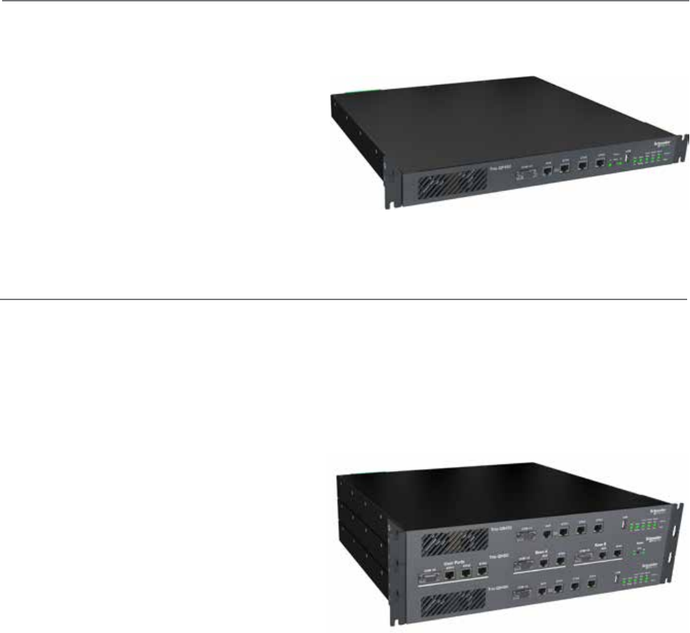
A, B, C & D hazardous locations UHF - Half Duplex Radio
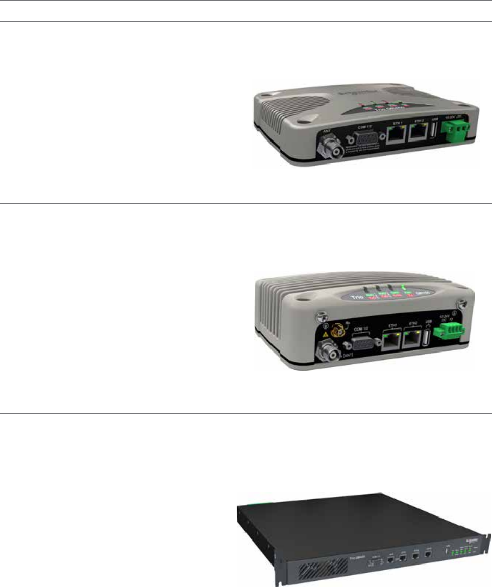
VHF - Half Duplex Radio
Q Data Radio Range
Part B – Feature Overview
• Simplex or Half duplex operation
• Small form factor, rugged die cast housing
115 x 56 x 164 mm (4.52 x 2.2 x 6.45 in.)
• 10...30 Vdc supply voltage.
• DIN Rail Mounting Kit Option
(TBUMDIN-KIT-TYPEA)
• Suitable for use in Class I, Division 2, Groups
A, B, C & D hazardous locations
QR450 - UHF Half Duplex Radio
The QR450 Half Duplex Radio is ideal for remote applications as it has a smaller form factor, allowing the product to be
installed in space-restricted cabinets/enclosures. The QR450 can also be used as an Entry Point (Base/Master Station) or
repeater for systems with a small number of remotes where the transmitter duty cycle is low.
Features of the QR450 include:
QR150 - VHF Half Duplex Radio
The QR150 Half Duplex Radio is ideal for remote applications as it has a smaller form factor, allowing the product to be
installed in space-restricted cabinets/enclosures. The QR150 can also be used as an Entry Point (Base/Master Station) or
repeater for systems with a small number of remotes where the transmitter duty cycle is low.
Features of the QR150 include:
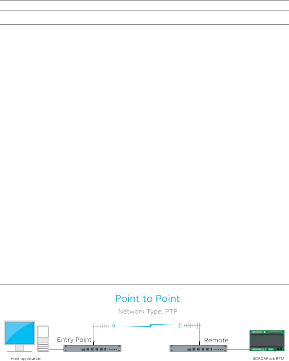
Full Duplex Base Radio
• Full Duplex operation (100% duty cycle)
• 19" 1RU rack mount
• Digital Inputs & Outputs
QB150 and QB450 - Full Duplex Radio
Complimenting the QR half duplex remote radios, is the QB full duplex radio, ideal for deployment at base & repeater sites in
systems using dual frequency operation. In high duty cycle applications, the QB delivers maximum rated transmitter power in
ambient temperatures up to 70°C (158°F). Where 1+1 hot standby redundancy is required, the half duplex QP and the full
duplex QH are available.
Features of the QB include:
11
Document Number: 0100SM1401 Issue: 12-16
Full Duplex Hot Standby Base Radio
QH150 and QH450 - Hot Standby Full Duplex Radio
Complimenting the QR half duplex remote radios, is the QH full duplex radio kit, ideal for deployment at base & repeater sites
in systems using dual frequency operation. In high duty cycle applications, the QH delivers maximum rated transmitter power
in ambient temperatures up to 70°C (158°F). Where 1+1 hot standby redundancy is not required, the full duplex QB base/
repeater station is available.
The features of the QH include:
• Full Duplex operation (100% duty cycle)
• Ethernet link monitoring and shared IP address
provides smart Ethernet redundancy
• Remote monitoring, control and changeover of
duplicated base/repeater stations
• Hot-swappable modular 19” rack mount
transceiver configuration (3 RU total)
• Automatic changeover upon alarm detection of
transmitter, receiver, data alarm detection, power
supply and data connectivity.
• Digital Inputs & Outputs
• Hot Standby Controller power supply
• 11...14 Vdc (from output of QBs)
• Max Current: 800mA
Part B – Feature Overview
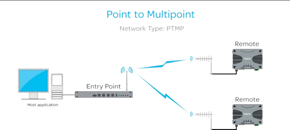
Half Duplex Hot Standby Base Radio
• Simplex or Half duplex operation
• Duplicated redundant transceiver configuration
• Automatic change-over
• 19" 1RU rack mount
• Digital Inputs & Outputs
QP150 and QP450 - Hot Standby Half Duplex Radio
The QP half duplex radio is ideal for deployment at base & repeater sites in systems using dual frequency (half duplex) or
single frequency (simplex) operation, where it will only be required to transmit OR receive. In high duty cycle applications, the
QP delivers maximum rated transmitter power in ambient temperatures up to 70°C (158°F).
The features of the QP include:
12 Document Number: 0100SM1401 Issue: 12-16
Part C – System Topologies & Operating Modes
Part C – System Topologies & Operating Modes
System Topologies
Introduction
Fundamental to understanding the use of the Q data radio range in your system is the need for a basic understanding of the
different types of radio system topologies and system topology functions.
System Topologies:
Point to Point (PTP):
• A system topology with two radios, one Entry Point and one Remote
Point to Multipoint (PTMP):
• A system topology with three or more radios, one Entry Point that directly communicates to two or more Remotes.
Point to Multipoint via a Repeater (PTMP/R):
• A system topology with three or more radios, one Entry Point that communicates via a repeater to two or more
Remotes.
Point to Multipoint via multiple Repeaters:
• A system topology with four or more radios, one Entry Point that communicates via multiple cascaded repeaters to
one or more Remotes.
Multipoint to multipoint (MPTMP):
• A system topology with one Entry Point and one or more remotes, and no repeaters, where remotes can talk directly
to the Entry Point or to each other.
• Only works with Simplex frequencies.
System Topology Functions:
Entry Point:
• The radio where user data enters the systems. Typically connected (directly or indirectly) to the Master RTU or SCADA Host.
Repeater:
• A radio which repeats data from an Entry point to Remote, or Remote to Remote, or Repeater to Repeater.
Remote:
• A radio which is the endpoint or perimeter of the system topology.
Each type of network is described in the following diagrams.
Point-to-Point (PTP)
A Point to Point (PTP) network has one Entry Point and one Remote radio. When full duplex radios are installed, full data
throughput can be achieved in each direction. Alternatively, half-duplex radios can also be implemented although collision
avoidance should be enabled.
Full Duplex radios have the advantage that they simulate a cable connection with respect to the connected devices. Even
if one device transmits continuously it will not block the other device from sending data. This is useful for applications that
expect full duplex communications or that are not designated to be radio modem friendly.
13
Document Number: 0100SM1401 Issue: 12-16
Point to Multipoint (PTMP)
A Point to Multipoint (PTMP) network is normally chosen when a central site (i.e.: The HOST application) needs to
communicate with multiple REMOTE sites.
Point to Multipoint (PTMP) operation requires the Entry Point site to have adequate RF coverage of all Remote sites. A PTMP
offers optimal available bandwidth and data latency when multiple remote sites are required.
In a multiple access radio system (MAS), communication occurs from a common site (the Entry Point) to all others, either
using a half duplex or simplex radio channel. In addition, remote sites can communicate to each for peer to peer messaging,
via the Entry Point.
For two frequency systems, to facilitate efficient data communication and support features such as digital collision avoidance,
it is recommended that the Entry Point be a full duplex radio (QB/QH).
Utilising a half duplex Entry Point radio is possible, however some features may not be available and system performance may
be lower when compared to using a full duplex entry point.
In most applications, this type of system topology is more efficient than other topologies.
Part C – System Topologies & Operating Modes
14 Document Number: 0100SM1401 Issue: 12-16
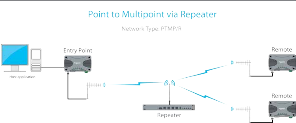
Point to Multipoint via Repeater (PTMP via Rep)
A Point to Multipoint via repeater (PTMP/R) network is a variation of the Point To Multipoint (PTMP) network. It is normally
chosen when the site where the Host application (i.e.: Entry Point) does not have adequate RF coverage of Remote sites in
the network.
This network topology consists of a radio configured as a Repeater (typically full duplex), an entry point radio and a number
of remotes. The repeater can be configured to repeat data based on either IP layer 2 (Bridge mode), or IP layer 3 (Router
mode) rules.
The repeater should be located at a site with adequate RF coverage to each of the remotes.
For two frequency systems, to facilitate efficient data communication and support features such as digital collision avoidance,
it is recommended that the Repeater be a full duplex radio (QB/QH).
Utilising a half duplex Entry Point radio is possible, however some features may not be available and system performance may
be lower when compared to using a full duplex entry point.
Other aspects of the Point to Multipoint network apply to this network topology.
Part C – System Topologies & Operating Modes
15
Document Number: 0100SM1401 Issue: 12-16
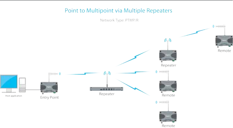
A PTMP via multiple repeaters system is a variation of the PTMP/R system. It is normally chosen when the site where the Host
application (i.e.: Entry Point) together with the first repeater have inadequate RF coverage of remote sites in the network.
In this system topology, there are multiple radios configured as repeaters. The PTMP/R with multiple repeater system
topology is only possible when using IP routing mode. Each repeater is configured to repeat traffic based on destination IP
address.
The repeaters should be located at sites with adequate RF coverage for the remote sites. For two frequency systems, to
facilitate efficient data communication and support features such as the collision avoidance mechanism, it is recommended
that the first Repeater be a full duplex radio (QB/QH).
Utilizing a half duplex Repeater is possible, however some features may not be available and system performance may be
lower when compared to using a full duplex entry point.
Other aspects of the Point to Multipoint network apply to this network topology.
Point to Multipoint via Multiple Repeaters (PTMP via multiple Reps)
Part C – System Topologies & Operating Modes
16 Document Number: 0100SM1401 Issue: 12-16
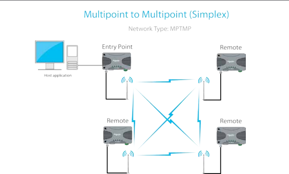
Flat Multipoint to Multipoint (MPTMP) - Simplex
A Multipoint to Multipoint network is a variation of the Point To Multipoint network. It is primarily used when the system
requirement is for each site to be able to communicate directly with every other site. This requires every site to have
adequate RF line of sight to every other site along with the use of simplex frequencies (Rx & Tx frequencies are the same).
In this system topology, each site typically require the use of an omni directional antenna. This is to provide an even spread of
antenna gain to and from each site.
Part C – System Topologies & Operating Modes
17
Document Number: 0100SM1401 Issue: 12-16
Operating Modes
Introduction
This section assumes the reader has an operational understanding of industrial Ethernet.
A typical Ethernet network consists of a number of IP devices, all which share the requirement of data communication. In
order for a pair of devices within an Ethernet based network to communicate with one another, they need to be able to
address data to a specific destination (in this case, each other).
MAC Address - MAC addresses identify Ethernet devices on a network when operating at Layer-2. All Ethernet ports in
devices have their own unique media access control (MAC) address. There are special MAC addresses used for broadcast
and Multicast messages.
IP Address - An IP address is a numerical label assigned to each device (e.g., Radio, RTU, SCADA Host) participating in a
computer network that uses the Internet Protocol for communication.
An IP address serves two principal functions:
• Host or network interface identification and
• Location addressing.
Subnet - A subnet is a subdivision of an IP network. It allows a network designer to segment a large IP network into
smaller, manageable sub networks. This can assist in the allocation of IP addresses and the management of network
bandwidth.
Subnet Mask - Together with the IP address, the subnet mask is used to determine which subnet a device belongs to.
Gateway - A gateway forwards IP messages between devices on different subnets in an IP network. A gateway uses
configurable routing rules to determine where to forward an IP message.
Route - A route is a rule that indicates where an IP message needs to be sent in order to get to a specific device on an IP network.
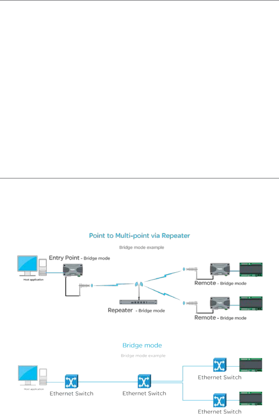
Transparent Bridge Mode
The Q data radios can be configured to operate in a transparent bridge mode. This mode transports all data as layer 2 Ethernet
traffic over the radio network. Each radio will behave like a layer 2 Ethernet switch, transparently forwarding traffic, based on
rules, dynamically determined from device MAC addresses. Traffic can also be repeated in any one single radio in the network
using a peer to peer repeat function (an enable/disable function, typically enabled in repeaters). Each radio requires an IP
address and mask to be configured in order for a user to access radio management features (web server/Telnet/diagnostics/
etc..). The example below shows a typical PTMP/R topology, with all radios operating in bridge mode.
From an IP network perspective, each radio within the topology above, effectively looks like an Ethernet switch. See the
example below.
Part C – System Topologies & Operating Modes
18 Document Number: 0100SM1401 Issue: 12-16
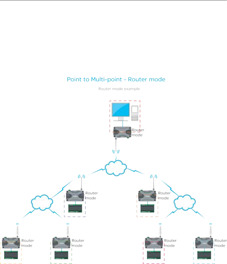
Router Mode
The Q data radios can also be configured to operate in router mode. Router mode provides the radio the ability to route IP
data, based on user configurable network routing rules (OSI model layer 3), between devices on different subnets.
The benefits of router mode include:
• Faster poll times
• Higher throughput
• Improved management of IP addresses
Each radio behaves as a network gateway for its corresponding subnet. This allows a network designer to segment a wide
area IP network (WAN) into smaller subnets, which minimises the amount of over the air radio traffic. Since each radio
behaves as a router, traffic will be routed (and repeated) based on user defined IP routing rules. The example below shows
how router mode segments an IP radio network into smaller subnets. Each radio has it’s own subnet, represented in the
example by dashed colored boxes.
Part C – System Topologies & Operating Modes
19
Document Number: 0100SM1401 Issue: 12-16
Part D – Feature Detail
Part D – Feature Detail
Hardware
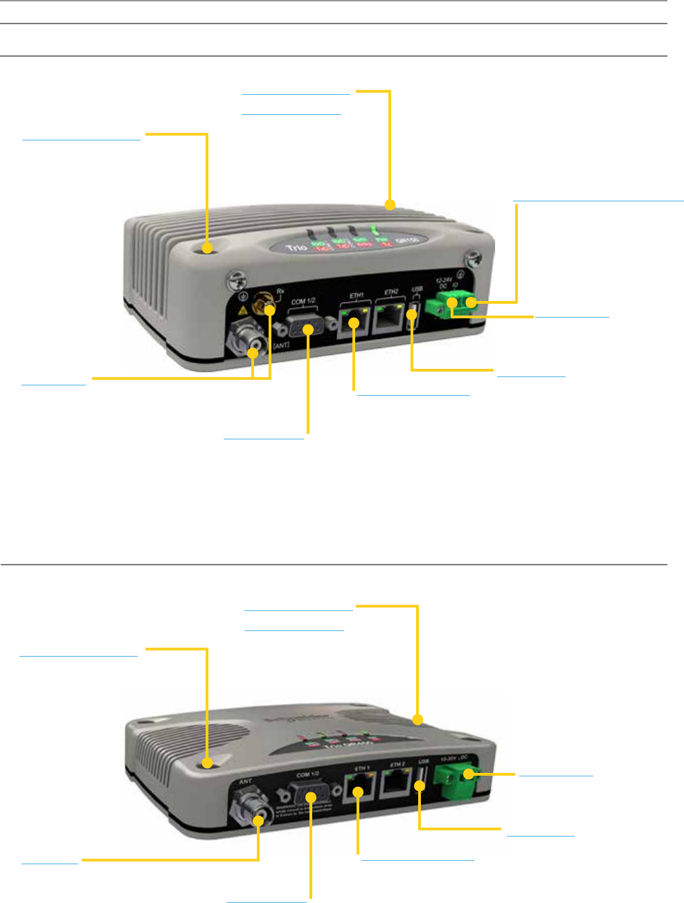
QR150 - Half Duplex Radio
QR450 - Half Duplex Radio
Mounting Holes
• Flat panel mounting
• DIN rail mounting
Diagnostics &
Management
• Status LEDs
• RSSI output
• Factory reset button
DC Power
• 10...30 Vdc
• 5 W standby
Ethernet Ports
• 2 x 10/100 MBps
• Auto MDIX Sensing
RF Port
• Up to 10 W RF power
• High VSWR foldback
• -40...70 oC (-40...158 oF)
• Over-temperature foldback
Serial Port
• Dual RS-232 Serial Ports
• Shared on single DB-9 connector
• Break-out cable if two ports required
• RS-485 mode supported
Mounting Holes
• Flat panel mounting
• DIN rail mounting
Diagnostics &
Management
• Status LEDs
• RSSI output
• Factory reset button
DC Power
• 10...30 Vdc
• 5 W standby
Ethernet Ports
• 2 x 10/100 MBps
• Auto MDIX Sensing
RF Ports
• User-configurable Single antenna
or separate Tx/Rx antenna.
• Up to 10 W RF power
• High VSWR foldback
• -40...70 oC (-40...158 oF)
• Over-temperature foldback
Serial Port
• Dual RS-232 Serial Ports
• Shared on single DB-9 connector
• Break-out cable if two ports required
• RS-485 mode supported
Digital Inputs/Outputs
• 2 pins dedicated as
digital inputs or outputs
• Read/Write Via SNMP
USB Port
• Load configuration files
USB Port
• Load configuration files
20 Document Number: 0100SM1401 Issue: 12-16
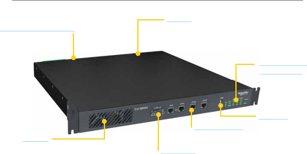
QB150 & QB450 - Full Duplex Radio
Digital Inputs/Outputs
• 3 DI / 3 DO
• Alarm Output
• Read/Write via SNMP
General
• 19 in. 1 RU Rack mounted
• -40...70 oC (-40...158 oF) @ 100% duty cycle
• Full duplex operation
• Temperature controlled fan-forced cooling
Diagnostics &
Management
• Status LEDs
• RSSI output
• Factory reset button
Ethernet Ports
• 3 x 10/100 MBps
• Auto MDIX Sensing
RF Port
• Up to 10 W RF power
• Separate Tx/Rx connections
• High VSWR foldback
• Over-temperature foldback
Serial Port
• Dual RS-232 Serial Ports
• Shared on single DB-9 connector
• Break-out cable if two ports required
• RS-485 mode supported
USB Port
• Load configuration files
Part D – Feature Detail
21
Document Number: 0100SM1401 Issue: 12-16
ARQs
Automatic Repeat reQuests (ARQs): When enabled, ARQs confirm successful reception of data transmitted over the air.
Each time a radio (originator) transmits data, the receiving radio replies with an acknowledgement back to the originator,
confirming successful reception of the data. If an acknowledgement is not received by the originator within an acceptable
time frame, the originator declares the data lost and retransmits the data. The number of retransmit attempts is user
configurable (i.e. when ARQ = 2, there will be a maximum of two retransmit attempts per message).
When Ethernet data is not successfully transmitted over a radio network (i.e. due to a data collision), Ethernet devices can
interpret this as network congestion, resulting in unnecessary slow down of SCADA polling. ARQs increase the probability of
successful transportation of data over the radio link. However, when ARQs are enabled, the capacity of the radio network is
reduced, due to the ARQ acknowledgements. As only one device can generate an acknowledgement for received data, ARQs
are not applicable to broadcast or multicast traffic
The Trio Q data radios use continuous phase
modulation (CPM) which supports up to 10
Watts of transmitter output power, even at the
fastest RF data rate.
This avoids the need to compromise on range
when operating at the fastest speeds. Two
different radio variants and modulation types
are available, depending on the regulatory
requirements (FCC or ACMA/ETSI).
• TBURQxxxx-E00xxxxxx: ‘E’ denotes ACMA/ETSI
• TBURQxxxx-F00xxxxxx: ‘F’ denotes FCC
Contact your local sales representative if you
need to confirm the applicable model for your
regulatory region.
Efficiency and Bandwidth
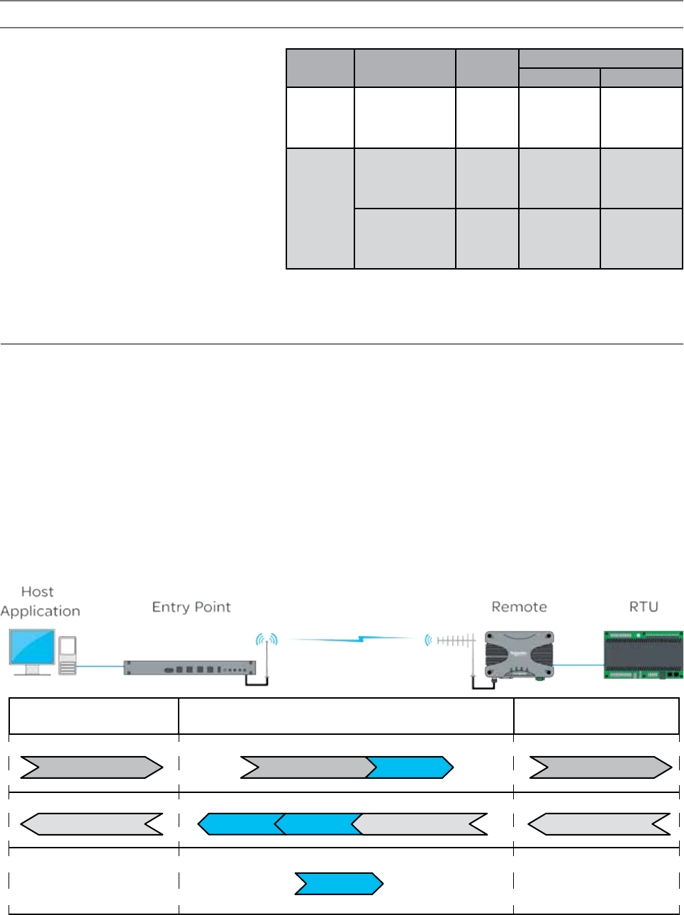
Host Application to Entry
Point
Entry Point to Remote Remote to RTU
SCADA POLL SCADA POLL SCADA POLL
ARQ ACK
(ARQ flag enabled)
RTU RESPONSE RTU RESPONSE RTU RESPONSE
(ARQ flag enabled)
ARQ ON
Typical data transaction with ARQ enabled
ARQ ON
ARQ ACK
The example below shows the ARQ behavior between a pair of radios during a typical data transaction.
Part D – Feature Detail
Regulatory
Region
Channel
Bandwidth (KHz)
RF Speed
(Kbps)
BER threshold (10^6)
VHF (150) UHF (450)
FCC/IC
12.5
8
16
24
32
-113
-111
-108
-100
-113
-110
-107
-100
ACMA/
ETSI
12.5
8
16
24
32
-113
-111
-108
-100
-113
-110
-107
-100
25
14
28
42
56
-109
-107
-105
-98
-111
-109
-106
-99
RF Speeds and Sensitivity
22 Document Number: 0100SM1401 Issue: 12-16
Host Application to Entry
Point
Entry Point to Remote Remote to RTU
SCADA POLL
SCADA POLL
ARQ ACK RTU RESPONSE RTU RESPONSE RTU RESPONSE
SCADA POLL Lost
ARQ ON
Automatic Retry Example
ARQ ON
ARQ ACK
The example below shows the ARQ behavior between a pair of radios when a packet is lost during a transmission (ARQ =1).
SCADA POLL
Acknowledgement wait time
ARQ ON
SCADA POLL
(Automatic Retry)
The radio will wait 500ms for an acknowledgement, before sending an automatic retry. It is recommended
that the SCADA host poll response time out time is configured to be a minimum of 3 seconds.
Part D – Feature Detail
23
Document Number: 0100SM1401 Issue: 12-16
Dynamic Speed Selection
Traditional narrow band SCADA data radios achieved wireless communication over long distances by transmitting at low
RF data rates (typically 9600bps or less). Modern SCADA systems require faster RF data rates, due to the need to support
additional traffic for Ethernet and IP. However, reliable transmission over long distances at faster RF data rates, can be difficult
to achieve.
To assist in reliable data transmission over long distances at faster RF data rates, the Trio Q data radios utilise dynamic speed
selection. Dynamic speed selection provides the following enhancements:
• Operation at the fastest possible RF speeds
• Measurement of Quality of Service - QoS (success of data delivery to other end) and
• Automatically adjusting to a slower RF speed to improve quality, if QoS is inadequate
Dynamic speed selection is individual for each remote in a point to multipoint (PTMP) system. Should one remote need to
operate at a slower RF speed due to limited received RF signal, others will continue to operate at the fastest possible RF
speed as dictated by their own received RF signal strength for that specific site.
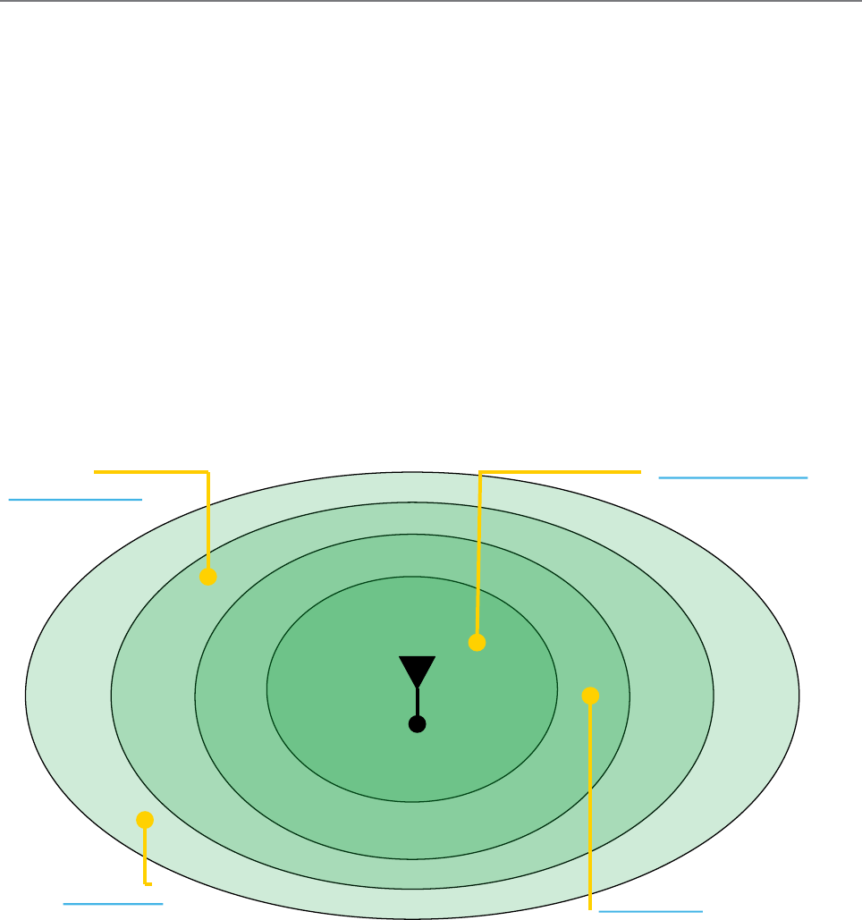
RF Data Rate vs RF Sensitivity
As stated earlier in this section, Trio Q Data Radios have four different RF speeds for each channel bandwidth selection
(12.5kHz or 25kHz). Each RF speed has a corresponding receiver 1 x 10⁻⁶ BER (Bit Error Rate) sensitivity. The slower the RF
speed, the better RF sensitivity, and therefore the longer the range for a given level of reliability.
Very High Speed
High Speed
Medium Speed
Low Speed
Dynamic Speed Selection Example
The further away from the master station, the weaker the received signal.
Slower RF speeds are required for an acceptable level of reliability
Tx
The further away from the master station, the weaker the received signal. Slower RF speeds are required for an acceptable
level of reliability.
Consider the example shown in the diagram above. An entry point / base station is located in a fixed position. When
communicating with a remote radio, RF energy between the two radios diminishes in strength as the signal propagates over
distance.
Part D – Feature Detail
In a system with out dynamic RF speed selection, the user would need to configure a suitable fixed RF speed, dependent on
the signal strength at the remote site. In most applications, a minimum of 20dB fade margin is recommended for reliable
operation (due to rain fades, cable degradation, multipath fading, etc). If the remote radio is fixed at a specific RF speed,
then in order to maintain a received signal 20dB above the 1E-6 BER sensitivity (20dB fade margin), the user would need to
decrease the RF speed when the receiving radio is further away from the transmitter. This is depicted in the diagram above
by the concentric rings showing what RF speed can needs to be selected in order to maintain a 20dB fade margin.
24 Document Number: 0100SM1401 Issue: 12-16
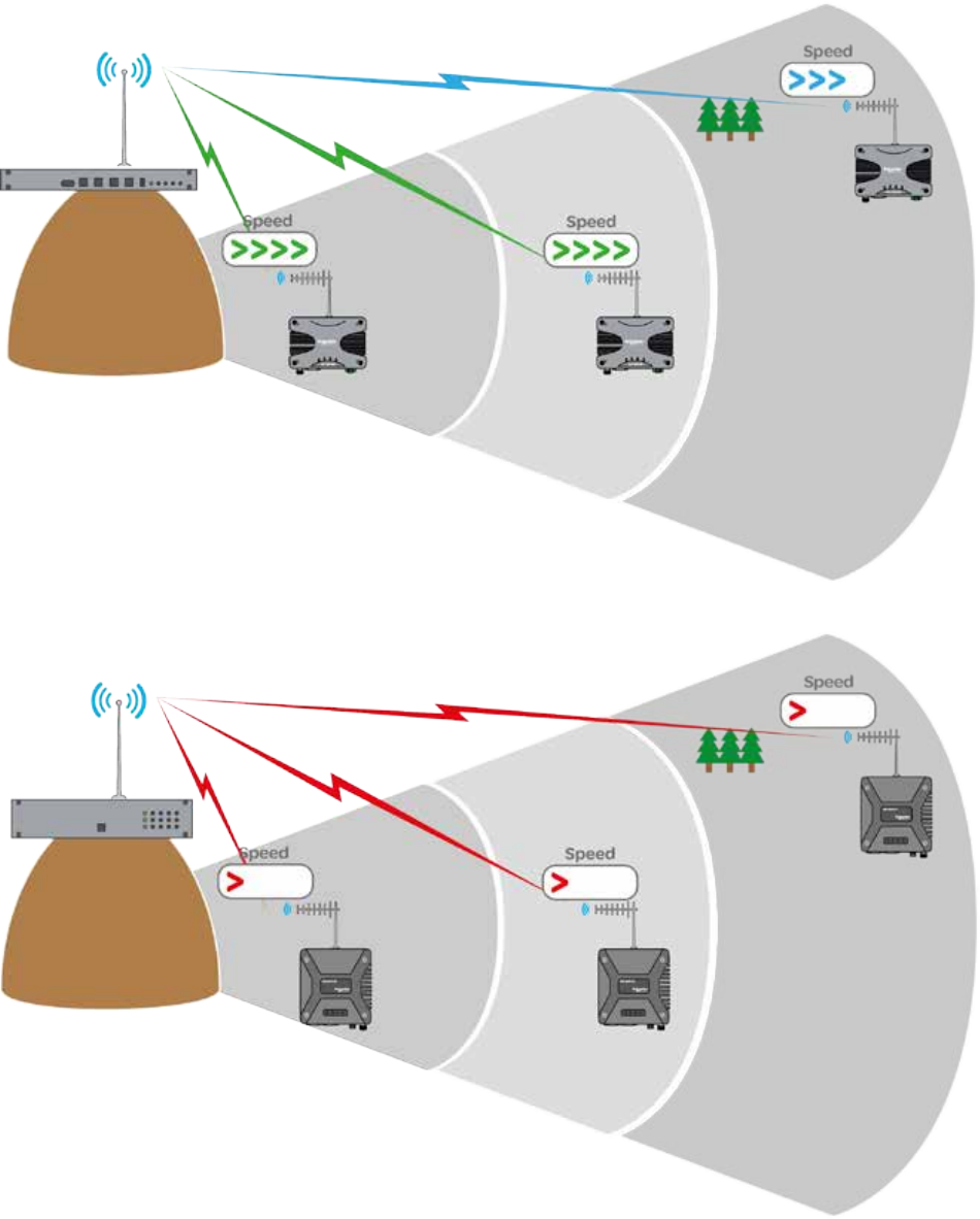
Consider now, in the below example where dynamic RF speed selection is enabled. Now that the receiving radio can adjust
its RF speed dynamically, a faster RF speed can be chosen for normal operation. Even though the faster RF speed will not
provide 20dB of fade margin, the system is still reliable because dynamic speed selection will drop down in RF speed when a
signal fade occurs.
Part D – Feature Detail
• Multiple different RF speeds can be
utilised simultaneously, as dictated by
the site distance from the base station.
• Each site will operated at the fastest
possible RF speed.
• Older technology can only operate at the
same fixed RF speed, normally dictated by
the site requiring the longest range.
• All other sites are compromised by having
to operate at the slower RF speed
Dynamic Speed - No Obstructions
Old Technology - No Obstructions
25
Document Number: 0100SM1401 Issue: 12-16
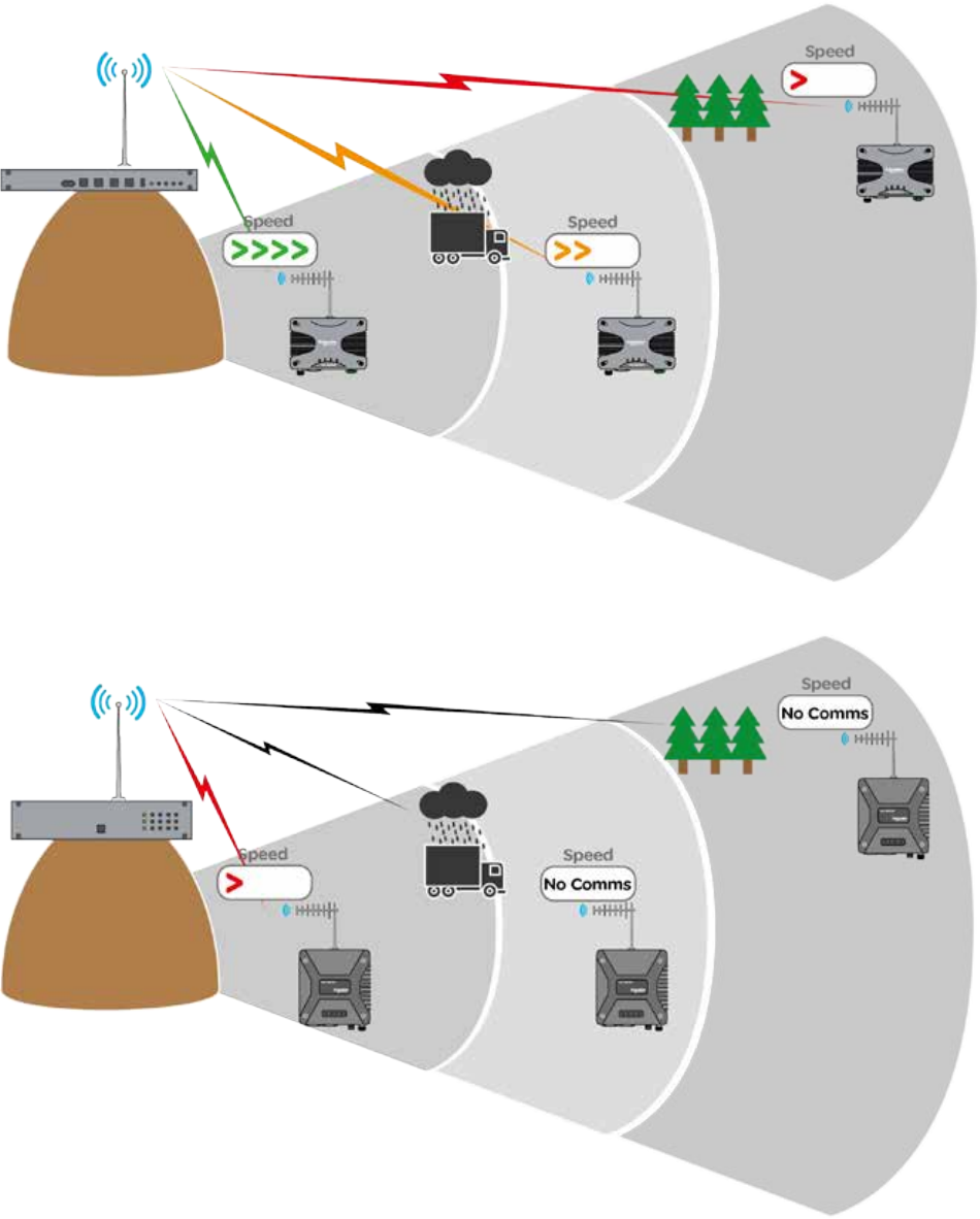
• Radios which detect reduced QoS
(Quality of Service) can increase
reliability by dynamically reducing
their RF speed to the base station.
• Sites which are not impacted by
reduced QoS remain unchanged.
• Older technology does not have the
ability to monitor the radio link QoS
or dynamically adjust the over the air
data rate, which can result in loss of
communications.
Part D – Feature Detail
Dynamic speed selection derives QoS from both RSSI (Received Signal Strength) and ARQ performance in order to maintain a
radio link operating at the fastest speed possible for the given quality of the link.
Each radio stores a table of destination MAC addresses vs fastest RF speed in a dynamic speed cache, using information learned
from previous transactions over the air. In this way, the radio dynamically learns what RF speed should be chosen for a transmission.
Should the transmission generate an ARQ, the radio will drop down in RF speed to improve reliability of data delivery.
In the event that radio has not yet learnt the fastest RF speed for a destination MAC, the message will be transmitted out at
the slowest RF speed in the given bandwidth, to provide the highest sensitivity, and therefore the highest reliability.
As broadcast and multicast addresses are potentially destined for multiple radios these types messages will always be
transmitted at the slowest speed. The following diagrams show how the RF data rate can be influenced by obstructions:
Dynamic Speed - With Obstructions
Old Technology - With Obstructions
26 Document Number: 0100SM1401 Issue: 12-16
Dynamic Speed Cache
The dynamic speed cache is used by a radio to record specific external values that are learnt. These values are then used by
other processes within the radio (such as dynamic speed and ARQ) to help ensure that optimum performance is achieved
over the radio channel.
External values that are learnt are shown in the table below.
Remote Host MAC Associated Radio Serial Number RSSI level
Remote Host MAC: The MAC address of a device which is connected to a remote radio.
Associated Radio Serial Number: The Unique ID of a remote radio with which the Remote Host Device/MAC is associated with.
RSSI level: The signal strength received from the radio specified within the associated radio serial number field.
A typical data packet structure is shown below. (For the purposes of this example, the preamble, Ethernet type and CRC
fields have been excluded.)
Data packets sent over the air between radios have an additional field appended. An example is shown below.
Destination MAC Source MAC Datagram
Radio Headers
Source Radio
Serial Number ARQ Flag
Destination MAC Source MAC Datagram
Part D – Feature Detail
Consider now, in the below example where dynamic RF speed selection is enabled. Now that the receiving radio can adjust
its RF speed dynamically, a faster RF speed can be chosen for normal operation. Even though the faster RF speed will not
provide 20dB of fade margin, the system is still reliable because dynamic speed selection will drop down in RF speed when a
signal fade occurs.
Dynamic speed selection derives QoS from both RSSI (Received Signal Strength) and ARQ performance in order to maintain a
radio link operating at the fastest speed possible for the given quality of the link. The two influencing factors are:
Each radio stores a table of destination MAC addresses vs fastest RF speed in a dynamic speed cache, using information
learned from previous transactions over the air. In this way, the radio dynamically learns what RF speed should be chosen for
a transmission. Should the transmission generate an ARQ, the radio will drop down in RF speed to improve reliability of data
delivery.
In the event that radio has not yet learnt the fastest RF speed for a destination MAC, the message will be transmitted out at
the slowest RF speed in the given bandwidth, to provide the highest sensitivity, and therefore the highest reliability.
As broadcast and multicast addresses are potentially destined for multiple radios these types messages will always be
transmitted at the slowest speed.
27
Document Number: 0100SM1401 Issue: 12-16
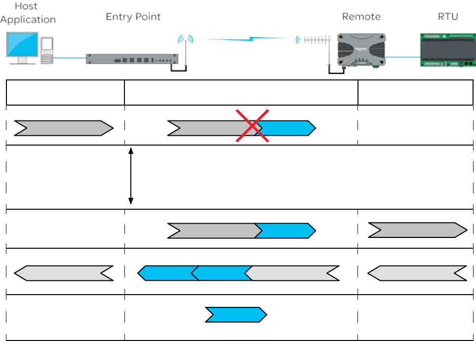
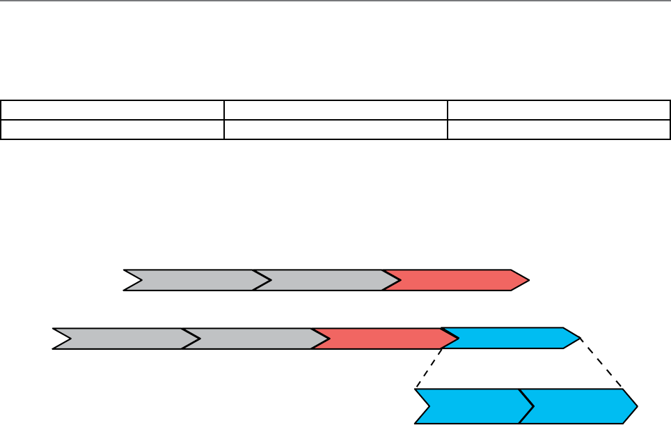
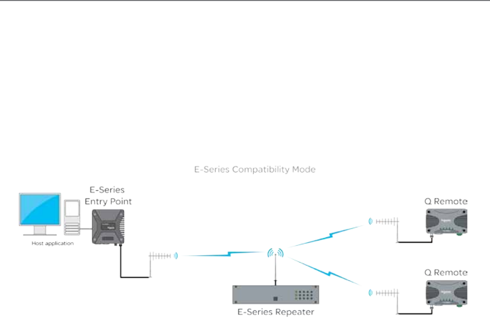
E-Series Emulation Mode
The Q data radios can be configured to operate in E-Series emulation mode. This can allow the replacement of existing
E-Series radio networks to be upgraded to Q data radio systems at a pace the user defines.
E-Series Emulation Mode can provide:
• A cost effective upgrade to a Q data radio network
• Minimise SCADA connectivity downtime during an upgrade
• A greater subset of features once the radio network is fully upgraded, as E-Series emulation mode is a user
configurable feature.
The diagram below shows how an existing E-Series radio system can be progressively upgraded to a Q data radio system by
replacing E-Series radios ‘One by One’ with Q data radios operating in E-Series emulation mode.
Once all E-Series have been replaced, the Q data radios may be re-configured to operate in Q mode, to provide advanced
features and functionalities of the Q data radios.
Part D – Feature Detail

28 Document Number: 0100SM1401 Issue: 12-16
Introduction
In many SCADA and remote Telemetry applications, there exists the potential for over the air data collisions between radios.
This can occur when multiple asynchronous data traffic is present on the radio channel, such as SCADA polling, SCADA
exception reports, SNMP traps, pings and ARP requests.
In two frequency systems, collisions may occur on the receive channel of an Entry Point or Repeater radio, due to two or
more remotes transmitting simultaneously. If this occurs, the radio will receive a corrupted message from both radios and a
re-try will be required. Similarly, in simplex (single frequency) systems, collisions may occur on any receiving radio when two
or more radio transmit simultaneously.
In two frequency systems, collision avoidance minimises the chance of collisions by configuring one radio, as the collision
avoidance master, which informs remote radios when the master’s receive RF channel is busy. Remotes will check whether
the master is allowing access to the channel before a transmission occurs. If the channel is free, the remote will transmit. If
the channel is busy, the remote will buffer the message and execute a small random delay (in case multiple remotes have
data to send), then attempt to access the channel again. By avoiding collisions the SCADA system is able to operate more
efficiently, with fewer retries. Similarly, in simplex (single frequency) systems, remote radios can detect when the Entry Point
or Repeater radio is transmitting, and wait for it finish, before transmitting itself.
For two frequency systems, there are two different modes of collision avoidance:
• Carrier Detect - Remote radios in a carrier detect collision avoidance system, listen for a transmission (carrier)
from the collision avoidance master, to determine if the collision avoidance master is currently busy receiving a
transmission from another remote. When the collision avoidance master receives a transmission from a remote, it
activates its own transmitter, indicating to all other remotes that the channel is busy.
In this mode of operation, remote radios can not distinguish between the collision avoidance master transmitting data
and the collision avoidance master indicating the channel is busy.
Carrier Detect Mode can also be used without a collision avoidance master. This is typically implemented in simplex
systems, or systems with a small number of remotes.
• Digital - Remote radios in a digital collision avoidance system, monitor a channel busy flag in the digital data stream
transmitted from the collision avoidance master to determine if the collision avoidance master is currently busy
receiving a transmission from another remote. When the collision avoidance master receives a transmission from a
remote, it activates its own transmitter and sets the channel busy flag, indicating to all other remote the channel is
busy. However, unlike carrier detect mode, if the collision avoidance master needs to transmit data to remotes, it can
do so and clear the channel busy flag.
In this mode of operation, remote radios can distinguish between the collision avoidance master transmitting data and
the collision avoidance master indicating the channel is busy. Even if the collision avoidance master is transmitting
data, a remote radio can transmit data back to the collision avoidance master. In this way the radio system can fully
utilise the full duplex capabilities of the Entry Point or the Repeater (collision avoidance master). The channel busy
flag consumes a small amount of bandwidth in the collision avoidance master to remote direction. However, as this
direction is one to many, it has negligible impact on radio network capacity.
Digital can be used in two frequency, PTMP and PTMP/R system topologies where the Entry Point or Repeater is full
duplex. It is not available in simplex systems, or where the Entry Point/Repeater is half duplex or in PTMP via multiple
Repeaters system topologies.
Collision Avoidance
Part D – Feature Detail
29
Document Number: 0100SM1401 Issue: 12-16
Data waiting to be
transmitted
Is C/A busy
flag set?
No Transmit data to
C/A master
Yes
Wait a random
time
Collision avoidance operational examples:
Collision avoidance (C/A) has a number of user configurable parameters. These parameters work together with the specific
mode of C/A chosen to minimise the number of collisions on the radio channel. Interaction of these parameters in C/A is best
explained by reviewing the operational flow charts for common C/A configurations.
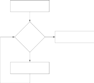
Digital Collision Avoidance Example 1
This flow chart shows the C/A operation in a remote
radio with the following configuration:
• C/A: Digital
• Backoff Method: Retry After Tx attempt
• Backoff time:
- Max Slots: 16
- Slot Time: 20ms
• Data Priority: Tx Data
As it is possible that there may be more than one radio waiting to transmit data to the C/A master, a random wait time is
applied, to avoid two radios waiting the same time, retrying and then colliding. There are multiple configurable parameters
involved in when the wait time is applied and what amount of time is waited.
• Backoff Method - Defines ‘when’ a radio will implement the backoff time. In this example, the backoff method is
configured to ‘Retry After Tx Attempt’. If the C/A busy flag is clear, the remote will transmit data immediately. If the
C/A busy flag is set, the remote will wait a random Backoff time and try again.
The Backoff time is calculated by choosing a random number between 1 and ‘Max Slots’ (in this example 16) and multiplying
the number by the ‘Slot Time’ (in this example 20ms). In any remote radio, a smaller number of ‘Max Slots’ and ‘Slot Time’
can be configured to reduce the random Backoff time, which will increase the rate at which the radio checks the C/A busy
flag. In effect, a radio with a smaller backoff time has a higher probability of transmitting its data first, in a situation where
multiple remote radios are waiting for access the channel.
As the data priority is configured for Tx Data, the radio will transmit data even when an incoming data packet it being
received.
This collision avoidance configuration provides maximum radio channel efficiency and are recommended when there is
multiple asynchronous data traffic on the radio channel.
When data is ready to be transmitted, the remote radio
checks the C/A busy flag to see if it is set (i.e. is the C/A
master receiver busy). If the C/A busy flag is clear, the
data is transmitted to the C/A master. If the C/A busy
flag is set, the radio waits a random time before trying
again.
Part D – Feature Detail
30 Document Number: 0100SM1401 Issue: 12-16
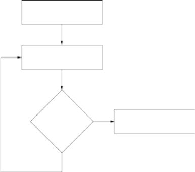
Digital Collision Avoidance Example 2
This flow chart shows the C/A operation in a remote
radio with the following configuration:
• C/A: Digital
• Backoff Method: Delay Before Tx attempt
• Backoff time:
- Max Slots: 16
- Slot Time: 20ms
• Data Priority: Tx Data
Data waiting to be
transmitted
Wait a random
time
Is C/A busy
flag set?
Transmit data to
C/A master
No
Yes
Rx data ‘Priority’:
In PTMP/R system topologies, where the Entry Point radio is half duplex, the configuration of Rx data priority may be required.
This is particularly useful for asynchronous traffic, such as a combination of SCADA exception reporting and polling. In this
scenario, the probability that a data packet currently being receive by the Entry Point radio is for the Entry Point radio and not
for a remote, is high. Therefore, without Rx data priority, incoming packets to the Entry Point radio would be lost if priority was
given to transmitting packets.
The primary difference when compared to example 1, is that the radio applies the random wait time before any attempt is
made to check the C/A busy flag.
This collision avoidance configuration provides maximum radio channel efficiency when there is synchronous data traffic on
the radio channel (i.e. GPS timing, synchronous exception reports) .
When data is ready to be transmitted, the remote radio
waits a random time before checking the C/A busy flag
to see if it is set (i.e. is the C/A master receiver busy). If
the C/A busy flag is clear, the data is transmitted to the
C/A master. If the C/A busy flag is set, the radio repeats
the wait time and tries again.
Part D – Feature Detail

31
Document Number: 0100SM1401 Issue: 12-16
Compression
The radio can apply compression to the payload of an IP packet, prior to transmitting it over the air. It can take upto 2 ms for
the payload to be run through the compressor. Generally, once the payload has run through the compressor, the payload
becomes smaller in size, reducing the amount of packets required to be transmitted, therefore, reducing over-all latency.
In some circumstance, the payload data can be ‘un-compressable’, meaning, once the payload has been run through the
compressor, the payload is mostly the same size it was to begin with. This results in no reduced packet size being sent over
the air, therfore, the time it took to run the payload through the comrpessor, will be added to the over-all latency. As this is
only approximatley 2 ms, it can be considered neglegable when compared with the over-all latency of the radio link.
The default and reccommended setting for compression is “Low”.
Ethernet Filtering
Ethernet filtering provides an easy to configure Layer 2 filtering mechanism, which can help prevent unnecessary Ethernet traffic
and increasing channel loading. There are various different addressing methodologies that can be filtered, which include:
Unicast:
Unicast is an addressing methodology that delivers messages to a single network destination
identified by a unique address.
Multicast:
Multicast is an addressing methodology that delivers messages to a group of destination addresses
simultaneously in a single transmission. Spanning tree messages are an example of multicast
messages.
Broadcast:
Broadcast is an addressing methodology that delivers messages to every device on a network. The
broadcast address of a device is calculated from the subnet mask. If all devices within a network use a
common network mask, the broadcast address will also be common.
Although typical SCADA applications only require Unicast & ARP data, the filtering mechanism provides the option to allow:
• All Ethernet traffic
• ARP + Unicast + Multicast (Although Spanning tree messages are multicast messages, they are also filtered out unless
the user is allowing all Ethernet traffic to pass. This also helps to prevent unnecessary channel loading.)
• ARP + Unicast (ARP is primarily used by networks to identify which physical devices own which IP addresses, Enabled
by default).
• Unicast only (Only used when a MAC address table is statically assigned).
• Or allow traffic from a single MAC address only.
Part D – Feature Detail
32 Document Number: 0100SM1401 Issue: 12-16
Connectivity
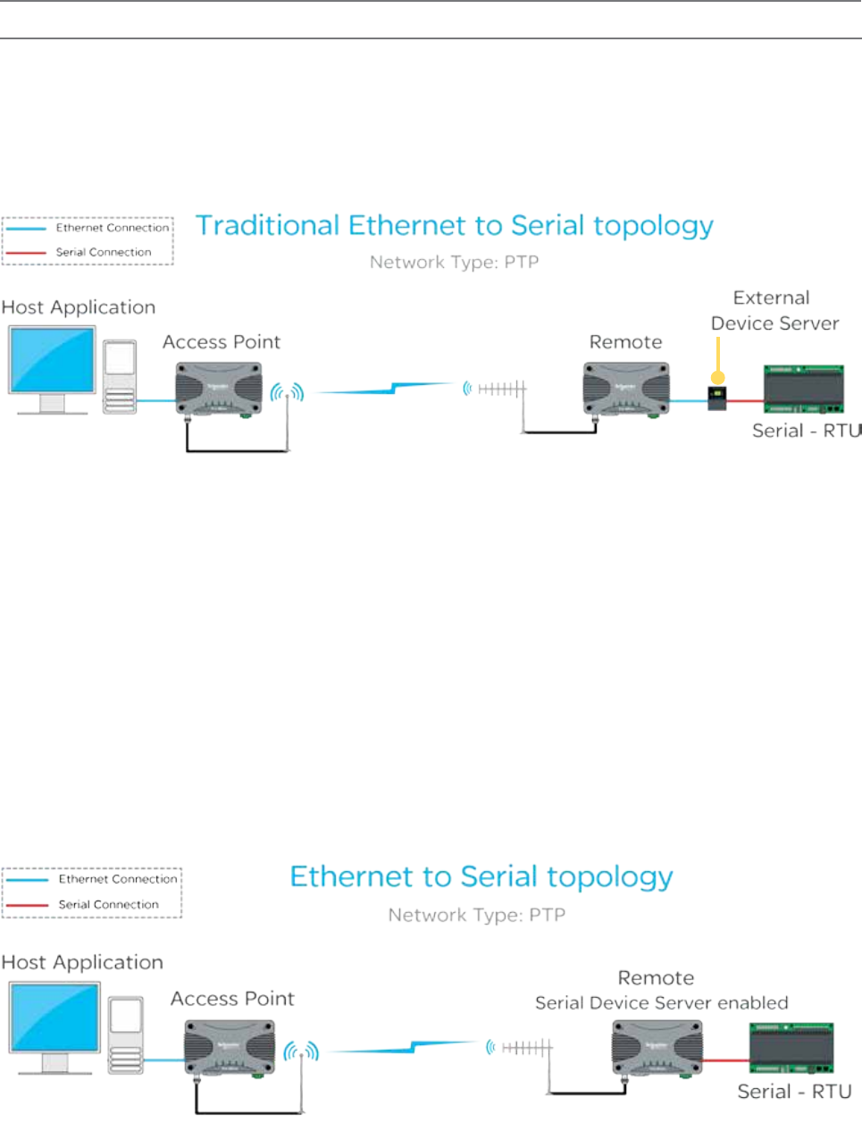
Embedded Serial Device Server
A serial device server can perform two tasks:
• Encapsulate serial data within IP headers to allow transportation of the serial data over a LAN/WAN.
• Take IP encapsulated serial data, strip off the IP headers and output the raw serial data.
Normally, systems require a standalone device server to integrate external serial devices at remotes sites into a managed LAN/
WAN. Q data radios provide the functionality of two embedded device servers which avoids the requirement for an external
device server. The example below shows a traditional IP radio, Ethernet to serial topology, using an external device server.
In a system that requires a serial connection to a remote end device and an Ethernet connection at the Host application end,
the device server should be enabled within the remote radio. When the embedded device server is enabled, the remote radio
provides the same functionality as if there was an external device server at the remote site. This functionality is also available
in a PTMP system.
Device Server mode provides an easily configurable mechanism for transporting serial traffic that does not have any built-in
addressing. The benefit of the device server feature is that device addressing can be performed using IP addresses for non-
addressable serial protocols, without the need for external terminal servers or managing serial devices using the IP address of
the remote radio.
Features of the embedded serial device server include:
• Support for two independent fully configurable serial device servers.
• Support for three transport protocols: TCP, UDP and PPP.
• Support for three modes of TCP operation: Client mode, Server mode and Client/Server mode.
• User-configurable port numbers.
• Support for up to 4 simultaneous TCP connections (sockets) when operating in server mode.
The diagram below shows a typical setup using the device server functionality in remote radios.
Part D – Feature Detail
33
Document Number: 0100SM1401 Issue: 12-16
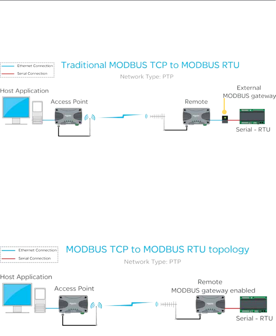
Embedded MODBUS Gateway
Q data radios have an embedded MODBUS Gateway feature that can be enabled to function like an external MODBUS
gateway. The MODBUS gateway is a protocol converter between MODBUS/TCP and MODBUS RTU protocols. The gateway is
an addition to the Device Server feature on the legacy serial port.
When operating in MODBUS gateway mode, the remote radio provides the same functionality as if there was an external
MODBUS gateway at each remote site of the system. In traditional systems, standalone MODBUS gateways were required to
convert the IP MODBUS TCP protocol to MODBUS RTU, the example below shows a traditional MODBUS TCP system using a
stand-alone MODBUS gateway at each remote site.
When operating in MODBUS gateway mode, the remote radio provides the same functionality as if there was an external
MODBUS gateway at each remote site.
Features of the embedded MODBUS gateway include:
• Support for two independent fully configurable MODBUS gateways.
• Support for two transport protocols: TCP and UDP.
• Support for two modes of TCP operation: Client mode and Server mode.
• User-configurable port numbers.
• Support for up to 16 simultaneous TCP connections (sockets) when operating in server mode.
MODBUS gateway mode provides an easily configurable mechanism for transporting serial traffic over an IP network (LAN/
WAN). A benefit of the MODBUS gateway feature is that the limitation of MODBUS addressing (0-255) can be ignored as
the IP address of the radio can be used giving unlimited addresses to external equipment such as RTUs or PLCs. Below is
an example of a typical system using the MODBUS gateway (remote) feature at each remote site to avoid the limitation of
MODBUS addressing.
Part D – Feature Detail
34 Document Number: 0100SM1401 Issue: 12-16
Network Address Translation (NAT)
Network Address Translation (NAT) provides a radio in IP routing mode, the ability to perform local port forwarding. Port
forwarding can be beneficial in a network where:
- An IP network has run out of available IP addresses.
- Multiple devices co-exist on a single IP network while sharing the same IP address.
In a standard IP routing radio network, each radio behaves as a network gateway to each of the local subnets. This type of
network consists of:
- A number of LANs: These are the subnetworks residing on the local side of each radio gateway. To subnet these
networks, each LAN requires a uniquely allocated IP range.
- A single Radio WAN: Each radio gateway is configured with a unique WAN address. This creates a subnetwork for the
radio channel.
NAT port forwarding can eliminate the requirement for unique addressing within the LAN subnets by translating the source
address of message sent from a device residing on the LAN with the address allocated to the radio router’s WAN network.
Devices residing on a local subnet will no longer be addressed by their unique IP address, rather, the IP address of the radio
gateway along with a unique port number.
When port forwarding is being configured, each IP device within a local network is allocated one port number on the radio
gateway and a port forwarding rule is entered into the gateway to define:
Gateway Listening Port - The port number which has been allocated to a single device on the radio gateways LAN.
When a message addresses this port number and forwarded to the radio gateway, the corresponding port forwarding rule will
be executed.
IP address and port number of the allocated device - When the Gateway Listening Port is addressed, the corresponding
rule is executed, where the message address will be translated to the IP address and port number defined in these rule
parameters.
Virtual LAN (VLAN)
VLAN can help provide isolation between separate entities who share a single network.
For example, Department A may require access to radio configuration/Diagnostics, while Department B may only requires
access to SCADA information. By implementing VLAN, a virtual network segregation can be implemented to help isolate each
of the departments from one another.
The following diagram shows managed switches placing separate hosts onto unique VLANs. Each remote has been
configured to use VLAN 1 on the ETH1 interface, which provides access to radio services, and VLAN 2 for the ETH2 interface
for SCADA control access.
Part D – Feature Detail
[VLAN 1] Network Management
[VLAN 2] SCADA Control
Un-Tagged packets
ETH1
Network
Management
SCADA
Control
ETH2
ETH2
Ethernet
Switch
WAN
Ethernet
Switch
ETH1 Optional connection for
radio system diagnostics
35
Document Number: 0100SM1401 Issue: 12-16
Ease of Use
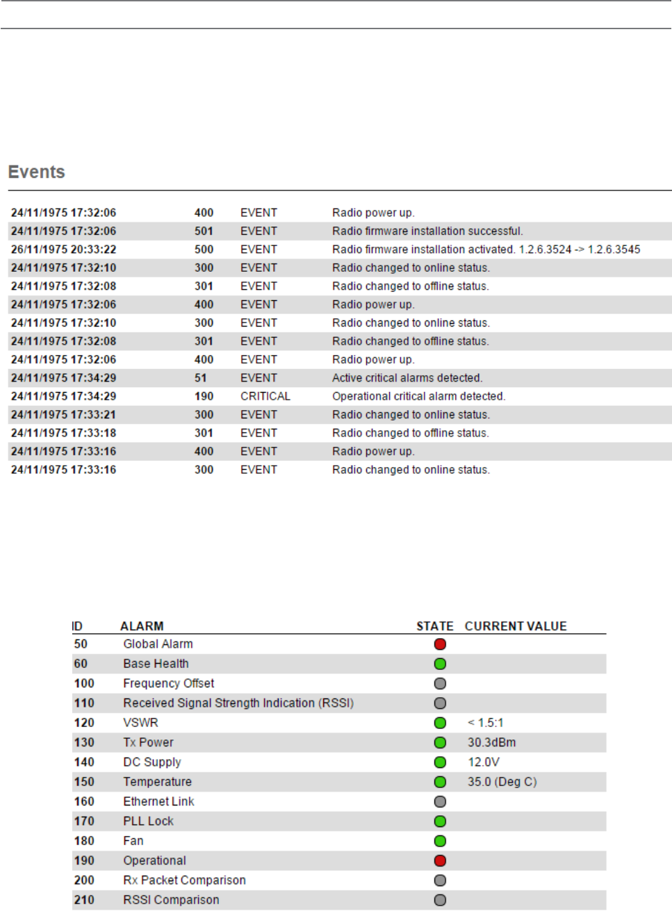
Alarms and Events
The Q data radio can be configured to monitor specific diagnostic values and raise alarms or record events (i.e DC volts, Tx Power,
etc). The radio’s active condition can be evaluated by observing the event history and alarm states.
Event History
The events window displays the history of each event that has occurred. Each event contains a time/date stamp, an event ID, the
severity level and a description of the event. Reviewing the event history can also help in fault diagnosis.
Alarm States
Alarms can be displayed in the following states: Disabled, Normal, Recovered, Warning or Critical.
Warning state thresholds for some alarms can be configured to best suit user requirements. This can provide early detection and
notification before an issue becomes critical (i.e. Damaged antenna, lost power/battery backup, etc).
Alarm state changes can also be subscribed to by notification services such as SNMP and digital outputs.
Part D – Feature Detail
36 Document Number: 0100SM1401 Issue: 12-16
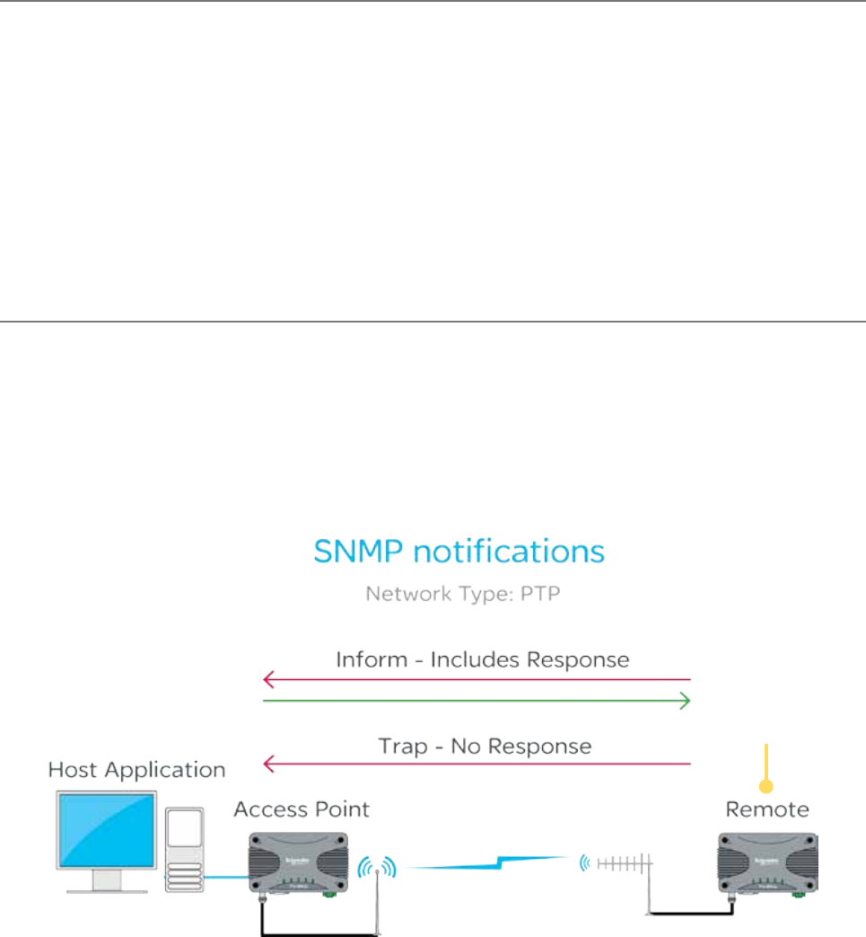
SNMP Diagnostics
The Q data radio can provide SNMP diagnostic data via an internal SNMP agent. The radio supports SNMP v1 & v2c along with
notifications which includes traps and informs. SNMP facilities include RFC1213, Ethernet diagnostics and radio diagnostics
The features and benefits of SNMP diagnostics include:
• SNMP messages/notifications that can be sent to Clear SCADA or SNMP management software.
• SNMP notifications that provide real time alarm detection reporting.
• Helping to eliminate the need for radio polling.
• Radios that can send diagnostic information via SNMP periodically (diagnostics heartbeat).
MIB files made available by Schneider Electric may be imported into most major SNMP Management consoles. These .MIB
files define the contents of the SNMP parameters including a description for each parameter. The parameters are sorted into
six distinct groups: General, Radio, Security, LAN, Error and Notification.
SNMP Notifications
The Q data radio have the capability to send SNMP notifications. An SNMP notification is a message to inform a user that
a radio state has changed. These states include: input voltage, temperature, Tx power, etc. There are two types of SNMP
notifications available: traps and informs.
• A trap is a single UDP message that is sent from the Q data radios to a user defined SNMP manger.
• An inform is still a UDP message, however, an inform requests a response to the UDP message sent. This allows retries
and time outs to be used within the radio.
QR that has fallen onto
battery backup voltage.
An SNMP notification has
been sent to the SNMP
management software.
Part D – Feature Detail
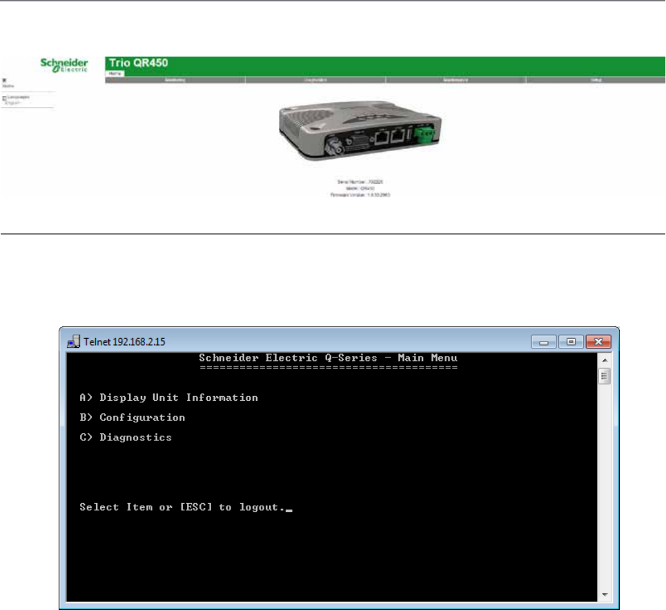
37
Document Number: 0100SM1401 Issue: 12-16
Web User Interface (WUI)
Q data radios provide a graphical Web User Interface (WUI) which can be accessed by a web browser to perform
configuration changes. This helps to eliminate the requirement for stand-alone configuration software to be installed on a PC.
Text User Interface (TUI)
The text user interface (TUI) provides an alternative to the HTML web user interface for configuration and diagnostics. The
TUI can be accessed directly from the serial port of the Q data radio or via a Telnet or SSH session. The TUI is enabled on
COM 1 by default, while Telnet is also enabled by default, however, this requires an Ethernet connection. Access to the TUI
via the serial port is useful if you have forgotten the IP address of the radio you are trying to configure or diagnose.
Part D – Feature Detail
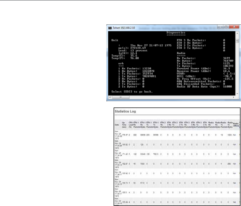
38 Document Number: 0100SM1401 Issue: 12-16
Diagnostics Tools
The Q data radios provide SNMP access to radio diagnostics as well as providing embedded (web) diagnostics and
commissioning features.
Radio Diagnostics:
The Q data radios include the ability for installers
to review useful radio & Ethernet diagnostics
parameters. The parameters include unit specific
(date & time), network specific (Ethernet traffic)
and radio specific parameters (Tx Power, DC volts,
etc). Diagnostics can be accessed via the web user
Interface or using the TVIEW+ Diagnostics suite (via
eDiags) or via serial console (COM 1 enabled by
default). Diagnostics can also be accessed via SNMP.
Statistics Log:
The Q data radios include the ability to measure and
record radio diagnostics and performance statistics
over a period of time. This facility is known as the
statistics log. The statistics log can be configured to
display/log data at a low, medium or high frequency
depending on a user’s requirements and can also be
saved to a CSV file for further analysis.
Part D – Feature Detail

39
Document Number: 0100SM1401 Issue: 12-16
Broadcast Firmware Upgrades
The TView+ Management Suite provides an over-the-air firmware update tool for Q Data radios. The firmware update feature
is speed-limited to help prevent RF channel congestion and can broadcast to all of the remotes within a Q data radio system.
Broadcasting to all remotes has the benefit of upgrading the alternative firmware pack in many radios simultaneously, without
the need to send firmware to each remote radio individually. Due to the speed-limiting of the firmware upgrade process,
SCADA data will not be blocked or interfered with while firmware packs are being transferred.
Each radio stores two sets of firmware. The current firmware pack is the firmware the radio is running from. The alternative
firmware pack is a secondary (optional) area where alternative firmware can be stored. When the alternative firmware pack
has been updated, it can then be activated which moves the alternative firmware into the current firmware pack area, and
causes the radio to reboot using the new firmware.
The firmware upgrade tool also provides the capability of individual activation or group activation, depending on user
preference. Firmware upgrades are typically done using “patch” files where only the difference between the current and
target firmware is actually sent. This reduces the over the air transmission of firmware data by up to 90%
See Part J for detailed information on this topic.
Packet Transmission Testing:
When commissioning a radio link, it is useful to generate Ethernet traffic to test the link for functional performance. One
method of generating traffic is using the “ping” utility provided on MS Windows based operating systems. Another method is
to perform a packet transmission test. This can be done using the “Packet Transmission Test” facility provided in the radio.
To perform the test, the user specifies the destination radio or Ethernet device IP address, number of packets to send, time
between packets (in milliseconds), packet length (in bytes), timeout and time between page refreshing. The test facility will
then execute the test and provide the results, which can then form part of the commissioning process.
Part D – Feature Detail
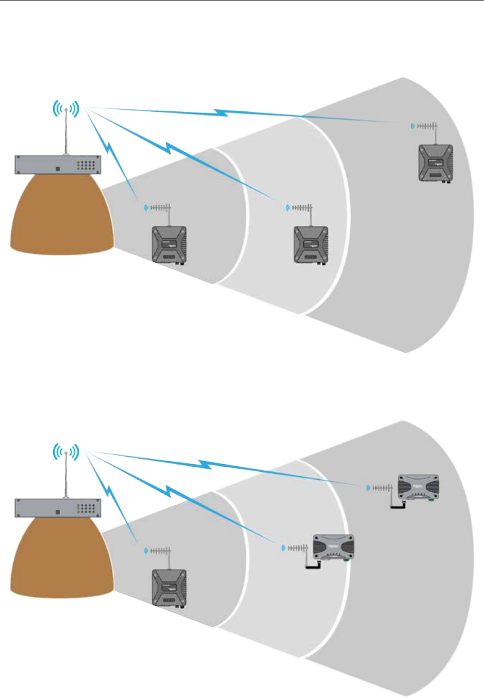
40 Document Number: 0100SM1401 Issue: 12-16
Trio E-Series Emulation Mode
Trio Q data radios can be configured to operate in E-Series mode. This can help a user to determine the length of time a full
system upgrade will take. See the examples below:
Typical E-Series system - Stage 1
The diagram below shows a typical E-Series system.
E-Series system upgrade - Stage 2
New installations or replacements of E-Series radios can be performed with Q data radios operating in E-Series compatibility
mode. This allows for a controlled and steady system upgrade. The diagram below shows Q data radios operating within an
E-Series system.
Part D – Feature Detail
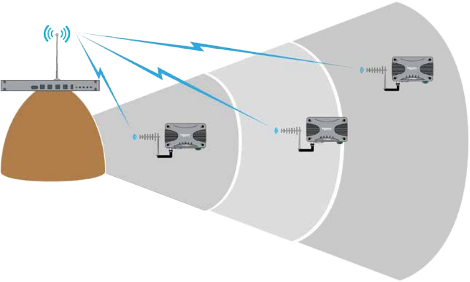
41
Document Number: 0100SM1401 Issue: 12-16
Switch system to Q Mode - Stage 3
Once all E-Series have been replaced, the Q data radios may be re-configured to operate in Q mode, to provide advanced
features and functionalities of the Q data radios.
Part D – Feature Detail
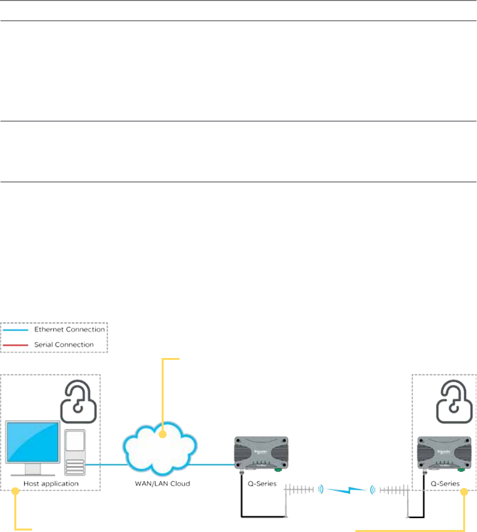
42 Document Number: 0100SM1401 Issue: 12-16
Unsecured Network
• SSH will help to prevent “man in the
middle” attacks over Insecure networks.
• All traffic between the client and TUI is
encrypted.
Network Management PC
• Running SSH client software (i.e. Putty) which
authenticates with the SSH server (i.e. remote
radio).
• Authentication occurs by comparing device
fingerprint with fingerprint stored in client’s register.
• Once the SSH server is authenticated, the SSH
client will establish an encrypted terminal session
with the TUI (Text User Interface) that allows for
configuration and diagnostics.
Remote Devices
• Embedded Secure Shell (SSH) server provides
access to the text user interface.
• Encryption will be used to communicate with an
SSH client during a configuration session.
• Once an SSH client has established a session to
the SSH server, the client will not be granted access
to the configuration until the pre-configured user
name and password has been entered.
Secure Shell (SSH)
SSH provides a secure and authenticated method for remotely accessing the Q data radios text user interface (TUI) for
configuration and diagnostics.
To access Q data radios via SSH, the network management PC requires an SSH-capable program (i.e.: Putty).
All traffic over the SSH connection is encrypted.
During the first connection to the SSH terminal software, a “fingerprint” of the remote device is taken and stored on the
Network Management PC. This allows for authentication in the future.
The SSH session also requires the user to enter a user name and password for authorised access to the TUI.
SSH example:
Security
Password protection and User Administration
Multiple users can be created and managed with different configuration privilege levels.
The different privilege access levels include: Unrestricted, Read/Write/Security, Read/Write, Read Only.
For more detail refer to Part H ‘User Administration’.
Configuration information can be protected by a user-defined login name and password. When a password is set, the
programmer will request the password each time the radio is read. No configuration information can be displayed or changed
without the entry of the correct password.
AES encryption
The 256-bit AES encryption feature can provide an encrypted channel that helps to prevent eaves-dropping and snooping.
The effort for configuration is minimal as the radio automatically adjusts, to keep packet transport compatible (i.e.: MODBUS
messages are not broken up). Enabling encryption requires additional overhead depending on packet sizes being sent.
Part D – Feature Detail
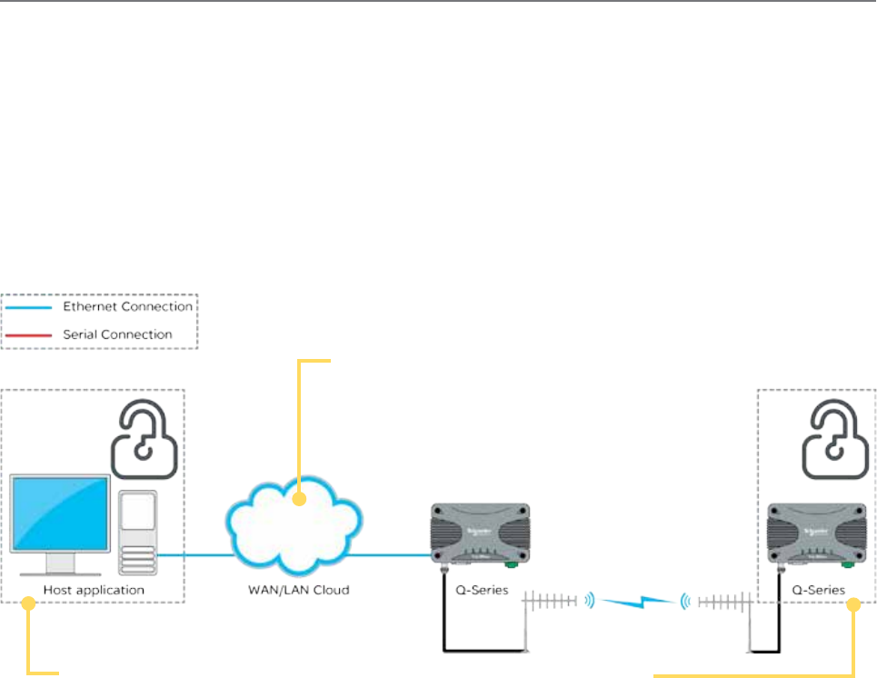
43
Document Number: 0100SM1401 Issue: 12-16
HTTP Secure (HTTPS)
HTTPS provides a secure and authenticated method for remotely accessing the Q data radios Web User Interface (WUI) for
configuration and diagnostics.
To access the Q data radios via HTTPS, use a web browser which has HTTPS capabilities. Common web browsers which
provide HTTPS capabilities include: Internet Explorer, Firefox and Chrome.
The HTTPS client (web browser) will request a digitally-signed certificate from the HTTPS server (Q data radios) to help
ensure that the target device is authentic.
All traffic over the HTTPS connection is encrypted.
Two methods of certificate management are available: Self-signed certificates generated by the radio itself or the use of
certificates generated by external certificate servers.
Unsecured Network
• SSH will help to prevent “man in the
middle” attacks over Insecure networks.
• All traffic between the client and TUI is
encrypted.
Network Management Server
• Using HTTPS Protocol, the Web Browser connects
to the target remote radio web server.
• The web browser uses digitally-signed certificates
to confirm the identity of the remote device.
• The web browser will have a list of trusted
Certification Authorities. If the Certificate is not
signed from a trusted CA, a message will be
displayed.
• Remote certificate is compared with local copy (or
with copy on certificate server).
• If certificates don’t match (or don’t exist) a
message is displayed.
• If certificates match then messages are not
displayed.
Remote Devices
• Remote devices can be configured to enable
HTTP and HTTPS separately.
• Certificates can be self-signed (generated by
the Q data radios radio itself) or 3rd-party
certificates can be used.
Part D – Feature Detail
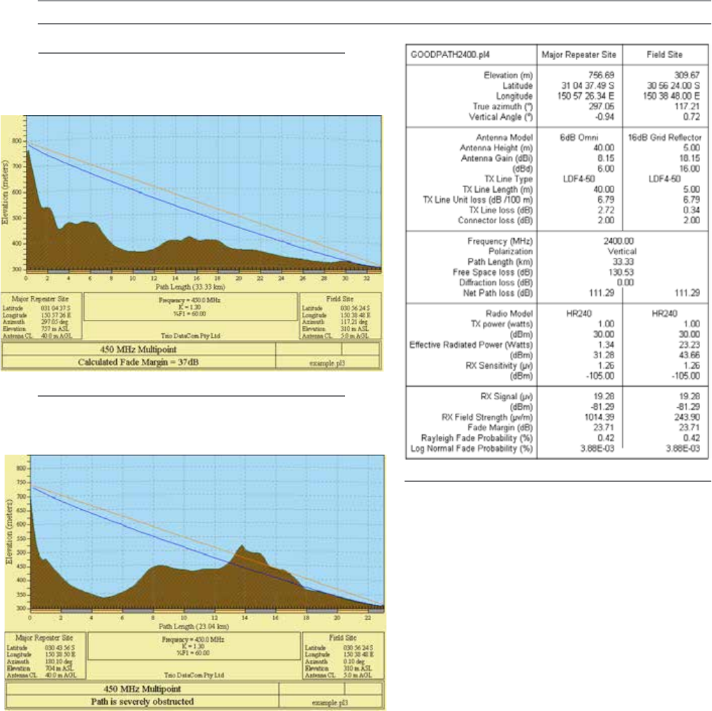
44 Document Number: 0100SM1401 Issue: 12-16
Part E – Radio Planning and Design
Part E – Radio Planning and Design
Obstructed Radio Path
This path has an obstruction that will reduce the signal
arriving at the field site.
Understanding RF Path Requirements
A radio modem needs a minimum amount of received
RF signal to operate reliably and provide adequate data
throughput.
In most cases, spectrum regulatory authorities will
also define or limit the amount of signal that can be
transmitted, and the transmitted power will decay with
distance and other factors, as it moves away from the
transmitting antenna.
It follows, therefore, that for a given transmission level,
there will be a finite distance at which a receiver can
operate reliably with respect to the transmitter.
Apart from signal strength reduction due to distance,
other factors that will decay a signal include obstructions
(hills, buildings, foliage), horizon (effectively the bulge
between two points on the earth), and factors such as
fog, heavy rain-bursts, dust storms, etc.
In order to ascertain the available RF coverage from a
transmitting station, it will be necessary to consider these
factors. This can be done in a number of ways, including
(a) Using basic formulas to calculate the theoretically
available signal - allowing only for free space loss
due to distance,
(b) Using sophisticated software to build earth
terrain models and apply other correction factors
such as earth curvature and the effects of
obstructions, and
(c) By actual field strength testing.
It is good design practice to consider the results of at
least two of these models to design a radio path.
Clear line of sight
Radio path with good signal levels, attenuated only by
free space loss.
Radio Path analysis
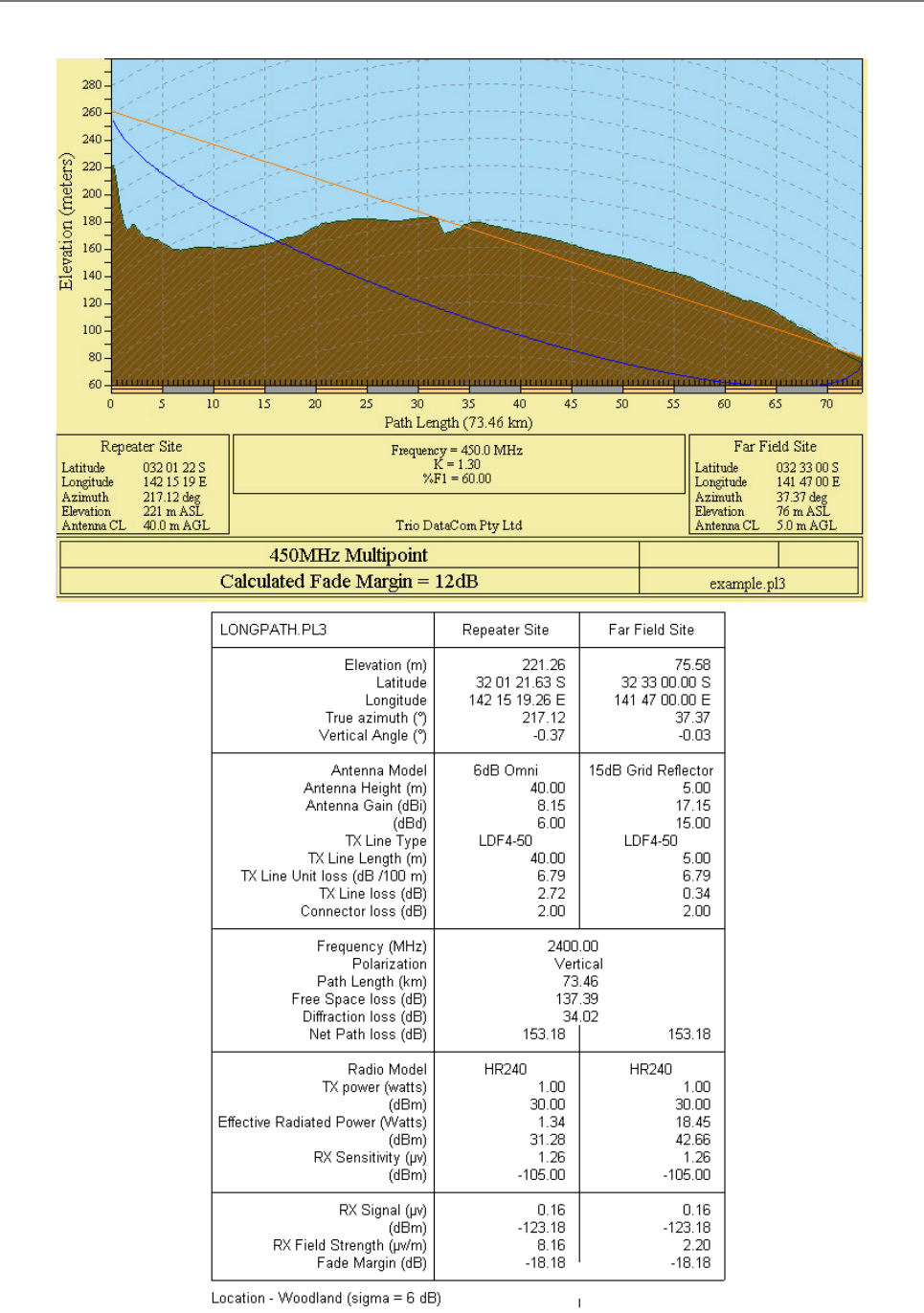
45
Document Number: 0100SM1401 Issue: 12-16
Effect of Earth Curvature on Long Paths
This path requires greater mast height to offset the earth curvature experienced at such a distance (73km).
Part E – Radio Planning and Design
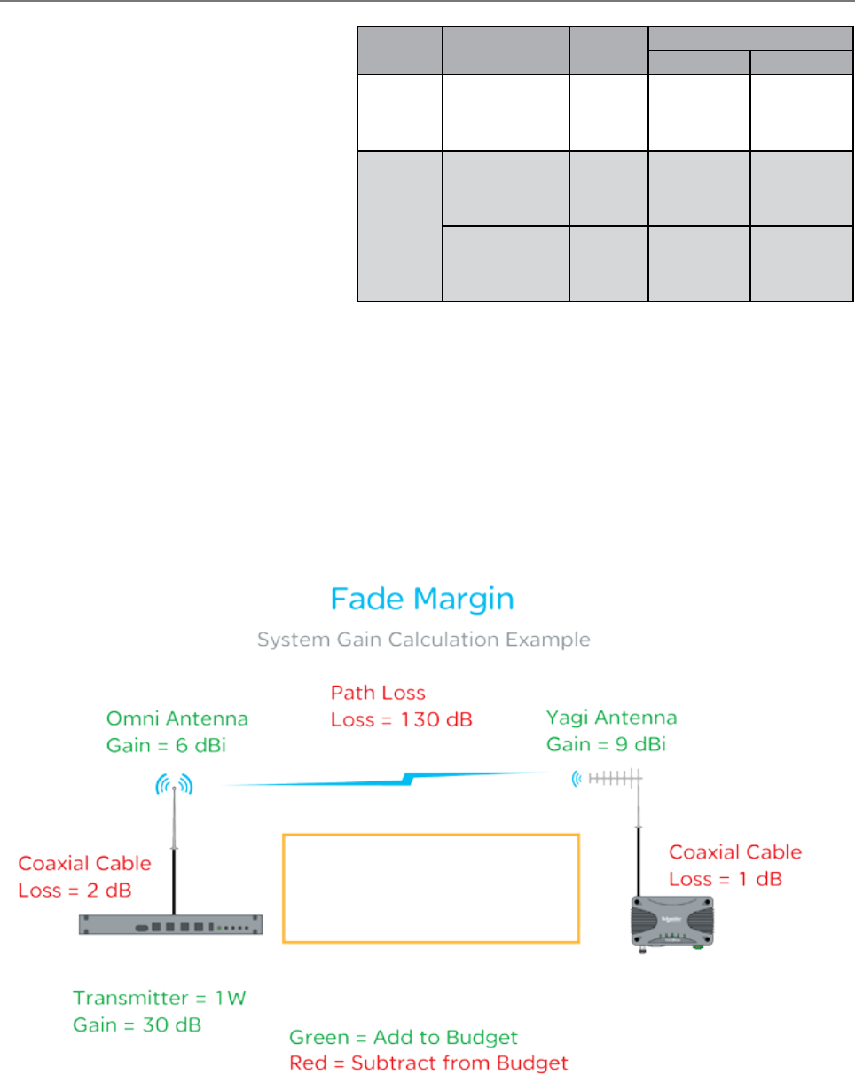
46 Document Number: 0100SM1401 Issue: 12-16
BER & Fade Margin
The BER specification used by the Q data radios
shows ‘1 x 10E -6 BER’. This means one bit of data
in a million bits of data will error at the BER threshold
level. The BER threshold values can vary depending
on the over the air data rate (RF speed). The BER
thresholds can be found in the table shown.
Fade Margin is the amount by which a received
signal level may be reduced without causing system
performance to fall below a specified threshold
value, in this case, the specified threshold value is
defined by the radio’s Bit Error Rate (BER).
20dB to 30dB fade margins are typical design
targets, however, 15dB may still be acceptable if
this is all that is possible.
Fade margin is required to maintain the radio link quality if the signal fades, factors that can influence signal fading include:
• Reflections
• Rain
• Maintenance Issues
When a Q data radio system is configured for Dynamic mode, the 20 dB (typical) fade margin calculation may be performed
using the lowest data rate, for best receiver sensitivity. (8 kbps in a 12.5 kHz channel or 14 kbps in a 25 kHz channel) This
helps to ensure that a strong reliable path when conditions are poor.
The amount of fade margin a radio link has can be calculated by performing a theoretical system gain calculation.
Factors that can influence system gain include: Tx power of Transmitting Radio, Coaxial Cable, Antenna Gains, Free Space
Loss, Rx sensitivity of receiving radio. See the example below.
The example is showing the factors within a radio link that can influence the signal strength of the transmitting radio at the
receiving radio (total system gain). Once the total system gain is calculated, the result is -88 dB. This means the received
signal strength (RSSI) at the receiving radio should be -88dBm.
As the BER threshold of the receiving radio is at -113 dBm, with an RSSI value of -88, the fade margin, before 1 bit in a
million bits of data become lost, is 25 dB. In other words, the RSSI level at the receiving radio can fluctuate up to -25 dB
before data loss may start to occur in over the air transmissions.
Part E – Radio Planning and Design
Total System Gain = -88 dB
BER = -113 dBm @ 10 ^ 6
Fade Margin = + 25 dB
Receiving Radio
BER = -113 dBm @ 10 ^ 6
Transmitting Radio
Regulatory
Region
Channel
Bandwidth (KHz)
RF Speed
(Kbps)
BER threshold (10^6)
VHF (150) UHF (450)
FCC/IC
12.5
8
16
24
32
-113
-111
-108
-100
-113
-110
-107
-100
ACMA/
ETSI
12.5
8
16
24
32
-113
-111
-108
-100
-113
-110
-107
-100
25
14
28
42
56
-109
-107
-105
-98
-111
-109
-106
-99
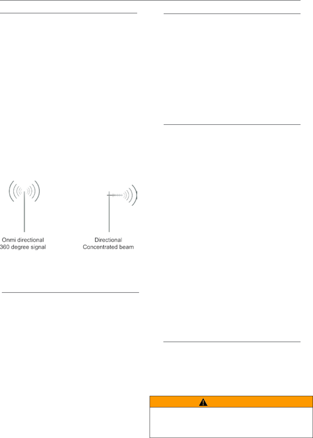
47
Document Number: 0100SM1401 Issue: 12-16
Radio Accessories
Antennas
Antenna Placement
When mounting the antenna, it is necessary to consider
the following criteria:
The mounting structure will need to be solid enough to
withstand additional loading on the antenna mount due to
extreme wind, ice or snow (and in some cases, large birds).
For Omni directional antennas, it is necessary to consider
the effect of the mounting structure (tower mast or
building) on the radiation pattern. Close-in structures,
particularly steel structures, can alter the radiation
pattern of the antenna. Where possible, Omni antennas
should be mounted on the top of the mast or pole
to minimise this effect. If this is not possible, mount
the antenna on a horizontal outrigger to get it at least
1-2m (3-6 ft) away from the structure. When mounting
on buildings, a small mast or pole, 2-4m (6-12ft) can
significantly improve the radiation pattern by providing
clearance from the building structure.
For directional antennas, it is generally only necessary to
consider the structure in relation to the forward radiation
pattern of the antenna, unless the structure is metallic,
and of a solid nature. In this case it is also prudent to
position the antenna as far away from the structure as is
practical. With directional antennas, it is also necessary
to ensure that the antenna cannot move in such a way
that the directional beamwidth will be affected. For long
YAGI antennas, it is often necessary to install a fibreglass
strut to stabilise the antenna under windy conditions.
Antenna Gain
By compressing the transmission energy into a disc or
beam, the antenna provides more energy (a stronger
signal) in that direction, and thus is said to have a
performance “gain” over a basic Omni antenna. Gain
is usually expressed in dBd, which is referenced to a
standard folded dipole. Gain can also be expressed
in dBi, which is referenced to a theoretical “isotropic”
radiator. Either way, if you intend to send and receive
signals from a single direction, there is advantage in
using a directional antenna - due to the increased signal
in the wanted direction, and the relatively decreased
signal in the unwanted direction (i.e. “Interference
rejection” properties).
There are basically two types of antennas –
omnidirectional and directional.
Omnidirectional antennas are designed to radiate signal
in a 360 degrees segment around the antenna. Basic
short range antennas such as folded dipoles and ground
independent whips are used to radiate the signal in a
“ball” shaped pattern. High gain Omni antennas such as
the “co-linear” compress the sphere of energy into the
horizontal plane, providing a relatively flat “disc” shaped
pattern which goes further because all of the energy is
radiated in the horizontal plane.
Directional antennas are designed to concentrate the signal
into a “beam” of energy for transmission in a single direction
(i.e. For point-to-point or remote to base applications).
Beamwidths vary according to the antenna type, and so can
be selected to suit design requirements. The most common
directional antenna is the YAGI, which offers usable beam
widths of 15-40 degrees. Higher “gain” is available using
parabolic “dish” type antennas such as gridpacks.
Connecting Antennas and RF Feeders
The RF antenna system should be installed in
accordance with the manufacturer’s notes. Consider
the antenna gain when setting transmit power on the
radio. EIRP limits will vary depending on your geographic
location. Check with your local authority to ensure that
you are abiding to the local laws.
Alignment of Directional Antennas
This is generally performed by altering the alignment of the
antenna whilst measuring the received signal strength. If the
signal is weak, it may be necessary to pre-align the antenna
using a compass, GPS, visual or map guidance in order to
“find” the wanted signal. Yagi antennas have a number of
lower gain “lobes” centred around the primary lobe. When
aligning for optimal signal strength, the antenna should be
scanned through at least 90 degrees, to help ensure that
the centre (strongest) lobe is identified.
When aligning a directional antenna, avoid placing hands
or body in the vicinity of the radiating element or the
forward beam pattern, as this will affect the performance
of the antenna.
WARNING
HAZARD OF RADIO FREQUENCY (RF) BURNS
Ensure that a matching load or antenna is attached to the RF port prior to
applying power to the device.
Failure to follow these instructions can result in death or serious injury.
Part E – Radio Planning and Design
Schneider Electric offers a variety of directional and omni-
directional antennas. For further information, refer to the
wireless accessories data sheet.
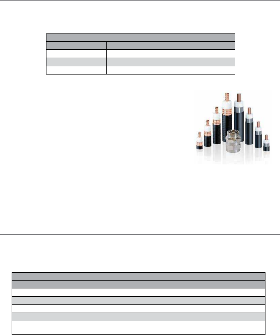
48 Document Number: 0100SM1401 Issue: 12-16
RF Coaxial Cable
There are many types of RF coaxial cables available, but it is sometimes difficult to
know which type of cable to use.
There are two main aspects of a cable to consider when selecting the right cable for
the job.
Bend Radius:
The bend radius of a cable is a specification given to a cable to define how flexible
the cable is. Exceeding the bend radius specification can change characteristics
within the cable and lead to reduced RF performance. The thicker the cable is, the
wider its bend radius will be, however, the thicker the cable, the lower its electrical
resistance will be, providing less impact on the radio system gain.
The cable connected from the radio to the lightning arrestor is typically quite short. This allows a thin, flexible cable to be
used. Thin flexible cables have a higher electrical resistance characteristic than thick rigid cables, but as there is only a short
length being used, the impact on radio system gain is negligible. The thick rigid cable is typically connected from the hut to
the top of an antenna mast connected to an antenna.
Antenna Feedline Cable Loss:
The antenna feedline cable supplies the connection between the radio and the antenna. When long lengths of cable are
required, it is important to factor-in the cable loss associated with length and type of cable being used.
Feeder Tail Cables
Typical installations use a thin, flexible RF cable, to interconnect the radio, to the outside of a hut/cabinet, these cables are
called ‘Feeder Tail Cables’.
Schneider Electric offers a variety of Feeder Tail Cables:
Part E – Radio Planning and Design
RF Adaptors
RF adaptors can be useful where, two connectors are not of the same type, however, need to be connected (i.e. an antenna
port of a radio and an RF lead which interconnects the antenna)
Schneider Electric offers a variety of RF adaptors:
RF Adaptors
Order Code Notes
TBUMRFAPT-TNCF-NM Trio RF Adapter TNC-Female to N-Male
TBUMRFAPT-TNCF-SMM Trio RF Adapter TNC-Female to SMA-Male
TBUMRFAPT-NF-NF Trio RF Adapter N-Female to N-Female - Flange Mount
Feed Tail Cables
Order Code Notes
TBUMRFJP-TNC-N-05M Trio RF Cable Feeder Tail 1.5Ft/0.5m - TNC-Male to N-Male
TBUMRFJP-TNC-N-1M Trio RF Cable Feeder Tail 3Ft/1m - TNC-Male to N-Male
TBUMRFJP-N-N-1M Trio RF Cable Feeder Tail 3Ft/1m - N-Male to N-Male
TBUMRFJP-SMA-N-1M Trio RF Cable Feeder Tail 3Ft/1m - SMA-Male to N-Male
TBUMRFJP-DUPLX-BP Trio Band Pass Duplexer Cable Kit 3Ft/1m - Double-Screened RF223/U with N-Male to N-Male.
(QTY of 2). Suits TBUMDUPLXBPxxx
49
Document Number: 0100SM1401 Issue: 12-16
Lightning Arrestors
A lightning arrestor is used to help minimise lightning damage to radio devices. Lightning arrestors are made to bleed off
electrostatic build-up to help prevent a direct lightning strike from hitting the antenna system. Also, if a lightning strike
happens nearby, the arrestor helps to route the energy to ground.
The lightning arrestor is typically installed on the inside of a radio hut, between a coaxial tail lead the antenna feeder cable.
The lightning arrestor comes with an N-Type female socket on each end.
Schneider Electric offers a variety of Lightning Arrestors:
Antennas Feedline Cable Loss characteristics
Cable Diameter
[order code reference]
150 MHz 450 MHz 900 MHz 2500 MHz
dB/100 ft dB/100 m dB/100 ft dB/100 m dB/100 ft dB/100 m dB/100 ft dB/100 m
10 mm (0.4 in.)
[TBUMRFANT-xxxxxx-A]
1.5 5.0 2.7 8.9 3.9 12.8 6.8 22.2
13 mm (0.5 in.) Heliax
[TBUMRFANT-xxxxxx-B]
0.8 2.7 1.5 4.8 2.1 6.9 3.6 12.0
Antenna Feedline Cables
Order Code Notes
TBUMRFANT-99F30M-B Trio RF Cable Antenna Feedline 99Ft/30m, 0.5in/13mm Heliax N-Male To N-Male (LDF4-50A or equivalent)
TBUMRFANT-75F22M-B Trio RF Cable Antenna Feedline 75Ft/22m, 0.5in/13mm Heliax N-Male To N-Male (LDF4-50A or equivalent)
TBUMRFANT-75F22M-A Trio RF Cable Antenna Feedline 75Ft/22m, 0.4in/10mm N-Male To N-Male (LMR-400 or equivalent)
TBUMRFANT-50F15M-A Trio RF Cable Antenna Feedline 50Ft/15m, 0.4in/10mm N-Male To N-Male (LMR-400 or equivalent)
TBUMRFANT-25F7M-A Trio RF Cable Antenna Feedline 25Ft/7m, 0.4in/10mm N-Male To N-Male (LMR-400 or equivalent)
TBUMRFANT-10F3M-A Trio RF Cable Antenna Feedline 10Ft/3m, 0.4in/10mm N-Male To N-Male (LMR-400 or equivalent)
Feeder Tail Cables
As the antenna needs to be mounted up high, a longer length of RF cable needs to run from the outside of the hut/
cabinet, to the antenna, this cable is called ‘Antenna Feedline Cable’.
Schneider Electric offers a variety of Antenna Feedline Cables:
As typical installations using antenna feedline cables use long lengths, it is important to consider the loss characteristics of
the cable being used, see the loss characteristics table below:
Lightning Arrestors
Order Code Frequency range Protected Side
Connector
Surge Side
Connector Mounting Style VSWR Notes
TBUMLT-ARRES-TYPEA 125 MHz to 1 GHz N-Female N-Female Bulkhead with right
angle bracket
1.1:1 Turn-on: 600 Vdc ±20%
TBUMLT-ARRES-TYPEB 2 to 6 GHz N-Female N-Female Bulkhead inline (no
bracket)
1.3:1 Surge: 10kA IEC 61000-
4-5 8/20μs waveform
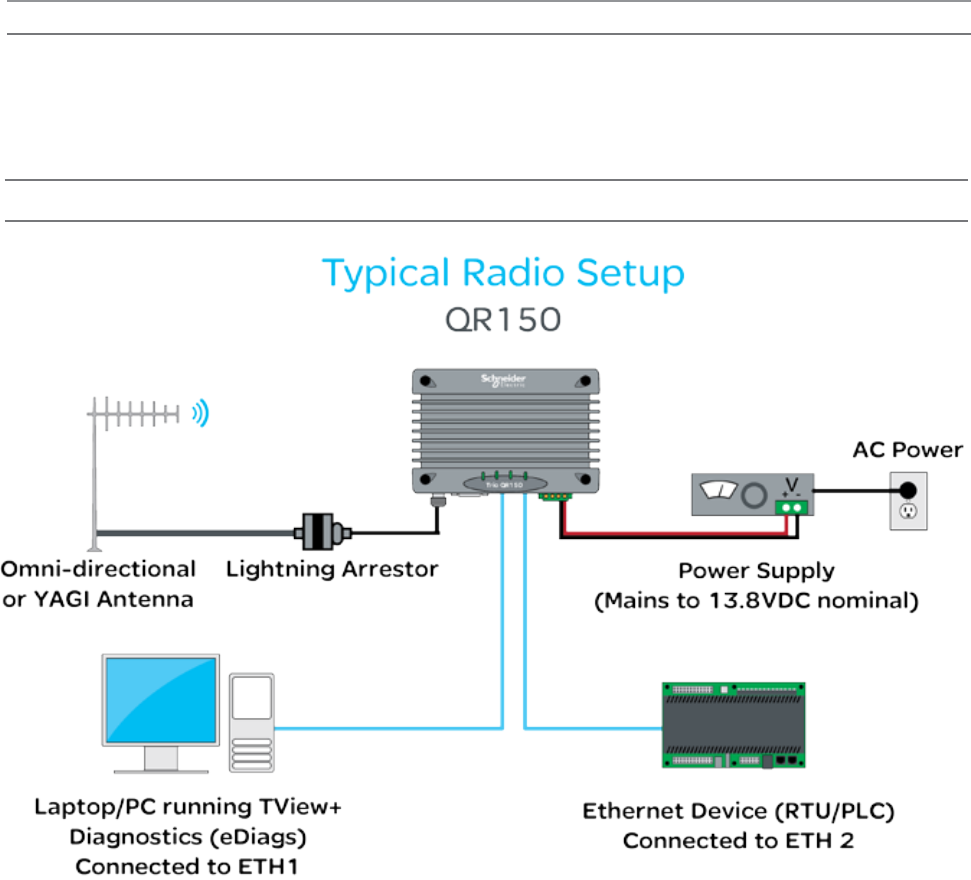
50 Document Number: 0100SM1401 Issue: 12-16
Part F – Quick Reference Guide
Welcome to the quick reference guide for the Q data radios. This guide provides general information on the physical
attributes of the Q data radios including, physical dimensions, mounting guides, LED indications and physical interface
connections.
Introduction
Part F – Quick Reference Guide
Half Duplex Radio - QR150
Typical Radio Setup
Schneider Electric offers a variety of wireless accessories, for further information, refer to the wireless accessories data sheet.
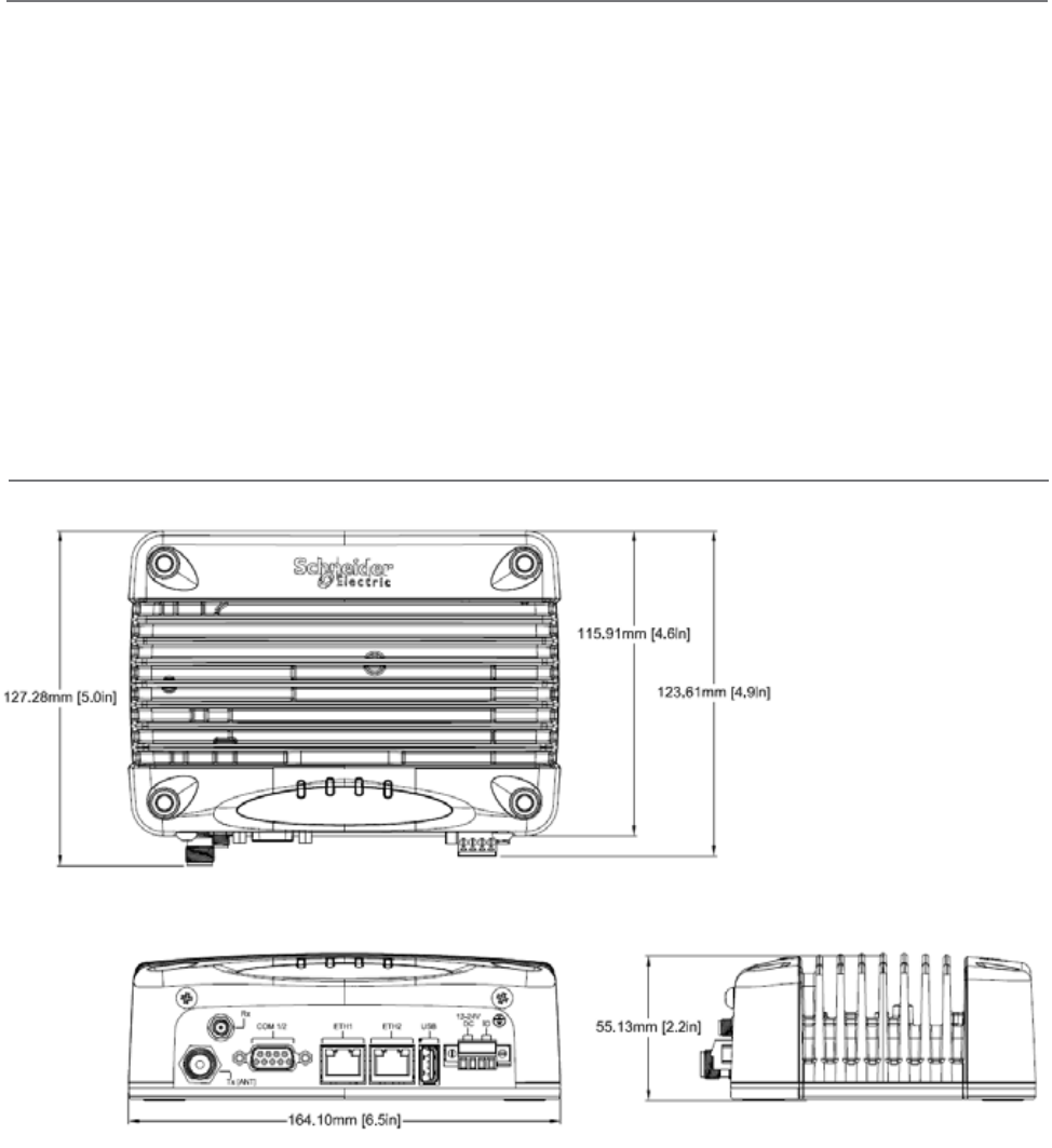
51
Document Number: 0100SM1401 Issue: 12-16
Part F – Quick Reference Guide
Mounting Instructions
Mount the radio in a clean and dry location, protected from water, excessive dust, corrosive fumes, extremes of temperature
and direct sunlight. In high power or high temperature applications, allow sufficient passive or active ventilation. To help
minimize moisture ingress it is suggested to mount the radio with the connectors facing downwards.
When mounting the equipment, consideration should be given to the environmental aspects of the site. The cabinet should
be positioned so that it is shaded from potential high temperature of the afternoon sun, or icy cold wind. Although the radios
are designed for harsh temperature extremes, they will give a longer service life if operated in a more stable temperature
environment.
In an industrial environment, the radio modems should be isolated from excessive vibration, which can destroy electronic
components, joints, and crystals. The cabinet should provide full protection from moisture, dust, corrosive atmospheres,
and residue from ants and small vermin (which can be corrosive or conductive). The radio modem will radiate heat from the
in-built heat sink, and the higher the transmitter duty cycle, the more heat will be radiated. Provide sufficient ventilation in the
form of passive or forced air circulation to help ensure that the radio is able to maintain quoted temperature limits.
The QR150 is designed with four mounting holes to allow a flat mount of the radio. Each QR150 comes standard with four
16mm x 40mm self drilling screws. The heads of these screws are low profile wafer heads with a no. 2 Phillips recess.
Physical Dimensions
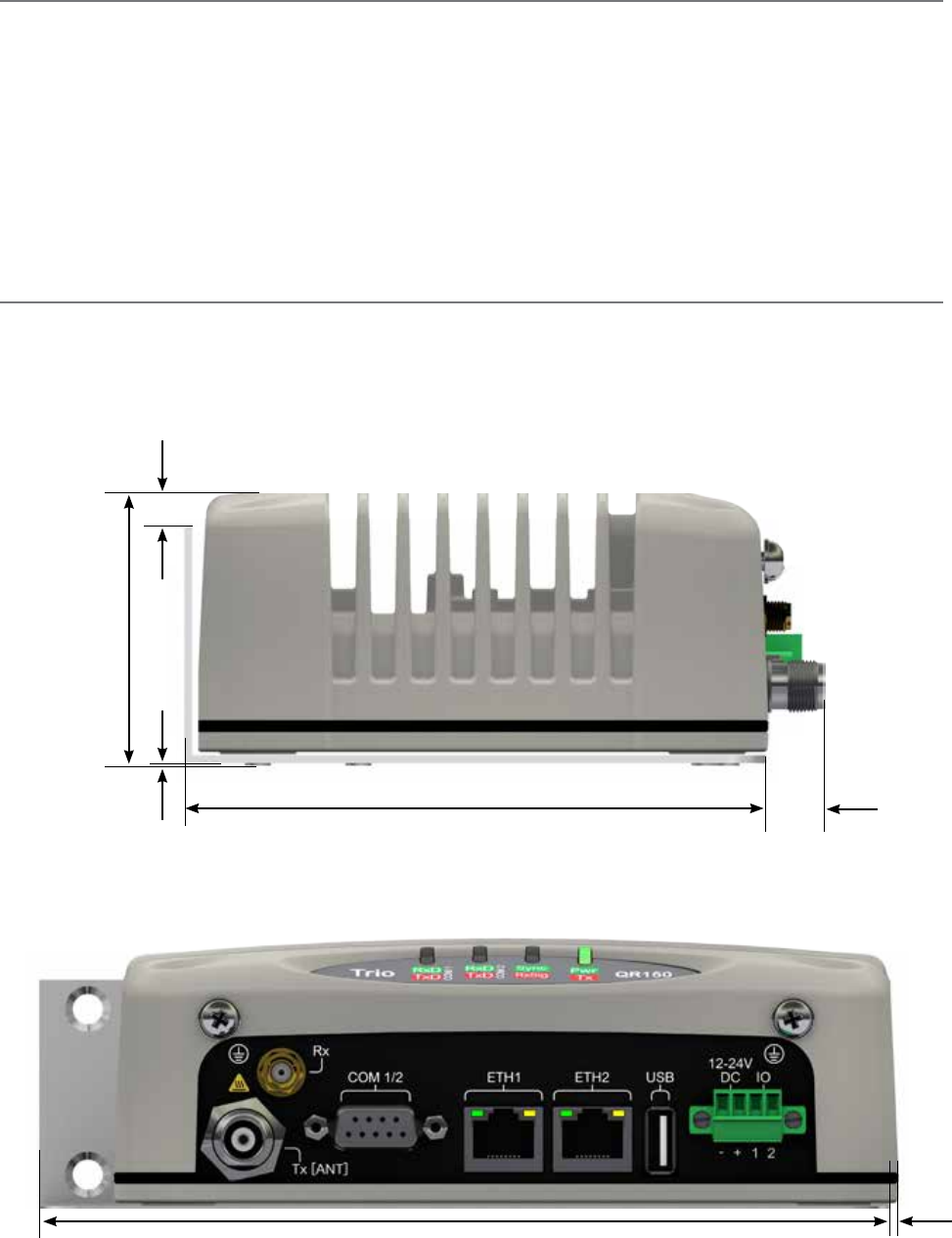
52 Document Number: 0100SM1401 Issue: 12-16
Part F – Quick Reference Guide
DIN rail mounting kit
An optional DIN rail mounting kit is available for the QR150. The mount is screwed onto the bottom of the QR150 giving the
unit the ability to be simply ‘clipped’ and locked onto a 7.5 mm by 35 mm (0.3 in. by 1.4 in.) DIN rail.
Each DIN rail kit supplies:
• x1 DIN rail mounting bracket
• x1 DIN rail clip
• x4 Countersunk M4X8 screws (to mount DIN rail clip to bracket)
• x4 M4 nuts (to mount DIN rail clip to bracket)
• x4 Pan head M3X6 screws (to mount spread-spectrum radio to bracket)
• x4 Pan head M4X2.5 screws (to mount M-Series to bracket)
• x4 Pan head M4X8 screws (to mount QR150/QR450 to bracket)
Drawings not to scale.
118.5mm [4.66in.] (128.5mm [5.05in.] With DIN
clip fitted on rear)
12mm
[0.47in.]
2.5mm
[0.09in.]
60mm [2.36in.]
175mm
[6.89in.]
DIN rail mounting bracket
(70mm [2.75in.] With DIN
clip fitted on bottom)
2.5mm
[0.09in.]
11.5mm
[0.45in.]
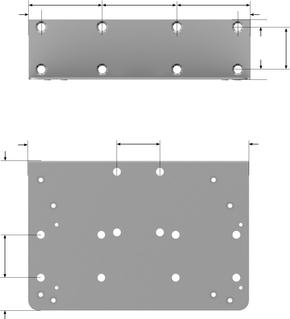
53
Document Number: 0100SM1401 Issue: 12-16
Part F – Quick Reference Guide
26mm
[1.02in.]
34mm
[1.33in.]
34mm [1.34in.]
58.5mm
[2.3in.]
70.5mm [2.77in.]
10mm
[0.39in.]
58mm [2.28in.] 58mm [2.28in.]59mm [2.32in.]
10mm
[0.39in.]
5mm
[0.19in.]
7mm
[0.27in.]
70.5mm [2.77in.]
34mm
[1.33in.]
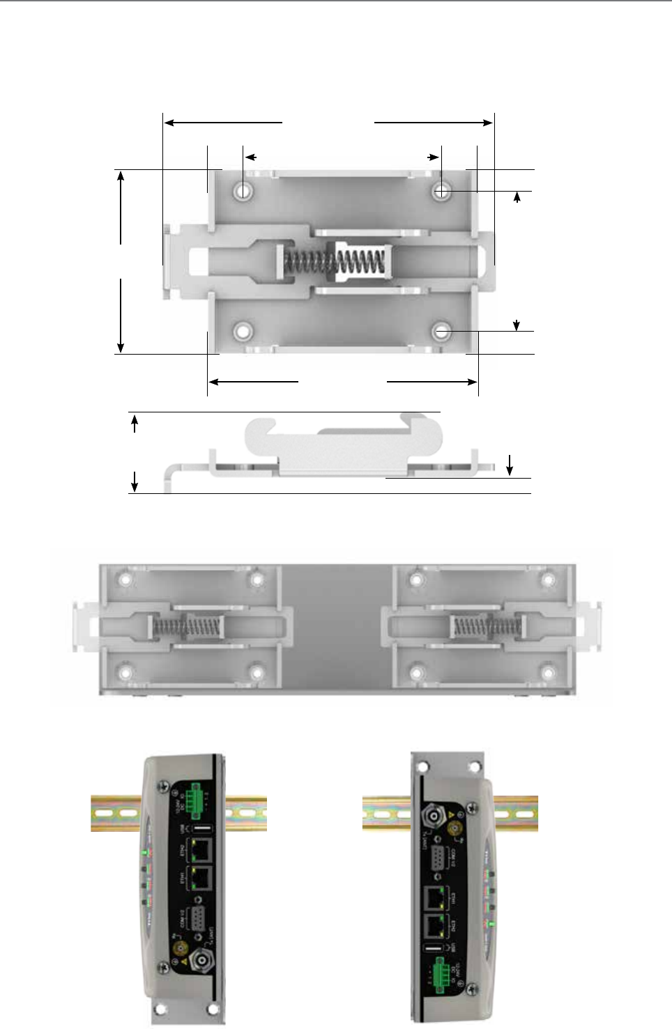
54 Document Number: 0100SM1401 Issue: 12-16
DIN rail clip
The DIN rail clip has a spring loaded latch to allow easy installation/removal of the radio device being installed.
The DIN rail clip can be fitted to the DIN rail mounting bracket x5 different ways to allow as much installation flexibility as
possible.
Rear mount DIN rail clip
The DIN rail clip can be fitted on the rear of the DIN rail mounting bracket two ways shown below.
Examples of rear-fitted DIN clips:
OR
Part F – Quick Reference Guide
65mm [2.55in.]
5mm
[0.19in.]
44mm
[1.73in.]
82mm [3.22in.]
9mm
[0.35in.]
9mm
[0.35in.]
5mm
[0.19in.]
19mm
[0.74in.]
4mm
[0.15in.]
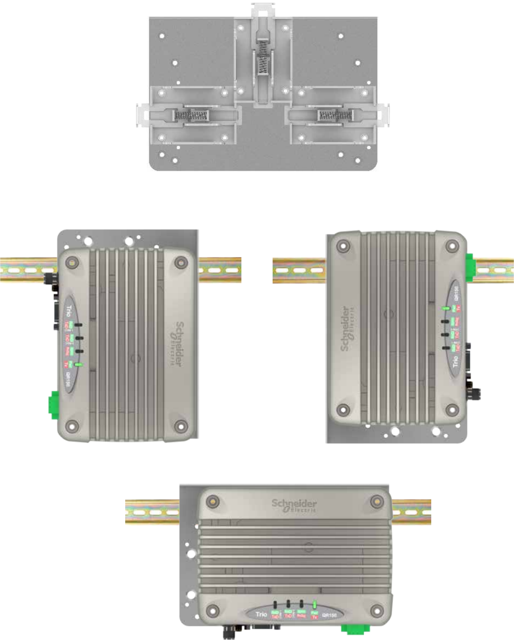
55
Document Number: 0100SM1401 Issue: 12-16
Bottom mount DIN rail clip
The DIN rail clip can be fitted on the bottom of the DIN rail mounting bracket three different ways shown below.
OR
Examples of bottom-fitted DIN clips:
OR
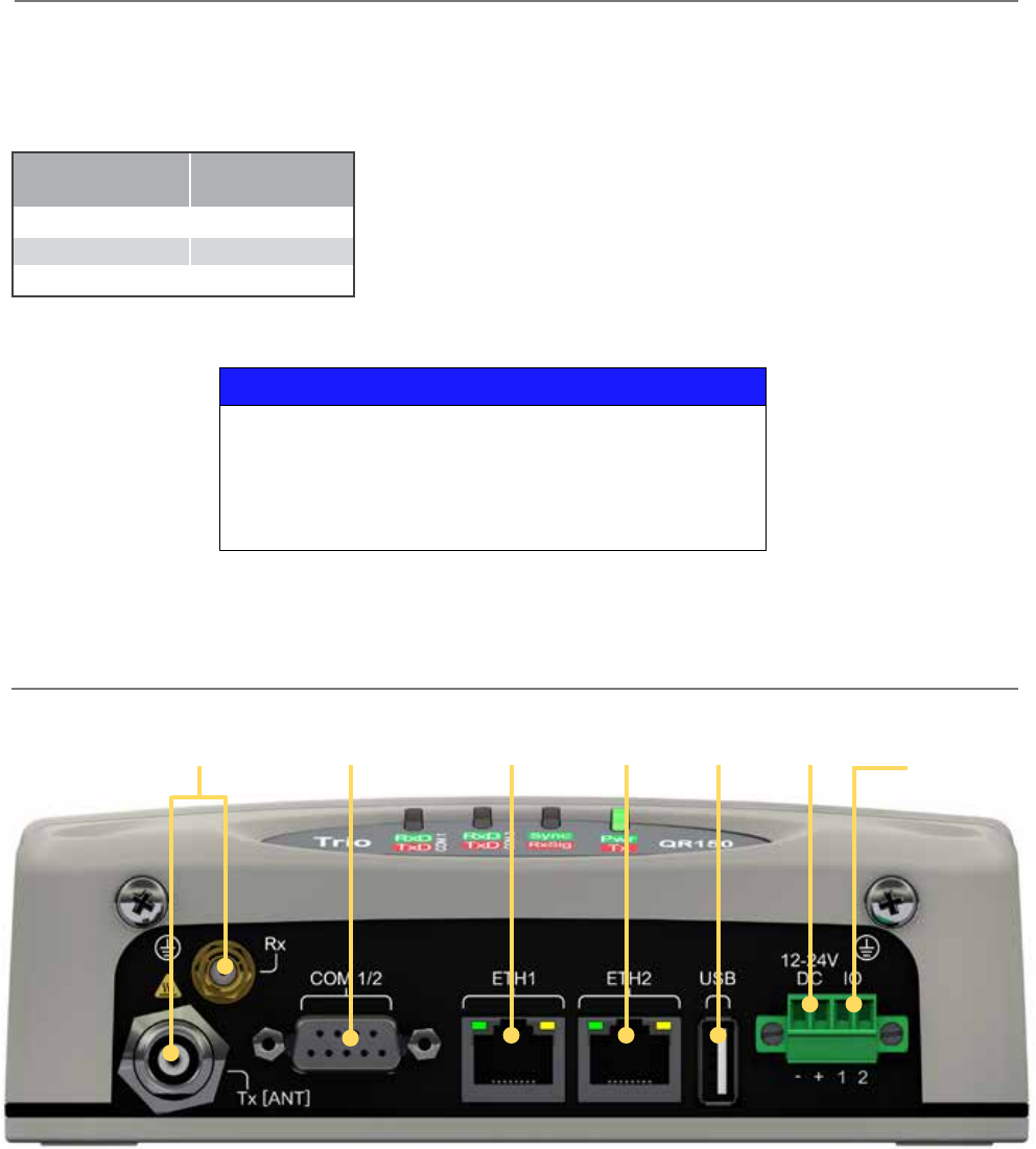
56 Document Number: 0100SM1401 Issue: 12-16
Physical Interfaces
RF Port/s
(TNC/SMA)
Serial Ports -
COM 1 & 2 Ethernet USB port
DC Power
10...30 Vdc
Port 1
Ethernet
port 2
Power Supply Requirements
Rated Operating Voltage: 10...30 Vdc
Nominal Operating Voltage: 12 Vdc and 24 Vdc
Input Power (Rx typical): 5 W
Input Power (Tx typical): (See table below)
Typical receive/standby input power is 5 Watts. The input power will vary in transmit
mode according to RF output power level.
The QR is supplied with a lock-in mating DC power connector (Schneider Electric
Part Number TBUMPWR-PLUG-QR-A) which should be installed with the locking
screws done up tightly (0.5 - 0.6 Nm / 4.42 - 5.31 ftin).
The radio is designed to limit damage if the voltage exceeds 30 Vdc or if reverse
polarity is applied. The field-replaceable internal fuse has a 7 Amp rating. Fuse replacement instructions can be found within this
user manual. Fuses are available from Schnedier Electric, part number TBUMPWR-FUSE-QR.
Tx Power (dBm) Typical Input
Power (Watts)
30 18
37 28
40 39
Connect and secure the antenna, Ethernet and serial connectors BEFORE applying power to the unit. Lastly, before inserting
the power connector, re-check that the polarity and voltage is correct using a multimeter and check the power cable against
the +/- label printed on the front panel of the radio.
NOTICE
HAZARD OF EQUIPMENT DAMAGE
The radio modem can be damaged if there is any potential difference between
the chassis-ground, RS232 signal ground, power (-) input, or antenna coaxial
shield. Before connecting any wiring, ensure that all components are earthed to a
common ground point.
Failure to follow these instructions can result in equipment damage.
Digital I/O
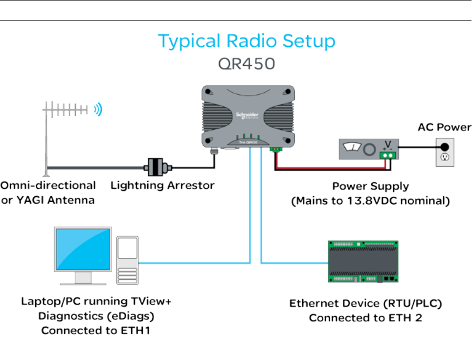
57
Document Number: 0100SM1401 Issue: 12-16
Half Duplex Radio - QR450
Typical Radio Setup
Part F – Quick Reference Guide
Schneider Electric offers a variety of wireless accessories, for further information, refer to the wireless accessories data sheet.
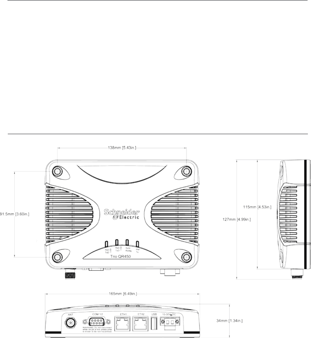
58 Document Number: 0100SM1401 Issue: 12-16
Physical Dimensions
Drawings not to scale.
Part F – Quick Reference Guide
Mounting Instructions
Mount the radio in a clean and dry location, protected from water, excessive dust, corrosive fumes, extremes of temperature
and direct sunlight. In high power or high temperature applications, allow sufficient passive or active ventilation. To avoid
moisture ingress it is suggested to mount the radio with the connectors facing downwards.
When mounting the equipment, consideration should be given to the environmental aspects of the site. The cabinet should
be positioned so that it is shaded from potential high temperature of the afternoon sun, or icy cold wind. Although the radios
are designed for harsh temperature extremes, they will give a longer service life if operated in a more stable temperature
environment.
In an industrial environment, the radio modems should be isolated from excessive vibration, which can destroy electronic
components, joints, and crystals. The cabinet should provide full protection from moisture, dust, corrosive atmospheres, and
residue from ants and small vermin (which can be corrosive or conductive). The radio modem will radiate heat from the in-
built heat sink, and the higher the transmitter duty cycle, the more heat will be radiated from the heat sink. Ensure that there
is sufficient ventilation in the form of passive or forced air circulation to help ensure that the radio is able to maintain quoted
temperature limits.
The QR450 is designed with four mounting holes to allow a flat mount of the radio. Each QR450 comes standard with four
16mm x 40mm self drilling screws. The heads of these screws are low profile wafer heads with a no. 2 Phillips recess.
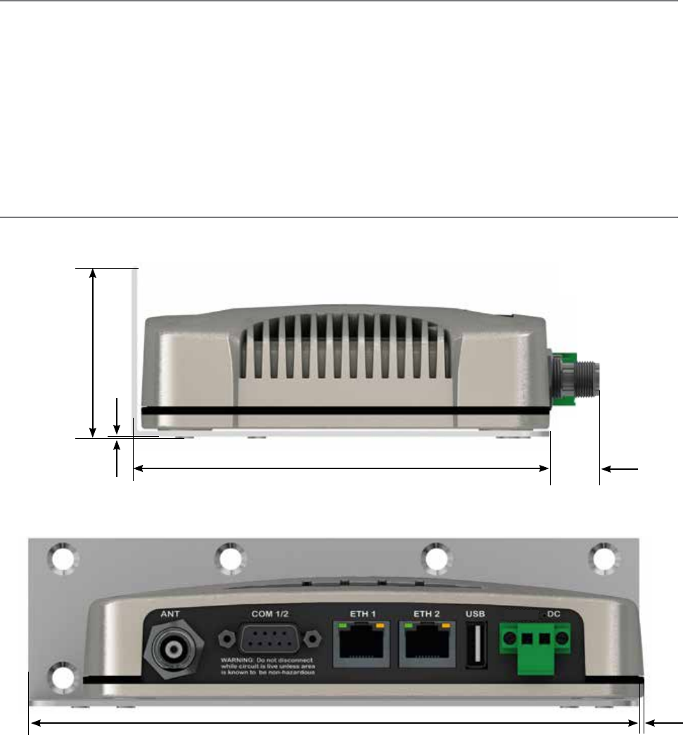
59
Document Number: 0100SM1401 Issue: 12-16
DIN rail mounting kit
An optional DIN rail mounting kit is available for the QR450. The mount is screwed onto the bottom of the QR450 giving the
unit the ability to be simply ‘clipped’ and locked onto a 7.5 mm by 35 mm (0.3 in. by 1.4 in.) DIN rail.
Each DIN rail kit supplies:
• A DIN rail mounting bracket
• A DIN rail clip
• x4 Countersunk M4X8 screws (to mount DIN rail clip to bracket)
• x4 M4 nuts (to mount DIN rail clip to bracket)
• x4 Pan head M3X6 screws (to mount Spread spectrum radio to bracket)
• x4 Pan head M4X2.5 screws (to mount M-Series to bracket)
• x4 Pan head M4X8 screws (to mount QR150/QR450 to bracket)
Drawings not to scale.
118.5mm [4.66in.] (128.5mm [5.05in.] With DIN
clip fitted on rear)
12mm
[0.47in.]
2.5mm
[0.09in.]
48.5mm [1.9in.]
175mm
[6.89in.]
DIN rail mounting bracket
(58.5mm [2.3in.] With
DIN clip fitted on bottom)
Part F – Quick Reference Guide
2.5mm
[0.09in.]
12-24

60 Document Number: 0100SM1401 Issue: 12-16
26mm
[1.02in.]
34mm
[1.33in.]
34mm [1.34in.]
58.5mm
[2.3in.]
70.5mm [2.77in.]
10mm
[0.39in.]
58mm [2.28in.] 58mm [2.28in.]59mm [2.32in.]
10mm
[0.39in.]
5mm
[0.19in.]
7mm
[0.27in.]
70.5mm [2.77in.]
Part F – Quick Reference Guide
34mm
[1.33in.]
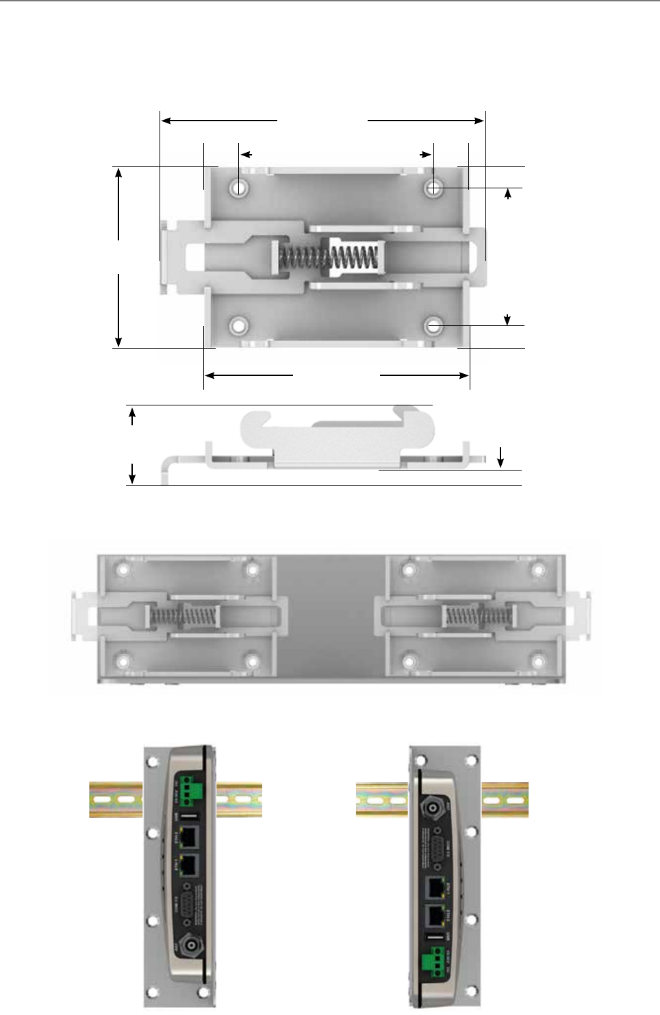
61
Document Number: 0100SM1401 Issue: 12-16
DIN rail clip
The DIN rail clip has a spring loaded latch to allow easy installation/removal of the radio device being installed.
The DIN rail clip can be fitted to the DIN rail mounting bracket x5 different ways to allow as much installation flexibility as
possible.
Rear mount DIN rail clip
The DIN rail clip can be fitted on the rear of the DIN rail mounting bracket two ways shown below.
Examples of rear fitted DIN clips:
OR
Part F – Quick Reference Guide
65mm [2.55in.]
5mm
[0.19in.]
44mm
[1.73in.]
82mm [3.22in.]
9mm
[0.35in.]
9mm
[0.35in.]
5mm
[0.19in.]
19mm
[0.74in.]
4mm
[0.15in.]
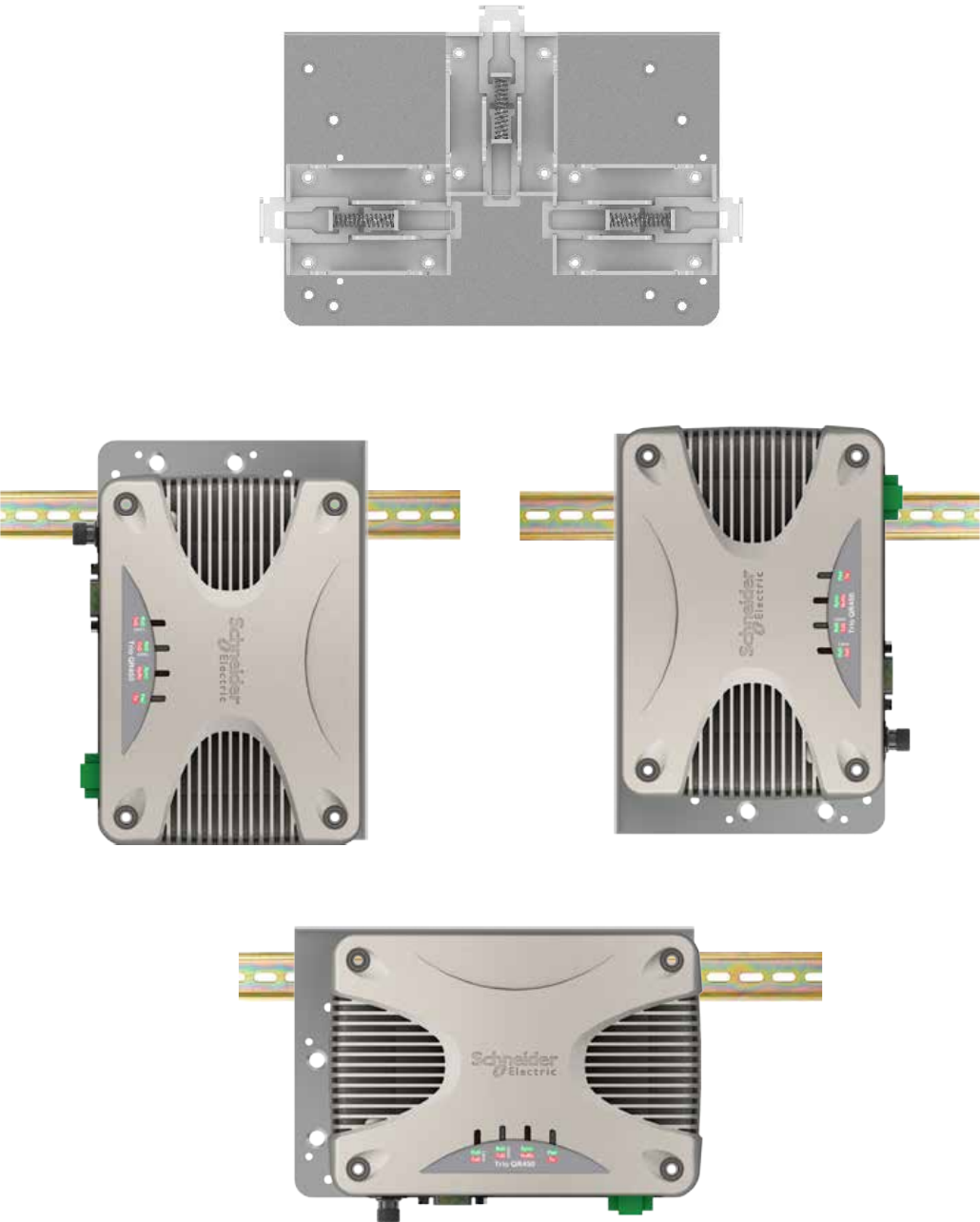
62 Document Number: 0100SM1401 Issue: 12-16
Bottom mount DIN rail clip
The DIN rail clip can be fitted on the bottom of the DIN rail mounting bracket three different ways shown below.
OR
Examples of bottom fitted DIN clips:
OR
Part F – Quick Reference Guide
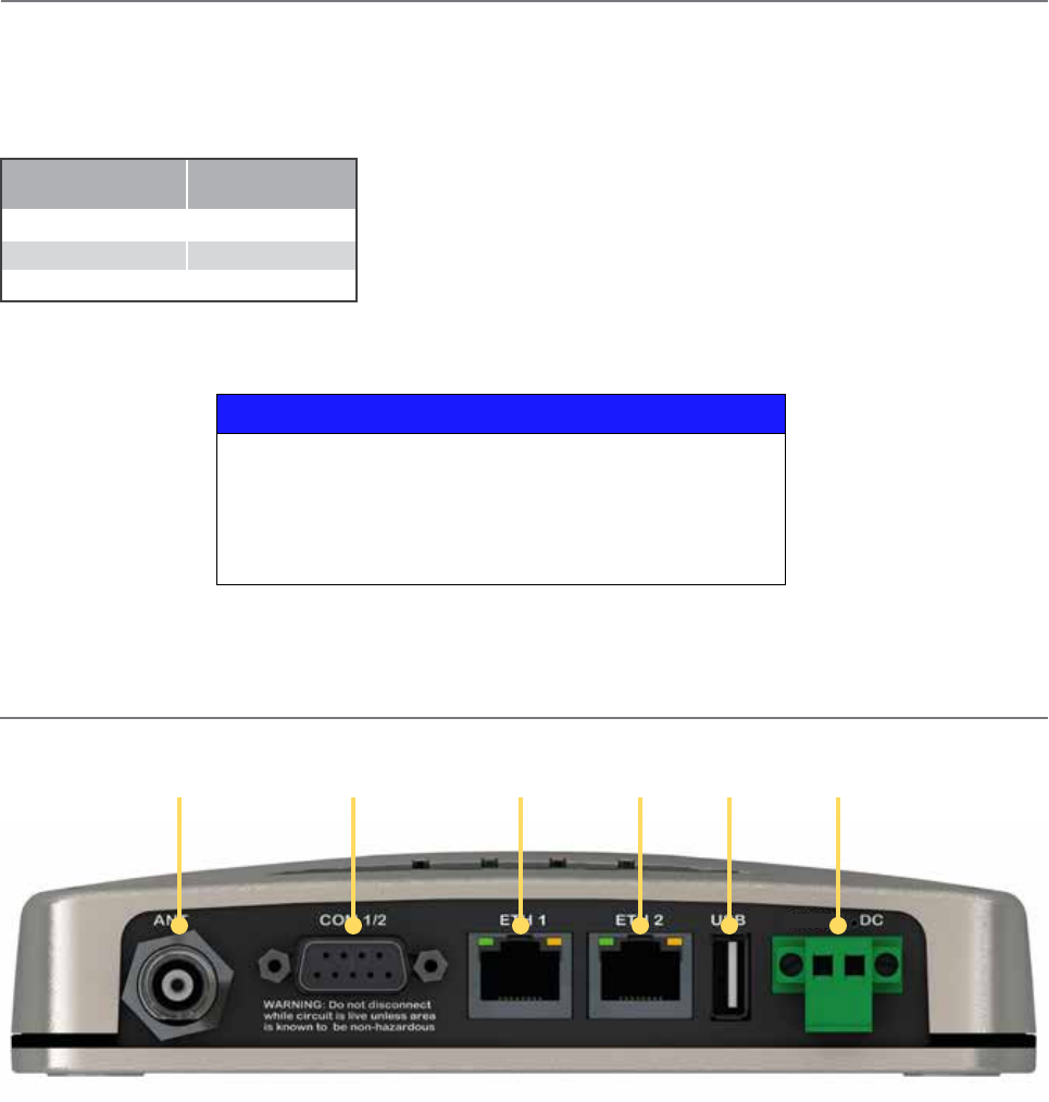
63
Document Number: 0100SM1401 Issue: 12-16
Physical Interfaces
Antenna port
(TNC)
Serial port -
COM 1 & 2 Ethernet USB port
DC input
10 to 30 V
port 1
Ethernet
port 2
Power Supply Requirements
Rated Operating Voltage: 10...30 Vdc
Nominal Operating voltage: 12 and 24 Vdc
Input Power (Rx typical): 5 Watts
Input Power (Tx typical): (See table below)
Typical receive/standby input power is 5 Watts. The input power will vary in transmit
mode according to RF output power level.
The QR450 is supplied with a lock-in mating DC power connector (Schneider
Electric Part Number TBUMPWR-PLUG-QR-A) which should be installed with the
locking screws done up tightly (0.5 - 0.6 Nm / 4.42 - 5.31 ftin).
The radio is designed to limit damage if the voltage exceeds 30 Vdc or if reverse
polarity is applied. The field-replaceable internal fuse has a 7 Amp rating. Fuses are available from Schnedier Electric, part
number TBUMPWR-FUSE-QR. Fuse replacement instructions can be found within this user manual.
Tx Power (dBm) Typical Input
Power (Watts)
30 24
37 37
40 52
Connect and secure the antenna, Ethernet and serial connectors BEFORE applying power to the unit. Lastly, before inserting
the power connector, re-check that the polarity and voltage is correct using a multimeter and check the power cable against
the +/- label printed on the front panel of the radio.
Part F – Quick Reference Guide
NOTICE
HAZARD OF EQUIPMENT DAMAGE
The radio modem can be damaged if there is any potential difference between
the chassis-ground, RS232 signal ground, power (-) input, or antenna coaxial
shield. Before connecting any wiring, ensure that all components are earthed to a
common ground point.
Failure to follow these instructions can result in equipment damage.
12-24
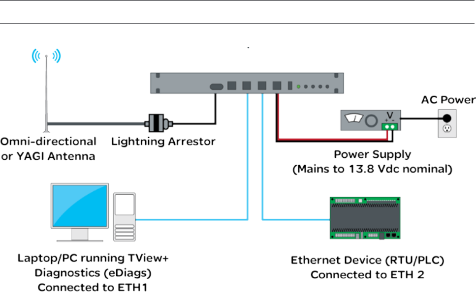
64 Document Number: 0100SM1401 Issue: 12-16
Part F – Quick Reference Guide
Full Duplex Radio - QB
Typical Radio Setup
Schneider Electric offers a variety of wireless accessories, for further information, refer to the wireless accessories data sheet.
QB
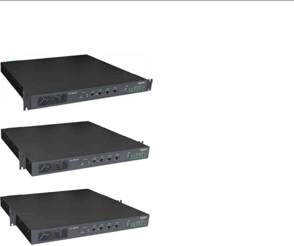
65
Document Number: 0100SM1401 Issue: 12-16
Part F – Quick Reference Guide
Mounting
The QB Full Duplex Radio is housed in a 1RU 19” rack enclosure. The radio is supplied with x2 1RU mounting brackets, which
should be fitted to each side of the radio before it can be installed into a 19” rack. The mounting brackets can be fitted to
the side of the radio in 3 different locations to provide different mounting capabilities: Front Mount, Proud Mount or Center
Mount.
The radio should be mounted in a clean and dry location, protected from water, excessive dust, corrosive fumes, extremes of
temperature and direct sunlight. Allow sufficient passive or active ventilation to allow the radio modem’s heat sink to operate
efficiently.
Antenna connections, Power connections and Digital I/O are all made at the rear of the unit.
All User ports, including; Serial Com ports, Ethernet ports, and Aux port are located on the front panel to provide easy access.
Front Mount
Fixing the mounting brackets for a front mount,
allows the front of the radio to be flush with the
front of a 19” rack.
Proud Mount
Fixing the mounting brackets for a proud
mount, allows the front of the radio to slightly
hang over the front of a 19” rack.
Center Mount
Fixing the mounting brackets for a center
mount, allows the radio to be mounted into a
19” rack which contains a center pillars.
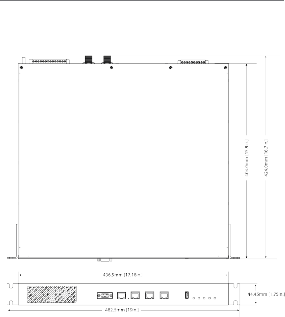
66 Document Number: 0100SM1401 Issue: 12-16
Physical Dimensions
19” (483mm) 1 RU rack mount.
Without mounting brackets, D:424 x H:44.45 x W:436.5mm (D:16.7” x H:1.75” x W:17.18”)
Drawings not to scale.
Part F – Quick Reference Guide

67
Document Number: 0100SM1401 Issue: 12-16
Power Supply Requirements
Operating Voltage: 11...30 Vdc (Dual Input)
Input Power (Rx typical): 14 Watts
Input Power (Tx typical): (See table below)
In high ambient temperature situations, the internal fans may operate, resulting in an increase of input power of up to 28
Watts.
Typical receive/standby input power is 14 Watts. The input power will vary in
transmit mode according to RF output power level.
The QB is supplied with a lock-in mating DC power connector
which should be installed with the locking screws done up tightly
(0.5 - 0.6 Nm / 4.42 - 5.31 ftin ). Replacement parts available from Schneider
Electric, part number TBUMPWR-PLUG-QB.
The radio is designed to limit damage if the voltage exceeds the operating voltage
or if reverse polarity is applied. The field replaceable internal fuse has a 12 Amp rating.
Replacement fuses available from Schneider Electric, part number TBUMPWR-FUSE-QB.
Connect and secure the antenna, Ethernet and serial connectors BEFORE applying power to the unit. Lastly, before inserting the
power connector, re-check that the polarity and voltage is correct using a multimeter and check the power cable against the +/-
label printed on the rear panel of the radio.
Tx Power (dBm)
Typical Input
Power (Watts)
QB150 QB450
30 26 34
37 38 46
40 46 59
Part F – Quick Reference Guide
NOTICE
HAZARD OF EQUIPMENT DAMAGE
The radio modem can be damaged if there is any potential difference between
the chassis-ground, RS232 signal ground, power (-) input, or antenna coaxial
shield. Before connecting any wiring, ensure that all components are earthed to a
common ground point.
Failure to follow these instructions can result in equipment damage.
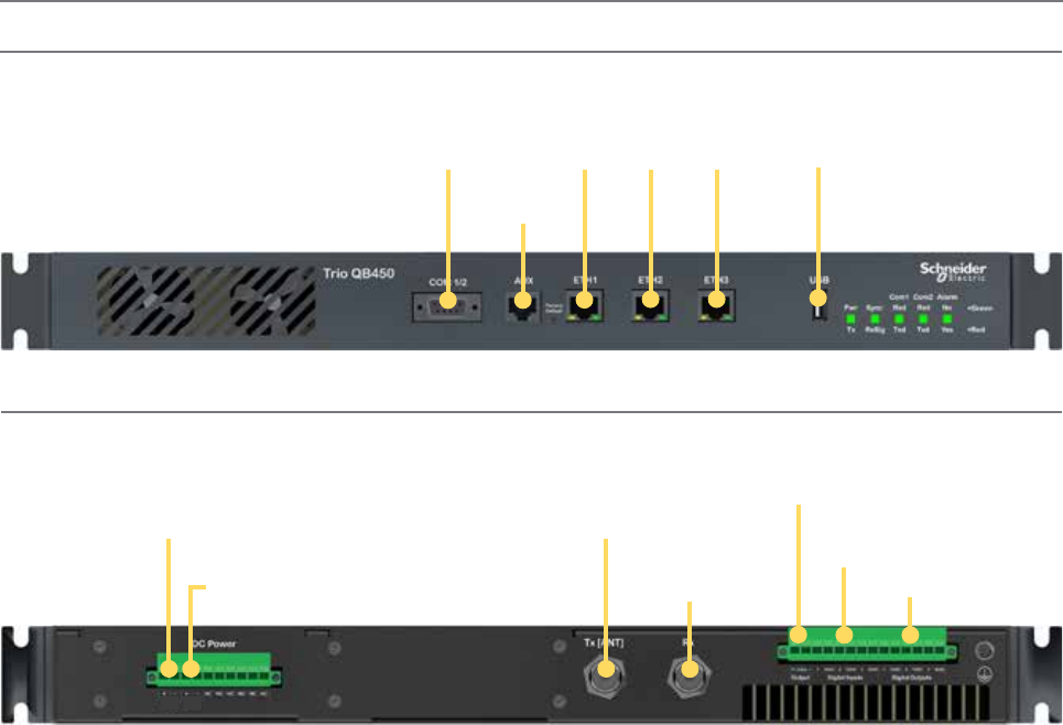
68 Document Number: 0100SM1401 Issue: 12-16
Physical Interfaces
Serial port -
COM 1 & 2 USB port
Auxiliary
port
Ethernet Ports
1 2 3
Tx Antenna
port (N-Type)
Rx Antenna
port (N-Type)
Primary DC input
11 to 30 V
Secondary DC
input 11 to 30 V
12 Vdc output
(for QHHSC only)
Digital inputs
1, 2 & 3
Digital outputs
1, 2 & 3
Front Panel
Rear Panel
Part F – Quick Reference Guide
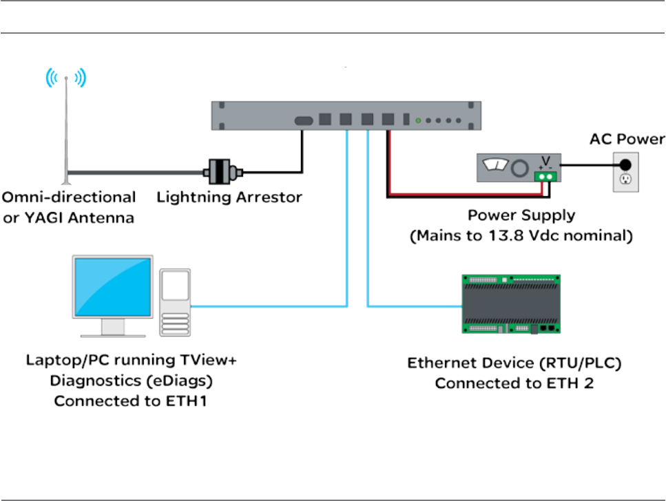
69
Document Number: 0100SM1401 Issue: 12-16
Hot Standby Half Duplex Radio - QP
Typical Radio Setup
Operational Description
The QP hot standby half duplex radio, is a 1RU rack mounted module which operates with two internal highly reliable half
duplex radios, which can be switched between to provide redundancy.
The two half duplex radios (Radio A & Radio B) operate simultaneously and depending on the QP antenna option, there are
different antenna arrangements available:
- Option B: Duplicate Ports - This option provide a separate antenna port for each of the internal radios.
- Option D (QP150 only): Separate Switched Ports - This option provides a separate antenna port for the receiver,
and the transmitter. Ownership of the ports will belong to the online remote, controlled by internal switching.
- Option E: Common Port - This option will connect the internal radio’s antenna ports through an RF relay, providing
a single antenna port on the QP.
Only data received by the “online” radio is directed to the user equipment. The online radio is also the only unit transmitting
at any time. The QP can perform the following functions:
• Monitor the alarm output from both radio A and radio B and change over the online radio if required.
• Switch all user data through to the online radio.
• Switch the antenna via internal coaxial relay to the online radio transmitter (Requires QP Kit Option E).
Digital switching in the QP directs user data to and from the user ports on the front panel directly to the user ports of the online radio.
Part F – Quick Reference Guide
Schneider Electric offers a variety of wireless accessories, for further information, refer to the wireless accessories data sheet.
QP
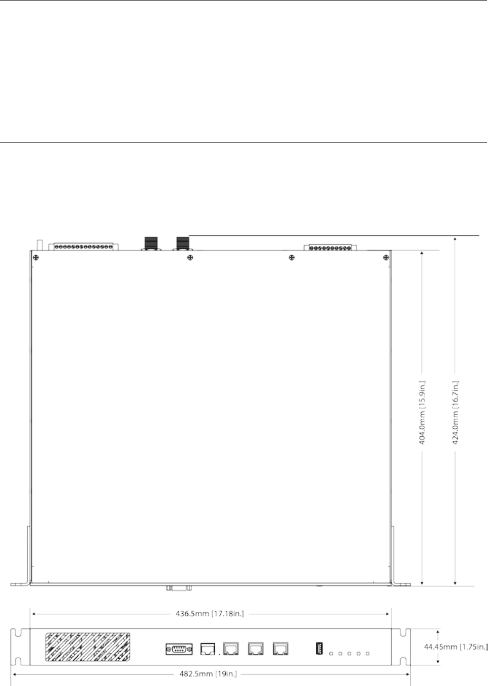
70 Document Number: 0100SM1401 Issue: 12-16
Mounting Guidelines
The QP hot standby half duplex radio is housed as a 1RU 19” rack mounted unit. There are mounting brackets included for
the front panel, which can be used to secure the unit to the rack. The mounting brackets can be fitted to the side of each
unit in 3 different locations to provide different mounting capabilities: Front Mount, Proud Mount or Center Mount. Refer to
the QB Mounting guide for a graphical representation of the different mounting positions.
The unit should be mounted in a clean and dry location, protected from water, excessive dust, corrosive fumes, extremes of
temperature and direct sunlight. Allow sufficient passive or active ventilation to allow the radio fans to pass air through the
internal heat sink efficiently.
All RF, power and digital I/O connections are made at the rear of the unit. All User interfaces are located at the front of the
unit, this includes: Ethernet interface, Serial COM port interfaces and Auxiliary interface.
Physical Dimensions
19” (483mm) 1 RU rack mount.
Without mounting brackets, D:424 x H:44.45 x W:436.5mm (D:16.7” x H:1.75” x W:17.18”)
Part F – Quick Reference Guide
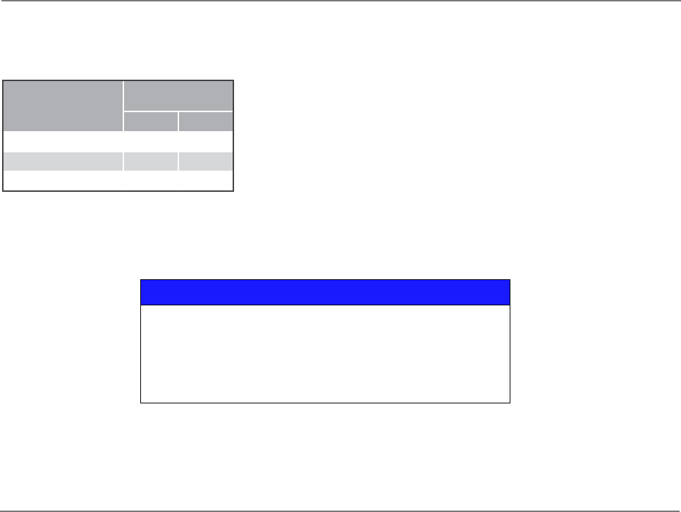
71
Document Number: 0100SM1401 Issue: 12-16
Power Supply Requirements
Operating Voltage: 11...30 Vdc (Dual Input)
Input Power (Rx typical): 14 Watts
Input Power (Tx typical): (See table below)
In high ambient temperature situations, the internal fans may operate, resulting
in an increase of input power of up to 28 Watts.
Typical receive/standby input power is 14 Watts. The input power will vary in
transmit mode according to RF output power level.
The QP is supplied with a lock-in mating DC power connector which should be
installed with the locking screws done up tightly (0.5 - 0.6 Nm / 4.42 - 5.31 ftin).
Replacement parts available from Schneider Electric, part number TBUMPWR-PLUG-QB.
The radio is designed to limit damage if the voltage exceeds the operating voltage or if reverse polarity is applied.
The field-replaceable internal fuse has a 12 Amp rating. Replacement fuses available from Schneider Electric, part number
TBUMPWR-FUSE-QB.
Connect and secure the Antenna, Ethernet and Serial connectors BEFORE applying power to the unit. Lastly, before inserting the
power connector, re-check that the polarity and voltage is correct using a multimeter and check the power cable against the +/-
label printed on the rear panel of the radio.
NOTICE
HAZARD OF EQUIPMENT DAMAGE
The radio modem can be damaged if there is any potential difference between
the chassis-ground, RS232 signal ground, power (-) input, or antenna coaxial
shield. Before connecting any wiring, ensure that all components are earthed to a
common ground point.
Failure to follow these instructions can result in equipment damage.
Part F – Quick Reference Guide
IP Allocation
The internal half duplex radios have unique factory default IP addresses:
- Default IP Radio A: 192.168.2.15
- Default IP Radio B: 192.168.2.16
When configuring the QP, ensure that Radio A and Radio B have unique IP addresses to avoid IP conflicts.
Tx Power (dBm)
Typical Input
Power (Watts)
QP150 QP450
30 26 34
37 38 46
40 46 59
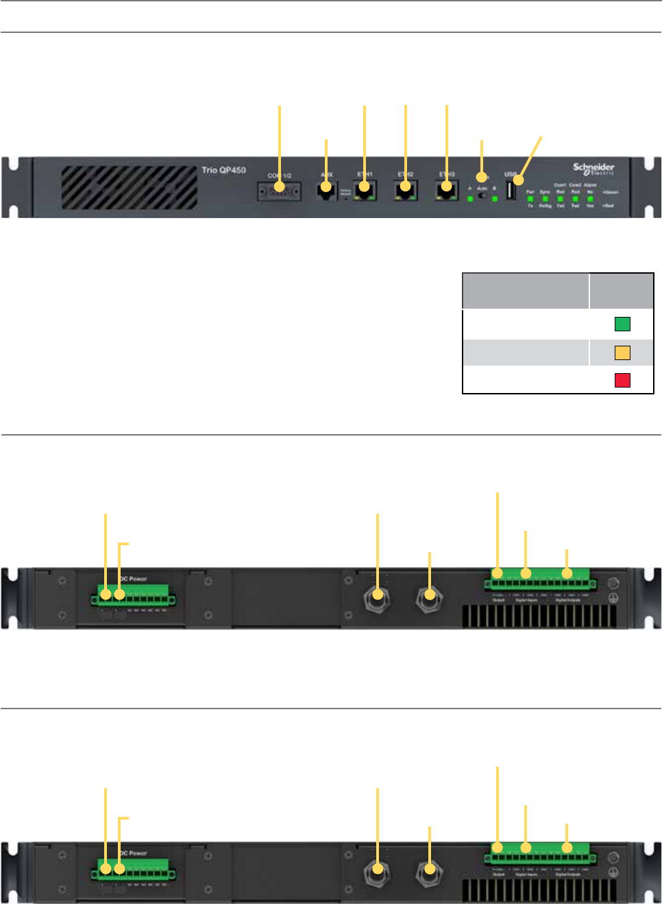
72 Document Number: 0100SM1401 Issue: 12-16
Physical Interfaces
Serial port -
COM 1 & 2
USB port
Auxiliary
port
Ethernet Ports
1 2 3
Radio A (Tx/Rx)
(N-Type)
Radio B (Tx/Rx)
(N-Type)
Primary DC input
11...30 Vdc
Secondary DC
input 11...30 Vdc
12 Vdc output
Digital inputs
1, 2 & 3
Digital outputs
1, 2 & 3
Front Panel
Rear Panel (Hot Standby Option B)
Radio Select
Switch
Radio A
(Tx/Rx)
Radio B
(Tx/Rx)
Rear Panel (Hot Standby Option D) - QP150 Only
Duplicated Antenna Ports
Radio Select Switch
The 3 position switch (A / Auto / B) on the front panel provides the following
functionality:
• Position A: Radio A is forced online
• Position Auto: changeover hardware will select the online radio
• Position B: Radio B is forced online
Adjacent to the select switch are two LEDs: These LEDs indicate the current online radio.
Indicated State Select
LEDs
Auto Mode
Local Force
Remote Force
Part F – Quick Reference Guide
Radio A/B Switched
(Tx only) (N-Type)
Radio A/B Switched
(Rx only) (N-Type)
Primary DC input
11...30 Vdc
Secondary DC
input 11...30 Vdc
12 Vdc output
Digital inputs
1, 2 & 3
Digital outputs
1, 2 & 3
Radio A
(Tx/Rx)
Radio B
(Tx/Rx)
Separate Switched Tx & Rx Ports
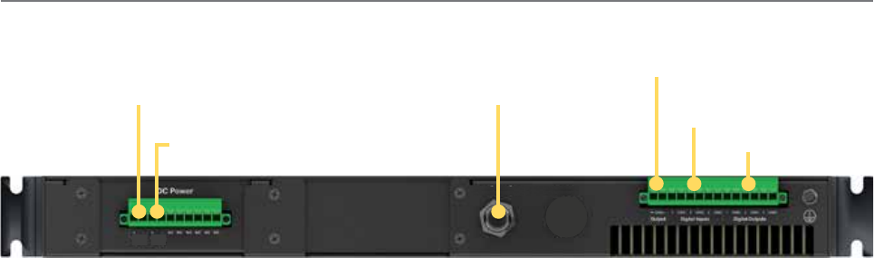
73
Document Number: 0100SM1401 Issue: 12-16
Part F – Quick Reference Guide
Radio A/B Switched
(Tx/Rx) (N-Type)
Primary DC input
11...30 Vdc
Secondary DC
input 11...30 Vdc
12 Vdc output
Digital inputs
1, 2 & 3
Digital outputs
1, 2 & 3
Rear Panel (Hot Standby Option E)
Antenna
Common Switched Antenna Ports
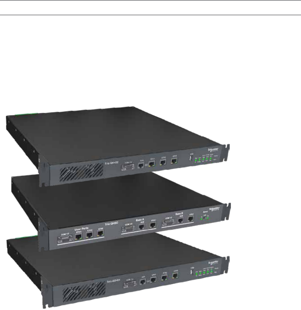
74 Document Number: 0100SM1401 Issue: 12-16
Hot Standby Full Duplex Radio - QH
Introduction
Welcome to the Quick Start Guide for the QH Hot Standby full duplex radio. This section provides additional installation
considerations, wiring diagrams and operational descriptions. This document should be read in conjunction with the QB full
duplex radio Quick Start Guide.
The QH is a redundant, hot standby, full duplex radio providing automatic changeover facilities.
The QH is designed as a modular solution, comprising 2 identical QB full duplex radios (standard) linked to a central monitoring
and changeover controller (Hot Standby Controller). Either QB may be taken out for maintenance without the need for system
down time. The automatic changeover can be triggered by the online out-of-tolerance (alarm) conditions based on either RF
and/or user data throughput parameters.
QB - Full Duplex Radio
QHHSC - Hot Standby
Controller
QB - Full Duplex Radio
Part F – Quick Reference Guide
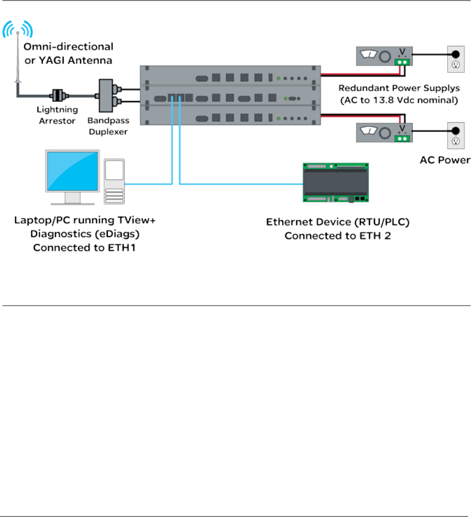
75
Document Number: 0100SM1401 Issue: 12-16
Typical Radio Setup
Operational Description
The QH Hot Standby Controller (QHHSC) unit is a 1RU rack-mounted module that interfaces to two independent full duplex
radios (each 1 RU rack mounted modules) via a number of RF and data cables.
Both full duplex radios (Radio A & Radio B) operate simultaneously, constantly receiving radio signals. However only data from
one radio (the “online” radio) is directed to the user equipment. The online radio is also the only unit transmitting at any time.
The Hot Standby Controller provides the following functions:
• Amplify and split the incoming signal so both Radio A and Radio B receive simultaneously.
• Monitor the alarm output from both Radio A and Radio B and change over the online radio if required.
• Switch all user data through to the online radio.
• Switch the antenna, via internal coaxial relay, to the online radio transmitter (Requires QHHSC Kit Option A).
Digital switching in the QHHSC directs data to and from the user ports on the front panel directly to the user ports of the
online radio.
The QHHSC and the two full duplex radios pass operational/alarm detection status between one another via the AUX
interface. Any alarm detection indicated from the online radio can cause the QHHSC to change over the online radio.
Part F – Quick Reference Guide
Schneider Electric offers a variety of wireless accessories, for further information, refer to the wireless accessories data sheet.
QH
Mounting
The QH hot standby full duplex radio is housed as a 3 RU 19 in. rack mounted set, encompassing two x 1 RU QB full duplex
radios and one x 1 RU QH Hot Standby Controller. The Controller and full duplex radios are each supplied with two x 1 RU
mounting brackets, are to be fitted to each sides of each unit before it can be installed into a 19 in. rack. The mounting
brackets can be fitted to the side of each unit in 3 different locations to provide different mounting capabilities: Front Mount,
Proud Mount or Center Mount. Refer to the QB Mounting guide for a graphical representation of the different mounting
positions.
The unit should be mounted in a clean and dry location, protected from water, excessive dust, corrosive fumes, extremes of
temperature and direct sunlight. Provide sufficient passive or active ventilation to allow the full duplex radio fans to pass air
through the internal heat sink efficiently.
All RF, power and digital I/O connections are made at the rear of the unit. All user interfaces are located at the front of the
unit, these include: Ethernet interface, Serial COM port interfaces and Auxiliary interfaces.
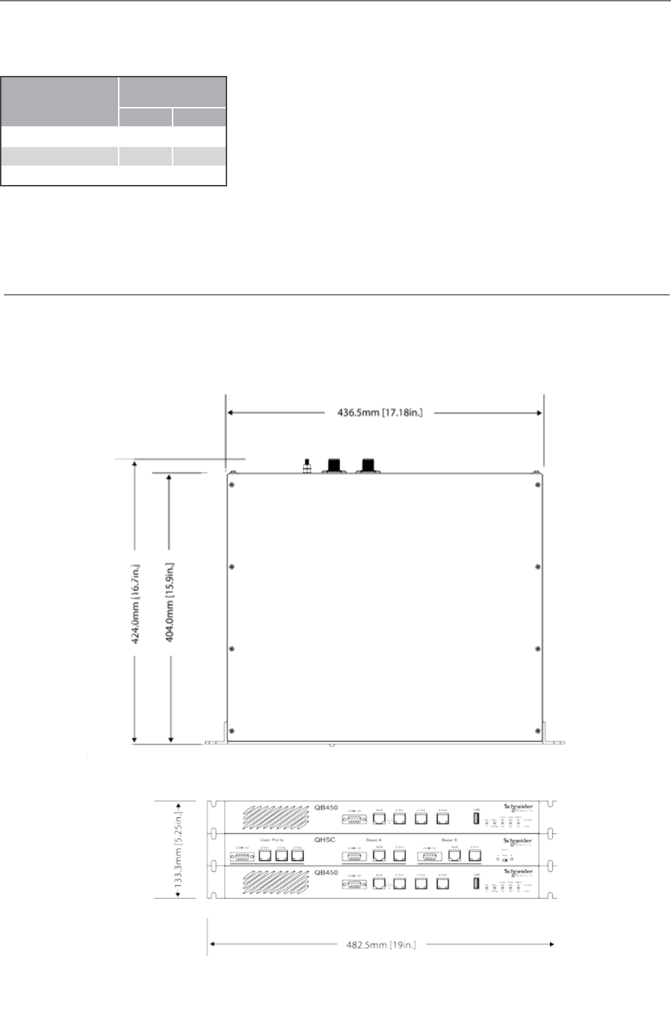
76 Document Number: 0100SM1401 Issue: 12-16
Physical Dimensions
Hot Standby is configured using 2 x QB full duplex radios + 1 x Hot Standby Controller (19 in. 1 RU each) for a total of 19 in.
(483 mm) 3 RU rack mount.
Without mounting brackets, D:424 x H:133.3 x W:436.5 mm (D:16.7 x H:5.25 x W:17.18 in.)
Part F – Quick Reference Guide
Power Supply Requirements
Operating Voltage: 11...30 Vdc (Dual Input)
Input Power (Rx typical): 35 Watts
Input Power (Tx typical): (See table below)
In high ambient temperature situations, the internal fans may operate, resulting in
an increase of input power of up to 56 Watts [x2 QBs].
Typical receive/standby input power is 35 Watts. The input power will vary in transmit
mode according to RF output power level.
Each QB within the hot standby arrangement is supplied with a lock-in mating DC
power connector which should be installed with the locking screws done up tightly
(0.5 - 0.6 Nm / 4.42 - 5.31 ftin ). Replacement parts available from Schneider
Electric, part number TBUMPWR-PLUG-QB.
The radios are designed to limit damage if the voltage exceeds the operating voltage or if reverse polarity is applied. Each QB has a
field-replaceable internal fuse with a 12 Amp rating. Replacement fuses available from Schneider Electric, part number
TBUMPWR-FUSE-QB.
Tx Power (dBm)
Typical Input
Power (Watts)
QH150 QH450
30 48 55
37 59 67
40 68 80
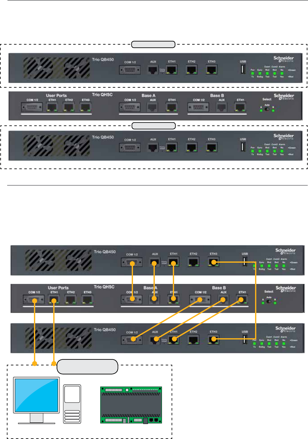
77
Document Number: 0100SM1401 Issue: 12-16
Radio Position Allocation
The QH is made up of three separate devices, a single QH hot standby controller and two separate QB full duplex radios.
Within a hot standby arrangement, the two full duplex radios must be allocated a QH position, either Radio A or Radio B.
The diagrams on the following pages use the radio position allocation shown below.
Radio A
Radio B
Communication Ports
There are multiple connections required between the front panel interfaces of the QH
• COM 1/2 (Both Radios to QHHSC)
• AUX (Both Radios to QHHSC)
• ETH 1 (Both Radios to QHHSC)
• ETH 3 (Between Radios A & B)
SCADA Host / SCADA
Equipment
Part F – Quick Reference Guide
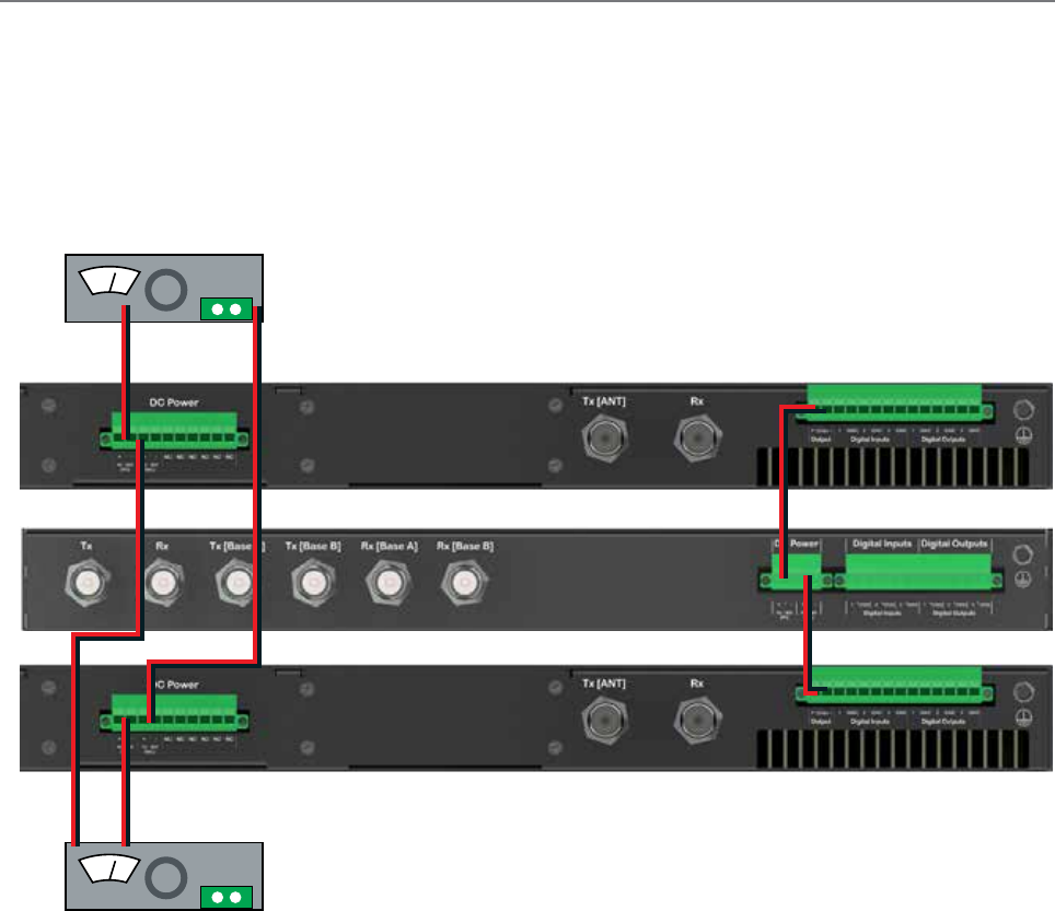
78 Document Number: 0100SM1401 Issue: 12-16
Power Supply and Protection
In order to provide power to this redundant, hot standby radio system, the QH supports dual power supplies. A separate power
supply is used for each of the full duplex radios. To help increase reliability, the power supplies are crossed-over to each of the
secondary supply inputs of the full duplex radios as shown in the diagram below.
Each full duplex radio has diode-ORed supply inputs, making a redundant power supply pair for each full duplex radio possible.
The Hot Standby Controller has connections for dual power supplies and is powered from the 12V DC output of the full duplex
radios as shown in the diagram below.
Part F – Quick Reference Guide
V
+ -
V
+ -
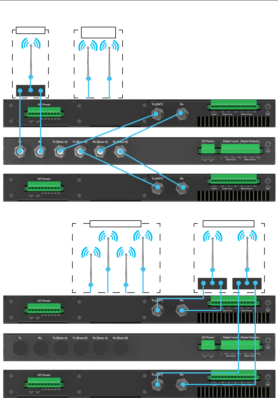
79
Document Number: 0100SM1401 Issue: 12-16
Antennas and RF Feeders
There are two primary antenna connection options. All connectors are standard N-Type sockets. See diagrams below.
Hot Standby Controller Kit: Option A
Hot Standby Controller Kit:
Option A OR B
Part F – Quick Reference Guide
OR
Via separate duplexersIndependent antennas
Via duplexer Separate Rx/Tx
Antennas
OR
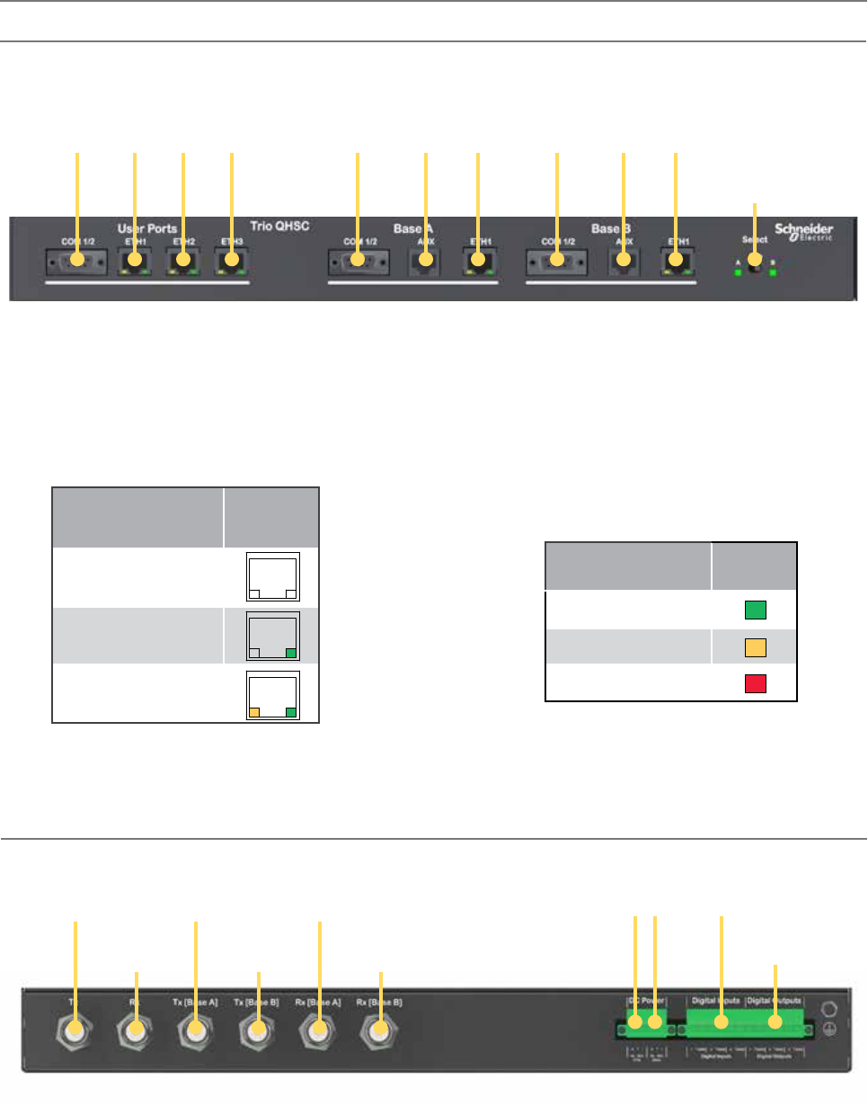
80 Document Number: 0100SM1401 Issue: 12-16
Select Switch
The 3 position switch (A / Auto / B) on the front panel
provides the following functionality:
• Position A: Radio A is forced online
• Position Auto: changeover hardware will select
the online radio
• Position B: Radio B is forced online
Adjacent to the Select switch are two LEDs. These LEDs
indicate the current online radio.
Indicated State ETH port
Ethernet port inactive, no
cable connected
Ethernet port active @
10Mbps
Ethernet port active @
100Mbps
User Ports
Digital switching in the hot standby controller directs
user data to and from the user ports on the front panel
directly to the user ports on the online radio.
Ethernet Port LED Indicators
Indicated State Select
LEDs
Auto Mode
Local Force
Remote Force
Part F – Quick Reference Guide
Physical Interfaces
Front Panel
Rear Panel (Hot Standby Controller Option A)
User Ports Radio B
Radio A
Ethernet Ports
1 2 3 Serial port
COM 1 & 2
Ethernet
Port
Aux
Port
Serial port
COM 1 & 2
Ethernet
Port
Aux
Port
Serial port
COM 1 & 2
Radio Select
Switch
Dual 12V
DC Inputs
Tx Antenna
port (N-Type)
Rx Antenna
port (N-Type)
Digital inputs
1, 2 & 3
Digital outputs
1, 2 & 3
Radio A Tx Radio A Rx
Radio B Tx Radio B Rx
Hot Standby Controller Option B
The QHHSC Option B connections are identical to option A however, option B does not include any RF interfaces on the HSC.
Pairing Alarm
Each QB within a Hot standby arrangement, should have HSC
Mode enabled by the user. If HSC Mode is disabled in both
QBs, the HSC will indicate a pairing alarm by illuminating the A
& B LEDs RED.
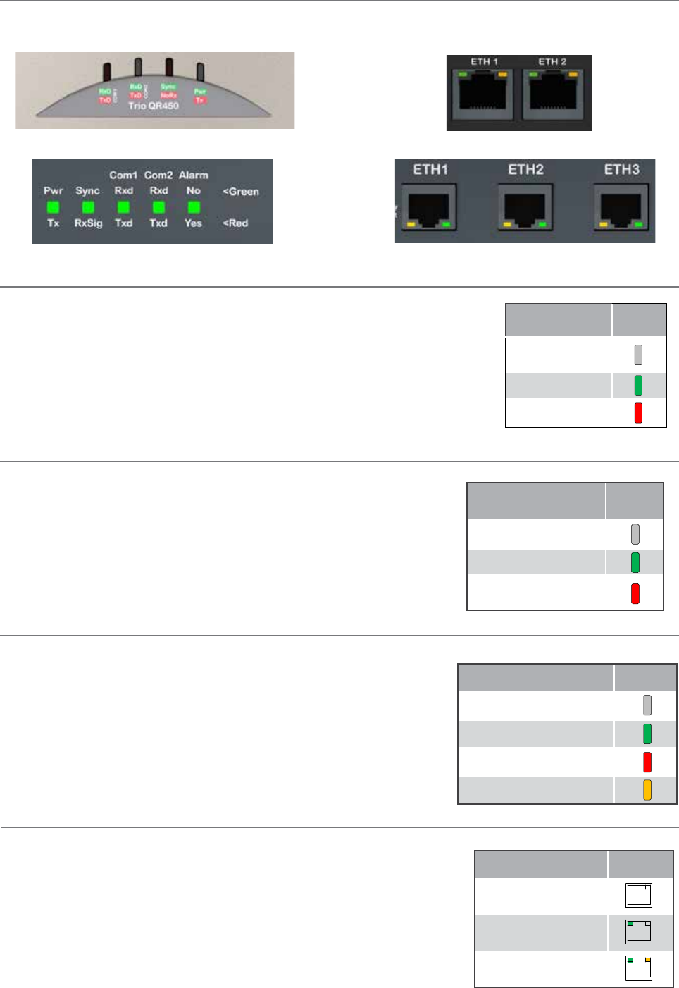
81
Document Number: 0100SM1401 Issue: 12-16
LED indicators
Part F – Quick Reference Guide
Indicated State Pwr/Tx
No power, or
ShutDown
Power on
Transmitter On
Each image below shows where to find the LED indicators of each Q data radio.
Top of QR Front of QR
Front of QB & QP Front of QB, QP & QHHSC
Pwr/TX - DC Power & TX LEDs
If all the LEDs are off, no DC power is reaching the radio modem or the internal fuse is open.
Successful power-up is indicated by the Pwr/Tx LED showing a continuous GREEN state.
Tx Indicator (Tx) : When the transmitter is active the Pwr/Tx LED is in a RED state.
The QR will take approximately 60 seconds to boot up - during this time, the DC power
LED will flash green/off periodically along with various LED activity. Wait until the DC power
LED is not longer periodically flashing and is in a solid green state before attempting to
communicate with the radio.
Indicated State Synch/
RxSig
No received signal
Receiver in SYNC state
RSSI over mute level
and no sync
Indicated State COM1/2
No Activity
RxD Data Output
TxD Data Input
RxD & TxD Data Active
Sync/No RX - Synchronisation and No Received Signal LEDs
A flashing or solid green Sync/No RX LED indicates that the modem is receiving
decodable transmissions from another source.
A regular/solid flashing red Sync/No RX LED indicates that the modem is receiving
un-decodable transmissions from another source. This symptom can be caused by
insufficient RX signal, too much interference or an incorrect configuration parameter
set within the pair of modems.
TxD/RxD (COM 1 and COM 2) - Serial TxD/RxD LEDs
The RxD/TxD LEDs indicate data flow into/out of the serial user port. Data being
sent to the port for transmission is indicated by a red flash, and data being received
over the air and then forwarded to the serial port is shown as a green flash. As
the serial port is full duplex, there may be instances where the TxD and RxD LEDs
illuminate simultaneously, this will be indicated by an amber illumination of the port
LED.
Indicated State ETH port
Ethernet port inactive,
no cable connected
Ethernet port active @
10Mbps
Ethernet port active @
100Mbps
ETH 1 & ETH 2 - Ethernet Link and Activity LEDs
The Ethernet port LEDs are found on the physical RJ45 sockets, located on the
front panel. Green LED activity typically represents a current physical connection to
another Ethernet device has been established. Amber LED activity indicates Ethernet
data is being transferred between the local Ethernet port and another Ethernet
device.
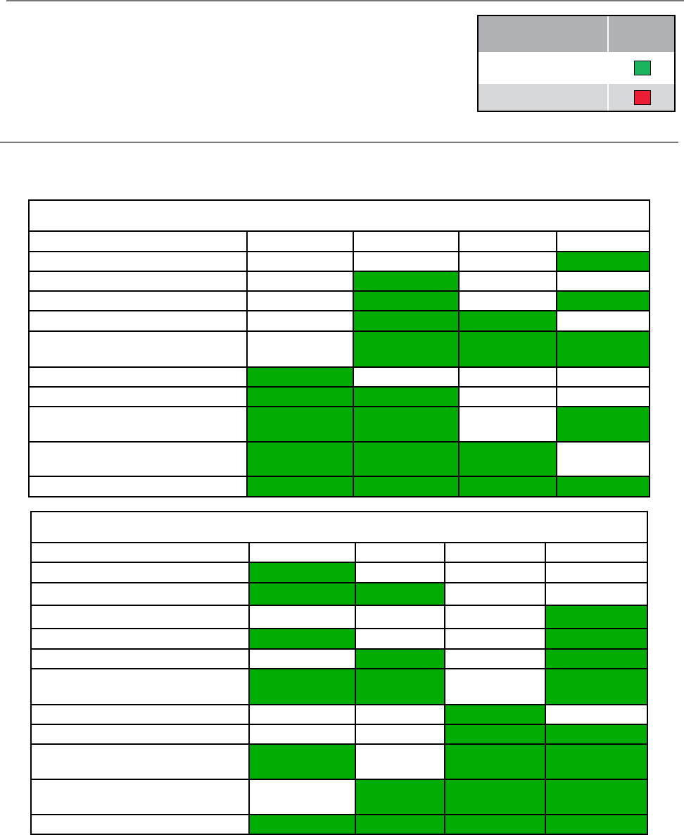
82 Document Number: 0100SM1401 Issue: 12-16
Indicated State Alarm
No active alarm
Alarm/s detected
Alarm detection indicator LED (QB & QP only)
The Alarm LED state has two states:
Green: No alarms are currently detected.
Red: An alarm or alarms are currently active. This can be a critical alarm or an
enabled user alarm. See alarms section for further details.
Alarm LED Indications
In some circumstances the radio will indicate an alarm state. This is shown as all LEDs flashing RED for 1 sec and then a pattern of
green LEDs for 1 sec. The pattern of green LEDs indicate the type of alarm. Consult the table for more information.
QR Half Duplex Remote
Alarm Type COM 1 RxD / TxD COM 2 RxD / TxD Sync / NoRx Pwr / Tx
Supply voltage alarm Green
Retry Factory default Green
Configuration alarm Green Green
Firmware upgrade alarm Green Green
Reverted to factory default due to
internal alarm
Green Green Green
IP address not set (DHCP) Green
Configuration record not found Green Green
Over temperature alarm
(Tx has been disabled)
Green Green Green
Over temperature alarm
(Tx has been folded back)
Green Green Green
VSWR alarm Green Green Green Green
QB / QP
Alarm Type Pwr / Tx Sync / NoRx COM 1 RxD / TxD COM 2 RxD / TxD
Supply voltage alarm Green
Pairing Alarm (Hot Standby Mode) Green Green
Retry Factory default Green
Configuration alarm Green Green
Firmware upgrade alarm Green Green
Reverted to factory default due to
internal alarm
Green Green Green
IP address not set Green
Configuration record not found Green Green
Over temperature alarm
(Tx has been disabled)
Green Green Green
Over temperature alarm
(Tx folded back)
Green Green Green
VSWR alarm Green Green Green Green
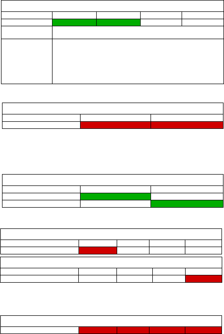
83
Document Number: 0100SM1401 Issue: 12-16
Part F – Quick Reference Guide
QR / QB / QP
Operation Alarm Red Red Red Red
Operational Alarm
An operational alarm is indicated by all 4 LEDs periodically flashing red (no green flashes). This alarm can indicate the radio has
detected an error which may not be recoverable by the user. Depending on why the operational alarm has occurred, the event log
can be referred to, which may help diagnose why operation alarm is active.
HSC Mode Alarm
Each QB within a Hot Standby arrangement should have HSC Mode enabled by the user. When HSC mode is enabled, the QB
will attempt to negotiate and pair with an alternate QB. If HSC mode is disabled, a QB will ignore any HSC mode negotiation
messages it receives.
QB (within a QH)
Alarm Type Pwr / Tx Sync / NoRx COM 1 RxD / TxD COM 2 RxD / TxD
Pairing Alarm Green Green
Description of Alarm When a QB in HSC mode attempts to negotiate with the alternate base, and no response
is received, a pairing alarm will be displayed (flashing all red, then, green as shown above)
Probable Causes (1) There is a mismatch in the configuration between Base A and Base B. Check that
HSC mode, IP address, SUBNET mask, shared IP and VLAN parameters are suitably
configured. For further information on configuration of Hot Standby radios refer to
Part G of this user manual.
(2) There is a problem with the cable connection in the hot standby arrangement.
Check cables are properly inserted into their correct locations.
Refer to “Step 2 - Interface Connections” in the ‘QH Quick Start Guide’ section.
QHHSC
Alarm Type Radio A Radio B
No Base Detected Alarm Red Red
The QHHSC (hot standby controller) indicates an alarm when no QBs are connected (the connection is detected via the Auxiliary
interface). While this alarm is active, the QHHSC front panel becomes inactive.
QB / QP
Alarm Type Pwr / Tx Sync / NoRx COM 1 RxD / TxD COM 2 RxD / TxD
PTT Timeout Alarm Red
PTT Timeout Alarm
When the PTT timeout limit is reached (default is 60 Seconds) the following RED LED will begin to flash on its own.
QR
Alarm Type COM 1 RxD / TxD COM 2 RxD/ TxD Sync / NoRx Pwr / Tx
PTT Timeout Alarm Red
QHHSC Change-Over Pending Timer Alarm
After a change-over occurs within a hot standby arrangement, the QHHSC will run a 60 second timer. If a new alarm is detected
on the online QB during this 60 seconds, the QHHSC will prevent the change-over and indicate a ‘Pending Timer’ alarm. Once
the timer reaches 0, the change-over will proceed. The pending timer helps prevent a high number of change-overs occurring in
a short period of time.
A pending timer alarm is indicated on the QHHSC with a flashing green LED on the corresponding radio LED (Radio A/B).
QHHSC
Alarm Type Radio A Radio B
Pending Timer (To change from Radio A) Green
Pending Timer (To change from Radio B) Green
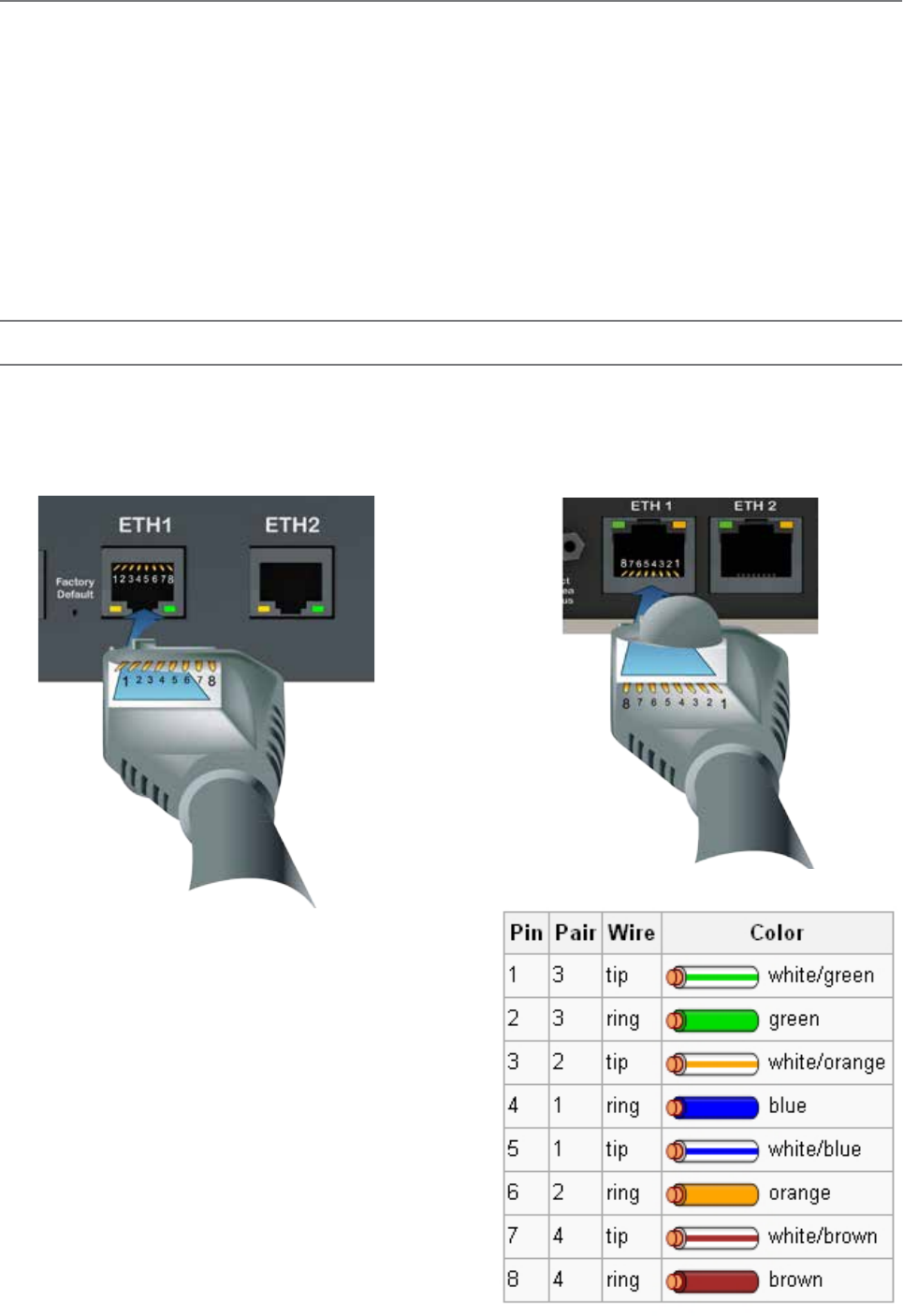
84 Document Number: 0100SM1401 Issue: 12-16
Connecting Antennas
The RF antenna system should be installed in accordance with the manufacturer’s instructions and local regulatory
requirements.
• The RF (Antenna) connector on the QR450 is a TNC type female connector.
• The RF (Antenna) connectors on the QR150 are user-configurable to operate in;
- Shared Tx/Rx mode on the TNC type female connector.
- Separate Tx on the TNC type female connector, and Rx on the SMA type female connector.
• The RF (Antenna) connectors on the QB and the QP are N-Type female connectors.
Good quality, low loss, feeder cable, should be considered according to the length of the cable run. Also, use a short, flexible
patch cable between the radio and lightning arrestor or flange mount of the radio cabinet/enclosure. Ensure that all external
connections are waterproofed.
Communication Ports
Ethernet Ports (ETH)
The ETH ports are 10/100 Base-T compliant, using RJ-45 sockets. These sockets support both TIA/EIA-568-A & B wiring as
they have Auto MDI/MDIX Auto Sensing. This means you can use both straight-through and cross-over type CAT-5 or better
patch cables. All RJ45 connectors should utilise mating plugs that include an integral locking tab.
If termination of a cable is required, then the following
wiring arrangement should be followed (Compliant with
TIA/EIA-568-A).
Maximum differential voltage : 5v, 50mA max through
each differential pair.
If 100-BaseT connection speed is required, CAT-6
Shielded cable should be used for installation to comply
with ETSI EMC directives.
QB / QP QR
Part F – Quick Reference Guide

85
Document Number: 0100SM1401 Issue: 12-16
Serial Ports - COM 1/2
The Q data radios feature a 9 pin miniature D-Shell (DE-9) Female connector that supports two individual serial port
connections. Each serial port is associated with an embedded serial terminal server that provides the serial to TCP/IP or UDP/
IP connectivity.
• COM 1 uses pins 2, 3, 7 & 8 with pin 5 as the common ground.
• COM 2 uses pins 4 & 6 with pin 5 as the common ground.
• An RSSI output is available on pin 9 which is useful for antenna alignment.
Pin out specs:
(1) Pin 2, 6 & 8 are outputs rated at +/- 6v, 65mA max.
(2) Pin 3, 4 & 7 are inputs rated at +/- 15v, 5mA max.
(3) Pin 9 is an analog voltage output to indicate the radio’s live RSSI measurement.
(4) Connecting wires should be #22 AWG (0.33mm2) or larger.
21 3 4 5
6 7 8 9
45 3 2 1
9 8 7 6
RS-232 Mode RS-485 Mode
Pin Name Input/Output Name Input/Output
1 COM 1 DCD Output Not Used -
2 COM 1 RxD Output B/Z (Inverting) Input/Output
3 COM 1 TxD Input A/Y (Non-Inverting) Input/Output
4 COM 2 TxD Input Not Used -
5 GND - Not Used -
6 COM 2 RxD Output Not Used -
7 COM 1 RTS Input Not Used -
8 COM 1 CTS Output Not Used -
9 RSSI Output RSSI Output
Part F – Quick Reference Guide
QB / QP QR450
21 3 4 5
6 7 8 9
QR150
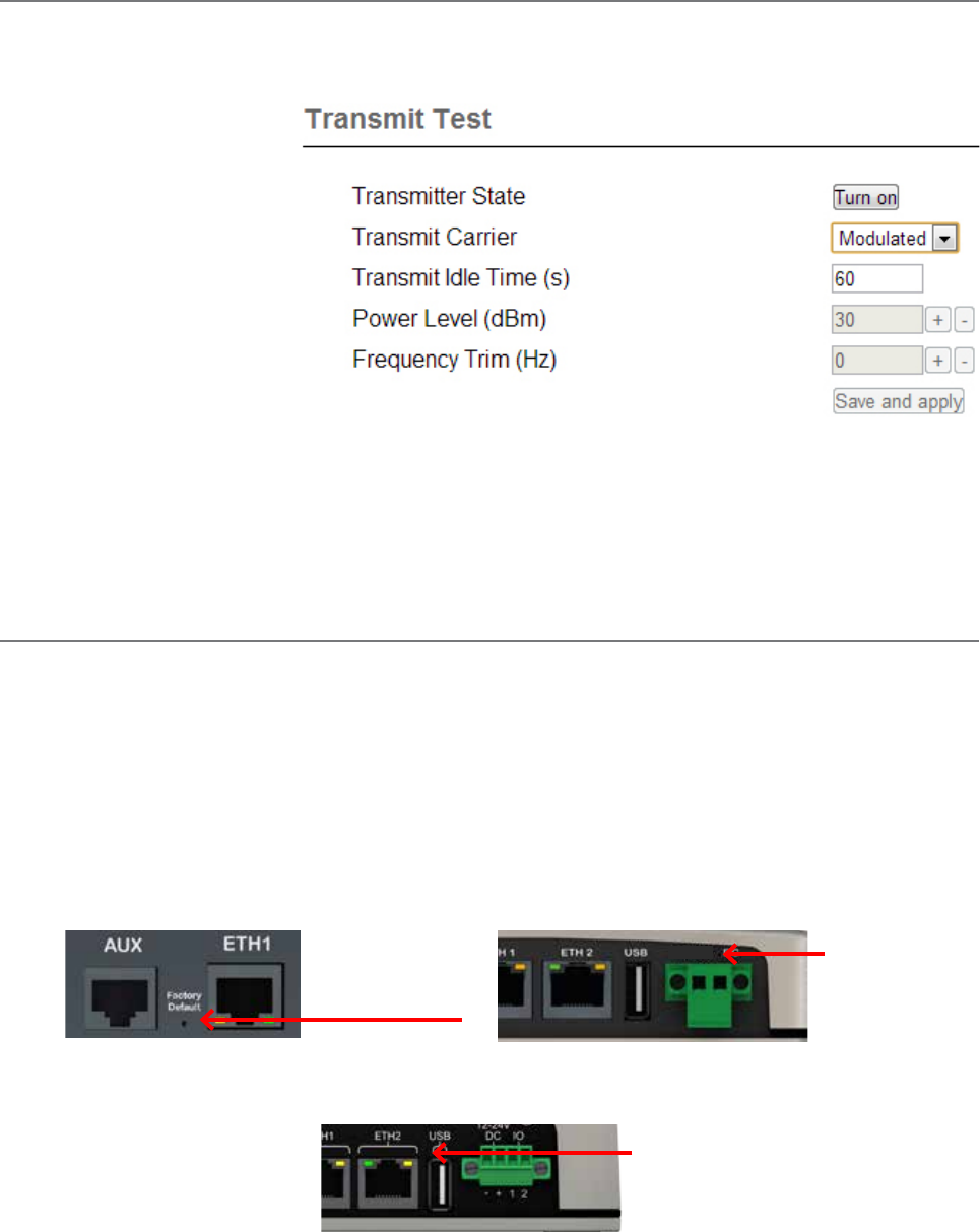
86 Document Number: 0100SM1401 Issue: 12-16
Activating Transmitter
Data sent to either of the radio’s communication ports (Ethernet or Serial Port) will cause the radio to key up it’s transmitter
and send the data over the air. However, to test the transmitter with external test equipment (Tx power, VSWR or Frequency),
or to test another radio’s receiver, the Q data radio provides a means to manually control the activation of the transmitter.
To access the transmit test tool,
access the radio’s web user interface
and browse to: Maintenance ->
Transmit Test. This will display the
transmit test tool page.
The transmitter can now be
controlled via this page. To key up
the transmitter, press the ‘Turn ON’
button. By default this will enable a
Modulated Carrier for 60 seconds.
During this time, the Tx LED should
illuminate solid RED to indicate the
transmitter is active.
If the power or frequency is adjusted, and it is desired to retain this value, the Save and apply button should be pressed to
activate the changes in the radio.
Factory Default
The factory default IP address of the Q data radios is 192.168.2.15. If you want to perform configuration changes on the Q
data radio and are not aware of the configured IP address, you may need to activate a factory reset. Alternatively, COM 1 can
provide access to the radio’s configuration via Text User Interface (as long as this port remains at the default configuration).
default interface settings are: 19200, N, 8, 1, No Handshaking.
A factory reset will cause all previous configuration settings to be erased and returned to the factory default values. A factory
default can be initiated by applying DC power to the radio (wait up to 3 minutes for the unit to fully boot up, indicated
by a solid GREEN Power LED), depress the factory default switch using a paper clip or similar object and keep the switch
depressed for 6 seconds or until all four LEDs illuminate solid GREEN and begin flashing, indicating the radio will return to the
factory default settings. Wait for up to 4 minutes for the factory default reset process to complete.
Factory Default
Switch
Factory Default
Switch
Part F – Quick Reference Guide
12-24
Factory Default
Switch
QB / QP QR450
QR150
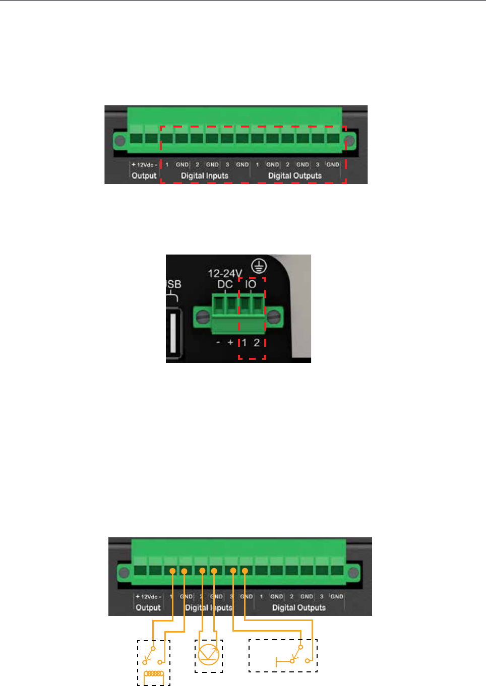
87
Document Number: 0100SM1401 Issue: 12-16
Digital I/O
The following Trio Q radios provide three dedicate Digital inputs as well as three digital outputs which can be read/written to
via TView+ Diagnostics or SNMP.
• QB Full Duplex Radio
• QH Hot Standby Full Duplex Radio
• QP Hot Standby Half Duplex Radio
Part F – Quick Reference Guide
Dry Contact
Electronic
Control
5V or
Floating
Driven Control
Typical Input Drivers
The QR150 provides two pins, dedicated for digital I/O. This I/O is user configurable, allowing each pin to be configured as
either a digital Input or a digital output.
QH / QB / QP
SNMP object descriptions for digital I/O can be found within the advanced section of this manual.
Inputs
The digital inputs for the QH/QB/QP & the QR150 have the same operational characteristics, the following input methods
can be used across either of these hardware variants.
Some form of switching contact (i.e: switch, relay) is normally used to change the state of the input. Both an isolated and
non-isolated input configuration is possible.
Typical input drivers include: dry contact (relay), electronic control or driven control. Each input can support either type of driver.
Reading the status of a user input while the circuit is CLOSED will report the input as being ON.
Reading the status of a user input while the circuit is OPEN (or not connected) will report the input as being OFF.
QR150
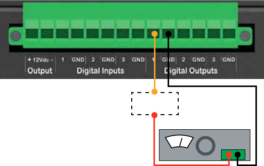
88 Document Number: 0100SM1401 Issue: 12-16
Part F – Quick Reference Guide
Outputs
The digital outputs for the QH/QB/QP & the QR150 have the same operational characteristics, the following output methods
can be used across either of these hardware variants. Each output is an open collector.
Power Specifications
Maximum Voltage allowed across each output is 30 Vdc.
Maximum current allowed through each output is 1A. External resistors or a current limited supply should be used
to keep the current below this value.
When the OUTPUT is OFF, The circuit will be OPEN. When the OUTPUT is ON, The circuit will be CLOSED.
Load
0V to 30V DC Supply
V
+ -
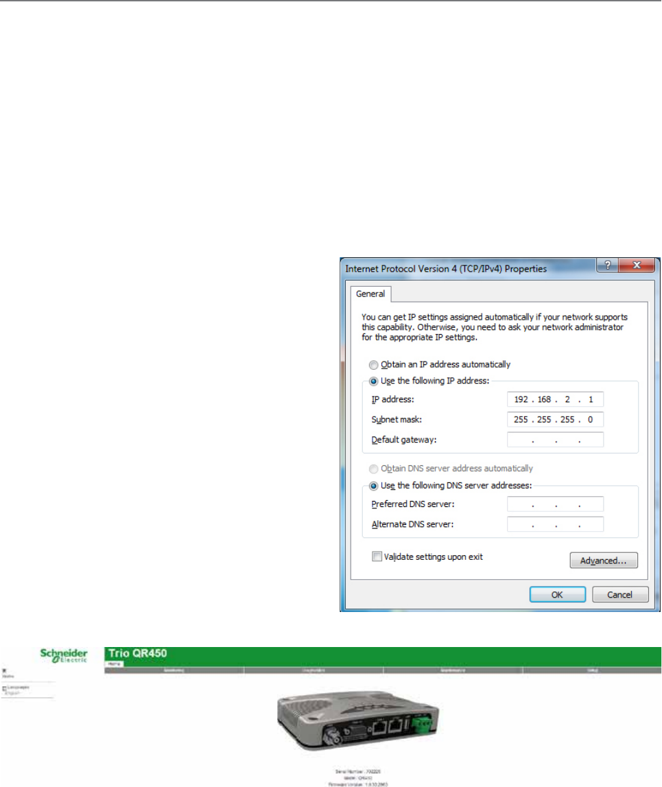
89
Document Number: 0100SM1401 Issue: 12-16
Connecting to Web User Interface (WUI)
Q data radios provide an embedded web server which provides access to the Web User Interface (WUI). The WUI can be used to
perform configuration changes on the radio. To change a configuration parameter in a Q data radio, connect a PC to one of the
Ethernet ports (ETH 1 or ETH 2) and direct a browser to the IP address of the Q data radio. It is strongly recommended that you
follow these guidelines for successful connection to the radio:
(1) Ensure that the Q data radio is powered up and has fully booted. This is indicated by a solid GREEN power LED. It takes
approximately 2 minutes from applying DC power for the Q data radio. Once the radio is fully booted, it may be indicating a user alarm.
For example, if the radio’s antenna port is incorrectly terminated, the radio will indicate a high VSWR alarm. Regardless of this user
alarm, the radio can still be browsed to.
(2) Disconnect the PC from any other Internet/LAN networks, as this may create a conflict in IP addresses or the Q data radio
IP might not fall within the subnet mask specified by the network.
(3) Connect the PC’s Ethernet Port to one of the Ethernet Ports (ETH 1 or ETH 2) using an RJ-45 patch cable. Cross over
cables will also work (Ethernet ports support MDI/MDIX). An active connection is indicated on the radio by solid green and
amber illumination on the LEDs which are fixed to the physical Ethernet port you are connected to.
(4) Ensure that the PC LAN Port is configured for a suitable
IP address. If you are using Windows 7, this can be done by
configuring the LAN settings via the Control Panel. Navigate to the
Windows “Start” button and open Control Panel -> Network and
Sharing Center -> Change adapter setting -> Double click on the
LAN port you are using -> Properties -> Double click ‘TCP/IPv4’.
You should see the window shown.
Ensure that “Obtain IP Address Automatically” is NOT selected.
It is recommended that you manually specify a compatible
IP Address. In this example, a factory default radio is being
configured. The IP address of that radio is 192.168.2.15 and a
compatible IP address for the PC would be 192.168.2.1. Click
OK to accept the changes.
Check with your Network Administrator before allocating IP
addresses as each LAN/WAN network is different.
(5) Now open the web browser and insert the IP address of the Q
data radio into the URL. In this case, we type “192.168.2.15”, the
browser should now display the home page of the radio. (Shown
below).
You may need to disable a web proxy (if in use) or disable or
modify the local firewall to help ensure the security.
Part F – Quick Reference Guide
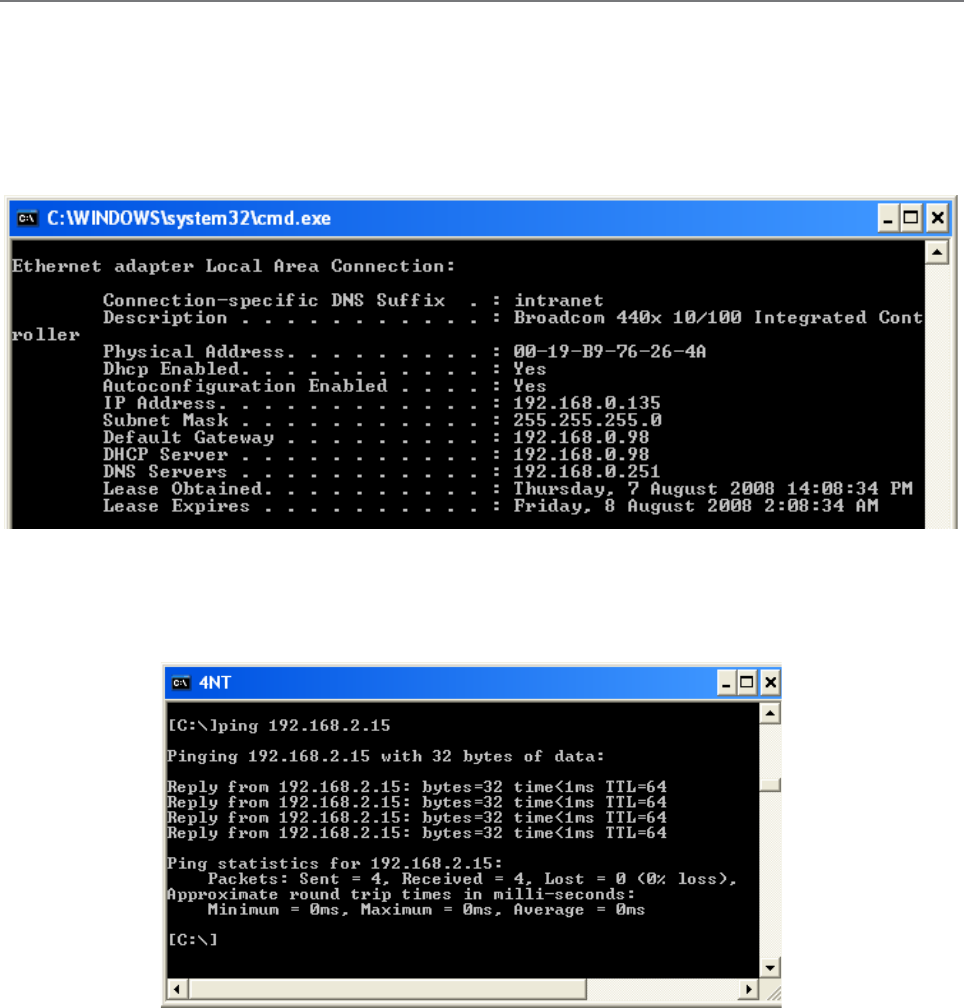
90 Document Number: 0100SM1401 Issue: 12-16
Resolving Ethernet Connection Issues
Here are some basic tips to help you along the way with Ethernet configuration issues. The Windows operating system (and
others) comes complete with many useful tools. First, you need to open a command window. This can be done by clicking on
“Start” then “Run” and entering “CMD” and clicking OK.
Obtaining IP information about your PC
If you need to find out more information about your computer’s Ethernet IP configuration, network gateways and DNS
servers, you can use a tool called “IPConfig”. Simply type “IPconfig /all” into the command window.
Checking IP connectivity
A reliable way to check IP connectivity to a device is using the “Ping” utility. Type “ping xxx” where xxx is the complete IP
address of the destination device you want to check. Ping will either respond with latency results (as shown) or say “timed
out” if no connection was possible.
Repeated connections to multiple devices with same IP address
A common issue experienced when attempting to configure multiple radios with the same IP address (such as factory default
radios). The issue is due to invalid MAC table entries. If you change the Ethernet connection between two devices with the
same IP address quickly, you may need to reset the MAC look up table in the PC. You can do this by typing “arp -d ” in the
command window.
Part F – Quick Reference Guide
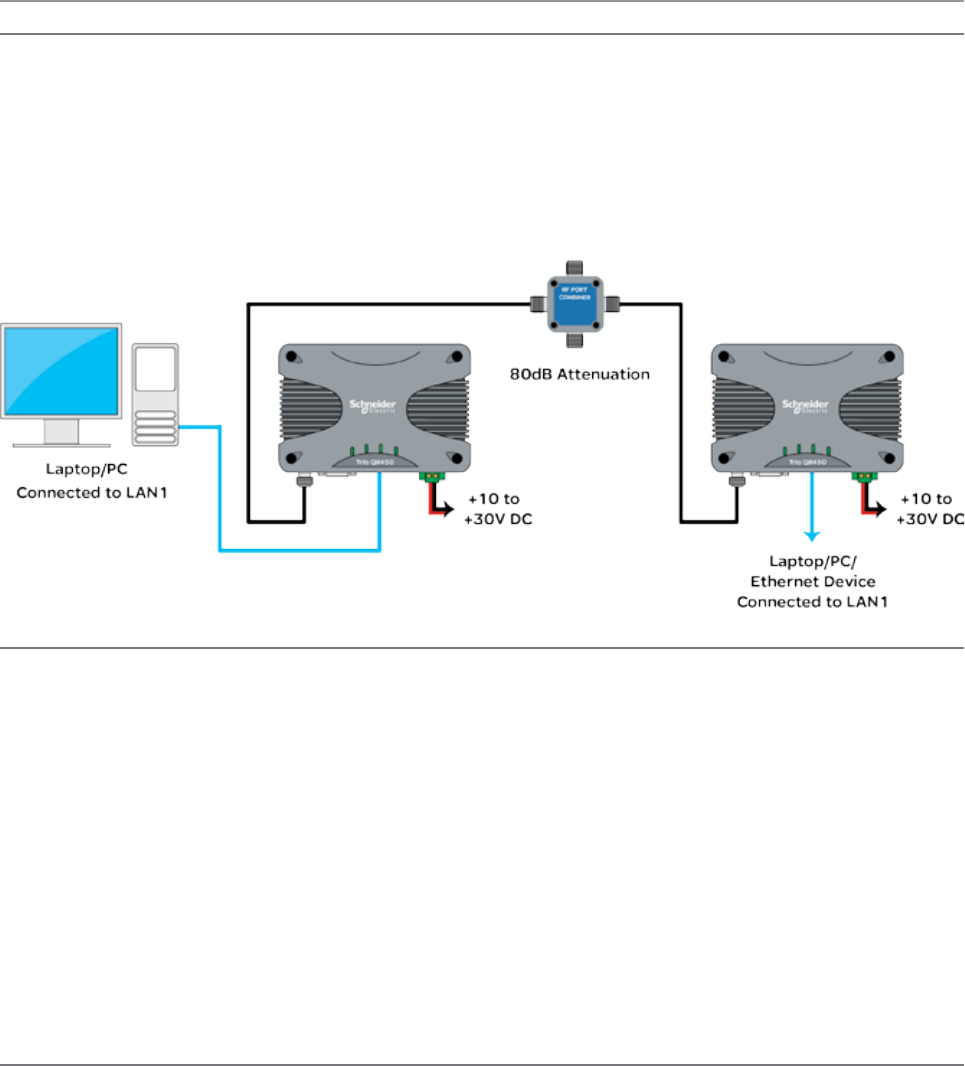
91
Document Number: 0100SM1401 Issue: 12-16
Part G– Quick Start Guide
Part G – Quick Start Guide
Step-by-Step Point to Point Setup
Introduction
This document describes the 10 key steps required for:
• Connecting and configuring a pair of Q data radios.
• Performing basic diagnostics and health checks
• Connecting user equipment such as Host Software and/or RTUs
Typical Bench setup
Step 1 - RF and DC power connection
RF Connection
Bench testing is typically performed over short distances, so RF signals need to be significantly attenuated. Using dummy
loads or whip antennas is not recommend.
A suitable method for attenuation of RF signals is to use a 4 Port RF Attenuator (Part Number TBUM4PORTATTEN). An
attenuator accurately reduces RF signal level, simulating a real world, long distance RF link. Other types of RF attenuators
can be used providing the total attenuation is between 80dB to 100dB. Check the attenuator power ratings against the
configured Tx power of the radio.
If the TX power of each radio is set to 20dBm (100mW) then, low power, low cost attenuators can be used.
DC Power Connection
Ensure that each radio is wired using the correct polarity and that power supply is regulated and has adequate current
delivering capacity. See the Quick reference guide section of this manual to confirm the power supply requirements you
require for the product you are using.
Step 2 - Power Up Radios
Apply DC power to the radios. The radio will begin a boot up process. This process can take up to 2 minutes (during this time
frame, the ‘Pwr’ LED will periodically flash GREEN, indicating that the boot up process is still in progress).
Once the boot up process has completed, the ‘Pwr’ LED should be solid GREEN. If there is no LED indication, re-check the DC
polarity and ensure that the DC voltage is between operating voltages.
If these checks are correct they you may need to inspect the internal fuse. Consult the maintenance section of this manual
for further information on fuse replacement.
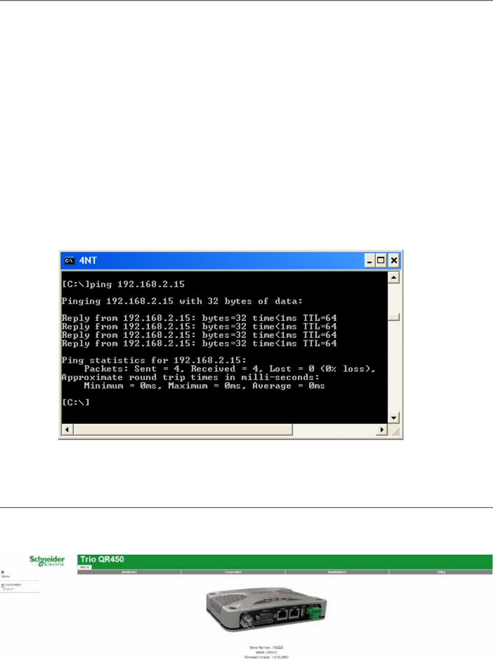
92 Document Number: 0100SM1401 Issue: 12-16
Step 3 - Setup for Radio Configuration
IP Address and Factory Default
The factory default IP address of the Q data radios is 192.168.2.15. If you want to perform configuration changes on the Q
data radio and are not aware of the configured IP address, you may need to activate a factory reset. Alternatively, COM 1 can
provide access to the radio’s configuration via Text User Interface (as long as this port remains at the default configuration).
default interface settings are: 19200, N, 8, 1, No Handshaking.
A factory reset will cause all previous configuration settings to be erased and returned to the factory default values. A factory
default can be initiated by applying DC power to the radio (wait up to 3 minutes for the unit to fully boot up, indicated
by a solid GREEN Power LED), depress the factory default switch using a paper clip or similar object and keep the switch
depressed for 6 seconds or until all four LEDs illuminate solid GREEN and begin flashing, indicating the radio will return to the
factory default settings. Wait for up to 4 minutes for the factory default reset process to complete.
Connection to Embedded Web User Interface (WUI) - HTTP
Connect the PC Ethernet Port to one of the Ethernet Ports (ETH1 or ETH2). To verify you can communicate with the QR you
should first ping the radio.
Open up a command window on the PC by going to the “Start” -> Run and typing “CMD” then OK. Then type “ping
192.168.2.15” which is the default address of the radio. The radio should respond to the ping as shown below. If this is not
the case, refer to the ‘Resolving Ethernet Connection Issues’ section in Part F of this manual.
Browse to the “Wizards” section of the WUI by clicking: -> Setup -> Wizards.
Step 4 - Start Web Browser on your PC
Start a web browser and insert the IP address of the radio into the URL. In this case, type “192.168.2.15” and the
configuration page is now displayed in the browser.
Q Data Radios can also be configured via a Text User Interface (TUI). Console protocols such as Telnet, SSH or a serial
connection may be used. For further details on making configuration changes via the TUI, refer to the advanced configuration
section of this manual.
Part G – Quick Start Guide
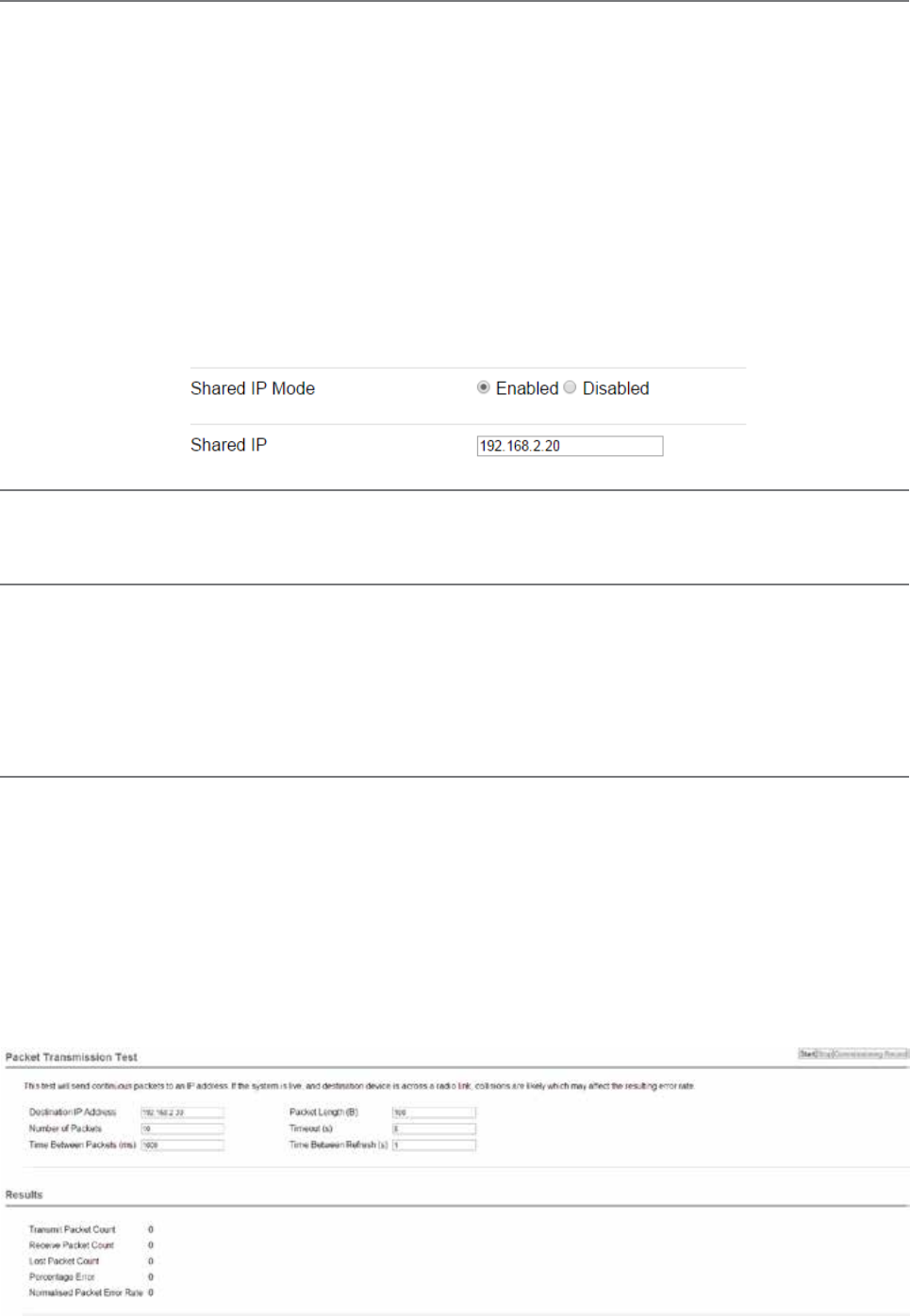
93
Document Number: 0100SM1401 Issue: 12-16
Step 5 - Activate Entry Point - PTP Wizard
Select Point to Point with Half Duplex Entry Point.
Select ‘Entry Point radio’ and click on the “Start The Wizard” button.
The Wizard now prompts the user to configure the minimum parameters to achieve point to point operation. For each
configuration item, help text is provided on the HTML programmer interface. If you are manually specifying IP addresses,
ensure that you record them for future reference. You will need to know the IP address of each radio in future steps.
After configuration of all items are complete, activate the configuration by clicking on the “Activate Configuration” button in
the top right corner.
Step 6 - Activate Remote - PTP Wizard
Repeat steps (3) to (5) for the Remote radio. When in Step 5, select the ‘Remote radio’ button and click on the ‘Start The
Wizard” button. ‘
Step 7 - Verify Modem Operation
The radio configuration & RF link can now be verified for correct operation. First, check that the remote radio can correctly
decode a transmitted signal. This is done by energising the transmitter (modulated carrier) of the entry point radio. Refer to
the instructions about this in the quick reference guide section of this manual.
With the transmitter energised, inspect the LED status on each radio. The entry point radio should have a solid RED ‘Pwr/Tx’ LED.
The remote radio should a solid GREEN ‘Sync/RxSig’ LED. If this LED is not SOLID green it may indicate incorrect configuration or
inadequate signal strength and the setup should be checked. Repeat this test with the Remote radio transmitting.
Part G – Quick Start Guide
Step 8 - Packet Transmission Test
This tool provides a useful way to test a radio communications link by transmitting data packets between two units in a loop-
backed mode.
You can find this tool in the “Diagnostics” tab, then click on the “Packet Transmission Test” sub-menu.
Enter the “Destination IP Address” field with the IP address of the of the target radio that you want to ping. Ensure that the
“Number of Packets” is set to 1000. Now click on the “Start Packet Test” button. The radio will indicate the packet test has
started and is currently running and both units will have flashing Tx LEDs indicating data is being transmitted.
When the test is complete, a message stating “Packet transmission test completed” will be shown and the test results
summarised in the “Test Results” section.
The test results show TX & RX Packets, Lost Packets and the Packet Error Rate.
Shared IP Address (Optional Configuration - For Hot Standby units only)
Radio A and Radio B (within the QP) can be configured to ‘share’ an IP address. This is a separate IP address from each
radio’s unique IP address. The shared IP address can be used to access the current ‘online’ radio.
The shared IP address should be configured in each individual internal radio as the same IP address.
To configure the shared IP address, go to: Setup -> Basestation -> General and enable Shared IP Mode.
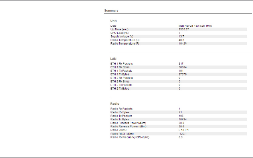
94 Document Number: 0100SM1401 Issue: 12-16
Step 9- Embedded Diagnostics Testing
8.1 Review Diagnostics
Connect the web browser to the Entry Point radio
using the IP address recorded in Step 5. Once
loaded, click on the Diagnostics tab, then select
the summary sub-menu. This will display the
Diagnostics summary page. Review the diagnostics
parameters checking for abnormal items such as
high VSWR (high TX reverse power) and lower than
expected radio RSSI (Received Signal Strength).
Follow this step again for the Remote radio.
Step 10 - Commissioning Record
After a packet transmission test has been performed, a Commissioning Record can be prepared. This facility is activated by
clicking on the “Commissioning Record” button.
It is recommended that the radio is configured to use the current date (either time configured manually or obtained from an
NTP server) otherwise the date / time shown will not be correct.
The user can enter an appropriate Unit Name and Location for reference purposes. Additionally, a comment may be added
noting the type of antenna in use. Once this information has been added, the web page can be printed (using the print facility
in the web browser). It may be useful to print the commissioning record to PDF for future reference.
This now completes the requirements for setting up a half duplex, Point to Point Q Data Radio Link. The radios are now ready for
application testing. The application can be connected to either ETH1 or ETH2 or both.
Part G – Quick Start Guide
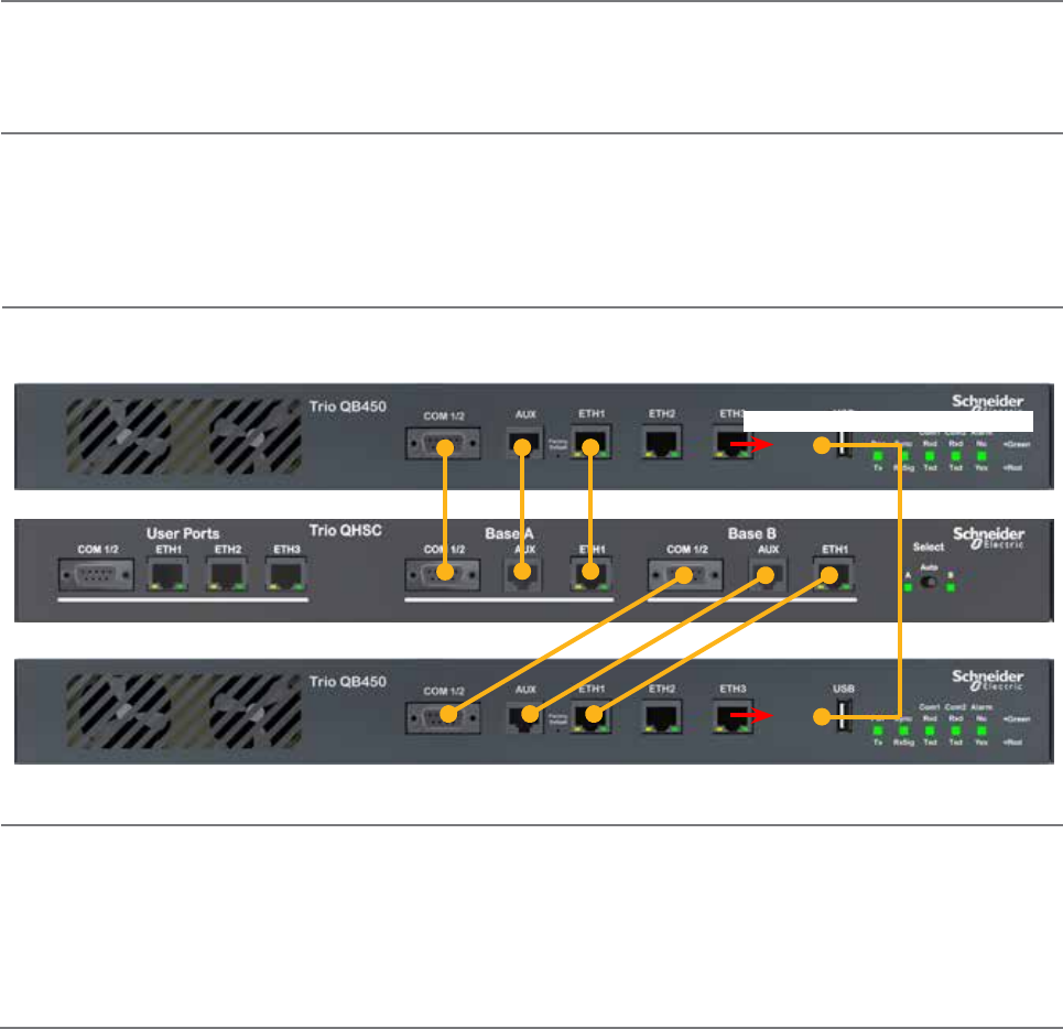
95
Document Number: 0100SM1401 Issue: 12-16
QH Hot Standby Quick Start Guide
Introduction
This document describes the seven key steps required for connecting and configuring a single QH arrangement.
Step 1 - RF and DC power connection
Connect the DC power and Antenna ports following the connection diagrams shown in the QH Quick Reference Guide section.
If antennas are not available, terminate the radios antenna ports with a suitable load or attenuator.
Do not apply DC power to the hot standby arrangement at this stage.
Step 3 - Apply DC Power
Ensure that the radio select switch on the hot standby controller is switched to Radio A.
Apply DC power to the hot standby arrangement, allowing up to two minutes for the radios to power up.
Once the hot standby arrangement is powered up (indicated by a solid green LED state on the pwr LEDs), ensure that the
HSC radio select LED for Radio A is illuminated amber. This indicates that Radio A is forced online.
Step 4 - Start Web Browser on your PC
Ensure that each QB radio is in factory default state. This is done by depressing the hidden factory default button on the front
panel of each QB for 5 seconds. Allow up to three minutes for the factory default process to complete.
Connect your PC Ethernet port to the ETH 2 interface of Base A. Verify that your PC can communicate with Base A by
performing a ping test. The default IP address of a Q data radio is 192.168.2.15.
Start a web browser and insert the IP address of the radio into the URL. In this case, type “192.168.2.15” and the
configuration page should now be displayed in the browser.
Further details on factory default and WEB browser connection can be found in the QB Quick Start Guide.
Step 2 - Interface Connections
Connect the interface cables following the diagram below (leaving the QB interconnecting cable [ETH3-ETH3] disconnected).
Part G – Quick Start Guide
Leave ETH3-ETH3 disconnected
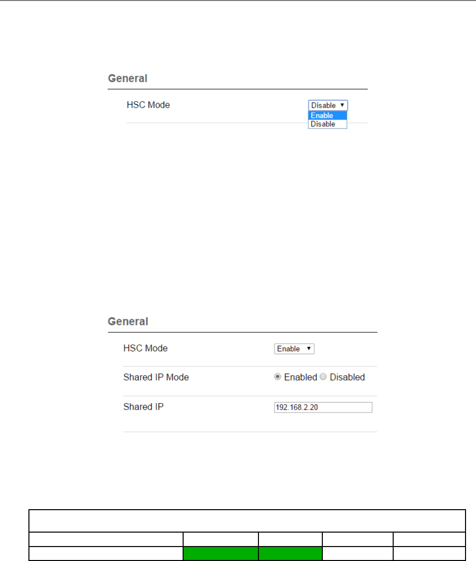
96 Document Number: 0100SM1401 Issue: 12-16
Step 5 - Radio Configuration
There are three main QB configuration parameters to review for hot standby operation:
• HSC Mode: Configure the QB to operate within a hot standby arrangement by enabling HSC mode. To access HSC
mode, go to: Setup -> Basestation -> General and enable the HSC Mode. Once HSC Mode is enabled, a range of hot
standby configuration parameters becomes available.
• Unique IP Address: Each QB radio within a hot standby arrangement requires its own unique IP address. To configure
the IP address, go to: Setup -> Network -> Ethernet -> IP Address . For this example, the following unique IP address
allocations have been given:
- Base A IP: 192.168.2.21
- Base B IP: 192.168.2.22
• Shared IP Address: The two QB radios within a hot standby arrangement can be configure to ‘share’ an IP address.
This is an IP address separate from the radio’s unique IP address. The ‘online’ base within the hot standby arrangement
assumes ownership of the shared IP address. The shared IP address has to be configured in Base A & B.
To configure the shared IP address, enable HSC mode, then go to: Setup -> Basestation -> General and enable Shared IP Mode.
For this example, the following shared IP address has been allocated:
- Base A & B Shared IP: 192.168.2.20
When these parameters have been configured, activate the configuration.
Once the configuration is activated Base A will attempt to negotiate and pair with an alternate QB. As Base B is still in a
factory default state, HSC mode negotiation messages will be ignored (until HSC mode is enabled). This will cause Base A to
indicate a pairing alarm, which can be ignored until Base B has been configured.
QB (within a QH)
Alarm Type Pwr / Tx Sync / NoRx COM 1 RxD / TxD COM 2 RxD / TxD
Pairing Alarm Green Green
When Base A has been successfully configured, perform the following steps:
- Force Base B online using the radio select switch on the QHHSC
- Begin from Step 4 and configure Base B
Part G – Quick Start Guide
[For further details on alarms, refer to Part F - Quick Reference Guide]
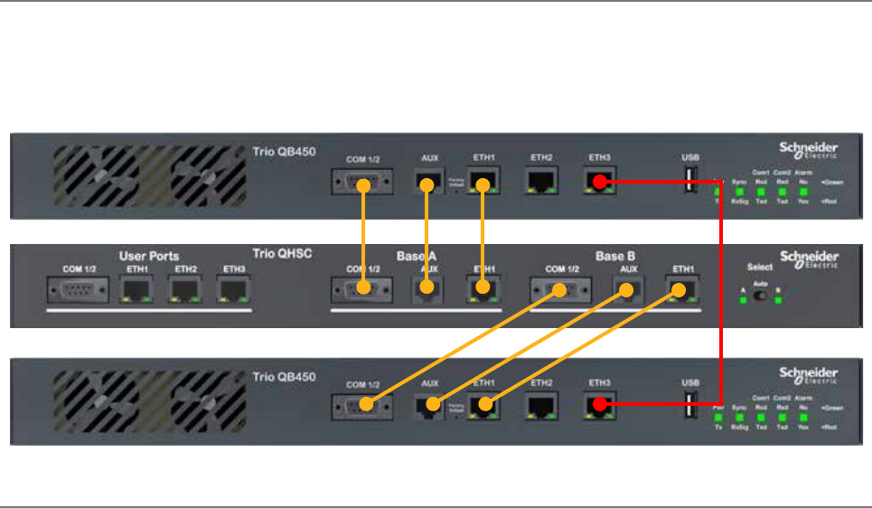
97
Document Number: 0100SM1401 Issue: 12-16
Step 6 - Base Interconnection
When Base A and Base B have both been successfully configured, interconnect the ETH 3 interfaces of both Bases. The
cable is shown in the diagram below in RED. Once this cable is in place, each base should be able to successfully negotiate
with one another and the pairing alarms should stop.
When the cable has been connected, set the radio select switch on the QHHSC to the Auto position.
Step 7 - Change-over triggers
When the alarm output becomes active on the online QB, a change-over can occur (as long as the alternate QB does not
also have an active alarm output). The alarm output can become active when an alarm is detected. The alarms are user-
configurable and can be subscribed to the alarm output.
By default, no alarms are subscribed to the alarm output. It is recommended to review the alarms setup in each base, to
ensure that suitable alarms have been subscribed to the alarm output for the given system requirements. If the system
requirements are unknown, all of the alarms can be subscribed to the alarm output, then disabled in the future, if no longer
required.
Refer to the advanced section of this manual for further information on configuring radio alarms.
Part G – Quick Start Guide
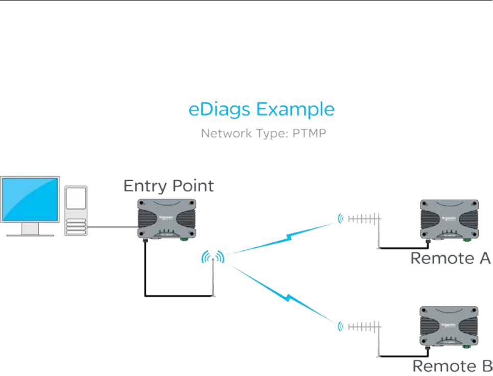
98 Document Number: 0100SM1401 Issue: 12-16
Diagnostics entry point radio
Local IP: 192.168.2.16
eDiags Local IP Port: 1040
The following instructions will explain how to poll Q data radios using eDiags over a wireless network.
(1) Enable eDiags within each radio that is required to be polled. Configure the following parameter in each radio:
• Local Port number - This will be the port number the eDiags session (within the PC) will address all eDiags data to
(example uses: 1040)
(2) Ensure that TView+ Diagnostics software has been installed on the PC
(3) Open the TView+ Diagnostics software on the PC and configure the following items (for detailed instructions on the
TView+ Diagnostics software, refer to the TView+ Diagnostics user manual):
• Create a list (database) of Q data radios that are required to be polled for diagnostics. Each data base entry should have
the communications port set to eDiags (Ethernet) and configured to use the IP address and eDiags port number of the
corresponding radio. Each serial number entered needs to be correct. Other information can also be specified.
• Define the IP address and local listening port number for the eDiags session (controller address and port number). This
can be configured in Settings -> eDiags Port settings. The IP address and port number configured, needs to match the
controller IP address and controller port number specified within the eDiags settings within each of the radios (they
should all have common settings).
This now completes the requirements for configuring eDiags. The operation of eDiags for a typical poll/response diagnostics
transaction is as follows:
(1) The TView+ Diagnostics software constructs a UDP/IP data gram which targets the embedded eDiags server of each radio
configured within the database.
(2) The UDP datagram is placed onto the LAN/WAN which routes the datagram onto the radio network.
(3) The entry point radio will respond to any poll addressed to it’s own IP address and eDiags port, or, will transmit the poll
over the air to the targeted radio.
(4) The targeted radio will then respond to the poll, by transmitting a response, which will be sent back to the controller
address (the Diagnostics PC).
PC running TView+ Diagnostics
PC Local IP: 192.168.2.1
eDiags Local Listen port: 1040
Step-by-Step eDiags Setup
Ethernet diagnostics (also known as eDiags) is a feature of the TView+ diagnostics software that encapsulates the TView+
diagnostics protocol in an Ethernet UDP/IP packet. Together with the eDiags server embedded into each Q data radio, the
user can monitor a Q data radio network using the TView+ diagnostics software over an Ethernet LAN/WAN. A typical use
diagram is shown below.
For more information on the features, benefits and technical details of the TView+ diagnostics software, refer to the TView+
diagnostics user manual.
Remote A
Local IP: 192.168.2.17
eDiags Local IP Port: 1040
Remote B
Local IP: 192.168.2.18
eDiags Local IP Port: 1040
Part G – Quick Start Guide
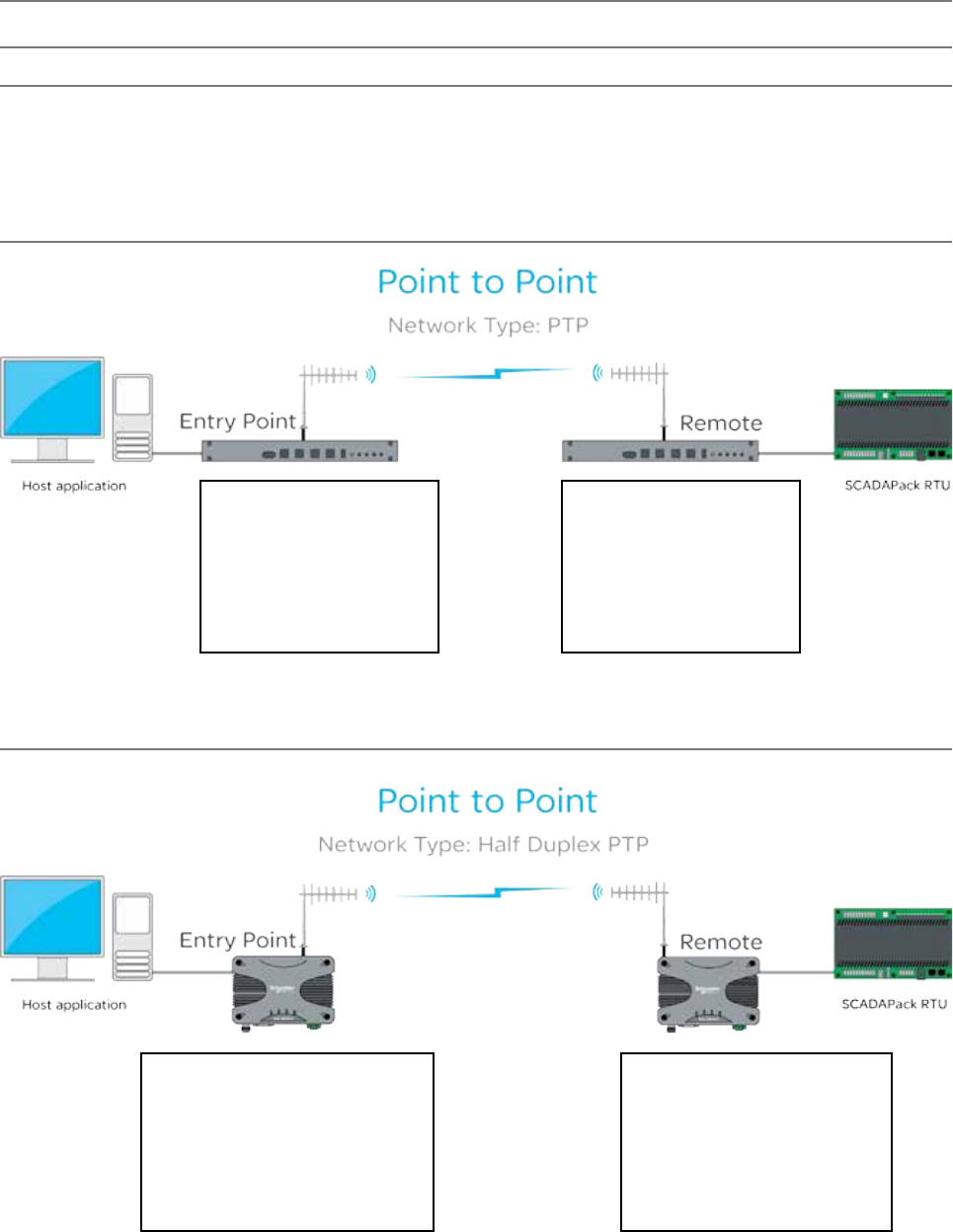
99
Document Number: 0100SM1401 Issue: 12-16
System Topology Configuration
Transparent Bridge Mode
Full Duplex Entry Point
Radio Settings:
Operating Mode: Bridge Mode
Collision avoidance: Disabled
RF Data Rate: Dynamic
Network Settings:
IP: 192.168.2.20/24
Full Duplex Remote
Radio Settings:
Operating Mode: Bridge Mode
Collision avoidance: Disabled
RF Data Rate: Dynamic
Network Settings:
IP: 192.168.2.21/24
Introduction
The following Diagrams are designed to provide configuration information on typical topologies. The channel bandwidth and
Tx/Rx frequencies are not shown within the diagrams, as they depend on the users license.
The following diagrams show ‘/24’ after an IP address. This short hand addressing indicates the device’s subnet mask. ‘/24’
equals a subnet mask of 255.255.255.0
Point to Point - Full Duplex
Point to Point - Half Duplex
Half Duplex Entry Point
Radio Settings:
Operating Mode: Bridge Mode
Collision avoidance: Carrier Detect
RF Data Rate: Dynamic
Network Settings:
IP: 192.168.2.20/24
Half Duplex Remote
Radio Settings:
Operating Mode: Bridge Mode
Collision avoidance: Carrier Detect
RF Data Rate: Dynamic
Network Settings:
IP: 192.168.2.21/24
Part G – Quick Start Guide
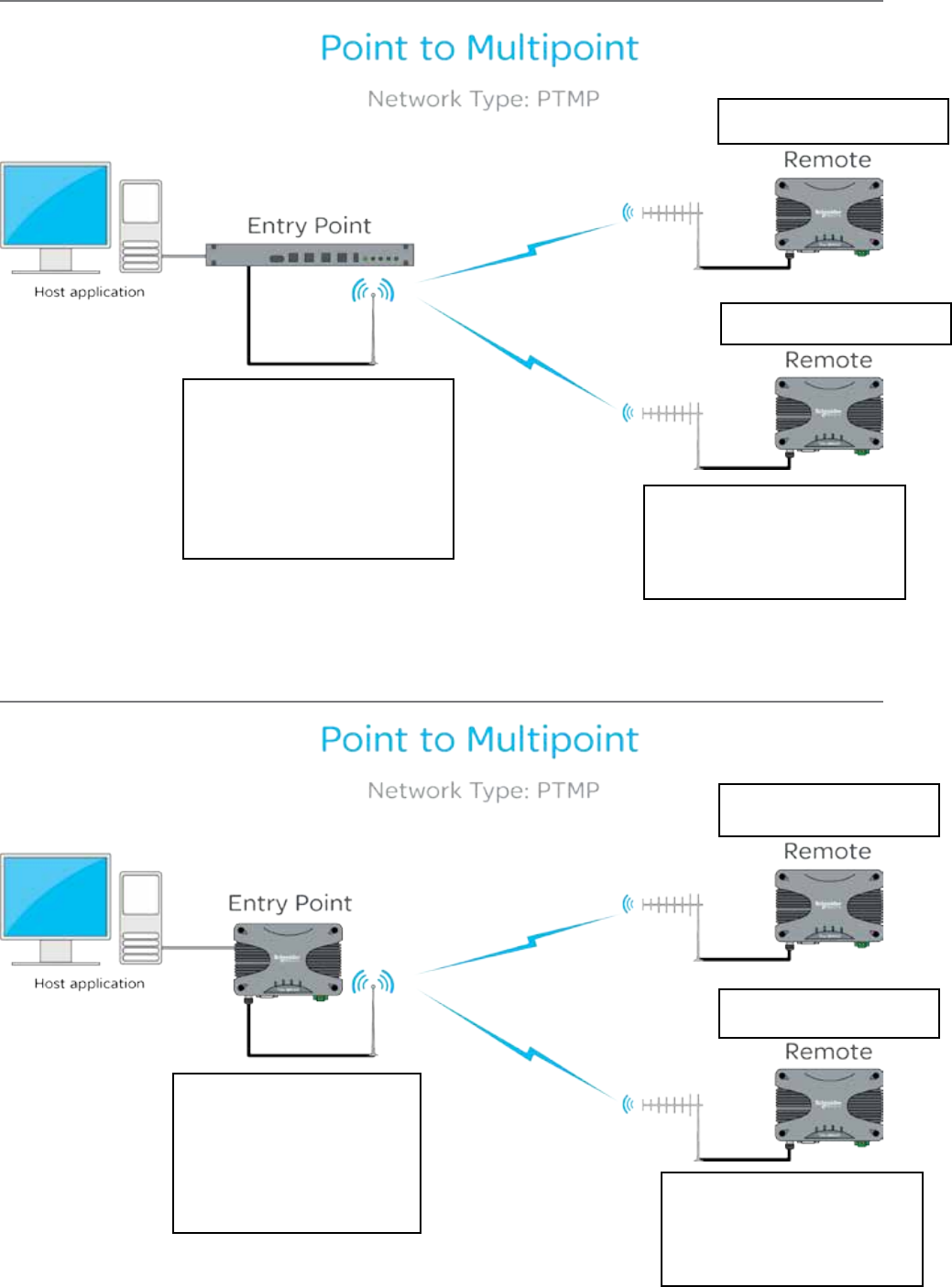
100 Document Number: 0100SM1401 Issue: 12-16
Point to Multipoint - Full Duplex Entry Point
Point to Multipoint - Half Duplex Entry Point
Full Duplex Entry Point
Radio Settings:
Operating Mode: Bridge Mode
Collision avoidance: Digital
Collision avoidance Master: Enabled
RF Data Rate: Dynamic
Network Settings:
IP: 192.168.2.20/24
Half Duplex Remotes
Radio Settings:
Operating Mode: Bridge Mode
Collision avoidance: Digital
RF Data Rate: Dynamic
Remote Network Settings:
IP: 192.168.2.21/24
Remote Network Settings:
IP: 192.168.2.22/24
Half Duplex Entry Point
Radio Settings:
Operating Mode: Bridge Mode
Collision avoidance: Carrier Detect
RF Data Rate: Dynamic
Network Settings:
IP: 192.168.2.20/24
Half Duplex Remotes
Radio Settings:
Operating Mode: Bridge Mode
Collision avoidance: Carrier Detect
RF Data Rate: Dynamic
Remote Network Settings:
IP: 192.168.2.21/24
Remote Network Settings:
IP: 192.168.2.22/24
Part G – Quick Start Guide
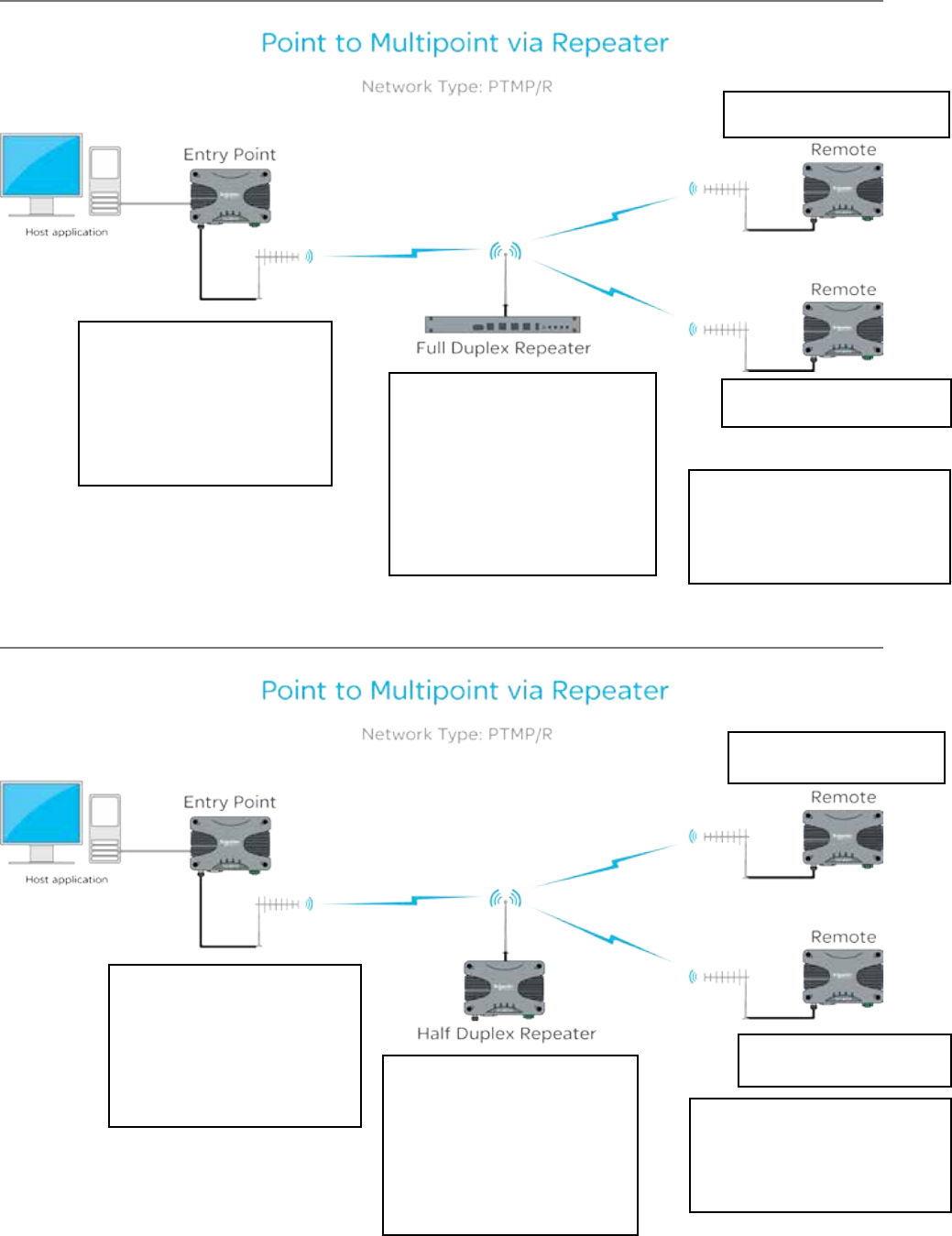
101
Document Number: 0100SM1401 Issue: 12-16
Point to Multipoint via Repeater - Full Duplex Repeater
Point to Multipoint via Repeater - Half Duplex Repeater
Full Duplex Repeater
Radio Settings:
Operating Mode: Bridge Mode
Peer to peer repeat: Enabled
Collision avoidance: Digital
Collision avoidance Master: Enabled
RF Data Rate: Dynamic
Network Settings:
IP: 192.168.2.21/24
Half Duplex Remotes
Radio Settings:
Operating Mode: Bridge Mode
Collision avoidance: Digital
RF Data Rate: Dynamic
Remote Network Settings:
IP: 192.168.2.22/24
Half Duplex Entry Point
Radio Settings:
Operating Mode: Bridge Mode
Collision avoidance: Digital
RF Data Rate: Dynamic
Network Settings:
IP: 192.168.2.20/24
Remote Network Settings:
IP: 192.168.2.23/24
Half Duplex Repeater
Radio Settings:
Operating Mode: Bridge Mode
Peer to peer repeat: Enabled
Collision avoidance: Carrier Detect
RF Data Rate: Dynamic
Network Settings:
IP: 192.168.2.21/24
Half Duplex Remotes
Radio Settings:
Operating Mode: Bridge Mode
Collision avoidance: Carrier Detect
RF Data Rate: Dynamic
Remote Network Settings:
IP: 192.168.2.22/24
Half Duplex Entry Point
Radio Settings:
Operating Mode: Bridge Mode
Collision avoidance: Carrier Detect
RF Data Rate: Dynamic
Network Settings:
IP: 192.168.2.20/24
Remote Network Settings:
IP: 192.168.2.23/24
Part G – Quick Start Guide
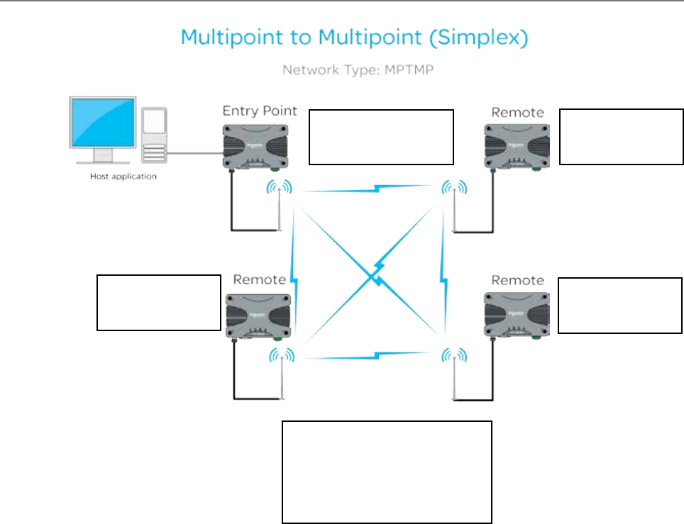
102 Document Number: 0100SM1401 Issue: 12-16
Multipoint to Multipoint
All Radios
Radio Settings:
Operating Mode: Bridge Mode
Simplex Parameters: PTP or MPTMP
Collision avoidance: Carrier Detect
RF Data Rate: Dynamic
Half Duplex Entry Point
Network Settings:
IP: 192.168.2.20/24
Remote
Network Settings:
IP: 192.168.2.21/24
Remote
Network Settings:
IP: 192.168.2.22/24
Remote
Network Settings:
IP: 192.168.2.23/24
Part G – Quick Start Guide
103
Document Number: 0100SM1401 Issue: 12-16
Static Routes
While operating in IP routing mode, a radio to must be configured with a manually populated static route table.
That static route table can be accessed via Setup -> IP Routing (only available while radio operating mode is set to IP
Routing).
To add a new route to the table, select the ‘Add’ button. This will add a new, empty table entry, which will need to be manually
populated with a static route. The added routes must be populated in an acceptable format. Route formatting information is
shown below.
Formatting a static route
There are multiple formatting methods in which static route rules can be written.
Routing rules may define a forwarding path to a gateway or to an interface (LAN or WAN) which is shown in the examples
below as <Gateway IP or ”LAN” or ”WAN”>.
Examples:
Using a network address and a subnet mask to define a range of target IP addresses to be forwarded to a gateway
Route Format: <Network Address> <Netmask> <Gateway IP or ”LAN” or ”WAN”>
Example: 192.168.1.0 255.255.255.0 10.10.10.1
Using the CIDR format, a range of IP address may be routed to a specified gateway. The range may include the multicast
address space. The network address must be valid (base address of the range) defined by the CIDR prefix.
Route Format: <Network Address/CIDR> <Gateway IP or ”LAN” or ”WAN”>
Example: 192.168.1.0/24 10.10.10.1
A single host or multicast address can be defined and routed to a gateway or an interface as described above.
Route Format: <IP Address> <Gateway IP or ”LAN” or ”WAN”>
Example: 192.168.1.20 10.10.10.1
For each multicast address required to traverse from one interface to another or to effect a store and forward, a route
instruction is required. (Where square brackets represent optional route entry parameters.
Route Format: <Multicast IP Address> [FROM IP Address] “WAN” or ”LAN” “WAN” or ”LAN” [“WAN” or ”LAN”]
Example: 224.240.1.1 192.168.1.40 WAN WAN LAN
There may only be one occurrence of LAN in the rule above.
A second occurrence of WAN will effect a store and forward action.
All routes can also have comments added to them. Comments can be added to the end of each route by prefixing the
comment text with an exclamation mark ‘!’.
Example: 192.168.1.0/24 10.10.10.1 !Mountain Top Route
Part G – Quick Start Guide
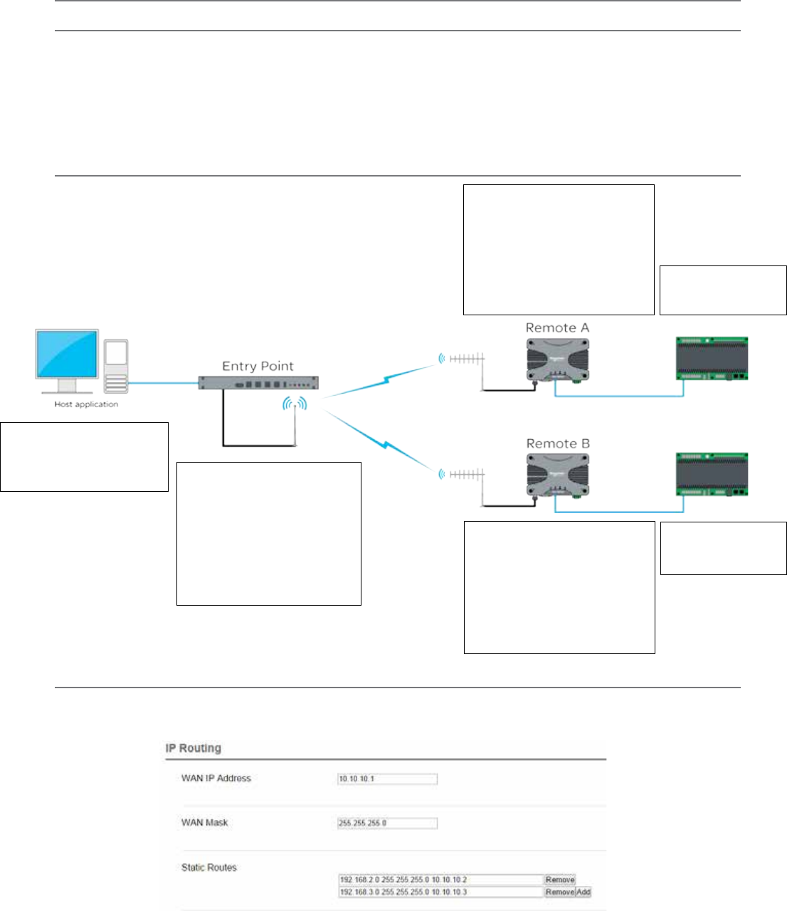
104 Document Number: 0100SM1401 Issue: 12-16
Router Mode
Point to Multipoint - Full Duplex Entry Point
Full Duplex Entry Point
Network Settings:
IP Address: 192.168.1.1/24
Router Settings:
WAN IP Address: 10.10.10.1/24
Route Table Entries:
192.168.2.0/24 10.10.10.2
192.168.3.0/24 10.10.10.3
Host Application
Network Settings:
IP Address: 192.168.1.10/24
Gateway: 192.168.1.1
Remote A
Network Settings:
IP: 192.168.2.1/24
Router Settings:
WAN IP Address: 10.10.10.2/24
Route Table Entries:
192.168.1.0/24 10.10.10.1
Remote B
Network Settings:
IP: 192.168.3.1/24
Router Settings:
WAN IP Address: 10.10.10.3/24
Route Table Entries:
192.168.1.0/24 10.10.10.1
Ethernet Device
IP: 192.168.2.2/24
Gateway: 192.168.2.1
Ethernet Device
IP: 192.168.3.2/24
Gateway: 192.168.3.1
Introduction
The following Diagrams are designed to provide configuration information on typical topologies. The channel bandwidth and
Tx/Rx frequencies are not shown within the diagrams, as they depend on the users license.
The following diagrams show ‘/24’ after an IP address. This short hand addressing indicates the device’s subnet mask. ‘/24’
equals a subnet mask of 255.255.255.0. Short hand addressing can be used when writing a static route.
For details on static route formatting, refer to the advanced section of this manual.
Part G – Quick Start Guide
IP Route Configuration Example - Full Duplex Entry Point
In relation to the diagram above (Point to Multipoint - Full Duplex Entry Point) the following example shows how the IP Routing
configuration would appear within the Full Duplex Entry Point radio.
For detailed information regarding route table entries, refer to the Static Routes section of Part G within this manual.
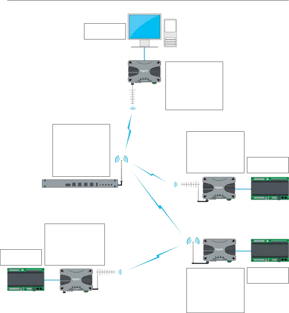
105
Document Number: 0100SM1401 Issue: 12-16
Point to Multipoint via multiple Repeaters
Host Application
IP: 192.168.1.2/24
Gateway: 192.168.1.1
Entry Point
Network Settings:
IP: 192.168.1.1/24
Router Settings:
WAN IP: 10.10.10.1/24
Route Table Entries:
192.168.3.0/24 10.10.10.2
192.168.4.0/24 10.10.10.2
192.168.5.0/24 10.10.10.2
Full Duplex Repeater
Network Settings:
IP: 192.168.2.1/24
Router Settings:
WAN IP: 10.10.10.2/24
Route Table Entries:
192.168.1.0/24 10.10.10.1
192.168.3.0/24 10.10.10.3
192.168.4.0/24 10.10.10.4
192.168.5.0/24 10.10.10.4
Ethernet Device
IP: 192.168.3.2/24
Gateway: 192.168.3.1
Ethernet Device
IP: 192.168.5.2/24
Gateway: 192.168.5.1
Ethernet Device
IP: 192.168.4.2/24
Gateway: 192.168.4.1
Remote B
Network Settings:
IP: 192.168.5.1/24
Router Settings:
WAN IP: 10.10.10.5/24
Route Table Entries:
192.168.1.0/24 10.10.10.4
Remote A
Network Settings:
IP: 192.168.3.1/24
Router Settings:
WAN IP: 10.10.10.3/24
Route Table Entries:
192.168.1.0/24 10.10.10.2
Half Duplex Repeater
Network Settings:
IP: 192.168.4.1/24
Router Settings:
WAN IP: 10.10.10.4/24
Route Table Entries:
192.168.1.0/24 10.10.10.2
192.168.5.0/24 10.10.10.5
Part G – Quick Start Guide
For detailed information regarding route table entries, refer to the Static Routes section of Part G within this manual.
This topology should use Carrier detect collision avoidance.
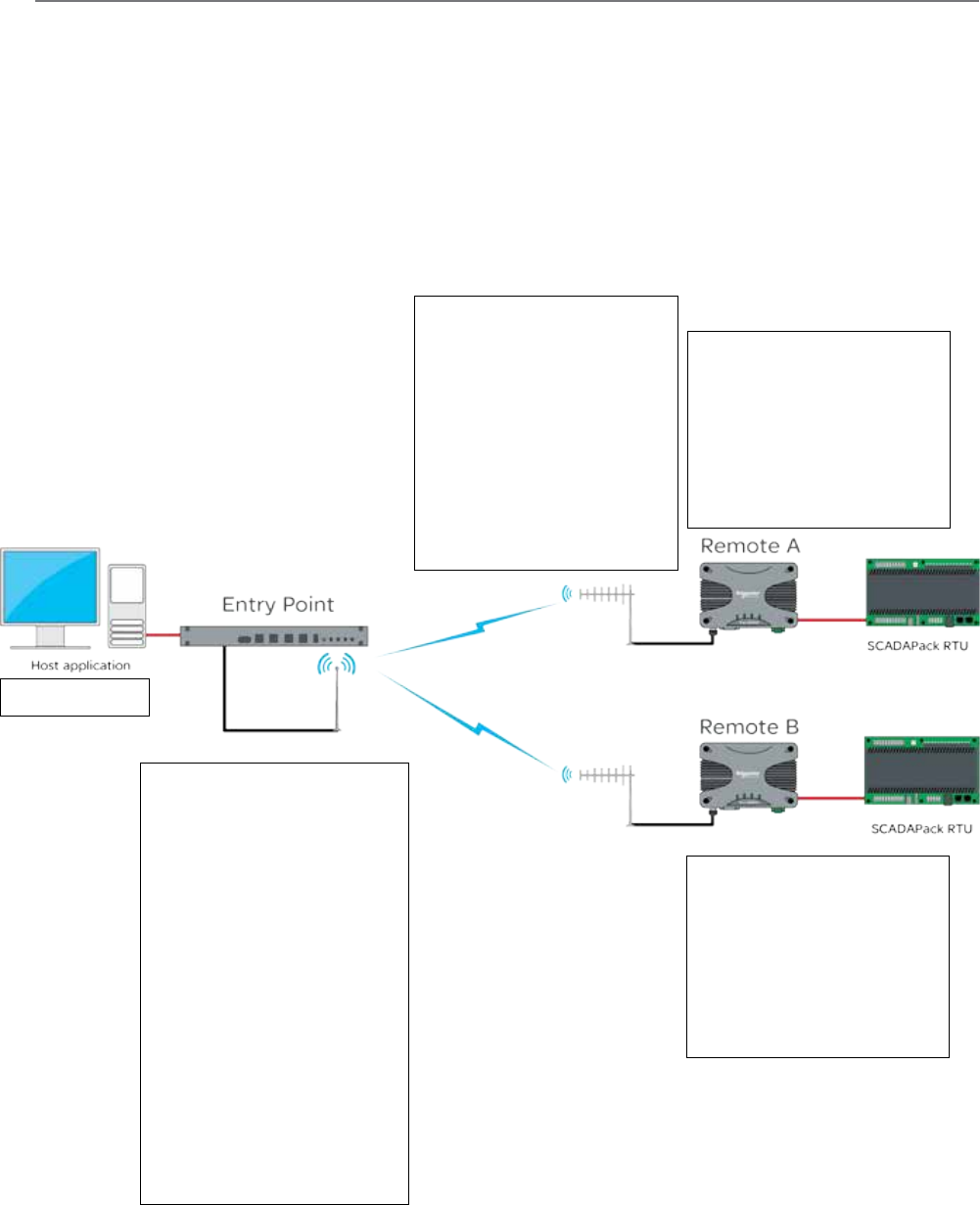
106 Document Number: 0100SM1401 Issue: 12-16
IP Routing - Serial Data PTMP
As serial data uses the embedded device server (or MODBUS Gateway) the data sent over the air can also be routed. The example
below shows a PTMP topology, where the entry point radio is performing the following functions:
- Encapsulating serial data in IP frames.
- Addressing these IP frames to a multicast address.
- Forwarding the multicast frames on to the radio WAN network.
This allows the distribution of the SCADA host’s serial data to be received by all remote radios subscribed to the multicast address
and within the subnet of the radio WAN.
To simplify the example, the Character Layer and Interface setting have been shown as default values. These parameters should
match the configuration of the external serial device you are connecting to the Q data radio’s Serial Port.
Host Application
Serial Data
Remote A
Network Settings:
IP: 192.168.2.1/24
Router Settings:
WAN IP Address: 10.10.10.2/24
Route Table Entries:
192.168.1.0/24 10.10.10.1
224.240.1.1 WAN LAN
Full Duplex Entry Point
Network Settings:
IP Address: 192.168.1.1/24
Router Settings:
WAN IP Address: 10.10.10.1/24
Route Table Entries:
224.240.1.1 LAN WAN
COM1:
Mode: Serial Device Server
Character Layer: 9600,8,N,1
Interface: RS232.
Packet Layer: MODBUS
Protocol: UDP
Protocol Mode: Point to Multipoint
Node Type: Point
Remote Multicast IP: 224.240.1.1
Remote IP Port: 30010
Local IP Port: 30010
Time to Live: Same Site
Remote B
Network Settings:
IP: 192.168.3.1/24
Router Settings:
WAN IP Address: 10.10.10.3/24
Route Table Entries:
192.168.1.0/24 10.10.10.1
224.240.1.1 WAN LAN
Remote A & B (Common)
COM1:
Mode: Serial Device Server
Character Layer: 9600,8,N,1
Interface: RS232.
Packet Layer: MODBUS
Protocol: UDP
Protocol Mode: Point to Multipoint
Node Type: Multi-Point
Remote IP Address: 192.168.1.1
Remote IP Port: 30010
Local Multicast IP: 224.240.1.1
Part G – Quick Start Guide
For detailed information regarding route table entries, refer to the Static Routes section of Part G within this manual.
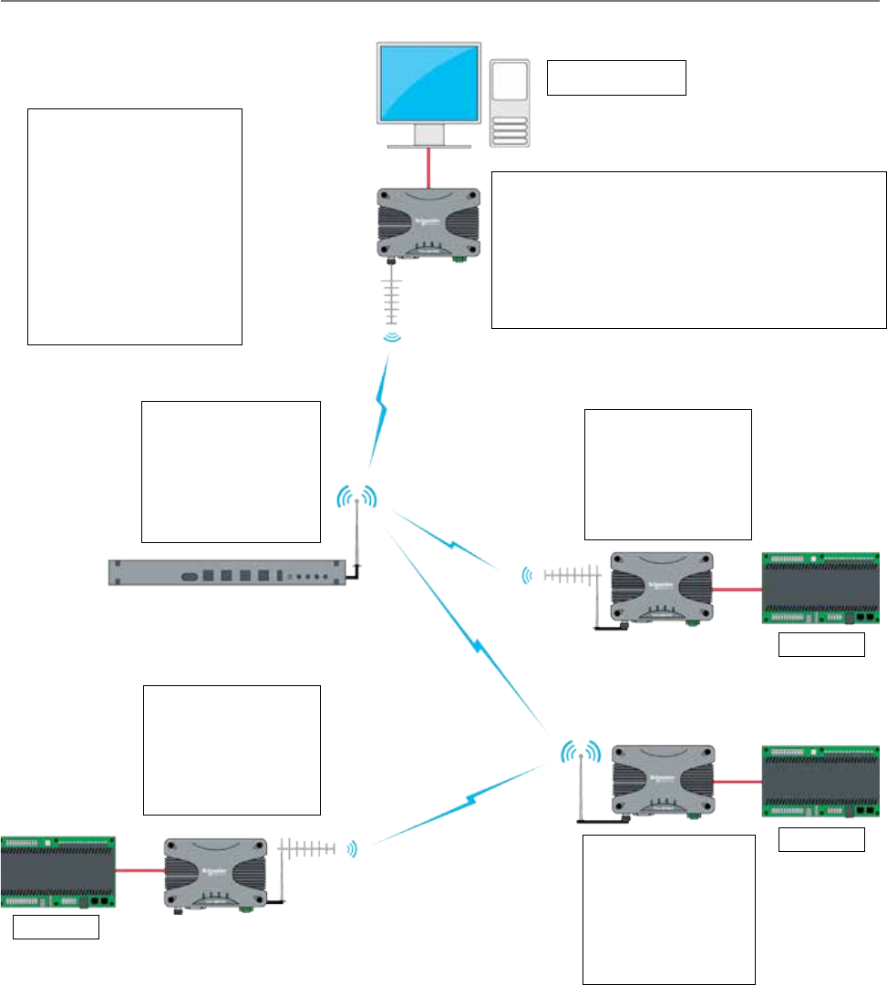
107
Document Number: 0100SM1401 Issue: 12-16
IP Routing - Serial Data PTMP via multiple Repeaters
Full Duplex Repeater
Network Settings:
IP: 192.168.2.1/24
Router Settings:
WAN IP: 10.10.10.2/24
Route Table Entries:
224.240.1.1 WAN WAN
192.168.1.0/24 10.10.10.1
Remote A
Network Settings:
IP: 192.168.3.1/24
Router Settings:
WAN IP: 10.10.10.3/24
Route Table Entries:
192.168.1.0/24 10.10.10.2
Serial Device
Half Duplex Repeater
Network Settings:
IP: 192.168.4.1/24
Router Settings:
WAN IP: 10.10.10.4/24
Route Table Entries:
224.240.1.1 WAN WAN
192.168.1.0/24 10.10.10.2
Remote B
Network Settings:
IP: 192.168.5.1/24
Router Settings:
WAN IP: 10.10.10.5/24
Route Table Entries:
192.168.1.0/24 10.10.10.4
Remote A, Half Duplex Repeater &
Remote B (Common)
COM1:
Mode: Serial Device Server
Character Layer: 9600,8,N,1
Interface: RS232.
Packet Layer: MODBUS
Protocol: UDP
Protocol Mode: Point to Multipoint
Node Type: Multi-Point
Remote IP Address: 192.168.1.1
Remote IP Port: 30010
Local Multicast IP: 224.240.1.1
Local IP Port: 30010
Host Application
Serial Data
Half Duplex Entry Point
Network Settings:
IP Address: 192.168.1.1/24
Router Settings:
WAN IP Address: 10.10.10.1/24
Route Table Entries:
224.240.1.1 LAN WAN
COM1:
Mode: Serial Device Server
Protocol: UDP
Protocol Mode: Point to Multipoint
Node Type: Point
Remote Multicast IP: 224.240.1.1
Remote IP Port: 30010
Local IP Port: 30010
Serial Device
Serial Device
This topology should use Carrier detect collision avoidance.
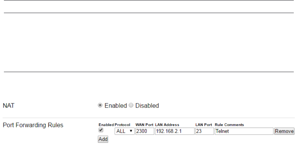
108 Document Number: 0100SM1401 Issue: 12-16
Network Address Translation (NAT)
NAT Configuration
NAT is only available when the radio is operating in IP Routing mode.
NAT configuration parameters can be accessed within the radio’s configuration page by browsing to: Setup -> IP Routing.
Introduction
As of firmware version 1.4.0, Network Address Translation (NAT) is available.
The following Diagrams are designed to provide configuration information on typical topologies. The channel bandwidth and
Tx/Rx frequencies are not shown within the diagrams, as they depend on the user’s license.
The following diagrams show ‘/24’ after an IP address. This short hand addressing indicates the device’s subnet mask. ‘/24’
equals a subnet mask of 255.255.255.0. Short hand addressing can be used when writing a static route.
Enable or disable the NAT feature via the Buttons shown above (Enable/Disable). When enabled Port Forwarding Rules
become available.
Port Forwarding Rules:
Rules for redirecting a Port on the WAN to a Port on the LAN at the specified LAN Address (250 Max).
• State: [Enable] or [Disable] the rule (1 or 0 in TUI)
• Protocol: Apply to [TCP], [UDP], or [ALL] traffic.
• WAN Port: Listening Port on the WAN interface.
• LAN Address: IP address to redirect traffic to.
• LAN Port: Port at the specified LAN Address to redirect traffic to.
• Rule Comments: Optional notes for the rule (128 Characters Max).
Part G – Quick Start Guide
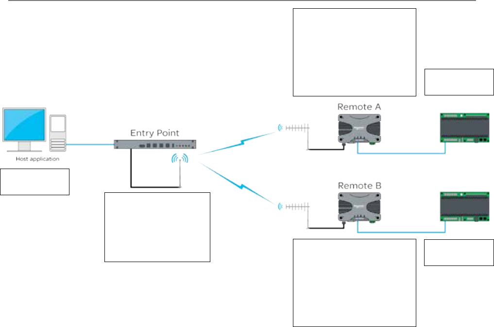
109
Document Number: 0100SM1401 Issue: 12-16
NAT - Point to Multipoint - Full Duplex Entry Point
Host Application
IP: 192.168.0.2/24
Gateway: 192.168.0.1
Remote A
Network Settings:
IP: 192.168.1.1/24
Router Settings:
WAN IP: 10.10.10.2/24
Route Table Entries:
192.168.0.0/24 10.10.10.1
Port Forwarding Rules
Enabled All 2300 192.168.1.2 23
Ethernet Device
IP: 192.168.1.2/24
Gateway: 192.168.1.1
Ethernet Device
IP: 192.168.1.2/24
Gateway: 192.168.1.1
The diagram above provides an example of how to port-forward a Telnet session. In order to establish a Telnet session
from the host application, to the Ethernet device connected to Remote A, the host application will have to use the following
addressing: [Telnet 10.10.10.2 2300]. This address references Remote A’s WAN IP and the unique port number allocated to
the Ethernet device specified within the port forwarding rule.
Entry Point
Network Settings:
IP: 192.168.0.1/24
Router Settings:
WAN IP: 10.10.10.1/24
NAT
Disabled
Part G – Quick Start Guide
Remote B
Network Settings:
IP: 192.168.1.1/24
Router Settings:
WAN IP: 10.10.10.3/24
Route Table Entries:
192.168.0.0/24 10.10.10.1
Port Forwarding Rules
Enabled All 2300 192.168.1.2 23
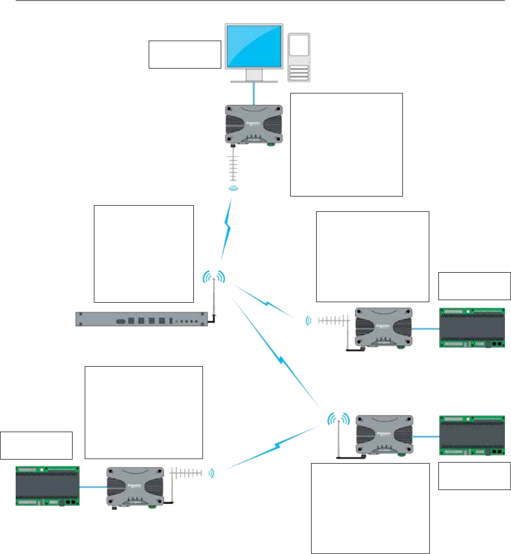
110 Document Number: 0100SM1401 Issue: 12-16
NAT - Point to Multipoint via multiple Repeaters
Host Application
IP: 192.168.0.2/24
Gateway: 192.168.0.1
Entry Point
Network Settings:
IP: 192.168.0.1/24
Router Settings:
WAN IP: 10.10.10.1/24
Route Table Entries:
10.10.10.3 10.10.10.2
10.10.10.4 10.10.10.2
10.10.10.5 10.10.10.2
NAT:
Disabled
Full Duplex Repeater
Network Settings:
IP: 192.168.1.1/24
Router Settings:
WAN IP: 10.10.10.2/24
Route Table Entries:
10.10.10.5 10.10.10.4
192.168.0.0/24 10.10.10.1
NAT:
Enabled
Remote A
Network Settings:
IP: 192.168.1.1/24
Router Settings:
WAN IP: 10.10.10.3/24
Route Table Entries:
192.168.0.0/24 10.10.10.2
Port Forwarding Rules
Enabled All 2300 192.168.1.2 23
Ethernet Device
IP: 192.168.1.2/24
Gateway: 192.168.1.1
Ethernet Device
IP: 192.168.1.2/24
Gateway: 192.168.1.1
Ethernet Device
IP: 192.168.1.2/24
Gateway: 192.168.1.1
Half Duplex Repeater
Network Settings:
IP: 192.168.1.1/24
Router Settings:
WAN IP: 10.10.10.4/24
Route Table Entries:
192.168.0.0/24 10.10.10.2
Port Forwarding Rules
Enabled All 2300 192.168.1.2 23
Remote B
Network Settings:
IP: 192.168.1.1/24
Router Settings:
WAN IP: 10.10.10.5/24
Route Table Entries:
192.168.0.0/24 10.10.10.4
Port Forwarding Rules
Enabled All 2300 192.168.1.2 23
The diagram above provides an example of how to port-forward a Telnet session from the Host application, to an Ethernet
device shown. In order to establish a Telnet session from the host application to the Ethernet device connected to Remote A,
the host application requires the following addressing: [Telnet 10.10.10.3 2300]. This address references Remote A’s WAN
IP and the unique port number allocated to the Ethernet device specified within the port forwarding rule.
Part G – Quick Start Guide
This topology should use Carrier detect collision avoidance.
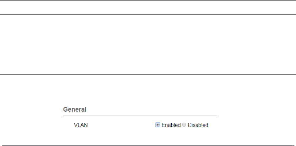
111
Document Number: 0100SM1401 Issue: 12-16
Virtual LAN (VLAN)
Introduction
As of firmware version 1.5.0, VLAN is available (in Transparent Bridge mode only).
VLAN can help provide isolation between separate entities who share a single network.
For example, Department A may require access to the radios configuration/Diagnostics, while Department B may only require
access to SCADA information. By implementing VLAN, a virtual network segregation can be implemented to help isolate each
of the departments from one another.
VLAN Configuration
To access the VLAN configuration section, browse to: Setup -> VLAN.
By default, VLAN is disabled. To enable VLAN, select ‘Enabled’. The configurable range of each VLAN is 1 - 4094.
Radio Services VLAN
Management VLAN ID:
Defines the VLAN ID for access to radio management services. Management services include HTTP/S, Telnet, SSH, SNMP
and eDiags. A minimum of one Ethernet interface must be a member of this VLAN to ensure that radio management
services can be accessed. (Default = 1).
SCADA VLAN:
Enables a separate VLAN for radio SCADA services. SCADA services include serial device server & MODBUS gateway. Allows
external serial devices to be connected to COM1/2 and belong to a separate SCADA VLAN. Once enabled, additional
configuration options become available:
- SCADA VLAN ID: SCADA VLAN ID is normally the same VLAN ID defined for SCADA traffic on the Ethernet interface.
Default value is 2.
- SCADA VLAN IP Address: Defines the unique IP address for the Serial Device Server/MODBUS Gateway when they
belong to the SCADA VLAN.
- SCADA VLAN Subnet Mask: Defines the subnet mask for the SCADA VLAN. This determines which IP addresses are
local to the device, and which should be reached through a gateway or router
- COM1 VLAN: Defines the VLAN that the serial device server/MODBUS Gateway using COM1 belongs to. (If SCADA
VLAN is disabled, this defaults to Management)
Management: Service on serial port COM1 will be assigned to the management VLAN
SCADA: Service on serial port COM1 will be assigned to the SCADA VLAN.
- COM2 VLAN: Defines the VLAN that the serial device server/MODBUS Gateway using COM2 belongs to. (If SCADA
VLAN is disabled, this defaults to Management)
Management: Service on serial port COM2 will be assigned to the management VLAN.
SCADA: Service on serial port COM2 will be assigned to the SCADA VLAN.
Part G – Quick Start Guide

112 Document Number: 0100SM1401 Issue: 12-16
Ethernet Ports (VLAN)
Each Ethernet port can be independently configured to operate in one of two modes: Access or Trunk.
Access: a port in access mode will process un-tagged packets from the Ethernet interface, append the corresponding Port
VLAN ID (PVID) and send the packets over the radio channel. When a packet is received on the radio channel, the packet’s
VLAN tag will be examined, and if it matches the user configured PVID for any Ethernet port on the radio, the tag will be
removed and sent out the corresponding port.
A port configured in access mode, requires a Port VLAN ID (PVID).
Access ports configured with a PVID which match the management services VLAN will provide access to internal radio
management services.
Trunk: a port in trunk mode will transmit tagged VLAN packets from the Ethernet interface over the radio channel. If an un-
tagged packed is received on the port, it will be discarded.
Filtering can be applied to a trunk port, to allow only select VLAN IDs to pass through the port.
Ingress Filtering, when enabled, applies filtering on VLAN packets processed on any Ethernet port configured as a trunk port.
The filter will discard all VLAN tagged packets which are not found within the membership table (for the corresponding port)
while, allowing VLAN tagged packets within the membership table to be sent over the radio channel. When Disabled, the
Ethernet interface will pass all tagged VLAN packets over the radio channel.
Membership
VLAN Membership:
For trunked ports with ingress filtering enabled, VLAN IDs not defined in the table are discarded.
• State: [Enable] or [Disable] the VLAN
• VID: VLAN ID (1-4094).
• ETH1: Include ETH1 in this VLAN. Can not be enabled if ETH1 is an access port.
• ETH2: Include ETH2 in this VLAN. Can not be enabled if ETH2 is an access port.
• Description: Description of the VLAN (128 Characters Max).
Part G – Quick Start Guide
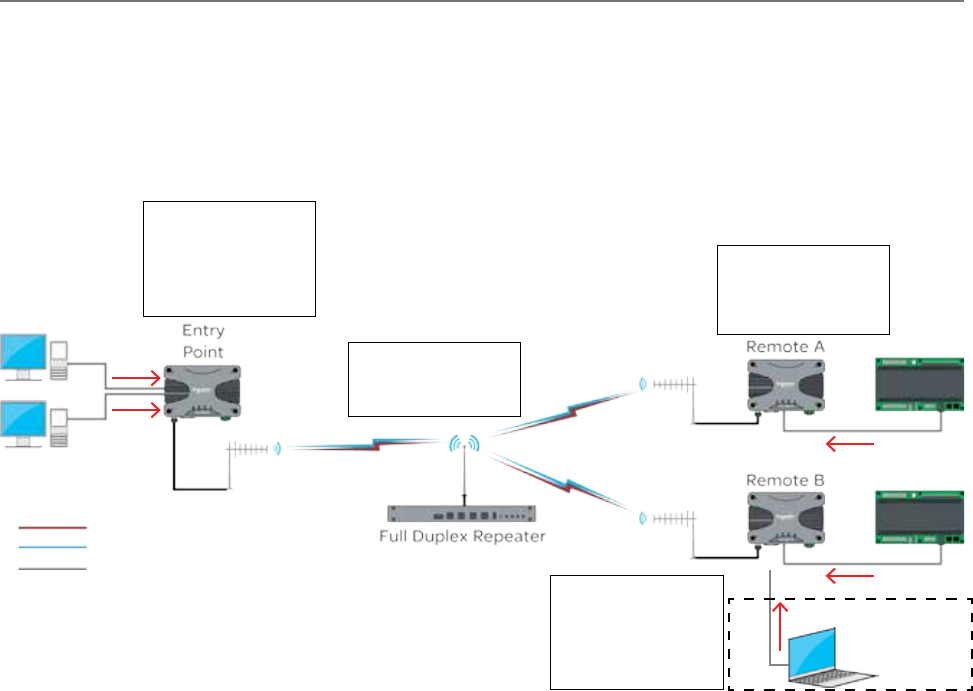
113
Document Number: 0100SM1401 Issue: 12-16
VLAN - PTMP via Repeater
The following Diagrams are designed to provide VLAN configuration information on typical topologies. The channel bandwidth
and Tx/Rx frequencies are not shown within the diagrams, as they depend on the user’s license.
The following examples require a prerequisite understanding of VLAN functionality.
Example 1: Access Port
The following example shows the configuration of VLAN required to isolate different hosts residing on the same network.
Part G – Quick Start Guide
[VLAN 1] Network Management
[VLAN 2] SCADA Control
Un-Tagged packets
Entry Point configuration
VLAN:
Management VLAN ID: 1
ETH1 Mode: Access
ETH1 PVID: 1
ETH2 Mode: Access
ETH2 PVID: 2
ETH1
ETH2
Network
Management
SCADA
Control
ETH2
ETH2
The Network Management Host is connected to the ETH1 interface of the Entry Point radio. Via this interface, the Network
Management Host will reside on VLAN 1 (over the radio network). As the Management VLAN ID of each radio is a member of
VLAN 1, the Network Management Host will have access to radio services including: HTTP/S, Telnet, SSH, SNMP & eDiags.
The SCADA Control Host is connected to the ETH2 interface of the Entry Point radio. Via this interface, the SCADA Control
Host will reside on VLAN 2 (over the radio network). As the remote radio’s ETH2 interface is a member of VLAN 2, the SCADA
Control Host will have access to the SCADA devices connected to the ETH2 interface of the remote radios.
In this example, the Network Management Host does not have access to the SCADA devices (as they are connected to the
ETH2 interface of the remote radios, which is a member of VLAN 2), while the SCADA Control Host does not have access to
radio services, as they reside on VLAN 1.
ETH1 Optional connection for
radio system diagnostics
Full Duplex Repeater
configuration
VLAN:
Management VLAN ID: 1
Remote A configuration
VLAN:
Management VLAN ID: 1
ETH2 Mode: Access
ETH2 PVID: 2
Remote B configuration
VLAN:
Management VLAN ID: 1
ETH1 Mode: Access
ETH1 PVID: 1
ETH2 Mode: Access
ETH2 PVID: 2
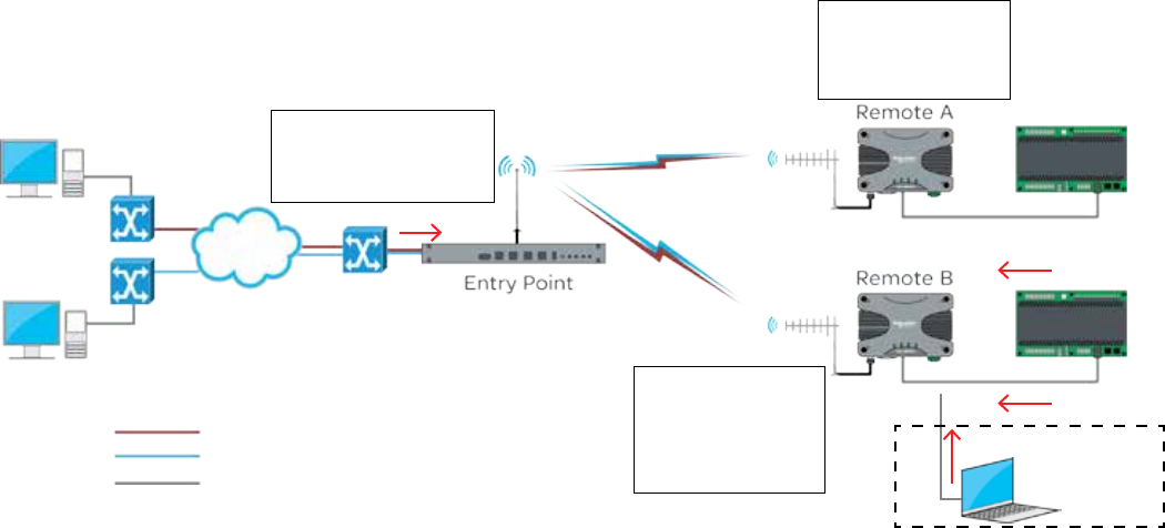
114 Document Number: 0100SM1401 Issue: 06-16
Example 2: Trunk Port
The following example shows the configuration of VLAN required to allow pre-tagged VLAN packets, to be sent over the radio network.
Part G – Quick Start Guide
[VLAN 1] Network Management
[VLAN 2] SCADA Control
Un-Tagged packets
ETH1
Network
Management
SCADA
Control
ETH2
ETH2
Ethernet
Switch
WAN
Ethernet
Switch
Entry Point VLAN configuration
VLAN:
Management VLAN ID: 1
ETH1 Mode: Trunk
ETH1 Ingress Filtering: Disabled
ETH1 Optional connection for
radio system diagnostics
Pre-tagged VLAN packets are sent into each port of the entry point radio. This example shows managed Ethernet switches
performing the VLAN tagging.
The entry point radio is configured to trunk VLAN 1 & VLAN 2 on the ETH1 interface.
As packets from the Network Management Host are being tagged on VLAN 1 (by the managed switch) and the Management
VLAN ID of each radio is a member of VLAN 1, the Network Management Host will have access to radio services including:
HTTP/S, Telnet, SSH, SNMP & eDiags.
As packets from the SCADA Control Host are being tagged on VLAN 2 (by the managed switch) and the remote radio’s ETH2
interface is a member of VLAN 2, the SCADA Control Host will have access to the SCADA devices connected to the ETH2
interface of the remote radios.
In this example, the Network Management Host does not have access to the SCADA devices (as they are connected to the
ETH2 interface of the remote radios, which is a member of VLAN 2), while the SCADA Control Host does not have access to
radio services, as the managed switch has tagged them on VLAN 1.
Example 3: Trunk Port & Access Port
A mixture of the preceding examples can be implemented on the radio network. In this circumstance, the trunk port will not
allow the VLAN which the Access port is a member of, unless specified in the membership table.
Remote A configuration
VLAN:
Management VLAN ID: 1
ETH2 Mode: Access
ETH2 PVID: 2
Remote B configuration
VLAN:
Management VLAN ID: 1
ETH1 Mode: Access
ETH1 PVID: 1
ETH2 Mode: Access
ETH2 PVID: 2
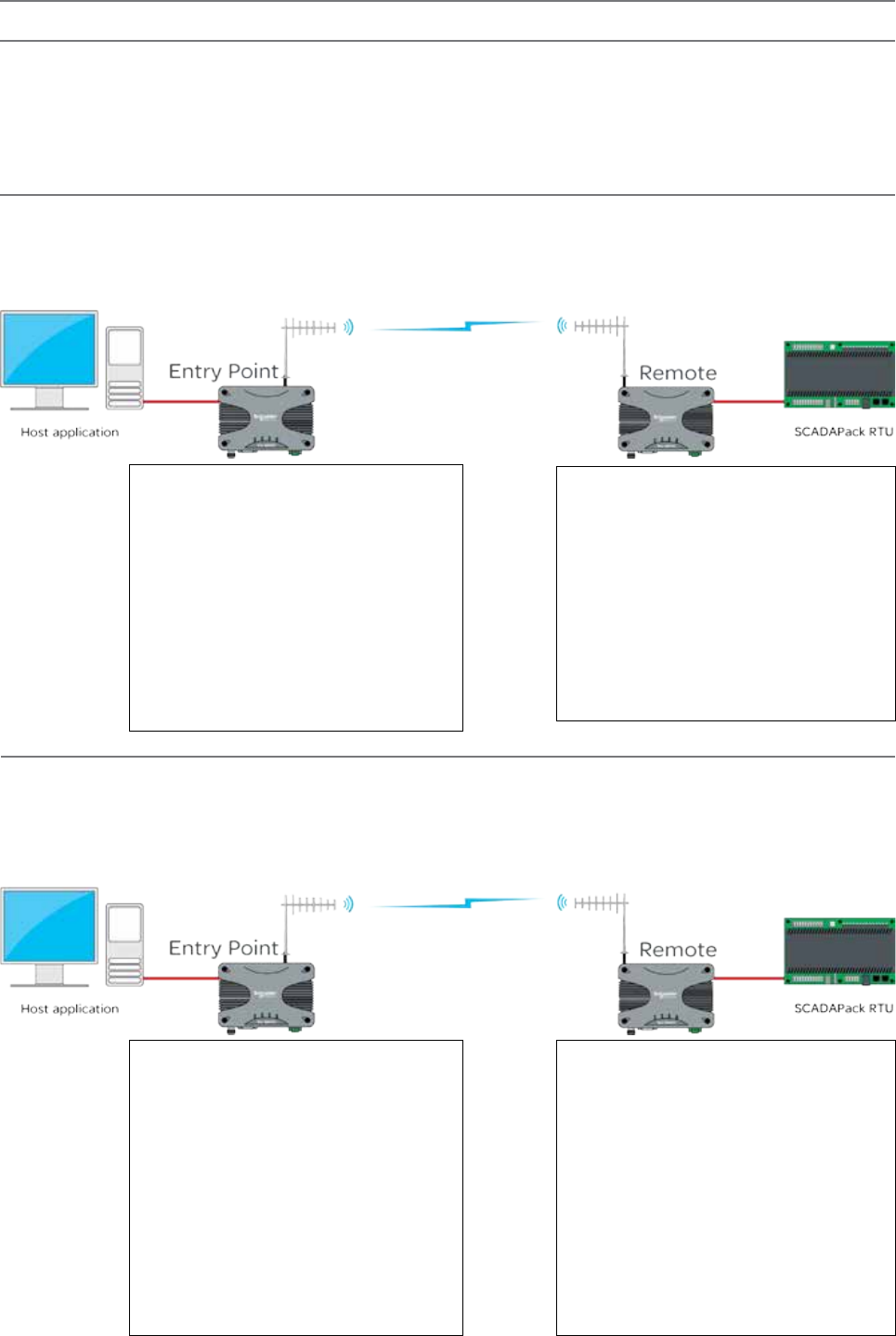
115
Document Number: 0100SM1401 Issue: 06-16
Serial and MODBUS
Serial data transport via TCP
Connect the PC’s Ethernet port to ETH1 or ETH2 of the radio being configured and using a web browser, browse to the
radio’s configuration page by entering the IP address the unit into the browser’s URL bar. Once the configuration has been
activated, repeat the process for the remaining radio.
To access the parameters below, browse to the “Setup” tab and select the “COM1” option under “Configuration”.
Remote - 192.168.2.17
COM1:
Mode: Serial Device Server
Character Layer and interface: match the
configuration of the external serial device you are
connecting to the Q data radios Serial Port. The
default is 9600,8,N,1 - RS232.
Packet Layer: MODBUS
Protocol: TCP
Protocol Mode: TCP Client
Primary IP Address: 192.168.2.16
Primary IP Port: 30010
Entry Point - 192.168.2.16
COM1:
Mode: Serial Device Server
Character Layer and Interface: match the
configuration of the external serial device you
are connecting to the Q data radio’s Serial Port.
The default is 9600,8,N,1 - RS232.
Packet Layer: MODBUS
Protocol: TCP
Protocol Mode: TCP Server
Local IP Port: 30010
Inactivity Timeout: 30 seconds.
Serial data transport via UDP
Connect the PC’s Ethernet port to ETH1 or ETH2 of the radio being configured and using a web browser, browse to the
radio’s configuration page by entering the IP address the unit into the browser’s URL bar. Once the configuration has been
activated, repeat the process for the remaining radio.
To access the parameters below, browse to the “Setup” tab and select the “COM1” option under “Configuration”.
Remote - 192.168.2.17
COM1:
Mode: Serial Device Server
Character Layer and interface: match the
configuration of the external serial device you are
connecting to the Q data radios Serial Port. The
default is 9600,8,N,1 - RS232.
Packet Layer: MODBUS
Protocol: UDP
Protocol Mode: Point to point
UDP listen mode: static
Remote IP Address: 192.168.2.16
Remote IP Port: 30010
Local IP Port: 30010
Entry Point - 192.168.2.16
COM1:
Mode: Serial Device Server
Character Layer and Interface: match the
configuration of the external serial device you
are connecting to the Q data radio’s Serial Port.
The default is 9600,8,N,1 - RS232.
Packet Layer: MODBUS
Protocol: UDP
Protocol Mode: Point to point
UDP listen mode: static
Remote IP Address: 192.168.2.17
Remote IP Port: 30010
Local IP Port: 30010
Introduction
Point to Point serial connectivity can be achieved by using the serial device server embedded within the Q data radios radio. The serial
device server has three protocols available, each with their own benefits:
TCP: Establishes a session based connection, providing high reliability on data delivery.
UDP: Consumes low bandwidth and provides a low latency connection.
PPP: Provides a virtual Ethernet connection over a serial link.
Part G – Quick Start Guide
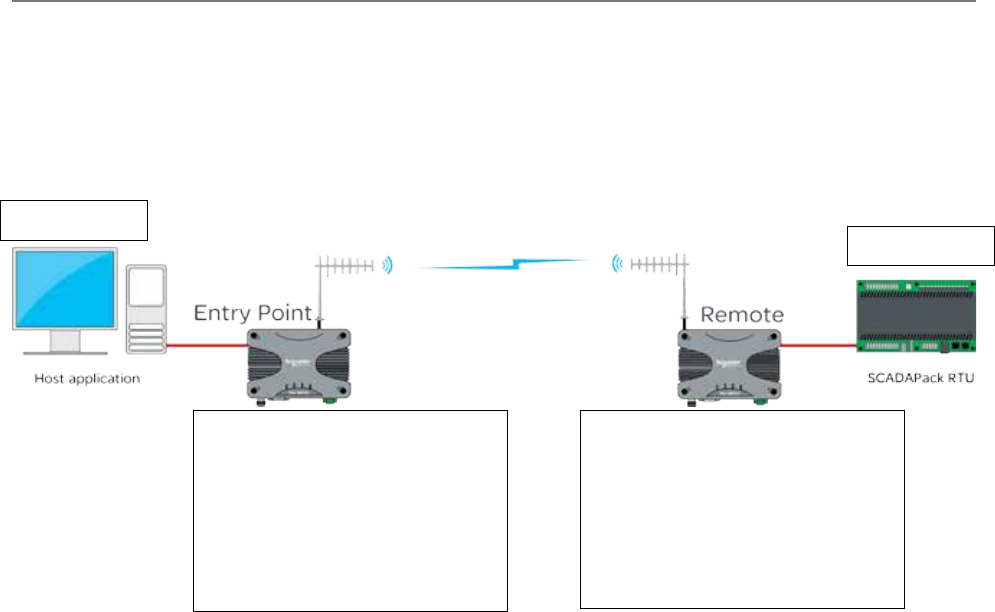
116 Document Number: 0100SM1401 Issue: 12-16
Serial data transport via PPP
Connect the PC’s Ethernet port to ETH1 or ETH2 of the radio being configured and using a web browser, browse to the
radio’s configuration page by entering the IP address the unit into the browser’s URL bar. Once the configuration has been
activated, repeat the process for the remaining radio.
To access the parameters below, browse to the “Setup” tab and select the “COM1” option under “Configuration”.
The example uses the following IP addresses for external PPP Clients: ‘Host Application - 192.168.2.20’ ‘External Device
(RTU) - 192.168.2.30’
Host Application
IP: 192.168.2.20 External Device
IP: 192.168.2.30
Remote - 192.168.2.17
COM1:
Mode: Serial Device Server
Baud Rate: match the Baud Rate of the
external serial device you are connecting to
the Q data radios Serial Port.
Protocol: PPP
Client IP Address: 192.168.2.30
Entry Point - 192.168.2.16
COM1:
Mode: Serial Device Server
Baud Rate: match the Baud Rate of the
external serial device you are connecting
to the Q data radios Serial Port.
Protocol: PPP
Client IP Address: 192.168.2.20
Part G – Quick Start Guide
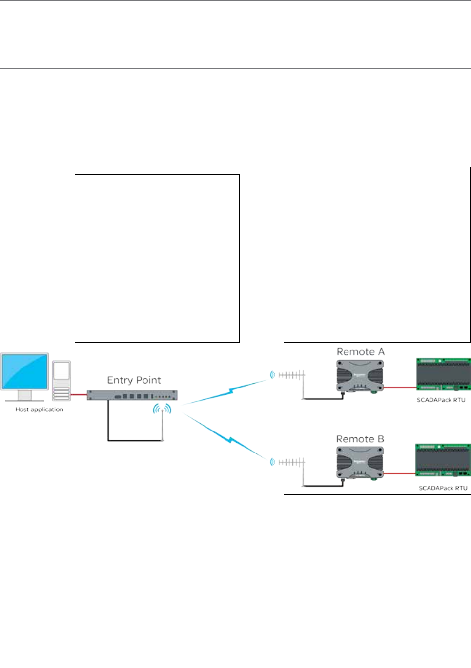
117
Document Number: 0100SM1401 Issue: 12-16
Point to Multipoint Serial to Serial Link Setup
Introduction
Point to Multipoint serial connectivity can be achieved by using the serial device server embedded within the Q data radios. The serial
device server can be used in UDP mode, to achieve a point to multipoint serial link.
Serial data transport via UDP
Connect the PC’s Ethernet port to ETH1 or ETH2 of the radio being configured and using a web browser, browse to the
radio’s configuration page by entering the IP address the unit into the browser’s URL bar. Once the configuration has been
activated, repeat the process for the remaining radio/s.
To access the parameters below, browse to the “Setup” tab and select the “COM1” option under “Configuration”.
The allocated IP addresses for this example are ‘Entry Point- 192.168.2.16’, ‘Remote A - 192.168.2.17’, ‘Remote B -
192.168.2.18’.... (additional remotes can use incremental IP allocation from Remote B).
Entry Point - 192.168.2.16
COM1:
Mode: Serial Device Server
Character Layer and Interface: match the
configuration of the external serial device you
are connecting to the Q data radios Serial
Port. The default is 9600,8,N,1 - RS232.
Packet Layer: MODBUS
Protocol: UDP
Protocol Mode: Point to Multipoint
Node Type: Point
Remote Multicast IP Address: 224.240.1.1
Remote IP Port: 30010
Local IP Port: 30010
Remote A - 192.168.2.17
COM1:
Mode: Serial Device Server
Character Layer and interface: match the
configuration of the external serial device you are
connecting to the Q data radios Serial Port. The
default is 9600,8,N,1 - RS232.
Packet Layer: MODBUS
Protocol: UDP
Protocol Mode: Point to Multipoint
Node Type: Multi-Point
Remote IP Address: 192.168.2.16
Remote IP Port: 30010
Local Multicast IP Address: 224.240.1.1
Local IP Port: 30010
Remote B - 192.168.2.18
COM1:
Mode: Serial Device Server
Character Layer and interface: match the
configuration of the external serial device you are
connecting to the Q data radios Serial Port. The
default is 9600,8,N,1 - RS232.
Packet Layer: MODBUS
Protocol: UDP
Protocol Mode: Point to Multipoint
Node Type: Multi-Point
Remote IP Address: 192.168.2.16
Remote IP Port: 30010
Local Multicast IP Address: 224.240.1.1
Local IP Port: 30010
Part G – Quick Start Guide
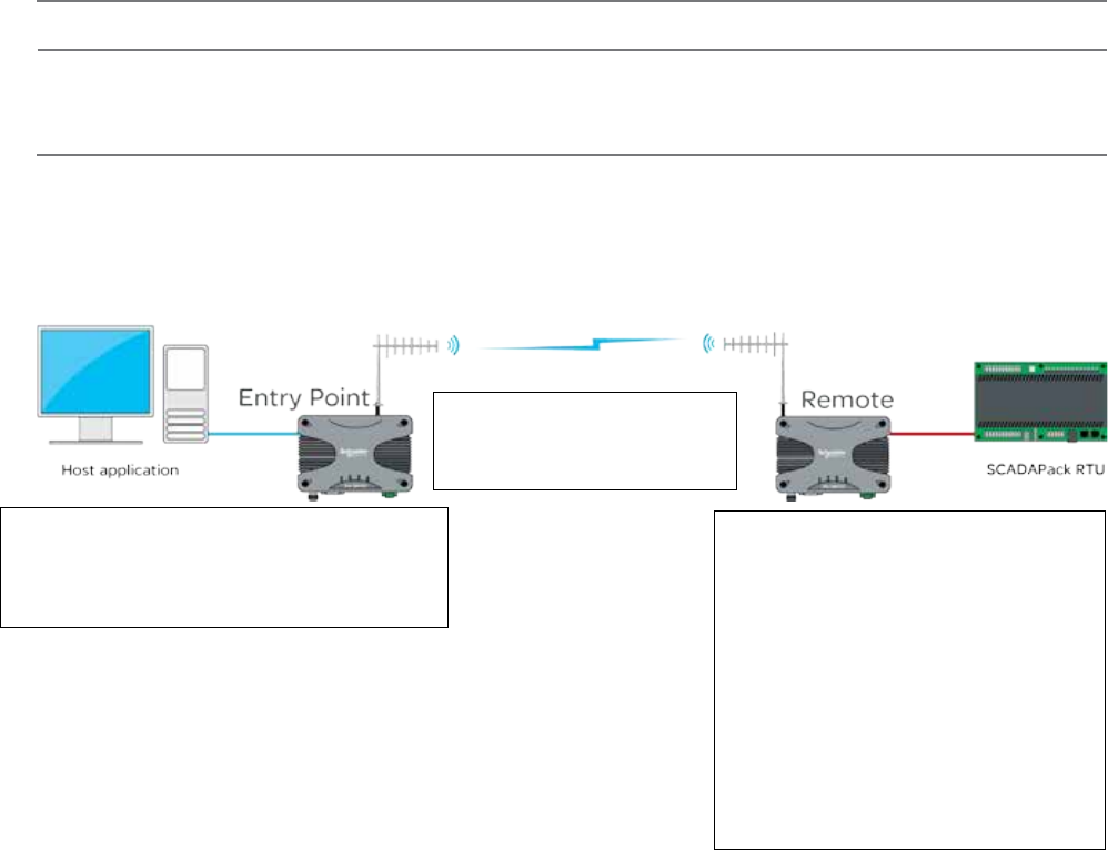
118 Document Number: 0100SM1401 Issue: 12-16
MODBUS Gateway
MODBUS TCP to MODBUS RTU - Point to point
Connect the PC’s Ethernet port to ETH1 or ETH2 of the radio being configured and using a web browser, browse to the
radio’s configuration page by entering the IP address the unit into the browser’s URL bar. Once the configuration has been
activated, repeat the process for the remaining radio/s.
To access the parameters below, browse to the “Setup” tab and select the “COM1” option under “Configuration”.
Introduction
Point-to-Point (PTP) with MODBUS TCP to MODBUS RTU can be performed by using the MODBUS gateway feature
embedded within the Q data radios.
Remote - 192.168.2.17
COM1:
Mode: MODBUS/TCP Gateway
Character Layer and Interface: match the
configuration of the external serial device you
are connecting to the Q data radio’s Serial Port.
The default is 9600,8,N,1 - RS232.
Packet Layer: MODBUS
Protocol: TCP
Protocol Mode: TCP Server
Local IP Port: 30010
Inactivity Timeout: 30 seconds
MODBUS RTU Timeout: 10 seconds
Entry Point - 192.168.2.16
(In this topology, the entry point radio is
transparent to the MODBUS TCP data).
No COM port configuration is required.
Part G – Quick Start Guide
Host Application - 192.168.2.10
Port number: 30010
Protocol: MODBUS/TCP
SCADApack RTU Destination Address: 192.168.2.17
SCADApack RTU Destination Port number: 30010
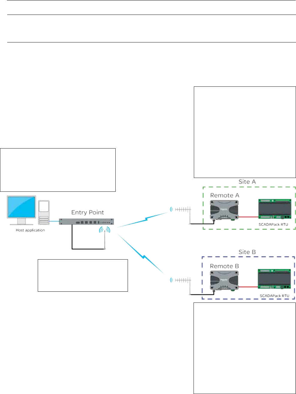
119
Document Number: 0100SM1401 Issue: 12-16
Introduction
Point to multipoint (PTMP) with MODBUS TCP to MODBUS RTU can be performed by using the MODBUS gateway feature
embedded within the Q data radios.
MODBUS TCP to MODBUS RTU - Point to multipoint
MODBUS TCP to MODBUS RTU - Point to multipoint
Connect the PC’s Ethernet port to ETH1 or ETH2 of the radio being configured and using a web browser, browse to the
radio’s configuration page by entering the IP address the unit into the browser’s URL bar. Once the configuration has been
activated, repeat the process for the remaining radio/s.
To access the parameters below, browse to the “Setup” tab and select the “COM1” option under “Configuration”.
Host Application - 192.168.2.10
Port number: 30010
Protocol: MODBUS/TCP
Site A - RTU Destination Address: 192.168.2.17
Site A - RTU Destination Port number: 30010
Site B - RTU Destination Address: 192.168.2.18
Site B - RTU Destination Port number: 30010
Entry Point - 192.168.2.16
(In this topology, the entry point radio is
transparent to the MODBUS TCP data).
No COM port configuration is required.
Remote A - 192.168.2.17
COM1:
Mode: MODBUS/TCP Gateway
Character Layer and Interface: match the
configuration of the external serial device you
are connecting to the Q data radio’s Serial
Port. The default is 9600,8,N,1 - RS232.
Packet Layer: MODBUS
Protocol: TCP
Protocol Mode: TCP Server
Local IP Port: 30010
Inactivity Timeout: 30 seconds.
MODBUS RTU Timeout: 10 seconds
Remote B - 192.168.2.18
COM1:
Mode: MODBUS/TCP Gateway
Character Layer and Interface: match the
configuration of the external serial device you
are connecting to the Q data radio’s Serial
Port. The default is 9600,8,N,1 - RS232.
Packet Layer: MODBUS
Protocol: TCP
Protocol Mode: TCP Server
Local IP Port: 30010
Inactivity Timeout: 30 seconds.
MODBUS RTU Timeout: 10 seconds
Part G – Quick Start Guide
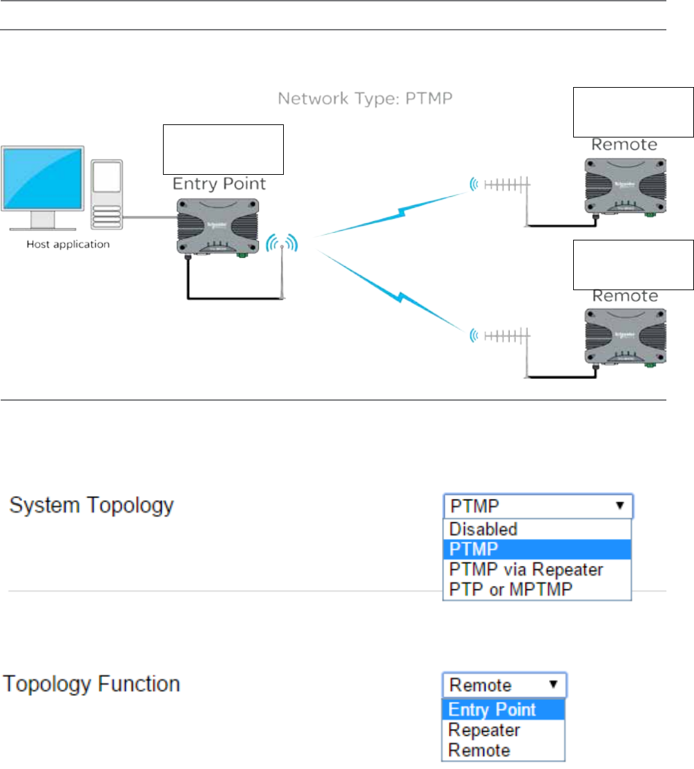
120 Document Number: 0100SM1401 Issue: 12-16
Single Frequency (Simplex) Mode
Introduction
Half Duplex Trio Q data radios can operate in a single frequency (Simplex) mode. This means the transmitting and receiving
frequencies are the same single frequency. See the diagram below. (The frequencies shown are for example purposes only).
Radio Frequencies:
Tx = 450 MHz
Rx = 450 MHz
Radio Frequencies:
Tx = 450 MHz
Rx = 450 MHz
Radio Frequencies:
Tx = 450 MHz
Rx = 450 MHz
Configuration
Single frequency operation also requires parameters to be configured which relate to the system topology.
System Topology: Select between Point to Multipoint (PTMP), Point to Multipoint via Repeater (PTMP via Repeater) or Point to
Point (PTP). Every radio in a simplex radio system should have same system topology selected.
Topology Function: Each radio in a simplex radio system will have its own topology function. Select between Entry Point,
Repeater or Remote.
Part G – Quick Start Guide
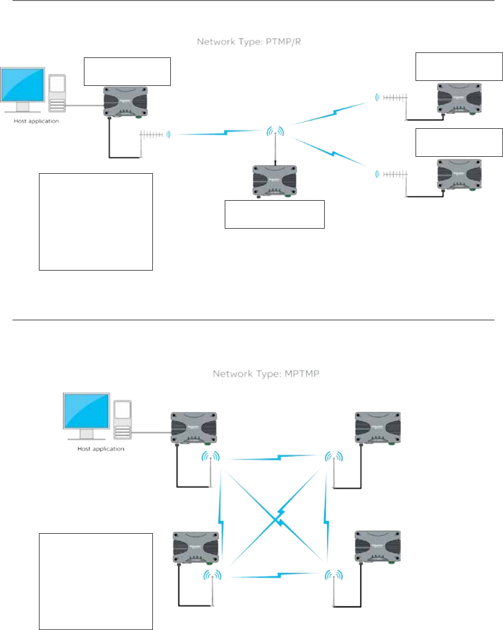
121
Document Number: 0100SM1401 Issue: 12-16
Simplex PTMP via Repeater
Point to multipoint via repeater(PTMP/R) in simplex mode can be performed. See the diagram below for an example:
Common Simplex
Configuration Parameters:
Radio Frequencies:
Tx = 450 MHz
Rx = 450 MHz
System Topology:
PTMP via Repeater
Topology Function:
Entry Point
Topology Function:
Repeater
Topology Function:
Remote
Topology Function:
Remote
Simplex MPTMP
Multipoint to multipoint in simplex mode can be performed. See the diagram below for an example:
Common Simplex
Configuration Parameters:
Radio Frequencies:
Tx = 450 MHz
Rx = 450 MHz
System Topology:
PTP or MPTMP
Part G – Quick Start Guide
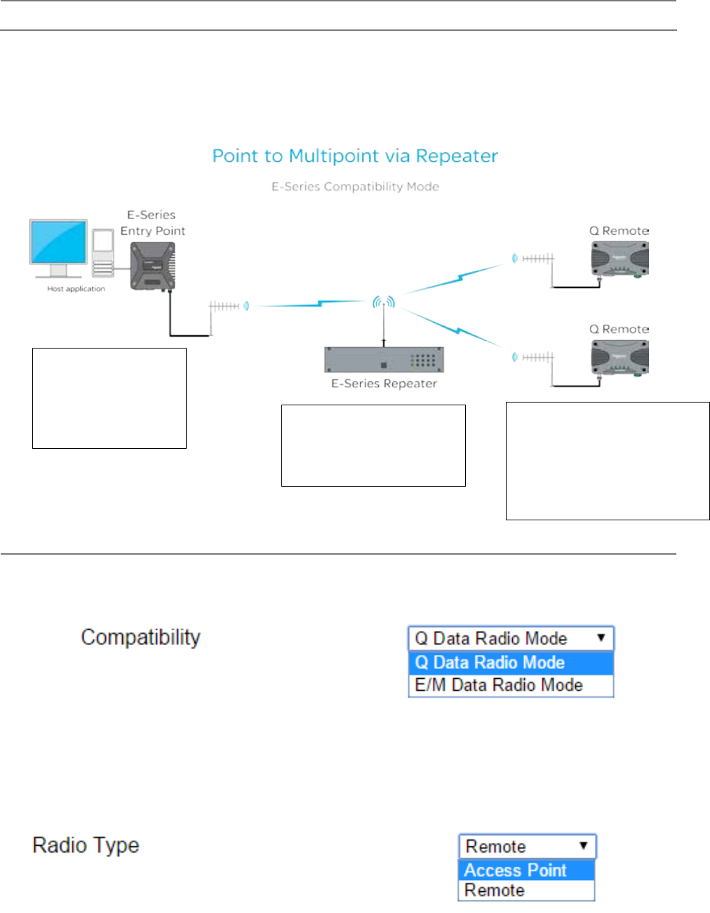
122 Document Number: 0100SM1401 Issue: 12-16
E-Series Emulation Mode
Part G – Quick Start Guide
Introduction
As of firmware release 1.3.6.3674, the Q (UHF only) supports E-Series emulation mode. The Diagram below shows a
typical E-Series PTMP via Repeater topology, where the remote sites have been replaced with half duplex Q data radios.
Configuration values which are fundamental to a successful radio link are shown below to provide an example on how to
configure the Q data radios in E-Series emulation mode. Single frequency or two frequency systems can utilise E-Series
emulation mode.
Modulation: 9600 12.5KHz
Radio Type: Remote
Collision Avoidance: Digital
Ethernet SID: 250
Serial Rx SID: 2
Serial Tx SID: 3
Modulation: 9600 12.5KHz
Radio Type: Access Point
Collision Avoidance: Digital Master
Peer to Peer: Enabled
SID Repeat Range: 2-3
Modulation: E-Series Emulation Mode
Type: 9600 12.5KHz
Radio Type: Remote
Collision Avoidance: Digital
Ethernet SID: 250
Serial Rx SID: 3
Serial Tx SID: 2
Configuration
The configuration parameters shown in the diagram above can be accessed within the Q data radio within the following locations:
Modulation (Setup -> Radio -> Modulation) provides the compatibility options of: Q Data Radio Mode or E/M Data Radio Mode.
Radio Type (Setup -> Radio -> System Parameters) provides the options of:
- Access Point
- Remote
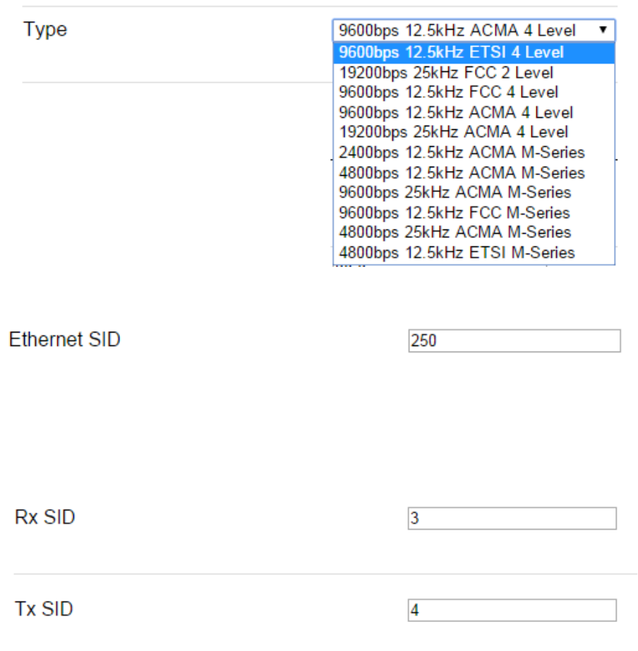
123
Document Number: 0100SM1401 Issue: 12-16
Ethernet Stream ID (SID) (Setup -> Radio -> System Parameters) provides the configuration option of Ethernet SID to be used
Serial Rx/Tx SIDs (Setup -> Serial COM 1 (or 2) provides the configuration options of the Serial SIDs to be used
Radio configuration is still performed via WUI or TUI (not via TView+ Programmer).
For detailed information on E-Series parameters, refer to the E-Series user manual.
Part G – Quick Start Guide
Type (Setup -> Radio -> Modulation) the following bandwidth/data rates are supported. Availability is dependant on the
regional approval of the radio (ACMA/ETSI/FCC):
• E-Series
9600 12.5 kHz ACA 4 Level
19200 25.0 kHz ACA 4 Level
9600 12.5 kHz FCC 4 Level
19200 12.5 kHz FCC 4 Level
19200 25.0 kHz FCC 2 Level
9600 12.5 kHz ETSI 4 Level
For BER specifications and/or sensitivities, refer to the corresponding E or M Series Data sheet.
• M-Series
9600 25.0kHz ACA M-Series
4800 12.5kHz ACA M-Series
4800 25.0kHz ACA M-Series
2400 12.5kHz ACA M-Series
9600 12.5kHz FCC M-Series
4800 12.5kHz ETSI M-Series
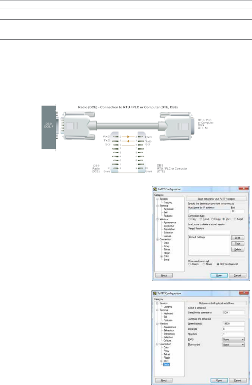
124 Document Number: 0100SM1401 Issue: 12-16
Part H – Advanced
Part H – Advanced
Connectivity
Text User Interface (TUI)
The Text user interface can be accessed via; a serial connection, a Telnet session or a SSH session.
TUI Interface - Serial Console
The serial TUI interface is accessed via the COM 1/2 interface as shown in the diagram below. By default, the TUI can be
accessed via COM 1 (Pins 2,3 & 5) .
Text User Interface:
• Com 1
• Port Speed : 19200 bps
• Format : 8, N, 1
Connection to the PC requires a strait-through serial cable with Pins 2,3 & 5 connected. Hardware handshaking is not
enabled by default within the Q data radios, so unless handshaking is a requirement, no other connections are required.
Once the Q data radio is connected to the PC via a strait through
serial cable, use a serial console tool to create a serial communications
connection to the TUI. The following example uses a software package
called ‘PuTTY’. PuTTY is a freely available Serial console, SSH and Telnet
client. PuTTY can be downloaded from: http://www.putty.org/
Once installed, open PuTTy to display the configuration window.
Within the ‘Category’ section, go to: Connection > Serial. Within the serial
line configuration section configure the serial port you will be using to
interface to the Q data radio to the following settings:
• Speed (baud): 19200
• Data bits: 8
• Stop bits: 1
• Parity: None
• Flow control: None
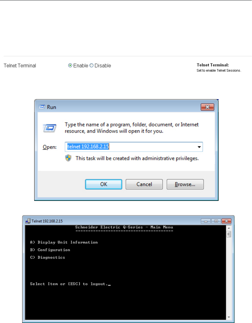
125
Document Number: 0100SM1401 Issue: 12-16
If security password protection has been enabled, you will first need to enter the appropriate user name and password.
If the Telnet connection was successful, the following screen will be displayed.
To start a Telnet session, open a command window via “Start -> Run” and type “Telnet xxx.xxx.xxx.xxx” where xxx is the IP
address of the target radio. See example below.
TUI Interface - Telnet session
The text user interface can be accessed via Telnet. This is convenient if you are remotely connected to a Q data radio via an
Ethernet network. The Telnet interface requires much less bandwidth compared to the web user interface, which results in
higher speed access to configuration parameters and diagnostics. Most computer operating systems come with integrated
Telnet software. For Windows based operating system, you can initiate a Telnet session using the command line interface.
Before you can connect to the text user interface (TUI) via Telnet, ensure that the Telnet interface within the Q data radio is
enabled. By default, the Telnet service is enabled. The Telnet service can be enabled/disabled using the Web user interface.
Enable the interface via the “Configuration -> Security” menu item as shown below.
Part H – Advanced
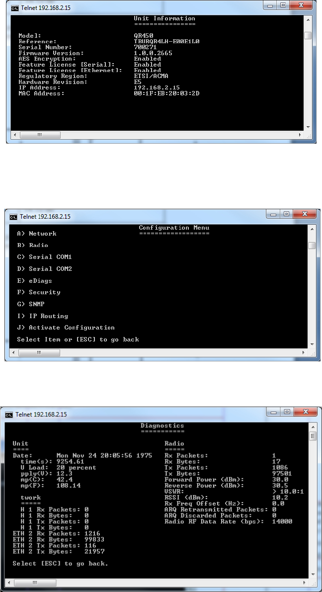
126 Document Number: 0100SM1401 Issue: 12-16
(2) Configuration - Provides access to the configuration of Network Parameters, Radio configuration, Serial interfaces, eDiags,
Security, SNMP and IP routing.
The TUI is divided into three distinct areas :
(1) Unit Information - Displays unique unit information about the radio such as serial number, currently configured IP address
and firmware pack version identification.
(3) Diagnostics - Provides access to the Diagnostics facilities in the radio.
Part H – Advanced
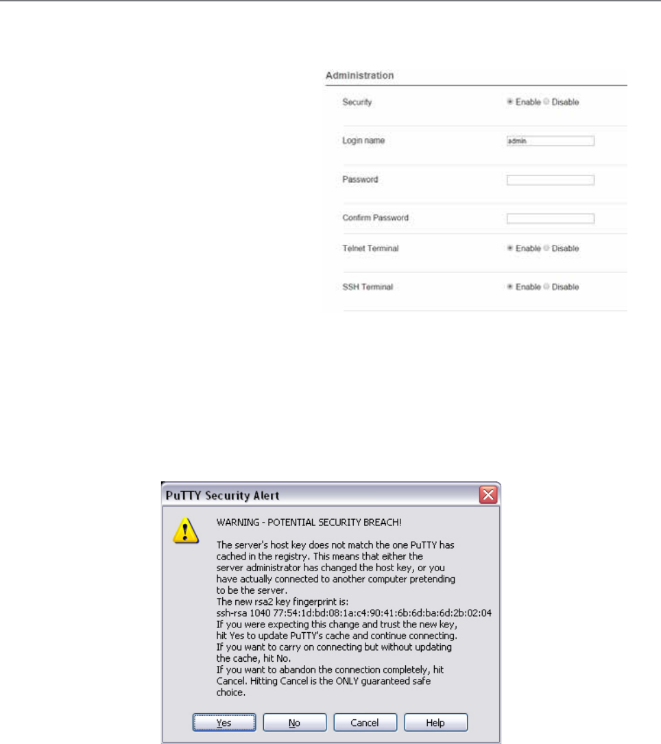
127
Document Number: 0100SM1401 Issue: 12-16
The client will take the following process to authenticate the server:
• The client requests the device finger print from the server it is trying to connect to.
• Once the client has received the server’s finger print, it will check it’s own records to see whether it already has this
finger print in memory.
• If it does have the finger print on record, the connection between the client and the server should automatically begin.
• If the client does not have the finger print in memory, a security alert will appear, advising the user that either an
attacker could be an intercepting the device as it does not have the finger print on record, or it is a new device that it
has not connected to before.
Secure Shell (SSH)
Secure Shell (SSH) provides a secure alternative to standard Telnet. To access the Q data radio’s Text User Interface (TUI)
via the embedded SSH server, use an SSH client. The following example shows how to access a Q data radio’s TUI using a
commonly used Windows SSH client called PuTTY.
Before you can connect to the TUI via SSH, ensure that
the SSH server within the Q data radio is enabled (set
to SSH Terminal to Enable). For security reasons, the
SSH server is disabled by default. It can be enabled
via the web user interface. Enable the interface via the
“Configuration -> Security” menu item as shown.
Upon enabling SSH, you will also be required to fill out
a user name and password. Ensure that you record this
user name and password for future use.
In order for the SSH client to know it is communicating
with the device it is addressing (not a “man in the middle”),
the client will attempt to first authenticate the server.
As there is no way of differentiating between a “man in the middle” attack or a first time connection due to the finger print
not stored on the client’s records, it is advised that the SSH server (Q data radio) is always connected locally to the client and
read before they are deployed in the field. This will allow the client to store the server’s finger print on record and will help
prevent any chances of undetected “man in the middle” attacks.
Once a finger print has been stored into memory, it can be extracted from the registry (Putty example only)
HKEY_CURRENT_USER\Software\SmonTatham\Putty\SSHHostKeys.
This can then be deployed into another client PC if required.
Part H – Advanced
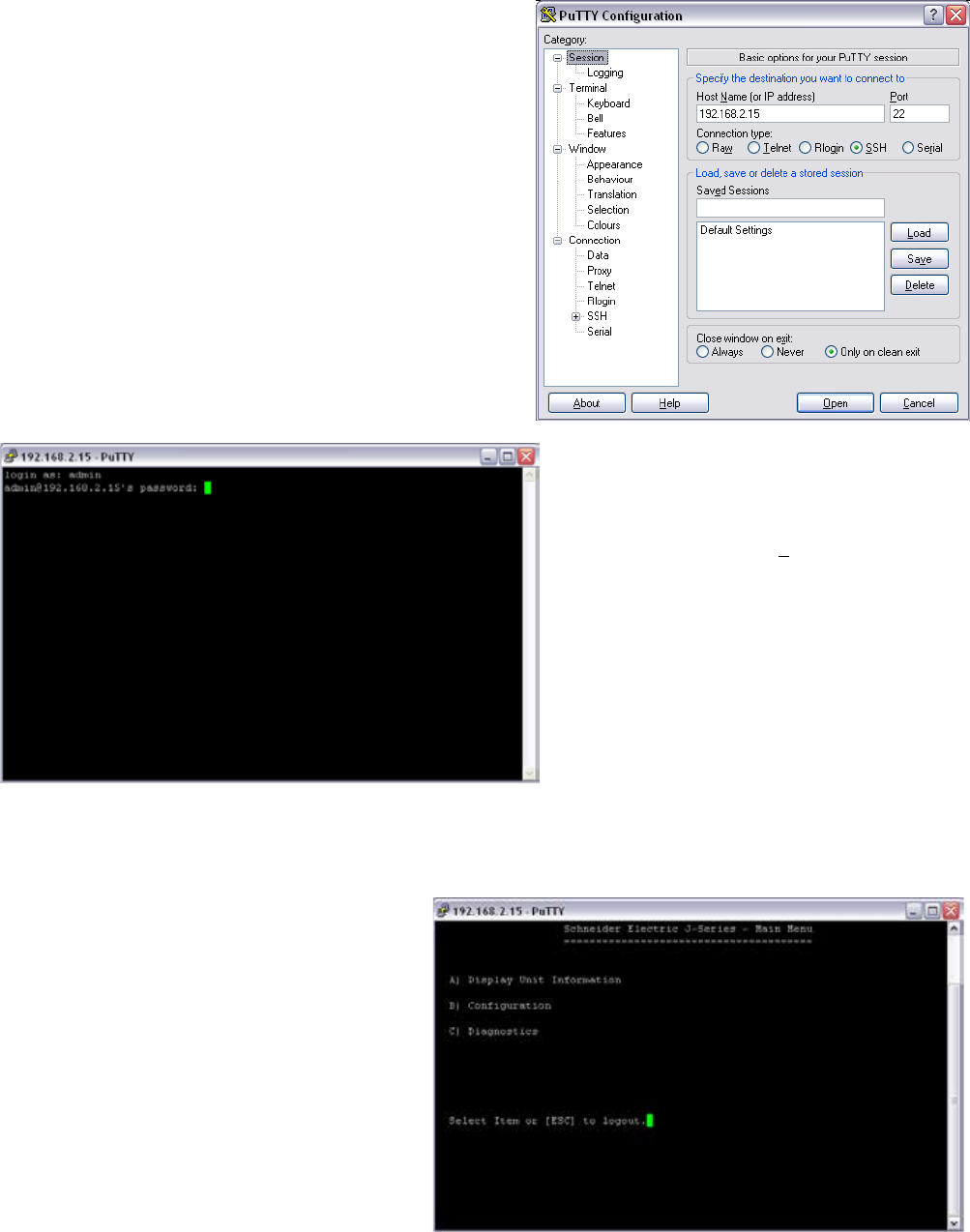
128 Document Number: 0100SM1401 Issue: 12-16
Once the correct user name and password
have been entered, the Q data radio will grant
access to the TUI main menu.
Configure the SSH client (in this case PuTTY) to interface
correctly with the embedded Q data radio’s SSH server.
The Port number for the embedded Q data radio’s
SSH terminal is 22. This is a standard and is not user
definable.
The SSH terminal also requires a user name and
password to be configured. Upon logging into the Q
data radio via SSH, the user will be prompted for the
user name and password.
Part H – Advanced
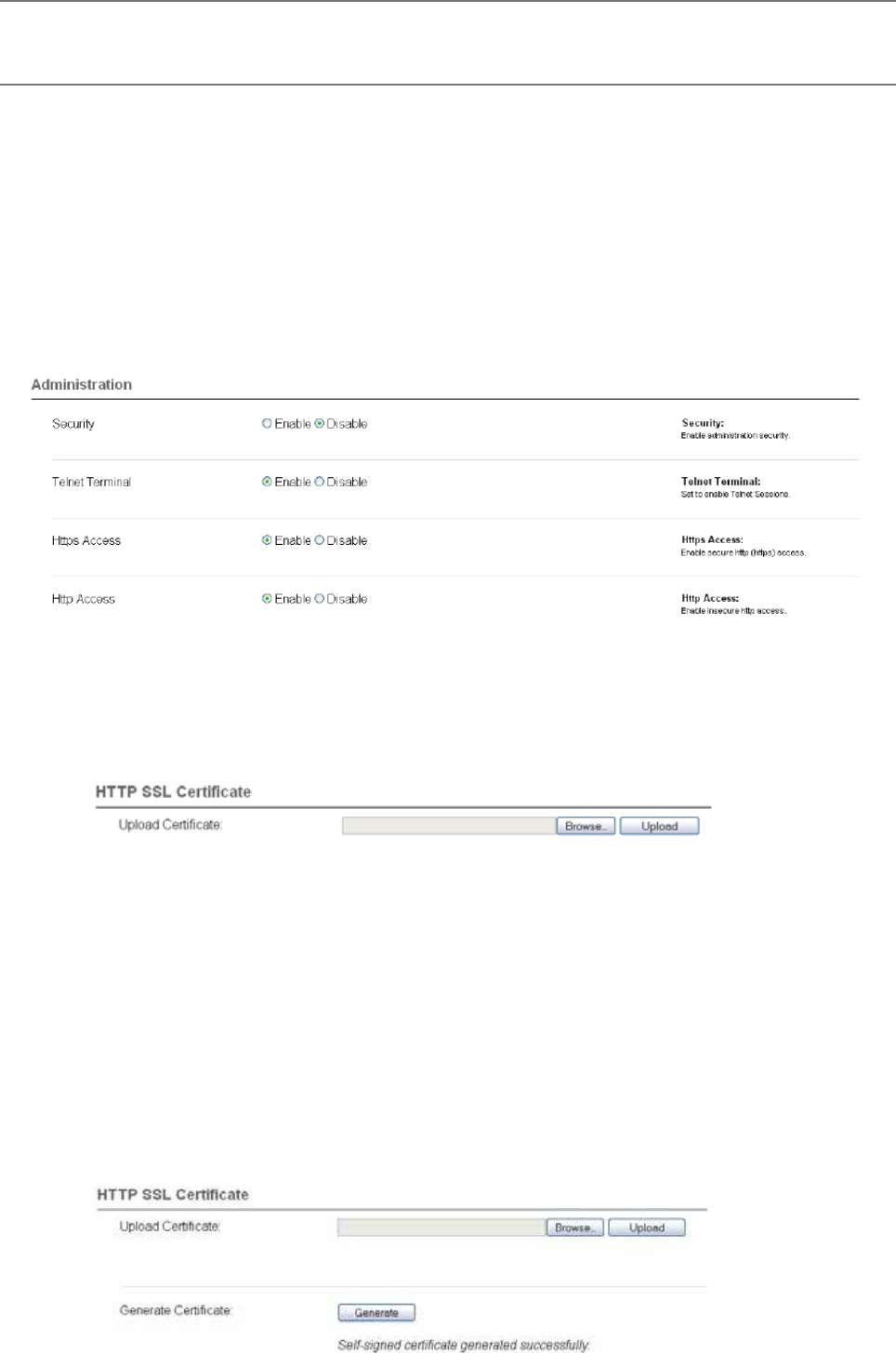
129
Document Number: 0100SM1401 Issue: 12-16
HTTP Secure (HTTPS)
The Q data radio’s web user interface can be accessed through a secure HTTP (HTTPS) connection.
There are multiple steps required to establish a successful HTTPS connection to a Q data radio, which include:
• Enabling HTTPS within the Q data radio.
• Loading a signed, digital certificate into the Q data radio. This may be generated by a certificate server (i.e. Active
directory) or can be self-generated by the Q data radio.
• Resolving web browser issues.
Once the above steps have been completed, enter “HTTPS://xxx.xxx.xxx.xxx” where ‘x’ is the unit’s IP address, into the web
browsers URL bar and press enter.
Enabling HTTPS within a Q data radio:
Browse to the unit’s Security page (Setup -> Security) and under the Administration heading, you are able to enable/disable
HTTPS. You also have the option to disable HTTP access once HTTPS is enabled.
Loading a digitally signed certificate into a Q data radio:
Certificate Management Server:
A certificate can be generated and signed from a certificate management server. Once a certificate is signed, it should then
be loaded into the Q data radio. An example of commonly used certificate management server is Active directory. For each
individual unit, a unique certificate is required. Certificates used are bound to each unit by its IP address and serial number. If the
IP address of a unit is changed, the certificate needs to be re-generated and re-loaded back into the Q data radio.
To load a signed certificate into a Q data radio via the WUI, browse to the Security Management page (Maintenance ->
Security management) and select the ‘Browse’ button.
Verify the correct file has been selected, then press the ‘Upload’ button.
Once the certificate has been successfully uploaded, a message will appear and information about the certificate will be
visible within the current certificate section.
Unless the certificate management server has been linked to the web browser as a trusted certificate server, the browser
may display security messages upon entry to the Q data radio WUI via HTTPS. To add exceptions into the browser for these
security messages see the instructions on the following page.
Self signed certificate:
A self signed certificate can easily be generated from within the Q data radio. To generate a self signed certificate, browse to
the security update page (Maintenance -> Security maintenance) and select the ‘Generate’ button.
Once the self signed certificate has been created, a message will appear and information about the certificate will be visible
within the current certification section.
Web User Interface (WUI)
The Web User Interface can be access via a HTTP connection or a HTTPS connection. For instructions on how to access the
WUI via a HTTP connection, refer to the Quick Reference Guide section within this manual.
Part H – Advanced
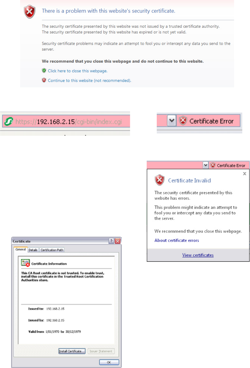
130 Document Number: 0100SM1401 Issue: 12-16
Resolving web browser issues:
Every web browser has a list of trusted Certification Authorities (CAs). When either a CA that is not included within the web
browsers trusted list is used to sign a certificate, or a self signed certificate is used, a security message will appear within the
web browser when an attempt to access a Q data radio’s WUI via HTTPS is made. See the example below (Example uses
internet explorer 8).
Once the ‘View certificates’ button is selected, a certificate
information window will open. Once this window has opened,
select the ‘Install Certificate..’ button.
If you cannot see the ‘Install Certificate..’ button, restart Internet
explorer in administration mode. Do this by right clicking the
Internet Explorer icon on the desktop and selecting ‘open in
administrator mode’. If this selection is not available, speak to
your system administrator.
Click on the ‘Certificate Error’ window within the URL bar as
shown. This will open a Certificate invalid window, click on the
‘View certificates’ button.
Although the Browser is identifying this, a secure connection should still be in place between the browser and the Q data radio.
To add the signer to the browser’s trusted list, follow the steps shown below.
This security message is identifying the fact that the signee of the certificate being read is not within the browser’s trusted list.
Pressing the ‘Continue to this website (not recommended)’ button will allow a HTTPS connection through to the Q data radio.
The URL bar of the browser will still indicate that the certificate is still not trusted.
Part H – Advanced
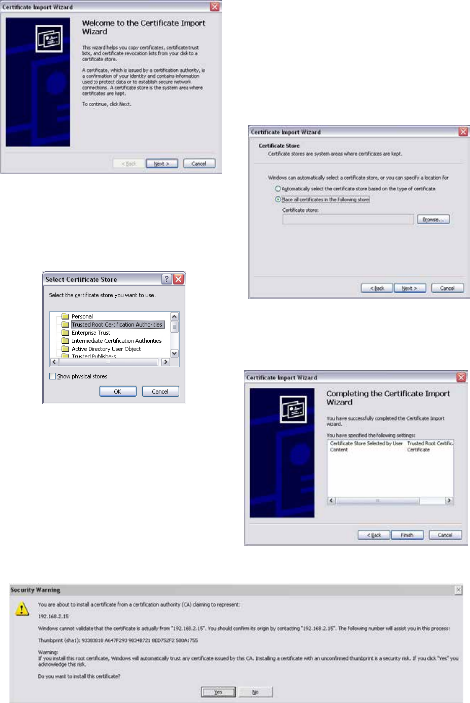
131
Document Number: 0100SM1401 Issue: 12-16
This will start the certificate import wizard. Select the Next
button.
Select the ‘Place all certificates in the following store’ option
and press the ‘Browse...’ button.
Select the ‘Trusted Root Certification Authorities’ folder and
press the ‘OK’ button.
Once the import directory has been selected, press the
‘Finish’ button.
A security message will appear providing information about the added certificate exception. Press the ‘Yes’ button
to complete the installation process.
Part H – Advanced
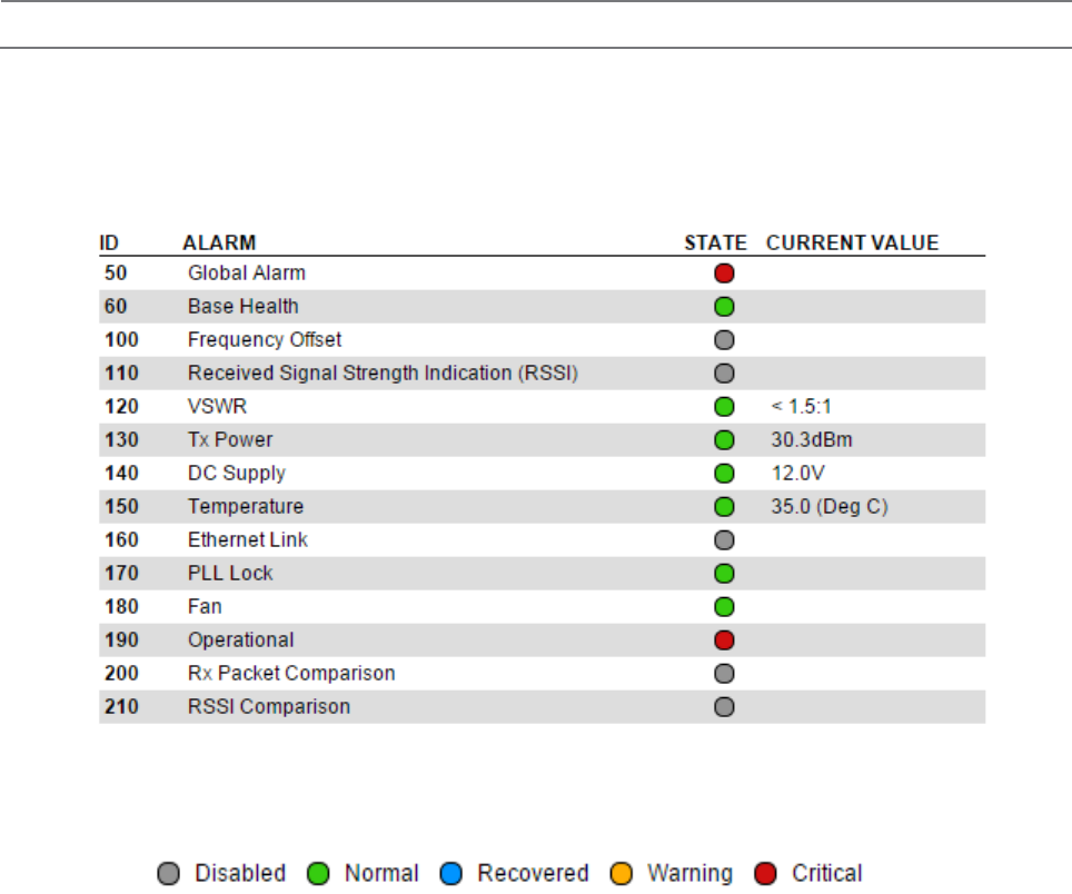
132 Document Number: 0100SM1401 Issue: 12-16
Ease of Use
Part H – Advanced
Alarms
Introduction
The Q data radio can monitor the condition of various diagnostic and operating parameters (i.e DC volts, Tx Power, etc). The radio’s
active alarms can be evaluated by observing the event history and alarm states.
The alarm states can be viewed within the Monitoring section of the Web User Interface (Monitoring -> Alarms and Events).
Alarm States
Depending on active values of monitored alarms, the alarm states can be displayed in different levels of severities, including:
• Disabled: The alarm is not being monitored.
• Normal: The alarm value is in normal (acceptable) operating conditions.
• Recovered: The alarm has recovered from a warning or critical state, back into normal operating conditions, the alarm state
will remain in a recovered state, until either, the alarms are reset (by clicking the reset alarms button at the top corner of the
window) or the alarm state changes again.
• Warning: The alarm is within the warning threshold limits defined by the user.
• Critical: The alarm is outside of the hardware limits of the radio (alarms which can reach critical severity, can not be disabled).
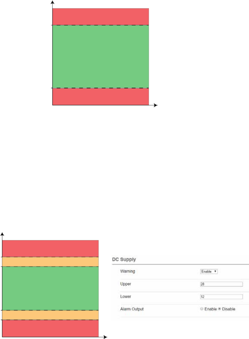
133
Document Number: 0100SM1401 Issue: 12-16
Configuration
The diagram below provides an example of how an alarm state can be deemed ‘Normal’ or ‘Critical’. The example shows the
value thresholds for the normal and critical state of the DC supply in a QB. Once a DC supply measurement is taken, the
behavior of the alarm state reporting structure is as follows:
• Normal: If the value falls within the green zone (11 to 30 VDC) the alarm state can display ‘normal’ as this is an acceptable
operating value.
• Critical: If the value falls within the red zone (below 11 VDC or above 30 VDC) the alarm state can display ‘critical’ as these
values are the hardware limits of the radio (the radio may switch off or self protect depending on the extremity of the critical
value).
Warning State
Enable/Disable the warning state for the respective alarm being configured. The warning state can help prevent a critical
alarm from occurring, by indicating an alarm value has been measured outside of ‘normal’ operating conditions, but, still
within ‘critical’ operating conditions. This means a warning alarm can be active, before a critical alarm state is reached.
Once the warning alarm is enabled, a limit/threshold should be configured. The diagram below provides an example of how
the warning alarm is implemented into the alarm state reporting structure for the DC supply in a QB. Once a DC supply
measurement is taken, the behavior of the alarm state reporting structure is as follows:
• Normal: If the value falls within the green zone (12 to 28 V) the alarm state can display ‘normal’ as this is an acceptable
operating value.
• Warning: If the value falls within the amber zone (11 to 12 V OR 28 to 30V) the alarm state can display ‘warning’ as this is
has been configured by the user to be outside of normal operating conditions.
• Critical: If the value falls within the red zone (below 11 V or above 30 V) the alarm state can display ‘critical’ as these values
are the hardware limits of the radio (the radio may switch off or self protect depending on the extremity of the critical
value).
DC Supply (V)
30 V
11 V
Normal
Critical
Critical
0 V
Time (T)
DC Supply (V)
30 V
11 V
Normal
Critical
Critical
0 V
Time (T)
Warning
Warning
12 V
28 V
Alarm State Diagram 1
Alarm State Diagram 2
Part H – Advanced

134 Document Number: 0100SM1401 Issue: 12-16
Global Alarm
The global alarm reflects the highest severity state of all the alarm states being monitored. This
can allow a user to monitor the global alarm state, and if/when the alarm state changes, a detailed
review of the radio’s operating condition can be performed.
Subscriptions available SNMP Notifications
Operational
The operational alarm will display a critical state during situations that cannot be resolved by
the user through factory default, configuration or firmware upgrade. While an operation alarm is
critical, the radio’s transmitter may become disabled.
Subscriptions available SNMP Notifications, Alarm Output
Alarm Specifications
To perform alarm configuration, go to: Setup -> Alarms
Temperature
Units of measurement available Celsius, Fahrenheit
State Change Hysteresis 1 Deg C (1.8 Deg F)
Subscriptions available SNMP Notifications, Alarm Output
Critical Alarm
Upper Critical Alarm Threshold 81 Deg C (177.8 Deg F)
Lower Critical Alarm Threshold -40 Deg C (-40 Deg F)
Warning Alarm
Default Upper Warning Alarm Threshold 70 Deg C (113 Deg F)
Default Lower Warning Alarm Threshold -10 Deg C (14 Deg F)
Configurable Warning Alarm Threshold Range -40 to 70 Deg C (-40 to 158 Deg F)
Frequency Offset
Units of measurement available Hz
State Change Hysteresis 5 Hz
Subscriptions available SNMP Notifications
Warning Alarm
Default Upper Warning Alarm Threshold 1000 Hz
Default Lower Warning Alarm Threshold -1000 Hz
Configurable Warning Alarm Threshold Range 3000 to -3000 Hz
RSSI
Units of measurement available dBm
State Change Hysteresis 1 dBm
Subscriptions available SNMP Notifications
Warning Alarm
Default Upper Warning Alarm Threshold -50 dBm
Default Lower Warning Alarm Threshold -120 dBm
Configurable Warning Alarm Threshold Range -140 to 0 dBm
Part H – Advanced
135
Document Number: 0100SM1401 Issue: 12-16
VSWR
Measurement taken Ratio
Subscriptions available SNMP Notifications, Alarm Output
Critical Alarm
Upper Critical Alarm limit 10:1
Warning Alarm
Default Warning Alarm Limit 3:1
Configurable Warning Alarm Limits 1.5:1, 2:1 or 3:1
Part H – Advanced
DC Supply
Units of measurement available DC Volts
State Change Hysteresis 0.5V DC
Subscriptions available SNMP Notifications, Alarm Output
Critical Alarm
Upper Critical Alarm Threshold 30V DC
Lower Critical Alarm Threshold 10V DC
Warning Alarm
Default Upper Warning Alarm Threshold 28V DC
Default Lower Warning Alarm Threshold 12V DC
Configurable Warning Alarm Threshold Range 10 to 30 V DC
Ethernet Link
The Ethernet link monitor will send pings to a user defined IP address. The radio can raise a
warning alarm, if a ping response is not received from the specified IP device.
Subscriptions available SNMP Notifications, Alarm Output
Warning Alarm
Primary IP The primary IP address to test
Secondary IP The secondary IP address to test
Fail Threshold The number of failed pings allowed before
an alarm is raised
Retry Interval The number of seconds to wait before
retrying a failed ping
Tx Power
Units of measurement available dBm
State Change Hysteresis 2 dBm
Subscriptions available SNMP Notifications,
Alarm Output (QB & QP only)
Critical Alarm
A Critical alarm will be raised if the radio detects a Tx power level which is +/- 2dBm of the
target Tx power.
PLL Lock
A critical alarm can be raised if a PLL has been detected out of lock.
Subscriptions available SNMP Notifications, Alarm Output

136 Document Number: 0100SM1401 Issue: 12-16
QB and Hot Standby Specific Alarm Specifications
Fan
A critical alarm can be raised if a fan alarm has been detected.
Subscriptions available SNMP Notifications, Alarm Output
Rx Packet Comparison
A hot standby radio can compare the amount of good packets received by radio A and radio B.
A warning alarm can be raised if the differential between good packets received by the configured
radio and good packets received by the alternate radio is greater than the specified differential.
Primarily used in separate antenna arrangements.
Subscriptions available SNMP Notifications, Alarm Output
Warning Alarm
Default Differential Value (%) 20 %
RSSI Comparison
A hot standby radio can compare the level of RSSI received by radio A and radio B. A warning
alarm can be raised if the reported RSSI of the configured radio is lower than the reported RSSI
of the alternate radio by the specified margin (dB).
An offset should be used where the configured radio has an expected reduced RSSI, compared
to that of the alternate radio.
The offset can help detect RSSI compare alarms more accurately within a Hot standby
arrangement which utilises separate antennas for each radio.
The Margin and Offset are configured as a negative number
Subscriptions available SNMP Notifications, Alarm Output
Warning Alarm
Default Margin Value (dB) -10 dB
Default Offset Value (dB) 0
The following hot standby specific alarms can only be configured once HSC mode has been enabled within the radio. To
enable HSC mode, go to: Setup -> Basestation
Part H – Advanced
Base Health
The base health alarm is a warning indicator (alarm state can be either normal or warning),
which is subscribed to the radio’s alarm output. This can allow a user to monitor the base health
alarm state, and if/when the alarm state changes, a detailed review of the radio’s operating condition
can be performed.
Subscriptions available SNMP Notifications
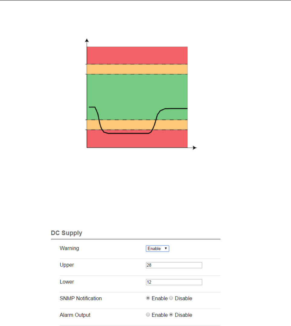
137
Document Number: 0100SM1401 Issue: 12-16
Alarm Subscription:
Services can be subscribed to alarm state changes for respective alarms. Depending on which service is enabled, a state
change can either raise an alarm output, or, send a notification.
The diagram below provides an example of a DC supply dropping and recovering over time.
Time (T)
Alarm Subscription Diagram 1
SNMP
The SNMP notifications service can be subscribed to an alarm. This can cause an SNMP notification to be sent to the
configured SNMP NMS each time a subscribed alarm changes state. Referring to the example above, an SNMP notification
would be sent during each alarm state change.
The SNMP agent and notifications section should be enabled and configured (Setup -> SNMP) before the SNMP notification
service can be subscribed to alarms (review the SNMP section for information on the SNMP agent configuration).
To subscribe the SNMP notification service to an alarm, go to Setup -> Alarms, and enable ‘SNMP Notification’ for the
respective alarm being subscribed to.
DC Supply (V)
30 V
11 V
0 V
12 V
28 V
Part H – Advanced
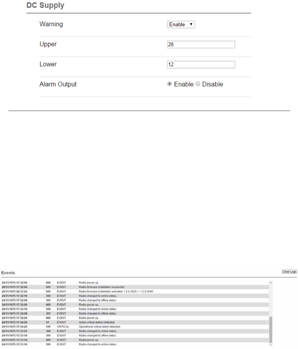
138 Document Number: 0100SM1401 Issue: 12-16
Alarm Output
Available in QB & QP hardware only. The radio alarm output is an internal dual-state indicator (ON/OFF) which can control the
dynamic changeover mechanism within a QH (QB with HSC mode enabled) and a QP.
By subscribing the alarm output service to an alarm, the alarm output will turn ON when any subscribed alarm has reached
the highest level of alarm severity and will turn OFF when no subscribed alarms are in their highest level of alarm severity.
To subscribe the alarm output service to an alarm, go to Setup -> Alarms, and enable ‘Alarm Output’ for the respective alarm
being subscribed to.
Events
Introduction
The Q data radios can log meaningful events that occur thought the operation of the radio. These events are viewable within the
monitoring section (Monitoring -> Alarms and Events).
Each event that is recorded includes the following information:
• Time Stamp: The time stamp is only accurate, when the time configuration has been set (Setup -> Network). If the time
configuration has not been set, the default starting time for the radio will be used.
• Event ID: Each type of event has a unique event identification number. The event IDs and corresponding event descriptions
are shown within tables on the following pages.
• Severity: There are different event severities depending on the respective event:
- EVENT: This is an indicative event to record behaviour of the radio (i.e power up, firmware update).
- NORMAL: This indicates that the recorded event is within acceptable operating conditions
- WARNING: This indicates that the recorded event is within configured warning conditions
- CRITICAL: This indicates that the recorded event may cause the radio to stop operating.
• Notes: Description of the event which has occurred.
The event log window can be cleared by selecting the ‘Clear Logs’ button at the top corner of the event log window.
Part H – Advanced

139
Document Number: 0100SM1401 Issue: 12-16
Alarm Events:
Event ID Description
50 Active warning alarm detected
51 Active critical alarm detected
52 Active critical alarm cleared
53 Active warning alarm cleared
60 Base health alarm detected
61 Base health alarm cleared
100 Frequency offset warning detected
101 Frequency offset warning alarm cleared
110 Received signal level (RSSI) warning alarm detected
111 Received signal level (RSSI) warning alarm cleared
120 High VSWR warning alarm detected
121 High VSWR critical alarm detected
122 High VSWR critical alarm cleared
123 High VSWR warning alarm cleared
130 Transmit power target critical alarm detected
131 Transmit power target critical alarm cleared
140 DC supply warning alarm detected
141 DC supply critical alarm detected
142 DC supply critical alarm cleared
143 DC supply warning alarm cleared
150 Radio Temperature warning alarm detected
151 Radio Temperature critical alarm detected
152 Radio Temperature critical alarm cleared
153 Radio Temperature warning alarm cleared
160 Ethernet link warning alarm detected
161 Ethernet link warning alarm detected cleared
170 PLL Lock critical alarm detected
171 PLL Lock critical alarm cleared
180 FAN critical alarm detected
181 FAN critical alarm cleared
190 Operational critical alarm detected
191 Operational critical alarm cleared
330 Received good data warning alarm detected
331 Received good data warning alarm cleared
340 Good RSSI comparison warning alarm detected
341 Good RSSI comparison warning alarm cleared
Part H – Advanced
140 Document Number: 0100SM1401 Issue: 12-16
Event ID Description
300 Radio changed to online status
301 Radio changed to offline status
310 Radio forced to offline
311 Radio forced to online
320 Radio period change-over timer expired.
Hot Standby Specific Events:
Event ID Description
400 Radio power up
401 User initiated radio reset
402 Watch dog initiated radio reset
403 NTP date/time locked
404 PTT timeout timer activated
Operational Events:
Event ID Description
500 Radio firmware installation activated
501 Radio firmware installation successful
502 Radio firmware installation unsuccessful
510 Factory default reset activated
511 Factory default reset successful
512 Factory default reset unsuccessful
520 Radio configuration change activated
521 Radio configuration change successful
522 Radio configuration change unsuccessful
Management Events:
Part H – Advanced
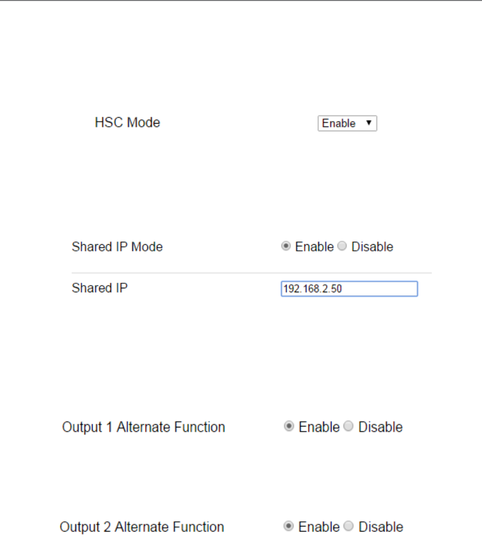
141
Document Number: 0100SM1401 Issue: 12-16
Base Station
Introduction
Base station hardware (QP and QB) have specific configuration parameters for hardware specific features. To access these
configuration parameters go to: Setup -> Basestation.
HSC (Hot Standby Controller) Mode
Only configurable within a QB (a QP always has this enabled), this should be enabled when a QB is operating within a hot
standby arrangement.
Shared IP Address
Radio A and Radio B within a hot standby arrangement can be configured to ‘share’ an IP address. This is a separate IP
address from each radio’s unique IP address. The shared IP address can be used to access the current ‘online’ radio.
The shared IP address should be configured in radio A & B as the same IP address.
The shared IP address is only available once HSC mode is enabled (a QP always has HSC mode enabled).
General Purpose Digital I/O (GPIO)
The digital outputs can be configured to reflect the status of different operating conditions. By disabling either of the
following parameters, the respective digital output can be set manually by the user (TView Diagnostics or SNMP can be used
to set the digital output).
Output 1 Alternate Function - When enabled, digital output 1 will subscribe to the base health status (the base health alarm
can reflect the status of the alarm output. See the alarms section for further detail). If the output is active, the base health
alarm is in warning state.
Part H – Advanced
Output 2 Alternate Function - When enabled, digital output 2 will reflect which radio of a hot standby arrangement is online.
When the output is inactive: Base A is online
When the output in active: Base B is online
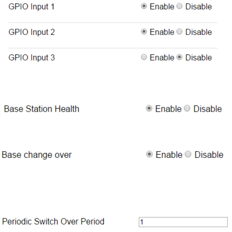
142 Document Number: 0100SM1401 Issue: 12-16
SNMP Notifications
Configure the radio to send SNMP notifications when a respective event occurs.
GPIO Inputs - By enabling SNMP notification on a GPIO input, the radio will send an SNMP notification to the NMS specified in
the configured SNMP section (to access SNMP, go to: Setup -> SNMP), when the respective digital input state changes.
Advanced
Periodic Switch Over Period - The period, in hours, after which the online base station will initiate an automatic switch over.
This can be useful, to exercise each radio within a hot standby arrangement, to validate redundant link availability.
Setting a value of zero will disable this feature.
Base Station Health - By enabling the Base Station Health SNMP notification, the radio will send an SNMP notification to the
NMS specified in the configured SNMP section (to access SNMP, go to: Setup -> SNMP), when a change in alarm state for the
base health alarm occurs.
Base change over - By enabling the Base change over SNMP notification, the radio will send an SNMP notification to the NMS
specified in the configured SNMP section (to access SNMP, go to: Setup -> SNMP), when a hot standby base change over
occurs.
Part H – Advanced
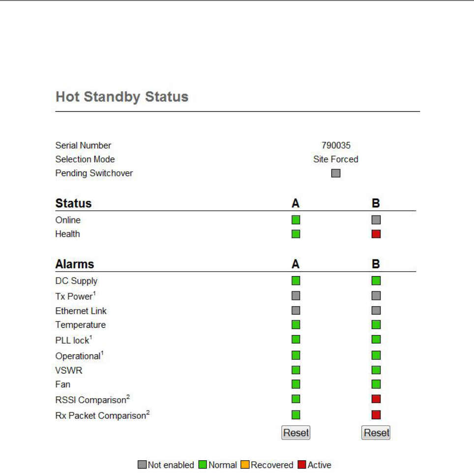
143
Document Number: 0100SM1401 Issue: 12-16
Hot Standby Status
Introduction
The active condition of a hot standby can easily be reviewed via the hot standby status window. To access this window, go to:
Monitoring -> Hot Standby Status.
Alarms for a particular radio can be reset, by clicking the Reset button at the bottom of the respective radios alarms column.
Latched Alarms
Once some alarms within a radio have been detected in a their most severe state, the hot standby will no longer dynamically
switch over to that radio, to help prevent switching over to a non-functional radio. These type of alarms are called ‘Latching
Alarms’.
Latching alarms may be reported in a recovered state, but will prevent the hot standby from dynamically changing over to the
respective radio, until the alarms have been manually reset.
The list of latching alarms include:
• Tx Power
• PLL Lock
• Operational
A Manual changeover on the front panel switch, or remotely forces change-over, can over-ride, but not clear, a latched alarm.
Part H – Advanced

144 Document Number: 0100SM1401 Issue: 12-16
SNMP - Diagnostic objects and Notifications
Introduction
The Q data radio’s SNMP Interface supports:
• Supports RFC1213 (Unit name, Unit Location, Firmware, Uptime, etc). Details about RFC1213 and the SNMP
parameters included in this standard can be found in this link : http://www.ietf.org/rfc/rfc1213.txt
• Supports Radio and Ethernet Diagnostics (as seen in the HTML Diagnostics overview)
• SNMP V1 & V2c
• SNMP notifications which include traps and informs
MIB Files
Distributed with the Q data radio firmware are two MIB files which provide structure definitions for the SNMP objects. The
MIB files are suitable for importation into most common SNMP browsers. Definitions for each SNMP object are noted as
comments in the MIB files. Only a summary of each object is noted in this user manual.
SNMP user alarm detection
The Trio Q data radio range can detect a number of SNMP alarms which have been raised due to varying radio diagnostic
values. These diagnostic values include:
• VSWR
• Supply Voltage
• Temperature
• RSSI
• Transmit Power
Each SNMP alarm for the diagnostic values shown above, has a maximum of three alarm states. Each one is also represented
with a status number. The alarm states and corresponding numbers are as follows:
• Normal state - 1: The ‘Normal’ state will be displayed within an alarm when a diagnostics parameter is operating
within normal limits.
• User alarm state - 2: A ‘User alarm’ state will be displayed when a diagnostics parameter within the Q data radio falls
outside of the user defined alarm limits. User limits are configurable within the Q data radio.
• Critical alarm state- 3: A ‘Critical alarm’ state will be displayed when a diagnostics parameter within the Q data radio
falls outside of the unit’s hardware specification.
SNMP critical alarm detection
The Trio Q data radio range can detect a number of SNMP alarms which have been raised due to the operational state of the
radio. These operational states include:
• Transmitter PLL locked
• Receiver PLL locked
• Operational alarm detected
• Fan alarm detected (QB, QP & QH only)
Each SNMP alarm for the operational states shown above, has a maximum of two alarm states. Each one is also represented
with a status number. The alarm states and corresponding numbers are as follows:
• Yes state - 1: The ‘Yes’ state will be displayed if the corresponding operational state is active/true.
• No state - 2: The ‘No’ state will be displayed if the corresponding operational state is inactive/false.
Notifications
SNMP notifications are unsolicited SNMP messages designed to inform a user when an SNMP alarm state change has been
detected. The Q data radio range supports two types of notifications:
• Traps: are low bandwidth consuming UDP notifications that have no requirement for a response. If the message is lost
along the way to the destination IP address, the message will be lost.
• Informs: are essentially traps, that require a response from the destination IP address once a notification has been
sent. This gives informs more reliability getting to a destination as the Q data radio range supports retries and time
out periods.
Part H – Advanced

145
Document Number: 0100SM1401 Issue: 12-16
Summary of SNMP MIB Objects Supported
Object name Object Identifier (OID) Syntax Object description
General Group:
serialNumber .1.3.6.1.4.1.33302.30.1.1.0 String Serial number of the Q data radio
modelNumber .1.3.6.1.4.1.33302.30.1.2.0 String Model number of the Q data radio
hardwareRevision .1.3.6.1.4.1.33302.30.1.3.0 String Hardware revision of the Q data radio
firmwareRevision .1.3.6.1.4.1.33302.30.1.5.0 String The firmware revision the Q data radio
date .1.3.6.1.4.1.33302.30.1.6.0 String The date as reported by the Q data radio
time .1.3.6.1.4.1.33302.30.1.7.0 String The time as reported by the Q data radio
utcTimeOffset .1.3.6.1.4.1.33302.30.1.8.0 String Time offset from UTC for the Q data radio’s
local time zone
upTime .1.3.6.1.4.1.33302.30.1.9.0 String The uptime of the Q data radio
primaryNtpServer .1.3.6.1.4.1.33302.30.1.10.0 String Primary Network Time Protocol (NTP) domain
name
cpuLoad .1.3.6.1.4.1.33302.30.1.11.0 Integer Average CPU utilisation (%) for the past 15
minutes
supplyVoltage .1.3.6.1.4.1.33302.30.1.12.0 Integer Supply Voltage of the Q data radio in mV
TemperatureTable .1.3.6.1.4.1.33302.30.1.13.0 Table Table of radio temperatures.
ipAddress .1.3.6.1.4.1.33302.30.1.15.0 IP Address The IP address of the Q data radio.
Radio Group:
radioReceivedPackets .1.3.6.1.4.1.33302.30.2.3.0 Counter Number of packets received from over the
radio link
radioTrasnmittedPackets .1.3.6.1.4.1.33302.30.2.4.0 Counter Number of packets transmitted over the radio
link
radioForwardPowerTable .1.3.6.1.4.1.33302.30.2.5.0 Table Table of radio forward powers.
radioReversePowerTable .1.3.6.1.4.1.33302.30.2.6.0 Table Table of radio Reverse powers.
radioVswrTable .1.3.6.1.4.1.33302.30.2.7.0 Table Table of radio VSWR’s
radioRssiTable .1.3.6.1.4.1.33302.30.2.8.0 Table Table of RSSI values.
radioDataRate .1.3.6.1.4.1.33302.30.2.15.0 Integer The over-the-air data rate of the Q data radio.
[Dynamic(0), 8000bps(1),14000bps(2),
16000bps(3), 24000bps(4), 28000bps(5),
32000bps(6), 42000bps(7), 56000bps(8),
9600bps(9), 19200bps(10), 2400bps(11),
4800bps(12)]
txFrequency .1.3.6.1.4.1.33302.30.2.18.0 Integer Radio’s transmit frequency (Hz).
rxFrequency .1.3.6.1.4.1.33302.30.2.19.0 Integer Radio’s receive frequency (Hz).
muteThreshold .1.3.6.1.4.1.33302.30.2.20.0 Integer Radio’s mute threshold (dBm).
rxGoodFrameCount .1.3.6.1.4.1.33302.30.2.23.0 Counter Good frames received.
rxGoodByteCount .1.3.6.1.4.1.33302.30.2.24.0 Counter Good bytes received.
rxBadFrameCount .1.3.6.1.4.1.33302.30.2.25.0 Counter Bad frames received.
rxAverageGoodFrameSize .1.3.6.1.4.1.33302.30.2.26.0 Integer Average received good frame size.
rxAverageFrameRate .1.3.6.1.4.1.33302.30.2.27.0 Integer Average receive frame rate.
rxChannelOccupancy .1.3.6.1.4.1.33302.30.2.28.0 Integer Receive channel occupancy.
rxSlidingChannelOccupancy .1.3.6.1.4.1.33302.30.2.29.0 Integer Sliding channel occupancy.
txByteCount .1.3.6.1.4.1.33302.30.2.31.0 Counter Transmitted byte counter.
txFrameCount .1.3.6.1.4.1.33302.30.2.32.0 Counter Transmit frame count.
txAverageFrameSize .1.3.6.1.4.1.33302.30.2.33.0 Integer Transmit average frame size.
txAverageFrameRate .1.3.6.1.4.1.33302.30.2.34.0 Integer Transmit average frame rate.
radioFrequencyError .1.3.6.1.4.1.33302.30.2.36.0 Integer Radio frequency error (Hz).
Part H – Advanced

146 Document Number: 0100SM1401 Issue: 12-16
Object name Object Identifier (OID) Syntax Object description
Security Group:
snmpVersion .1.3.6.1.4.1.33302.30.3.1.0 Integer Default SNMP version
consoleLoginStatus1 .1.3.6.1.4.1.33302.30.3.2.0 Integer Console login status for COM1
consoleLoginStatus2 .1.3.6.1.4.1.33302.30.3.3.0 Integer Console login status for COM2
numberOfActiveTelnetSessions .1.3.6.1.4.1.33302.30.3.4.0 Integer Number of active Telnet sessions
TelnetSessionTable .1.3.6.1.4.1.33302.30.3.5.0 Table Table of Telnet and Ssh sessions
encryptionStatus .1.3.6.1.4.1.33302.30.3.11.0 Integer Encryption status
ETH Group:
ethInterfaceTable .1.3.6.1.4.1.33302.30.4.1.0 Table Table of network interfaces
interfaceName .1.3.6.1.4.1.33302.30.4.1.1.2.x String Ethernet interface (row) name (where x is
the Ethernet interface - 1 [ETH1], 2 [ETH2]
or 3[(ETH3])
interfaceStatus .1.3.6.1.4.1.33302.30.4.1.1.3.x Integer Ethernet interface (row) name (where x is
the Ethernet interface - 1 [ETH1], 2 [ETH2]
or 3[(ETH3])
interfaceSpeed .1.3.6.1.4.1.33302.30.4.1.1.4.x Integer Ethernet interface (row) name (where x is
the Ethernet interface - 1 [ETH1], 2 [ETH2]
or 3[(ETH3])
interfaceMode .1.3.6.1.4.1.33302.30.4.1.1.5.x Integer Ethernet interface (row) name (where x is
the Ethernet interface - 1 [ETH1], 2 [ETH2]
or 3[(ETH3])
Part H – Advanced
Alarm Group:
operationalAlarm .1.3.6.1.4.1.33302.30.5.1.0 Integer Operational alarm
rxPllLocked .1.3.6.1.4.1.33302.30.5.2.0 Integer Receiver PLL lock status
radioVswrAlarmTable .1.3.6.1.4.1.33302.30.5.10.0 Table Table of VSWR alarms
radioVswrAlarmState .1.3.6.1.4.1.33302.30.5.10.1.2.1 Integer High VSWR
Normal =Operating within normal conditions,
UserAlarm =Operating outside of user
specified limits,
CriticalAlarm =Operating outside of specified
operating limits.
Recovered =Normal operating conditions
restored.
externalSupplyVoltageAlarmState .1.3.6.1.4.1.33302.30.5.11.0 Integer External supply voltage
Normal =Operating within normal conditions,
UserAlarm =Operating outside of user
specified limits,
CriticalAlarm =Operating outside of factory
specified operating limits.
Recovered =Normal operating conditions
restored.
temperatureAlarmState .1.3.6.1.4.1.33302.30.5.12.0 Integer Internal temperature.
Normal =Operating within normal conditions,
UserAlarm =Operating outside of user
specified limits,
CriticalAlarm =Operating outside of specified
operating limits.
Recovered =Normal operating conditions
restored.
radioRssiAlarmTable .1.3.6.1.4.1.33302.30.5.13.0 Table Table of radio RSSI alarm states
radioRssiAlarmState .1.3.6.1.4.1.33302.30.5.13.1.2.1 Integer RSSI
Normal =Operating within normal conditions,
UserAlarm =Operating outside of user
specified limits.
Recovered =Normal operating conditions
restored.

147
Document Number: 0100SM1401 Issue: 12-16
Part H – Advanced
Alarm Group (Continued):
radioTxPowerAlarmTable .1.3.6.1.4.1.33302.30.5.14.0 Table Table of radio tx power alarms.
radioTxPowerAlarmState .1.3.6.1.4.1.33302.30.5.14.1.2.1 Integer Tx Power
Normal =Operating within normal conditions,
CriticalAlarm =Operating outside of specified
operating limits.
Recovered =Normal operating conditions
restored.
globalAlarmState .1.3.6.1.4.1.33302.30.5.15.0 Integer Global Monitored Alarm.
Normal =All monitored parameters are
operating within normal conditions,
UserAlarm =One or more monitored
parameters are operating outside of user
specified limits,
CriticalAlarm =One or more monitored
parameters are operating outside of factory
specified operating limits.
Recovered =One or more monitored
parameters had its normal operating
conditions restored.
txPllLocked .1.3.6.1.4.1.33302.30.5.17.0 Integer Transmit PLL lock status
radioFrequencyOffsetAlarmState .1.3.6.1.4.1.33302.30.5.18.0 Integer Frequency error state.
Normal =Operating within normal conditions,
UserAlarm =Receive frequency error out of
user specified limits.
Recovered =Normal operating conditions
restored.
radioPllLockedAlarmState .1.3.6.1.4.1.33302.30.5.19.0 Integer Normal =Operating within normal conditions,
CriticalAlarm =Tx/Rx PLL failed to lock,
Recovered =Normal operating conditions
restored.
radioRssiCompareAlarmState .1.3.6.1.4.1.33302.30.5.20.0 Integer Normal =Operating within normal conditions,
UserAlarm =Rssi compared with paired unit
dropped below user specified limits,
Recovered =Normal operating conditions
restored.
radioGoodRxPacketAlarmState .1.3.6.1.4.1.33302.30.5.21.0 Integer Normal =Operating within normal conditions,
UserAlarm =Rx packet compared with paired
unit dropped below user specified limits,
Recovered =Normal operating conditions
restored.
ethernetLinkAlarmState .1.3.6.1.4.1.33302.30.5.22.0 Integer Normal =Operating within normal conditions,
UserAlarm =Ethernet link target unreachable,
Recovered =Normal operating conditions
restored.
resetAlarms .1.3.6.1.4.1.33302.30.5.100.0 Integer Read/Write Parameter
Reset alarms on current module.

148 Document Number: 0100SM1401 Issue: 12-16
Operational Alarm Detection
Name operationalAlarm
Alarm states Yes (1), No (2)
Alarm limits No limits, if the radio go into a operational alarm state, the object changes alarm
state to Yes (1). During normal operation, this alarm state in No (2)
Receiver PLL Lock Alarm Detection
Name rxPllLocked
Alarm states Yes (1), No (2)
Alarm limits No limits, if the radio detects the receiver PLL is no longer in lock, the object changes
alarm state to No (2). During normal operation, this alarm state in Yes (1)
Transmitter PLL Lock Alarm Detection
Name txPllLocked
Alarm states Yes (1), No (2)
Alarm limits No limits, if the radio detects the transmitter PLL is no longer in lock, the object
changes alarm state to No (2). During normal operation, this alarm state in Yes (1)
SNMP - Critical Alarm Object Specifications
Part H – Advanced

149
Document Number: 0100SM1401 Issue: 12-16
SNMP - Notifications
Customisations can be made on which SNMP alarms will be detected, along with the user alarm limits which will trigger an
alarm state change and can be sent as a notification.
To configure which alarms are to be detected or to configure the limits of a user alarm state change, see the user alarm
management section found within the SNMP page of the Q data radio web user interface. Specifications on alarms which can
be sent as notifications, can be found within the tables below:
Global Alarm Detection Notification
Notification Name notificationGloalAlarmChanged
Notification OID .1.3.6.1.4.1.33302.30.10.12
Global Alarm Detection Notification Objects
Name OID Position Specific
Code
Description
globalAlarmState .1.3.6.1.4.1.33302.30.5.15.0 0 12 Global alarm state
externalSupplyVoltageAlarmState .1.3.6.1.4.1.33302.30.5.11.0 1 12 Supply voltage alarm state
temperatureAlarmState .1.3.6.1.4.1.33302.30.5.12.0 2 12 Temperature alarm state
rxPllLocked .1.3.6.1.4.1.33302.30.5.2.0 3 12 Receiver PLL lock alarm state
txPllLocked .1.3.6.1.4.1.33302.30.5.17.0 4 12 Transmit PLL lock alarm state
radioFrequencyErrorState .1.3.6.1.4.1.33302.30.5.18.0 5 12 Radio frequency error alarm state
radioTxPowerAlarmState .1.3.6.1.4.1.33302.30.5.14.1.2.1 6 12 Radio Tx power alarm state
radioVswrAlarmState .1.3.6.1.4.1.33302.30.5.10.1.2.1 7 12 VSWR alarm state
radioRssiAlarmState .1.3.6.1.4.1.33302.30.5.13.1.2.1 8 12 Radio RSSI alarm state
Diagnostics Heartbeat Notification
Notification Name notificationDiagnostic
Notification OID .1.3.6.1.4.1.33302.30.10.13
Diagnostics Heartbeat Notification Objects
Name OID Position Specific
Code
Description
sysName .1.3.6.1.2.1.1.5.0 0 13 System name
sysLocation .1.3.6.1.2.1.1.6.0 1 13 System location
serialNumber .1.3.6.1.4.1.33302.30.1.1.0 2 13 Radio serial number
modelNumber .1.3.6.1.4.1.33302.30.1.2.0 3 13 Radio model number
supplyVoltage .1.3.6.1.4.1.33302.30.1.12.0 4 13 Supply voltage value
sysUpTime .1.3.6.1.2.1.1.3.0 5 13 System up time
globalAlarmState .1.3.6.1.4.1.33302.30.5.15.0 6 13 Global alarm state
radioFrequencyError .1.3.6.1.4.1.33302.30.2.36.0 7 13 Radio frequency error
temperatureC .1.3.6.1.4.1.33302.30.1.13.1.3.1 8 13 Temperature value (Celsius)
temperatureF .1.3.6.1.4.1.33302.30.1.13.1.4.1 9 13 Temperature value (Fahrenheit)
radioRssiValue .1.3.6.1.4.1.33302.30.2.8.1.2.1 10 13 radio RSSI value
radioForwardPower .1.3.6.1.4.1.33302.30.2.5.1.2.1 11 13 Radio Tx power value
radioVswr .1.3.6.1.4.1.33302.30.2.7.1.2.1 12 13 VSWR value
Global Alarm Detection Notification
The global alarm detection notification can be sent when the global alarm state is changed. The global alarm state will change
based on the highest active alarm state (1 Normal state , 2 User alarm state, 3 Critical alarm state) of all of the alarm objects
shown in the table below. When a global alarm detection notification is sent, the notification will include all of the alarm
objects and their alarm states, shown in the table below.
Diagnostics Heartbeat Notification
The diagnostics heartbeat notification does not rely on a change of state in order to send a notification. Instead, the
diagnostics heartbeat will send a notification periodically, based on a time period, specified by the user. In each notification
sent, the values for each of the embedded objects (shown in the table below) will be sent.
Part H – Advanced

150 Document Number: 0100SM1401 Issue: 12-16
Part H – Advanced
Operational Alarm Detection Notification
Notification Name notificationOperationalAlarm
Notification OID .1.3.6.1.4.1.33302.30.10.1
Operational Alarm Detection Notification Objects
Name OID Position Specific
Code
Description
operationalAlarm .1.3.6.1.4.1.33302.30.5.1.0 0 1 Operational alarm state
PLL Lock Alarm Detection Notification
Notification Name notificationPllLock
Notification OID .1.3.6.1.4.1.33302.30.10.2
PLL Lock Notification Objects
Name OID Position Specific
Code
Description
rxPllLocked .1.3.6.1.4.1.33302.30.5.2.0 0 2 Receiver PLL lock alarm state
txPllLocked .1.3.6.1.4.1.33302.30.5.17.0 1 2 Transmit PLL lock alarm state
VSWR Alarm Detection Notification
Notification Name notificationVswr
Notification OID .1.3.6.1.4.1.33302.30.10.4
VSWR Notification Objects
Name OID Position Specific
Code
Description
radioVswrAlarmState .1.3.6.1.4.1.33302.30.5.10.1.2.1 0 4 VSWR alarm state
radioVswr .1.3.6.1.4.1.33302.30.2.7.1.2.1 1 4 VSWR value
Temperature Alarm Detection Notification
Notification Name notificationTemperature
Notification OID .1.3.6.1.4.1.33302.30.10.5
Temperature Notification Objects
Name OID Position Specific
Code
Description
temperatureAlarmState .1.3.6.1.4.1.33302.30.5.12.0 0 5 Temperature alarm state
temperatureC .1.3.6.1.4.1.33302.30.1.13.1.3.1 1 5 Temperature value (Celsius)
temperatureF .1.3.6.1.4.1.33302.30.1.13.1.4.1 2 5 Temperature value (Fahrenheit)
Supply Voltage Alarm Detection Notification
Notification Name notificationSupplyVoltage
Notification OID .1.3.6.1.4.1.33302.30.10.6
Supply Voltage Notification Objects
Name OID Position Specific
Code
Description
externalSupplyVoltageAlarmState .1.3.6.1.4.1.33302.30.5.11.0 0 6 Supply voltage alarm state
supplyVoltage .1.3.6.1.4.1.33302.30.1.12.0 1 6 Supply voltage value

151
Document Number: 0100SM1401 Issue: 12-16
RSSI Alarm Detection Notification
Notification Name notificationRssi
Notification OID .1.3.6.1.4.1.33302.30.10.7
RSSI Alarm Detection Notification Objects
Name OID Position Specific
Code
Description
radioRssiAlarmState .1.3.6.1.4.1.33302.30.5.13.1.2.1 0 7 Radio RSSI alarm state
radioRssiValue .1.3.6.1.4.1.33302.30.2.8.1.2.1 1 7 Radio RSSI value
Transmit Power Alarm Detection Notification
Notification Name notificationTxPower
Notification OID .1.3.6.1.4.1.33302.30.10.8
Transmit Power Alarm Detection Notification Objects
Name OID Position Specific
Code
Description
radioTxPowerAlarmState .1.3.6.1.4.1.33302.30.5.14.1.2.1 0 8 Radio Tx power alarm state
radioForwardPower .1.3.6.1.4.1.33302.30.2.5.1.2.1 1 8 Radio Tx power value
Frequency Error Alarm Detection Notification
Notification Name notificationFrequencyErrorChanged
Notification OID .1.3.6.1.4.1.33302.30.10.14
Frequency Error Alarm Detection Notification Objects
Name OID Position Specific
Code
Description
radioFrequencyErrorState .1.3.6.1.4.1.33302.30.5.18.0 0 14 Radio frequency error alarm state
radioFrequencyError .1.3.6.1.4.1.33302.30.2.36.0 1 14 Radio frequency error value
Part H – Advanced

152 Document Number: 0100SM1401 Issue: 12-16
Digital Input 2 Notification
Notification Name notificationDigitalInput2Notification
Notification OID .1.3.6.1.4.1.33302.30.10.21
Digital Input 2 Notification Objects
Name OID Position Specific
Code
Description
digitalInput .1.3.6.1.4.1.33302.30.6.2.1.2.2 0 21 Digital input 2 value
Digital Input 1 Notification
Notification Name notificationDigitalInput1Notification
Notification OID .1.3.6.1.4.1.33302.30.10.20
Digital Input 1 Notification Objects
Name OID Position Specific
Code
Description
digitalInput .1.3.6.1.4.1.33302.30.6.2.1.2.1 0 20 Digital input 1 value
SNMP - QB, QP & QH Specific Notifications
Digital Input 3 Notification
Notification Name notificationDigitalInput3Notification
Notification OID .1.3.6.1.4.1.33302.30.10.22
Digital Input 3 Notification Objects
Name OID Position Specific
Code
Description
digitalInput .1.3.6.1.4.1.33302.30.6.2.1.2.3 0 22 Digital input 3 value
Fan Alarm Detection Notification
Notification Name notificationFanAlarmChanged
Notification OID .1.3.6.1.4.1.33302.30.10.23
Fan Alarm Detection Notification Objects
Name OID Position Specific
Code
Description
chassisFanStatus .1.3.6.1.4.1.33302.30.6.4.1.3.1 0 23 Fan 1 Status
chassisFanStatus .1.3.6.1.4.1.33302.30.6.4.1.3.2 1 23 Fan 2 Status
Part H – Advanced

153
Document Number: 0100SM1401 Issue: 12-16
Part H – Advanced
Configuration Save / Load (WUI)
Any single radio configuration can be saved to a configuration file. The configuration file can be used to duplicate a radio’s
configuration or as the basis for another remote radio’s configuration.
To save or load a configuration file, browse to Setup -> Save / Load.
Save Configuration
As of firmware version 1.5.0, there are two modes for saving a configuration file:
• Standard: Saves a configuration file including standard configuration parameters (i.e. Network, Radio, COM1/2, etc).
• Standard with Passwords: (Only available when logged in with unrestricted access)
Saves a standard configuration file which includes secure information. Secure information includes:
- Configuration Security [Enable/Disable]
- HTTP/HTTPS [Enable/Disable]
- Telnet/SSH [Enable/Disable]
- AES [Enable/Disable]
- SNMP community Strings
- User Administration information (passwords hashed).
The ‘Standard with Passwords’ saved configuration file allows an unrestricted user to duplicate the security information saved
from one radio into another radio.
NOTICE
POTENTIAL SECURITY RISK
A conguration le saved with passwords should be stored in a secure location and only
given to those with unrestricted access. The security information in the conguration le is
not encrypted (except for user passwords, which are hashed)
Failure to follow these instructions can result in cyber security vulnerabilities
Load Configuration
To load a configuration file, select the ‘Choose File’ button, browse to a directory where a configuration has been previously
saved and select open. Once the file is selected, select the ‘Load’ button.
Once the configuration file has loaded, press the ‘Activate’ button.
Once the Saved configuration mode has been selected, select the ‘Save’ button.
When a configuration file is saved, the radio will take an image of the current active configuration and create a ‘.cfg’ file.
Configuration changes which have not been activated will not be saved.
NOTICE
POTENTIAL SECURITY RISK
When saving condential information such as user names and passwords, use a secure
connection to the conguration page such as HTTPS or SSH.
Failure to follow these instructions can result in cyber security vulnerabilities.
NOTICE
POTENTIAL SECURITY RISK
When loading condential information such as user names and passwords, use a secure
connection to the conguration page such as HTTPS or SSH.
Failure to follow these instructions can result in cyber security vulnerabilities.
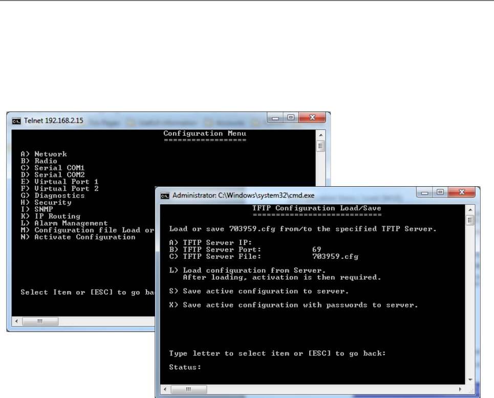
154 Document Number: 0100SM1401 Issue: 12-16
Configuration Save / Load (TUI)
Trivial File Transfer Protocol (TFTP) Client
As of firmware 1.4.0 , radio configuration files can be saved and/or loaded via TFTP. TFTP file saving/loading is available within
the Text User Interface (TUI) only.
In order for a TFTP file transaction to occur, the embedded TFTP client within the radio, requires a connection to an active TFTP
server. TFTP server software is available on the internet, where they can be installed on a PC and operate in the background.
To access the radio’s TFTP client within the TUI, explore to: Configuration -> Configuration file Load or Save
To connect to the TFTP Server, the following parameters are required by the TFTP Client:
TFTP Server IP: Specify the IP address of where the TFTP server resides (the TFTP server can be connected via a radio link
of directly connected to the radio)
TFTP Server Port: Specify the IP port number in which the TFTP server is listening on. (Default: 69).
TFTP Server File: Specify the name of the file being saved/loaded. (Default file name is the serial number of the radio) If the
name is changed from default, only alphanumeric characters, without spaces can be used.
Load configuration from Server: Using the information provided in the previous parameters, the TFTP Client will attempt to:
• Establish a connection with a TFTP server at the specified IP address and port number.
• If a connection is successful, the client will then request from the server, a configuration file to load into the radio (a
previously stored configuration file within the TFTP Server is required). The name of the file requested is that which is
specified within the TFTP server file parameter. Ensure that the spelling and case sense of the file name is correct.
• Once the file is successfully loaded in to the radio, use Escape to browse back to the main menu, to allow activation of
the loaded configuration file.
• Once the configuration file has been activated, if the new configuration contained a different IP address from the
previous configuration and the TUI connection had been established via an IP connection, a new IP connection may
need to be established (i.e. new Telnet session) targeting the new IP address of the radio.
Save active configuration to Server: Save the active configuration file of the radio to the TFTP server specified. The name
of the file saved will be that which is specified within the TFTP server file parameter.
Save active configuration with passwords to Server: Save the active configuration file including secure information of the
radio to the TFTP server specified (for details on saved secure information, see ‘Configuration Save / Load (WUI)). The name
of the file saved will be that which is specified within the TFTP server file parameter.
Part H – Advanced
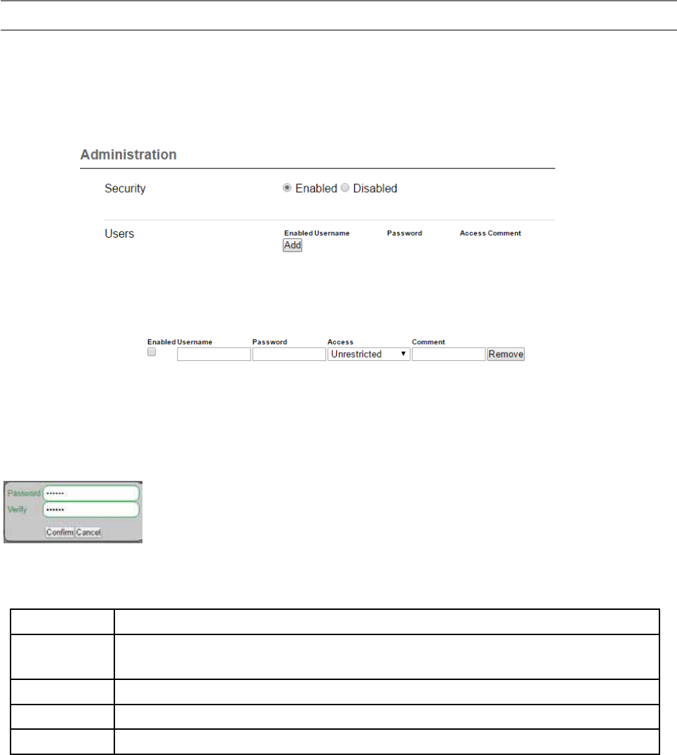
155
Document Number: 0100SM1401 Issue: 12-16
Security
Part H – Advanced
User Administration
Available as of firmware version 1.5.0.
User administration allows an administrator to create individual users with associated levels of radio access privileges.
User administration can be accessed by browsing to: Setup -> Security
Enable ‘Security’ for the access control table to become visible (Security is enabled by default).
To add a new user, select the ‘Add’ button at the bottom of the Users table.
An empty row will be added to the table, with five configurable fields.
Enabled: Check box to enable/disable a user account (without removing it from the table)
Username: The user name can only consist of letters and/or numbers and can be 1 to 30 characters long.
(No two users can have the same user name).
Password: The password can be between 6 and 30 characters long.
• When the password field is selected, a password window will appear.
• The password window prompts for the password to be populated twice, to help ensure that the
characters entered are as expected (if the passwords do not match, a message will appear).
• For security purposes, the password characters are always hidden behind black dots.
Access: Defines the access privilege level for the user being created.
There are four access privilege levels to select from:
Access Privileges
Unrestricted No restrictions to user access
Read/Write/Sec Allows configuration of all items except for user administration
Read/Write Allows configuration of all items except for user administration and security
Read Only Read only
Comment: An optional field for a profile description.
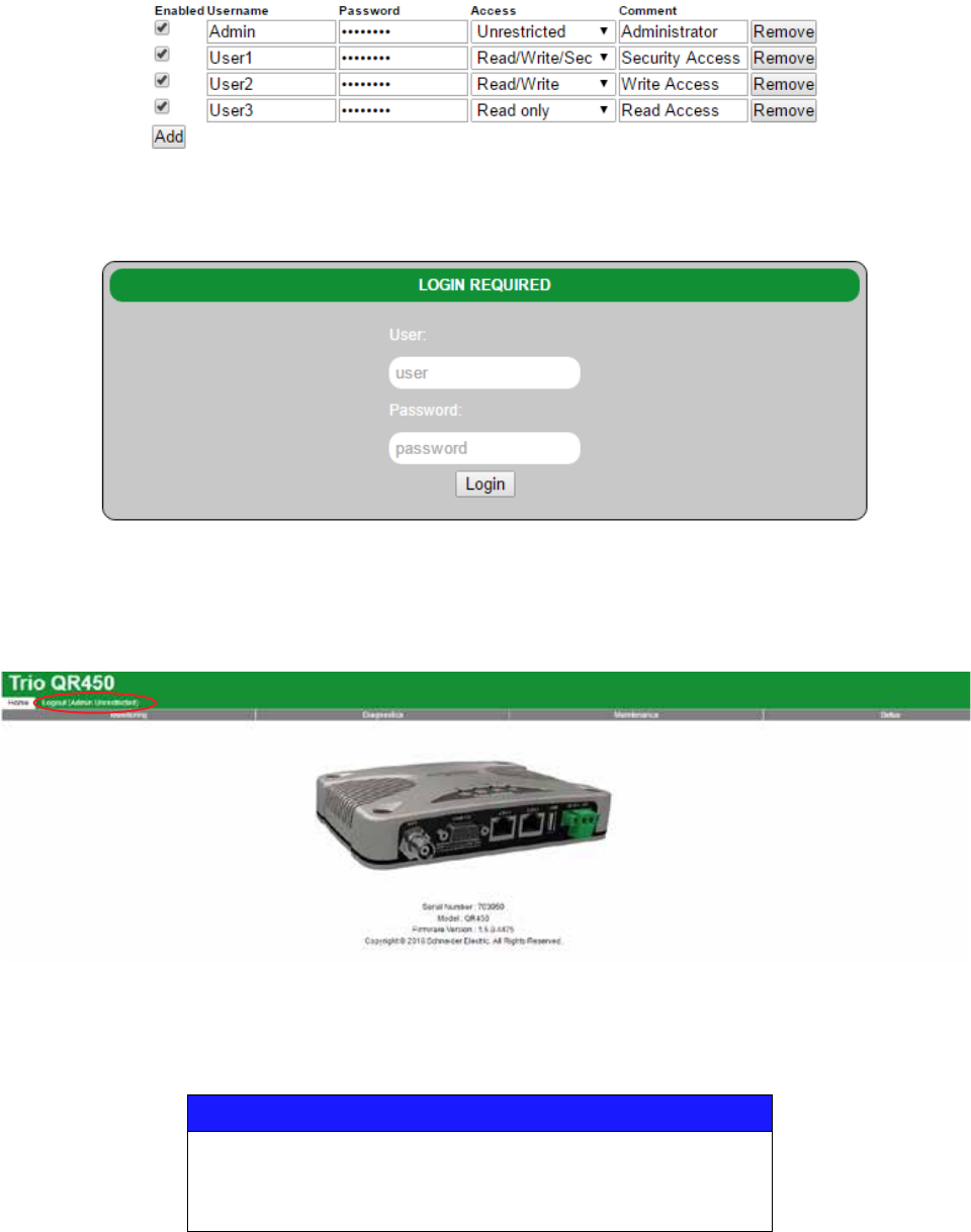
156 Document Number: 0100SM1401 Issue: 12-16
Part H – Advanced
User Administration configuration example:
The following user administration table shows four users configured, one for each priority access level:
Logging in:
Once the configuration is activated, the configuration page will prompt for log in credentials to allow access to the radio:
Enter the log in credentials and select the ‘Login’ button.
If entered correctly, the Home page of the radio will be displayed along with the user name and access level shown within the
page banner (Circled in RED below):
Without log in credentials, users will have access to the radio’s monitoring page, where the radio’s diagnostic information and
basic unit information is available.
NOTICE
POTENTIAL SECURITY RISK
When conguring condential information such as user names and passwords, use a
secure connection to the conguration page such as HTTPS or SSH.
Failure to follow these instructions can result in cyber security vulnerabilities.
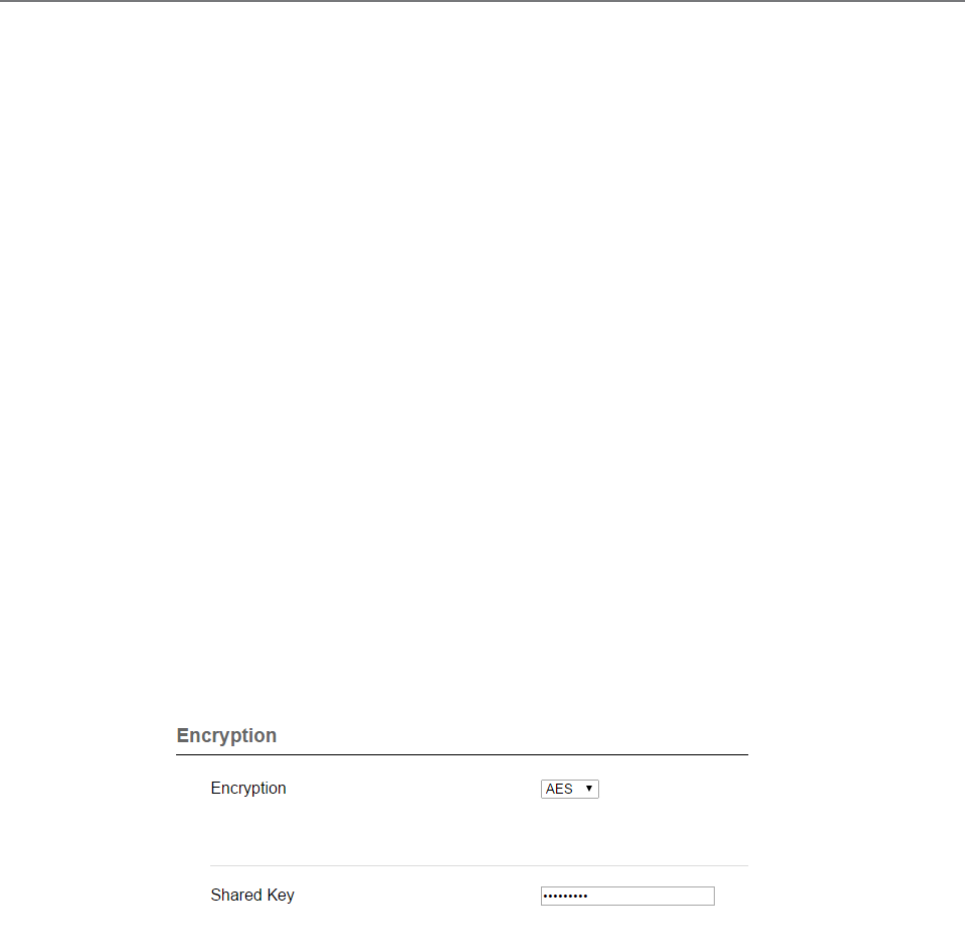
157
Document Number: 0100SM1401 Issue: 12-16
AES Encryption
When encryption is enabled in a network, all data sent over the air is encrypted and can only be read by radios sharing the
same Encryption Key. Encryption must be enabled in each radio in a network. The encryption key is 256 bits long and is
entered as string or a hexadecimal number. For maximum security the chosen key should be one that is difficult for an
intruder to guess.
Once written into the radio using the programmer, it is not possible to read the encryption key so care must be taken to
record the key in a safe place.
Encryption Key: String
For a string type of key, use up to a maximum of 64 printable characters. Observe that the key is case sensitive.
Some examples are:
TRIO2012
Murray River Region
Encryption Key: Hexadecimal Number
Hexadecimal numbers can have a value of 0 to 15 and are represented by 0-9 and A, B, C, D, E or F.
A hexadecimal key begins with 0x and has up to 64 digits following.
Use an even number of hexadecimal digits.
Some examples are:
0x1234
0x123456789ABCDE
0x11111111222222223333333344444444 up to 64 digits
Configuration of AES is done via Setup -> Security
Part H – Advanced

158 Document Number: 0100SM1401 Issue: 12-16
Part I – Installation & Commissioning
Part I – Installation & Commissioning
POWER SUPPLY REQUIREMENTS (QB)
Operating Voltage: 11...30 Vdc (Dual Input)
Input Power (Rx typical): 14 Watts
Input Power (Tx typical): (See table below)
Introduction
All Q data radios need to be properly installed and
commissioned in order to function reliably. Installers should
be familiar with RF products / installations and are equipped
with appropriate tools necessary to help ensure that the
ongoing reliability of a communications system.
This is a short form guide to assist with the correct
installation and commissioning of Q data radios and help
ensure that useful tests are made and recorded at each
site for future reference should an issue arise.
Installers should check that each Q data radio has been
programmed to suit their requirements before installation.
Installations play a role in network performance. The
installation should be performed in a professional
manner with careful consideration to the following items:
1. Adequate primary power cable - relative to the length
of cable to minimise voltage drop.
2. Shielded CAT-5 or CAT-6 Ethernet patch cable between
the Q data radio and any external Ethernet equipment.
3. Shielded RS-232 data cable between the Q data radio
and any external RS-232 equipment.
3. Low loss coax used for antenna feed line.
4. Careful termination of RF connectors.
5. A suitable antenna for the requirement.
6. Suitable placement of the antenna.
7. Adequate signal strength from the master radio.
TYPICAL INSTALLATION OVERVIEW
The following information should assist when installing
and commissioning a Q data radio Ethernet system.
DATA CONNECTION
In industrial environments connection to any external
device should be by shielded CAT-5 or CAT-6 patch
cable. A cables should be routed with strain relief.
MOUNTING
The radio modem should be mounted in a cool, dry, and
vibration free environment. Mounting of the unit should
be in a location providing easy access to mounting screws
and all connections. Q Data radios can operate within a
-40...70°C (-40 to 158°F) ambient environment.
COAX CABLE CONNECTION
Select the appropriate cable and connectors for each
application; selection can impact on the performance of
the system.
As an example, for each 3dB of cable and connector loss,
half the transmitter power is lost and twice the receiver signal
power is required to produce the same RF link performance.
In some installations where strong signals are present,
a compromise of cable and connector cost may be
acceptable.
All connector terminations should be performed as per the
manufacturer’s specifications; and if connectors are to be
used outside, use a sealant such as amalgamating tape to
seal connectors. Acetic cure silicon to seal the connectors
is not advised.
Coax cables should not be stressed by tight bends,
kinking or excessive flexing. Ensure that coax cables have
sufficient strain relief and are secure. If large-diameter
rigid or semi rigid cable is used, it is recommended to
use a short length of high quality RG223 cable between
the unit and main cable feed.
Connect and secure the Antenna, Ethernet and Serial plugs
BEFORE applying power to the unit. Lastly, before inserting
the power plug, re-check that the terminals being used,
polarity and voltage on the DC power plug is correct using a
multimeter and check the power cable against the +/- label
on the power input socket.
POWER SUPPLY REQUIREMENTS (QR)
Rated Operating Voltage: 10...30 Vdc
Input Power (Rx typical): 5 Watts
Input Power (Tx typical): (See table below)
The QR is supplied with a lock-in mating DC power
connector which should be installed with the locking
screws done up tightly (0.5 - 0.6 Nm / 4.42 - 5.31 ftin ).
The radio is designed to limit damage if the voltage
exceeds 30 Vdc or if reverse polarity is applied. The field
replaceable internal fuse has a 7 Amp rating.
In high ambient temperature situations, the internal fans
may operate, resulting in an increase of input power of
up to 28 Watts.
Typical receive/standby input power is 14 Watts. The input
power will vary in transmit mode according to RF output
power level.
The QB is supplied with a lock-in mating DC power
connector which should be installed with the locking
screws done up tightly (0.5 - 0.6 Nm / 4.42 - 5.31 ftin ).
The radio is designed to limit damage if the voltage exceeds
the operating voltage or if reverse polarity is applied. The field
replaceable internal fuse has a 12 Amp rating.
Tx Power (dBm)
Typical Input
Power (Watts)
QB150 QB450
30 26 34
37 38 46
40 46 59
Tx Power (dBm)
Typical Input
Power (Watts)
QR150 QR450
30 18 24
37 28 37
40 39 52
Before proceeding with any wiring to the radio, refer to the
wiring safety noticies within the preface of this document.

159
Document Number: 0100SM1401 Issue: 12-16
Part I – Installation & Commissioning
Where possible, avoid mounting antennas:
1. Against or adjacent to steel structures.
2. In an area which will have intermittent obstructions
- people walking past, vehicles driving past etc. That is,
mount antennas well above such moving obstructions.
3. Near any electrical equipment.
4. Near metal beams, structures etc.
5. Inside any metal enclosures, tin sheds / warehouses
etc. - (Some meshed wire fences act like a “brick wall” to
RF transmissions).
6. Away from guard rails or support beams.
7. Above any pipe work or corrugated iron roofs.
Sometimes installations in such environments are
unavoidable and where this is the case, certain care can
be taken to help ensure a reliable installation.
If tests indicate poor signal strength then the antennas
at one or both ends of the link should be raised, and/
or moved clear of obstructing objects, or if directional
antennas are employed they should be checked
for correct directional orientation and polarisation
(horizontal or vertical signal orientation).
LED Indicators
LED indicators are documented in Part E - Quick
Reference Guide - Hardware of this User Manual.
However, during the installation process check that the
LED indicators are operating correctly.
DC POWER
If all the LEDs are off, no DC power is reaching the radio
modem or the fuse is open. Successful power-up is
indicated by the “Pwr/Tx” LED showing a continuous
GREEN state.
When the transmitter is active the “Pwr/Tx” LED turns
RED.
Sync/No RX LED Indicator
The “Sync/NoRx” LED is used to indicate the state of the
receiver.
A solid or regular flashing GREEN LED shows that the
modem is receiving decodable data.
A solid or flashing RED LED indicates the modem is
receiving un-decodable data, this is typically from an
unwanted source.
ETH port LED Indicators
See the table below for Ethernet port LED indicators.
ANTENNA INSTALLATION
The selection of antennas and their placement can
influence RF link quality.
Antennas are generally mounted to a vertical pole with
either vertical or horizontal polarisation as per the license
requirement.
Antennas should be mounted as high as practical and
away from metal surfaces which can cause reflections.
As a typical generic example for selecting the suitable
antenna type, Point to Multipoint (PTMP) systems
generally employ high gain (3, 6, or 9dB gain) omni
directional antennas at the Entry Point/Repeater
sites and either omni directional whips (unity gain) or
preferably high gain directional yagi antennas (9 or 14dB
gain) at the remote sites.
YAGI ANTENNAS
Yagi antennas not only provide signal gain and directivity,
but also provides protection from interfering signals
which are outside the beam width of the antenna. Yagi
antennas help provide optimum performance when
communicating over very long distances.
Yagi antennas are polarised and need to be mounted
either vertically (elements pointing from the ground to the
sky) or horizontally (elements in parallel with the horizon).
When mounting yagi antennas with vertical polarisation,
it should be noted that some antennas have a drain hole
in the dipole (loop section of antenna). The small drain
hole on one end of the dipole must be pointed towards
the ground so that water will drain out of the antenna.
OMNI DIRECTIONAL ANTENNAS
Omni directional antennas provide a radiation pattern
of equal strength through 3600 in the horizontal plane.
This makes them ideal for Entry Point /Repeater radio
antennas in point to multipoint systems because they
can reach a large populous of remote sites.
Omni directional antennas are also used at remote sites
(although yagi antennas are preferred) and are typically
ground independent whip type antennas. The main
reason for using whips at remote sites is for aesthetics as
they are far less obtrusive than a yagi.
Regardless of the type, antennas need to be mounted
properly and in a suitable location as covered below.
ANTENNA PLACEMENT
Antenna placement is of paramount importance and
plays a big part of the antennas and in turn systems
performance.
When choosing antenna locations the aim is to find
the largest path of unobstructed space and locate the
antennas within that space. Locate the antennas as high
as possible and clear of any obstructions.
ETH1/2 LEDS
Ethernet port inactive, no cable connected
Ethernet port active @ 10Mbps
Ethernet port active @ 100Mbps
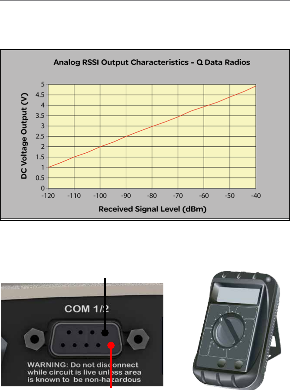
160 Document Number: 0100SM1401 Issue: 12-16
Chart is approximate only.
COM 1/2 - Pin 5 - Signal Ground
COM1/2 - Pin 9 - RSSI Output
Optimising the Antenna for Rx Signal
When using a directional antenna, it will be necessary to align the antenna to achieve optimal received signal. This can be done
using TView+ Diagnostics (measured RSSI) or by measuring the RSSI output on Pin 9 of the serial COM port.
This can be done by using the (0-5Vdc) output on Pin 9 of the serial COM port to indicate signal strength (RSSI). This voltage can
be converted to dBm using the chart below.
The RSSI output will peak latch for 3 seconds.
Part I – Installation & Commissioning
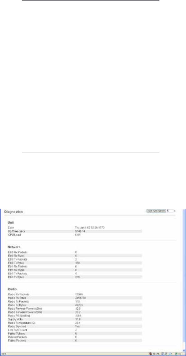
161
Document Number: 0100SM1401 Issue: 12-16
Commissioning
When commissioning an Ethernet radio network, ensure
that the incoming received signal strength (RSSI) is
adequate to provide reliable communications.
In order for a system to operate reliably, an “adequate”
signal level needs to be present which allows for fading
and interference.
An adequate level is typically 20 to 30dB above the
minimum threshold of the receiving device. Using the
dynamic RF data rate can allow the minimum threshold
specification to be taken from the lowest available data
rate of the bandwidth being used.
Should this level not be achieved, then either;
1. A more suitable location to mount the antenna.
2. The antenna will need to be mounted higher in a more
prominent location to achieve as close as possible to
clear line of site.
HTML Diagnostics
Overview
After the Q data radios have been configured and installed,
the next step in the commissioning process is to review
the HTML diagnostics available in every radio. Diagnostic
parameters available are shown in the image below:
Unit Specific:
Date: Specifies the current date and time. For the
date and time to be correct the radio needs
to be configured to synchronise with a NTP
Time Server.
CPU Load: Specifies the amount of CPU load the
linux based kernel is experiencing.
Network Specific:
ETH 1 Rx Packets: The number of Ethernet packets
received on ETH1.
ETH 1 Rx Bytes: The number of bytes received on
ETH1.
ETH 1 Tx Packets: The number of Ethernet packets
transmitted on ETH1.
ETH 1 Tx Bytes: The number of Ethernet packets
received on ETH1.
(The same applies for ETH2)
Radio Specific:
Radio Rx Packets: The number of packets received by
the radio.
Radio Rx Bytes: The number of bytes received by the
radio.
Radio Tx Packets: The number of packets transmitted
by the radio.
Radio Tx Bytes: The number of bytes transmitted by
the radio.
Radio Reverse Power (dBm) : TX Reverse power
measured in dBm.
Radio Forward Power (dBm): TX Forward power
measured in dBm.
Radio RSSI (dBm): The RSSI (Received Signal
Strength Indicator) measured in dBm.
Supply Volts: The DC supply voltage measured in dBm.
Radio Temperature (C): The internal radio
temperature measured in degrees Celsius.
Retired Packets: The number of packets that were
discarded after ARQ retries and time outs
were exhausted.
Failed Packets: The number of incoming packets
that have failed CRC check and have been
discarded.
Part I – Installation & Commissioning

162 Document Number: 0100SM1401 Issue: 12-16
Part J – Firmware Updating and Maintenance
Firmware Updating
Introduction
Schneider Electric work towards providing enhancements and improvements to the firmware for the Q data radios. It is
recommended that you keep the Q data radios up to date with the latest firmware releases.
The following instructions can be used to upgrade firmware in any Q Data Radio.
Using a standard web browser you can connect to a Q data radio and inspect the current firmware version which is displayed on
the home page of the Web User Interface.
For new firmware updates which may be beneficial to your system, check the Schneider Electric web site:
http://www.schneider-electric.com/
To access the Trio radio section of the website, browse to: Products -> Automation and Control -> Telemetry and Remote
SCADA Systems.
Download the firmware pack from the website and store it on your PC or in a location on your computer network which can be
accessed during the firmware update process.
Firmware updates can be performed on a unit connected locally to the PC or remotely via an operational radio link. For a local
upgrade, it is recommended that all other cabling to the unit be disconnected prior to commencing the firmware update to
minimise any interruption to the process or disturbances of signals on cables still connected.
For remote upgrades, it is advised to use the global firmware update tool.
The firmware update process is two part. First, the firmware is transferred from the PC to the Q data radio alternate firmware
image via the HTML browser. This is called “uploading and unpacking” the firmware. This typically takes several minutes. The
second process involves the user activating the alternate firmware pack, which causes the radio to swap current firmware
with the alternate, and re-boot. This typically takes between 5 to 6 minutes, depending on how much firmware needs to be
updated.
Firmware is distributed inside a ZIP file that contains a full firmware image as well as patch files. Patch files contain only
the differential set of changes based between two specific firmware versions, hence they are smaller and take less time to
transmit over the air than a full firmware file.
Full firmware images should be applied when locally firmware upgrading the radio. Patch files are designed for use with the
global firmware upgrade software tool (see below), which automatically inspects the target radios current firmware version
and chooses the correct patch file to send. Patch files can also be loaded manually via the firmware upgrade page in the web
browser, however the correct patch file needs to be manually selected.
Both full and patch file methods only apply changes to the alternate firmware pack. Once the changes are applied, a separate
user initiated process will activate the alternate firmware pack. This activation can be done both via the web page interface
and via the global firmware upgrade software tool.
Part J – Firmware Updating and Maintenance
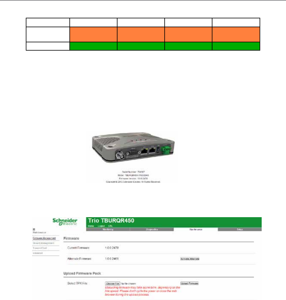
163
Document Number: 0100SM1401 Issue: 12-16
Firmware Updating and Factory Default Information LEDs
In some circumstances a firmware update or factory default might be required. A special LED sequence is shown during this phase.
COM 1 RxD / TxD COM 2 RxD / TxD Sync / RxSig Pwr / Tx
Firmware
upgrade
Amber Amber Amber Amber
Factory Defaults Green Green Green Green
Firmware Upgrade: All LEDs flash AMBER (as shown in table above) - 1 second ON and 1 second OFF
Factory Default: (as shown in table above) will first illuminate all LEDs to a solid green state to indicate a factory default
process has been initiated. Once the factory default process has begun, the LEDs will begin a sequence of flashing green
LEDS until the process has been completed.
1. Click on the ‘Maintenance’ button located along the top of the page.
2. Select the ‘Firmware Management’ button along the left hand side of the page. The firmware upload page will now be
displayed as shown below.
Firmware Update Procedure
Ensure that an Ethernet cable is connected from the PC’s LAN port to an Ethernet port of the Q data radio, and the unit’s IP
address is entered into the web browser. Check the serial number displayed in the HTML page against the Q data radio that you
are about to update. The serial number can be found in center of the home page as shown across the page.
3. To select the new firmware pack you wish to upload, click on the Browse/Choose File button.
4. Locate the .tpk file which contains the new firmware. Select the file and click on “Open”. The page should now display the name of
the tpk file chosen in the upload firmware pack section.
5. Click the ‘Upload Firmware’ button. If there is an existing firmware pack located in the Alternate Firmware section, the
radio will display a message, indicating that the alternate pack is about to be over written by the new firmware pack. Click OK
to continue.
6. This process can take up to 10 minutes, wait until the new firmware pack is displayed within the Alternate Firmware
section.
7. Once the firmware has successfully uploaded and unpacked in to the alternate firmware location, click the ‘Activate
Alternate’ button.
8. During this phase, all 5 LED indicators will flash amber simultaneously. After 4 to 5 minutes the Q data radio will re-boot
and the new firmware will be activated.
After a successful activation, the new firmware pack should be displayed within the ‘Current Firmware’ section.

164 Document Number: 0100SM1401 Issue: 12-16
Introduction
The TView+ Management Suite software provides a facility to perform Global firmware updates to every Q data radio within a network
over the RF channel. The Global firmware update facility uses two techniques to limit the impact on user data. For instructions on
installing TView+ Management Suite, refer to the TView Diagnostics User Manual.
1. Data rate-limiting which trickles the data onto the RF channel at 5% of the channel capacity.
2. Differential firmware packs (patch files) dramatically reduce the size of the file needed to be sent over the RF channel.
The combination of these two features allows seamless operation of SCADA traffic while the update is in progress.
The firmware upgrading tool is rate-limited to minimise impact on user data. The uploading process will take some time. Allow
up to 24 hours to complete.
Minimum Programmer Requirements
TView+ Programming software Version 3.25.0 (Build 19) onwards.
(It is recommended to upgrade to the latest version of TView+ Programming software).
Connection
Ethernet connection between the PC and the ETH port of the entry point radio. This tool distributes firmware to the
broadcast address of a subnet. If network routers/layer 3 switches/Firewalls or MAC layer filters are located on the Ethernet
connection between the PC and the entry point radio, ensure that broadcast packets are not being blocked/prevented to
allow the tool to work.
Global Firmware Updating
Part J – Firmware Updating and Maintenance
IP Routing Mode
When targeting the network address of the radio network while in IP routing mode, the radio WAN subnet is used.
As the entry point radio is operating as an IP router, a configuration to allow broadcast packets to pass is required.
Within Setup -> IP Routing -> Advanced, enable the parameter ‘Directed Broadcast’. This will allow directed broadcasts
between LAN/WAN.
Repeating Broadcast Messages
Within an IP Routing mode radio topology which includes a repeater, a configuration to repeat broadcast messages is required.
Within Setup -> IP Routing -> Advanced, enable the parameter ‘Forward Broadcast’. This will allow forwarding of broadcasts
received on the WAN back on to the WAN.
Ethernet Filtering
As the global firmware upgrade tool sends broadcast packets as a means of reaching each remote radio, ensure that Ethernet
filtering is not enabled within the entry point radio, which would prevent the firmware upgrade broadcasts from being sent on to
the radio channel.
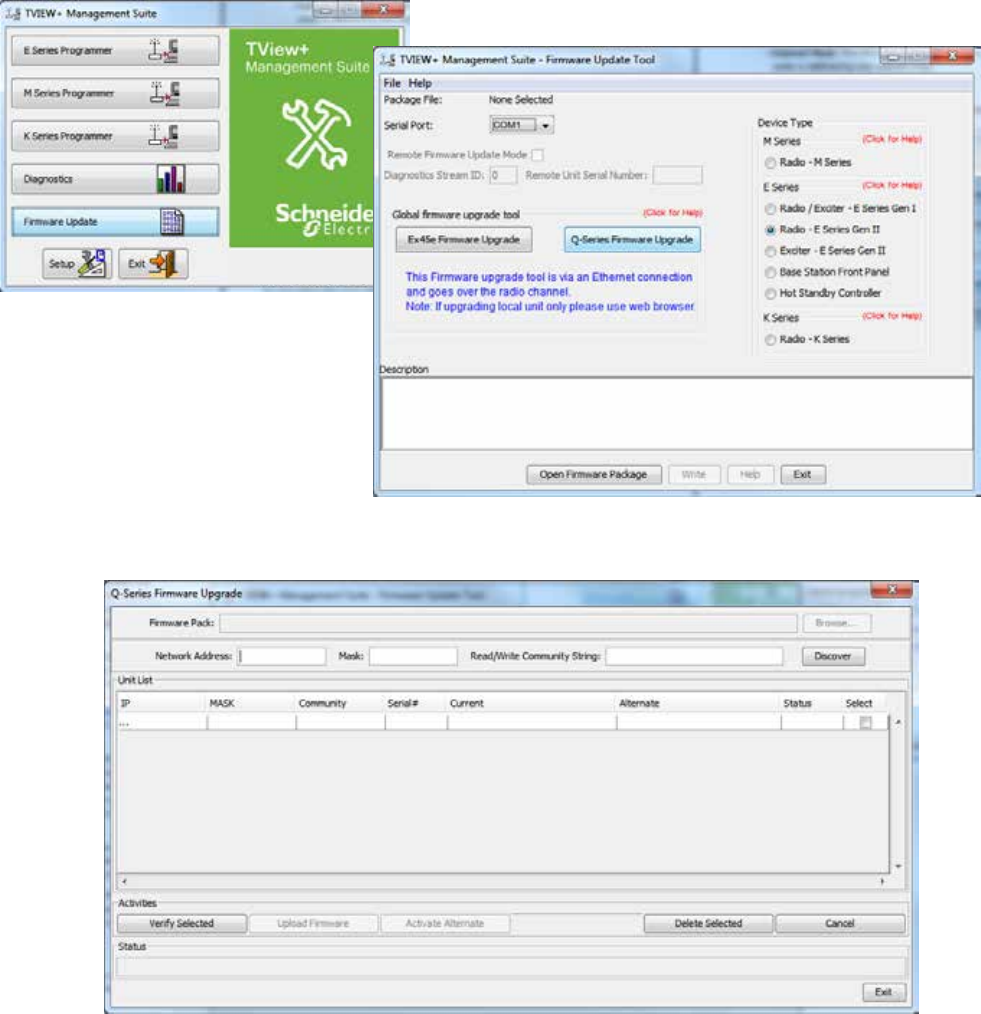
165
Document Number: 0100SM1401 Issue: 12-16
2) Open the Firmware Upgrade Tool: Open TView+ Management Suit, select the ‘Firmware Update’ button. This will open the
Firmware upgrade page. Once open, select the ‘Q-Series Firmware Upgrade’ Button. This will open the Global Firmware Upgrade tool
for Q-Series.
This will open the Global firmware upgrade tool.
Step by step instructions
1) Radio Pre-Configuration: Before performing a global firmware upgrade, ensure that each radio being upgraded has been pre-
configured with the following common settings:
• SNMP: The firmware upgrade tool utilises the SNMP protocol, therefor, each radio requires the following pre-configuration:
- SNMP Enabled:
- SNMP Version: V1 or V2c
- Read/Write Community String: (default sting is: private)
• Mask: The firmware upgrade tool will address packets to the radio network’s broadcast address. The broadcast address of a
radio is defined by the subnet mask.
Part J – Firmware Updating and Maintenance
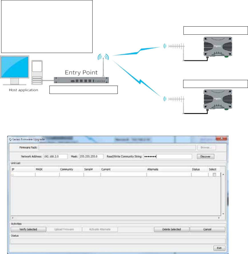
166 Document Number: 0100SM1401 Issue: 12-16
2) Configure the Firmware Upgrade Tool: The firmware upgrade tool requires the following parameters to allow communication
with each of the radios being upgraded.
- Network Address: This parameter defines the base (beginning) IP Address of the subnet. Otherwise known as
Subnet IP, Base Address or Subnet ID.
For information on how to determine what the network address of your radio system is, see your network
specialist or refer to a network calculator such as the one found at this address: (http://ipcalc.nmonitoring.com/).
- Mask: The mask is used to define the range of the subnet. Used in conjunction with the Network Address, the firmware
upgrade tool can determine:
- Where the subnet starts
- How many IP addresses are within it
- Where the Subnet ends (The last address within a subnet is always allocated as the broadcast address)
- Read/Write Community String: Set the same Read/Write Community String within all of the target radios.
Example - Configuring the Firmware Upgrade tool: The diagram below shows a typical PTMP system along with the
configuration parameter values required by the Firmware Upgrade tool.
Remote A - 192.168.2.17
Common Radio Settings:
Network Settings:
Subnet Mask: 255.255.255.0
SNMP
SNMP Enabled
Version: 2C
Read/Write Community String: private
Remote B - 192.168.2.18
Entry Point - 192.168.2.16
The Network Address, Mask and Read/Write Community String have been configured to reflect the radio diagram above.
Part J – Firmware Updating and Maintenance
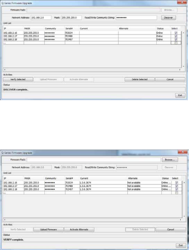
167
Document Number: 0100SM1401 Issue: 12-16
3) Radio Discovery: Once the firmware upgrade tool has been configured with the Network Address, Mask and SNMP Read/Write
Community string of the radio network, the radios can be discovered, and can populate the table. There are two methods for radio discovery:
• Auto Discovery: By selecting the ‘Discover’ Button, the tool will automatically interrogate each IP address within the Subnet
range defined by the mask. If any devices are discovered during this process, the table will be automatically populated upon
discovery completion. Depending on how big the sub net is (how many IP address the tool needs to interrogate) this can take a
long period of time to complete. During this time, the progress is shown at the bottom of the window.
• Manual Population: When a small number of remotes have known IP addresses, it can be time efficient to manually populate
the table (rather than waiting for the tool to interrogate an entire subnet). To perform a manual table entry:
- Within the Unit List, click inside the white blank box underneath ‘IP’
- Enter the IP address of a radio, along with the Mask and Community String.
- A new row will appear for an additional unit (if required) this will continue to happen after every IP address added to the list.
4) Radio Verification: Once the unit list table has been populated (automatically or manually) select the radios which are to be
included in the firmware upgrade by checking the select box at the end of the corresponding radios table entry row.
Once the required radios are selected, click the “Verify Selected” button. This begin an SNMP polling cycle to each of the selected
radios. The poll cycle will occur every 15 minutes, with 4 seconds between each selected radio. This will verify that each of the selected
radio are still present and are able to receive the firmware upgrade broadcasts. To stop the polling or to select a different group of
radios, select the cancel button.
If at any time, a radio needs to be removed from the Unit List table, select the radio in the table and select the ‘Delete Selected Button’.
Part J – Firmware Updating and Maintenance
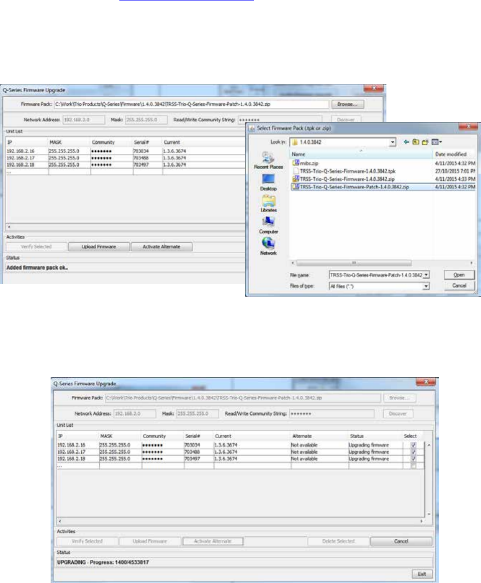
168 Document Number: 0100SM1401 Issue: 12-16
5) Open Firmware: Once the verification process is complete, open the new firmware pack into the firmware update tool.
During a firmware update, only a small patch file is applied to each radio. These patch files only contain the differences
between current operating firmware and the new firmware being upgraded to.
This provides the benefit of only sending small amounts of data over the radio channel, rather than an entire firmware pack. As
it is possible to have radios within the same network operating on different firmware packs, a number of different patch files
may be required to be sent over the radio channel.
This means, during a global firmware update, the firmware update tool requires all firmware update patches at once. This is
done by providing the tool with the global firmware zip package (contains all firmware update patches).
The global firmware zip package is contained within the standard Q Data Radio firmware zip, which can be downloaded from
the Schneider Electric website: http://www.schneider-electric.com/
6) Upload Firmware: Once the Firmware Pack is selected, the firmware can be uploaded to the selected radios.
Select the ‘Upload Firmware’ button. As the uploading is rate-limited to minimise impact on user data, the uploading process
will take some time. Allow up to 24 hours, per patch file being broadcast, to complete.
Part J – Firmware Updating and Maintenance
To open the global firmware zip file within the tool, click the ‘Browse...’ button and select the firmware upgrade zip package.
The global firmware update tool will then select the appropriate patch within the zip file for each radio within the unit list based
one each current firmware pack.
To access the Trio radio section of the website, browse to: Products -> Automation and Control -> Telemetry and Remote
SCADA Systems.
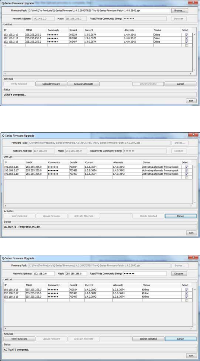
169
Document Number: 0100SM1401 Issue: 12-16
7) Activate Firmware: After the Upload process is complete, the new firmware will be loaded into each selected radios
alternate firmware location.
To activate the alternate firmware (which will switch the current and alternate firmware) select the radios requiring an
alternate firmware activation, and select the ‘Activate Alternate’ button. The status column of the radios selected will display
an active alternate firmware activation.
Once completed, the new firmware will be shown in the current firmware column as shown below.
Part J – Firmware Updating and Maintenance
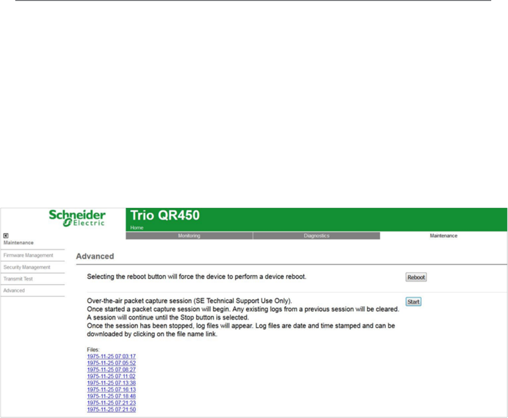
170 Document Number: 0100SM1401 Issue: 12-16
Over-the-air packet capture session (SE Technical Support Use Only)
To assist with support, the radio can capture and record data packets being transmitted/received over the radio channel.
Reviewing this capture can help determine whether there is unwanted traffic being sent over the radio channel.
The packet capture files which are logged are encrypted and can only be reviewed by Schneider Electric technical support.
The use of this tool will generally be requested from the technical support team.
The over-the-air packet capture session can be accessed in the WUI by browsing to: Maintenance -> Advanced.
To start the packet capture process, press the ‘Start’ button. Once started a packet capture session will begin. Any existing
logs from a previous session will be cleared. A session will continue until the Stop button is selected.
To stop the packet capture session, press the ‘Stop’ button. Once the session has been stopped,, the captured log files will
appear. Log files are date and time stamped and can be downloaded by clicking on the file name link.
A log file’s size is limited to 1MB each, and a maximum of ten Logs can be stored per session. Once the maximum number of
logs has been reached, the session will continue by over-writing the oldest log.
As log files are stored within the local radio, over the air retrieval may take some time depending on channel bandwidth and
utilization (up to/and 1MB chunks for multiple files in session capture)
Part J – Firmware Updating and Maintenance
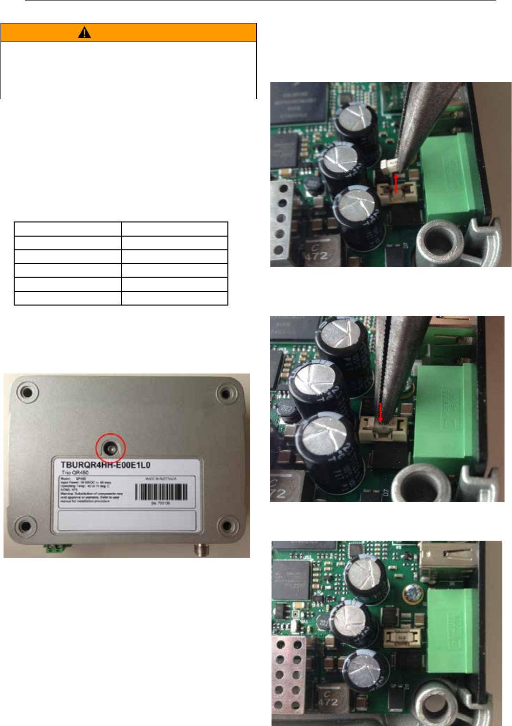
171
Document Number: 0100SM1401 Issue: 12-16
Fuse Replacement - QR
• Fit the new Fuse. Using a pair of pliers and sit the
fuse straight across the top of the fuse holder as
per below diagram.
To access the internal fuse of the QR, remove the lid. In
order to remove the lid, remove the single 2.5mm hex
head screw from underneath the unit.
The fuse in a QR in not soldered into place. Instead it is
mounted within a fixed fuse holder.
To replace the fuse, the following instructions should be used.
• Remove the blown fuse. Remove the fuse using a pair
of pliers and lifting upwards, as per below diagram.
• Then, push down on to the centre of the fuse until
it clicks down into place within the fuse holder.
Part J – Firmware Updating and Maintenance
QR450 Fuse Specification:
Schneider Electric part number: TBUMPWR-FUSE-QR
Specified type fuses are: Littelfuse part numbers 0453007.MR,
0453007.NR, 0453007.MRSN and 0453007.NRSN.
Current rating: 7A
Fuse type: Fast Acting
These fuses can be obtained from the following suppliers.
Supplier Part Number
Farnell 1677444
Element 14 1677444
Digikey F3140TR-ND
Mouser 576-0453007.MR
Newark 20C2978
WARNING
HAZARD OF FIRE
Where an internal fuse is to be replaced, the replacement fuse must be of the
specied type and current rating. Refer to fuse replacement instructions within the
product user manual before servicing.
Failure to follow these instructions can result in death or serious injury.
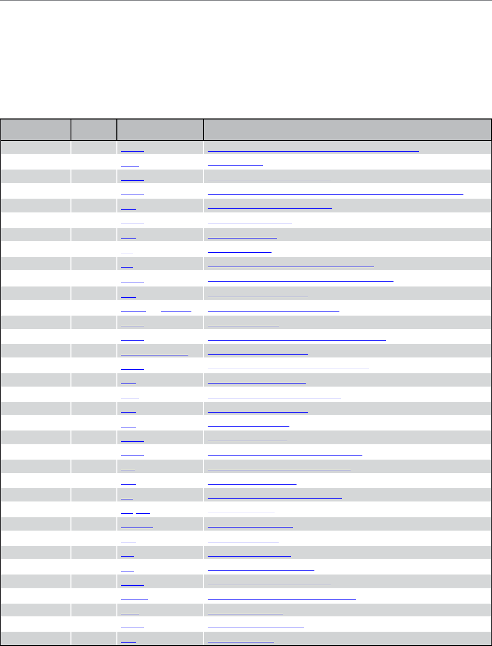
172 Document Number: 0100SM1401 Issue: 12-16
Part K – Open Source License Acknowledgements
CGIC, copyright 1996-2011 by Thomas Boutell and Boutell.Com, Inc. Permission is granted to use CGIC in any application,
commercial or noncommercial, at no cost. HOWEVER, this copyright paragraph must appear on a “credits” page accessible in
the public online and offline documentation of the program.
Modified versions of the CGIC library should not be distributed without the attachment of a clear statement regarding the
author of the modifications, and this notification may in no case be removed.
Modifications may also be submitted to the author for inclusion in the main CGIC distribution.
Component Version License Website
arping 2.09 GPLv2 http://www.habets.pp.se/synscan/programs.php?prog=arping
avahi 0.6.29 LGPL http://avahi.org/
bash 4.2 GPLv2 https://www.gnu.org/software/bash/
bridge-utils 1.4 GPLv2 http://www.linuxfoundation.org/collaborate/workgroups/networking/bridge
bsdiff 4.3 BSD http://www.daemonology.net/bsdiff/
busybox 1.20.2 GPLv2 http://www.busybox.net/
bzip2 1.0.6 BSD http://www.bzip.org/
curl 7.21.7 MIT http://curl.haxx.se/
dropbear 0.53.1 MIT https://matt.ucc.asn.au/dropbear/dropbear.html
ethtool 2.6.37 GPLv2 https://www.kernel.org/pub/software/network/ethtool/
expat 2.0.1 BSD http://expat.sourceforge.net/
gettext 0.16 GPLv2 and LGPLv2+ https://www.gnu.org/software/gettext/
hostapd 0.7.3 GPLv2 http://w1.fi/hostapd/
iptables 1.4.11.1 GPLv2 http://www.netfilter.org/projects/iptables/index.html
libcgic 205 CGIC Basic License http://www.boutell.com/cgic/
libdaemon 0.14 GPLv2 http://0pointer.de/lennart/projects/libdaemon/
libffi 3.0.9 BSD https://sourceware.org/libffi/
libiconv 1.13.1 LGPL https://www.gnu.org/software/libiconv/
libnet 1.1.2.1 BSD http://libnet.sourceforge.net/
lighttpd 1.4.29 BSD http://www.lighttpd.net/
Linux Kernel 2.6.38 GPLv2 https://www.kernel.org/
lzo 2.05 GPLv2 http://www.oberhumer.com/opensource/lzo/
makepasswd 0.5.1 GPL https://github.com/khorben/makepasswd
net-snmp 5.7.1 BSD http://www.net-snmp.org/
ncurses 5.9 MIT https://www.gnu.org/software/ncurses/
ntp 4.2.8 MIT/BSD http://www.ntp.org/
openssl 0.9.8za OpenSSL https://www.openssl.org/
pcre 8.13 BSD http://www.pcre.org/
python 2.7.2 PSF https://www.python.org/
pyserial 2.5 PSF http://pyserial.sourceforge.net/
socat 1.7.1.3 GPLv2 http://www.dest-unreach.org/socat/
u-boot 2011-12 GPLv2+ http://www.denx.de/wiki/U-Boot/WebHome
uClibc 0.9.31 LGPL http://www.uclibc.org/
wpa_supplicant 0.6.10 GPLv2 http://w1.fi/wpa_supplicant/
zlib 1.2.5 BSD http://www.zlib.net/
Part K - Open Source License Acknowledgements

173
Document Number: 0100SM1401 Issue: 12-16
Part L - Support Options
Part L – Support Options
When e-mailing questions to our support staff, make sure you tell us the exact model number (and serial number if
possible) of the Trio equipment you are working with. Include as much detail as possible about the situation including radio
configuration files and system diagrams, also any tests that you have done which may help us to better understand the issue.
If possible, include your telephone contact information should we wish to further clarify any issues.
Technical Support: The Americas, Europe, Middle East, Asia
Available Monday to Friday 8:00am - 6:30pm Eastern Time
Toll free within North America: 1-888-226-6876
Direct Worldwide: +1-613-591-1943
Email: SupportTRSS@schneider-electric.com
Technical Support: Australia
Inside Australia: 1300 369 233
Email: au.help@schneider-electric.com
© 2016 Schneider Electric. All rights reserved. Schneider Electric is a trademark owned by Schneider Electric Industries SAS
or its affiliated companies. All other trademarks are the property of their respective owners - December 2016.
Document number 0100SM1401
Manufactured by Trio Datacom Pty Ltd
(a wholly owned company
of Schneider Electric)
415 Legget Drive, Suite 101,
Kanata, Ontario, K2K 3R1, Canada
Printed in Canada