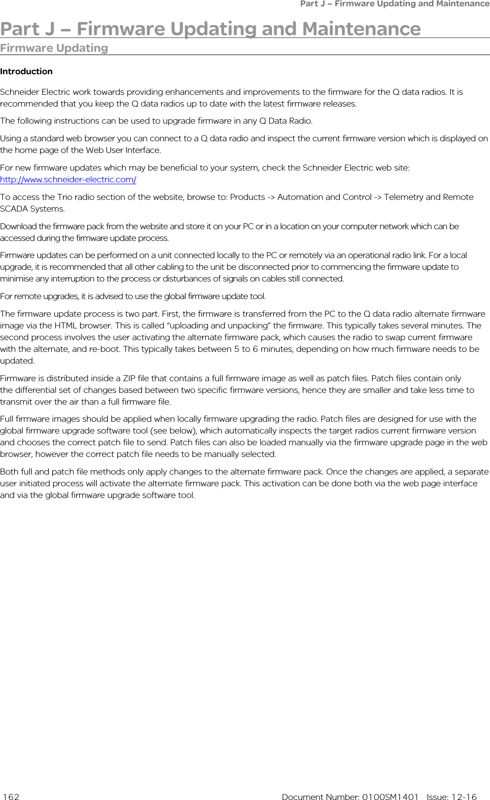
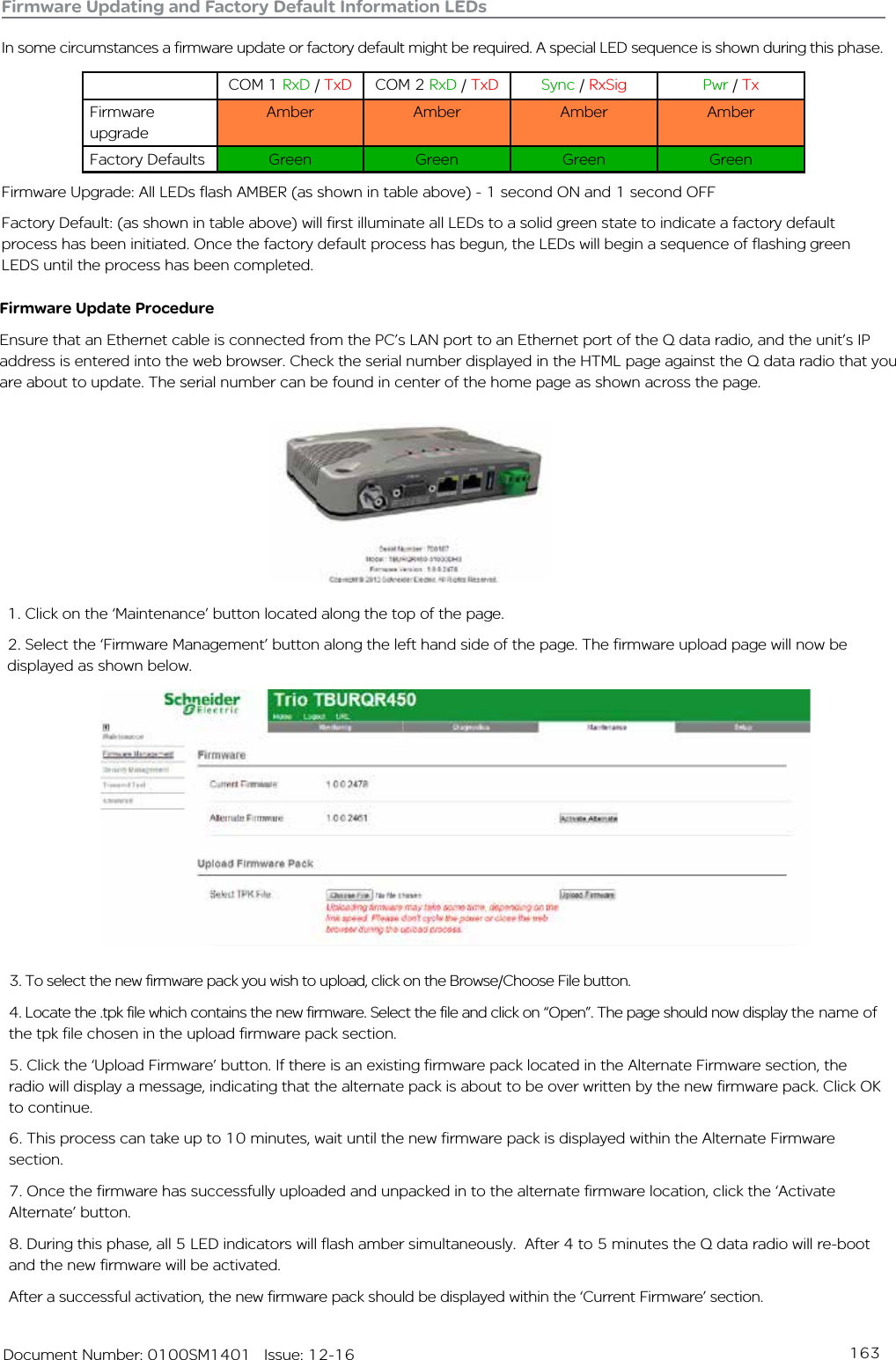
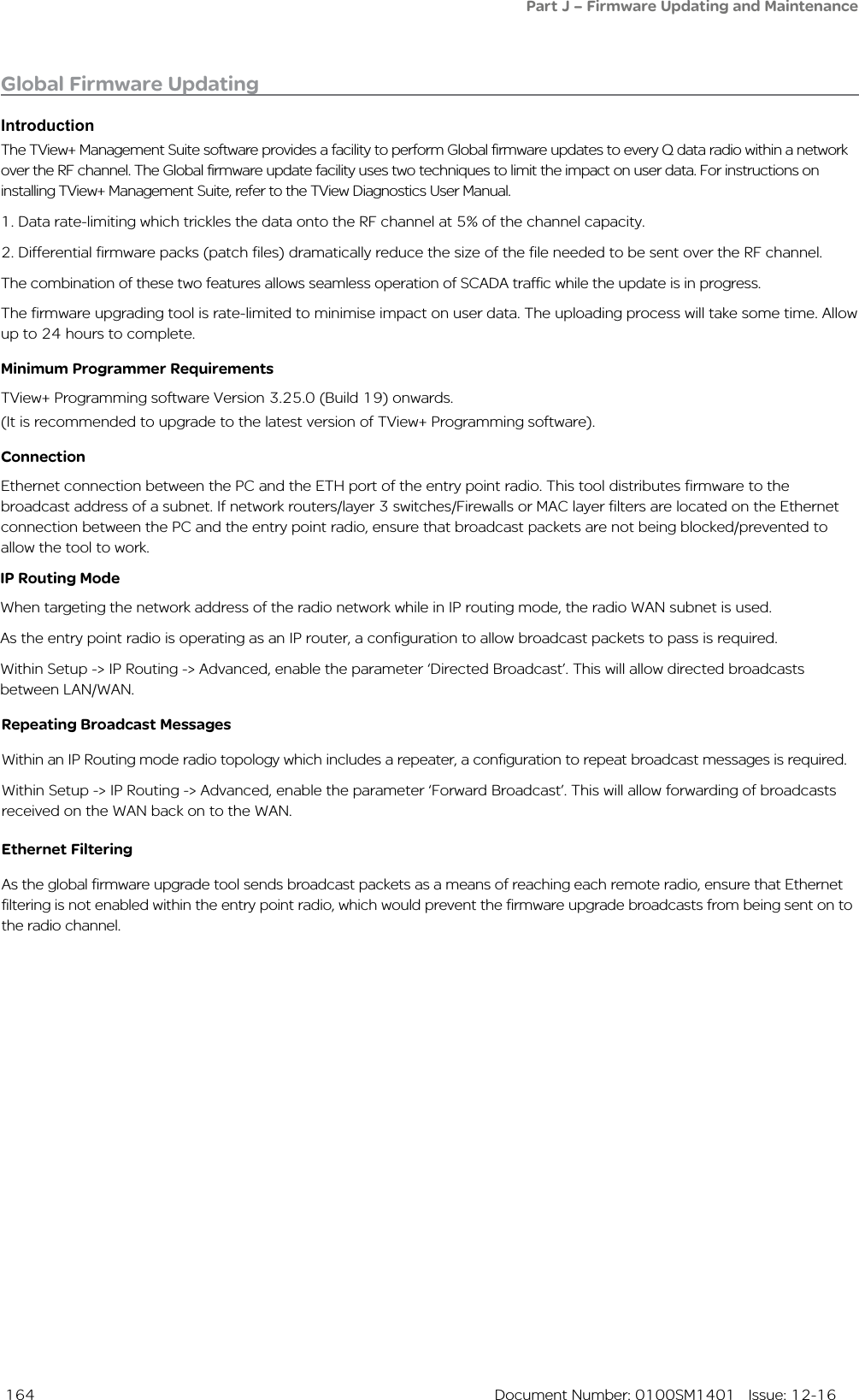
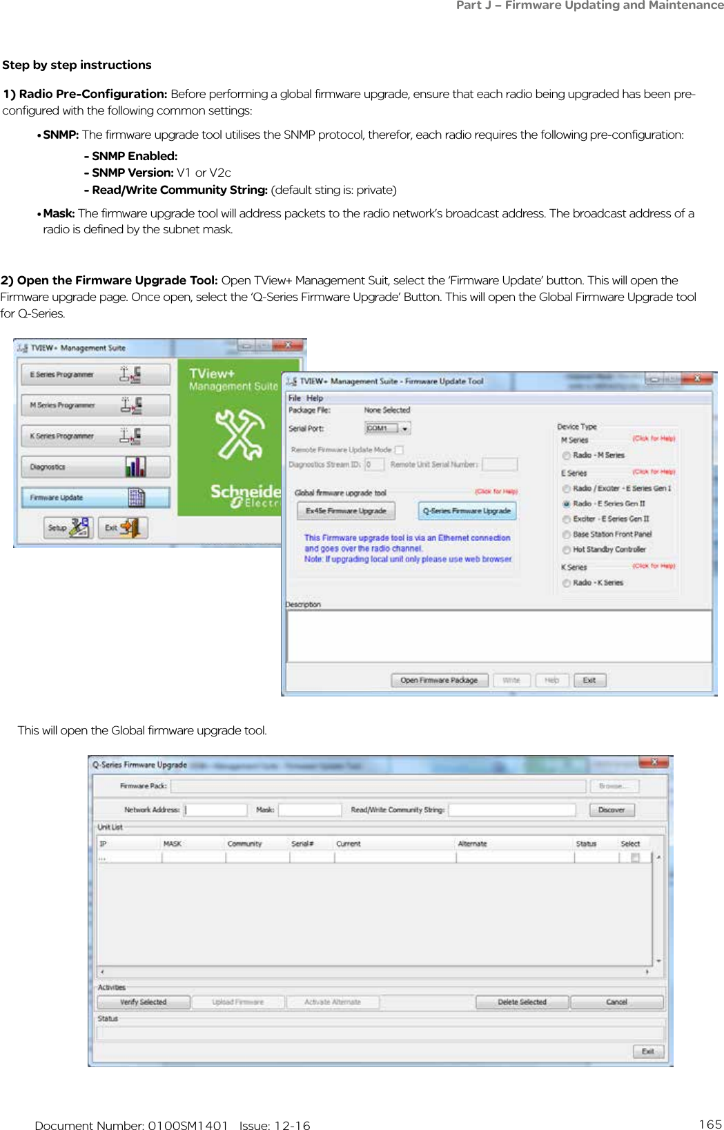
Schneider Electric Systems Canada QR150 VHF remote data transceiver User Manual
Trio Datacom Pty Ltd (a wholly owned company of Schneider Electric) VHF remote data transceiver
UserManual.wiki
>
Schneider Electric Systems Canada
>
QR150 User Manual
User Manual
Navigation menu
Upload a User Manual
Namespaces
Wiki Guide
HTML
PDF
Info
Views
User Manual
Discussion / Help
Navigation
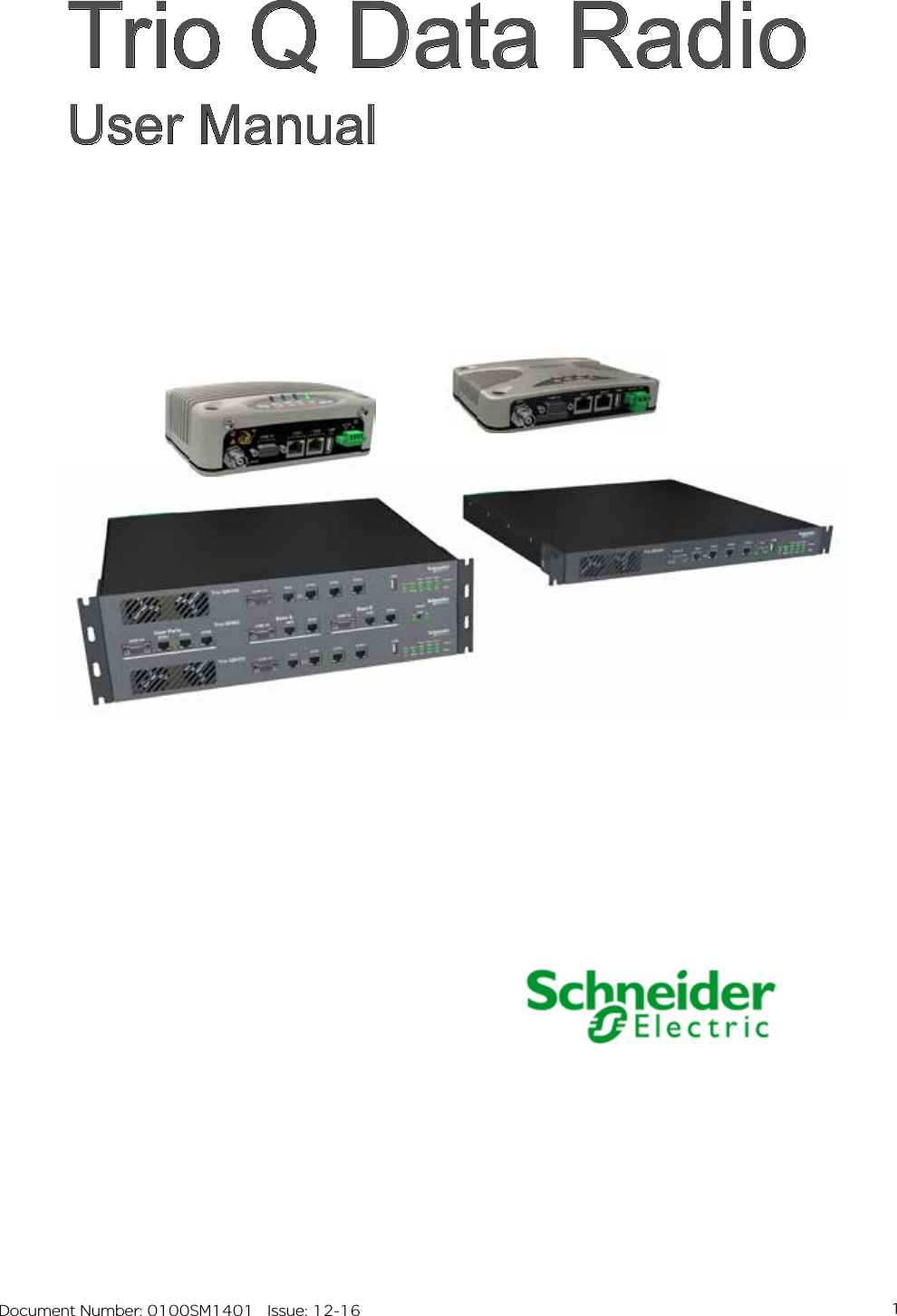
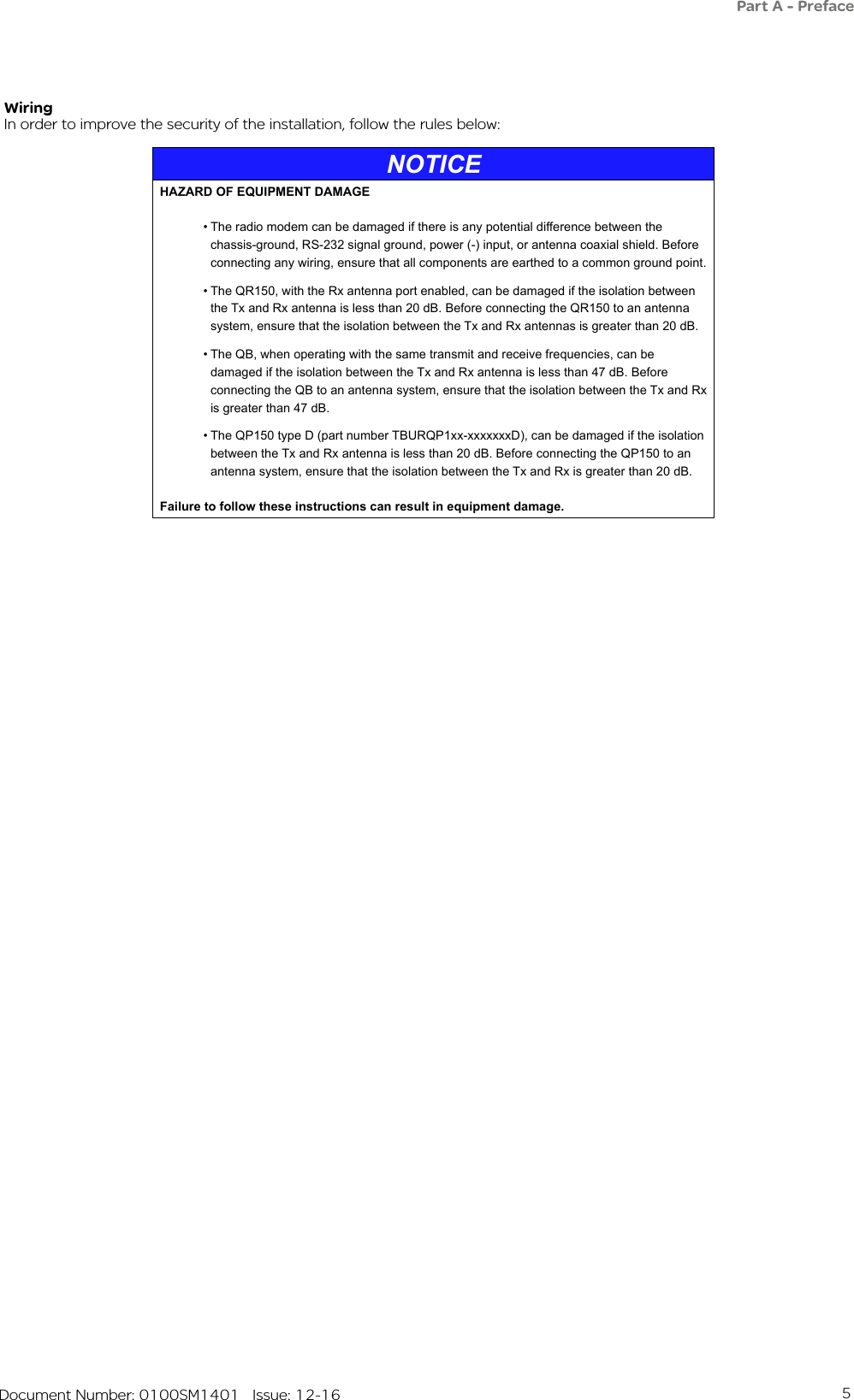

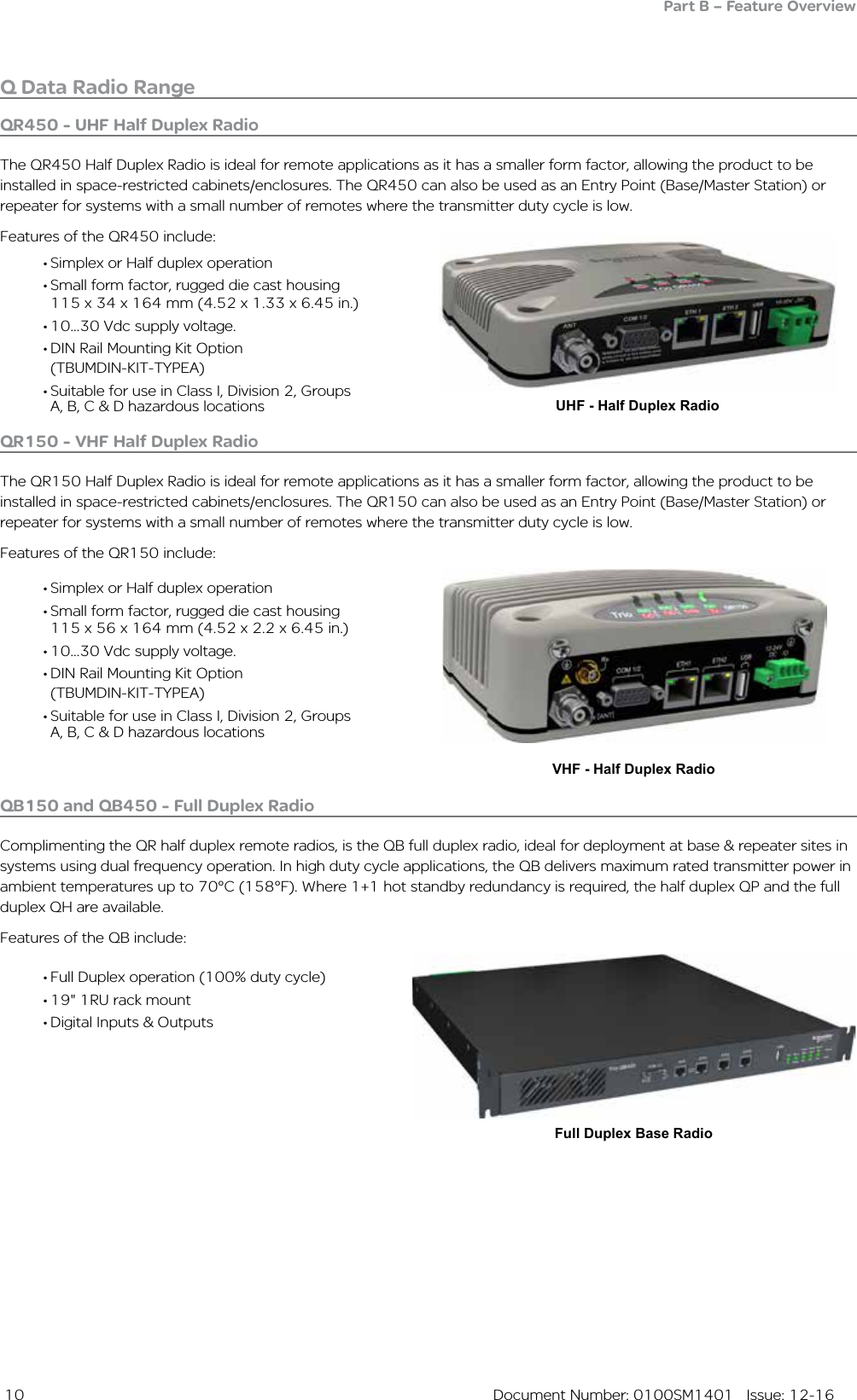
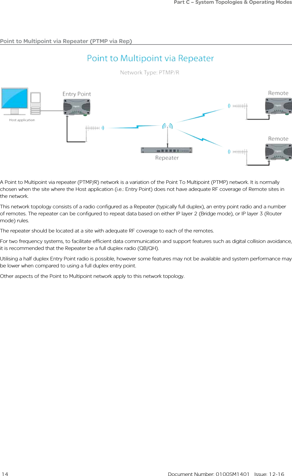

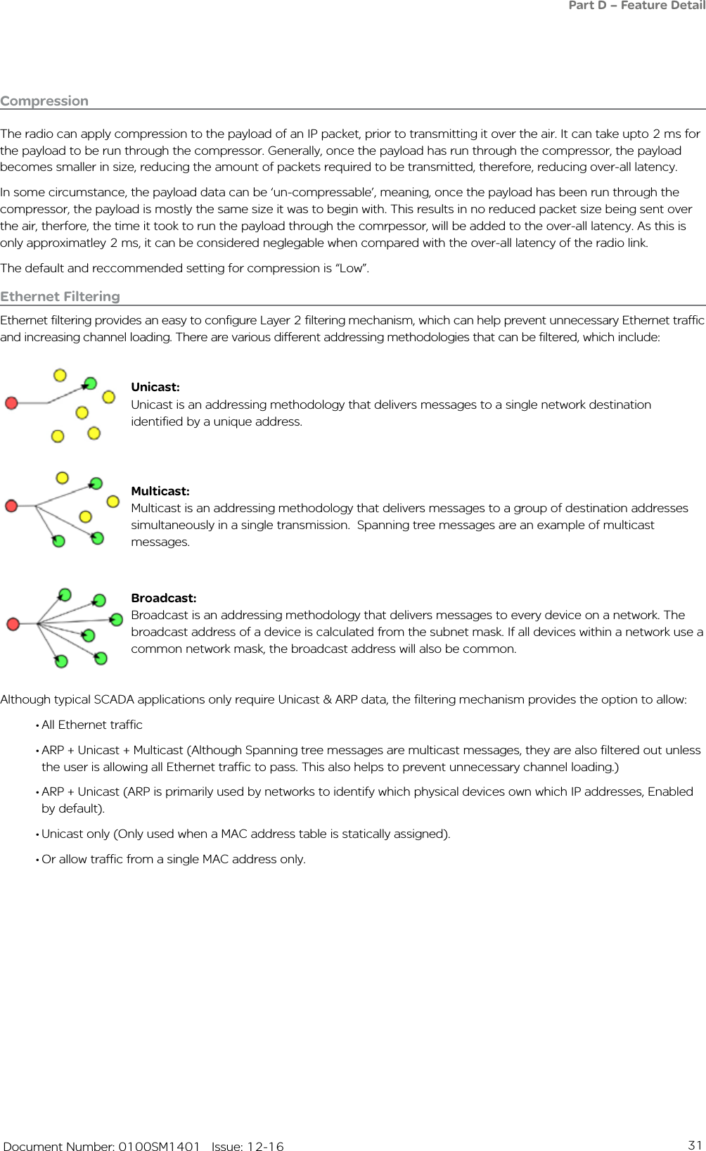
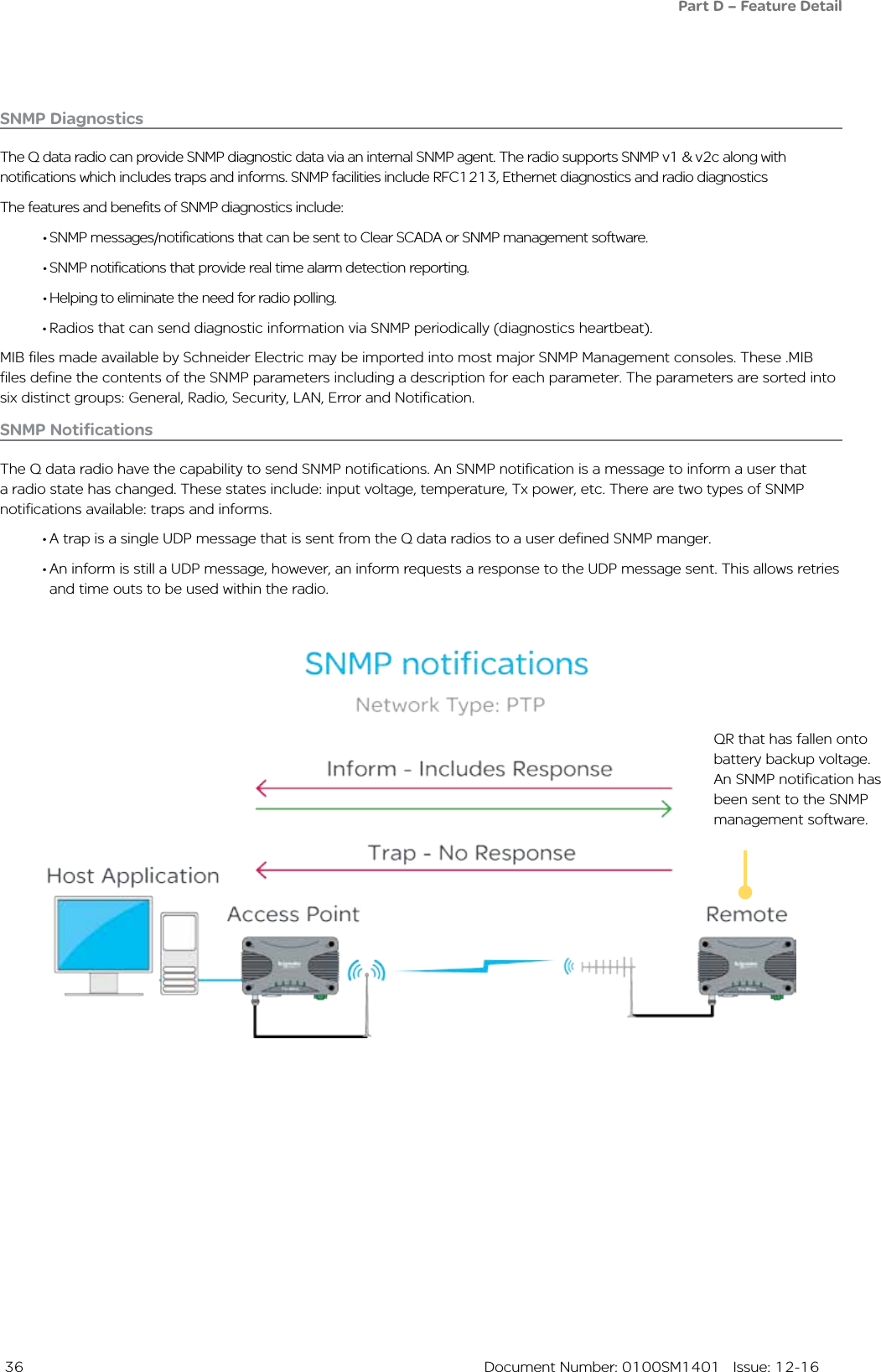
![34 Document Number: 0100SM1401 Issue: 12-16Network Address Translation (NAT)Network Address Translation (NAT) provides a radio in IP routing mode, the ability to perform local port forwarding. Port forwarding can be beneficial in a network where: - An IP network has run out of available IP addresses. - Multiple devices co-exist on a single IP network while sharing the same IP address.In a standard IP routing radio network, each radio behaves as a network gateway to each of the local subnets. This type of network consists of: - A number of LANs: These are the subnetworks residing on the local side of each radio gateway. To subnet these networks, each LAN requires a uniquely allocated IP range.- A single Radio WAN: Each radio gateway is configured with a unique WAN address. This creates a subnetwork for the radio channel.NAT port forwarding can eliminate the requirement for unique addressing within the LAN subnets by translating the source address of message sent from a device residing on the LAN with the address allocated to the radio router’s WAN network.Devices residing on a local subnet will no longer be addressed by their unique IP address, rather, the IP address of the radio gateway along with a unique port number.When port forwarding is being configured, each IP device within a local network is allocated one port number on the radio gateway and a port forwarding rule is entered into the gateway to define:Gateway Listening Port - The port number which has been allocated to a single device on the radio gateways LAN. When a message addresses this port number and forwarded to the radio gateway, the corresponding port forwarding rule will be executed.IP address and port number of the allocated device - When the Gateway Listening Port is addressed, the corresponding rule is executed, where the message address will be translated to the IP address and port number defined in these rule parameters.Virtual LAN (VLAN)VLAN can help provide isolation between separate entities who share a single network. For example, Department A may require access to radio configuration/Diagnostics, while Department B may only requires access to SCADA information. By implementing VLAN, a virtual network segregation can be implemented to help isolate each of the departments from one another.The following diagram shows managed switches placing separate hosts onto unique VLANs. Each remote has been configured to use VLAN 1 on the ETH1 interface, which provides access to radio services, and VLAN 2 for the ETH2 interface for SCADA control access. Part D – Feature Detail[VLAN 1] Network Management[VLAN 2] SCADA ControlUn-Tagged packetsETH1Network ManagementSCADA ControlETH2ETH2Ethernet SwitchWANEthernet SwitchETH1 Optional connection for radio system diagnostics](https://usermanual.wiki/Schneider-Electric-Systems-Canada/QR150/User-Guide-3273680-Page-34.png)
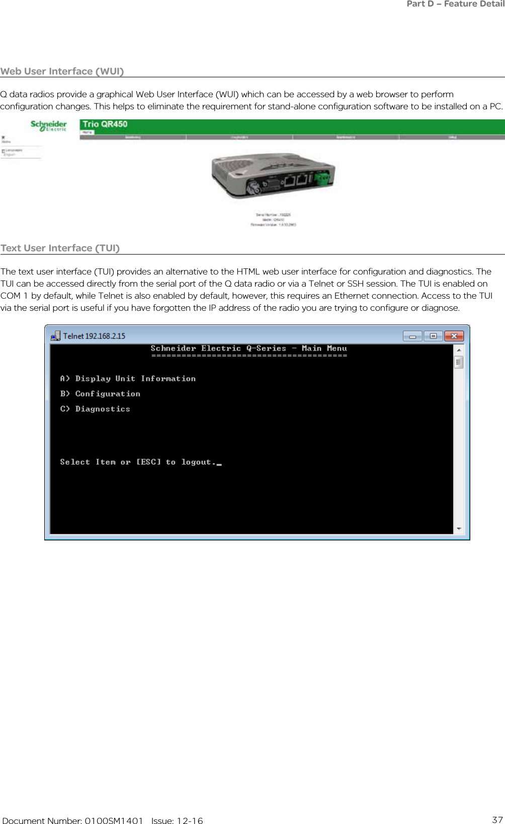
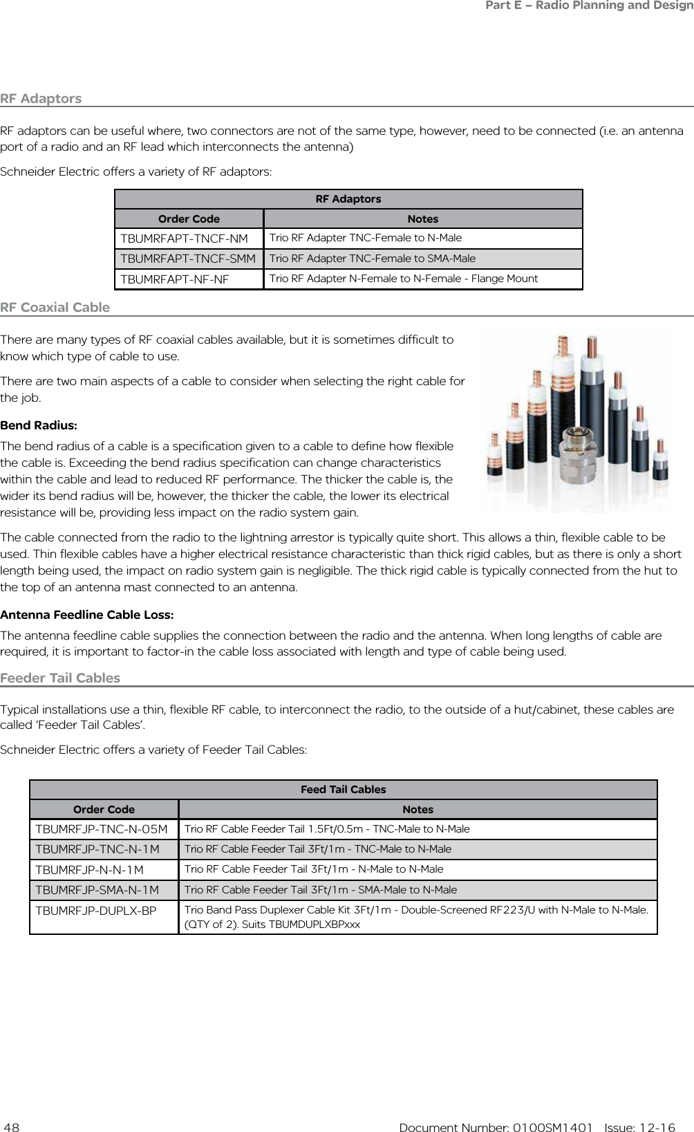
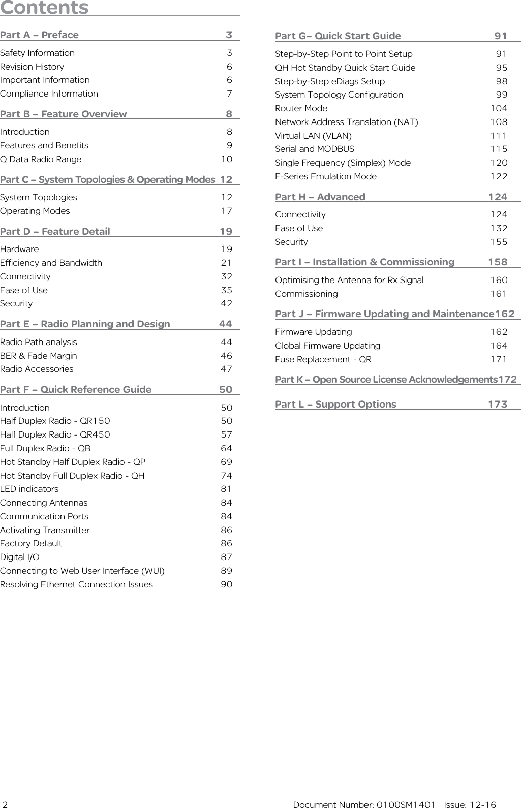
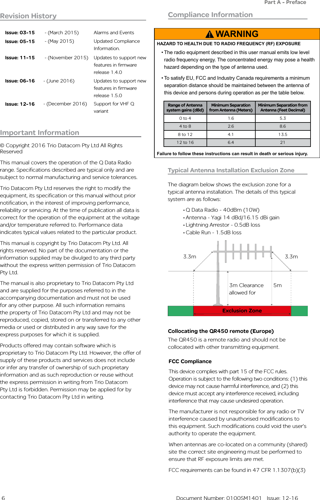
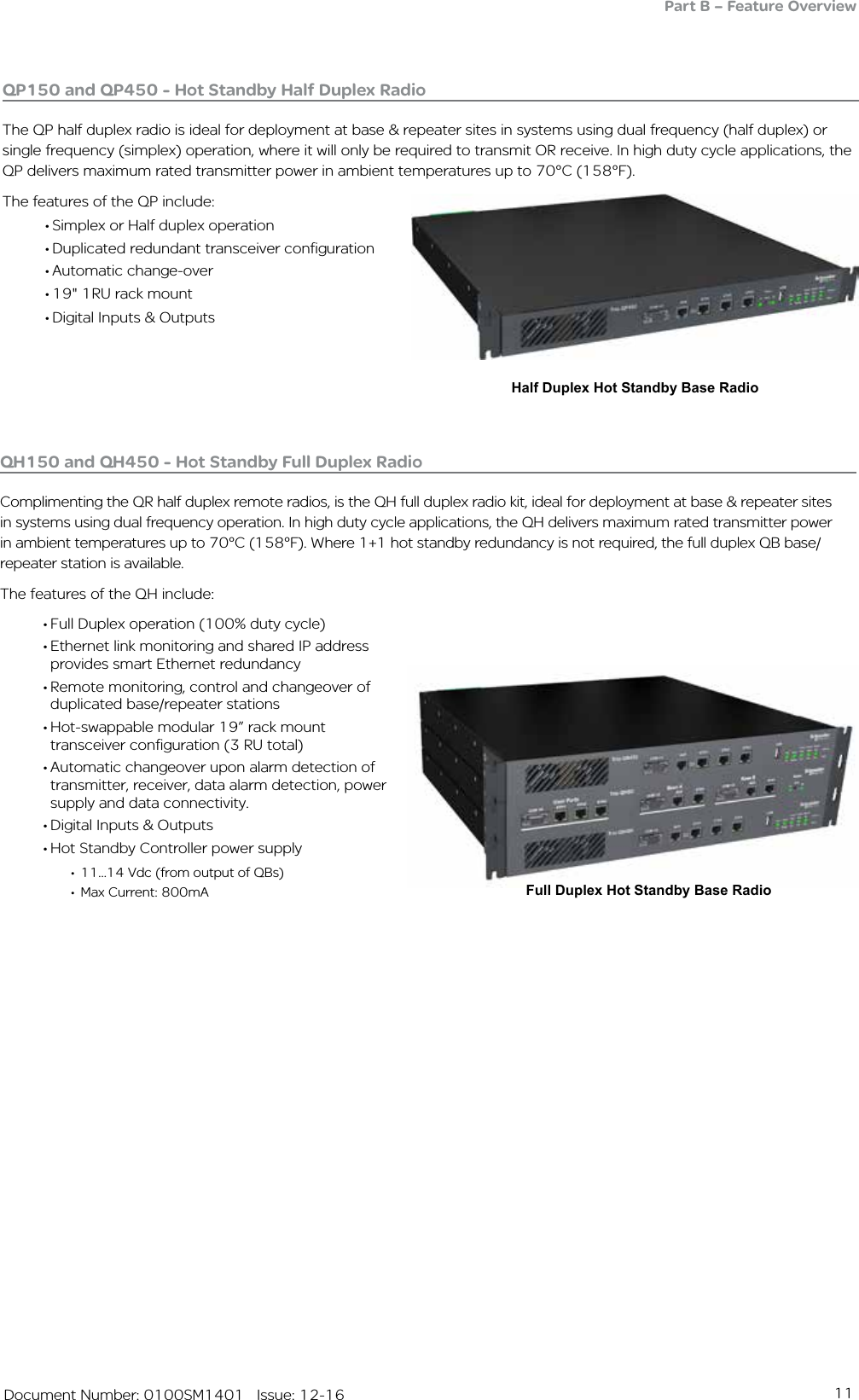
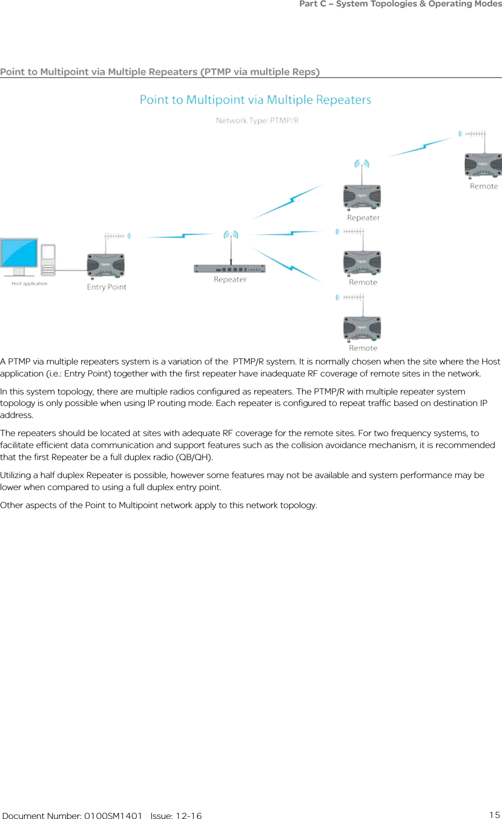
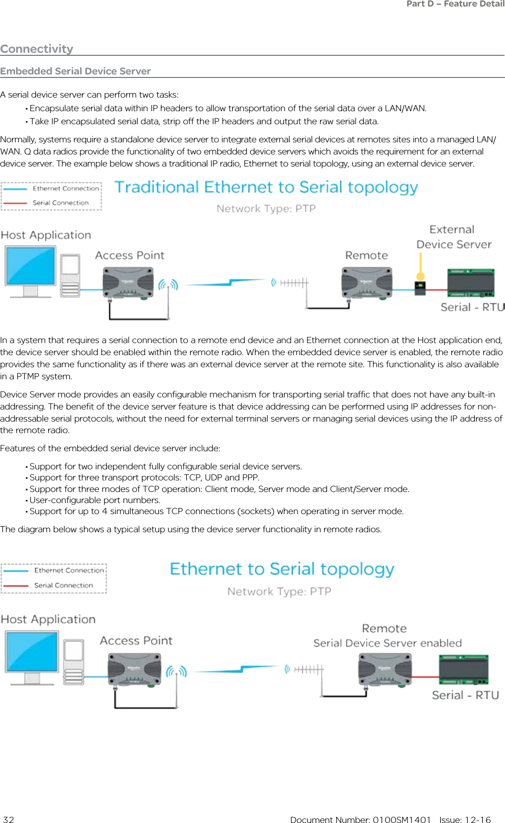
![49 Document Number: 0100SM1401 Issue: 12-16Lightning ArrestorsA lightning arrestor is used to help minimise lightning damage to radio devices. Lightning arrestors are made to bleed off electrostatic build-up to help prevent a direct lightning strike from hitting the antenna system. Also, if a lightning strike happens nearby, the arrestor helps to route the energy to ground.The lightning arrestor is typically installed on the inside of a radio hut, between a coaxial tail lead the antenna feeder cable. The lightning arrestor comes with an N-Type female socket on each end. Schneider Electric offers a variety of Lightning Arrestors:Antennas Feedline Cable Loss characteristicsCable Diameter [order code reference]150 MHz 450 MHz 900 MHz 2500 MHzdB/100 ft dB/100 m dB/100 ft dB/100 m dB/100 ft dB/100 m dB/100 ft dB/100 m10 mm (0.4 in.) [TBUMRFANT-xxxxxx-A]1.5 5.0 2.7 8.9 3.9 12.8 6.8 22.213 mm (0.5 in.) Heliax [TBUMRFANT-xxxxxx-B]0.8 2.7 1.5 4.8 2.1 6.9 3.6 12.0Antenna Feedline CablesOrder Code NotesTBUMRFANT-99F30M-B Trio RF Cable Antenna Feedline 99Ft/30m, 0.5in/13mm Heliax N-Male To N-Male (LDF4-50A or equivalent)TBUMRFANT-75F22M-B Trio RF Cable Antenna Feedline 75Ft/22m, 0.5in/13mm Heliax N-Male To N-Male (LDF4-50A or equivalent)TBUMRFANT-75F22M-A Trio RF Cable Antenna Feedline 75Ft/22m, 0.4in/10mm N-Male To N-Male (LMR-400 or equivalent)TBUMRFANT-50F15M-A Trio RF Cable Antenna Feedline 50Ft/15m, 0.4in/10mm N-Male To N-Male (LMR-400 or equivalent)TBUMRFANT-25F7M-A Trio RF Cable Antenna Feedline 25Ft/7m, 0.4in/10mm N-Male To N-Male (LMR-400 or equivalent)TBUMRFANT-10F3M-A Trio RF Cable Antenna Feedline 10Ft/3m, 0.4in/10mm N-Male To N-Male (LMR-400 or equivalent)Feeder Tail CablesAs the antenna needs to be mounted up high, a longer length of RF cable needs to run from the outside of the hut/cabinet, to the antenna, this cable is called ‘Antenna Feedline Cable’.Schneider Electric offers a variety of Antenna Feedline Cables:As typical installations using antenna feedline cables use long lengths, it is important to consider the loss characteristics of the cable being used, see the loss characteristics table below:Lightning ArrestorsOrder Code Frequency range Protected Side ConnectorSurge Side Connector Mounting Style VSWR NotesTBUMLT-ARRES-TYPEA 125 MHz to 1 GHz N-Female N-Female Bulkhead with right angle bracket1.1:1 Turn-on: 600 Vdc ±20%TBUMLT-ARRES-TYPEB 2 to 6 GHz N-Female N-Female Bulkhead inline (no bracket)1.3:1 Surge: 10kA IEC 61000-4-5 8/20μs waveform](https://usermanual.wiki/Schneider-Electric-Systems-Canada/QR150/User-Guide-3273680-Page-49.png)
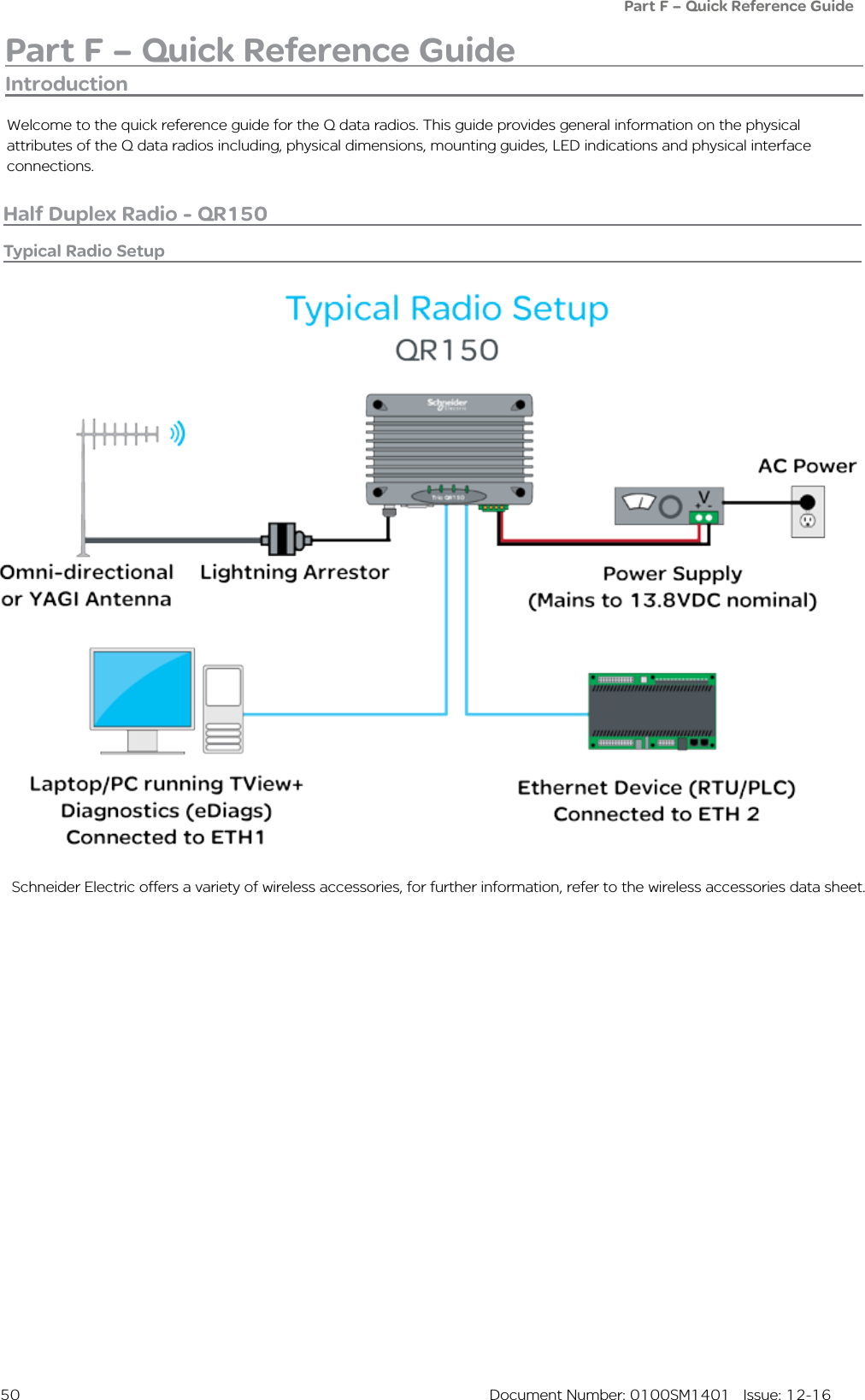
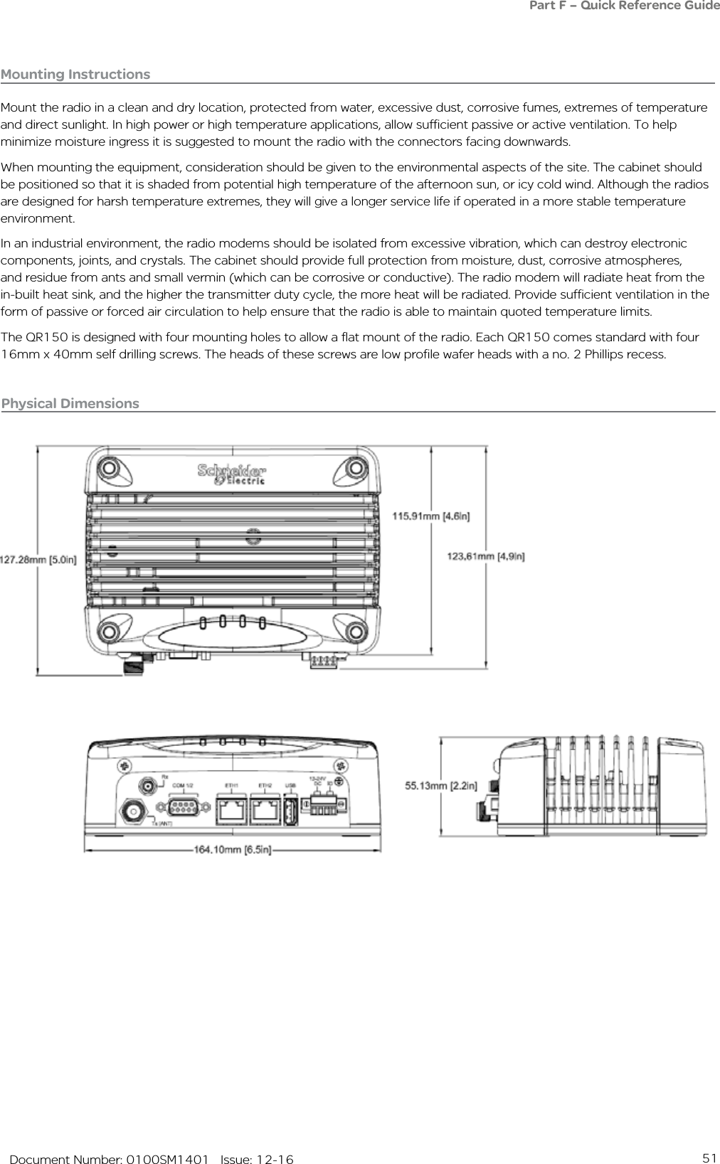
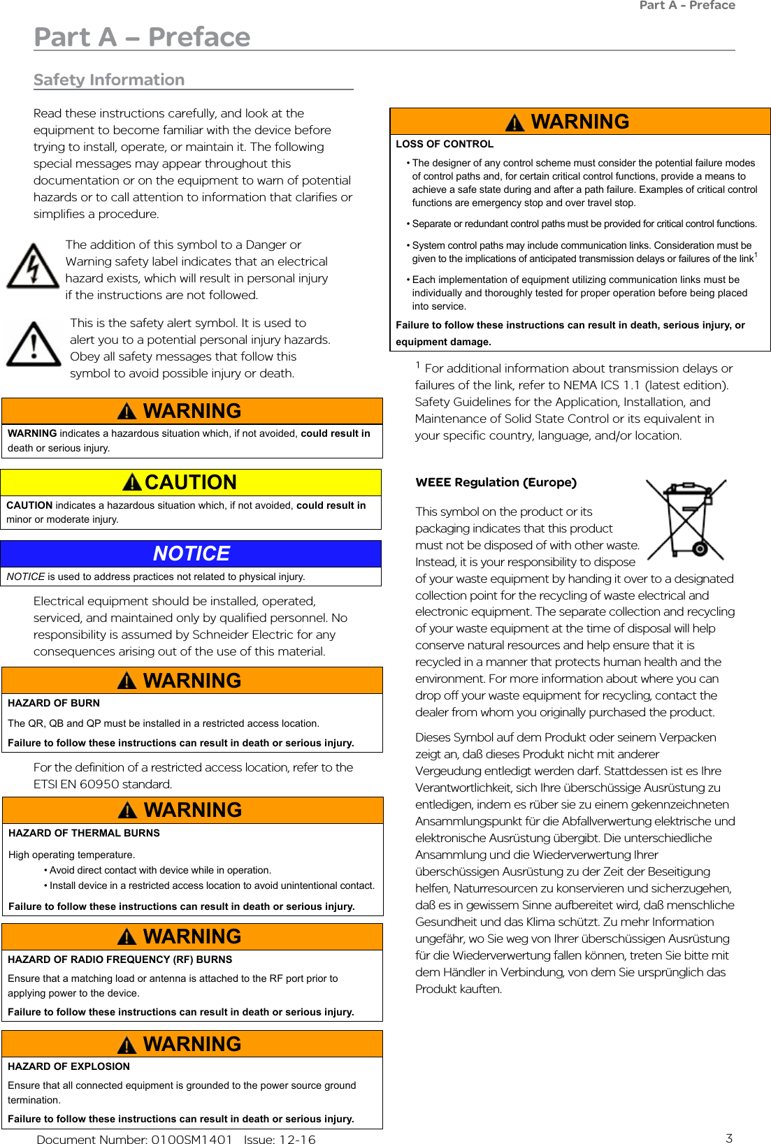
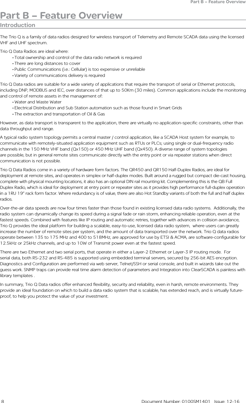
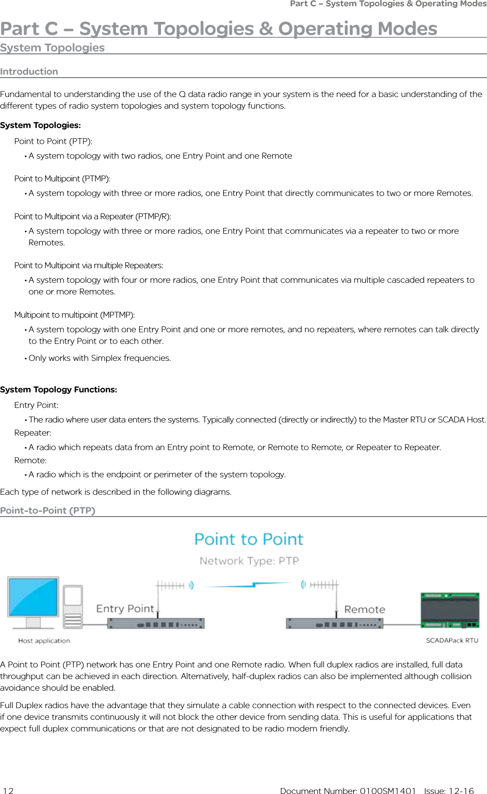
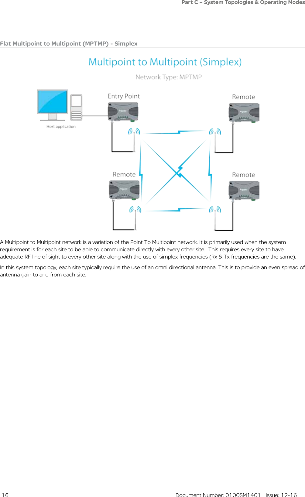
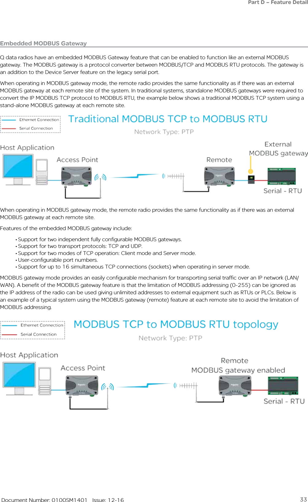
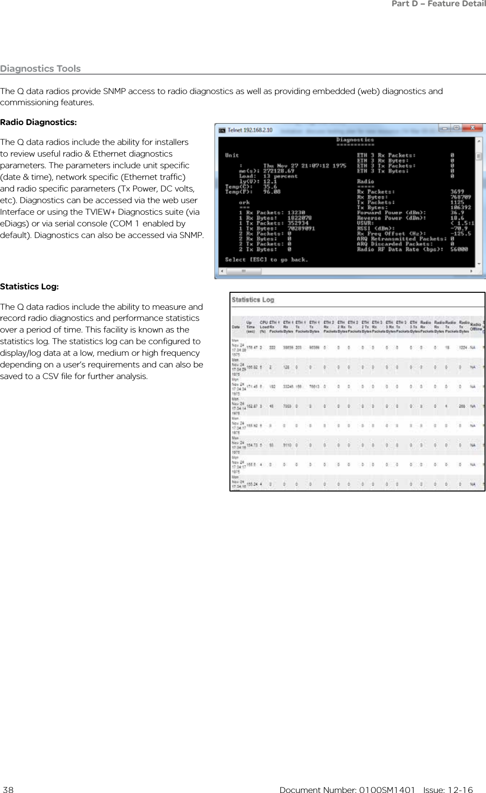
![52 Document Number: 0100SM1401 Issue: 12-16Part F – Quick Reference Guide DIN rail mounting kitAn optional DIN rail mounting kit is available for the QR150. The mount is screwed onto the bottom of the QR150 giving the unit the ability to be simply ‘clipped’ and locked onto a 7.5 mm by 35 mm (0.3 in. by 1.4 in.) DIN rail.Each DIN rail kit supplies:• x1 DIN rail mounting bracket• x1 DIN rail clip• x4 Countersunk M4X8 screws (to mount DIN rail clip to bracket)• x4 M4 nuts (to mount DIN rail clip to bracket)• x4 Pan head M3X6 screws (to mount spread-spectrum radio to bracket)• x4 Pan head M4X2.5 screws (to mount M-Series to bracket)• x4 Pan head M4X8 screws (to mount QR150/QR450 to bracket)Drawings not to scale.118.5mm [4.66in.] (128.5mm [5.05in.] With DIN clip fitted on rear)12mm [0.47in.]2.5mm [0.09in.]60mm [2.36in.]175mm [6.89in.]DIN rail mounting bracket(70mm [2.75in.] With DIN clip fitted on bottom)2.5mm [0.09in.]11.5mm [0.45in.]](https://usermanual.wiki/Schneider-Electric-Systems-Canada/QR150/User-Guide-3273680-Page-52.png)
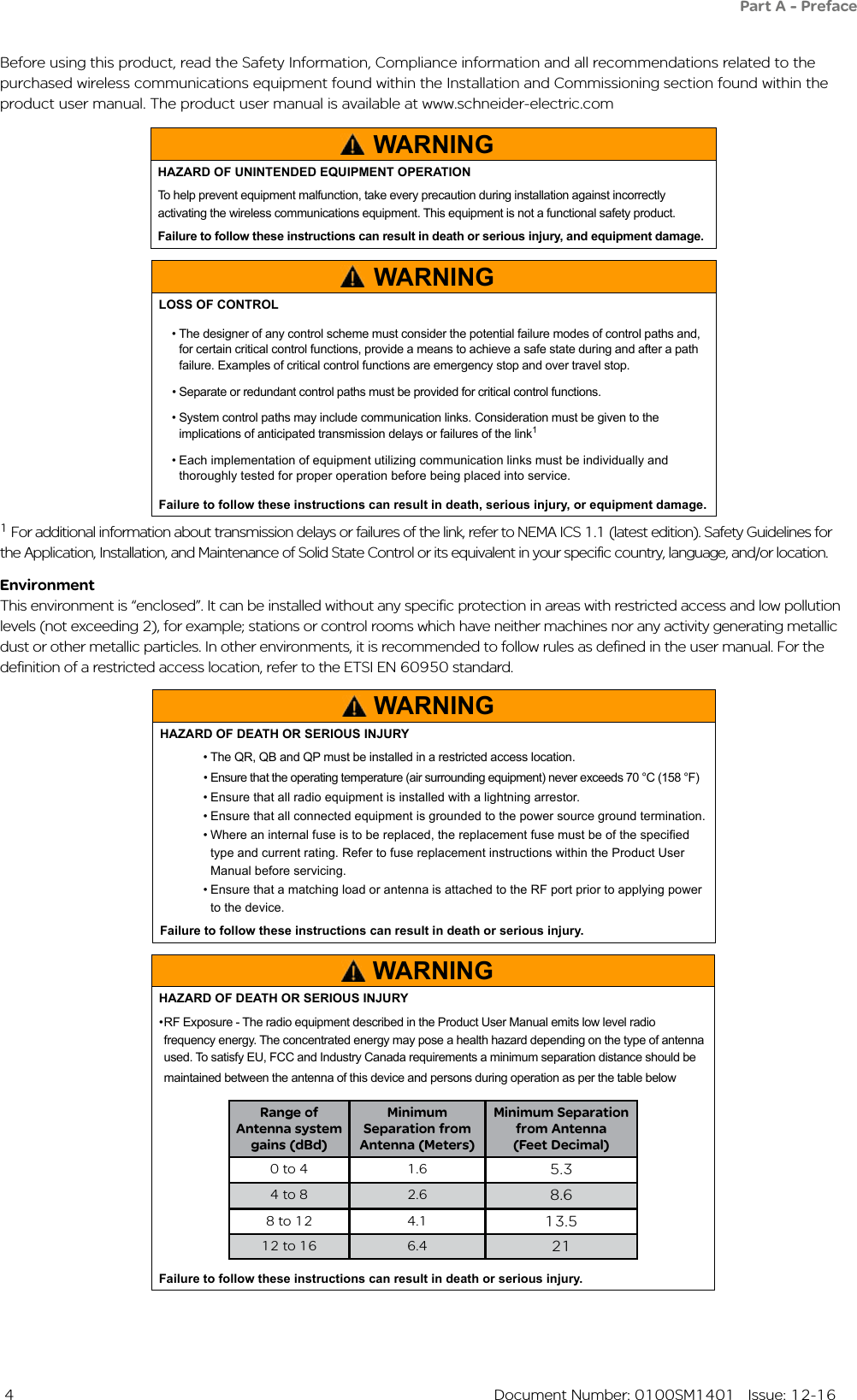
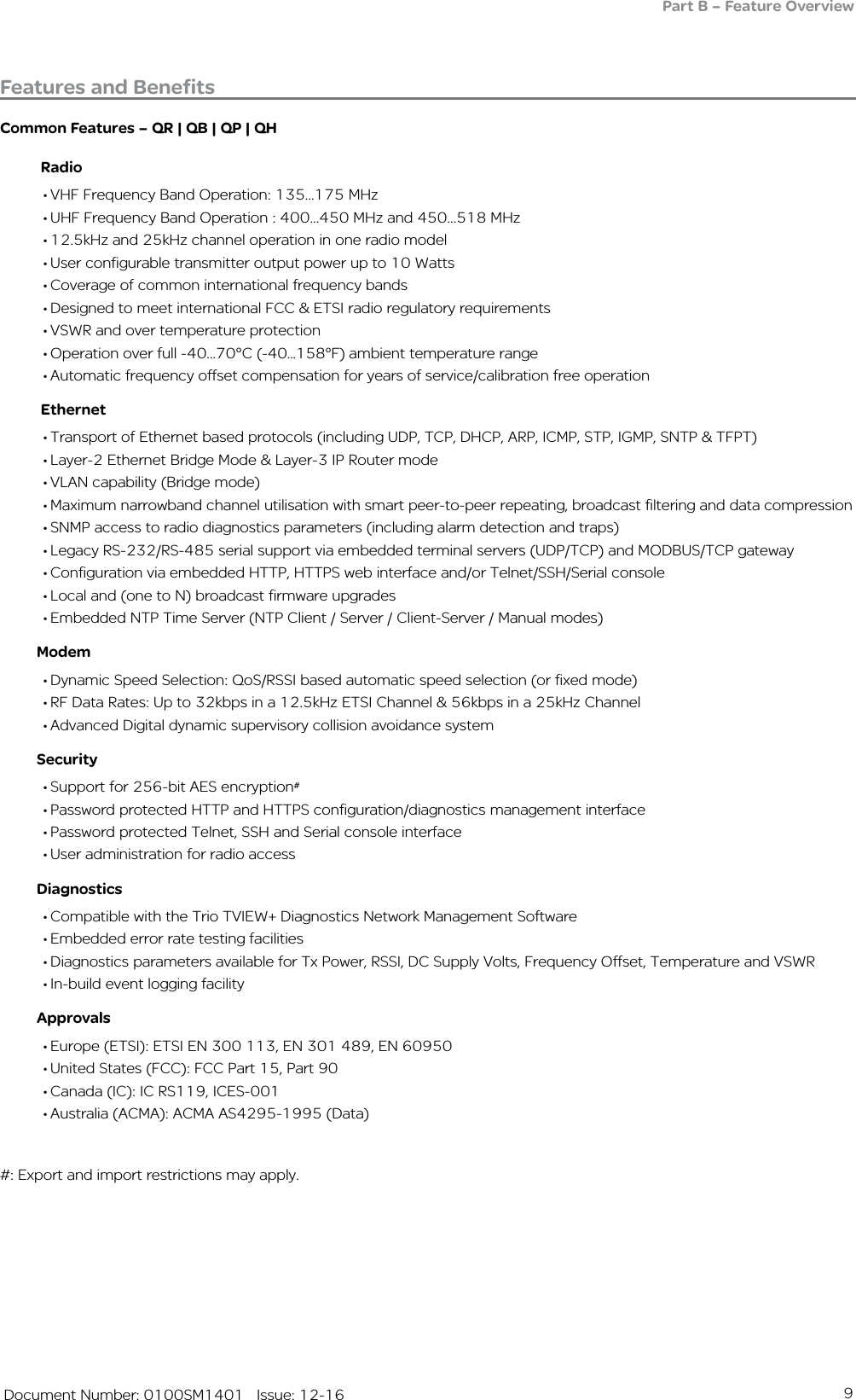
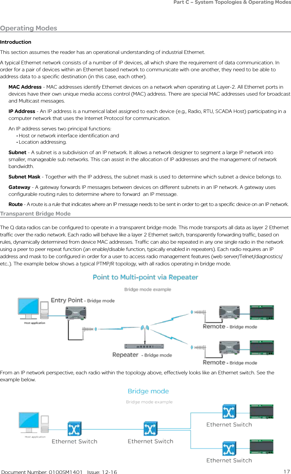
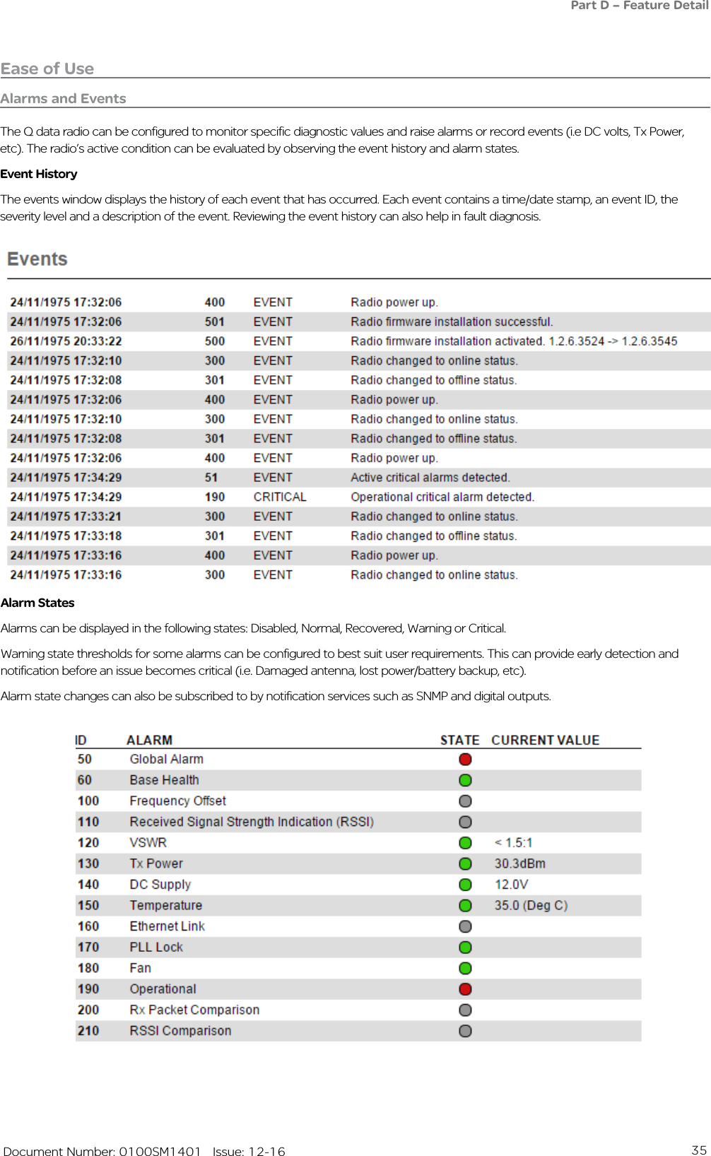
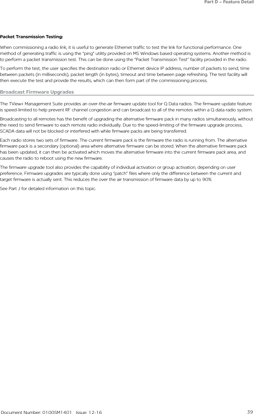
![53 Document Number: 0100SM1401 Issue: 12-16Part F – Quick Reference Guide26mm [1.02in.]34mm [1.33in.]34mm [1.34in.]58.5mm [2.3in.]70.5mm [2.77in.]10mm [0.39in.]58mm [2.28in.] 58mm [2.28in.]59mm [2.32in.]10mm [0.39in.]5mm [0.19in.]7mm [0.27in.]70.5mm [2.77in.]34mm [1.33in.]](https://usermanual.wiki/Schneider-Electric-Systems-Canada/QR150/User-Guide-3273680-Page-53.png)
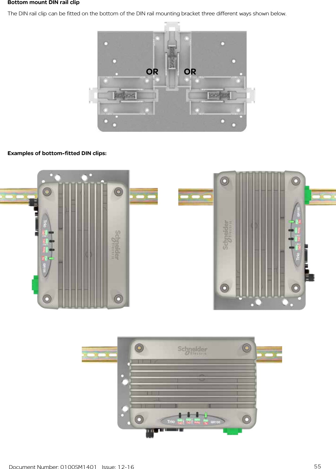
![54 Document Number: 0100SM1401 Issue: 12-16DIN rail clipThe DIN rail clip has a spring loaded latch to allow easy installation/removal of the radio device being installed.The DIN rail clip can be fitted to the DIN rail mounting bracket x5 different ways to allow as much installation flexibility as possible.Rear mount DIN rail clipThe DIN rail clip can be fitted on the rear of the DIN rail mounting bracket two ways shown below.Examples of rear-fitted DIN clips:ORPart F – Quick Reference Guide 65mm [2.55in.]5mm [0.19in.]44mm [1.73in.]82mm [3.22in.]9mm[0.35in.]9mm[0.35in.]5mm [0.19in.]19mm [0.74in.]4mm [0.15in.]](https://usermanual.wiki/Schneider-Electric-Systems-Canada/QR150/User-Guide-3273680-Page-54.png)
![59 Document Number: 0100SM1401 Issue: 12-16DIN rail mounting kitAn optional DIN rail mounting kit is available for the QR450. The mount is screwed onto the bottom of the QR450 giving the unit the ability to be simply ‘clipped’ and locked onto a 7.5 mm by 35 mm (0.3 in. by 1.4 in.) DIN rail.Each DIN rail kit supplies:• A DIN rail mounting bracket• A DIN rail clip• x4 Countersunk M4X8 screws (to mount DIN rail clip to bracket)• x4 M4 nuts (to mount DIN rail clip to bracket)• x4 Pan head M3X6 screws (to mount Spread spectrum radio to bracket)• x4 Pan head M4X2.5 screws (to mount M-Series to bracket)• x4 Pan head M4X8 screws (to mount QR150/QR450 to bracket)Drawings not to scale.118.5mm [4.66in.] (128.5mm [5.05in.] With DIN clip fitted on rear)12mm [0.47in.]2.5mm [0.09in.]48.5mm [1.9in.]175mm [6.89in.]DIN rail mounting bracket(58.5mm [2.3in.] With DIN clip fitted on bottom)Part F – Quick Reference Guide 2.5mm [0.09in.]12-24](https://usermanual.wiki/Schneider-Electric-Systems-Canada/QR150/User-Guide-3273680-Page-59.png)
![60 Document Number: 0100SM1401 Issue: 12-1626mm [1.02in.]34mm [1.33in.]34mm [1.34in.]58.5mm [2.3in.]70.5mm [2.77in.]10mm [0.39in.]58mm [2.28in.] 58mm [2.28in.]59mm [2.32in.]10mm [0.39in.]5mm [0.19in.]7mm [0.27in.]70.5mm [2.77in.]Part F – Quick Reference Guide34mm [1.33in.]](https://usermanual.wiki/Schneider-Electric-Systems-Canada/QR150/User-Guide-3273680-Page-60.png)
![61 Document Number: 0100SM1401 Issue: 12-16DIN rail clipThe DIN rail clip has a spring loaded latch to allow easy installation/removal of the radio device being installed.The DIN rail clip can be fitted to the DIN rail mounting bracket x5 different ways to allow as much installation flexibility as possible.Rear mount DIN rail clipThe DIN rail clip can be fitted on the rear of the DIN rail mounting bracket two ways shown below.Examples of rear fitted DIN clips:ORPart F – Quick Reference Guide 65mm [2.55in.]5mm [0.19in.]44mm [1.73in.]82mm [3.22in.]9mm[0.35in.]9mm[0.35in.]5mm [0.19in.]19mm [0.74in.]4mm [0.15in.]](https://usermanual.wiki/Schneider-Electric-Systems-Canada/QR150/User-Guide-3273680-Page-61.png)
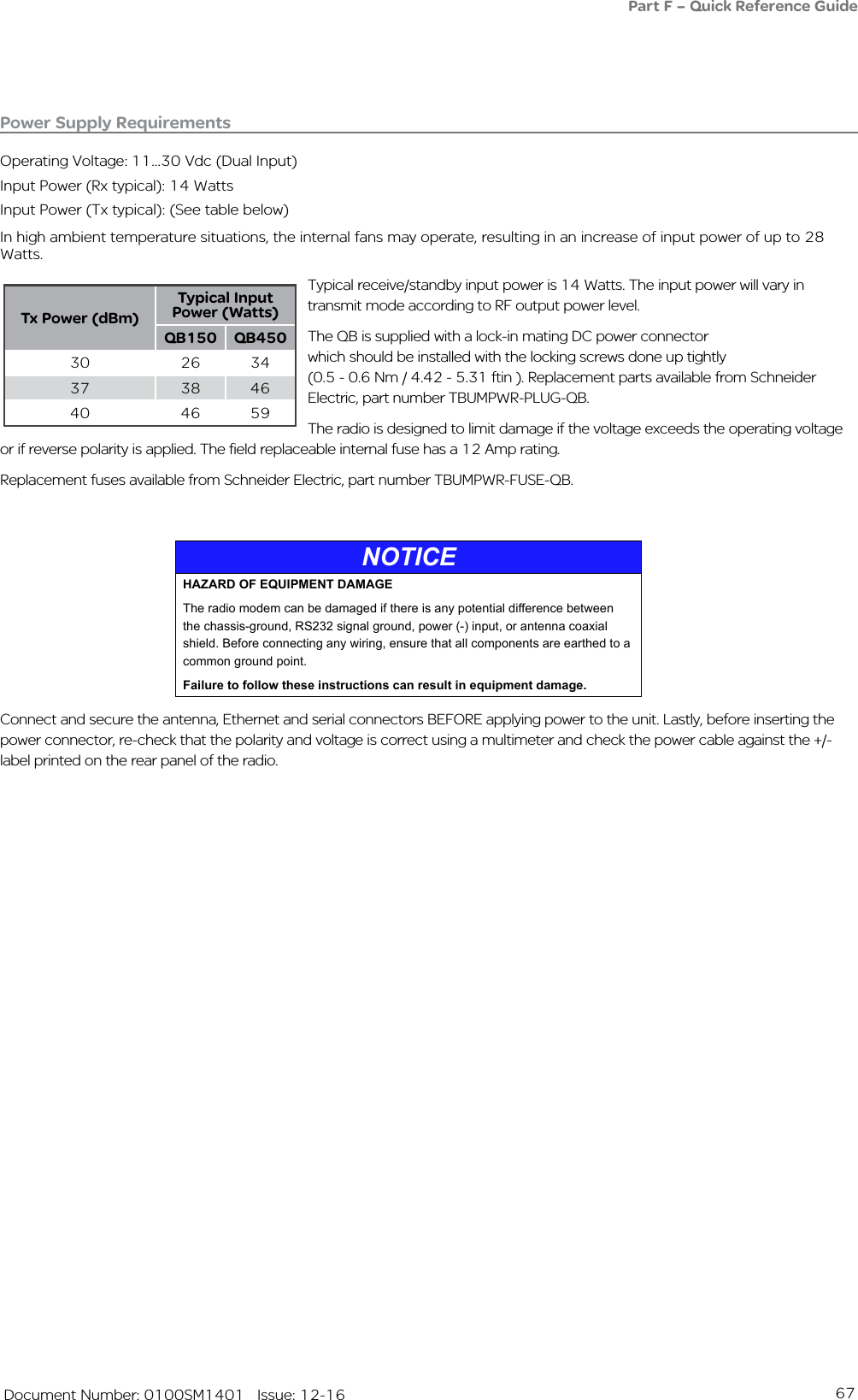
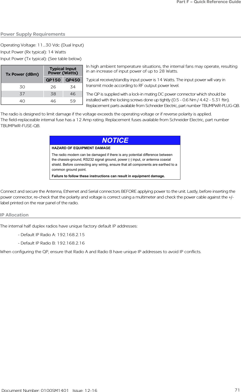
![76 Document Number: 0100SM1401 Issue: 12-16Physical DimensionsHot Standby is configured using 2 x QB full duplex radios + 1 x Hot Standby Controller (19 in. 1 RU each) for a total of 19 in. (483 mm) 3 RU rack mount.Without mounting brackets, D:424 x H:133.3 x W:436.5 mm (D:16.7 x H:5.25 x W:17.18 in.)Part F – Quick Reference GuidePower Supply RequirementsOperating Voltage: 11...30 Vdc (Dual Input)Input Power (Rx typical): 35 Watts Input Power (Tx typical): (See table below)In high ambient temperature situations, the internal fans may operate, resulting in an increase of input power of up to 56 Watts [x2 QBs].Typical receive/standby input power is 35 Watts. The input power will vary in transmit mode according to RF output power level.Each QB within the hot standby arrangement is supplied with a lock-in mating DC power connector which should be installed with the locking screws done up tightly (0.5 - 0.6 Nm / 4.42 - 5.31 ftin ). Replacement parts available from Schneider Electric, part number TBUMPWR-PLUG-QB.The radios are designed to limit damage if the voltage exceeds the operating voltage or if reverse polarity is applied. Each QB has a field-replaceable internal fuse with a 12 Amp rating. Replacement fuses available from Schneider Electric, part number TBUMPWR-FUSE-QB.Tx Power (dBm)Typical Input Power (Watts)QH150 QH45030 48 5537 59 6740 68 80](https://usermanual.wiki/Schneider-Electric-Systems-Canada/QR150/User-Guide-3273680-Page-76.png)
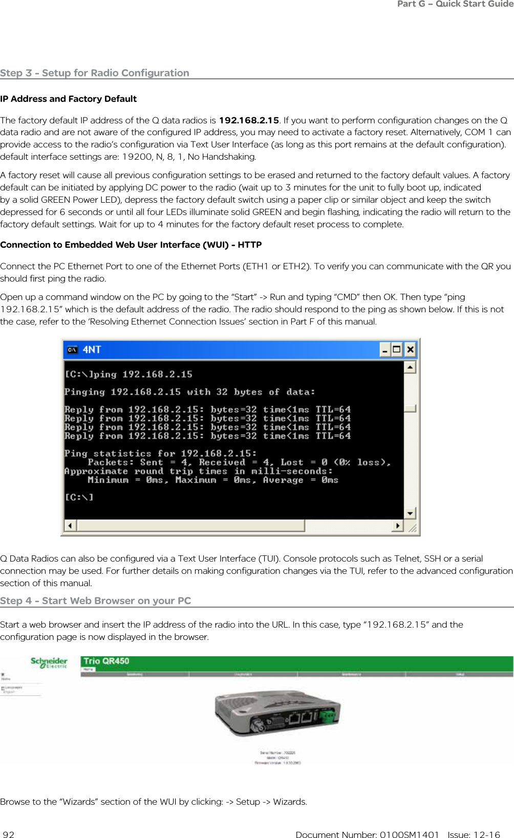
![95 Document Number: 0100SM1401 Issue: 12-16QH Hot Standby Quick Start GuideIntroductionThis document describes the seven key steps required for connecting and configuring a single QH arrangement.Step 1 - RF and DC power connectionConnect the DC power and Antenna ports following the connection diagrams shown in the QH Quick Reference Guide section.If antennas are not available, terminate the radios antenna ports with a suitable load or attenuator.Do not apply DC power to the hot standby arrangement at this stage.Step 3 - Apply DC PowerEnsure that the radio select switch on the hot standby controller is switched to Radio A.Apply DC power to the hot standby arrangement, allowing up to two minutes for the radios to power up.Once the hot standby arrangement is powered up (indicated by a solid green LED state on the pwr LEDs), ensure that the HSC radio select LED for Radio A is illuminated amber. This indicates that Radio A is forced online.Step 4 - Start Web Browser on your PCEnsure that each QB radio is in factory default state. This is done by depressing the hidden factory default button on the front panel of each QB for 5 seconds. Allow up to three minutes for the factory default process to complete.Connect your PC Ethernet port to the ETH 2 interface of Base A. Verify that your PC can communicate with Base A by performing a ping test. The default IP address of a Q data radio is 192.168.2.15.Start a web browser and insert the IP address of the radio into the URL. In this case, type “192.168.2.15” and the configuration page should now be displayed in the browser.Further details on factory default and WEB browser connection can be found in the QB Quick Start Guide.Step 2 - Interface ConnectionsConnect the interface cables following the diagram below (leaving the QB interconnecting cable [ETH3-ETH3] disconnected).Part G – Quick Start GuideLeave ETH3-ETH3 disconnected](https://usermanual.wiki/Schneider-Electric-Systems-Canada/QR150/User-Guide-3273680-Page-95.png)
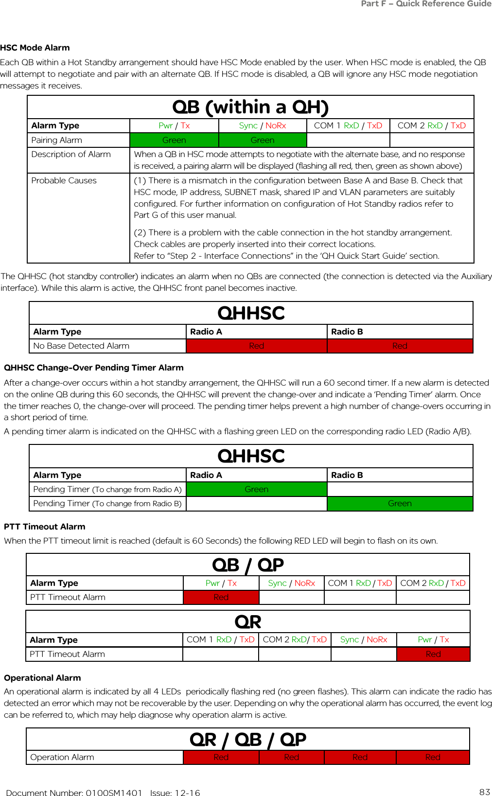
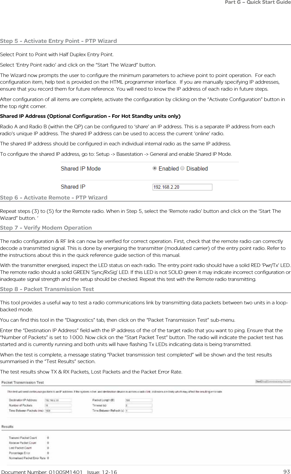
![96 Document Number: 0100SM1401 Issue: 12-16Step 5 - Radio ConfigurationThere are three main QB configuration parameters to review for hot standby operation:• HSC Mode: Configure the QB to operate within a hot standby arrangement by enabling HSC mode. To access HSC mode, go to: Setup -> Basestation -> General and enable the HSC Mode. Once HSC Mode is enabled, a range of hot standby configuration parameters becomes available.• Unique IP Address: Each QB radio within a hot standby arrangement requires its own unique IP address. To configure the IP address, go to: Setup -> Network -> Ethernet -> IP Address . For this example, the following unique IP address allocations have been given:- Base A IP: 192.168.2.21- Base B IP: 192.168.2.22• Shared IP Address: The two QB radios within a hot standby arrangement can be configure to ‘share’ an IP address. This is an IP address separate from the radio’s unique IP address. The ‘online’ base within the hot standby arrangement assumes ownership of the shared IP address. The shared IP address has to be configured in Base A & B. To configure the shared IP address, enable HSC mode, then go to: Setup -> Basestation -> General and enable Shared IP Mode. For this example, the following shared IP address has been allocated: - Base A & B Shared IP: 192.168.2.20When these parameters have been configured, activate the configuration. Once the configuration is activated Base A will attempt to negotiate and pair with an alternate QB. As Base B is still in a factory default state, HSC mode negotiation messages will be ignored (until HSC mode is enabled). This will cause Base A to indicate a pairing alarm, which can be ignored until Base B has been configured.QB (within a QH)Alarm Type Pwr / Tx Sync / NoRx COM 1 RxD / TxD COM 2 RxD / TxDPairing Alarm Green GreenWhen Base A has been successfully configured, perform the following steps: - Force Base B online using the radio select switch on the QHHSC - Begin from Step 4 and configure Base BPart G – Quick Start Guide[For further details on alarms, refer to Part F - Quick Reference Guide]](https://usermanual.wiki/Schneider-Electric-Systems-Canada/QR150/User-Guide-3273680-Page-96.png)
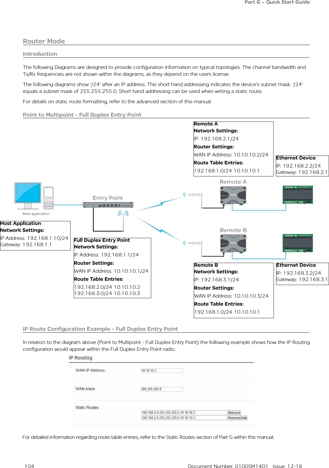
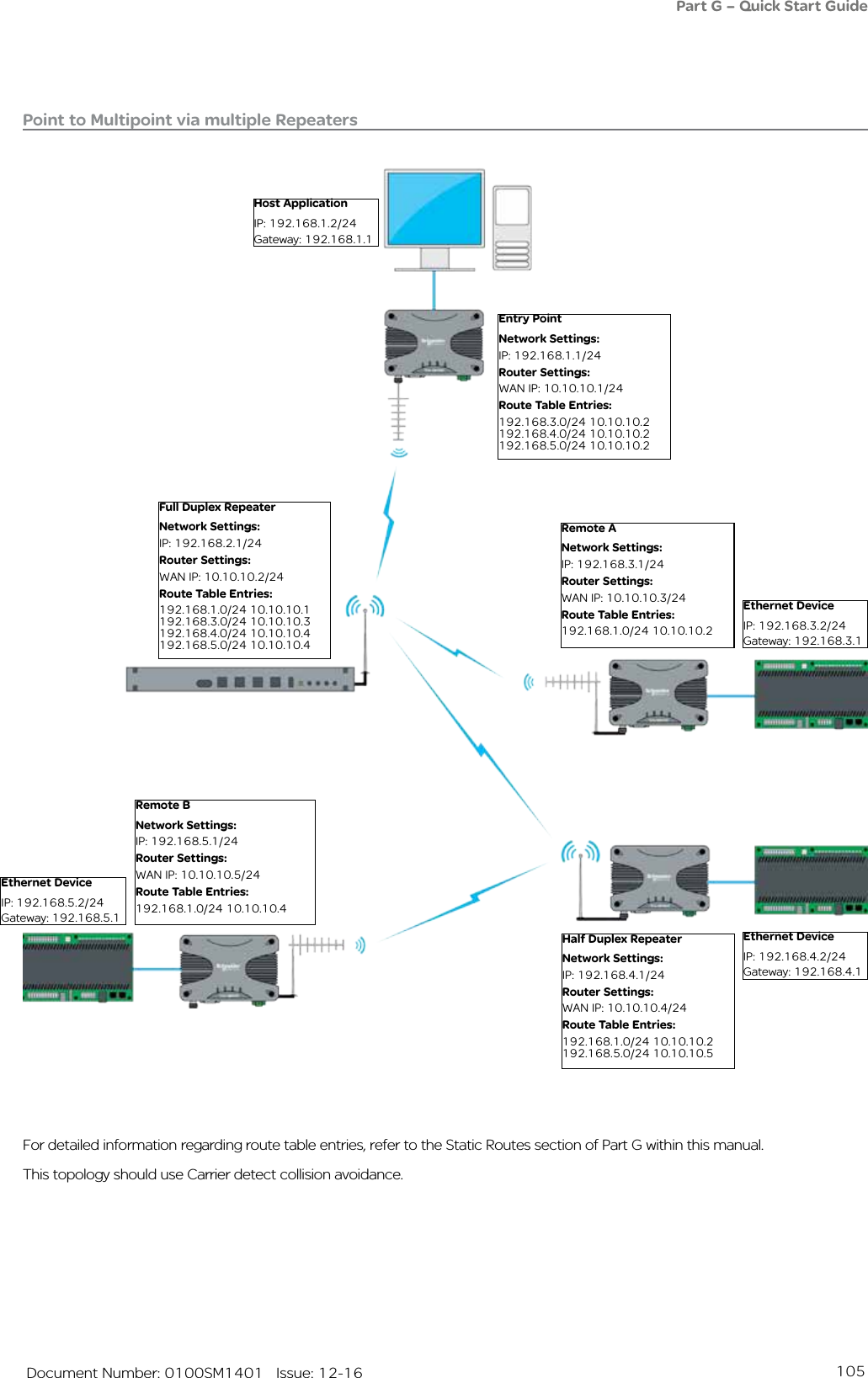
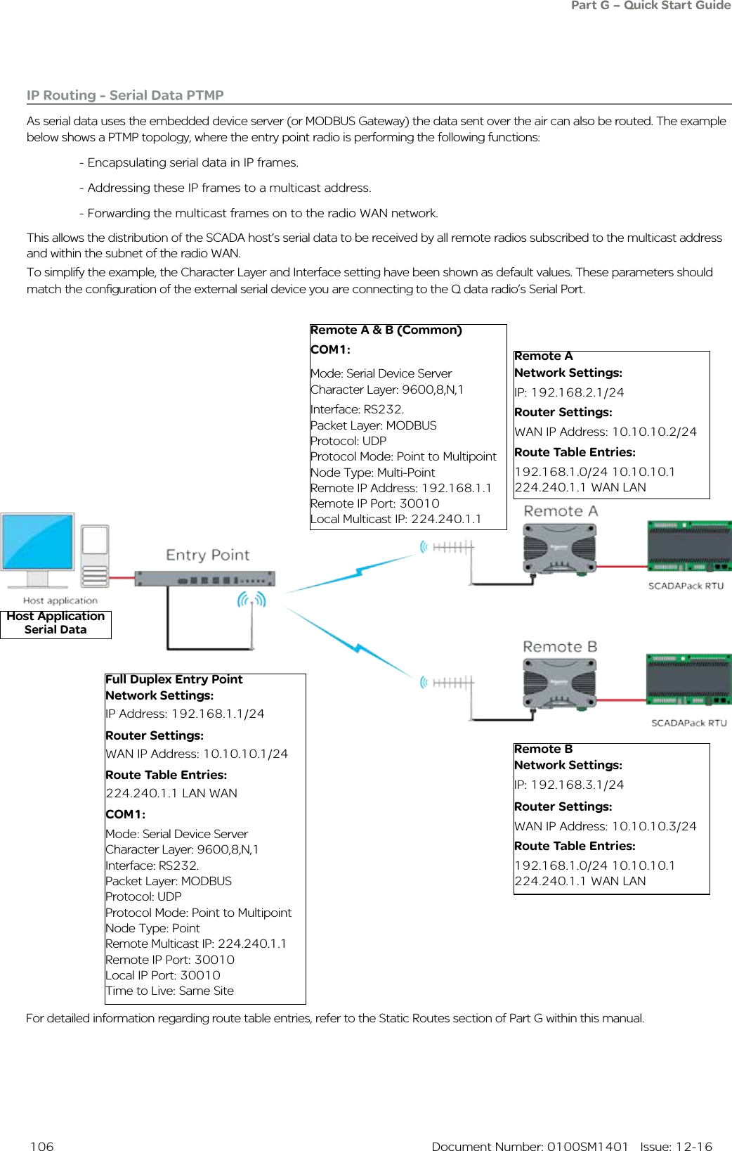
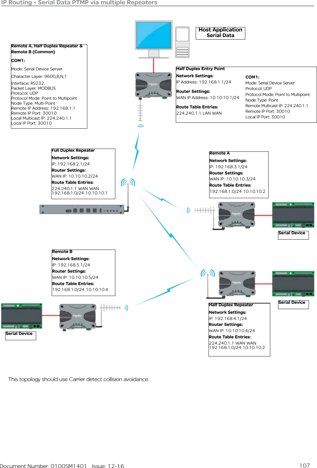
![103 Document Number: 0100SM1401 Issue: 12-16Static RoutesWhile operating in IP routing mode, a radio to must be configured with a manually populated static route table.That static route table can be accessed via Setup -> IP Routing (only available while radio operating mode is set to IP Routing). To add a new route to the table, select the ‘Add’ button. This will add a new, empty table entry, which will need to be manually populated with a static route. The added routes must be populated in an acceptable format. Route formatting information is shown below.Formatting a static routeThere are multiple formatting methods in which static route rules can be written.Routing rules may define a forwarding path to a gateway or to an interface (LAN or WAN) which is shown in the examples below as <Gateway IP or ”LAN” or ”WAN”>. Examples:Using a network address and a subnet mask to define a range of target IP addresses to be forwarded to a gateway Route Format: <Network Address> <Netmask> <Gateway IP or ”LAN” or ”WAN”> Example: 192.168.1.0 255.255.255.0 10.10.10.1 Using the CIDR format, a range of IP address may be routed to a specified gateway. The range may include the multicast address space. The network address must be valid (base address of the range) defined by the CIDR prefix. Route Format: <Network Address/CIDR> <Gateway IP or ”LAN” or ”WAN”> Example: 192.168.1.0/24 10.10.10.1A single host or multicast address can be defined and routed to a gateway or an interface as described above. Route Format: <IP Address> <Gateway IP or ”LAN” or ”WAN”> Example: 192.168.1.20 10.10.10.1For each multicast address required to traverse from one interface to another or to effect a store and forward, a route instruction is required. (Where square brackets represent optional route entry parameters. Route Format: <Multicast IP Address> [FROM IP Address] “WAN” or ”LAN” “WAN” or ”LAN” [“WAN” or ”LAN”] Example: 224.240.1.1 192.168.1.40 WAN WAN LANThere may only be one occurrence of LAN in the rule above. A second occurrence of WAN will effect a store and forward action.All routes can also have comments added to them. Comments can be added to the end of each route by prefixing the comment text with an exclamation mark ‘!’. Example: 192.168.1.0/24 10.10.10.1 !Mountain Top RoutePart G – Quick Start Guide](https://usermanual.wiki/Schneider-Electric-Systems-Canada/QR150/User-Guide-3273680-Page-103.png)
![108 Document Number: 0100SM1401 Issue: 12-16Network Address Translation (NAT) NAT ConfigurationNAT is only available when the radio is operating in IP Routing mode.NAT configuration parameters can be accessed within the radio’s configuration page by browsing to: Setup -> IP Routing.IntroductionAs of firmware version 1.4.0, Network Address Translation (NAT) is available.The following Diagrams are designed to provide configuration information on typical topologies. The channel bandwidth and Tx/Rx frequencies are not shown within the diagrams, as they depend on the user’s license.The following diagrams show ‘/24’ after an IP address. This short hand addressing indicates the device’s subnet mask. ‘/24’ equals a subnet mask of 255.255.255.0. Short hand addressing can be used when writing a static route.Enable or disable the NAT feature via the Buttons shown above (Enable/Disable). When enabled Port Forwarding Rules become available.Port Forwarding Rules:Rules for redirecting a Port on the WAN to a Port on the LAN at the specified LAN Address (250 Max).• State: [Enable] or [Disable] the rule (1 or 0 in TUI)• Protocol: Apply to [TCP], [UDP], or [ALL] traffic.• WAN Port: Listening Port on the WAN interface.• LAN Address: IP address to redirect traffic to.• LAN Port: Port at the specified LAN Address to redirect traffic to.• Rule Comments: Optional notes for the rule (128 Characters Max).Part G – Quick Start Guide](https://usermanual.wiki/Schneider-Electric-Systems-Canada/QR150/User-Guide-3273680-Page-108.png)
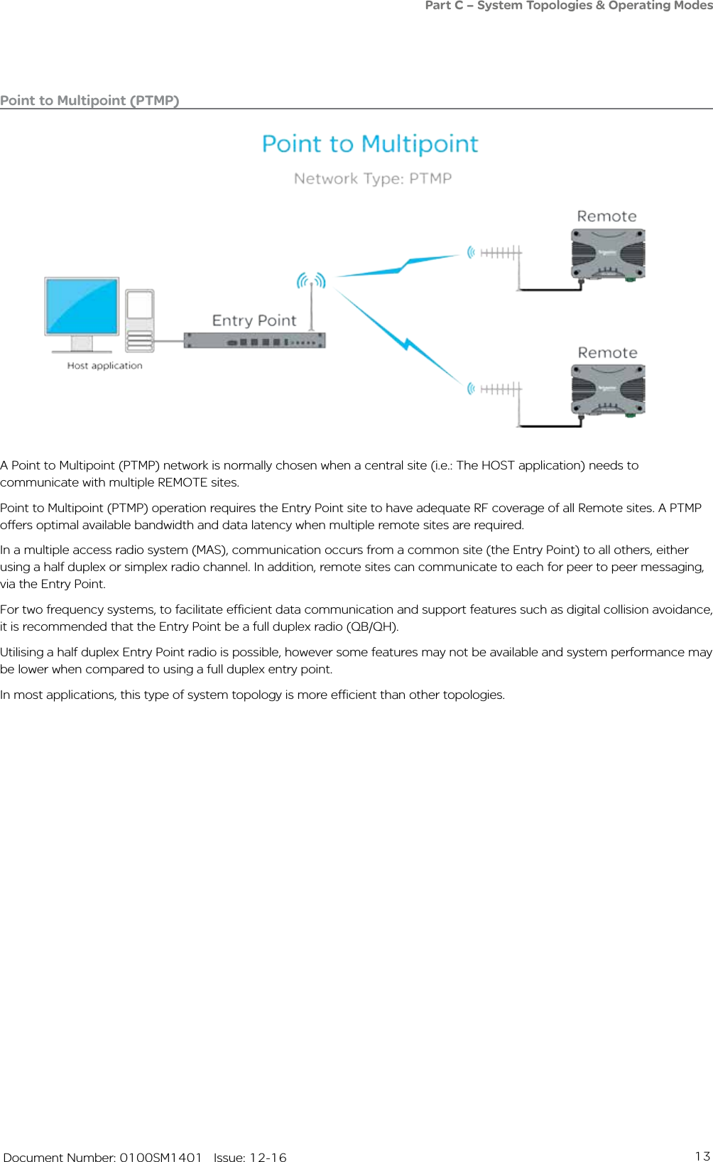
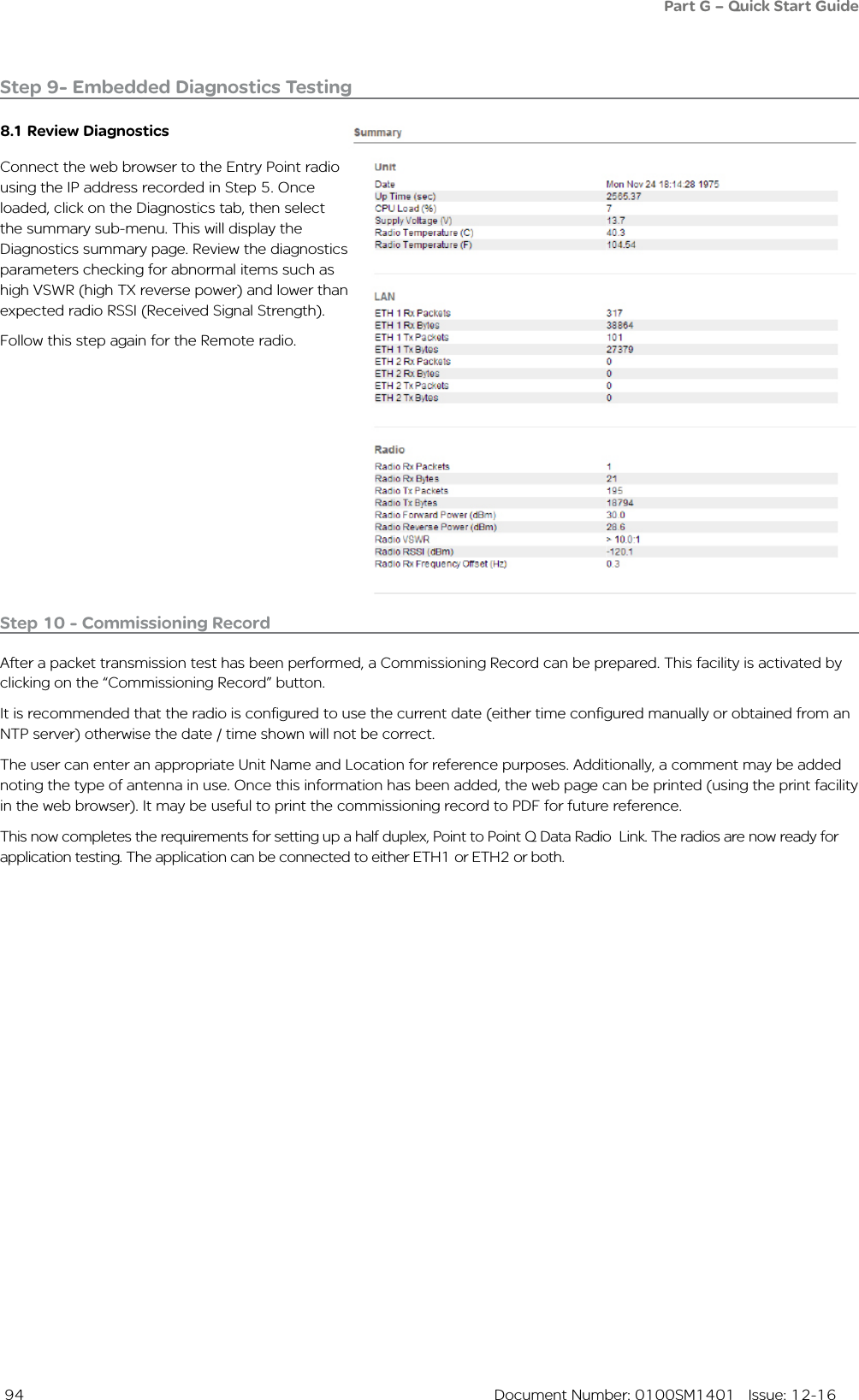
![109 Document Number: 0100SM1401 Issue: 12-16NAT - Point to Multipoint - Full Duplex Entry PointHost ApplicationIP: 192.168.0.2/24Gateway: 192.168.0.1Remote ANetwork Settings:IP: 192.168.1.1/24Router Settings:WAN IP: 10.10.10.2/24 Route Table Entries:192.168.0.0/24 10.10.10.1Port Forwarding RulesEnabled All 2300 192.168.1.2 23Ethernet DeviceIP: 192.168.1.2/24Gateway: 192.168.1.1Ethernet DeviceIP: 192.168.1.2/24Gateway: 192.168.1.1The diagram above provides an example of how to port-forward a Telnet session. In order to establish a Telnet session from the host application, to the Ethernet device connected to Remote A, the host application will have to use the following addressing: [Telnet 10.10.10.2 2300]. This address references Remote A’s WAN IP and the unique port number allocated to the Ethernet device specified within the port forwarding rule.Entry PointNetwork Settings:IP: 192.168.0.1/24Router Settings:WAN IP: 10.10.10.1/24NATDisabledPart G – Quick Start GuideRemote BNetwork Settings:IP: 192.168.1.1/24Router Settings:WAN IP: 10.10.10.3/24 Route Table Entries:192.168.0.0/24 10.10.10.1Port Forwarding RulesEnabled All 2300 192.168.1.2 23](https://usermanual.wiki/Schneider-Electric-Systems-Canada/QR150/User-Guide-3273680-Page-109.png)
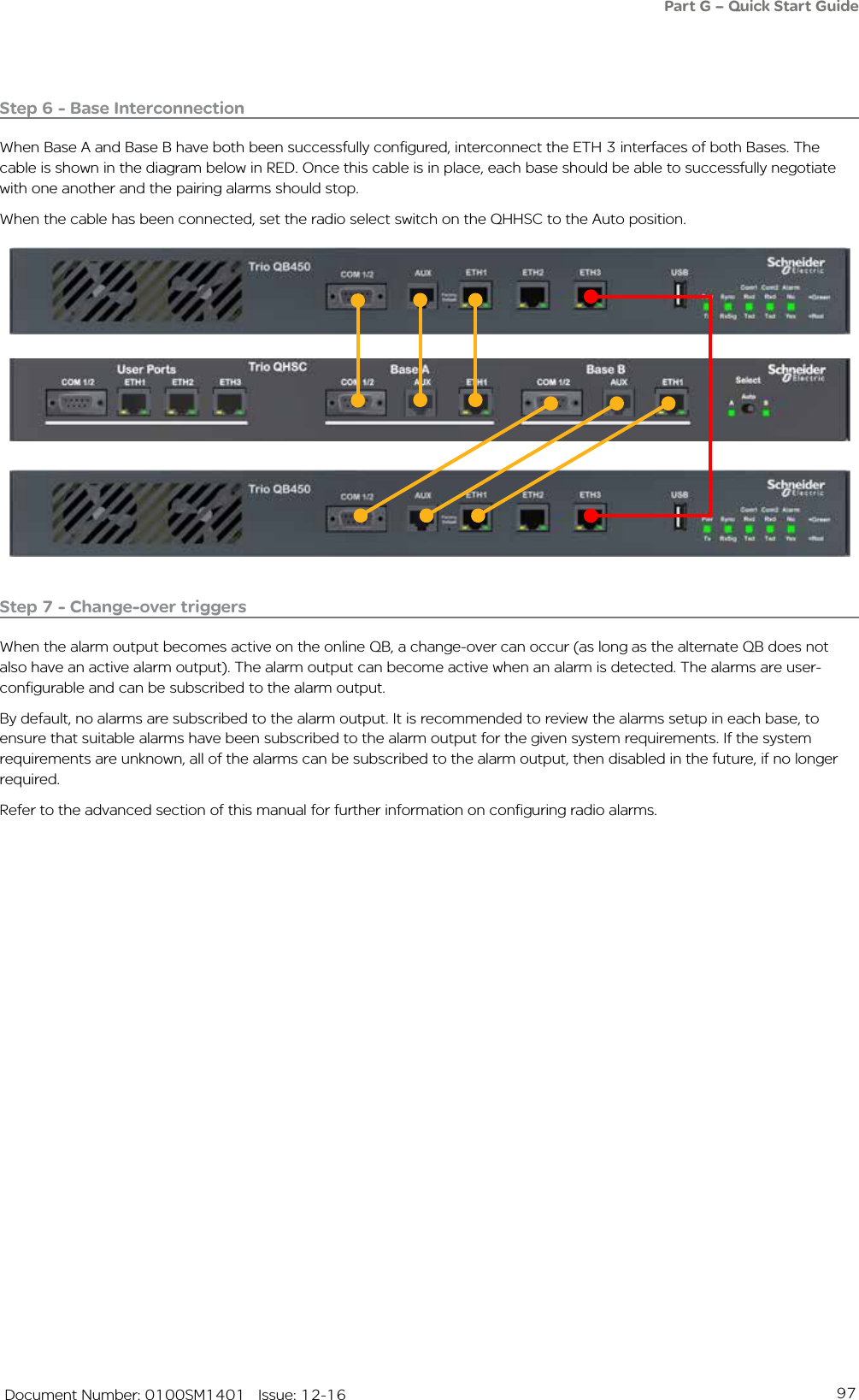
![110 Document Number: 0100SM1401 Issue: 12-16NAT - Point to Multipoint via multiple RepeatersHost ApplicationIP: 192.168.0.2/24Gateway: 192.168.0.1Entry PointNetwork Settings:IP: 192.168.0.1/24Router Settings:WAN IP: 10.10.10.1/24Route Table Entries:10.10.10.3 10.10.10.210.10.10.4 10.10.10.210.10.10.5 10.10.10.2NAT:DisabledFull Duplex RepeaterNetwork Settings:IP: 192.168.1.1/24Router Settings:WAN IP: 10.10.10.2/24Route Table Entries:10.10.10.5 10.10.10.4192.168.0.0/24 10.10.10.1NAT:Enabled Remote ANetwork Settings:IP: 192.168.1.1/24Router Settings:WAN IP: 10.10.10.3/24Route Table Entries:192.168.0.0/24 10.10.10.2Port Forwarding RulesEnabled All 2300 192.168.1.2 23Ethernet DeviceIP: 192.168.1.2/24Gateway: 192.168.1.1Ethernet DeviceIP: 192.168.1.2/24Gateway: 192.168.1.1Ethernet DeviceIP: 192.168.1.2/24Gateway: 192.168.1.1Half Duplex RepeaterNetwork Settings:IP: 192.168.1.1/24Router Settings:WAN IP: 10.10.10.4/24Route Table Entries:192.168.0.0/24 10.10.10.2Port Forwarding RulesEnabled All 2300 192.168.1.2 23Remote BNetwork Settings:IP: 192.168.1.1/24Router Settings:WAN IP: 10.10.10.5/24Route Table Entries:192.168.0.0/24 10.10.10.4Port Forwarding RulesEnabled All 2300 192.168.1.2 23The diagram above provides an example of how to port-forward a Telnet session from the Host application, to an Ethernet device shown. In order to establish a Telnet session from the host application to the Ethernet device connected to Remote A, the host application requires the following addressing: [Telnet 10.10.10.3 2300]. This address references Remote A’s WAN IP and the unique port number allocated to the Ethernet device specified within the port forwarding rule.Part G – Quick Start GuideThis topology should use Carrier detect collision avoidance.](https://usermanual.wiki/Schneider-Electric-Systems-Canada/QR150/User-Guide-3273680-Page-110.png)
![112 Document Number: 0100SM1401 Issue: 12-16Ethernet Ports (VLAN)Each Ethernet port can be independently configured to operate in one of two modes: Access or Trunk.Access: a port in access mode will process un-tagged packets from the Ethernet interface, append the corresponding Port VLAN ID (PVID) and send the packets over the radio channel. When a packet is received on the radio channel, the packet’s VLAN tag will be examined, and if it matches the user configured PVID for any Ethernet port on the radio, the tag will be removed and sent out the corresponding port. A port configured in access mode, requires a Port VLAN ID (PVID).Access ports configured with a PVID which match the management services VLAN will provide access to internal radio management services.Trunk: a port in trunk mode will transmit tagged VLAN packets from the Ethernet interface over the radio channel. If an un-tagged packed is received on the port, it will be discarded.Filtering can be applied to a trunk port, to allow only select VLAN IDs to pass through the port.Ingress Filtering, when enabled, applies filtering on VLAN packets processed on any Ethernet port configured as a trunk port. The filter will discard all VLAN tagged packets which are not found within the membership table (for the corresponding port) while, allowing VLAN tagged packets within the membership table to be sent over the radio channel. When Disabled, the Ethernet interface will pass all tagged VLAN packets over the radio channel.MembershipVLAN Membership: For trunked ports with ingress filtering enabled, VLAN IDs not defined in the table are discarded.• State: [Enable] or [Disable] the VLAN• VID: VLAN ID (1-4094).• ETH1: Include ETH1 in this VLAN. Can not be enabled if ETH1 is an access port.• ETH2: Include ETH2 in this VLAN. Can not be enabled if ETH2 is an access port.• Description: Description of the VLAN (128 Characters Max).Part G – Quick Start Guide](https://usermanual.wiki/Schneider-Electric-Systems-Canada/QR150/User-Guide-3273680-Page-112.png)
![113 Document Number: 0100SM1401 Issue: 12-16VLAN - PTMP via RepeaterThe following Diagrams are designed to provide VLAN configuration information on typical topologies. The channel bandwidth and Tx/Rx frequencies are not shown within the diagrams, as they depend on the user’s license.The following examples require a prerequisite understanding of VLAN functionality. Example 1: Access PortThe following example shows the configuration of VLAN required to isolate different hosts residing on the same network.Part G – Quick Start Guide[VLAN 1] Network Management[VLAN 2] SCADA ControlUn-Tagged packetsEntry Point configurationVLAN:Management VLAN ID: 1ETH1 Mode: AccessETH1 PVID: 1ETH2 Mode: AccessETH2 PVID: 2ETH1ETH2Network ManagementSCADA ControlETH2ETH2The Network Management Host is connected to the ETH1 interface of the Entry Point radio. Via this interface, the Network Management Host will reside on VLAN 1 (over the radio network). As the Management VLAN ID of each radio is a member of VLAN 1, the Network Management Host will have access to radio services including: HTTP/S, Telnet, SSH, SNMP & eDiags.The SCADA Control Host is connected to the ETH2 interface of the Entry Point radio. Via this interface, the SCADA Control Host will reside on VLAN 2 (over the radio network). As the remote radio’s ETH2 interface is a member of VLAN 2, the SCADA Control Host will have access to the SCADA devices connected to the ETH2 interface of the remote radios.In this example, the Network Management Host does not have access to the SCADA devices (as they are connected to the ETH2 interface of the remote radios, which is a member of VLAN 2), while the SCADA Control Host does not have access to radio services, as they reside on VLAN 1.ETH1 Optional connection for radio system diagnosticsFull Duplex Repeater configurationVLAN:Management VLAN ID: 1Remote A configurationVLAN:Management VLAN ID: 1ETH2 Mode: AccessETH2 PVID: 2Remote B configurationVLAN:Management VLAN ID: 1ETH1 Mode: AccessETH1 PVID: 1ETH2 Mode: AccessETH2 PVID: 2](https://usermanual.wiki/Schneider-Electric-Systems-Canada/QR150/User-Guide-3273680-Page-113.png)
![114 Document Number: 0100SM1401 Issue: 06-16Example 2: Trunk PortThe following example shows the configuration of VLAN required to allow pre-tagged VLAN packets, to be sent over the radio network.Part G – Quick Start Guide[VLAN 1] Network Management[VLAN 2] SCADA ControlUn-Tagged packetsETH1Network ManagementSCADA ControlETH2ETH2Ethernet SwitchWANEthernet SwitchEntry Point VLAN configurationVLAN:Management VLAN ID: 1ETH1 Mode: TrunkETH1 Ingress Filtering: DisabledETH1 Optional connection for radio system diagnosticsPre-tagged VLAN packets are sent into each port of the entry point radio. This example shows managed Ethernet switches performing the VLAN tagging.The entry point radio is configured to trunk VLAN 1 & VLAN 2 on the ETH1 interface.As packets from the Network Management Host are being tagged on VLAN 1 (by the managed switch) and the Management VLAN ID of each radio is a member of VLAN 1, the Network Management Host will have access to radio services including: HTTP/S, Telnet, SSH, SNMP & eDiags. As packets from the SCADA Control Host are being tagged on VLAN 2 (by the managed switch) and the remote radio’s ETH2 interface is a member of VLAN 2, the SCADA Control Host will have access to the SCADA devices connected to the ETH2 interface of the remote radios.In this example, the Network Management Host does not have access to the SCADA devices (as they are connected to the ETH2 interface of the remote radios, which is a member of VLAN 2), while the SCADA Control Host does not have access to radio services, as the managed switch has tagged them on VLAN 1.Example 3: Trunk Port & Access PortA mixture of the preceding examples can be implemented on the radio network. In this circumstance, the trunk port will not allow the VLAN which the Access port is a member of, unless specified in the membership table.Remote A configurationVLAN:Management VLAN ID: 1ETH2 Mode: AccessETH2 PVID: 2Remote B configurationVLAN:Management VLAN ID: 1ETH1 Mode: AccessETH1 PVID: 1ETH2 Mode: AccessETH2 PVID: 2](https://usermanual.wiki/Schneider-Electric-Systems-Canada/QR150/User-Guide-3273680-Page-114.png)
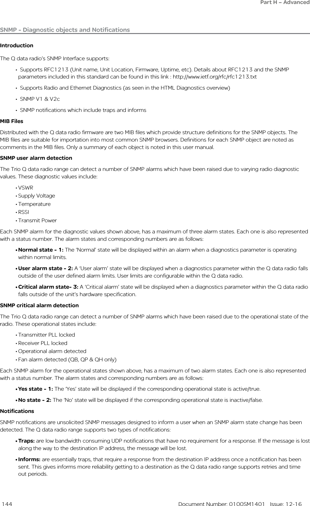
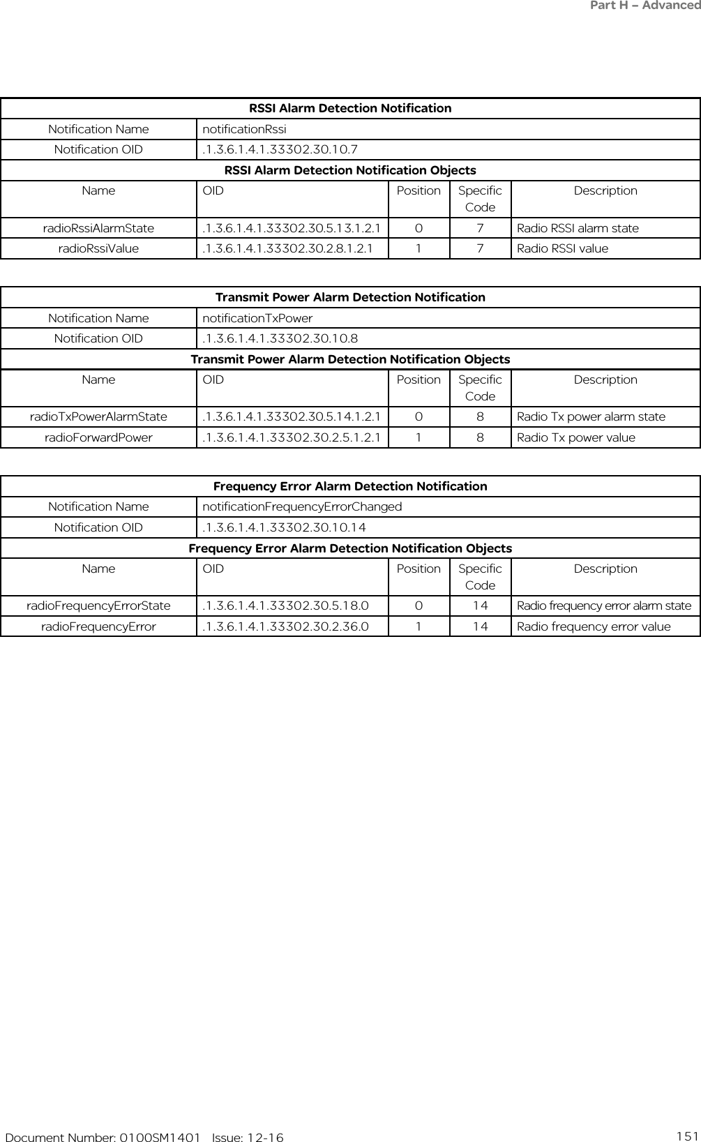
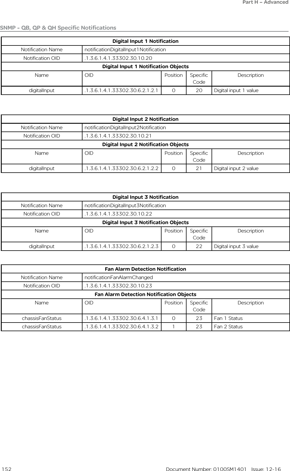
![145 Document Number: 0100SM1401 Issue: 12-16Summary of SNMP MIB Objects Supported Object name Object Identifier (OID) Syntax Object descriptionGeneral Group:serialNumber .1.3.6.1.4.1.33302.30.1.1.0 String Serial number of the Q data radiomodelNumber .1.3.6.1.4.1.33302.30.1.2.0 String Model number of the Q data radiohardwareRevision .1.3.6.1.4.1.33302.30.1.3.0 String Hardware revision of the Q data radiofirmwareRevision .1.3.6.1.4.1.33302.30.1.5.0 String The firmware revision the Q data radiodate .1.3.6.1.4.1.33302.30.1.6.0 String The date as reported by the Q data radiotime .1.3.6.1.4.1.33302.30.1.7.0 String The time as reported by the Q data radioutcTimeOffset .1.3.6.1.4.1.33302.30.1.8.0 String Time offset from UTC for the Q data radio’s local time zoneupTime .1.3.6.1.4.1.33302.30.1.9.0 String The uptime of the Q data radioprimaryNtpServer .1.3.6.1.4.1.33302.30.1.10.0 String Primary Network Time Protocol (NTP) domain namecpuLoad .1.3.6.1.4.1.33302.30.1.11.0 Integer Average CPU utilisation (%) for the past 15 minutessupplyVoltage .1.3.6.1.4.1.33302.30.1.12.0 Integer Supply Voltage of the Q data radio in mVTemperatureTable .1.3.6.1.4.1.33302.30.1.13.0 Table Table of radio temperatures.ipAddress .1.3.6.1.4.1.33302.30.1.15.0 IP Address The IP address of the Q data radio.Radio Group:radioReceivedPackets .1.3.6.1.4.1.33302.30.2.3.0 Counter Number of packets received from over the radio linkradioTrasnmittedPackets .1.3.6.1.4.1.33302.30.2.4.0 Counter Number of packets transmitted over the radio linkradioForwardPowerTable .1.3.6.1.4.1.33302.30.2.5.0 Table Table of radio forward powers.radioReversePowerTable .1.3.6.1.4.1.33302.30.2.6.0 Table Table of radio Reverse powers.radioVswrTable .1.3.6.1.4.1.33302.30.2.7.0 Table Table of radio VSWR’sradioRssiTable .1.3.6.1.4.1.33302.30.2.8.0 Table Table of RSSI values.radioDataRate .1.3.6.1.4.1.33302.30.2.15.0 Integer The over-the-air data rate of the Q data radio.[Dynamic(0), 8000bps(1),14000bps(2), 16000bps(3), 24000bps(4), 28000bps(5), 32000bps(6), 42000bps(7), 56000bps(8), 9600bps(9), 19200bps(10), 2400bps(11), 4800bps(12)]txFrequency .1.3.6.1.4.1.33302.30.2.18.0 Integer Radio’s transmit frequency (Hz).rxFrequency .1.3.6.1.4.1.33302.30.2.19.0 Integer Radio’s receive frequency (Hz).muteThreshold .1.3.6.1.4.1.33302.30.2.20.0 Integer Radio’s mute threshold (dBm).rxGoodFrameCount .1.3.6.1.4.1.33302.30.2.23.0 Counter Good frames received.rxGoodByteCount .1.3.6.1.4.1.33302.30.2.24.0 Counter Good bytes received.rxBadFrameCount .1.3.6.1.4.1.33302.30.2.25.0 Counter Bad frames received.rxAverageGoodFrameSize .1.3.6.1.4.1.33302.30.2.26.0 Integer Average received good frame size.rxAverageFrameRate .1.3.6.1.4.1.33302.30.2.27.0 Integer Average receive frame rate.rxChannelOccupancy .1.3.6.1.4.1.33302.30.2.28.0 Integer Receive channel occupancy.rxSlidingChannelOccupancy .1.3.6.1.4.1.33302.30.2.29.0 Integer Sliding channel occupancy.txByteCount .1.3.6.1.4.1.33302.30.2.31.0 Counter Transmitted byte counter.txFrameCount .1.3.6.1.4.1.33302.30.2.32.0 Counter Transmit frame count.txAverageFrameSize .1.3.6.1.4.1.33302.30.2.33.0 Integer Transmit average frame size.txAverageFrameRate .1.3.6.1.4.1.33302.30.2.34.0 Integer Transmit average frame rate.radioFrequencyError .1.3.6.1.4.1.33302.30.2.36.0 Integer Radio frequency error (Hz).Part H – Advanced](https://usermanual.wiki/Schneider-Electric-Systems-Canada/QR150/User-Guide-3273680-Page-145.png)
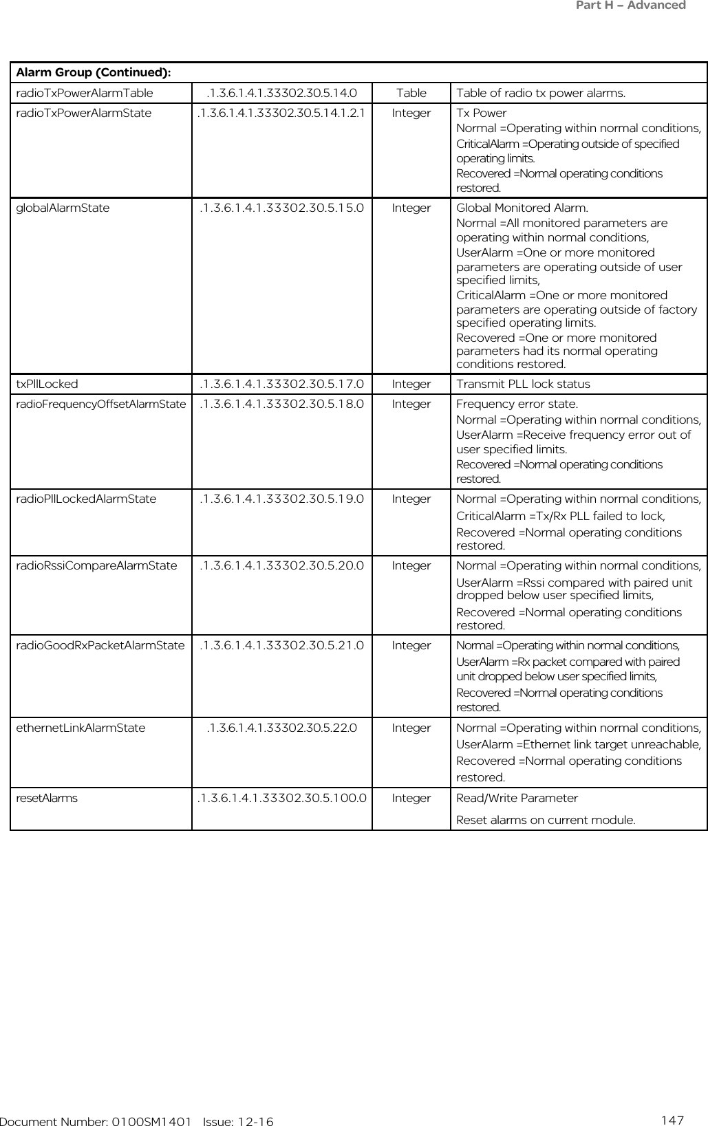
![146 Document Number: 0100SM1401 Issue: 12-16Object name Object Identifier (OID) Syntax Object descriptionSecurity Group:snmpVersion .1.3.6.1.4.1.33302.30.3.1.0 Integer Default SNMP versionconsoleLoginStatus1 .1.3.6.1.4.1.33302.30.3.2.0 Integer Console login status for COM1consoleLoginStatus2 .1.3.6.1.4.1.33302.30.3.3.0 Integer Console login status for COM2numberOfActiveTelnetSessions .1.3.6.1.4.1.33302.30.3.4.0 Integer Number of active Telnet sessionsTelnetSessionTable .1.3.6.1.4.1.33302.30.3.5.0 Table Table of Telnet and Ssh sessionsencryptionStatus .1.3.6.1.4.1.33302.30.3.11.0 Integer Encryption statusETH Group:ethInterfaceTable .1.3.6.1.4.1.33302.30.4.1.0 Table Table of network interfacesinterfaceName .1.3.6.1.4.1.33302.30.4.1.1.2.x String Ethernet interface (row) name (where x is the Ethernet interface - 1 [ETH1], 2 [ETH2] or 3[(ETH3])interfaceStatus .1.3.6.1.4.1.33302.30.4.1.1.3.x Integer Ethernet interface (row) name (where x is the Ethernet interface - 1 [ETH1], 2 [ETH2] or 3[(ETH3])interfaceSpeed .1.3.6.1.4.1.33302.30.4.1.1.4.x Integer Ethernet interface (row) name (where x is the Ethernet interface - 1 [ETH1], 2 [ETH2] or 3[(ETH3])interfaceMode .1.3.6.1.4.1.33302.30.4.1.1.5.x Integer Ethernet interface (row) name (where x is the Ethernet interface - 1 [ETH1], 2 [ETH2] or 3[(ETH3])Part H – AdvancedAlarm Group:operationalAlarm .1.3.6.1.4.1.33302.30.5.1.0 Integer Operational alarmrxPllLocked .1.3.6.1.4.1.33302.30.5.2.0 Integer Receiver PLL lock statusradioVswrAlarmTable .1.3.6.1.4.1.33302.30.5.10.0 Table Table of VSWR alarmsradioVswrAlarmState .1.3.6.1.4.1.33302.30.5.10.1.2.1 Integer High VSWRNormal =Operating within normal conditions,UserAlarm =Operating outside of user specified limits,CriticalAlarm =Operating outside of specified operating limits.Recovered =Normal operating conditions restored.externalSupplyVoltageAlarmState .1.3.6.1.4.1.33302.30.5.11.0 Integer External supply voltageNormal =Operating within normal conditions,UserAlarm =Operating outside of user specified limits,CriticalAlarm =Operating outside of factory specified operating limits.Recovered =Normal operating conditions restored.temperatureAlarmState .1.3.6.1.4.1.33302.30.5.12.0 Integer Internal temperature.Normal =Operating within normal conditions,UserAlarm =Operating outside of user specified limits,CriticalAlarm =Operating outside of specified operating limits.Recovered =Normal operating conditions restored.radioRssiAlarmTable .1.3.6.1.4.1.33302.30.5.13.0 Table Table of radio RSSI alarm statesradioRssiAlarmState .1.3.6.1.4.1.33302.30.5.13.1.2.1 Integer RSSINormal =Operating within normal conditions,UserAlarm =Operating outside of user specified limits.Recovered =Normal operating conditions restored.](https://usermanual.wiki/Schneider-Electric-Systems-Canada/QR150/User-Guide-3273680-Page-146.png)
![153 Document Number: 0100SM1401 Issue: 12-16Part H – AdvancedConfiguration Save / Load (WUI)Any single radio configuration can be saved to a configuration file. The configuration file can be used to duplicate a radio’s configuration or as the basis for another remote radio’s configuration. To save or load a configuration file, browse to Setup -> Save / Load.Save ConfigurationAs of firmware version 1.5.0, there are two modes for saving a configuration file:• Standard: Saves a configuration file including standard configuration parameters (i.e. Network, Radio, COM1/2, etc).• Standard with Passwords: (Only available when logged in with unrestricted access) Saves a standard configuration file which includes secure information. Secure information includes:- Configuration Security [Enable/Disable]- HTTP/HTTPS [Enable/Disable] - Telnet/SSH [Enable/Disable]- AES [Enable/Disable]- SNMP community Strings- User Administration information (passwords hashed).The ‘Standard with Passwords’ saved configuration file allows an unrestricted user to duplicate the security information saved from one radio into another radio. NOTICEPOTENTIAL SECURITY RISKA conguration le saved with passwords should be stored in a secure location and only given to those with unrestricted access. The security information in the conguration le is not encrypted (except for user passwords, which are hashed)Failure to follow these instructions can result in cyber security vulnerabilitiesLoad ConfigurationTo load a configuration file, select the ‘Choose File’ button, browse to a directory where a configuration has been previously saved and select open. Once the file is selected, select the ‘Load’ button.Once the configuration file has loaded, press the ‘Activate’ button.Once the Saved configuration mode has been selected, select the ‘Save’ button.When a configuration file is saved, the radio will take an image of the current active configuration and create a ‘.cfg’ file. Configuration changes which have not been activated will not be saved.NOTICEPOTENTIAL SECURITY RISKWhen saving condential information such as user names and passwords, use a secure connection to the conguration page such as HTTPS or SSH.Failure to follow these instructions can result in cyber security vulnerabilities.NOTICEPOTENTIAL SECURITY RISKWhen loading condential information such as user names and passwords, use a secure connection to the conguration page such as HTTPS or SSH.Failure to follow these instructions can result in cyber security vulnerabilities.](https://usermanual.wiki/Schneider-Electric-Systems-Canada/QR150/User-Guide-3273680-Page-153.png)