Schneider Electric 097742 Wireless Thermal Sensor User Manual FM
Schneider Electric Wireless Thermal Sensor FM
User manual
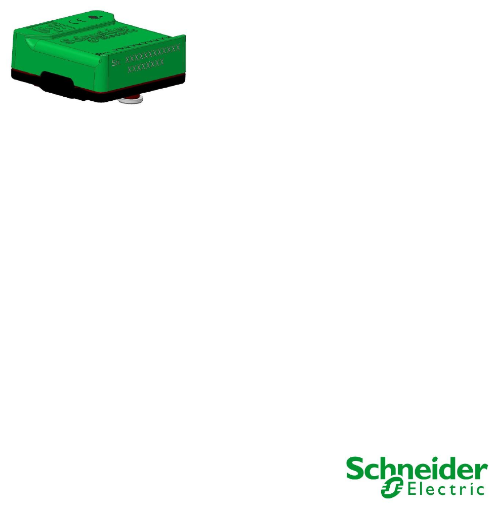
Easergy
TH110
Installation and Operation Manual
NVE62740 Rev D
07/2016
www.schneider-electric.com

TH110 Legal
2
1 Legal Information
The Schneider Electric brand and any registered trademarks of
Schneider Electric Industries SAS referred to in this guide are the
sole property of Schneider Electric SA and its subsidiaries. They may
not be used for any purpose without the owner's permission, given in
writing. This guide and its content are protected, within the meaning
of the French intellectual property code (Code de la propriété
intellectuelle français, referred to hereafter as "the Code"), under the
laws of copyright covering texts, drawings and models, as well as by
trademark law. You agree not to reproduce, other than for your own
personal, noncommercial use as defined in the Code, all or part of
this guide on any medium whatsoever without Schneider Electric's
permission, given in writing. You also agree not to establish any
hypertext links to this guide or its content. Schneider Electric does not
grant any right or license for the personal and noncommercial use of
the guide or its content, except for a non-exclusive license to consult
it on an "as is" basis, at your own risk. All other rights are reserved.
Electrical equipment should be installed, operated, serviced and
maintained only by qualified personnel. No responsibility is assumed
by Schneider Electric for any consequences arising out of the use of
this material.
As standards, specifications and designs change from time to time,
please ask for confirmation of the information given in this publication.

TH110 Table of contents
3
1 LEGAL INFORMATION ............................................................................................................................... 2
2 IMPORTANT NOTES ................................................................................................................................... 4
2.1 GENERAL FOR SYMBOLS ................................................................................................................................. 4
2.2 DIFFUSION ..................................................................................................................................................... 4
3 SAFETY RULES .......................................................................................................................................... 5
4 CAUTIONS ................................................................................................................................................... 6
5 NOTICES ...................................................................................................................................................... 6
6 INSTALLATION ........................................................................................................................................... 7
7 OPERATION .............................................................................................................................................. 10
7.1 GENERAL .................................................................................................................................................... 10
7.2 PRODUCT TECHNICAL DATASHEET................................................................................................................. 10
8 MAINTENANCE ......................................................................................................................................... 12
8.1 GENERAL .................................................................................................................................................... 12
8.2 PERIODICAL MAINTENANCE ........................................................................................................................... 12
9 ANOMALIES / SOLUTIONS TABLE ......................................................................................................... 12
10 ENVIRONNEMENTAL IMPACTS .............................................................................................................. 13
10.1 PRODUCT ENVIRONMENTAL PROFILE ........................................................................................................ 13
10.2 PRODUCT OVERVIEW .............................................................................................................................. 13
10.3 END OF LIFE ............................................................................................................................................ 13
10.4 RECYCLING ............................................................................................................................................. 13
TH110 Important notes
4
2 Important notes
Electrical equipment should be installed, operated, serviced, and maintained only by qualified
staff. Schneider Electric assumes no responsibility if the rules are not respected.
A qualified person is one who has skills and knowledge related to the construction and
operation of electrical equipments and their installation, and has received safety training to
recognize and avoid the hazards involved.
2.1 General for symbols
Read these instructions carefully, and look at the equipment to become familiar with
the device before trying to install, operate, or maintain it. The following special
messages may appear throughout this documentation or on the equipment to warn of
potential hazards or to call attention to information that clarifies or simplifies a
procedure.
The addition of this symbol to a «Danger» or «Warning» safety label indicates that an
electrical hazard exists, which will result in personal injury if the instruction are not
followed.
This is the safety alert symbol. It is used to alert you to potential personal injury hazards.
Obey all safety messages that follow this symbol to avoid possible injury or death.
This is the symbol used for wireless communication based on radio frequency
technologies. It could be combined to the safety alert symbol when a minimum distance
is required.
DANGER
DANGER indicates a hazardous situation which, if not avoided, will result in death or serious injury.
WARNING
WARNING indicates a hazardous situation which, if not avoided, could result in death or serious injury.
CAUTION
CAUTION indicates a hazardous situation which, if not avoided, could result in minor or moderate injury.
NOTICE
NOTICE is used to address practices not related to physical injury. The safety alert symbol shall not be used with
this signal word.
2.2 Diffusion
CAUTION
The aim of this publication is to enable the Easergy TH110 sensor to be installed correctly within validated
equipment
NOTICE
Total or partial reproduction of this manual is prohibited and only agents Schneider Electric have an exclusive right
to use.
TH110 Safety rules
5
3 Safety rules
DANGER
HAZARD OF ELECTRIC SHOCK, EXPLOSION, OR ARC FLASH
Read and understand this guide before performing any installation or maintenance with the sensor
Easergy TH110 then the guides according to the switchgear and controlgear where the Easergy TH110
will be installed to identify the associated precaution. If the installation and user guides of the switchgear
and controlgear do not cover the integration of the Easergy TH110, a contact to the manufacturer of the
switchgear is required.
All parts of this Easergy sensor have been qualified and certified according to their respective standards
and regulation and can't be replaced by any similar product not specified within this document. If the
Easergy TH110 is used in a manner not specified by this document, the protection provided by the
equipment may be impaired.
Check if the technical ratings of the Easergy sensor TH110 are adapted with the application (see § 7).
The sensor must be installed where the temperature will be lower than the IEC limits in normal operation.
Apply appropriate personal protective equipment (PPE) and follow safe electrical work practices. See
NFPA 70E or CSA Z462.
This equipment must only be installed and serviced by qualified electrical personnel.
Turn off all power supplying this equipment before working on or inside equipment.
Always use a properly rated voltage sensing device to confirm power is off.
Replace all devices, doors and covers before turning on power to this equipment.
Failure to follow these instructions will result in death or serious injury.
DANGER
EXPOSURE TO CHEMICAL AGENT
DANGER indicates a hazardous situation which, if not avoided, will result in death or serious injury.
DANGER
EXPOSURE TO RADIO FREQUENCY
Read and understand this guide before performing any installation with the sensor Easergy TH110.
The Easergy sensor is an energy harvesting and wireless communication sensor using Zigbee 2.4GHz protocol
IEEE802.15.4. The Easergy TH110 is a mobile device.
FCC: This device complies with FCC RF radiation exposure limits set forth for general population. This device must be
installed to provide a separation distance of at least 20cm from all persons and must not be co-located or operating in
conjunction with any other antenna or transmitter.
IC: This device complies with Industry Canada RF radiation exposure limits set forth for general population. This device
must be installed to provide a separation distance of at least 20cm from all persons and must not be co-located or
operating in conjunction with any other antenna or transmitter. Le présent appareil est conforme aux niveaux limites
d’exigences d’exposition RF aux personnes définies par Industrie Canada. L’appareil doit être installé afin d’offrir une
distance de séparation d’au moins 20cm avec l’utilisateur, et ne doit pas être installé à proximité ou être utilisé en
conjonction avec une autre antenne ou un autre émetteur.
Failure to follow these instructions will result in death or serious injury.
TH110 Safety rules
6
4 Cautions
CAUTION
TEMPERATURES OF NON TOUCHABLE HOT SURFACES
As the sensor can measure temperatures above 50°C, any accessibility to any de-energized part must be done
with gloves as individual protection and when the temperature of this part will be lower than 50°C.
Failure to follow these instructions can result in injury.
5 Notices
NOTICE
Before servicing the Easergy sensor TH110 shall be paired with its concentrator.
NOTICE - FCC
This device complies with Part 15 of the FCC Rules. Operation is subject to the following two conditions: (1) this
device may not cause harmful interference, and (2) this device must accept any interference received, including
interference that may cause undesired operation.
"NOTE: This equipment has been tested and found to comply with the limits for a Class B digital device, pursuant
to part 15 of the FCC Rules. These limits are designed to provide reasonable protection against harmful
interference in a residential installation. This equipment generates, uses and can radiate radio frequency energy
and, if not installed and used in accordance with the instruction, may cause harmful interference to radio
communications. However, there is no guarantee that interference will not occur in a particular installation. If this
equipment does cause harmful interference to radio or television reception which can be determined by turning
the equipment off and on, the user is encouraged to try to correct interference by one or more of the following
measures:
- Reorient or relocate the receiving antenna.
- Increase the separation between the equipment and receiver.
- Connect the equipment into an outlet on circuit different from that to which the receiver is connected.
- Consult the dealer or an experienced radio/TV technician for help
Any change or modification of the product not expressly approved by the party responsible for compliance could
void the user's authority to operate the equipment.
NOTICE - IC
Under Industry Canada regulations, this radio transmitter may only operate using an antenna of a type and
maximum (or lesser) gain approved for the transmitter by Industry Canada. To reduce potential radio interference
to other users, the antenna type and its gain should be so chosen that the equivalent isotropically radiated power
(e.i.r.p.) is not more than that necessary for successful communication.
Conformément à la réglementation d'Industrie Canada, le présent émetteur radio peut fonctionner avec une
antenne d'un type et d'un gain maximal (ou inférieur) approuvé pour l'émetteur par Industrie Canada. Dans le but
de réduire les risques de brouillage radioélectrique à l'intention des autres utilisateurs, il faut choisir le type
d'antenne et son gain de sorte que la puissance isotrope rayonnée équivalente (p.i.r.e.) ne dépasse pas
l'intensité nécessaire à l'établissement d'une communication satisfaisante.
This device complies with Industry Canada licence-exempt RSS standard(s). Operation is subject to the following
two conditions: (1) this device may not cause interference, and (2) this device must accept any interference,
including interference that may cause undesired operation of the device.
Le présent appareil est conforme aux CNR d'Industrie Canada applicables aux appareils radio exempts de
licence. L'exploitation est autorisée aux deux conditions suivantes : (1) l'appareil ne doit pas produire de
brouillage, et (2) l'utilisateur de l'appareil doit accepter tout brouillage radioélectrique subi, même si le brouillage
est susceptible d'en compromettre le fonctionnement.
TH110 Installation
7
6 Installation
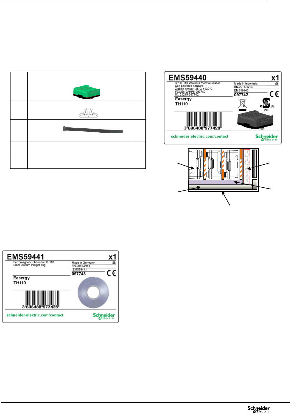
Check the delivery of the Easergy TH110 sensors
• Check that the reference printed on the label matches with the delivery and is corresponding with the
purchase order.
• Remove the Easergy TH110 sensors and accessories from the packaging.
Ref
Detail
Qty
Easergy TH110 sensor
NVE52868
3
Panduit self-locking head MTHH-C316
NVE52873
4
Fixing & self gripping tape L=565mm &
W=16mm
NVE52871
3
Quick start guide NVE61600
1
Packaging NVE52874
1
Check the delivery of the ferromagnetic ribbon
The ferromagnetic ribbon shall be ordered separately. The reference to order is EMS59441.
Remove the ferromagnetic ribbon from the packaging and check that it has not been damaged.
Pairing of the sensor Easergy TH110
Before installation, any sensor must be paired with its associated Zigbee green power access
point.
By default the sensor is in pairing mode to be paired with any opened access point as soon as
sensor is powered on.
INSTRUCTION SHEET
VELCRO

TH110 Installation
8
Installation of the sensor Easergy TH110
NOTICE : Mechanical parts
Ref 1) Thermal sensor TH110 embedding the
thermistor in contact with the measured part
Ref 2) Tie lock: Panduit MTHH-C316 A and
ferromagnetic ribbon
Ref 3) Fixing: Self gripping tape with buckle. Tape
width: 16 mm
Ref 4) Tools: Hellermann Tyton ref MK9SST or
Phoenix contact ref 1212610
DANGER
a) See clause on Safety rules §2 of
this document.
b) Check your individual protection.
Gloves for metallic parts are required in
addition of any other need by the
application.
c) Put the HV functional unit on a mode
enabling its accessibility to install the
sensor according to the customer and
Schneider Electric procedures.
1) Prepare your products and tool.
: Thermal sensor
: Tie lock and ferromagnetic ribbon
: Fixing & self gripping tape
: Tool (Phoenix) to close the ferromagnetic
ribbon
2) To note the sensor number and its
position within HV functional unit (Functional unit
number, Busbar or CB up or CB down or Cable)
and the associated phase reference. To note the
Zigbee source ID. It is used to check if the sensor
is paired with the access point (RF receiver).
3) After a check and cleaning deposit if any
over the ferromagnetic ribbon Ref 2, prepare the
length of this ferromagnetic ribbon Ref 2
according to the peripheral dimension of the
measured part + 100mm. Take one end of the
cut banding and bend back it on 13mm.
4) Take a self-locking head Panduit MTHH-
C316 and slide it the entire length of the band
until it reaches the bend.
5) Introduce the flat tail of the ferromagnetic
ribbon Ref 2 inside the Easergy TH110 through
the opening.
NOTICE
Due to a softness metallic ribbon pay attention
to avoid any deformation before any
introduction within the tie lock and the sensor
Steps 1 - 2 - 3
Steps 4 - 5
Step 6 - 7
15mm
Dimensions
TH110 Installation
9
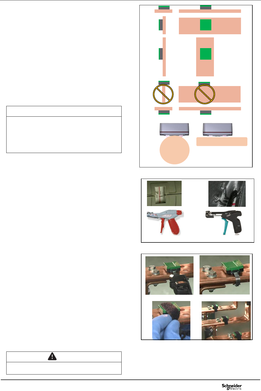
6) Install the Easergy TH110 sensor within
the HV switchgear where the thermal
measurement is required. Then bend the flat tail
of the ferromagnetic ribbon Ref 2 to close the
loop when introduced through the tie lock.
Position of the sensor:
To prioritize a top side of the flat or round bar
To prioritize horizontal installation.
The thermistor shall be at the closest
position of the connection.
The position shall be in accordance to the
installation prescribed within installation
guide of the electrical equipment.
NOTICE
Due to interlock on CB, attention shall be paid
to avoid any damage when the sensor is
installed in arms of some CB: To avoid this
potential issue the sensor shall be installed at
the bottom side of the top arms or the upper
side of the bottom arms.
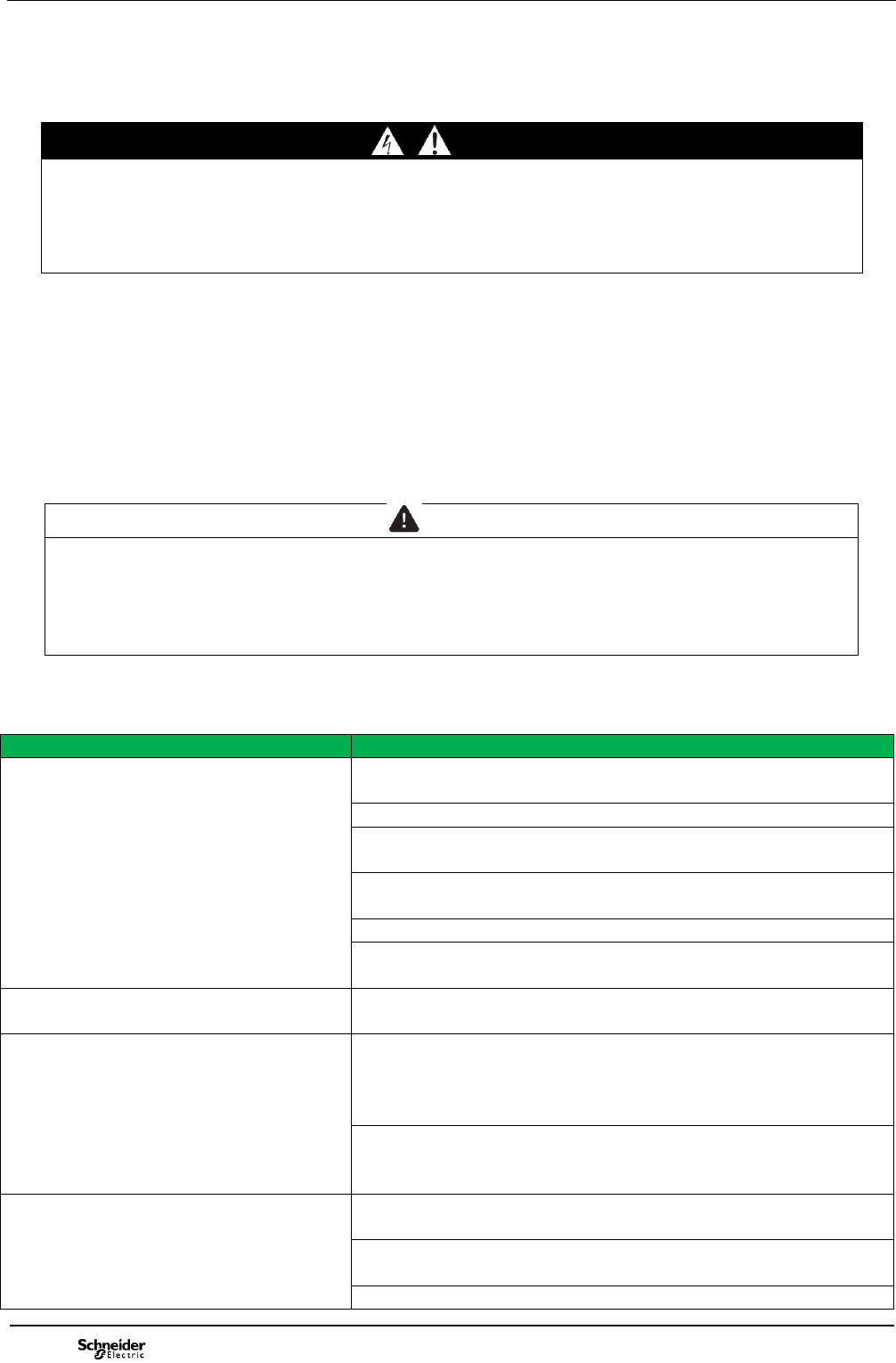
7) Introduce the flat tail inside the pliers of
the tool Ref 4: 1212610 (Phoenix Contact at right
side) or to MK9SST (Hellermann Tyton at left
side), then bend the extremity with an angle at
90° longer than 13mm.
8) The adjustable tension force is indicated
by a scale in the handle area. Set the tool Ref 4
1212610 tool at grade 1.5 or the tool MK9SST at
grade 1.5 (200N Max as tensile stress). Tense
the ferromagnetic ribbon Ref 2.
9) Finish the tensile of the ferromagnetic
ribbon Ref 2 with the tool Ref 4, and when the
tension is at the setting value, the ferromagnetic
ribbon Ref 2 is cut automatically with the tool Ref
4. The metallic ribbon can’t assure the right
tightening and must be covered by the fixing and
self gripping tape.
10) To install the fixing and self gripping tape
Ref 3 over the sensor Easergy TH110 Ref 1 and
the ferromagnetic ribbon Ref 2 introduce the
fixing and self gripping tape Ref 3 cut at the right
length within the buckle then return the tape and
tense it to avoid any sliding, then close the self
gripping tape. To finish the installation cut the
non gripped part with a scissor.
WARNING
Check the installation according to the
installation guide of the switchgear.
Step 6 - 7
MK9SST 1212610
Steps 8
Steps 9 - 10
Periphery range of
measured part: 60–300mm

TH110 Operation
10
7 Operation
7.1 General
The product Easergy TH110 is a wireless thermal sensor enabling energy harvesting and batteryless
functions. It is intended to be used within indoor high and low voltage electrical distribution products or
assemblies to monitor the temperatures of any live connection. The sensor shall be used with a
Schneider-Electric access point having the function of concentrator of sensors, using Zigbee Green
Power wireless communication protocol.
7.2 Product technical datasheet
Main
Range of product
Easergy
Product or component type
Indoor thermal sensor for wireless access point
Rated supply
Starting current: for energy harvesting 0.4A / cm of the peripheral AC
live part (Battery less)
Supply is not disturbed by temporary overvoltage within the limit of the
HV or LV switchgear.
Complementary
Voltage limit of the live and measured part
52kV
Induced voltage
15V max
Current limit of the live and measured part
5000A without exceeding the temperature rise limits
Range dimensions of live and measured part
Periphery range: 60 – 300 mm
Power consumption
20mA during radio transmission mode
2A max in sleeping mode
Wireless communication protocol
Zigbee green power at 2.4 GHz according to IEEE 802.15.4
Transmission period
60s
Connection type
See associated Zigbee concentrator (EBX 200, Sologate, E-gate,...)
Marking
CE (cf applicable Directives)
Mounting support
Direct on live part or shielded insulation part by fixing tape
Height
14 mm
Depth
31 mm
Width
31 mm
Product weight
0.015 kg
Environment
Product certifications
CB IECEE ID: FR682889
cBVus ID: CABA
FCC ID: 2AHP8-097742
IC : 21245-097742
LV Directive 2014/35/EU
EMC Directive 2004/108/EC
RE Directive 2014/53/EU (R&TTE directive 1999/5/EC)
Main standards
EN / IEC 61010 2010
UL 61010 -1 2012
ETSI EN 300238 2012 V1.9.1 (§ 3.2 R&TTE Directive)
IEEE 802.15.4 2013
Power emission
EIRP= +5dBm
Resistance to electrostatic discharge
2-4-8-15kV (Direct & Indirect contact) according to EN/IEC 61000-4-2
2-4-8-15kV (in air) according to EN/IEC 61000-4-2
Resistance to electromagnetic fields
30V/m (80MHz...5.7 GHz) according to EN/IEC 61000-4-3
20 V/m (80MHz....5.9 GHz) according to EN/IEC 61000-4-3
Resistance to conducted disturbances, induced by radio
frequency fields
20 V (0.15...80 MHz) according to EN/IEC 61000-4-6
Power frequency magnetic field immunity
1000A/m Pulse EN/IEC 61000-4-8

TH110 Operation
11
300A/m Continue EN/IEC 61000-4-8
Pulse magnetic field immunity
1000A/m Pulse EN/IEC 61000-4-9
Damped oscillatory magnetic field immunity
30A/m (0.1 & 1 MHz) EN/IEC 61000-4-10
Electrical fast transient/burst immunity
4kV 1 min EN/IEC 61000-4-4
2kV 5min (Marine) EN/IEC 61000-4-4
Damped oscillatory wave immunity
3kV (CM - 100kHz & 1MHz) EN/IEC 61000-4-18
2.5kV (CM - 3MHz, 10MHz, 30MHz) EN/IEC 61000-4-18
Surge immunity
0.5-1-2-4kV (Common mode) EN/IEC 61000-4-5
0.5-1-2-4kV (Differential mode) EN/IEC 61000-4-5
Immunity to conducted RF disturbances
30V Continuous (0 – 150kHz) EN/IEC 61000-4-16
300V Short duration (0 – 150kHz) EN/IEC 61000-4-16
Ambient air temperature for operation
-25...80°C Any live and measured parts shall be lower than IEC limits
(115°C Max)
Accuracy
+/-1°C between -25°C...80°C and +/-2°C outside the range.
Measured temperature for operation (live and measured
part)
-25...115°C for 80°C at maximum ambient temperature
-25...125°C for 40°C at maximum ambient temperature
150°C max (limited time)
Ambient air temperature for storage
-40...70°C
Relative humidity
10...95 % over a period of 24h condensation may occasionally occur
in operation
10...90 % over a period of one month condensation may occasionally
occur in operation
IP degree of protection
IP54 IEC 60529
Mechanical impact
IK07 IEC 62262 (Exposed side vs Measuring side)
Pollution degree
2 IEC 61010-1
Operating altitude
0...2000 m
Storage altitude
0...3000 m
Vibrations sinusoidal during transport
5-8Hz Ampl 7.5mm, 8-200Hz 2g, 200-500Hz 4g 20 cycles Test Fc
according to IEC 60068-2-6 (2M3 according to IEC 60721-3-2)
Vibrations random during transport
10-2000Hz 0,1g/Hz 30 min/axe according to IEC 60068-2-64
Shocks
3 shocks 2 directions 3 axes 40g 6ms (Ea) according to IEC 60068-2-
27 (2M3)
1000 shocks 2 directions 3 axes 20g 16ms (Ea) according to IEC
60068-2-27
Free falls
2m 2 free falls according to IEC 60068-2-31
Vibrations sinusoidal in operation (Installed on bar)
5-500Hz 1g 1cycle (10min) 3mm Test Fc according to IEC 60068-2-6
(3M5 according to IEC 60721-3-3)
Shocks in operation (Installed on bar)
3 shocks 3 directions 10g 11ms (Ea)according to IEC 60068-2-27
(3M5 according to IEC 60721-3-3)
Glow-wire flammability withstand
650°C
Maximum distance between sensor and the access point
100m in free field unobstructed
25m when the components are separated by one layer of metal
10m when the components are separated by two layers of metal
Offer Sustainability
Sustainable offer status
In progress
RoHS (date code: YYWW)
In progress
REACH
Reference not containing SVHC above the threshold.
Candidate list June 2015.
Product environmental profile
In progress
Product end of life instructions
In progress
TH110 Maintenance
12
8 Maintenance
8.1 General
DANGER
HAZARD OF ELECTRIC SHOCK, EXPLOSION, OR ARC FLASH
Any operation of maintenance shall be carried out under safe operation. We strongly recommend to
read the clause on Safety rules §2 of this document before any intervention.
Failure to follow these instructions will result in death or serious injury.
8.2 Periodical maintenance
If needed, contact the nearest Schneider Electric services center. We strongly recommend that you
carry out at regular intervals (at least roughly every 2 years) a few operating cycles on the switching
devices, the fixing of the Easergy TH110 sensor should be checked. If any the self gripping tape shall
be replaced, removing the old one and installing a new one as defined by the clause of this document
(Clause 5, sub-clause 4). In harsh conditions (aggressive atmosphere, dust, temperature greater than
40°C), please consult the nearest Schneider Electric services center.
CAUTION
INJURY
To replace a sensor, the tape over the sensor shall be removed and the soft ferromagnetic ribbon
can be cut with a scissor. Cutter is forbidden.
Failure to follow these instructions can result in injury or equipment damage.
9 Anomalies / solutions table
Dysfonctions
Expected solutions
Sensor is not visible by the access
point.
Check if the dysfunction is also valid for any other sensor.
Check if the sensor was already visible by the access point.
Check if the measured part is energized, to energize the
sensor.
Check if the measured part is energized with a current over
the starting current value.
Check if the sensor is known by any other access point.
Check if the distance between the sensor and the access
point according to the number of enclosure layers.
Measurement is not received by the
access point.
Check if the sensor is paired with the access point.
Measurement is near to the ambient
temperature but measurement is
abnormal compared to the
measurement of an adjacent phase.
Check if the associated phase is loaded and balanced with
the adjacent phase.
Check if the sensor is well fixed at the right position. If it is
not possible to check please, call the nearest Schneider
Electric center.
Measurement is above the limits.
Check if the ambient temperature is lower than the upper
limit of the service conditions.
Check if the load of the equipment is lower than the rated
current of the monitored equipment.
Check the measured part, applying safety procedure.

TH110 Environmental impacts
13
10 Environnemental impacts
10.1 Product environmental profile
The EIME (Environmental Impact and Management Explorer) software, version V3, and its database,
version 5.4 were used to assess the product environmental profile (PEP). The assumed service life of
the product is 20 years with an utilization rate based on the mission profile of the Easergy TH110 and
the electrical power model used is European. The scope of the analysis was limited to the Easergy
TH110 sensor and its accessories to be supplied and fixed. The environmental impacts were
analysed for the Manufacturing (M) phases, including the processing of raw materials, and for the
Distribution (D) and Utilisation (U) phases. Easergy TH110 is compliant with the RoHS directive.
RoHS restricts the use of six hazardous materials in the manufacture of various types of electronic
and electrical equipment.
10.2 Product Overview
The range is RoHS compliant: as the product of the range are designed in accordance with the RoHS
Directive (European Directive 2002/95/EC of 27 January 2003), they can be incorporated without any
restriction within an assembly or an installation submitted to this Directive. RoHS restricts the use of
six hazardous materials in the manufacture of various types of electronic and electrical equipment.
Easergy TH110 is compliant with the RoHS directive.
10.3 End of life
At end of life, the products of the Easergy TH110 sensor shall be dismantled to facilitate the recovery
of the various constituent materials.
10.4 Recycling
Schneider Electric is committed to a long term environmental approach. As part of this, the Easergy
TH110 sensor has been designed to be environmentally friendly, notably in terms of the product’s
recyclability. The materials used are identified in product environmental profile (PEP) analysis and
easily separable. It has been carried out in conformity with ISO 14040 “Environmental management:
life cycle assessment - principle and framework”.
At the end of its life, Easergy TH110 can be processed, recycled and its materials recovered in
conformity with the draft European regulations on the end-of-life of electronic and electrical products.

TH110 Personal notes
14

Schneider Electric
35 rue Joseph Monier
92500 Rueil Malmaison – France
Phone: +33 (0) 1 41 29 70 00
www.schneider-electric.com
As standards, specifications, and designs change from time
to time, please ask for confirmation of the information given
in this publication.
© 2016 Schneider Electric. All rights reserved.
NVE62740 Rev D
This document has been
printed on recycled paper