Schneider Electric 1021472 RF Gateway User Manual Clipsal RF Gateway
Schneider Electric (Australia) Pty. Ltd. RF Gateway Clipsal RF Gateway
Exhibit 8
Clipsal® RF Gateway
SLC5800WCGD for Use With C-Bus™ Wired Networks and
Clipsal® RF Wireless Control Systems
Instruction Bulletin
Retain for future use.
Clipsal® RF Gateway 63249-420-273A3
Instruction Bulletin 02/2009
2 © 2009 Schneider Electric. All Rights Reserved.
HAZARD CATEGORIES AND SPECIAL SYMBOLS
Read these instructions carefully and look at the equipment to become
familiar with the device before trying to install, operate, service, or maintain it.
The following special messages may appear throughout this bulletin or on
the equipment to warn of potential hazards or to call attention to information
that clarifies or simplifies a procedure.
ANSI Symbols Table
Danger indicates an immediately hazardous situation which, if not
avoided, will result in death or serious injury.
WARNING
Warning indicates a potentially hazardous situation which, if not
avoided, can result in death or serious injury.
Caution indicates a potentially hazardous situation which, if not
avoided, can result in minor or moderate injury.
Caution, used without the safety alert symbol, indicates a
potentially hazardous situation which, if not avoided, can result in
property damage or improper operation.
NOTE: Provides additional information to clarify or simplify a procedure.
PLEASE NOTE
Electrical equipment should be installed, operated, serviced, and maintained
only by qualified personnel. This document is not intended as an instruction
manual for untrained persons. No responsibility is assumed by Square D for
any consequences arising out of the use of this manual.

63249-420-273A3 Clipsal® RF Gateway
02/2009 Instruction Bulletin
© 2009 Schneider Electric. All Rights Reserved. 3
Class B FCC Statement
This device complies with Part 15 of the FCC Rules. Operation is
subject to the following two conditions: (1) this device may not cause
harmful interference, and (2) this device must accept any
interference received, including interference that may cause
undesired operation.
This equipment has been tested and found to comply with the limits
for a Class B digital device, pursuant to Part 15 of the FCC Rules.
These limits are designed to provide reasonable protection against
harmful interference in a residential installation. This equipment
generates, uses, and can radiate radio frequency energy and, if not
installed and used in accordance with the instructions, may cause
harmful interference to radio communications. However, there is no
guarantee that interference will not occur in a particular installation.
If this equipment does cause harmful interference to radio or
television reception, which can be determined by turning the
equipment off and on, the user is encouraged to try to correct the
interference by one or more of the following measures:
Reorient or relocate the receiving antenna.
Increase the separation between the equipment and receiver.
Connect the equipment into an outlet on a circuit different from that to
which the receiver is connected.
Consult the dealer or an experienced radio/TV technician for help.
Changes or modifications to this device that are not expressly
approved by Schneider Electric could void the user's authority to
operate this equipment.

Clipsal® RF Gateway 63249-420-273A3
Instruction Bulletin 02/2009
4 © 2009 Schneider Electric. All Rights Reserved.
ABOUT THE RF GATEWAY
The Clipsal® RF Gateway provides a C-Bus™ protocol
communication bridge between a single Clipsal® RF wireless
system and a single C-Bus wired network.
Using the Gateway, Clipsal RF wireless systems and C-Bus wired
networks can communicate and interact with each other. The
Gateway requires C-Bus Toolkit for setup.
Both network types use the same C-Bus protocol commands.
The Gateway allows:
Control of a RF wireless system by scheduling or inputting
controls from units on a C-Bus wired network or from software.
Control of output units and electrical loads in one network type
from input units in the other network type.
63249-420-273A3 Clipsal® RF Gateway
02/2009 Instruction Bulletin
© 2009 Schneider Electric. All Rights Reserved. 5
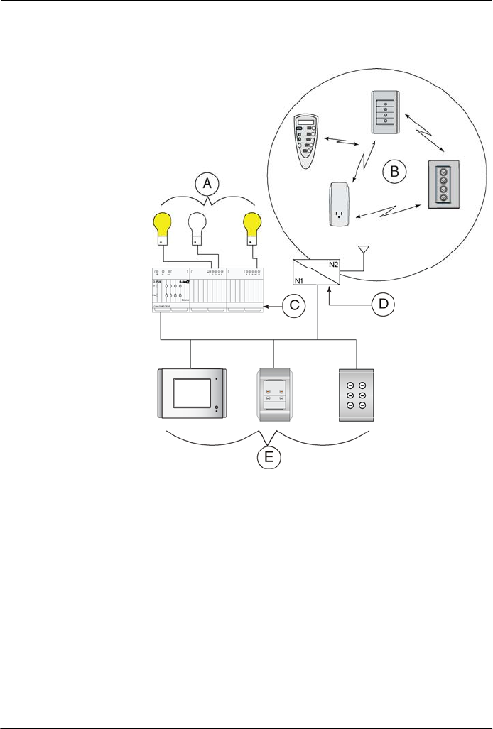
Figure 1: Clipsal RF Gateway – Typical links between wired and wireless
networks
KEY:
A. Loads (e.g., lights)
B. RF Wireless System:
includes input and output
units (e.g., RF keypads, RF
remotes, and RF plug
adaptors)
C. Wired output units (e.g.,
Dimmer)
D. RF Gateway
E. Wired input units (e.g.,
touch screens, keypads, and
occupancy sensors)
About Clipsal® RF Wireless Systems
Clipsal® RF Wireless Wall Units include Switches, leading edge
Dimmers, and Scene Controllers. The units are designed to replace
standard wall switches and dimmers. Each Switch and Dimmer
controls one load (lights or other appliances connected to its output).
Wall Units can be operated by RF Wireless remote control, and
have learn and scene capability.

Clipsal® RF Gateway 63249-420-273A3
Instruction Bulletin 02/2009
6 © 2009 Schneider Electric. All Rights Reserved.
Before You Begin
Before you begin to set up a unit, verify that your order is complete
by comparing the contents of the package with the appropriate items
in the table below. Also verify that the catalog number on the box
label matches your order.
Contents of the Box
Table 1: Contents of the Box
Part Number Description Quantity
SLC5800WCGD RF Gateway 1
Adhesive feet 4
C-Bus Network cable, 15.7 in. (400 mm) 1
63249-420-273A3 Clipsal® RF Gateway
02/2009 Instruction Bulletin
© 2009 Schneider Electric. All Rights Reserved. 7
SAFETY PRECAUTIONS
This section contains important safety precautions that must be
followed before attempting to install or maintain electrical equipment.
Carefully read and follow the safety precautions below.
HAZARD OF ELECTRIC SHOCK, EXPLOSION, OR ARC FLASH
Apply appropriate personal protective equipment (PPE) and
follow safe electrical work practices. See NFPA 70E.
This equipment must be installed and serviced by qualified
electrical personnel.
Turn off all electrical power supplying this equipment before
working on or inside the equipment.
Always use a properly rated voltage sensing device to confirm
that power is off.
Replace all devices, doors, and covers before turning on power
to this equipment.
Failure to follow these instructions will result in death or
serious injury.
Clipsal® RF Gateway 63249-420-273A3
Instruction Bulletin 02/2009
8 © 2009 Schneider Electric. All Rights Reserved.
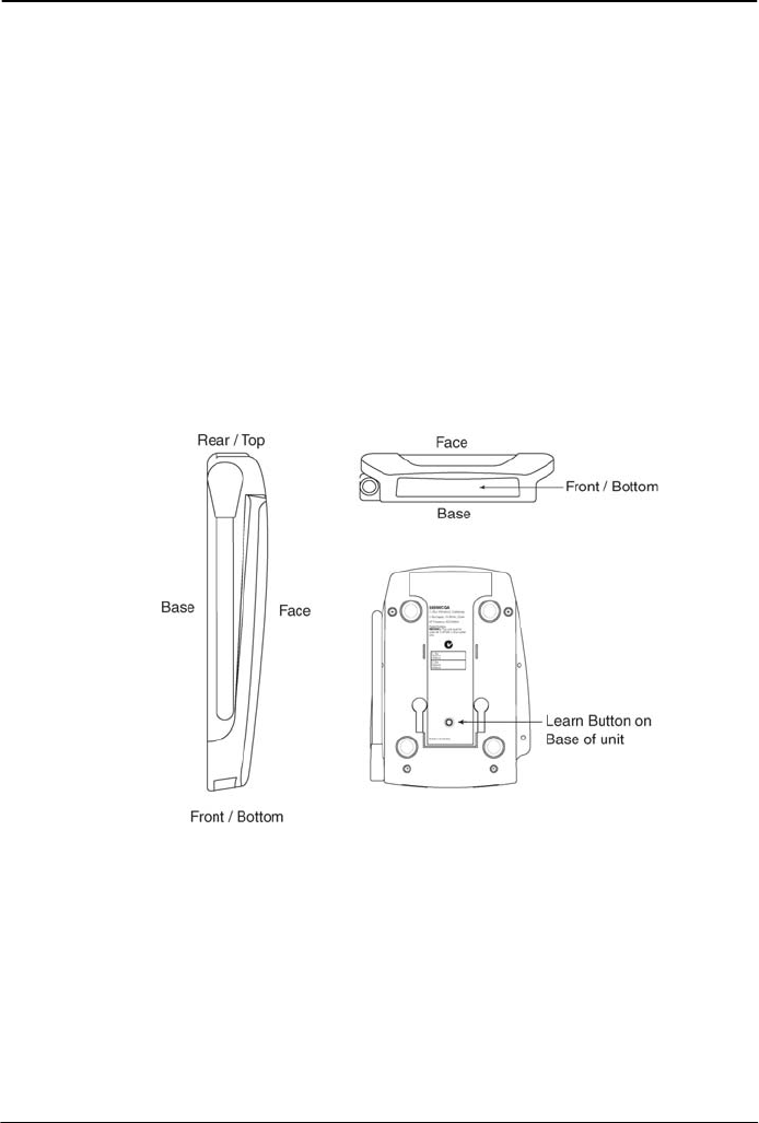
INSTALLATION INSTRUCTIONS
The RF Gateway can be installed horizontally or vertically. Either
installation should allow for access to the Learn button on the base
of the unit.
If placing the unit horizontally, you may attach the adhesive feet
(provided) to the base of the unit to prevent the unit from sliding or
scratching the surface.
If mounting the device on a wall, use the keyhole cutouts on the
base of the unit. These have 1.6 inch (40 mm) mounting centers.
Position the antenna for desired reception.
To remove the unit from the wall, slide it up and pull it off of the
screws.
Figure 2: RF Gateway Orientation
63249-420-273A3 Clipsal® RF Gateway
02/2009 Instruction Bulletin
© 2009 Schneider Electric. All Rights Reserved. 9
Network Considerations
The RF Gateway can draw 32 mA from the C-Bus network.
Determine the total network current load and verify that there will be
enough C-Bus power to support all connected devices. Also verify
that the amount of available power per C-Bus network is no more
than 2A.
Network Burden
One network burden is required for proper C-Bus operation, network
termination, and biasing.
HAZARD OF IMPROPER OR UNSTABLE OPERATION
C-Bus networks require only one burden.
Failure to follow this instruction can result in improper C-Bus
network operation.
The C-Bus system clock must be enabled in order to apply the
network burden.
Hardware Burden
The hardware burden can be used in one of two ways.
1. Install the hardware burden temporarily in order to enable the
software burden, and then to remove the hardware burden.
2. Install the hardware burden and leave it installed as the network
burden.
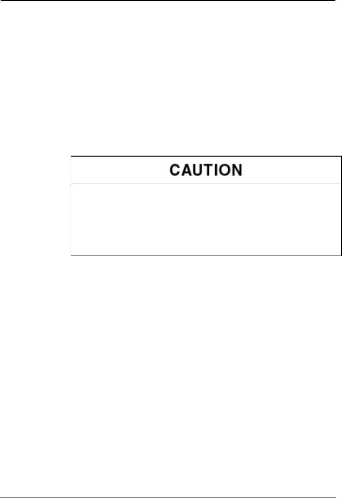
To install the hardware burden device, simply plug it into the C-Bus
network RJ-45 receptacle.
NOTE: Plug the hardware burden device only into C-Bus
receptacles.
Clipsal® RF Gateway 63249-420-273A3
Instruction Bulletin 02/2009
10 © 2009 Schneider Electric. All Rights Reserved.
Figure 3: Hardware Burden Connection on the Unit
KEY:
A. RJ-45 C-Bus receptacle on the unit
B. Hardware burden
Software Burden
The RF Gateway incorporates a software-selectable network
burden. To enable a software-selectable burden, first install a
hardware burden on the network and then enable the software
burden using C-Bus Toolkit software. After the software burden is
enabled, remove the hardware burden.
C-Bus System Clock
The RF Gateway has a software-selectable C-Bus system clock with
the capability to synchronize data communication on the C-Bus
network. Typically the clock is disabled: Successful C-Bus network
communications require only one active clock. A maximum of three
C-Bus units per network can have the clock enabled. Refer to the C-
Bus Toolkit software for additional information and to enable the RF
Gateway system clock.

63249-420-273A3 Clipsal® RF Gateway
02/2009 Instruction Bulletin
© 2009 Schneider Electric. All Rights Reserved. 11
Selecting a Location
It is important to select the right location to install the RF Gateway.
Some considerations are listed below:
Provide easy access to unit.
Locate RF Gateway where it will not be subject to water,
humidity, direct sunlight, or heavy dust.
Do not cover unit.
Only use RF Gateway indoors.
Allow adequate ventilation.
Ensure the Learn button, located on the base of the unit, can be
accessed.
The unit should be located centrally to other RF Wireless units
so that all units are within range of each other. (See Electrical
Specifications for information on the range.)
If the installation will use the infrared sensor feature, place the
unit in a location that allows the infrared receiver to be visible.
Avoid obstructions that might impede infrared signals coming
from a remote control.
CONFIGURATION AND PROGRAMMING
Before using the RF Gateway, connect it to a C-Bus wireless and
wired network. Connect to a wireless system using learn mode.
Connect to a wired network using the C-Bus Toolkit software.
Connecting to a RF Wireless Network
To link the RF Gateway to a Clipsal® RF Wireless system:
1. Press the Learn button on the base of the RF Gateway. An
indicator light at the front of the RF Gateway starts flashing
slowly. You now have 3 minutes to complete steps 2 and 3.
2. Press the Learn button on any networked wireless wall unit. The
unit's Learn LED will flash to indicate it is in learn mode.
3. Double press the Learn button on the same wall unit. This
transmits the network address to the RF Gateway. The slow
flashing indicator light on the RF Gateway will flash quickly for
about one second and then turn off to indicate that it has been
linked to the wireless system. The RF Gateway will exit Learn
mode automatically.
4. Press the Learn button on the wall unit to make the wall unit exit
Learn mode.
Clipsal® RF Gateway 63249-420-273A3
Instruction Bulletin 02/2009
12 © 2009 Schneider Electric. All Rights Reserved.
Connecting to a Wired Network
To connect the RF Gateway to a C-Bus wired network:
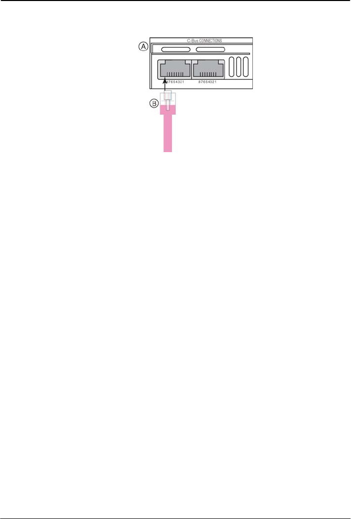
1. Remove the Wired C-Bus Connection Cover. To do so, first
uninstall the unit (if it has been mounted on the wall) and position
the base of the unit towards you. Push the cover straight up and
out.
Figure 4: Removing the C-Bus Connection Cover
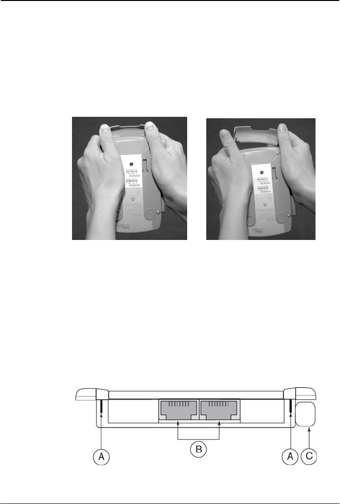
2. To connect the RF Gateway to the wired C-Bus network, plug
the C-Bus cable into either of the RJ45 sockets as described in
Wiring Guidelines and Connection to the C-Bus Network. (The
Figure shows the location of the RJ45 sockets.)
3. Use the C-Bus Toolkit software to configure the wired side of the
RF Gateway as described in Configuration.
4. Align the cover to the Gateway and snap the cover into the
mounting slots on the Gateway.
5. Position the antenna for optimal reception.
Figure 5: RF Gateway: Rear/Top View (cover removed)
KEY:
A. Wired C-Bus
cover mounting
slots
B. RJ45 sockets
C. Antenna
63249-420-273A3 Clipsal® RF Gateway
02/2009 Instruction Bulletin
© 2009 Schneider Electric. All Rights Reserved. 13
Wiring Guidelines
Follow the guidelines below when working with the RF Gateway.
Verify that the power supplying the system is turned OFF before
handling electrical power conductors.
Observe national and local electrical codes.
Isolate the RF Gateway from the Class 1 wiring. Consult your
national and local electrical codes for requirements about
isolating Class 1 wiring and Class 2 wiring terminals.
Prevent wire cuttings and debris from entering the unit.
Megger® Testing Guidelines
Do not Megger® test C-Bus data cabling or terminals. Megger
testing of data cabling or terminals can degrade the performance of
the C-Bus network.
It will not harm the units if electrical power terminals only are Megger
tested. But because units contain electronic components, the
Megger readings will not be correct. To obtain valid readings,
disconnect the power lines from the units.
HAZARD OF EQUIPMENT DAMAGE
Do not Megger® test C-Bus data cabling or terminals as it can
degrade the performance of the C-Bus network.
Failure to follow this instruction will result in damage to the C-
Bus network.
Clipsal® RF Gateway 63249-420-273A3
Instruction Bulletin 02/2009
14 © 2009 Schneider Electric. All Rights Reserved.
Connection to the C-Bus Network
The C-Bus network is connected to the Clipsal RF Wireless Control
System RF Gateway through two polarity sensitive RJ45 inputs
located on the RF Gateway. Connect the unit to the C-Bus network
with Category 5 unshielded twisted pair C-Bus network cable, and a
wired RJ45 plug. Refer to the "Wiring Connections Key Diagram"
figure, and the "RJ45 Pin Connections" table for wiring and pin
connection information.
NOTE: To clearly distinguish C-Bus from other UTP Cat5 cables, it
is recommended to use a different colored cable, or clearly label the
C-Bus UTP Cat5 cable.
NOTE: The Category 5 unshielded twisted pair C-Bus network cable
and the wired RJ45 plug are provided by the installer.
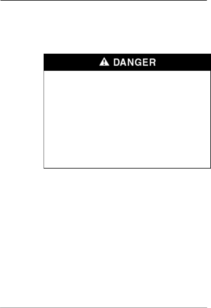
WARNING
HAZARD OF ELECTRIC SHOCK, EXPLOSION, OR ARC FLASH
Do not connect line voltage to any C-Bus terminal.
Failure to follow this instruction can result in personal injury
or equipment or property damage.
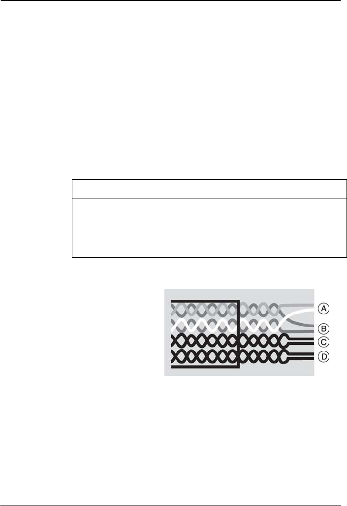
Figure 6: Wiring Connections Key Diagram
KEY:
A. C-Bus positive (+): blue + orange
B. C-Bus negative (-): blue/white + orange/white
C. Remote OFF: brown + brown/white*
D. Remote ON: green + green/white*
63249-420-273A3 Clipsal® RF Gateway
02/2009 Instruction Bulletin
© 2009 Schneider Electric. All Rights Reserved. 15
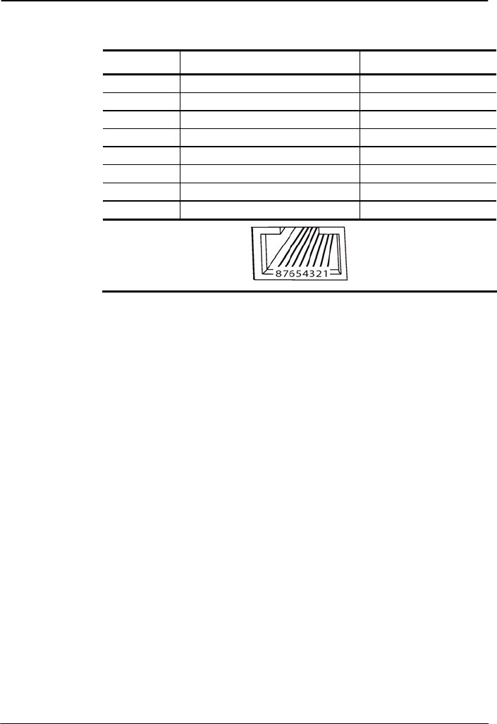
Table 2: RJ45 Pin Connections
RJ Pin C-Bus Connection Color
1 Remote ON* Green/White
2 Remote ON* Green
3 C-Bus Neg (-) Orange/White
4 C-Bus Pos (+) Blue
5 C-Bus Neg (-) Blue/White
6 C-Bus Pos (+) Orange
7 Remote OFF* Brown/White
8 Remote OFF* Brown
*Not internally connected.
Configuration
A RF Gateway consists of two separate internal sub-units, one for
the wired network and one for the wireless system. Several
gateways may be used within a wired C-Bus™ Network installation.
When the installer scans the networks using C-Bus Toolkit software
via a PC Interface, each Gateway identifies itself with one of four
names, depending on its connection type (wired or RF wireless) and
its position in the network (near or far side). See the names in the
figure "Identifying Gateways When Scanning from a PC Interface."
To configure the RF Gateway on a wired network, use C-Bus Toolkit
Software.
Clipsal® RF Gateway 63249-420-273A3
Instruction Bulletin 02/2009
16 © 2009 Schneider Electric. All Rights Reserved.
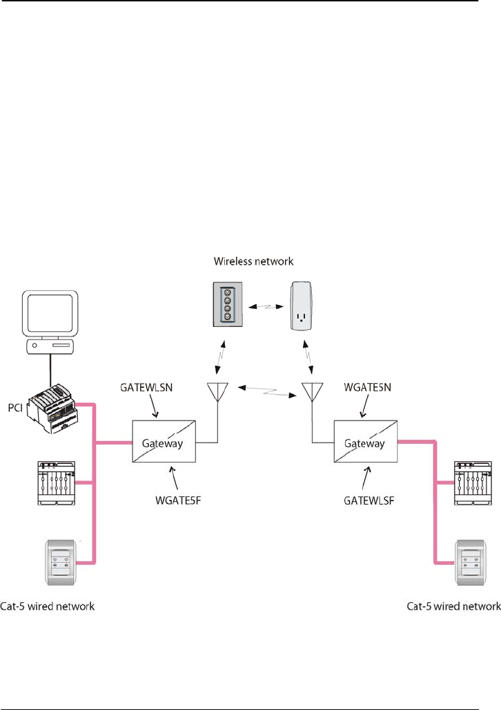
When configuring the wired side of the RF Gateway, note the
following points.
The Unit Address of the wired near side of the RF Gateway
(GATEWLSN) must match the Network Address of the
Clipsal RF wireless system being linked to.
The Unit Address of the wireless far side of the RF Gateway
(WGATE5F) must match the Network Address of the C-Bus
wired network being linked to.
The figure is a diagram of an installation with two wired networks
linked through a wireless system. The installation uses two
Gateways. Four Gateway subunits show up if the installer scans the
networks using C-Bus Toolkit software via the PC Interface (PCI).
Figure 7: Identifying Gateways When Scanning from a PCI

63249-420-273A3 Clipsal® RF Gateway
02/2009 Instruction Bulletin
© 2009 Schneider Electric. All Rights Reserved. 17
Communication Options
The RF Gateway supports explicit routing of messages into and
through both C-Bus™ wired networks and Clipsal® RF wireless
systems. Such messages are used by control software such as the
C-Bus Toolkit and control units such as the C-Touch Color Touch
Screen.
Several options are available when using the C-Bus Toolkit software
to edit the Gateway unit. The following options are included on the
"Connections" tab:
Send to adjacent network - This causes standard messages
(such as button presses) on either side of the specified "Connect
Applications" to be sent to the adjacent wired network or wireless
system. When this option is enabled, a unit with a specific Group
Address on the one side of the Gateway will be associated with
units with the same Group Address on the other side (if units
have the same Application Address).
Send to other remote network - This allows standard messages
on either side of the specified "Connect Applications" to be sent
from the wireless system to a non-adjacent C-Bus network
(possibly through one or more network bridges).
Synchronize to wired - This option applies when the Gateway is
powered up. It causes the Gateway to retrieve the levels of
groups in the wired C-Bus network, and set the levels of
corresponding groups in the wireless system to the same values.

Clipsal® RF Gateway 63249-420-273A3
Instruction Bulletin 02/2009
18 © 2009 Schneider Electric. All Rights Reserved.
Status Reporting
Wired C-Bus networks use a status reporting system (known as an
MMI). This provides automatic detection and correction of
discrepancies between the states of grouped inputs and outputs. It
also allows the C-Bus Toolkit software, and special C-Bus control
units, to take a snapshot of the states of units or groups in the
network.
RF Wireless systems use a different method of status reporting,
which is slower but better suited to a radio transmission/reception
environment. The Wireless C-Bus status reporting serves the same
purpose as the wireless C-Bus MMI.
The Gateway translates between the two status reporting types,
allowing the RF Wireless system to be scanned and browsed using
the C-Bus Toolkit software.
After powering up, the Gateway may take up to 1 minute to obtain a
complete view of the wireless system. Under some circumstances,
the Gateway can take 30 to 60 seconds to recognize that a unit has
been added to or removed from a wireless system.
When using the C-Bus Toolkit software to view units on a wireless
system, an "Update" button is provided to cause the Gateway to
rediscover all wireless units.
CARE AND CLEANING INSTRUCTIONS
Follow the precautions below to properly clean and care for the unit.
Clean regularly using a soft lint free cloth.
Only use a mild, non-abrasive cleaner such as window cleaner
lightly sprayed onto the lint free cloth to clean the unit.
Ensure hands are dry and clean before operating the unit.
Only use non-abrasive objects to operate the unit. Hard, sharp
objects may cause damage.
Leave the unit uncovered to allow adequate ventilation.
Only use the unit indoors.
Properly shade the unit so that it is not exposed to direct sunlight
for extended periods.
63249-420-273A3 Clipsal® RF Gateway
02/2009 Instruction Bulletin
© 2009 Schneider Electric. All Rights Reserved. 19
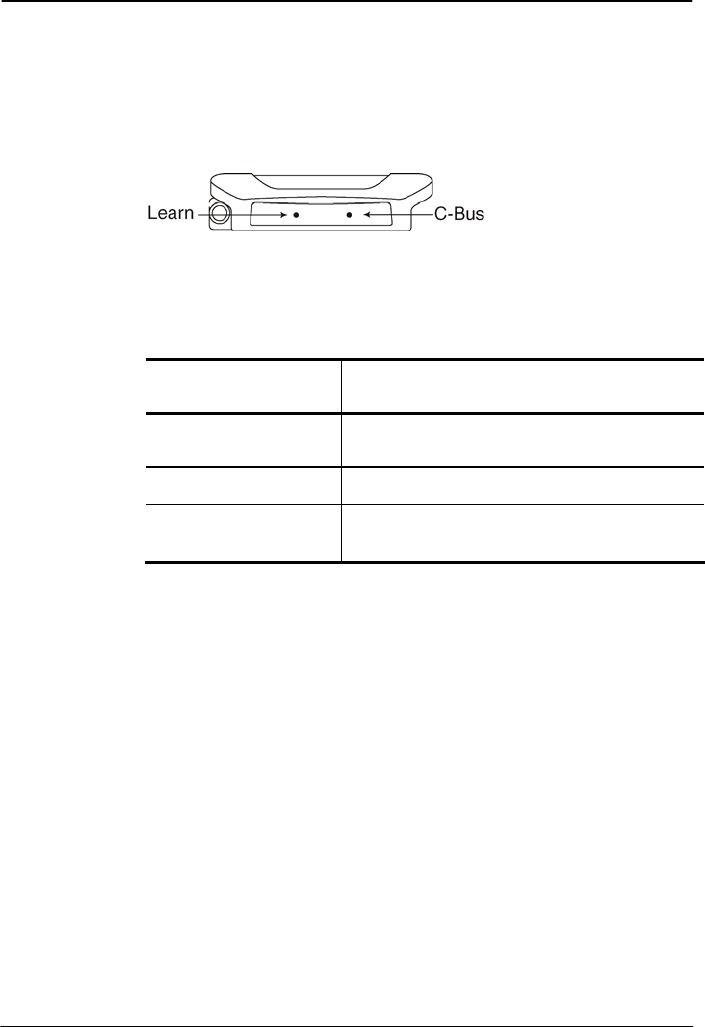
STATUS INDICATOR
The indicator lights (LED) are in the infrared sensor at the
front/bottom of the RF Gateway.
Figure 8: Location of Status Indicators
The C-Bus indicator LED shows the status of the C-Bus network at
the unit. The table explains the meaning of each type of LED
activity.
Table 3: C-Bus LED Status
C-Bus LED Activity Meaning
Off No C-Bus connection or insufficient power
Slow flashing Normal connection to C-Bus network
Quick flashing Confirms that the RF Gateway has been linked to the
RF Wireless system. Lasts about 1 second after the
link is established.
The Learn indicator LED comes on during Learn Mode.

Clipsal® RF Gateway 63249-420-273A3
Instruction Bulletin 02/2009
20 © 2009 Schneider Electric. All Rights Reserved.
ELECTRICAL SPECIFICATIONS
Table 4: Specifications
Parameter Description
C-Bus supply voltage 15 to 36 V DC, 32 mA
RF frequency 916 MHz
Transmitting power 5 mW
Typical range (range depends
on building construction and
the proximity to dense or
metallic objects)
Timber frame / brick veneer construction
49.2 to 65.6 feet (15 to 20 m)
Brick, stone, or steel frame construction
32.8 to 49.2 feet (10 to 15 m)
Steel reinforced concrete construction
16.4 to 32.8 feet (5 to 10 m)
Maximum range (open air) 196.8 feet (60 m)
Operating temperature range 32 to 104 °F (0 to 40 °C)
Operating humidity range 10 to 95% RH (non-condensing)
63249-420-273A3 Clipsal® RF Gateway
02/2009 Instruction Bulletin
© 2009 Schneider Electric. All Rights Reserved. 21
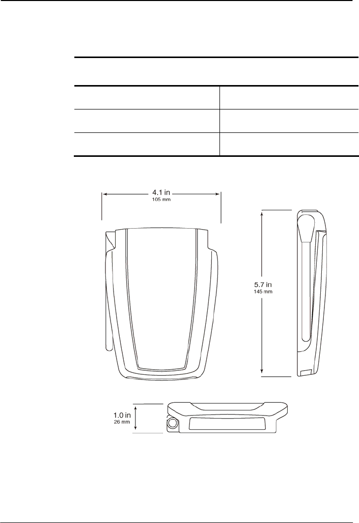
DIMENSIONS
Table 5: RF Gateway Dimensions
Parameter Description
Dimensions (W x H x D) 4.1 x 5.9 x 1.0 inches
(105 x 149 x 26 mm)
Weight 3.7 ounces
(105 g)
Mounting centers 1.6 inches
(40 mm)
Clipsal® RF Gateway 63249-420-273A3
Instruction Bulletin 02/2009
22 © 2009 Schneider Electric. All Rights Reserved.
STANDARDS
The RF Gateway complies with the following Standards:
Table 6: U.S. and Canadian Product Safety Standards and U.S.
FCC Regulations
Standards/Regulations Title
CSA C22.2 No. 205 Signal Equipment
UL916 Energy Management Equipment
FCC Part 15 Class B Digital Device for Home or Office Use

Clipsal® RF Gateway
Instruction Bulletin
Schneider Electric, USA
320 Tech Park Drive, Suite 100
La Vergne, TN, 37086
1-888-SquareD (1-888-778-2733)
www.squaredlightingcontrol.com
Square D, , Clipsal, C-Bus, Saturn and Neo are trademarks or
registered trademarks of Schneider Electric and/or its affiliates in the
United States and/or other countries.
Electrical equipment should be installed, operated, serviced, and
maintained only by qualified personnel. No responsibility is assumed by
Schneider Electric for any consequences arising out of the use of this
material.
© 2008 Schneider Electric. All Rights Reserved.
63249-420-273A3 02/2009
SUPPORT AND SERVICE
Contact the Square D Customer Information Center for technical
support by phone at 1-888-Square D (1-888-778-2733) or e-mail at
lightingcontrol.support@us.schneider-electric.com.
Contact your local Square D service representative or Clipsal®
certified installer for repairs or service to your network.
You may also find helpful information on our web site at
www.squaredlightingcontrol.com.