Schneider Electric Processor Adapter Users Manual
Processor Adapter to the manual 5751cc3c-15ee-4980-8419-35c0688355e4
2015-02-06
: Schneider-Electric Schneider-Electric-Processor-Adapter-Users-Manual-526946 schneider-electric-processor-adapter-users-manual-526946 schneider-electric pdf
Open the PDF directly: View PDF ![]() .
.
Page Count: 425 [warning: Documents this large are best viewed by clicking the View PDF Link!]

Momentum
M1 Processor Adapter and
Option Adapter User Guide
870 USE 101 10 Version 2
Data, Illustrations, Alterations
Data and illustrations are not binding. We reserve the right to alter products in line with our policy of continuous product development.
If you have any suggestions for improvements or amendments or have found errors in this publication, please notify us by e-mail at
techcomm@modicon.com.
Training
Schneider Electric Inc. offers suitable further training on the system.
Hotline
See addresses for Technical Support Centers at the end of this publication.
Trademarks
All terms used in this publication to denote Schneider Electric Inc. products are trademarks of Schneider Electric Inc.
All other terms used in this publication to denote products may be registered trademarks and/or trademarks of the corresponding
corporations.
Copyright
All rights are reserved. No part of this document may be reproduced or transmitted in any form or by any means, electronic or
mechanical, including copying, processing or by online file transfer, without permission in writing from Schneider Electric Inc. You are
not authorized to translate this document into any other language.
© 2000 Schneider Electric Inc. All rights reserved.

November 2000
Momentum
M1 Processor Adapter and
Option Adapter User Guide
870 USE 101 10 Version 2.0

Document Set
Momentum I/O Bases User Guide
870 USE 002 00
Momentum Interbus Communication Adapter User Manual
870 USE 003 00
Momentum FIPIO Communication Adapter User Manual
870 USE 005 00
Momentum Ethernet Communciation Adapter User Guide
870 use 112 00
170 PNT Series Modbus Plus Communication Adapters for Momentum
User Guide
870 USE 103 00
170 NEF Series Modbus Plus Communication Adapters for Momentum
User Guide
870 USE 111 00

Preface
870 USE 101 10 V.2 v
Preface The data and illustrations found in this book are not binding. We reserve the right
to modify our products in line with our policy of continuous product development.
The information in this document is subject to change without notice and should
not be construed as a commitment by Schneider Electric, Inc.
Schneider Electric, Inc assumes no responsibility for any errors that may appear in
this document. If you have any suggestions for improvements or amendments or
have found errors in this publication, please notify us through your distributor or
local Square D office.
No part of this document may be reproduced in any form or by any means,
electronic or mechanical, including photocopying, without express written
permission of the Publisher, Schneider Electric, Inc.
MODSOFT® is a registered trademark of Schneider Electric, Inc.
The following are trademarks of Schneider Electric, Inc.:
Modbus Modbus Plus Concept
Modicon 984
DIGITAL® and DEC® are registered trademarks of Digital Equipment
Corporation.
IBM® and IBM AT® are registered trademarks of International Business
Machines Corporation.
Microsoft® and MS-DOS® are registered trademarks of Microsoft Corporation.
©Copyright 2000, Schneider Electric, Inc.
Printed in U.S.A.
CAUTION
All pertinent state, regional, and local safety regulations must be observed when
installing and using this product.
For reasons of safety and to assure compliance with documented system data, repairs to
components should be performed only by the manufacturer.
Failure to observe this precaution can result in injury or equipment damage.

Preface
vi 870 USE 101 10 V.2

870 USE 101 10 V.2 vii
Contents
About This Book ..........................................................................................15
Revision History..............................................................................................15
Document Scope............................................................................................16
Validity Note ...................................................................................................16
Related Documentation..................................................................................16
User Comments..............................................................................................16
Part I Getting Started........................................................................17
Chapter 1 Overview of Momentum M1 Processor Adapters ...............19
Section 1.1 Introducing the M1 Processor Adapters ........................................................20
Overview ........................................................................................................20
Front Panel illustration ...................................................................................21
Overview of Ports ..........................................................................................22
Memory and Performance Characteristics ....................................................24
Power Supply ................................................................................................27
Section 1.2 Features of Each Processor Adapter ............................................................28
Overview ........................................................................................................28
171 CCS 700 00 ............................................................................................29
171 CCS 700 10 ............................................................................................32
171 CCS 760 00 ............................................................................................35
171 CCC 760 10 ............................................................................................38
171 CCS 780 00 ............................................................................................41
171 CCC 780 10 ............................................................................................44
171 CCC 960 20 ............................................................................................47
171 CCC 960 30 ............................................................................................51
171 CCC 980 20 ............................................................................................56
171 CCC 980 30 ............................................................................................60

Contents
viii 870 USE 101 10 V.2
Chapter 2 Overview of Momentum Option Adapters ...........................65
Section 2.1 Introducing the Momentum Option Adapters .................................................66
Basic Features of Option Adapters ...............................................................66
Section 2.2 Serial Option Adapter ....................................................................................67
Overview .......................................................................................................67
Front Panel Components ..............................................................................68
Specifications ................................................................................................71
Section 2.3 Modbus Plus Option Adapter ........................................................................73
Overview .......................................................................................................73
Front Panel Components ..............................................................................74
Specifications ................................................................................................77
Section 2.4 Redundant Modbus Plus Option Adapter ......................................................79
Overview .......................................................................................................79
Front Panel Components ..............................................................................80
Specifications ................................................................................................84
Chapter 3 Assembling Momentum Components .................................87
Section 3.1 Assembling a CPU ........................................................................................88
Overview .......................................................................................................88
Assembling a Processor Adapter and I/O Base ............................................89
Disassembling a Processor Adapter from an I/O Base .................................92
Section 3.2 Assembling a CPU with an Option Adapter ...................................................94
Overview .......................................................................................................94
Assembling a Processor Adapter and an Option Adapter .............................95
Mounting the Assembled Adapters on the I/O Base .....................................98
Disassembling a Module with an Option Adapter ..........................................101
Section 3.3 Installing Batteries in an Option Adapter .......................................................105
Installation Guidelines ...................................................................................105
Section 3.4 Labeling the CPU ..........................................................................................107
Guidelines for Labeling the CPU ...................................................................107
Part II Communication Ports ...........................................................109
Chapter 4 Using the Modbus Ports .......................................................111
Section 4.1 Modbus Port 1 ...............................................................................................112
Overview .......................................................................................................112
Modbus Port 1 ...............................................................................................113
Cable Accessories for Modbus Port 1 ...........................................................116

Contents
870 USE 101 10 V.2 ix
Pinouts for Modbus Port 1 .............................................................................117
Section 4.2 Modbus Port 2 ...............................................................................................119
Overview ........................................................................................................119
Modbus Port 2 ...............................................................................................120
Four-Wire Cabling Schemes for Modbus RS485 Networks ..........................123
Two-Wire Cabling Schemes for Modbus RS485 Networks ...........................126
Cable for Modbus RS485 Networks .............................................................129
Connectors for Modbus RS485 Networks .....................................................132
Terminating Devices for Modbus RS485 Networks .......................................134
Pinouts for Modbus RS485 Networks ............................................................135
Chapter 5 Using the Ethernet Port ........................................................141
Section 5.1 Ethernet Port .................................................................................................142
Ethernet Port .................................................................................................143
Network Design Considerations ....................................................................144
Security ..........................................................................................................146
Cabling Schemes ..........................................................................................147
Pinouts ...........................................................................................................148
Assigning Ethernet Address Parameters .......................................................149
Using BOOTP Lite to Assign Address Parameters .......................................152
Reading Ethernet Network Statistics .............................................................153
Description .....................................................................................................154
Section 5.2 Establishing a Connection with an Ethernet Module .....................................158
Establishing a Connection with an Ethernet Module .....................................159
Section 5.3 Accessing Embedded Web Pages ................................................................162
Accessing the Web Utility Home Page ..........................................................163
Section 5.4 171 CCC 960 30 AND 171 CCC 980 30 Web Pages ....................................164
Momentum M1E Web Pages .........................................................................165
Momentum M1E Indicators ............................................................................170
Chapter 6 Using the I/OBus Port ...........................................................171
I/O Bus Port ...................................................................................................172
How I/OBus Works ........................................................................................173
Network Status Indication in the M1 Ethernet Module ...................................174
Guidelines for I/OBus Networks ....................................................................175
Cable Accessories .........................................................................................177
Pinouts ...........................................................................................................179
Chapter 7 Using the Modbus Plus Ports ...............................................181
Modbus Plus Features for Momentum ..........................................................182
Two Types of Modbus Plus Networks ...........................................................183
Standard Cabling Schemes ...........................................................................185
Cluster Mode Cabling Schemes ....................................................................187

Contents
x870 USE 101 10 V.2
Cable Accessories for Modbus Plus Networks ..............................................191
Pinouts and Wiring Illustrations for Modbus Plus Networks ..........................194
Modbus Plus Addresses ................................................................................198
Peer Cop .......................................................................................................200
Part III Modsoft ...................................................................................203
Chapter 8 Configuring an M1 CPU with Modsoft .................................205
Section 8.1 Configuring the Processor Adapter ...............................................................206
Overview .......................................................................................................206
Selecting an M1 Processor Adapter ..............................................................207
Specifying an M1 Processor Type .................................................................210
Default Configuration Parameters .................................................................212
Changing the Range of Discrete and Register References ..........................215
Changing the Size of Your Application Logic Space .....................................217
Changing the Number of Segments ..............................................................218
Changing the Size of the I/O Map .................................................................220
Establishing Configuration Extension Memory ..............................................222
Section 8.2 Configuring Option Adapter Features ............................................................223
Overview .......................................................................................................223
Reserving and Monitoring a Battery Coil .......................................................224
Setting up the Time-of-Day Clock .................................................................226
Setting the Time ............................................................................................228
Reading the Time-of-Day Clock ....................................................................231
Section 8.3 Modifying Communication Port Parameters ..................................................232
Overview .......................................................................................................232
Accessing the Port Editor Screen ..................................................................233
Parameters Which Should Not Be Changed .................................................234
Changing the Mode and Data Bits ................................................................235
Changing Parity .............................................................................................237
Changing the Baud Rate ...............................................................................238
Changing the Modbus Address .....................................................................239
Changing the Delay .......................................................................................240
Changing the Protocol on Modbus Port 2 .....................................................241
Section 8.4 I/O Mapping the Local I/O Points ..................................................................242
Accessing and Editing the I/O Map ...............................................................242
Chapter 9 I/O Mapping an I/OBus Network with Modsoft ....................247
Supporting an I/O Map for an I/OBus Network ..............................................248
Accessing an I/O Map Screen for an I/OBus Network ..................................250
Editing the I/OBus I/O Map ............................................................................252

Contents
870 USE 101 10 V.2 xi
Chapter 10 Configuring a Modbus Plus Network in Modsoft
with Peer Cop .........................................................................257
Section 10.1 Getting Started ..............................................................................................258
Overview ........................................................................................................258
Accessing the Peer Cop Configuration Extension Screen ............................259
The Default Peer Cop Screen .......................................................................261
Section 10.2 Using Modbus Plus to Handle I/O .................................................................263
Overview ........................................................................................................263
Devices on the Network .................................................................................264
Defining the Link and Accessing a Node .......................................................265
Confirming the Peer Cop Summary Information ............................................268
Specifying References for Input Data ............................................................272
Accessing the Remaining Devices ................................................................276
Completing the I/O Device Configuration in Peer Cop ..................................278
Section 10.3 Passing Supervisory Data over Modbus Plus ...............................................281
Overview ........................................................................................................281
Devices on the Network .................................................................................282
Configuring a Node to Exchange Data ..........................................................283
Confirming the Peer Cop Summary Information ............................................286
Specifying References for Input and Output Data .........................................287
Defining the References for the Next Node ...................................................292
Defining References for the Supervisory Computer ......................................297
Completing the Configuration ........................................................................302
Chapter 11 Saving to Flash in Modsoft ...................................................303
Preparing to Save to Flash ............................................................................304
Saving to Flash ..............................................................................................305
Part IV Concept ..................................................................................307
Chapter 12 Configuring an M1 CPU with Concept .................................309
Section 12.1 Configuring the Processor Adapter ...............................................................310
Overview ........................................................................................................310
Selecting an M1 Processor Adapter ..............................................................311
Default Configuration Parameters .................................................................315
Changing the Range of Discrete and Register References ...........................318
Changing the Size of the Full Logic Area ......................................................320
Understanding the Number of Segments ......................................................321
Changing the Size of the I/O Map .................................................................322
Establishing Configuration Extension Memory for Peer Cop .........................324
Section 12.2 Configuring Option Adapter Features ............................................................327

Contents
xii 870 USE 101 10 V.2
Overview .......................................................................................................327
Reserving and Monitoring a Battery Coil .......................................................328
Setting up the Time-of-Day Clock .................................................................331
Setting the Time ............................................................................................334
Reading the Time-of-Day Clock ....................................................................335
Section 12.3 Modifying Modbus Port Parameters ..............................................................336
Overview .......................................................................................................336
Accessing the Modbus Port Settings Dialog Box ..........................................337
Changing the Baud Rate ...............................................................................338
Changing Mode and Data Bits ......................................................................339
Stop Bit Should Not Be Changed ..................................................................340
Changing Parity .............................................................................................340
Changing the Delay .......................................................................................341
Changing the Modbus Address .....................................................................342
Changing the Protocol on Modbus Port 2 .....................................................343
Section 12.4 Configuring Ethernet Address Parameters and I/O Scanning .......................344
Overview .......................................................................................................344
Accessing the Ethernet / I/O Scanner Screen ...............................................345
Ethernet Configuration Options .....................................................................347
Setting Ethernet Address Parameters ...........................................................348
Configuring I/O ..............................................................................................350
Completing the I/O Configuration ..................................................................354
Section 12.5 I/O Mapping the Local I/O Points ..................................................................357
Accessing and Editing the I/O Map ...............................................................357
Chapter 13 I/O Mapping an I/OBus Network with Concept ...................361
Supporting an I/O Map for an I/OBus Network ..............................................362
Accessing an I/O Map Screen for an I/OBus Network ..................................363
Editing the I/OBus I/O Map ............................................................................365
Chapter 14 Configuring a Modbus Plus Network in Concept
with Peer Cop .........................................................................369
Section 14.1 Getting Started ..............................................................................................370
Overview .......................................................................................................370
Accessing the Peer Cop Dialog Box .............................................................371
Adjusting the Amount of Extension Memory .................................................373
Other Default Settings in the Peer Cop Dialog Box .......................................374
Section 14.2 Using Modbus Plus to Handle I/O .................................................................376
Overview .......................................................................................................376
Devices on the Network ................................................................................377
Changing the Peer Cop Summary Information .............................................378
Specifying References for Input Data ............................................................380

Contents
870 USE 101 10 V.2 xiii
Specifying References for Output Data .........................................................384
Section 14.3 Passing Supervisory Data over Modbus Plus ...............................................387
Overview ........................................................................................................387
Devices on the Network .................................................................................388
Specifying References for Input and Output Data .........................................389
Defining the References for the Next Node ...................................................393
Defining References for the Supervisory PLC ...............................................396
Chapter 15 Saving to Flash with Concept ..............................................399
Saving to Flash ..............................................................................................399
Part V Appendices .............................................................................403
Appendix A Ladder Logic Elements and Instructions ............................405
Standard Ladder Logic Elements ..................................................................406
DX Loadable Support ....................................................................................410
A Special STAT Instruction ............................................................................411
Appendix B Run LED Flash Patterns and Error Codes ...........................417
Index ............................................................................................................421

Contents
xiv 870 USE 101 10 V.2

870 USE 101 10 V.2 15
About This Book
Revision History This is version 2.0 of this manual, 870 USE 101 1
x
, which replaces 870 USE 101 0
x
.
The following information has been added or changed:
The most recent version of this manual is available on our web site,
www.modicon.com.
Version Change
1.0 Never released.
2.0 Addition of new Ethernet-capable processors.

About This Book
16 870 USE 101 10 V.2
About Book
Document Scope This manual contains complete information about the Momentum M1 Processor
Adapters, Option Adapters and Ethernet Adapters. It does not contain information
about Momentum I/O bases or Communication Adapters.
Validity Note This manual is valid for Modsoft 2.6.1 and Concept 2.2.
Related
Documentation You may find the following other manuals useful:
User Comments We welcome your comments about this document. You can reach us by e-mail at
techcomm@modicon.com.
Title Part Number
Momentum I/O Bases User Guide 870 USE 002 00
Momentum Modbus Plus PNT Series Communication
Adapters User Guide
870 USE 103 00
Momentum Modbus Plus NEF Series Communication
Adapters User Guide
870 USE 111 00
Quantum NOE 771 x0 Ethernet Modules User Guide 840 USE 116 00
FactoryCast User’s Guide For Quantum and Premium 890 USE 152 00
Momentum Interbus Communication Adapter User
Manual
870 USE 003 00
Momentum Ethernet Communication Adapter User
Guide
870 USE 112 00

870 USE 101 10 V.2 17
Getting Started
At a Glance
Purpose This part describes the M1 Processor Adapters and Option Adapters and explains
how to assemble them.
In This Part This part contains the following chapters:
For Information On... See Chapter... On Page...
Overview of Momentum M1 Processor Adapters 1 19
Overview of Momentum Option Adapters 2 65
Assembling Momentum Components 3 87

Getting Started
18 870 USE 101 10 V.2

870 USE 101 10 V.2 19
Overview of Momentum M1
Processor Adapters
At a Glance
Purpose A Momentum M1 Processor Adapter can be snapped onto a Momentum I/O base
to create a central processing unit (CPU) that provides programmable logic control
to local and distributed I/O.
This chapter describes the M1 Processor Adapters.
In This Chapter This chapter contains the following sections:
For This Topic... See Section... On Page...
Introducing the M1 Processor Adapters 1 20
Features of Each Processor Adapter 2 28

Overview of Momentum M1 Processor Adapters
20 870 USE 101 10 V.2
Section 1.1
Introducing the M1 Processor Adapters
Overview
Purpose A Momentum M1 Processor Adapter stores and executes the application program,
controlling the local I/O points of its host I/O base and distributed I/O devices on a
common communication bus.
This section describes the front panel components, memory and performance
characteristics of M1 Processor Adapters.
In This Section This section contains the following topics:
For This Topic... See Page...
Front Panel illustration 21
Overview of Ports 22
Memory and Performance Characteristics 24
Power Supply 27
Overview of Momentum M1 Processor Adapters
870 USE 101 10 V.2 21
Front Panel illustration
Introduction This section provides an illustration of a typical M1 Processor Adapter.
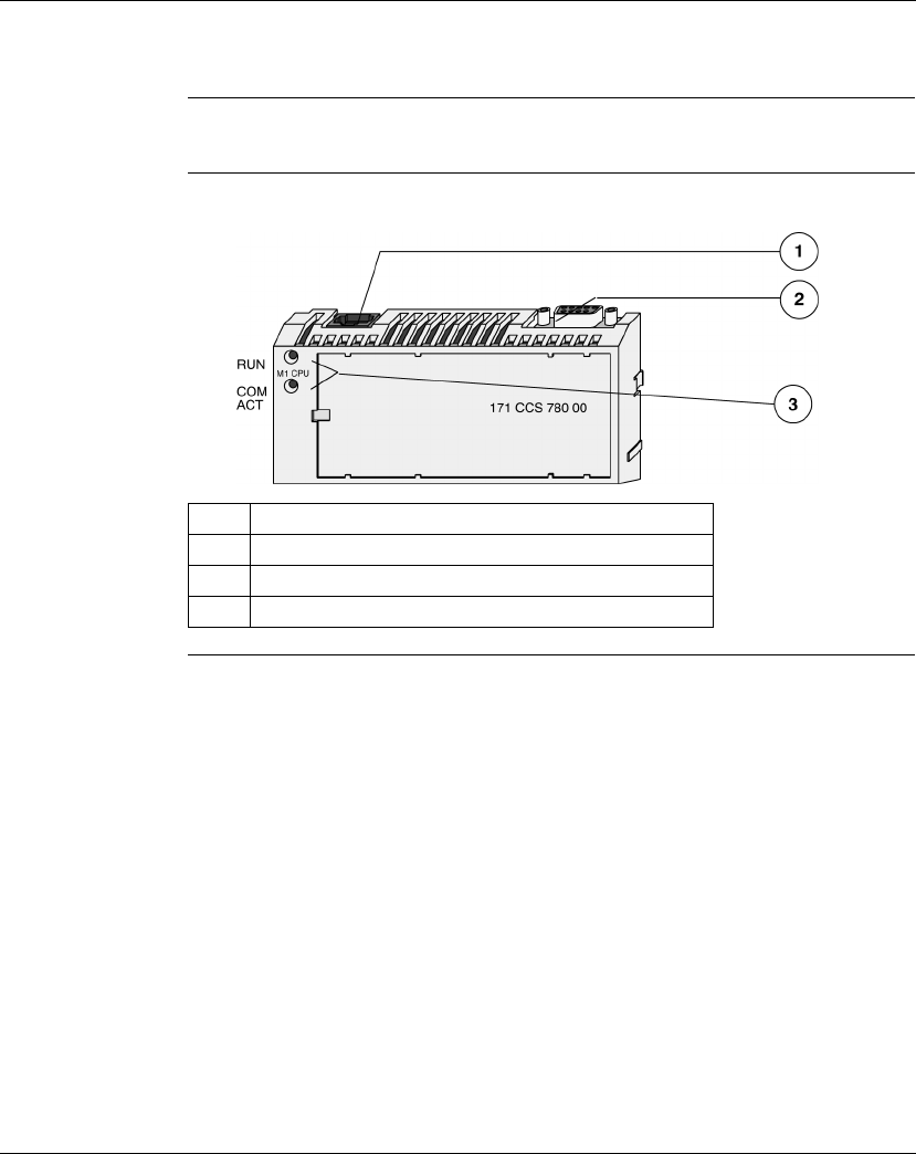
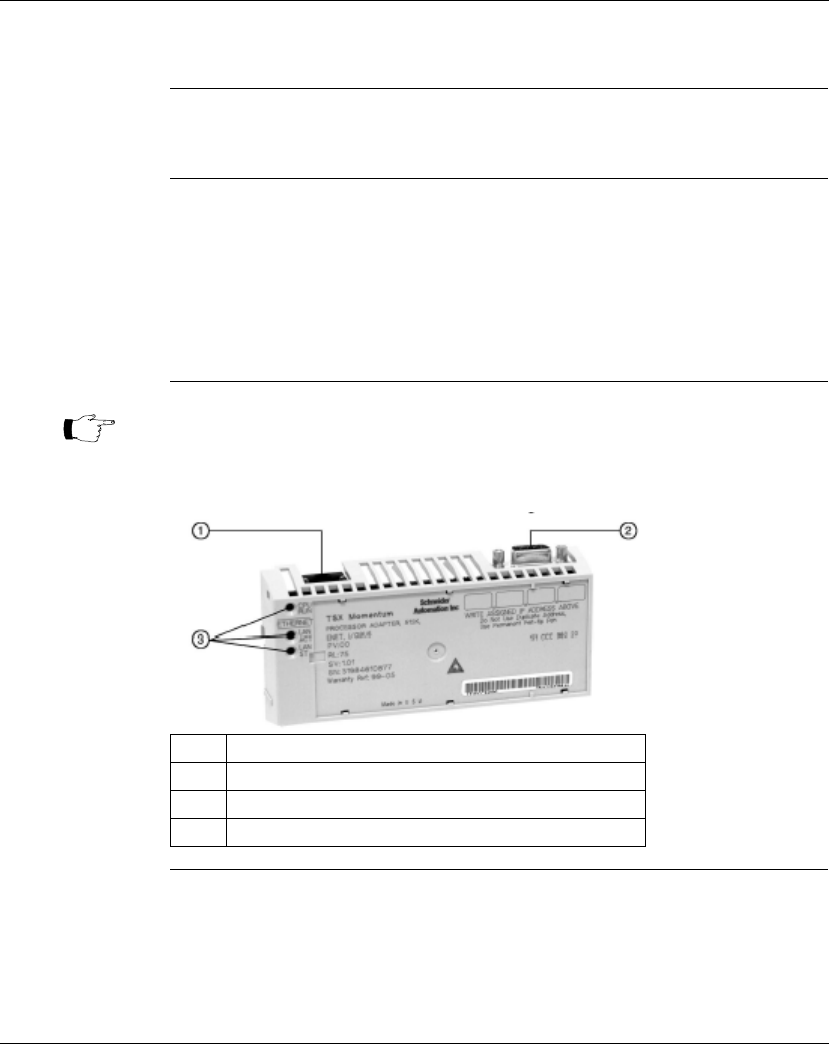
Illustration A typical Processor Adapter is shown in the following illustration:
Label Description
1 Standard port connector
2 Optional second port connector
3 LED indicators
Overview of Momentum M1 Processor Adapters
22 870 USE 101 10 V.2
Overview of Ports
Introduction Each Processor Adapter is equipped with at least one Modbus or Ethernet port.
Some models also have a second port. The ports allow the Processor Adapter to
communicate with:
lProgramming panels
lNetwork I/O points under its control
lNetwork supervisory computers
Ports Per
Processor
Adapter
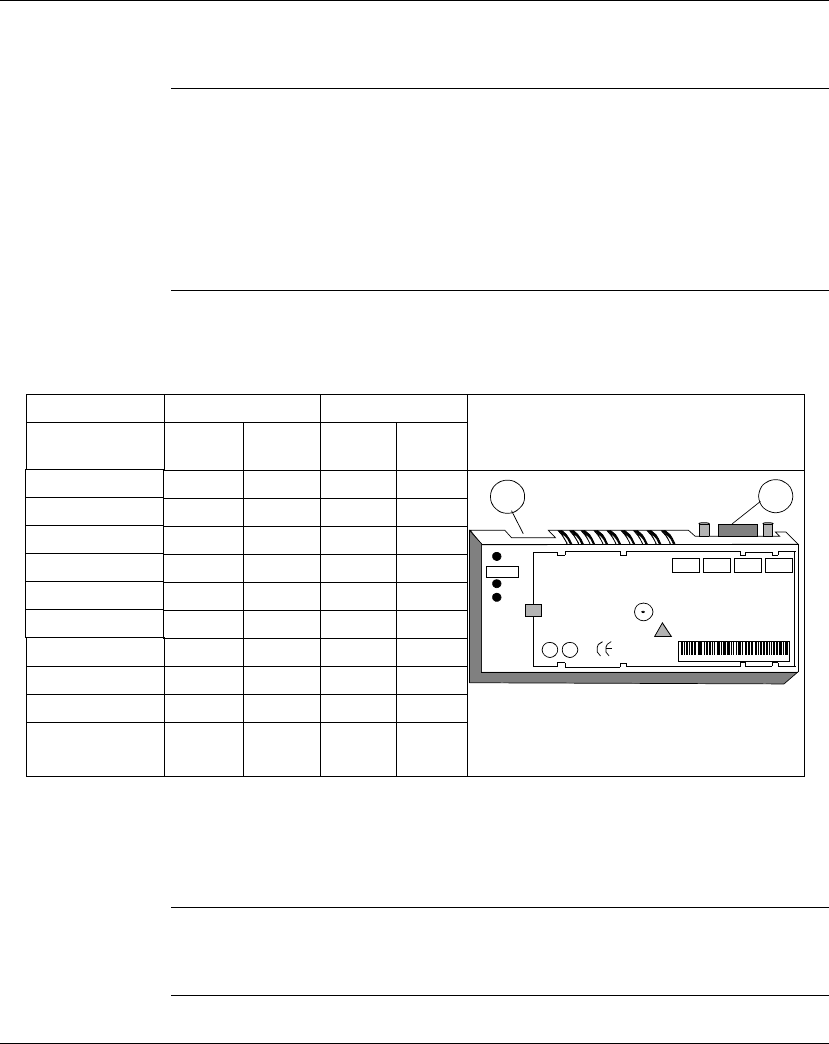
The following table indicates which ports are available with each Processor
Adapter:
Ethernet Port The Ethernet port is a standard, twisted pair, Ethernet 10BASE-T port which can
communicate with programming panels, other M1 Processor Adapters with
Ethernet ports, and with other Ethernet products. This port has an RJ45 connector,
with an industry standard pinout.
Modbus Port 1 Modbus Port 1 is a general-purpose asynchronous serial port with dedicated
RS232 slave functionality. This port has an RJ45 connector.
Continued on next page
Port 1 Port 2
Processor
Adapter Ethernet
Port Modbus
RS-232 Modbus
RS-485 I/O Bus
Port
171 CCS 700 00 x
171 CCS 700 10 x
171 CCS 760 00 x x
171 CCC 760 10 x x
171 CCS 780 00 x x
171 CCC 780 10 x x
171 CCC 960 20 x x
171 CCC 960 30 x x
171 CCC 980 20 x x
171 CCC 980 30 x x 1.
2
1
171 CCS 780 00
Schneider
Automation Inc.
2.
Port 1
Port 2

Overview of Momentum M1 Processor Adapters
870 USE 101 10 V.2 23
Overview of Ports, Continued
Modbus Port 2 Modbus Port 2 is a general-purpose asynchronous serial port with dedicated
RS485 slave functionality. This port has a 9-pin D connector.
I/OBus Port The I/OBus port is used to control and communicate with other network (non-local)
I/O modules under the control of the CPU. This port has a 9-pin D connector.

Overview of Momentum M1 Processor Adapters
24 870 USE 101 10 V.2
Memory and Performance Characteristics
Introduction Processor Adapters are equipped with internal memory and Flash RAM. This
section explains those two types of memory and describes the memory size and
performance characteristics of each Processor Adapter.
Internal Memory Internal memory includes user memory and state RAM:
lUser memory contains the control logic program and such system overhead as
the Processor Adapter configuration, I/O mapping, checksum and system
diagnostics.
lState RAM is the area in memory where all the input and output references for
program and control operations are defined and returned.
The user may change the way internal memory is allocated by adjusting
parameters for user memory and state RAM.
Flash RAM Flash RAM contains the executive firmware, which is the operating system for the
PLC. It also contains a firmware kernel, which cannot be changed. The kernel is a
small portion of memory that recognizes acceptable executive firmware packages
and allows them to be downloaded to the Processor Adapter.
Space is also provided in Flash so that a copy of the user program and state RAM
values can be stored. This back-up capability is particularly useful in configurations
where no battery is used (i.e., a Processor Adapter without an Option Adapter).
When the module is successfully communicating with other devices, if a ring
adapter with battery back up is not present, it is recommended that you stop the
processor and save the user program to Flash. This will save the processor’s ARP
cache and enable it to “remember” this information if power is lost or removed.
This procedure should also be followed whenever:
lA new or substitute device is installed on the network;
lThe IP address of a network device has been changed.
Continued on next page
Note: Some processors run both IEC and Ladder Logic and some run only IEC.
See table following.

Overview of Momentum M1 Processor Adapters
870 USE 101 10 V.2 25
Memory and Performance Characteristics, Continued
Memory Size and
Clock Speed The memory size and clock speed of each processor are described in the table
below:
Processor 984LL Flash RAM Clock Speed 984LL
Program
Memory
IEC
Program
Memory
171 CCS 700 00 64K bytes 256K bytes 20MHz 2.4k -
171 CCS 700 10 64K bytes 256K bytes 32MHz 2.4k -
171 CCS 760 00 256K bytes 256K bytes 20MHz 12k 160k
171 CCC 760 10 512K bytes 512K bytes 32MHz 18k 240k
171 CCS 780 00 64K bytes 256K bytes 20MHz 2.4k -
171 CCC 780 10 512K bytes 512K bytes 32MHz 18k 240k
171 CCC 960 20 544K bytes 512K bytes 50 MHz 18k -
171 CCC 960 30 544K bytes 1 megabyte 50 MHz 18k 200k
171 CCC 980 20 544K bytes 512K bytes 50 MHz 18k -
171 CCC 980 30 544K bytes 1 megabyte 50 MHz 18k 200k
* In a default configuration. The amount of user memory may be increased or decreased by
adjusting other parameters.

Overview of Momentum M1 Processor Adapters
26 870 USE 101 10 V.2
Memory and Performance Characteristics, Continued
Input and Output
References The number of registers (for 3
x
and 4
x
references) and discretes (for 0
x
and 1
x
references) supported by each processor are described in the table below:
Processor Adapter 984LL Executive IEC Executive
Registers Discretes Registers Discretes
171 CCS 700 00 2048 2048*
171 CCS 700 10 2048 2048*
171 CCS 760 00 4096 2048* 4096 2048 0
x
references
2048 1
x
references
171 CCC 760 10 26048 8192 0
x
references
8192 1
x
references
26048 8192 0
x
references
8192 1
x
references
171 CCS 780 00 2048 2048*
171 CCC 780 10 26048 8192 0
x
references
8192 1
x
references
26048 8192 0
x
references
8192 1
x
references
171 CCC 960 20 26048 8192 0
x
references
8192 1
x
references
171 CCC 960 30 26048 8192 0
x
references
8192 1
x
references
11,200 4096 0
x
references
4096 1
x
references
171 CCC 980 20 26048 8192 0
x
references
8192 1
x
references
171 CCC 980 30 26048 8192 0
x
references
8192 1
x
references
11,200 4096 0
x
references
4096 1
x
references
*This total may include any combination of 0
x
and 1
x
references.

Overview of Momentum M1 Processor Adapters
870 USE 101 10 V.2 27
Power Supply
Supplied by
Base A Processor Adapter requires 5 V, which is supplied by its I/O base.
Note: For information about the 171 CPS 111 00 TIO Power Supply Module,
refer to 870 Use 002 00 V. 2
Momentum I/O Base User Guide

Overview of Momentum M1 Processor Adapters
28 870 USE 101 10 V.2
Section 1.2
Features of Each Processor Adapter
Overview
Purpose This section provides a photograph, description of key features and LEDs, and
specifications for each Processor Adapter.
In This Section This section contains the following topics.
For This Topic... See Page...
171 CCS 700 00 29
171 CCS 700 10 32
171 CCS 760 00 35
171 CCC 760 10 38
171 CCS 780 00 41
171 CCC 780 10 44
171 CCC 960 20 47
171 CCC 960 30 51
171 CCC 980 20 56
171 CCC 980 30 60
Overview of Momentum M1 Processor Adapters
870 USE 101 10 V.2 29
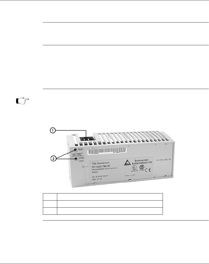
171 CCS 700 00
Overview This section describes the 171 CCS 700 00 Processor Adapter, including key
features, an illustration and specifications.
Key Features The key features of this Processor Adapter are:
lModbus Port 1
l64K bytes of internal memory
l20 MHz clock speed
Illustration The connector and LED indicators are shown in the following illustration:
Continued on next page
Note: The Modbus port connector looks like a Ethernet port connector. Do not
attempt to use an Modbus adapter as an Ethernet unit. Do not attempt to
place an Ethernet connector in a Modbus connector.
Label Description
1 Modbus Port 1 connector
2 LED indicators

Overview of Momentum M1 Processor Adapters
30 870 USE 101 10 V.2
171 CCS 700 00, Continued
LED Indicators This Processor Adapter has two LED indicators, RUN and COM ACT. Their
functions are described in the table below:
Specifications The following table contains specifications for the 171 CCS 700 00 Momentum M1
Processor Adapter:
Continued on next page
LED Status Function
Start up Both Single flash. Indicates good health.
RUN Green On continuously when the CPU has received power and is
solving logic.
Flashes an error pattern if the CPU is in kernel mode.
(See
Run LED Flash Patterns and Error Codes
on page 417)
Off CPU is not powered up or is not solving logic.
COM ACT Green May be on continuously or blinking. Indicates activity on
Modbus port 1.
Off No activity on Modbus port 1.
Memory
Internal Memory 64K bytes
User Memory 2.4K words
Flash RAM 256K bytes
Clock Speed 20 MHz
Input and Output References
Registers 2048
Discretes 2048 (any combination of 0
x
and 1
x
references)
I/O Servicing
Local I/O Services all the points on any host Momentum I/O base
Watchdog timeout 419 ms
Logic solve time 0.25 ms/k ladder logic instructions

Overview of Momentum M1 Processor Adapters
870 USE 101 10 V.2 31
171 CCS 700 00, Continued
Specifications,
Continued Mechanical
Weight 42.5 g (1.5 oz.)
Dimensions (HxDxW) 25.9x61.02x125mm
(1.01 x 2.37 x 4.86 in)
Material (Enclosures/
bezels)
Lexan
Operating Conditions
Temperature 0 ... 60 degrees C
Humidity 5 ... 95% (noncondensing)
Chemical interactions Enclosures and bezels are made of Lexan,
a polycarbonate that can be damaged by strong
alkaline solutions
Altitude, full operation 2000m (6500ft)
Vibration 10 ... 57Hz @ 0.075mm displacement amplitude
57...150Hz @ 1g
Ref. IEC 68-2-6 FC
Shock +/-15g peak, 11ms, half sine wave
Ref. IEC 68-2-27 EA
RFI Susceptibility/
immunity
Meets CE mark requirements for open equipment.
Open equipment should be installed in an industry-
standard enclosure, with access restricted to qualified
service personnel.
Storage Conditions
Temperature -40...+85 degrees C
Humidity 5 ... 95% (noncondensing)
Safety Parameters
Degree of protection Unintentional access (UL 508 Type 1, NEMA250 Type 1,
IP20 conforming to IEC529)
Di-electric strength RS232 is non-isolated from logic common
Agency Approvals UL 508, CSA, CUL, CE
FM class1, div2
Overview of Momentum M1 Processor Adapters
32 870 USE 101 10 V.2
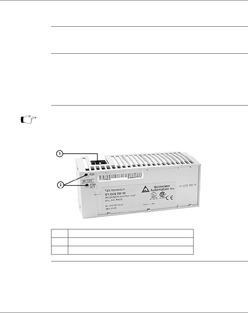
171 CCS 700 10
Overview This section describes the 171 CCS 700 10 Processor Adapter, including key
features, an illustration and specifications.
Key Features The key features of this Processor Adapter are:
lModbus Port 1
l64K bytes of internal memory
l32 MHz clock speed
Illustration The connector and LED indicators are shown in the following illustration:
Continued on next page
Note: The Modbus port connector looks like a Ethernet port connector. Do not
attempt to use an Modbus adapter as an Ethernet unit. Do not attempt to
place an Ethernet connector in a Modbus connector.
Label Description
1 Modbus Port 1 connector
2 LED indicators

Overview of Momentum M1 Processor Adapters
870 USE 101 10 V.2 33
171 CCS 700 10, Continued
LED Indicators This Processor Adapter has two LED indicators, RUN and COM ACT. Their
functions are described in the table below:
Specifications The following table contains specifications for the 171 CCS 700 10 Momentum M1
Processor Adapter:
Continued on next page
LED Status Function
Start up Both Single flash. Indicates good health.
RUN Green On continuously when the CPU has received power and is
solving logic.
Flashes an error pattern if the CPU is in kernel mode.
(See
Run LED Flash Patterns and Error Codes
on page 417)
Off CPU is not powered up or is not solving logic.
COM ACT Green May be on continuously or blinking. Indicates activity on
Modbus port 1.
Off No activity on Modbus port 1.
Memory
Internal Memory 64K bytes
User Memory 2.4K words
Flash RAM 256K bytes
Clock Speed 32 MHz
Input and Output References
Registers 2048
Discretes 2048 (any combination of 0
x
and 1
x
references)
I/O Servicing
Local I/O Services all the points on any host Momentum I/O base
Watchdog timeout 262 ms
Logic solve time 0.16 ms/k ladder logic instructions

Overview of Momentum M1 Processor Adapters
34 870 USE 101 10 V.2
171 CCS 700 10, Continued
Specifications,
Continued Mechanical
Weight 42.5 g (1.5 oz.)
Dimensions (HxDxW) 25.9x61.02x125mm
(1.01 x 2.37 x 4.86 in)
Material (Enclosures/
bezels)
Lexan
Operating Conditions
Temperature 0 ... 60 degrees C
Humidity 5 ... 95% (noncondensing)
Chemical interactions Enclosures and bezels are made of Lexan,
a polycarbonate that can be damaged by strong
alkaline solutions
Altitude, full operation 2000m (6500ft)
Vibration 10 ... 57Hz @ 0.075mm displacement amplitude
57...150Hz @ 1g
Ref. IEC 68-2-6 FC
Shock +/-15g peak, 11ms, half sine wave
Ref. IEC 68-2-27 EA
RFI Susceptibility/
immunity
Meets CE mark requirements for open equipment.
Open equipment should be installed in an industry-
standard enclosure, with access restricted to qualified
service personnel.
Storage Conditions
Temperature -40...+85 degrees C
Humidity 5 ... 95% (noncondensing)
Safety Parameters
Degree of protection Unintentional access (UL 508 Type 1, NEMA250 Type 1,
IP20 conforming to IEC529)
Di-electric strength RS232 is non-isolated from logic common
Agency Approvals UL 508, CSA, CUL, CE
FM class1, div2
Overview of Momentum M1 Processor Adapters
870 USE 101 10 V.2 35
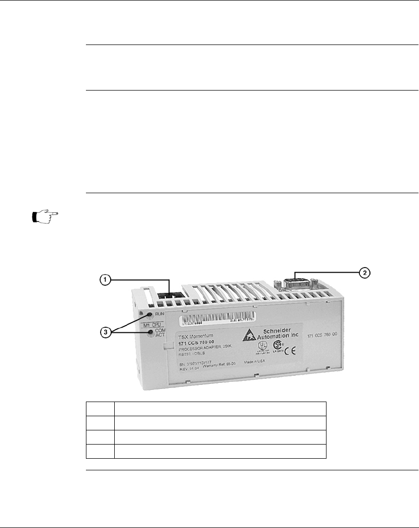
171 CCS 760 00
Overview This section describes the 171 CCS 760 00 Processor Adapter, including key
features, an illustration and specifications.
Key Features The key features of this Processor Adapter are:
lModbus Port 1
lI/OBus port
l256K bytes of internal memory
l20 MHz clock speed
Illustration The connectors and LED indicators are shown in the following illustration:
Continued on next page
Note: The Modbus port connector looks like a Ethernet port connector. Do not
attempt to use an Modbus adapter as an Ethernet unit. Do not attempt to
place an Ethernet connector in a Modbus connector.
Label Description
1 Modbus Port 1 connector
2 I/OBus port connector
3 LED indicators

Overview of Momentum M1 Processor Adapters
36 870 USE 101 10 V.2
171 CCS 760 00, Continued
LED Indicators This Processor Adapter has two LED indicators, RUN and COM ACT. Their
functions are described in the table below:
Specifications The following table contains specifications for the 171 CCS 760 00 Momentum M1
Processor Adapter:
Continued on next page
LED Status Function
Start up Both Single flash. Indicates good health.
RUN Green On continuously when the CPU has received power and is
solving logic.
Flashes an error pattern if the CPU is in kernel mode.
(See
Run LED Flash Patterns and Error Codes
on page 417)
Off CPU is not powered up or is not solving logic.
COM ACT Green May be on continuously or blinking. Indicates activity on
Modbus port 1.
Off No activity on Modbus port 1.
Memory
Internal Memory 256K bytes
User Memory 12K words 984LL Exec
160K words IEC Exec
Flash RAM 256K bytes
Clock Speed 20 MHz
984LL Input and Output References
Registers 4096
Discretes 2048 (any combination of 0
x
and 1
x
references) 984LL
IEC Input and Output References
Registers 4096
Discretes 2048 (any combination of 0
x
and 1
x
references)

Overview of Momentum M1 Processor Adapters
870 USE 101 10 V.2 37
171 CCS 760 00, Continued
Specifications,
Continued I/O Servicing
Local I/O Services all the points on any host Momentum I/O base
Watchdog timeout 419 ms
Logic solve time 0.25 ms/k ladder logic instructions
Mechanical
Weight 42.5 g (1.5 oz.)
Dimensions (HxDxW) 25.9x61.02x125mm
(1.01 x 2.37 x 4.86 in)
Material (Enclosures/
bezels)
Lexan
Operating Conditions
Temperature 0 ... 60 degrees C
Humidity 5 ... 95% (noncondensing)
Chemical interactions Enclosures and bezels are made of Lexan,
a polycarbonate that can be damaged by strong
alkaline solutions
Altitude, full operation 2000m (6500ft)
Vibration 10 ... 57Hz @ 0.075mm displacement amplitude
57...150Hz @ 1g
Ref. IEC 68-2-6 FC
Shock +/-15g peak, 11ms, half sine wave
Ref. IEC 68-2-27 EA
RFI Susceptibility/
immunity
Meets CE mark requirements for open equipment.
Open equipment should be installed in an industry-
standard enclosure, with access restricted to qualified
service personnel.
Storage Conditions
Temperature -40 ... +85 degrees C
Humidity 5 ... 95% (noncondensing)
Safety Parameters
Degree of protection Unintentional access (UL 508 Type 1, NEMA250 Type 1,
IP20 conforming to IEC529)
Di-electric strength RS232 and I/OBus are non-isolated from logic common
Ground continuity 30 A test on the exposed metal connector
Agency Approvals UL 508, CSA, CUL, CE
FM class1, div2
Overview of Momentum M1 Processor Adapters
38 870 USE 101 10 V.2
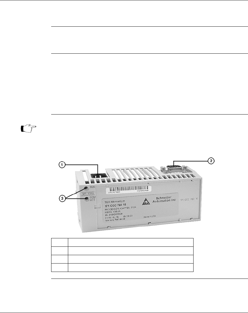
171 CCC 760 10
Overview This section describes the 171 CCC 760 10 Processor Adapter, including key
features, an illustration and specifications.
Key Features The key features of this Processor Adapter are:
lModbus Port 1
lI/OBus port
l512K bytes of internal memory
l32 MHz clock speed
Illustration The connectors and LED indicators are shown in the following illustration:
Continued on next page
Note: The Modbus port connector looks like a Ethernet port connector. Do not
attempt to use an Modbus adapter as an Ethernet unit. Do not attempt to
place an Ethernet connector in a Modbus connector.
Label Description
1 Modbus Port 1 connector
2 I/OBus port connector
3 LED indicators

Overview of Momentum M1 Processor Adapters
870 USE 101 10 V.2 39
171 CCC 760 10, Continued
LED Indicators This Processor Adapter has two LED indicators, RUN and COM ACT. Their
functions are described in the table below:
Specifications The following table contains specifications for the 171 CCC 760 10 Momentum M1
Processor Adapter:
Continued on next page
LED Status Function
Start up Both Single flash. Indicates good health.
RUN Green On continuously when the CPU has received power and is
solving logic.
Flashes an error pattern if the CPU is in kernel mode.
(See
Run LED Flash Patterns and Error Codes
on page 417)
Off CPU is not powered up or is not solving logic.
COM ACT Green May be on continuously or blinking. Indicates activity on
Modbus port 1.
Off No activity on Modbus port 1.
Memory
Internal Memory 512K bytes
User Memory 18K words 984LL Exec
240K words IEC Exec
Flash RAM 512K bytes
Clock Speed 32 MHz
984LL Input and Output References
Registers 26048
Discretes 8192 0
x
references
8192 1
x
references
IEC Input and Output References
Registers 26048
Discretes 8192 0
x
references
8192 1
x
references

Overview of Momentum M1 Processor Adapters
40 870 USE 101 10 V.2
171 CCC 760 10, Continued
Specifications,
Continued I/O Servicing
Local I/O Services all the points on any host Momentum I/O base
Watchdog timeout 262 ms
Logic solve time 0.16 ms/k ladder logic instructions
Mechanical
Weight 42.5 g (1.5 oz.)
Dimensions (HxDxW) 25.9x61.02x125mm
(1.01 x 2.37 x 4.86 in)
Material (Enclosures/
bezels)
Lexan
Operating Conditions
Temperature 0 ... 60 degrees C
Humidity 5 ... 95% (noncondensing)
Chemical interactions Enclosures and bezels are made of Lexan,
a polycarbonate that can be damaged by strong
alkaline solutions
Altitude, full operation 2000m (6500ft)
Vibration 10 ... 57Hz @ 0.075mm displacement amplitude
57...150Hz @ 1g
Ref. IEC 68-2-6 FC
Shock +/-15g peak, 11ms, half sine wave
Ref. IEC 68-2-27 EA
RFI Susceptibility/
immunity
Meets CE mark requirements for open equipment.
Open equipment should be installed in an industry-
standard enclosure, with access restricted to qualified
service personnel.
Storage Conditions
Temperature -40 ... +85 degrees C
Humidity 5 ... 95% (noncondensing)
Safety Parameters
Degree of protection Unintentional access (UL 508 Type 1, NEMA250 Type 1,
IP20 conforming to IEC529)
Di-electric strength RS232 and I/OBus are non-isolated from logic common
Ground continuity 30 A test on the exposed metal connector
Agency Approvals UL 508, CSA, CUL, CE
FM class1, div2
Overview of Momentum M1 Processor Adapters
870 USE 101 10 V.2 41
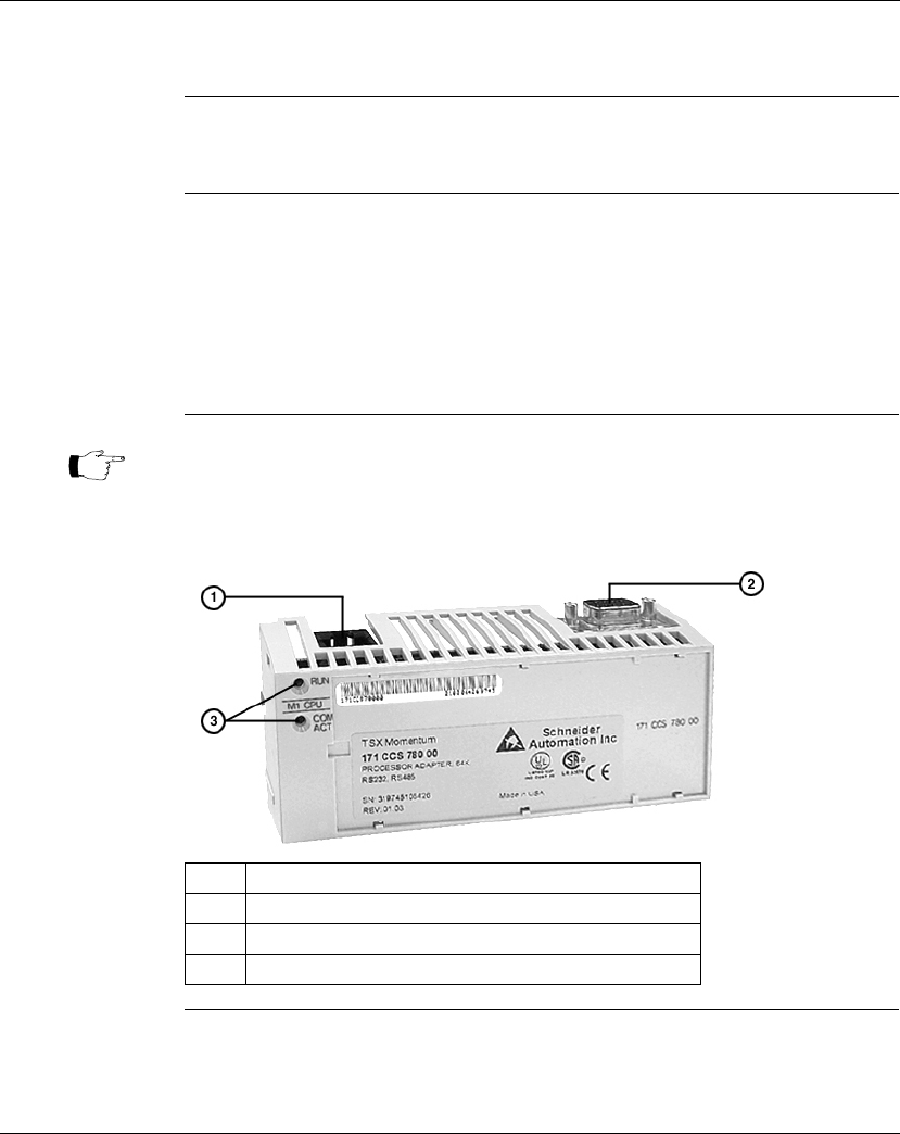
171 CCS 780 00
Overview This section describes the 171 CCS 780 00 Processor Adapter, including key
features, an illustration and specifications.
Key Features The key features of this Processor Adapter are:
lModbus Port 1
lModbus Port 2
l64K bytes of internal memory
l20 MHz clock speed
Illustration The connectors and LED indicators are shown in the following illustration:
Continued on next page
Note: The Modbus port connector looks like a Ethernet port connector. Do not
attempt to use an Modbus adapter as an Ethernet unit. Do not attempt to
place an Ethernet connector in a Modbus connector.
Label Description
1 Modbus Port 1 connector
2 Modbus Port 2 connector
3 LED indicators

Overview of Momentum M1 Processor Adapters
42 870 USE 101 10 V.2
171 CCS 780 00, Continued
LED Indicators This Processor Adapter has two LED indicators, RUN and COM ACT. Their
functions are described in the table below:
Specifications The following table contains specifications for the 171 CCS 780 00 Momentum M1
Processor Adapter:
Continued on next page
LED Status Function
Start up Both Single flash. Indicates good health.
RUN Green On continuously when the CPU has received power and is
solving logic.
Flashes an error pattern if the CPU is in kernel mode.
(See
Run LED Flash Patterns and Error Codes
on page 417)
Off CPU is not powered up or is not solving logic.
COM ACT Green May be on continuously or blinking. Indicates activity on
Modbus port 1.
Off No activity on Modbus port 1.
Memory
Internal Memory 64K bytes
User Memory 2.4K words
Flash RAM 256K bytes
Clock Speed 20 MHz
984LL Input and Output References
Registers 2048
Discretes 2048 (any combination of 0
x
and 1
x
references)
IEC Input and Output References
Registers 2048
Discretes 2048 (any combination of 0
x
and 1
x
references)
I/O Servicing
Local I/O Services all the points on any host Momentum I/O base
Watchdog timeout 419 ms
Logic solve time 0.25 ms/k ladder logic instructions

Overview of Momentum M1 Processor Adapters
870 USE 101 10 V.2 43
171 CCS 780 00, Continued
Specifications,
Continued Mechanical
Weight 42.5 g (1.5 oz.)
Dimensions (HxDxW) 25.9x61.02x125mm
(1.01 x 2.37 x 4.86 in)
Material (Enclosures/
bezels)
Lexan
Operating Conditions
Temperature 0 ... 60 degrees C
Humidity 5 ... 95% (noncondensing)
Chemical interactions Enclosures and bezels are made of Lexan,
a polycarbonate that can be damaged by strong
alkaline solutions
Altitude, full operation 2000m (6500ft)
Vibration 10 ... 57Hz @ 0.075mm displacement amplitude
57...150Hz @ 1g
Ref. IEC 68-2-6 FC
Shock +/-15g peak, 11ms, half sine wave
Ref. IEC 68-2-27 EA
RFI Susceptibility/
immunity
Meets CE mark requirements for open equipment.
Open equipment should be installed in an industry-
standard enclosure, with access restricted to qualified
service personnel.
Storage Conditions
Temperature -40 ... +85 degrees C
Humidity 5 ... 95% (noncondensing)
Safety Parameters
Degree of protection Unintentional access (UL 508 Type 1, NEMA250 Type 1,
IP20 conforming to IEC529)
Di-electric strength RS232 and RS485 are non-isolated from logic common
Ground continuity 30 A test on the exposed metal connector
Agency Approvals UL 508, CSA, CUL, CE
FM class1, div2
Overview of Momentum M1 Processor Adapters
44 870 USE 101 10 V.2
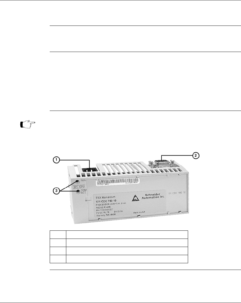
171 CCC 780 10
Overview This section describes the 171 CCC 780 10 Processor Adapter, including key
features, an illustration and specifications.
Key Features The key features of this Processor Adapter are:
lModbus Port 1
lModbus Port 2
l512K bytes of internal memory
l32 MHz clock speed
Illustration The connectors and LED indicators are shown in the following illustration:
Continued on next page
Note: The Modbus port connector looks like a Ethernet port connector. Do not
attempt to use an Modbus adapter as an Ethernet unit. Do not attempt to
place an Ethernet connector in a Modbus connector.
Label Description
1 Modbus Port 1 connector
2 Modbus Port 2 connector
3 LED indicators

Overview of Momentum M1 Processor Adapters
870 USE 101 10 V.2 45
171 CCC 780 10, Continued
LED Indicators This Processor Adapter has two LED indicators, RUN and COM ACT. Their
functions are described in the table below:
Specifications The following table contains specifications for the 171 CCC 780 10 Momentum M1
Processor Adapter:
LED Status Function
Start up Both Single flash. Indicates good health.
RUN Green On continuously when the CPU has received power and is
solving logic.
Flashes an error pattern if the CPU is in kernel mode.
(See
Run LED Flash Patterns and Error Codes
on page 417)
Off CPU is not powered up or is not solving logic.
COM ACT Green May be on continuously or blinking. Indicates activity on
Modbus port 1.
Off No activity on Modbus port 1.
Memory
Internal Memory 512K bytes
User Memory 18K words 984LL Exec
240k words IEC Exec
Flash RAM 512K bytes
Clock Speed 32 MHz
984LL Input and Output References
Registers 26048
Discretes 8192 0
x
references
8192 1
x
references
IEC Input and Output References
Registers 26048
Discretes 8192 0
x
references
8192 1
x
references
I/O Servicing
Local I/O Services all the points on any host Momentum I/O base
Watchdog timeout 262 ms
Logic solve time 0.16 ms/k ladder logic instructions

Overview of Momentum M1 Processor Adapters
46 870 USE 101 10 V.2
171 CCC 780 10, Continued
Specifications,
Continued Mechanical
Weight 42.5 g (1.5 oz.)
Dimensions (HxDxW) 25.9x61.02x125mm
(1.01 x 2.37 x 4.86 in)
Material (Enclosures/
bezels)
Lexan
Operating Conditions
Temperature 0 ... 60 degrees C
Humidity 5 ... 95% (noncondensing)
Chemical interactions Enclosures and bezels are made of Lexan,
a polycarbonate that can be damaged by strong
alkaline solutions
Altitude, full operation 2000m (6500ft)
Vibration 10 ... 57Hz @ 0.075mm displacement amplitude
57...150Hz @ 1g
Ref. IEC 68-2-6 FC
Shock +/-15g peak, 11ms, half sine wave
Ref. IEC 68-2-27 EA
RFI Susceptibility/
immunity
Meets CE mark requirements for open equipment.
Open equipment should be installed in an industry-
standard enclosure, with access restricted to qualified
service personnel.
Storage Conditions
Temperature -40 ... +85 degrees C
Humidity 5 ... 95% (noncondensing)
Safety Parameters
Degree of protection Unintentional access (UL 508 Type 1, NEMA250 Type 1,
IP20 conforming to IEC529)
Di-electric strength RS232 and RS485 are non-isolated from logic common
Ground continuity 30 A test on the exposed metal connector
Agency Approvals UL 508, CSA, CUL, CE
FM class1, div2
Overview of Momentum M1 Processor Adapters
870 USE 101 10 V.2 47
171 CCC 960 20
Overview This section describes the 171 CCC 960 20 Processor Adapter, including key
features, a illustration and specifications.
Key Features The key features of this Processor Adapter are:
lEthernet port
lI/OBus port
l544K bytes of internal memory
l50 MHz clock speed
Illustration The connectors and LED indicators are shown in the following illustration:
Continued on next page
Note: The Ethernet port connector looks like a Modbus port connector. Do not
attempt to use an Ethernet adapter as a Modbus unit. Do not attempt to
place a Modbus connector in an Ethernet connector.
Label Description
1 Ethernet port connector
2 I/OBus port connector
3 LED indicators

Overview of Momentum M1 Processor Adapters
48 870 USE 101 10 V.2
171 CCC 960 20, Continued
LED Indicators This Processor Adapter has three LED indicators, RUN, LAN ACT(IVE), and LAN
ST(ATUS). Their functions are described in the table below:
Specifications The following table contains specifications for the 171 CCC 960 20 Momentum M1
Processor Adapter:
Continued on next page
LED Indicato
r
Pattern
Status
Start up Both Single flash. Indicates good health.
RUN Green On continuously when the CPU has received power and is
solving logic.
Flashes an error pattern if the CPU is in kernel mode. (See
Run
LED Flash Patterns and Error Codes
on page 417)
Off CPU is not powered up or is not solving logic.
LAN ACT Green May be on continuously or blinking. Indicates activity on
Ethernet port.
Off No activity on Ethernet port.
LAN ST Green On continuously during normal operation.
Fast blink indicates normal Ethernet initialization at power-up.
3 flashes indicates no 10BASE-T link pulse detected. Check
cable and hub.
4 flashes indicates duplicate IP address detected.
5 flashes indicates no IP address available.
Off No valid MAC address.
Memory
Internal Memory 544K bytes
User Memory 18K words
Flash RAM 512K bytes
Clock Speed 50 MHz

Overview of Momentum M1 Processor Adapters
870 USE 101 10 V.2 49
171 CCC 960 20, Continued
Specifications,
Continued
Continued on next page
Input and Output References
Registers 26048
Discretes 8192 0
x
references
8192 1
x
references
I/O Servicing
Local I/O Services all the points on any host Momentum I/O base
Watchdog timeout 335 ms
Logic solve time See formula, following
Mechanical
Weight 42.5 g (1.5 oz.)
Dimensions (HxDxW) 25.9x61.02x125mm
(1.01 x 2.37 x 4.86 in)
Material (Enclosures/
bezels)
Lexan
Operating Conditions
Temperature 0 ... 60 degrees C
Humidity 5 ... 95% (noncondensing)
Chemical interactions Enclosures and bezels are made of Lexan,
a polycarbonate that can be damaged by strong
alkaline solutions
Altitude, full operation 2000m (6500ft)
Vibration 10 ... 57Hz @ 0.075mm displacement amplitude
57...150Hz @ 1g
Ref. IEC 68-2-6 FC
Shock +/-15g peak, 11ms, half sine wave
Ref. IEC 68-2-27 EA
RFI Susceptibility/
immunity
Meets CE mark requirements for open equipment.
Open equipment should be installed in an industry-
standard enclosure, with access restricted to qualified
service personnel.

Overview of Momentum M1 Processor Adapters
50 870 USE 101 10 V.2
171 CCC 960 20, Continued
Specifications,
Continued
Scantime
Formula for
984LL Exec
The following formula applies to the M1E Processor Adapter with the 984LL exec.
Scan time = (0.25 msec/ethernet device + 0.002 msec/word) + 0.13 msec/K of
logic + 0.40 msec + MBPlustime
Example You have 50 ENT modules connected to a single M1E with a configured time of 50
Msec each, a total of 4k user logic and no MB+ card. The scan time for all modules
configured as fast as possible would be 12.5 Msec + 0.52 Msec + 0.40 Msec =
13.42 Msec. However, since the M1E will only communicate to 1/4 of the modules
(12.5 Msec/50 Msec = 1/4) on any given scan, the corrected average scan time
would be 1/4 x (12.5) + 0.52 + 0.40 ≅ 4.1 Msec.
Storage Conditions
Temperature -40 ... +85 degrees C
Humidity 5 ... 95% (noncondensing)
Safety Parameters
Degree of protection Unintentional access (UL 508 Type 1, NEMA250 Type 1,
IP20 conforming to IEC529)
Di-electric strength Ethernet is isolated from logic common 500 VDC
Ground continuity 30 A test on the exposed metal connector
Agency Approvals UL 508, CSA, CUL, CE
FM class1, div2
Note:
Modbus Plus communications will slow the M1E. If there is no MB+ ring card then
MBPlustime = 0.
If there is a MB+ ring card, then each scan will be extended 0.3 Msec
even if there is no
message
.
Modbus Messages will add from 1 to 2 msec per scan, depending on the length of the
message.
Note:
The formula above presumes that all MSTR blocks and all configured connections are
set to go as fast as possible. In this case the M1E will attempt to exchange data with
each device once per scan.
If several devices are configured to communicate on a timed basis that is substantially
larger than the scan time calculated, then the communications to those devices will be
spread out over several scans. See Example, below.

Overview of Momentum M1 Processor Adapters
870 USE 101 10 V.2 51
171 CCC 960 30
Overview This section describes the 171 CCC 960 30 Processor Adapter, including key
features, an illustration and specifications.
Key Features The key features of this Processor Adapter are:
lEthernet port
lI/OBus port
l544K bytes of internal memory
l50 MHz clock speed
Continued on next page
Note: The 171 CCC 960 30 units are shipped with the latest IEC exec installed.
Note: The 984LL exec used in the 171 CCC 960 30 will not operate in a
171 CCC 960 20
Note: The Ethernet port connector looks like a Modbus port connector. Do not
attempt to use an Ethernet adapter as a Modbus unit. Do not attempt to
place a Modbus connector in an Ethernet connector.
Overview of Momentum M1 Processor Adapters
52 870 USE 101 10 V.2
171 CCC 960 30, Continued
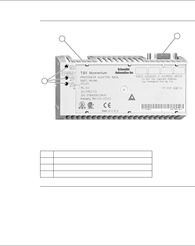
Illustration The connectors and LED indicators are shown in the following illustration:
Label Description
1 Ethernet port connector
2 I/OBus port connector
3 LED indicators
12
3

Overview of Momentum M1 Processor Adapters
870 USE 101 10 V.2 53
171 CCC 960 30, Continued
LED Indicators This Processor Adapter has three LED indicators, RUN, LAN ACT(IVE), and LAN
ST(ATUS). Their functions are described in the table below:
Specifications The following table contains specifications for the 171 CCC 960 30 Momentum M1
Processor Adapter:
Continued on next page
LED Indicator
Pattern Status
Start up Both Single flash. Indicates good health.
RUN Green On continuously when the CPU has received power and is
solving logic.
Flashes an error pattern if the CPU is in kernel mode. (See
Run
LED Flash Patterns and Error Codes
on page 417)
Off CPU is not powered up or is not solving logic.
LAN ACT Green May be on continuously or blinking. Indicates activity on
Ethernet port.
Off No activity on Ethernet port.
LAN ST Green On continuously during normal operation.
Fast blink indicates normal Ethernet initialization at power-up.
3 flashes indicates no 10BASE-T link pulse detected. Check
cable and hub.
4 flashes indicates duplicate IP address detected.
5 flashes indicates no IP address available.
Off No valid MAC address.
Memory
Internal Memory 544K bytes
User Memory 18K words 984LL Exec
200k words IEC Exec
Flash RAM 1 Megabyte
Clock Speed 50 MHz

Overview of Momentum M1 Processor Adapters
54 870 USE 101 10 V.2
171 CCC 960 30, Continued
Specifications,
Continued
Continued on next page
984LL Input and Output References
Registers 26048
Discretes 8192 0
x
references
8192 1
x
references
IEC Input and Output References
Registers 11200
Discretes 4096 0x references
4096 1x references
I/O Servicing
Local I/O Services all the points on any host Momentum I/O base
Watchdog timeout 335 ms
Logic solve time See formula, following
Mechanical
Weight 42.5 g (1.5 oz.)
Dimensions (HxDxW) 25.9x61.02x125mm
(1.01 x 2.37 x 4.86 in)
Material (Enclosures/
bezels)
Lexan
Operating Conditions
Temperature 0 ... 60 degrees C
Humidity 5 ... 95% (noncondensing)
Chemical interactions Enclosures and bezels are made of Lexan,
a polycarbonate that can be damaged by strong
alkaline solutions
Altitude, full operation 2000m (6500ft)
Vibration 10 ... 57Hz @ 0.075mm displacement amplitude
57...150Hz @ 1g
Ref. IEC 68-2-6 FC
Shock +/-15g peak, 11ms, half sine wave
Ref. IEC 68-2-27 EA
RFI Susceptibility/
immunity
Meets CE mark requirements for open equipment.
Open equipment should be installed in an industry-
standard enclosure, with access restricted to qualified
service personnel.

Overview of Momentum M1 Processor Adapters
870 USE 101 10 V.2 55
171 CCC 960 30, Continued
Specifications,
Continued
Scantime
Formula for
984LL Exec
The following formula applies to the M1E Processor Adapter with the 984LL exec.
Scan time = (0.25 msec/ethernet device + 0.002 msec/word) + 0.13 msec/K of
logic + 0.40 msec + MBPlustime
Example You have 50 ENT modules connected to a single M1E with a configured time of 50
Msec each, a total of 4k user logic and no MB+ card. The scan time for all modules
configured as fast as possible would be 12.5 Msec + 0.52 Msec + 0.40 Msec =
13.42 Msec. However, since the M1E will only communicate to 1/4 of the modules
(12.5 Msec/50 Msec = 1/4) on any given scan, the corrected average scan time
would be 1/4 x (12.5) + 0.52 + 0.40 ≅ 4.1 Msec.
Storage Conditions
Temperature -40 ... +85 degrees C
Humidity 5 ... 95% (noncondensing)
Safety Parameters
Degree of protection Unintentional access (UL 508 Type 1, NEMA250 Type 1,
IP20 conforming to IEC529)
Di-electric strength Ethernet is isolated from logic common 500 VDC
Ground continuity 30 A test on the exposed metal connector
Agency Approvals UL 508, CSA, CUL, CE
FM class1, div2
Note:
Modbus Plus communications will slow the M1E. If there is no MB+ ring card then
MBPlustime = 0.
If there is a MB+ ring card, then each scan will be extended 0.3 Msec
even if there is no
message
.
Modbus Messages will add from 1 to 2 msec per scan, depending on the length of the
message.
Note:
The formula above presumes that all MSTR blocks and all configured connections are
set to go as fast as possible. In this case the M1E will attempt to exchange data with
each device once per scan.
If several devices are configured to communicate on a timed basis that is substantially
larger than the scan time calculated, then the communications to those devices will be
spread out over several scans. See Example, below.
Overview of Momentum M1 Processor Adapters
56 870 USE 101 10 V.2
171 CCC 980 20
Overview This section describes the 171 CCC 980 20 Processor Adapter, including key
features, an illustration and specifications.
Key Features The key features of this Processor Adapter are:
lEthernet port
lModbus Port 2 / RS485 only
l544K bytes of internal memory
l50 MHz clock speed
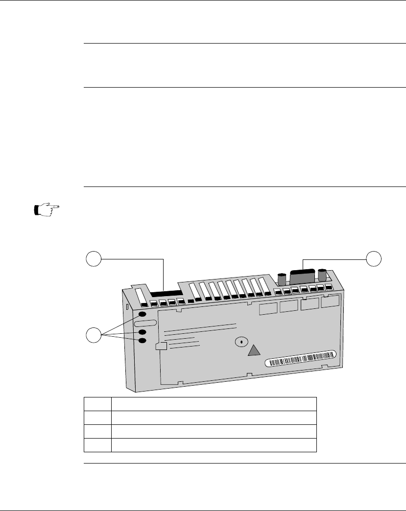
Illustration The connectors and LED indicators are shown in the following illustration.
Continued on next page
Note: The Ethernet port connector looks like a Modbus port connector. Do not
attempt to use an Ethernet adapter as a Modbus unit. Do not attempt to
place a Modbus connector in an Ethernet connector.
Label Description
1 Ethernet port connector
2 Modbus Port 2 connector
3 LED indicators
1
Schneider
Automation Inc.
TSX Momentum
3
2

Overview of Momentum M1 Processor Adapters
870 USE 101 10 V.2 57
171 CCC 980 20, Continued
LED Indicators This Processor Adapter has three LED indicators, RUN, LAN ACT(IVE), and LAN
ST(ATUS). Their functions are described in the table below:
Specifications The following table contains specifications for the 171 CCC 980 20 Momentum M1
Processor Adapter:
Continued on next page
LED Indicator
Pattern Status
Start up Both Single flash. Indicates good health.
RUN Green On continuously when the CPU has received power and is
solving logic.
Flashes an error pattern if the CPU is in kernel mode. (See
Run
LED Flash Patterns and Error Codes
on page 417)
Off CPU is not powered up or is not solving logic.
LAN ACT Green May be on continuously or blinking. Indicates activity on
Ethernet port.
Off No activity on Ethernet port.
LAN ST Green On continuously during normal operation.
Fast blink indicates normal Ethernet initialization at power-up.
3 flashes indicates no 10BASE-T link pulse detected. Check
cable and hub.
4 flashes indicates duplicate IP address detected.
5 flashes indicates no IP address available.
Off No valid MAC address.
Memory
Internal Memory 544K bytes
User Memory 18K words
Flash RAM 512K bytes
Clock Speed 50 MHz

Overview of Momentum M1 Processor Adapters
58 870 USE 101 10 V.2
171 CCC 980 20, Continued
Specifications,
Continued
Continued on next page
Input and Output References
Registers 26048
Discretes 8192 0
x
references
8192 1
x
references
I/O Servicing
Local I/O Services all the points on any host Momentum I/O base
Watchdog timeout 335 ms
Logic solve time See formula, following
Mechanical
Weight 42.5 g (1.5 oz.)
Dimensions (HxDxW) 25.9x61.02x125mm
(1.01 x 2.37 x 4.86 in)
Material (Enclosures/
bezels)
Lexan
Operating Conditions
Temperature 0 ... 60 degrees C
Humidity 5 ... 95% (noncondensing)
Chemical interactions Enclosures and bezels are made of Lexan,
a polycarbonate that can be damaged by strong
alkaline solutions
Altitude, full operation 2000m (6500ft)
Vibration 10 ... 57Hz @ 0.075mm displacement amplitude
57...150Hz @ 1g
Ref. IEC 68-2-6 FC
Shock +/-15g peak, 11ms, half sine wave
Ref. IEC 68-2-27 EA
RFI Susceptibility/
immunity
Meets CE mark requirements for open equipment.
Open equipment should be installed in an industry-
standard enclosure, with access restricted to qualified
service personnel.

Overview of Momentum M1 Processor Adapters
870 USE 101 10 V.2 59
171 CCC 980 20, Continued
Specifications,
Continued
Scantime
Formula for
984LL Exec
The following formula applies to the M1E Processor Adapter with the 984LL exec.
Scan time = (0.25 msec/ethernet device + 0.002 msec/word) + 0.13 msec/K of
logic + 0.40 msec + MBPlustime
Example You have 50 ENT modules connected to a single M1E with a configured time of 50
Msec each, a total of 4k user logic and no MB+ card. The scan time for all modules
configured as fast as possible would be 12.5 Msec + 0.52 Msec + 0.40 Msec =
13.42 Msec. However, since the M1E will only communicate to 1/4 of the modules
(12.5 Msec/50 Msec = 1/4) on any given scan, the corrected average scan time
would be 1/4 x (12.5) + 0.52 + 0.40 ≅ 4.1 Msec.
Storage Conditions
Temperature -40 ... +85 degrees C
Humidity 5 ... 95% (noncondensing)
Safety Parameters
Degree of protection Unintentional access (UL 508 Type 1, NEMA250 Type 1,
IP20 conforming to IEC529)
Di-electric strength Ethernet is isolated from logic common 500 VDC
Ground continuity 30 A test on the exposed metal connector
Agency Approvals UL 508, CSA, CUL, CE
FM class1, div2
Note:
Modbus Plus communications will slow the M1E. If there is no MB+ ring card then
MBPlustime = 0.
If there is a MB+ ring card, then each scan will be extended 0.3 Msec
even if there is no
message
.
Modbus Messages will add from 1 to 2 msec per scan, depending on the length of the
message.
Note:
The formula above presumes that all MSTR blocks and all configured connections are
set to go as fast as possible. In this case the M1E will attempt to exchange data with
each device once per scan.
If several devices are configured to communicate on a timed basis that is substantially
larger than the scan time calculated, then the communications to those devices will be
spread out over several scans. See Example, below.

Overview of Momentum M1 Processor Adapters
60 870 USE 101 10 V.2
171 CCC 980 30
Overview This section describes the 171 CCC 980 30 Processor Adapter, including key
features, an illustration and specifications.
Key Features The key features of this Processor Adapter are:
lEthernet port
lModbus Port 2 / RS485 only
l544K bytes of internal memory
l50 MHz clock speed
Continued on next page
Note: The 171 CCC 980 30 units are shipped with the latest IEC exec installed.
Note: The 984LL exec used in the 171 CCC 980 30 will not operate in a
171 CCC 980 20
Note: The Ethernet port connector looks like a Modbus port connector. Do not
attempt to use an Ethernet adapter as a Modbus unit. Do not attempt to
place a Modbus connector in an Ethernet connector.
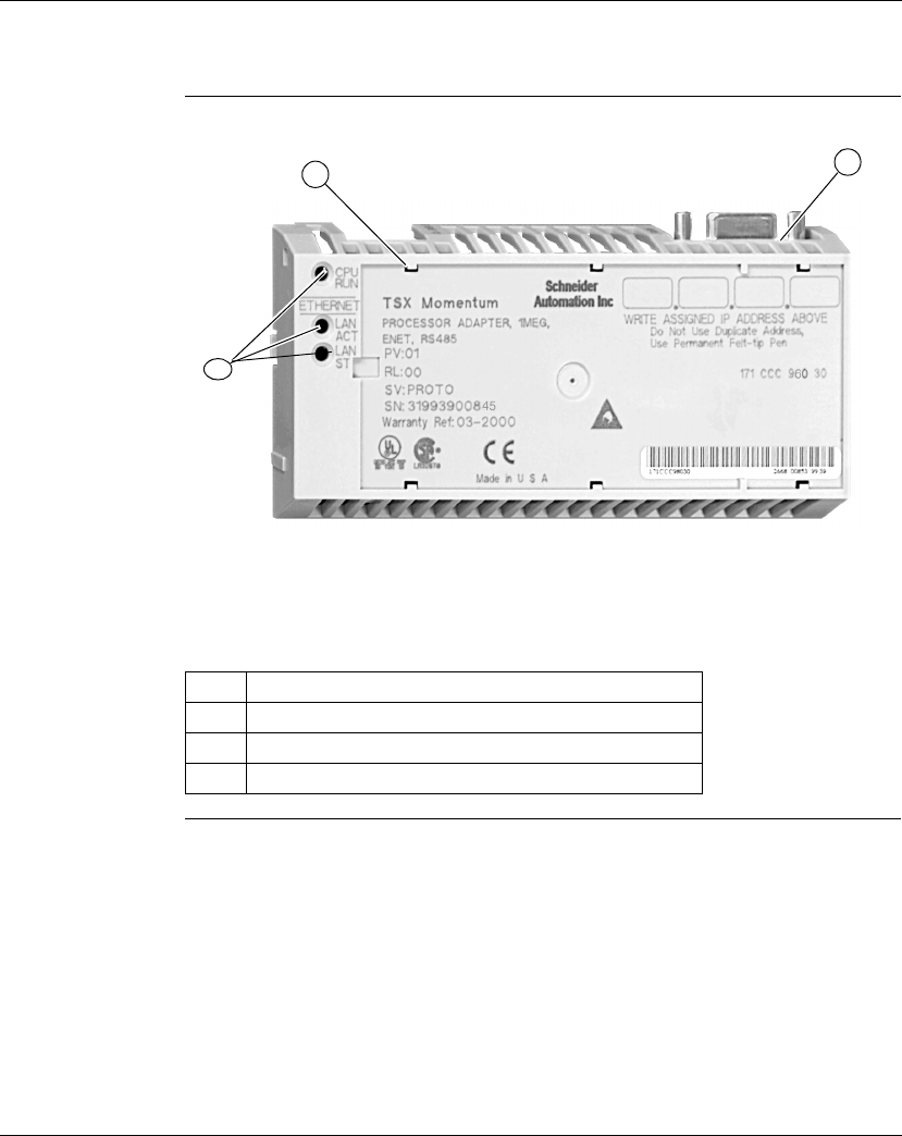
Overview of Momentum M1 Processor Adapters
870 USE 101 10 V.2 61
171 CCC 980 30, Continued
Illustration The connectors and LED indicators are shown in the following illustration:
Continued on next page
Label Description
1 Ethernet port connector
2 Modbus Port 2 connector
3 LED indicators
12
3

Overview of Momentum M1 Processor Adapters
62 870 USE 101 10 V.2
171 CCC 980 30, Continued
LED Indicators This Processor Adapter has three LED indicators, RUN, LAN ACT(IVE), and LAN
ST(ATUS). Their functions are described in the table below:
Specifications The following table contains specifications for the 171 CCC 980 30 Momentum M1
Processor Adapter:
Continued on next page
LED Indicator
Pattern Status
Start up Both Single flash. Indicates good health.
RUN Green On continuously when the CPU has received power and is
solving logic.
Flashes an error pattern if the CPU is in kernel mode. (See
Run
LED Flash Patterns and Error Codes
on page 417)
Off CPU is not powered up or is not solving logic.
LAN ACT Green May be on continuously or blinking. Indicates activity on
Ethernet port.
Off No activity on Ethernet port.
LAN ST Green On continuously during normal operation.
Fast blink indicates normal Ethernet initialization at power-up.
3 flashes indicates no 10BASE-T link pulse detected. Check
cable and hub.
4 flashes indicates duplicate IP address detected.
5 flashes indicates no IP address available.
Off No valid MAC address.
Memory
Internal Memory 544K bytes
User Memory 18K words 984LL Exec
200k words IEC Exec
Flash RAM 1 Megabyte
Clock Speed 50 MHz

Overview of Momentum M1 Processor Adapters
870 USE 101 10 V.2 63
171 CCC 980 30, Continued
Specifications,
Continued
Continued on next page
984LL Input and Output References
Registers 26048
Discretes 8192 0
x
references
8192 1
x
references
IEC Input and Output References
Registers 11200
Discretes 4096 0
x
references
4096 1
x
references
I/O Servicing
Local I/O Services all the points on any host Momentum I/O base
Watchdog timeout 335 ms
Logic solve time See formula, following
Mechanical
Weight 42.5 g (1.5 oz.)
Dimensions (HxDxW) 25.9x61.02x125mm
(1.01 x 2.37 x 4.86 in)
Material (Enclosures/
bezels)
Lexan
Operating Conditions
Temperature 0 ... 60 degrees C
Humidity 5 ... 95% (noncondensing)
Chemical interactions Enclosures and bezels are made of Lexan,
a polycarbonate that can be damaged by strong
alkaline solutions
Altitude, full operation 2000m (6500ft)
Vibration 10 ... 57Hz @ 0.075mm displacement amplitude
57...150Hz @ 1g
Ref. IEC 68-2-6 FC
Shock +/-15g peak, 11ms, half sine wave
Ref. IEC 68-2-27 EA
RFI Susceptibility/
immunity
Meets CE mark requirements for open equipment.
Open equipment should be installed in an industry-
standard enclosure, with access restricted to qualified
service personnel.

Overview of Momentum M1 Processor Adapters
64 870 USE 101 10 V.2
171 CCC 980 30, Continued
Specifications,
Continued
Scantime
Formula for
984LL Exec
The following formula applies to the M1E Processor Adapter with the 984LL exec.
Scan time = (0.25 msec/ethernet device + 0.002 msec/word) + 0.13 msec/K of
logic + 0.40 msec + MBPlustime
Example You have 50 ENT modules connected to a single M1E with a configured time of 50
Msec each, a total of 4k user logic and no MB+ card. The scan time for all modules
configured as fast as possible would be 12.5 Msec + 0.52 Msec + 0.40 Msec =
13.42 Msec. However, since the M1E will only communicate to 1/4 of the modules
(12.5 Msec/50 Msec = 1/4) on any given scan, the corrected average scan time
would be 1/4 x (12.5) + 0.52 + 0.40 ≅ 4.1 Msec.
Storage Conditions
Temperature -40 ... +85 degrees C
Humidity 5 ... 95% (noncondensing)
Safety Parameters
Degree of protection Unintentional access (UL 508 Type 1, NEMA250 Type 1,
IP20 conforming to IEC529)
Di-electric strength Ethernet is isolated from logic common 500 VDC
Ground continuity 30 A test on the exposed metal connector
Agency Approvals UL 508, CSA, CUL, CE
FM class1, div2
Note:
Modbus Plus communications will slow the M1E. If there is no MB+ ring card then
MBPlustime = 0.
If there is a MB+ ring card, then each scan will be extended 0.3 Msec
even if there is no
message
.
Modbus Messages will add from 1 to 2 msec per scan, depending on the length of the
message.
Note:
The formula above presumes that all MSTR blocks and all configured connections are
set to go as fast as possible. In this case the M1E will attempt to exchange data with
each device once per scan.
If several devices are configured to communicate on a timed basis that is substantially
larger than the scan time calculated, then the communications to those devices will be
spread out over several scans. See Example, below.

870 USE 101 10 V.2 65
Overview of Momentum Option
Adapters
At a Glance
Purpose An Option Adapter can be inserted between the Processor Adapter and the I/O
base to provide:
lA battery backup for the CPU
lA time-of-day clock
lExtra communication ports
This chapter describes the three types of Momentum Option Adapters.
In This Chapter This chapter contains the following sections:
For This Topic... See Section... On Page...
Introducing the Momentum Option Adapters 1 66
Serial Option Adapter 2 67
Modbus Plus Option Adapter 3 73
Redundant Modbus Plus Option Adapter 4 79

Option Adapters
66 870 USE 101 10 V.2
Section 2.1
Introducing the Momentum Option Adapters
Basic Features of Option Adapters
Introduction This section describes the basic features of all Option Adapters:
lBatteries
lA time-of-day (TOD) clock
lCommunication port(s)
Batteries The batteries back up the CPU’s user program and state RAM.
Time-of-Day
Clock The time-of-day clock allows you to use the date and time as an element in your
user program.
Communication
Ports The three Momentum Option Adapters are distinguished by the communications
ports they offer, as shown in the table below:
Option Adapter Communication Port(s)
172 JNN 210 32 Software-selectable RS232/RS485 serial port
172 PNN 210 22 One Modbus Plus port
172 PNN 260 22 Two Modbus Plus ports for a redundant (back-up) cable run

Option Adapters
870 USE 101 10 V.2 67
Section 2.2
Serial Option Adapter
Overview
Purpose This section describes the 172 JNN 210 32 Serial Option Adapter, including the
front panel components and specifications.
In This Section This section includes the following topics:
For This Topic... See Page...
Front Panel Components 68
Specifications 71
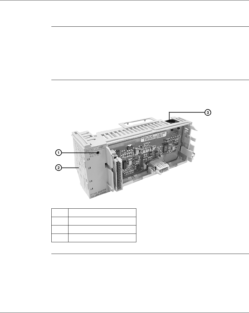
Option Adapters
68 870 USE 101 10 V.2
Front Panel Components
Overview The front panel includes:
lAn LED indicator
lBattery compartment
lModbus Port 2 connector
Illustration The illustration below shows the location of LED indicator, the battery compartment,
and the Modbus Port 2 connector.
Continued on next page
Label Description
1 LED indicator
2 Battery compartment door
3 Modbus Port 2 connector

Option Adapters
870 USE 101 10 V.2 69
Front Panel Components, Continued
LED Indicator This Option Adapter has one LED indicator, the Com Act indicator. Its functions are
described in the table below.
Modbus Port 2 Modbus Port 2 is a general-purpose asynchronous serial port with user-selectable
RS232/RS485 slave functionality. The choice between RS232 and RS485 is made
in the software.
Auto-Logout
Feature On
Modbus Port 2
If the RS232 port is chosen, auto-logout is supported. If a programming panel is
logged into the CPU via the serial port and its cable gets disconnected, the
Processor Adapter automatically logs out the port. This auto-logout feature is
designed to prevent a lock-up situation that could prevent other host stations from
logging in on other ports.
Auto-logout is not available for any RS485 port, including the RS485 option on the
Serial Option Adapter. The user must log out of the processor using the
programming software.
Continued on next page
LED Status Function
COM ACT Green May be on steadily or blinking. Indicates activity on the RS232/
RS485 serial port.
Off No activity on the RS232/RS485 serial port.
Note: When this Option Adapter is assembled with a 171 CCS 780 00
Processor Adapter or a 171 CCC 780 10 Processor Adapter (with built-in
Modbus Port 2), the Modbus Port 2 on the Option Adapter is electrically
disabled. The TOD clock and the battery backup on the Option Adapter
remain functional.

Option Adapters
70 870 USE 101 10 V.2
Front Panel Components, Continued
Pinouts for
Modbus Port 2 The 172 JNN 210 32 Serial Option Adapter uses the following pinouts:
Pin For RS232 For RS485
1 DTR RXD -
2 DSR RXD +
3TXD TXD +
4RXD
5 signal common signal common
6RTS TXD -
7CTS
8 cable shield cable shield

Option Adapters
870 USE 101 10 V.2 71
Specifications
Specifications This section provides the specifications for the 172 JNN 210 32 Momentum Serial
Option Adapter:
Continued on next page
Mechanical
Weight 85.05 g (3 oz.)
Dimensions (HxDxW) 58.3 (on battery side) x 60.6 x 143.1mm
(2.27 x 2.36 x 5.57 in)
Material (Enclosures/bezels) Lexan
Time-of-Day Clock
Accuracy +/- 13 s/day
Batteries
Type AAA alkaline, two required
two included with Option Adapter (in separate package)
Service life < 30 days from the time a battery-low indication is received
to actual battery failure @ 40degrees C maximum ambient
temperature with the system continuously powered down.
Shelf life In excess of 5 yr. @ room temperature
Operating Conditions
Temperature 0 ... 60 degrees C
Humidity 5 ... 95% (noncondensing)
Chemical interactions Enclosures and bezels are made of Lexan,
a polycarbonate that can be damaged by strong
alkaline solutions
Altitude, full operation 2000m (6500ft)
Vibration 10 ... 57Hz @ 0.075mm displacement amplitude
57...150Hz @ 1g
Ref. IEC 68-2-6 FC
Shock +/-15g peak, 11ms, half sine wave
Ref. IEC 68-2-27 EA

Option Adapters
72 870 USE 101 10 V.2
Specifications, Continued
Specifications,
Continued RFI Susceptibility/ immunity Meets CE mark requirements for open equipment.
Open equipment should be installed in an industry-standard
enclosure, with access restricted to qualified service
personnel.
Storage Conditions
Temperature -40...+85 degrees C
Humidity 5 ... 95% (noncondensing)
Safety Parameters
Degree of protection Unintentional access (UL 508 Type 1, NEMA250 Type 1,
IP20 conforming to IEC529)
Di-electric strength RS232/485 is non-isolated from logic common
Agency Approvals UL 508, CSA, CUL, CE
FM class1, div2 pending

Option Adapters
870 USE 101 10 V.2 73
Section 2.3
Modbus Plus Option Adapter
Overview
Purpose This section describes the 172 PNN 210 22 Modbus Plus Option Adapter, including
the front panel components and specifications.
In This Section This section contains the following topics:
For This Topic... See Page...
Front Panel Components 74
Specifications 77

Option Adapters
74 870 USE 101 10 V.2
Front Panel Components
Overview The front panel includes:
lAn LED indicator
lBattery compartment
lAddress switches
l9-pin D-shell connector for Modbus Plus communications
Illustration The illustration below shows the LED indicator, address switches, Modbus Plus
connector, and battery compartment.
Continued on next page
Label Description
1 LED indicator
2 Battery compartment door
3 Address switches for Modbus Plus
4 9-pin D-shell connector for Modbus Plus
communications (port A)

Option Adapters
870 USE 101 10 V.2 75
Front Panel Components, Continued
LED Indicator This Option Adapter has one LED indicator, the MB+ ACT indicator. This indicator
flashes the following patterns, based on the status of the Modbus Plus node:
Continued on next page
Pattern Meaning
6 flashes/s This is the normal operating state for the node. It is receiving
and passing the network token. All nodes on a healthy
network flash this pattern.
1 flash/s The node is offline just after power-up or after exiting the
6 flashes/s mode. In this state, the node monitors the
network and builds a table of active nodes. After being in
this state for 5s, the node attempts to go to its normal
operating state, indicated by 6 flashes/s.
2 flashes, then OFF for 2s The node detects the token being passed among the other
nodes, but never receives the token. Check the network for
an open circuit or defective termination.
3 flashes, then OFF for 1.7s The node is not detecting any tokens being passed among
the other nodes. It periodically claims the token but cannot
find another node to which to pass it. Check the network for
an open circuit or defective termination.
4 flashes, then OFF for 1.4s The node has detected a valid message from a node using a
network address identical to its own address. The node
remains in this state for as long as it continues to detect the
duplicate address. If the duplicate address is not detected
for 5s, the node changes to its 1 flash/s mode.
ON Indicates an invalid node address.
OFF Possible fault with Modbus Plus Option Adapter.
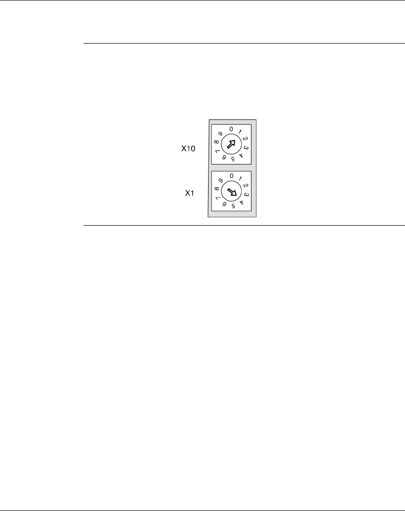
Option Adapters
76 870 USE 101 10 V.2
Front Panel Components, Continued
Modbus Plus
Address
Switches
The two rotary switches on the Option Adapter are used to set a Modbus Plus node
address for the CPU module. The switches are shown in the following illustration.
Their usage is described in detail in
Modbus Plus Addresses
on page 198.
The switches in this illustration are set to address 14.

Option Adapters
870 USE 101 10 V.2 77
Specifications
Specifications This section provides the specifications for the 172 PNN 210 22 Momentum Serial
Option Adapter:
Continued on next page
Mechanical
Weight 85.05 g (3 oz.)
Dimensions (HxDxW) 58.3 (on battery side) x 60.6 x 143.1mm
(2.27 x 2.36 x 5.57 in)
Material (Enclosures/bezels) Lexan
Time-of-Day Clock
Accuracy +/- 13 s/day
Batteries
Type AAA alkaline, two required.
Two included with Option Adapter (in separate package).
Service life < 30 days from the time a battery-low indication is received
to actual battery failure @ 40degrees C maximum ambient
temperature with the system continuously powered down.
Shelf life In excess of 5 yr. @ room temperature
Operating Conditions
Temperature 0 ... 60 degrees C
Humidity 5 ... 95% (noncondensing)
Chemical interactions Enclosures and bezels are made of Lexan,
a polycarbonate that can be damaged by strong
alkaline solutions
Altitude, full operation 2000m (6500ft)
Vibration 10 ... 57Hz @ 0.075mm displacement amplitude
57...150Hz @ 1g
Ref. IEC 68-2-6 FC
Shock +/-15g peak, 11ms, half sine wave
Ref. IEC 68-2-27 EA

Option Adapters
78 870 USE 101 10 V.2
Specifications, Continued
Specifications,
Continued RFI Susceptibility/ immunity Meets CE mark requirements for open equipment.
Open equipment should be installed in an industry-standard
enclosure, with access restricted to qualified service
personnel.
Storage Conditions
Temperature -40...+85 degrees C
Humidity 5 ... 95% (noncondensing)
Safety Parameters
Degree of protection Unintentional access (UL 508 Type 1, NEMA250 Type 1,
IP20 conforming to IEC529)
Di-electric strength 500 V
Ground continuity 30 A test on the exposed metal connector
Agency Approvals UL 508, CSA, CUL, CE
FM class1, div2 pending

Option Adapters
870 USE 101 10 V.2 79
Section 2.4
Redundant Modbus Plus Option Adapter
Overview
Purpose This section describes the 172 PNN 260 22 Redundant Modbus Plus Option
Adapter, including the front panel components and specifications.
In This Section This section contains the following topics:
For This Topic... See Page...
Front Panel Components 80
Specifications 84
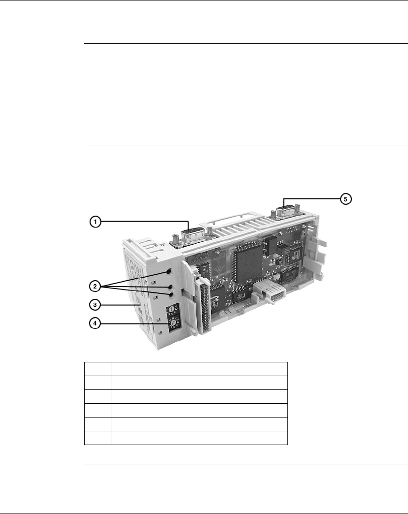
Option Adapters
80 870 USE 101 10 V.2
Front Panel Components
Overview The front panel includes:
lTwo 9-pin D-shell connectors for Modbus Plus communications
lThree LED indicators
lBattery compartment
lAddress switches
Illustration The illustration below shows the LED indicators, address switches, battery
compartment and Modbus Plus connectors.
Continued on next page
Label Description
1 9-pin D-shell connector for Modbus Plus port B
2 Array of three LED indicators
3 Battery compartment door
4 Address switches for Modbus Plus
5 9-pin D-shell connector for Modbus Plus port A

Option Adapters
870 USE 101 10 V.2 81
Front Panel Components, Continued
LED Indicators This Option Adapter has three LED indicators. Their functions are described in the
table below.
Continued on next page
LED Status Function
MB+ ACT Green Indicates activity on one or both of the Modbus Plus ports (see
the flash pattern table below)
Off No activity on either Modbus Plus port
ERR A Red Indicates a communications failure on Modbus Plus port A*
Off No problems detected on Modbus Plus port A
ERR B Red Indicates a communications failure on Modbus Plus port B*
Off No problems detected on Modbus Plus port B
* If you are not using redundant cabling on the Modbus Plus link (i.e., if only one of the ports
is being used) the Error LED for the unused port will be on constantly when Modbus Plus
communication occurs on the network.

Option Adapters
82 870 USE 101 10 V.2
Front Panel Components, Continued
MB+ ACT Flash
Patterns This table provides the patterns that the MB+ ACT indicator will flash to indicate the
status of the Modbus Plus node.
Continued on next page
Pattern Meaning
6 flashes/s This is the normal operating state for the node. It is
receiving and passing the network token. All nodes on a
healthy network flash this pattern.
1 flash/s The node is offline just after power-up or after exiting the
6 flashes/s mode. In this state, the node monitors the
network and builds a table of active nodes. After being in
this state for 5s, the node attempts to go to its normal
operating state, indicated by 6 flashes/s.
2 flashes, then OFF for 2s The node detects the token being passed among the other
nodes, but never receives the token. Check the network for
an open circuit or defective termination.
3 flashes, then OFF for 1.7s The node is not detecting any tokens being passed among
the other nodes. It periodically claims the token but cannot
find another node to which to pass it. Check the network for
an open circuit or defective termination.
4 flashes, then OFF for 1.4s The node has detected a valid message from a node using
a network address identical to its own address. The node
remains in this state for as long as it continues to detect the
duplicate address. If the duplicate address is not detected
for 5s, the node changes to its 1flash/s mode.
ON Indicates an invalid node address.
OFF Possible fault with Modbus Plus Option Adapter.
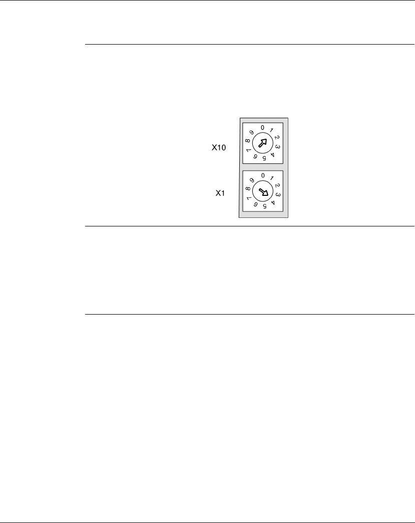
Option Adapters
870 USE 101 10 V.2 83
Front Panel Components, Continued
Modbus Plus
Address
Switches
The two rotary switches on the Option Adapter are used to set a Modbus Plus node
address for the CPU module. The switches are shown in the following illustration.
Their usage is described in detail in
Modbus Plus Addresses
on page 198.
The switches in this illustration are set to address 14.
Modbus Plus
Ports A and B This Option Adapter has two Modbus Plus ports. Redundant cabling on the
Modbus Plus network offers increased protection against cable faults or excessive
noise bursts on either one of the two cable paths. When one of the channels
experiences communication problems, error-free messaging can continue to be
processed on the alternate path.

Option Adapters
84 870 USE 101 10 V.2
Specifications
Specifications This section provides the specifications for the 172 PNN 260 22 Momentum Serial
Option Adapter:
Continued on next page
Mechanical
Weight 85.05 g (3 oz.)
Dimensions (HxDxW) 58.3 (on battery side) x 60.6 x 143.1mm
(2.27 x 2.36 x 5.57 in)
Material (Enclosures/bezels) Lexan
Time-of-Day Clock
Accuracy +/- 13 s/day
Batteries
Type AAA alkaline, two required.
Two included with Option Adapter (in separate package).
Service life < 30 days from the time a battery-low indication is received
to actual battery failure @ 40degrees C maximum ambient
temperature with the system continuously powered down.
Shelf life In excess of 5 yr. @ room temperature
Operating Conditions
Temperature 0 ... 60 degrees C
Humidity 5 ... 95% (noncondensing)
Chemical interactions Enclosures and bezels are made of Lexan,
a polycarbonate that can be damaged by strong
alkaline solutions
Altitude, full operation 2000m (6500ft)
Vibration 10 ... 57Hz @ 0.075mm displacement amplitude
57...150Hz @ 1g
Ref. IEC 68-2-6 FC
Shock +/-15g peak, 11ms, half sine wave
Ref. IEC 68-2-27 EA

Option Adapters
870 USE 101 10 V.2 85
Specifications, Continued
Specifications,
Continued RFI Susceptibility/ immunity Meets CE mark requirements for open equipment.
Open equipment should be installed in an industry-standard
enclosure, with access restricted to qualified service
personnel.
Storage Conditions
Temperature -40...+85 degrees C
Humidity 5 ... 95% (noncondensing)
Safety Parameters
Degree of protection Unintentional access (UL 508 Type 1, NEMA250 Type 1,
IP20 conforming to IEC529)
Di-electric strength 500 V
Ground continuity 30 A test on the exposed metal connectors
Agency Approvals UL 508, CSA, CUL, CE
FM class1, div2 pending

Option Adapters
86 870 USE 101 10 V.2

870 USE 101 10 V.2 87
Assembling Momentum
Components
At a Glance
Purpose This chapter describes how to assemble and disassemble a Momentum M1 CPU,
using the following components:
lProcessor Adapter
lI/O Base
lOption Adapter
lLabel
It also describes how to install batteries in the Option Adapter.
In This Chapter This chapter contains the following sections:
For Information On... See Section... On Page...
Assembling a CPU 1 88
Assembling a CPU with an Option Adapter 2 94
Installing Batteries in an Option Adapter 3 105
Labeling the CPU 4 107

Assembling Momentum Components
88 870 USE 101 10 V.2
Section 3.1
Assembling a CPU
Overview
Purpose This section describes how to assemble a Processor Adapter with an I/O base and
how to disassemble them.
In This Section This section contains the following topics:
For This Topic... See Page...
Assembling a Processor Adapter and I/O Base 89
Disassembling a Processor Adapter from an I/O Base 92

Assembling Momentum Components
870 USE 101 10 V.2 89
Assembling a Processor Adapter and I/O Base
Overview A Processor Adapter can be snapped directly onto a Momentum I/O base, making
connections at three points:
lThe plastic snap extensions on the two sides of the M1 unit fit into the two slots
on the sides of the I/O base
lThe 12-pin connectors on the two units mate together
The components can be snapped together by hand – no assembly tools are
required.
This section contains safety precautions for handling components and a procedure
for assembling a Processor Adapter and an I/O base.
Continued on next page
CAUTION
ADAPTER MAY BE DAMAGED BY STATIC ELECTRICITY
Use proper ESD procedures when handling the adapter, and do not touch the internal
elements. The adapter’s electrical elements are sensitive to static electricity.
Failure to observe this precaution can result in equipment damage.
CAUTION
ELECTRICAL CIRCUITRY MAY BE EXPOSED
Electrical circuitry on the I/O base may be exposed when a Momentum adapter is not
mounted. Be sure that the I/O base is not under power when it does not have an adapter
mounted on it. To be sure that power is not present, do not insert the wiring connectors to
the I/O base until after the adapter has been mounted.
Failure to observe this precaution can result in injury or equipment damage and will
void the product warranty.
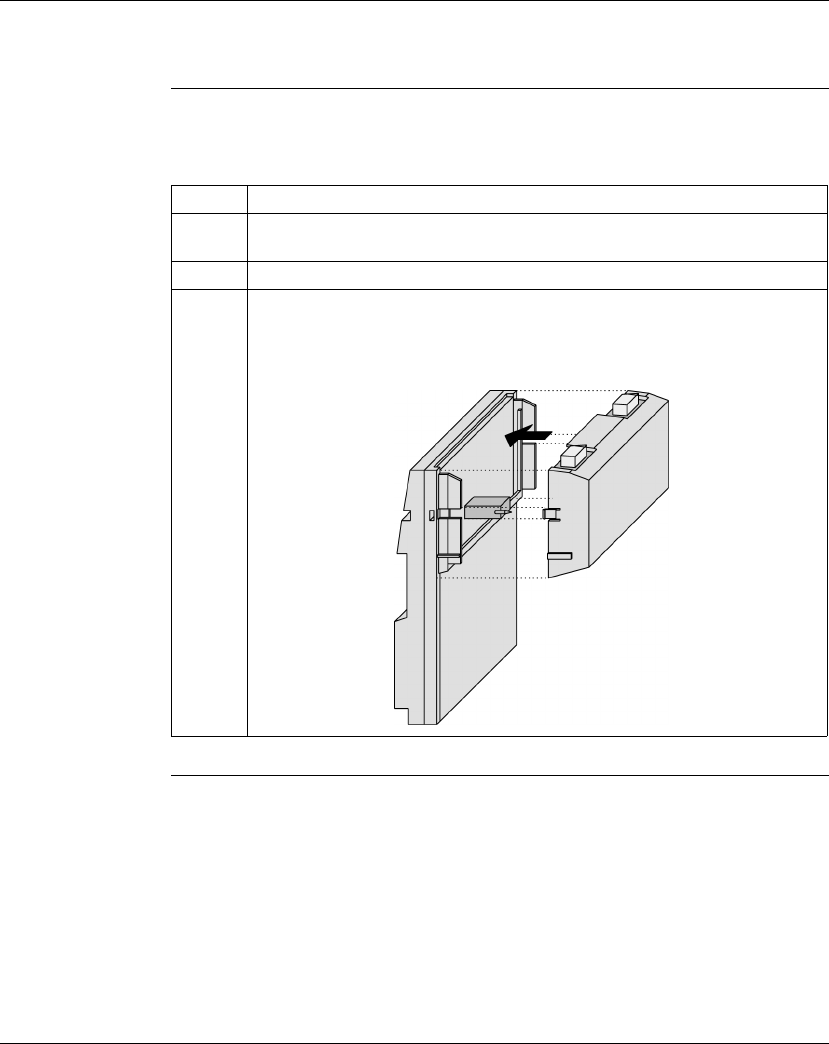
Assembling Momentum Components
90 870 USE 101 10 V.2
Assembling a Processor Adapter and I/O Base, Continued
Procedure:
Assembling a
Processor
Adapter and an
I/O Base
Follow the steps in the table below to assemble a Processor Adapter and an I/O
base.
Continued on next page
Step Action
1Choose a clean environment to assemble the I/O base and adapter to protect the
circuitry from contamination.
2Be sure that the I/O base is not under power when you assemble the module.
3Align the two plastic snap extensions on the Processor Adapter with the slots on
the sides of the I/O base. The 12-pin connectors will automatically line up when
the units are in this position. The two devices should be oriented so their
communication ports are facing out, on the back side of the assembly.
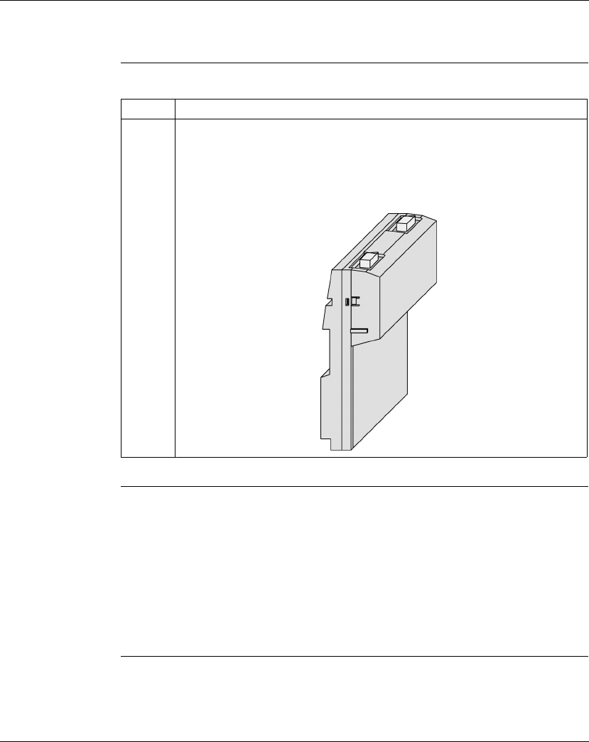
Assembling Momentum Components
870 USE 101 10 V.2 91
Assembling a Processor Adapter and I/O Base, Continued
Procedure:
Assembling a
Processor
Adapter and an
I/O Base,
Continued
Next Step Once the Processor Adapter has been assembled, it can be mounted on a DIN rail
or surface mounted inside a panel enclosure. A Momentum M1 CPU assembly is
classified as open equipment. Open equipment should be installed in an industry-
standard enclosure, and direct access must be restricted to qualified service
personnel.
For a detailed description of installation procedures and grounding considerations,
refer to the
Momentum I/O Bases User Manual
(870 USE 002 00).
Step Action
4Push the Processor Adapter onto the base, gently pressing the locking tabs
inward.
Result: The locking tabs on each side of the Processor Adapter slide inside the
I/O base and out through the locking slot. The 12-pin connectors on the two units
are mated to each other in the process.
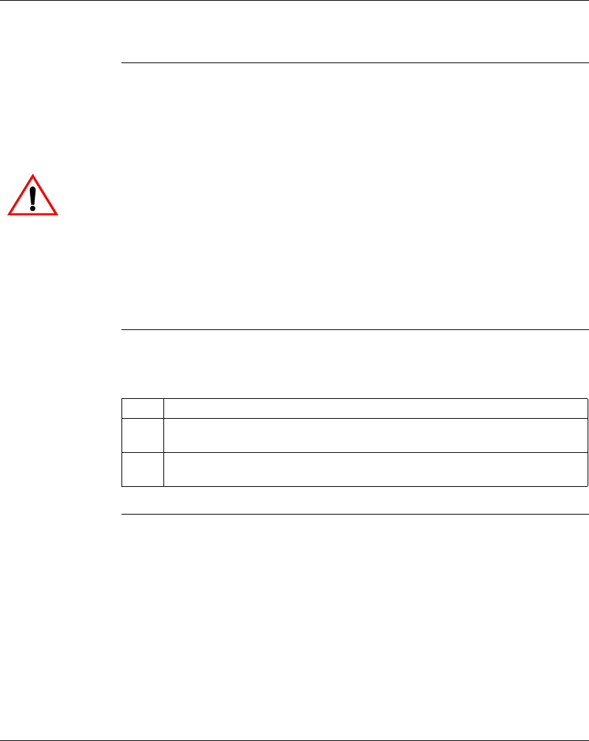
Assembling Momentum Components
92 870 USE 101 10 V.2
Disassembling a Processor Adapter from an I/O Base
Overview This section contains safety precautions and a procedure for disassembling a
Processor Adapter from an I/O base.
Tools Required A flat-head screw driver.
Procedure:
Disassembling
an Adapter from
an I/O Base
Follow the steps in the table below to remove a Processor Adapter from an I/O
base.
Continued on next page
CAUTION
ELECTRICAL CIRCUITRY MAY BE EXPOSED
Before removing an adapter from the base, disconnect the wiring connectors. Be sure that
the I/O base is not under power when it does not have a Momentum adapter mounted on it.
Failure to observe this precaution can result in injury or equipment damage and will
void the product warranty.
Step Action
1Choose a clean environment to disassemble the unit, in order to protect the
circuitry from contamination.
2Be sure that the I/O base is not under power, by removing the terminal connectors
from the I/O base.
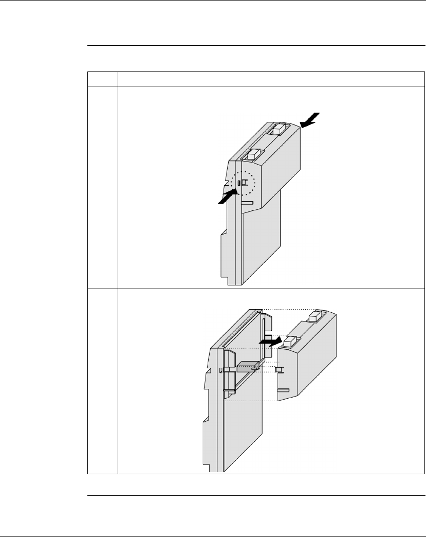
Assembling Momentum Components
870 USE 101 10 V.2 93
Disassembling a Processor Adapter from an I/O Base, Continued
Procedure:
Disassembling
an Adapter from
an I/O Base,
Continued
Step Action
3Use a screwdriver to push the clips on both sides of the Processor Adapter inward,
as shown in the illustration below.
4Lift adapter straight up and away from base, maintaining pressure on clips.

Assembling Momentum Components
94 870 USE 101 10 V.2
Section 3.2
Assembling a CPU with an Option Adapter
Overview
Purpose An Option Adapter can only be used in conjunction with a Processor Adapter. It
cannot be used alone with an I/O base.
This section describes how to add an Option Adapter when assembling a
Momentum module and how to remove an Option Adapter from the assembled
module.
In This Section This section contains the following topics:
For This Topic... See Page...
Assembling a Processor Adapter and an Option Adapter 95
Mounting the Assembled Adapters on the I/O Base 98
Disassembling a Module with an Option Adapter 101

Assembling Momentum Components
870 USE 101 10 V.2 95
Assembling a Processor Adapter and an Option Adapter
Overview If a Momentum Option Adapter is used, it is mounted between a Momentum M1
Processor Adapter and a Momentum I/O base in a three-tiered stack.
This section contains guidelines, safety precautions and a procedure for
assembling a Processor Adapter and an Option Adapter.
The next section describes how to mount the assembled adapters on an I/O base.
Guidelines We recommend that you snap the Option Adapter and the M1 Processor Adapter
together before mounting them on the I/O base.
Connection
Points Between
Adapters
The Option Adapter and M1Processor connect at these four points:
lThe plastic snap extensions on the two sides of the M1 fit into the two slots on
the sides of the Option Adapter
lThe 12-pin connectors on the center of the back walls of the two units mate
together
lThe 34-pin processor extension connectors that run along the left sidewalls of
the components mate together
No Tools
Required The components can be snapped together by hand; no assembly tools are
required. A flat-head screw driver is required to disassemble the unit.
Continued on next page
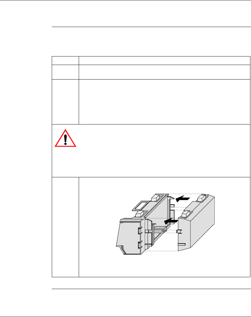
Assembling Momentum Components
96 870 USE 101 10 V.2
Assembling a Processor Adapter and an Option Adapter, Continued
Procedure:
Assembling an
Option Adapter
and Processor
Follow the steps in the table below to assemble an option adapter and an M1
processor.
Continued on next page
Step Action
1Choose a clean environment to assemble the Option Adapter and processor to
protect the circuitry from contamination.
2Align the two plastic snap extensions on the sides of the M1 Processor Adapter
with the slots on the sides of the Option Adapter.
The 12-pin connectors and processor extension connectors will automatically
line up when the units are in this position. The two devices should be oriented
so that their communication ports are facing out on the back side of the
assembly.
CAUTION
PIN ALIGNMENT
Proper assembly requires that the 34 pins on the processor extension
connector be aligned correctly with the mating socket on the M1 processor
adapter. Do not connect one side and try to rotate the M1 onto the option
adapter.
Failure to observe this precaution can result in equipment damage.
3Push the Processor Adapter onto the Option Adapter, gently pressing the
locking tabs inward.
Result: The locking tabs on each side of the Processor Adapter slide inside
the Option Adapter and out through the locking slot. The 12-pin and 34-pin
connectors on the two units are mated to each other in the process.

Assembling Momentum Components
870 USE 101 10 V.2 97
Assembling a Processor Adapter and an Option Adapter, Continued
Next Step Follow the directions in the next section to mount the assembled adapters on the
I/O base.

Assembling Momentum Components
98 870 USE 101 10 V.2
Mounting the Assembled Adapters on the I/O Base
Overview This section gives guidelines, safety precautions and a procedure for mounting the
assembled Processor and Option Adapter on an I/O base.
Guidelines The assembled adapters connect with the I/O base at these seven points:
lTwo plastic snaps on the front of the Option Adapter fit into two slots on the
front of the I/O base
lThe plastic snap extensions on the two sides of the Option Adapter fit into the
two slots on the sides of the I/O base
lThe 12-pin connectors on the center of the back walls of the two units mate
together
lThe plastic stirrup on the back of the Option Adapter clips onto the bottom of
the I/O base
Continued on next page
CAUTION
ELECTRICAL CIRCUITRY MAY BE EXPOSED
Electrical circuitry on the I/O base may be exposed when an adapter is not mounted. Be
sure that the I/O base is not under power whenever it does not have a Momentum adapter
mounted on it.
To be sure that power is not present, do not insert the wiring connectors to the I/O base until
after the adapter has been mounted. When more than one connector is on the I/O base,
remove all connectors to prevent the unit from receiving power from an unexpected source.
Failure to observe this precaution can result in injury or equipment damage and will
void the product warranty.
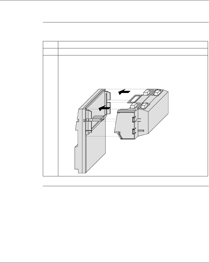
Assembling Momentum Components
870 USE 101 10 V.2 99
Mounting the Assembled Adapters on the I/O Base, Continued
Procedure:
Mounting the
Assembled
Adapters on an
I/O Base
Follow the steps in the table below to mount the assembly on an I/O base.
Continued on next page
Step Action
1Be sure that the I/O base is not under power when you assemble the module.
2Align the four plastic snap extensions, on the front and sides of the Option Adapter,
with the slots on the I/O base.
The 12-pin connectors will automatically line up when the units are in this position.
The devices should be oriented so their communication ports are facing out on the
back side of the assembly.
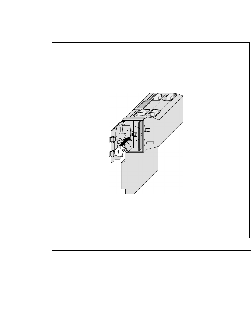
Assembling Momentum Components
100 870 USE 101 10 V.2
Mounting the Assembled Adapters on the I/O Base, Continued
Procedure:
Mounting the
Assembled
Adapters on an
I/O Base,
Continued
Step Action
3Push the assembled adapters onto the base, gently pressing the locking tabs
inward.
Snap #1 shown in the illustration below will not align properly with the mating slot in
the I/O base unless the Option Adapter is placed straight onto the base. Do not
attach just one latch and rotate the Option Adapter onto the I/O base.
Result: The locking tabs on each side of the Option Adapter slide inside the I/O
base and out through the locking slot. The 12-pin connectors on the two units are
mated to each other in the process.
4Apply slight pressure to the top of the stirrup on the back of the Option Adapter so
that it snaps into place on the bottom of the I/O base.

Assembling Momentum Components
870 USE 101 10 V.2 101
Disassembling a Module with an Option Adapter
Overview The three-tiered assembly is designed to fit together tightly, so it can withstand
shock and vibration in an operating environment. This section contains two
procedures:
lRemoving the assembled adapters from the I/O base
lRemoving the Option Adapter from the Processor
Tools Required Flat-head screwdriver.
Continued on next page
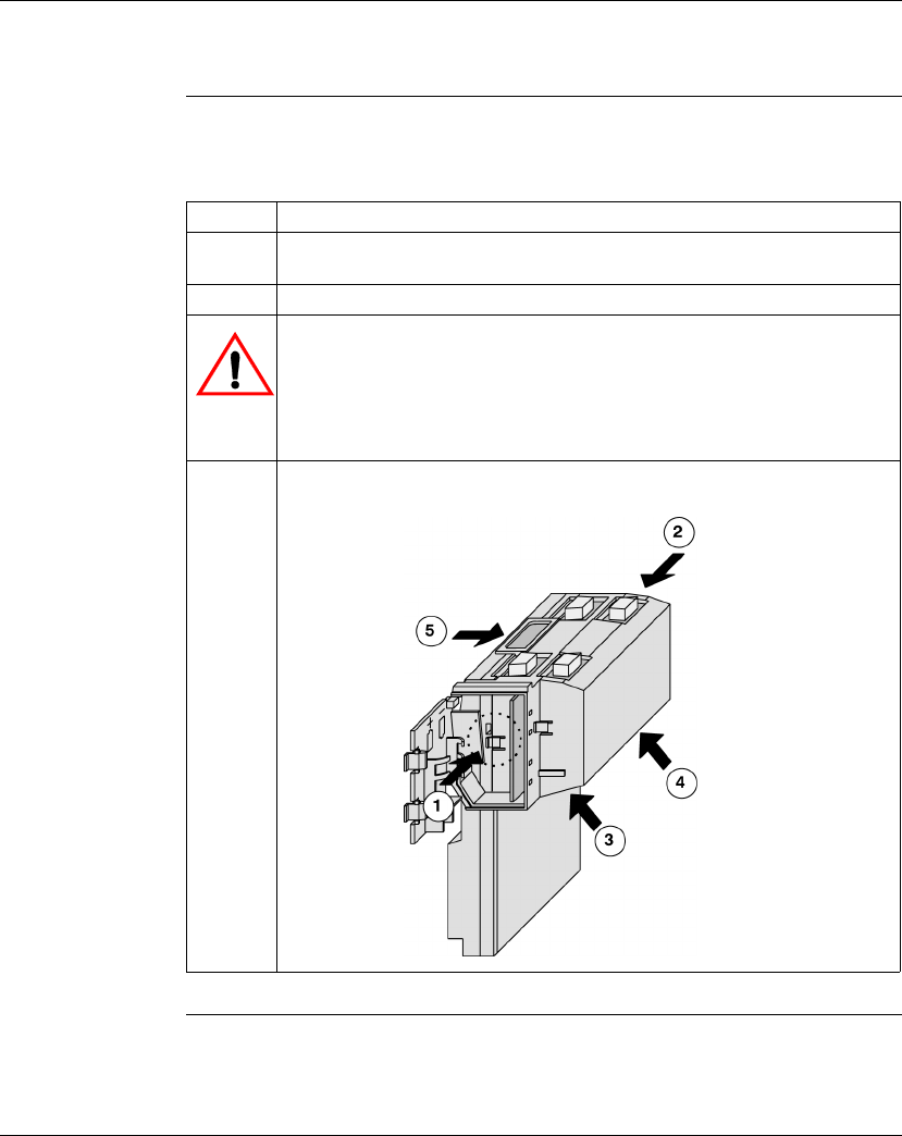
Assembling Momentum Components
102 870 USE 101 10 V.2
Disassembling a Module with an Option Adapter, Continued
Procedure:
Removing the
Adapter
Assembly from
the I/O Base
Follow the steps in the table below to remove the assembled Option Adapter and
M1 Processor Adapter from the I/O base.
Continued on next page
Step Action
1Be sure that the power is off by removing the terminal connectors from the
I/O base.
2Remove the assembled unit from its wall or DIN rail mounting surface.
CAUTION
EXPOSED CIRCUITRY IN BATTERY COMPARTMENT
Use care when you insert a screwdriver in the battery compartment so that you
do not scratch any exposed elements.
Failure to observe this precaution can result in equipment damage.
3Open the battery door and use a flat-head screwdriver to release snaps 1 and 2
as shown in the illustration below.
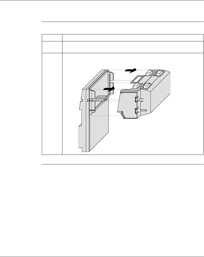
Assembling Momentum Components
870 USE 101 10 V.2 103
Disassembling a Module with an Option Adapter, Continued
Procedure:
Removing the
Adapter
Assembly from
the I/O Base,
Continued
Continued on next page
Step Action
4Once snaps 1 and 2 have been disengaged, use the screwdriver to release
snaps 3 and 4 on the front of the assembly.
5Gently lift the stirrup on the back of the Option Adapter with your fingers until it
disengages from the bottom of the I/O base. Then lift the Option Adapter and
M1 assembly from the I/O base.
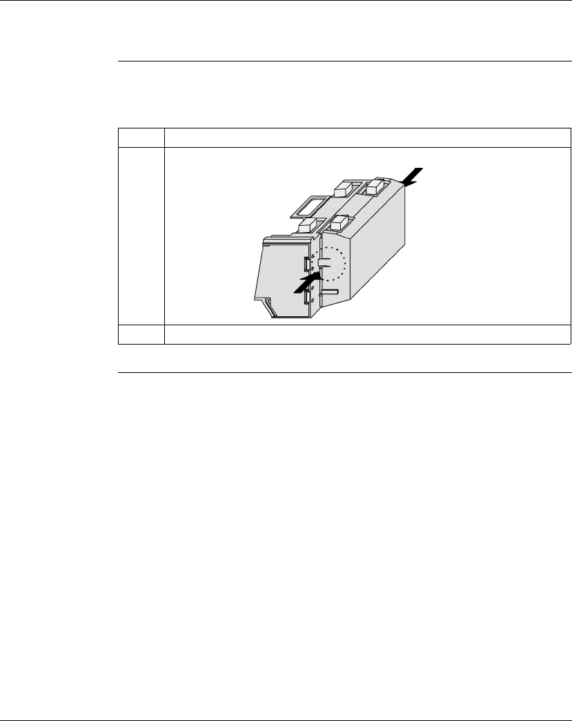
Assembling Momentum Components
104 870 USE 101 10 V.2
Disassembling a Module with an Option Adapter, Continued
Procedure:
Disassembling
an Option
Adapter and M1
Processor
Follow the steps in the table below to remove the Option Adapter from the M1
processor.
Step Action
1Use a screwdriver to push the clips on both sides of the adapter inward.
2Lift off the adapter.
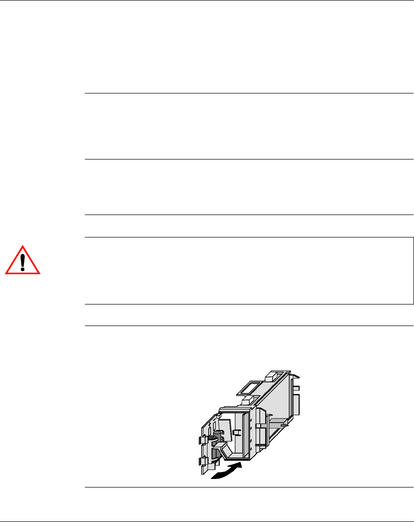
Assembling Momentum Components
870 USE 101 10 V.2 105
Section 3.3
Installing Batteries in an Option Adapter
Installation Guidelines
Why Install
Batteries? If you are using a Momentum Option Adapter in your CPU assembly, you have a
battery-backup capability. The batteries will maintain user logic, state RAM values
and the time-of-day clock in the event that the CPU loses power.
What Kind of
Batteries? Two AAA alkaline batteries can be installed in the compartment on the side of the
Option Adapter. A set of batteries is supplied with the module (not installed).
Installing
Batteries When installing the batteries, observe correct polarity, as indicated on the
compartment door.
Continued on next page
CAUTION
ELECTRONIC CIRCUITRY EXPOSED
When the battery door is open, electronic circuitry is exposed. Follow proper ESD measures
while handling the equipment during battery maintenance.
Failure to observe this precaution can result in injury or equipment damage.
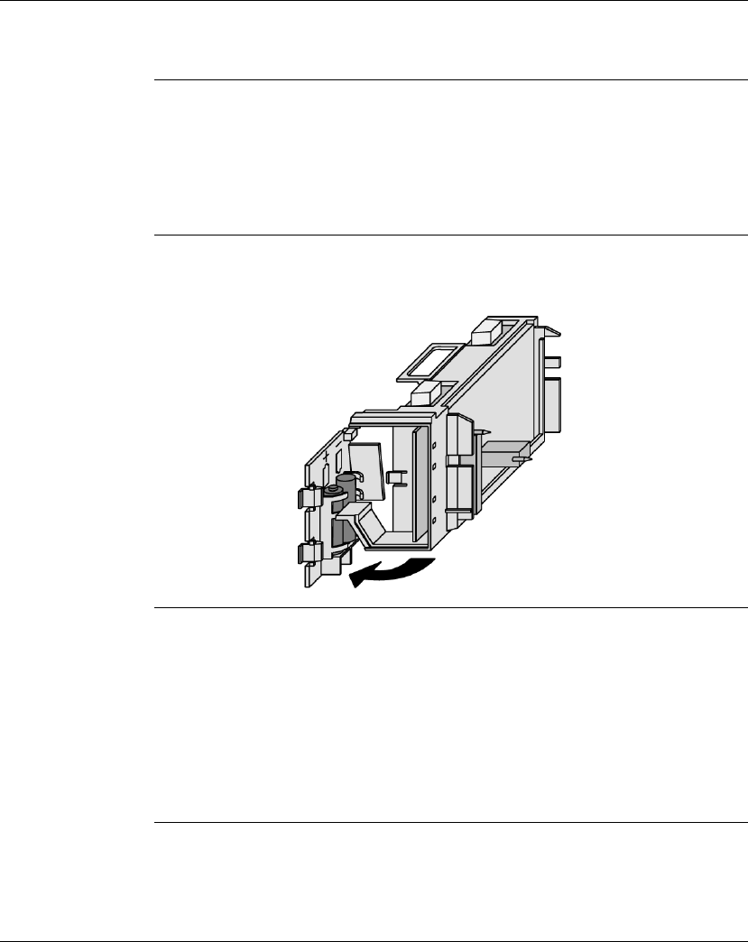
Assembling Momentum Components
106 870 USE 101 10 V.2
Installation Guidelines, Continued
Leave Power On
When Changing
Batteries
Once your CPU has been commissioned and is running, maintain power to the
module whenever you change the batteries.
Unless you save to flash, if you change the batteries while the power is OFF, you
will have to reload your user logic program from the original files.
Removing and
Replacing
Batteries
Battery maintenance should be performed only by qualified personnel according to
the following illustration.
Monitor the
Battery Because a Momentum CPU assembly is designed to be installed in a cabinet
where it cannot be seen at all times, no LED was created to monitor battery health.
We recommend that you reserve a battery coil in your programming panel software
configuration and use it to monitor the health of your battery and report the need for
replacement prior to battery failure (refer to
Reserving and Monitoring a Battery
Coil
on page 224 for Modsoft or
Reserving and Monitoring a Battery Coil
on page
328 for Concept).

Assembling Momentum Components
870 USE 101 10 V.2 107
Section 3.4
Labeling the CPU
Guidelines for Labeling the CPU
Overview A fill-in label is shipped with each I/O base. This label should be placed on the M1
Processor Adapter that you mount on that base.
This section describes the label and provides an illustrated example.
Fill-In Label A completed label provides information about the assembled module and its I/O
field devices that can be used by service and maintenance personnel.
The model number of the I/O base is marked on the fill-in label directly above the
color code. The cutout area above the I/O model number allows the model number
of the adapter to show through.
Continued on next page
Note: An Option Adapter may also be used in the assembled module. You will
find its model number printed in the upper left corner of Option Adapter
housing.
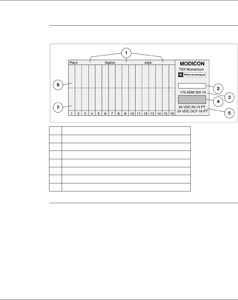
Assembling Momentum Components
108 870 USE 101 10 V.2
Guidelines for Labeling the CPU, Continued
Example of a
Fill-In Label A fill-in label is illustrated below.
No. Description
1 Fields for plant name, station name and network address
2Cutout–the model number of the adapter shows through
3 Model Number of the I/O base
4 Color code of the I/O base
5 Short description of the I/O base
6 Field for the symbol name of inputs
7 Field for the symbol name of outputs

870 USE 101 10 V.2 109
Communication Ports
At a Glance
Purpose This part describes the communication ports available with TSX Momentum
Processor Adapters and Option Adapters.
In This Part This part contains the following chapters:
For Information On... See Chapter... On Page...
Using the Modbus Ports 4 111
Using the Ethernet Port 5 141
Using the I/OBus Port 6 171
Using the Modbus Plus Ports 7 181

Communication Ports
110 870 USE 101 10 V.2

870 USE 101 10 V.2 111
Using the Modbus Ports
At a Glance
Purpose This chapter describes Modbus Port 1 and Modbus Port 2, including
communication parameters, cabling guidelines for Modbus RS485 networks, cable
accessories and pinouts.
In This Chapter This chapter contains the following sections:
For This Topic... See Section... On Page...
Modbus Port 1 1 112
Modbus Port 2 2 119

Using the Modbus Ports
112 870 USE 101 10 V.2
Section 4.1
Modbus Port 1
Overview
Purpose Modbus Port 1 is standard on all Momentum M1 Processor Adapters, except the
171 CCC 960 20 and 171 CCC 980 20, 171 CCC 960 30 and 171 CCC 980 30
ethernet adapters. This section describes the port and recommended cable
accessories, and provides pinouts.
In This Section This section contains the following topics:
For This Topic... See Page...
Modbus Port 1 113
Cable Accessories for Modbus Port 1 116
Pinouts for Modbus Port 1 117
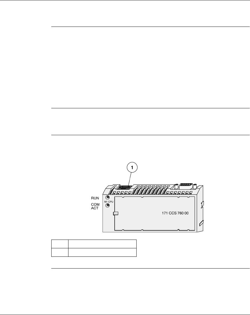
Using the Modbus Ports
870 USE 101 10 V.2 113
Modbus Port 1
Introduction Modbus Port 1 is an RS232 asynchronous serial port that permits a host computer
to communicate to the CPU for:
lProgramming
lData transfer
lUpload/download
lOther host operations
This section describes the port.
Connector Type The Modbus Port 1 connector is a female RJ45 phone jack.
Illustration The following illustration shows the position of Modbus Port 1 on a Processor
Adapter:
Continued on next page
Label Description
1 Modbus Port 1

Using the Modbus Ports
114 870 USE 101 10 V.2
Modbus Port 1, Continued
Port Parameters Modbus Port 1 supports the following communication parameters.
Continued on next page
Baud 50 1800
75 2000
110 2400
134 3600
150 4800
300 7200
600 9600
1200 19,200
Parity EVEN
ODD
NONE
Mode/Data Bits 7-bit ASCII
8-bit RTU
Stop Bit 1
Modbus Address In the range 1 ... 247

Using the Modbus Ports
870 USE 101 10 V.2 115
Modbus Port 1, Continued
Default
Parameters The factory-set default communication parameters for Modbus Port 1 are:
l9600 baud
lEVEN parity
l8-bit RTU mode
l1 stop bit
lModbus address
A Processor Adapter cannot support more than one stop bit. If you change this
default setting in the configuration software, the Processor Adapter will ignore the
change.
All other port parameters can be successfully modified in the configuration
software.
Auto-Logout
Feature If a programming panel is logged into the CPU via the RS232 serial port and its
cable gets disconnected, the CPU automatically logs out the port. This auto-logout
feature is designed to prevent a lock-up situation that could prevent other host
stations from logging in on other ports.

Using the Modbus Ports
116 870 USE 101 10 V.2
Cable Accessories for Modbus Port 1
Overview This section describes the cable and D-shell adapters needed to connect Modbus
Port 1 to a programming station. It also provides pinouts for the adapters.
Cables The cable connecting a programming station to the CPU (via Modbus Port 1) can
be up to 9.5m long. Three premade cable assemblies are available from Schneider
Electric:
All three assemblies are standard eight-position, foil-shielded, flat telephone cables
with male RJ45 connectors on each end. One RJ45 connector plugs into Modbus
Port 1 on the CPU, and the other plugs into a female D-shell adapter that fits onto
the programming station.
D-Shell Adapters Two D-shell adapters are available from Schneider Automation for CPU-to-
computer connections:
lA 110 XCA 203 00 9-pin adapter for 9 pin serial ports
lA 110 XCA 204 00 25-pin adapter for 25 pin serial ports
These adapters have an RJ45 jack on one end that allows them to clip directly onto
a cable assembly.
Length Part Number
1 m (3 ft.) 110 XCA 282 01
3 m (10 ft.) 110 XCA 282 02
6 m (20 ft.) 110 XCA 282 03
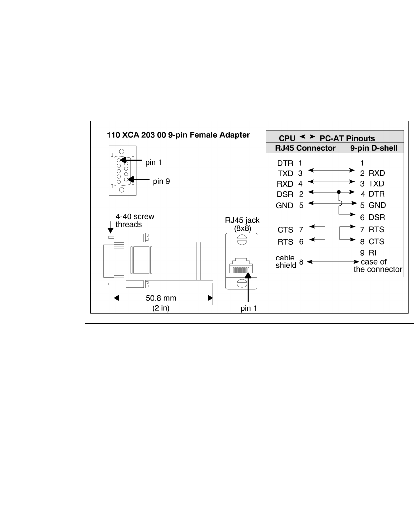
Using the Modbus Ports
870 USE 101 10 V.2 117
Pinouts for Modbus Port 1
Overview This section provides pinouts for the D-shell adapters for Modbus Port 1.
110 XCA 203 00
Pinout The pinout for this adapter is shown in the illustration below:
Continued on next page
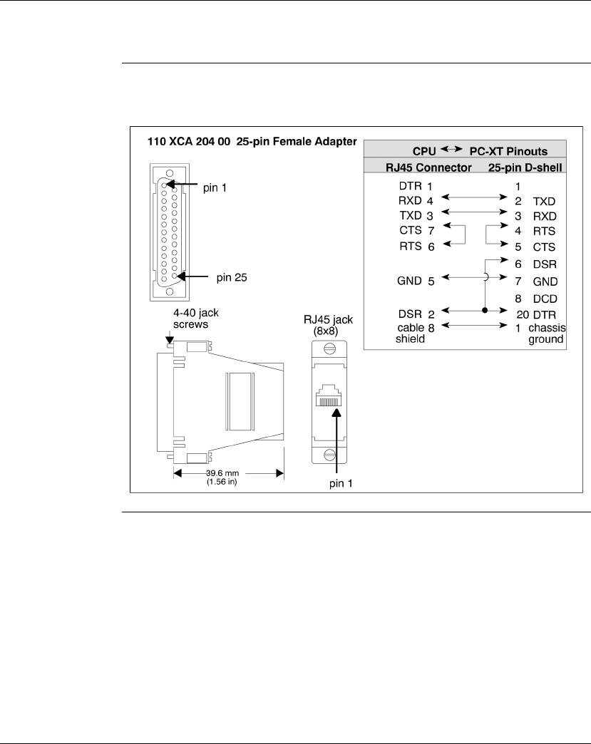
Using the Modbus Ports
118 870 USE 101 10 V.2
Pinouts for Modbus Port 1, Continued
110 XCA 204 00
Pinout The pinout for this adapter is shown in the illustration below:

Using the Modbus Ports
870 USE 101 10 V.2 119
Section 4.2
Modbus Port 2
Overview
Purpose Five Momentum components offer this port:
l171 CCS 780 00 Processor Adapter
l171 CCC 780 10 Processor Adapter
l171 CCC 980 20 Processor Adapter
l171 CCC 980 30 Processor Adapter
l172 JNN 210 32 Serial Option Adapter
This section describes the port and provides guidelines for Modbus RS485
networks.
In This Section This section contains the following topics:
Topics Page
Modbus Port 2 120
Four-Wire Cabling Schemes for Modbus RS485 Networks 123
Two-Wire Cabling Schemes for Modbus RS485 Networks 126
Cable for Modbus RS485 Networks 129
Connectors for Modbus RS485 Networks 132
Terminating Devices for Modbus RS485 Networks 134
Pinouts for Modbus RS485 Networks 135

Using the Modbus Ports
120 870 USE 101 10 V.2
Modbus Port 2
Two Types of
Port Modbus Port 2 is available in two types:
Features of an
RS485 Port Modbus Port 2 can be configured as an RS485 port. RS485 supports two-wire or
four-wire cabling. A multimaster/slave system must use two-wire cabling. A single
master/slave system may use two- or four-wire cabling.
The RS485 protocol handles messaging over long distances with higher level of
noise immunity than RS232 without the need for modems.
Limit of Two
Modbus Ports The Momentum M1 Processor Adapters can support a maximum of two Modbus
ports.
If a 172JNN 210 32 Serial Option Adapter is used in conjunction with a
171 CCS 780 00 or 171 CCC 780 10 Processor Adapter, the RS485 port on the
Processor Adapter becomes Modbus Port 2. The port on the Option Adapter
becomes electrically neutral and does not support any communication activities.
(The TOD clock and battery backup system on the Option Adapter continue to
work.)
Continued on next page
Component Type of Port Type of Connector
171 CCS 780 00
171 CCC 780 10
171 CCC 980 20
171 CCC 980 30
Processor Adapters
Built-in, dedicated RS485
port
9-pin D-shell connector
172 JNN 210 32
Serial Option Adapter
User may configure port as
RS232 or RS485*
RJ45 phone jack connector
*If the Option Adapter is combined with the 171 CCS 780 00, or 171 CCC 780 10,
171 CCC 980 20 or 171 CCC 980 30 Processor Adapter, the Modbus port on the Option
Adapter will be disabled.

Using the Modbus Ports
870 USE 101 10 V.2 121
Modbus Port 2, Continued
Port Parameters Modbus Port 2 offers the following communication parameters:
Continued on next page
Baud 50 1800
75 2000
110 2400
134 3600
150 4800
300 7200
600 9600
1200 19,200
Parity EVEN
ODD
NONE
Mode/Data Bits 8-bit RTU
7-bit ASCII
Stop Bit 1
Modbus Address In the range 1 ... 247
Comm Protocol RS232
RS485

Using the Modbus Ports
122 870 USE 101 10 V.2
Modbus Port 2, Continued
Default
Parameters The factory-set default communication parameters for Modbus Port 2 are:
l9600 baud
lEVEN parity
l8-bit RTU mode
l1 stop bit
lModbus network address 1
lRS232 protocol
Auto-Logout
Feature Only
with RS232
If the Serial Option Adapter is used and the RS232 port is chosen, auto-logout is
supported. If a programming panel is logged into the CPU via the serial port and its
cable gets disconnected, the Processor Adapter automatically logs out the port.
This auto-logout feature is designed to prevent a lock-up situation that could
prevent other host stations from logging in on other ports.
Auto-logout is not available for any RS485 port, including the RS485 option on the
Serial Option Adapter. The user must log out of the processor using the
programming software.
Note: Processor Adapters support only one stop bit. If you change this default
setting in the configuration software, the Processor Adapter will ignore the
change.
Note: The default protocol must be changed from RS232 to RS485 for the
171 CCS 780 00,171 CCC 780 10 Processor Adapters or the port will not
function. The 171 CCC 980 20 and 171 CCC 980 30 change
automatically.

Using the Modbus Ports
870 USE 101 10 V.2 123
Four-Wire Cabling Schemes for Modbus RS485 Networks
Introduction Four-wire cabling schemes may be used for single master/slave communications.
Only one master is allowed. The master may be located anywhere in the network.
Length The maximum length of cable from one end of network to other is 2000 ft. (609 m).
Number of
Devices The maximum number of devices in a network is 64 if all are Momentum devices.
Otherwise, the maximum is 32.
Termination You must terminate both ends of the cable run with special terminating resistors.
Master Cable The master of this master/slave cabling scheme must be connected on at least one
side to a master cable, a special cable that crosses the transmit and receive lines.
The other side may be connected to a master cable, or, if the master is at one end
of the cable run, a terminating resistor.
Continued on next page
Description Part Number
Modbus Plus or Modbus RS485 Terminating RJ45 Resistor Plugs
(pack of 2).
Color code - red
170 XTS 021 00
Description Part Number
Modbus RS485 (RJ45/RJ45) Master Communication Cable 170 MCI 041 10
Modbus Plus or Modbus RS485 Terminating RJ45 Resistor Plugs
(pack of 2).
Color code - blue
170 XTS 021 00
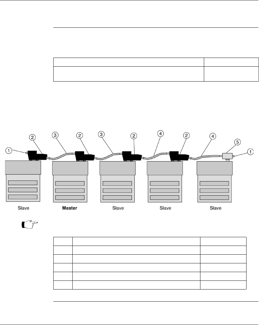
Using the Modbus Ports
124 870 USE 101 10 V.2
Four-Wire Cabling Schemes for Modbus RS485 Networks, Continued
Slave Cabling The slaves use a pin-for-pin cable, such as the Modbus Plus / Modbus RS485
Short Interconnect Cable or any Cat. 5 4-Twisted Pair Ethernet cable AWG#24.
Single Master/
Slave Option 1 The following illustration shows components used in a four-wire single master/slave
cabling scheme. In this view, a master cable (#3) is used on both sides of the
master. Each Momentum module must include a Processor Adapter or Option
Adapter with a Modbus RS485 port.
Continued on next page
Description Part Number
Modbus Plus / Modbus RS485 Short Interconnect Cable.
Color code - black
170 MCI 020 10
Note: Each cable has different colored boots. The color of the boots signifies the
cable’s function.
Label Description Part Number
1 Terminating resistor plug 170 XTS 021 00
2Modbus RS485 connector “T” (DB9 base) 170 XTS 040 00
3 Modbus RS485 Master Communication Cable 170 MCI 041 10
4 Modbus Plus / Modbus RS485 Short Interconnect Cable 170 MCI 020 10
5 Modbus RS485 connector “T” (RJ45 base) 170 XTS 041 00
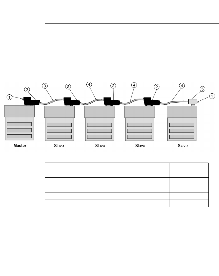
Using the Modbus Ports
870 USE 101 10 V.2 125
Four-Wire Cabling Schemes for Modbus RS485 Networks, Continued
Single Master/
Slave Option 2 The following illustration shows components used in a four-wire single master/slave
cabling scheme. In this view, the master is at one end of the network and is
connected by a single master cable (#3). Terminating resistors (#1) are used at
both ends of the network.
Each Momentum module must include a Processor Adapter or Option Adapter with
a Modbus RS485 port.
Label Description Part Number
1 Terminating resistor plug 170 XTS 021 00
2Modbus RS485 connector “T” (DB9 base) 170 XTS 040 00
3 Modbus RS485 Master Communication Cable 170 MCI 041 10
4 Modbus Plus / Modbus RS485 Short Interconnect Cable 170 MCI 020 10
5 Modbus RS485 connector “T” (RJ45 base) 170 XTS 041 00

Using the Modbus Ports
126 870 USE 101 10 V.2
Two-Wire Cabling Schemes for Modbus RS485 Networks
Introduction Two-wire cabling schemes may be used for single master/slave or multimaster/
slave communications. Masters may be located anywhere in the network.
Length The maximum length of cable from one end of network to other is 2000 ft. (609 m).
Number of
Devices The maximum number of devices in a network is 64 if all are Momentum devices.
Otherwise, the maximum is 32.
Termination One end of the cable run must be terminated with a terminating resistor (color code
is red).
The other end of the cable must be terminated with a terminating shunt, which
connects the transmit pair to the receiver pair (color code is blue).
Continued on next page
CAUTION
POTENTIAL FOR MULTIMASTER CONFLICTS
Configure a multimaster network carefully to avoid masters issuing simultaneous or
conflicting commands to the same slave module.
Failure to observe this precaution can result in injury or equipment damage.
Description Part Number
Modbus Plus or Modbus RS485 Terminating RJ45 Resistor Plugs
(pack of 2)
170 XTS 021 00
Modbus RS485 Terminating RJ45 Shunt Plugs 170 XTS 042 00
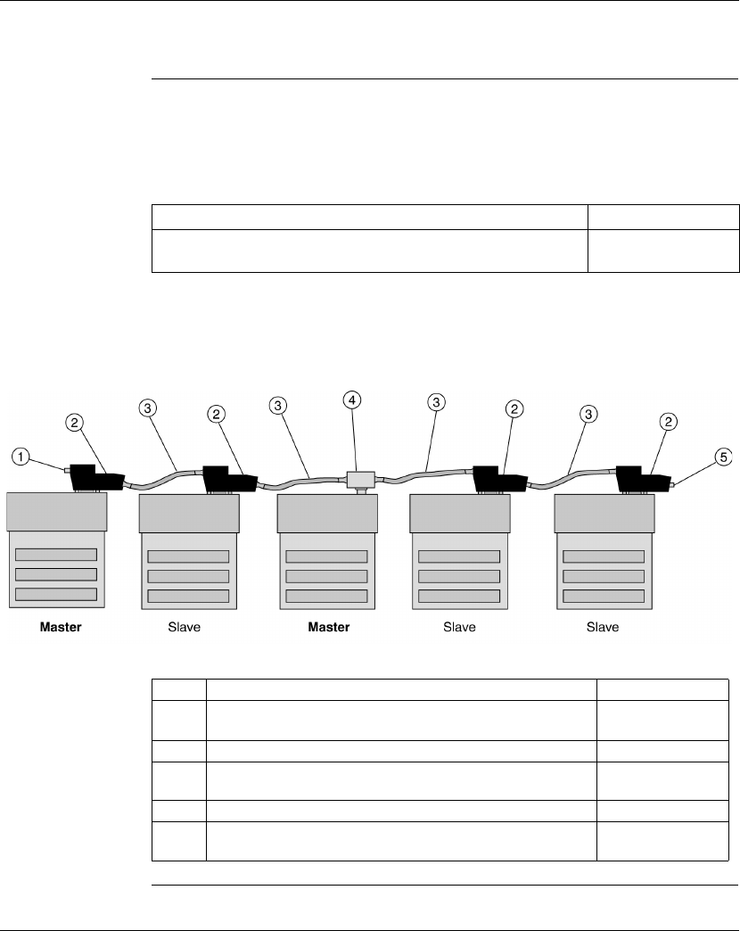
Using the Modbus Ports
870 USE 101 10 V.2 127
Two-Wire Cabling Schemes for Modbus RS485 Networks, Continued
Cable All devices are connected with the same pin-for-pin cable, such as the Modbus
Plus or Modbus RS485 Short Interconnect Cable or any Cat. 5 4-Twisted Pair
Ethernet cable AWG#24. A master/slave system using 2-wire cabling does not
require the special master communication cable.
Multimaster/
Slave Cabling The following illustration shows components used in a multimaster/slave network.
Each Momentum module must include a Processor Adapter or Option Adapter with
a Modbus RS485 port.
Continued on next page
Description Part Number
Modbus Plus or Modbus RS485 Short Interconnect Cable.
Color code - black
170 MCI 020 10
Label Description Part Number
1 Terminating resistor plug.
Color code - red
170 XTS 021 00
2Modbus RS485 connector “T” (DB9 base) 170 XTS 040 00
3 Modbus Plus / Modbus RS485 Short Interconnect Cable.
Color code - black
170 MCI 020 10
4 Modbus RS485 connector “T” (RJ45 base) 170 XTS 041 00
5 Terminating shunt plug.
Color code - blue
170 XTS 042 00
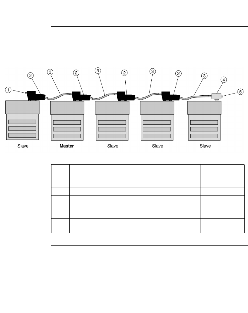
Using the Modbus Ports
128 870 USE 101 10 V.2
Two-Wire Cabling Schemes for Modbus RS485 Networks, Continued
Single Master/
Slave Cabling The following illustration shows components used for single master/slave
communications in a two-wire cabling scheme. Each Momentum module must
include a Processor Adapter or Option Adapter with a Modbus RS485 port.
Label Description Part Number
1 Terminating resistor plug.
Color code - red
170 XTS 021 00
2Modbus RS485 connector “T” (DB9 base) 170 XTS 040 00
3 Modbus Plus / Modbus RS485 Short Interconnect Cable.
Color code - black
170 MCI 020 10
4 Modbus RS485 connector “T” (RJ45 base) 170 XTS 041 00
5 Terminating shunt plug.
Color code - blue
170 XTS 042 00

Using the Modbus Ports
870 USE 101 10 V.2 129
Cable for Modbus RS485 Networks
Overview This section describes the cables which should be used in constructing an RS485
network for Momentum components.
Master
Communication
Cable
This cable is required for master/slave communications in a four-wire cabling
scheme. This cable is 10” long and has a
blue boot
.
Continued on next page
Description Part Number Illustration
Modbus RS485 (RJ45/RJ45)
Master Communication Cable
170 MCI 041 10

Using the Modbus Ports
130 870 USE 101 10 V.2
Cable for Modbus RS485 Networks, Continued
Interconnect
Cables Cable for connecting two Modbus RS485 devices, such as Momentum modules, is
available from Schneider Automation in four lengths. These cables have a
black
boot
.
Continued on next page
Description Part Number Illustration
Modbus Plus or Modbus RS485
Short Interconnect Cable (10”)
Can be used for Ethernet
170 MCI 020 10
Modbus Plus or Modbus RS485
3 ft. Interconnect Cable
Can be used for Ethernet
170 MCI 020 36
Modbus Plus or Modbus RS485
10 ft. Interconnect Cable
170 MCI 021 80
Modbus Plus or Modbus RS485
30 ft. Interconnect Cable
170 MCI 020 80

Using the Modbus Ports
870 USE 101 10 V.2 131
Cable for Modbus RS485 Networks, Continued
Other Premade
Cable Interconnect and Ethernet cable in various lengths and boot colors may be
obtained from other vendors, including Amp:
Custom Cable For custom cabling, use Cat. 5 4-Twisted Pair Ethernet Cable AWG#26. It may be
shielded or unshielded. Shielded cable is recommended for long runs and for noisy
environments. You may use stranded or unstranded cable. Keep in mind that
stranded cable is more flexible.
Custom Cable
Vendors Vendors include:
Crimping Tool Schneider Automation provides a crimping tool (490 NAB 000 10) and an RJ45 die
set (170 XTS 023 00) to attach the 170 XTS 022 00 connector to the cable.
Description Amp Part Number
2 ft. 621 894-2
5 ft. 621 894-4
7 ft. 621 894-5
10 ft. 621 894-6
14 ft. 621 894-7
Vendor Part # for Shielded Cable Part # for Unshielded Cable
Belden 1633A 1583A non plenum
1585A plenum
Berk/Tek 530131 540022
Alcatel Cable Net -- Hipernet Cat. 5 - UTP
(LSZH-rated cable)
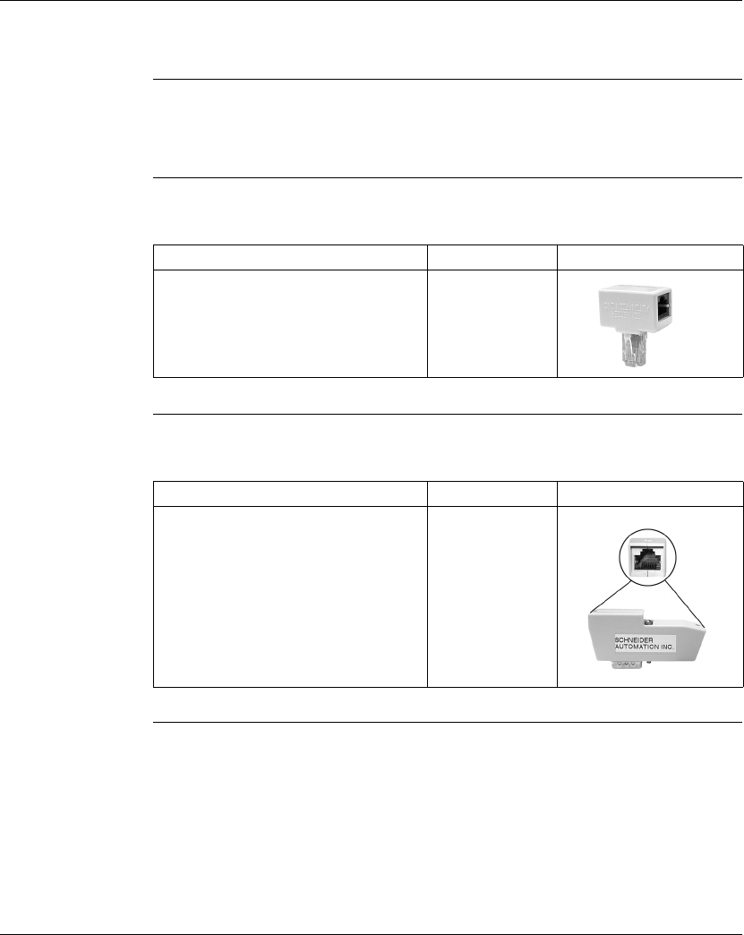
Using the Modbus Ports
132 870 USE 101 10 V.2
Connectors for Modbus RS485 Networks
Overview This section describes the connectors which should be used in constructing an
RS485 network for Momentum components.
RJ45 Connector
“T” This connector is used with the RS485 port on the 172 JNN 210 32 Option Adapter.
DB9 Connector
“T” This connector is used with the RS485 port on the Processor Adapters.
Continued on next page
Description Part Number Illustration
Modbus RS485 Connector “T”
(RJ45 base)
170 XTS 041 00
Description Part Number Illustration
Modbus RS485 Connector “T”
(DB9 base)
170 XTS 040 00

Using the Modbus Ports
870 USE 101 10 V.2 133
Connectors for Modbus RS485 Networks, Continued
Connectors for
Custom Cabling This RJ45 connector should be used when constructing custom cable for an RS485
network.
Description Part Number Illustration
RJ45 Connector (pack of 25) 170 XTS 022 00

Using the Modbus Ports
134 870 USE 101 10 V.2
Terminating Devices for Modbus RS485 Networks
Overview This section describes terminating devices which should be used in constructing
Modbus RS485 networks for Momentum devices.
Terminating
Resistor Plugs Terminating resistor plugs are used with the RS485 connector (RJ45 base) at the
last device on either end of a four-wire cable network or at one end of a two-wire
cable network.
Shunt Plugs Shunt plugs are used with the RS485 connector (RJ45 base) at one end of a two-
wire cable network. The plug is used at the last device on the network.
Description Part Number Illustration
Modbus Plus or Modbus RS485
Terminating RJ45 Resistor Plugs
(pack of 2).
Color code - red
170 XTS 021 00
Description Part Number Illustration
Modbus RS485 Terminating
RJ45 Shunt Plugs.
Color code - blue
170 XTS 042 00
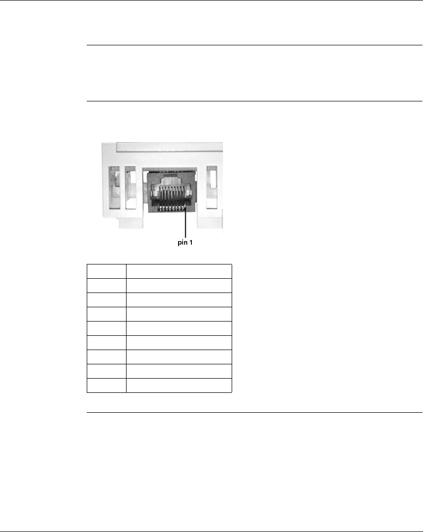
Using the Modbus Ports
870 USE 101 10 V.2 135
Pinouts for Modbus RS485 Networks
Overview This section contains pinouts for wiring an RS485 network for Momentum
components.
RJ45 Pinout The illustration below shows the pinouts for wiring an RJ45 connector for RS485:
Continued on next page
Pin Function
1RXD -
2RXD +
3 TXD +
4 Reserved
5 Signal common
6 TXD -
7 Reserved
8 Shield
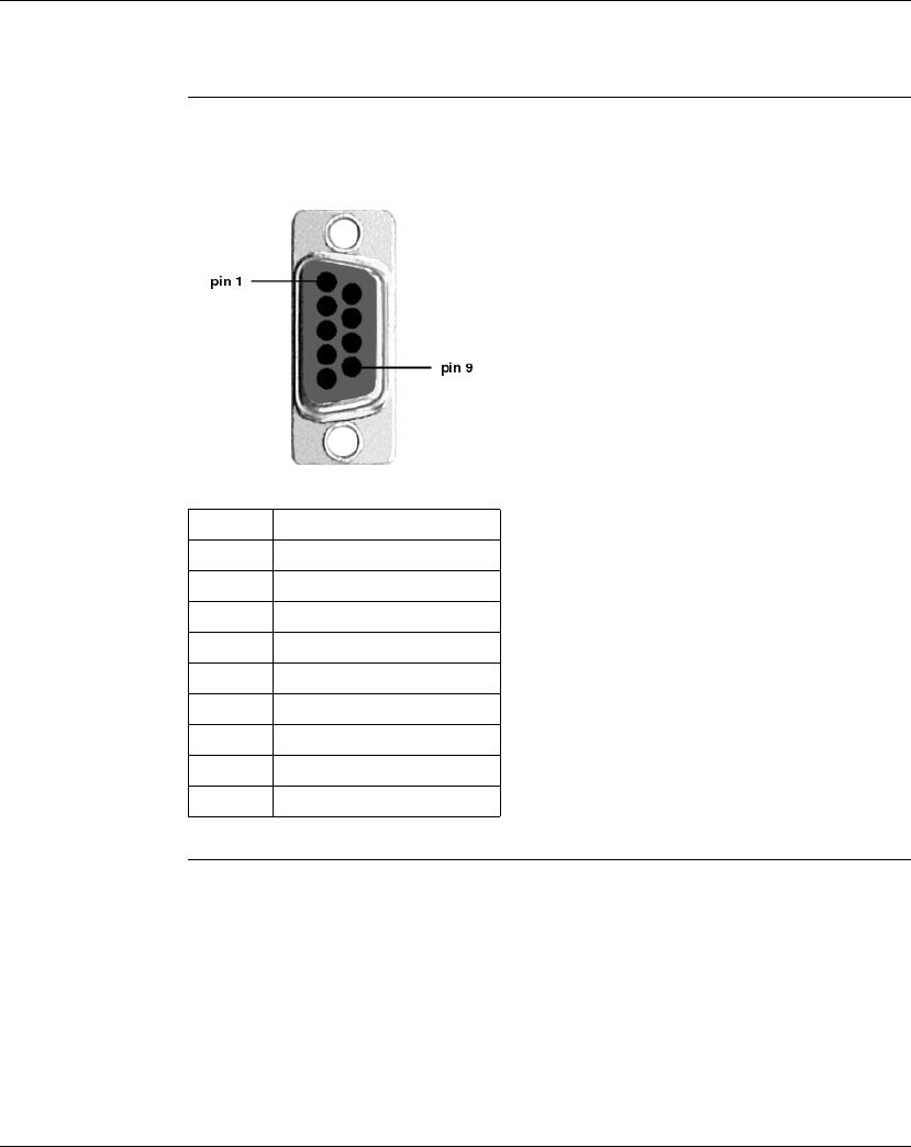
Using the Modbus Ports
136 870 USE 101 10 V.2
Pinouts for Modbus RS485 Networks, Continued
9-Pin D-Shell
Pinout The illustration below shows the pinouts for wiring a male 9-pin D-shell connector
for RS485. The metal shell is connected to chassis ground.
Continued on next page
Pin Function
1 TXD +
2RXD +
3 Signal common
4 Reserved
5 Reserved
6 TXD -
7RXD -
8 Reserved
9 Reserved
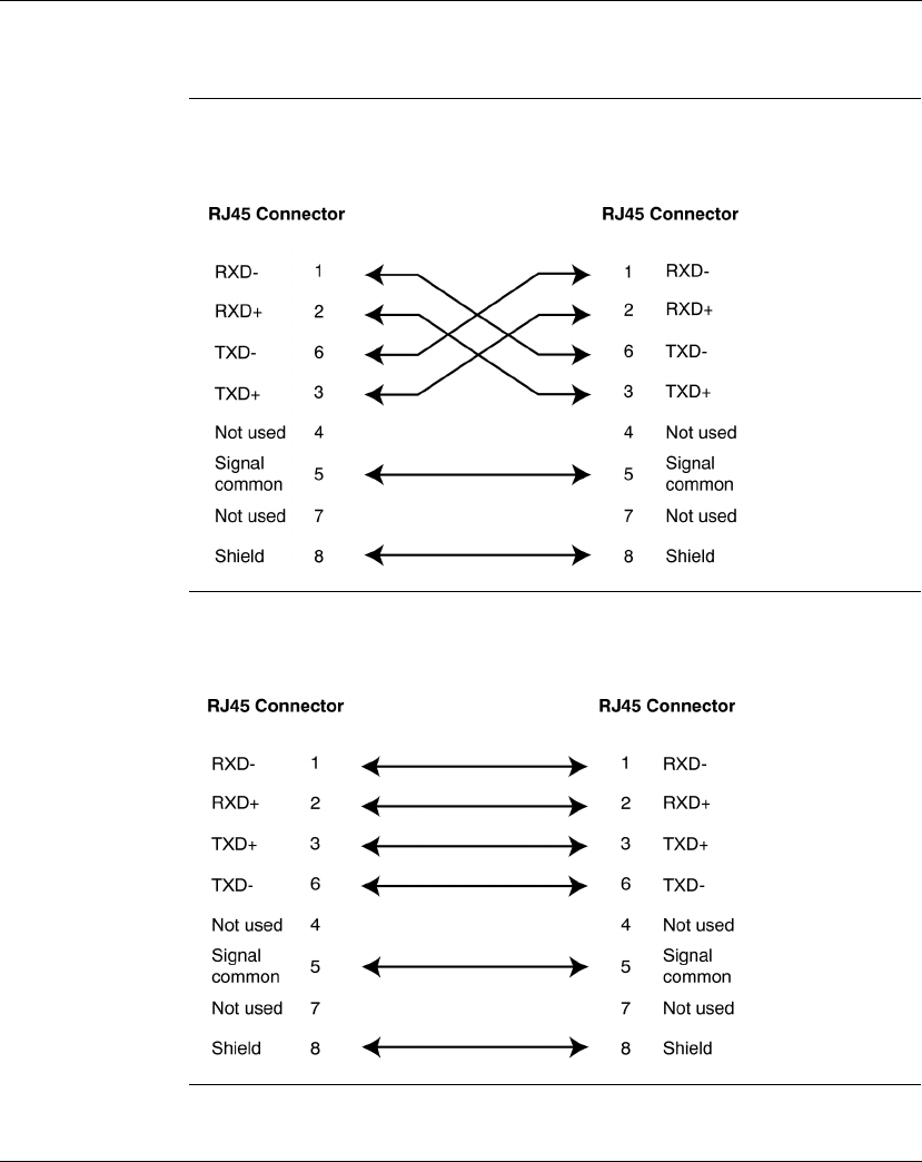
Using the Modbus Ports
870 USE 101 10 V.2 137
Pinouts for Modbus RS485 Networks, Continued
Master
Communication
Cable
The illustration below shows the pinout for the 170 MCI 041 10 Modbus RS485
(RJ45/RJ45) Master Communication Cable:
Interconnect
Cables The illustration below shows the pinout for the 170 MCI 02x xx Modbus Plus or
Modbus RS485 Interconnect Cables (10 in, 3 ft., 10 ft. and 30 ft.:
Continued on next page
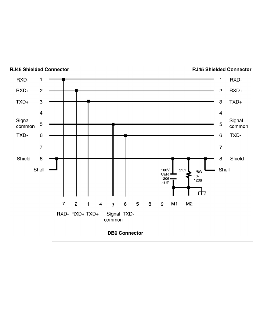
Using the Modbus Ports
138 870 USE 101 10 V.2
Pinouts for Modbus RS485 Networks, Continued
Modbus RS485
Connector “T”
(DB9 Base)
The illustration below shows the pinout for the Modbus RS485 Connector “T” (DB9
base):
Continued on next page
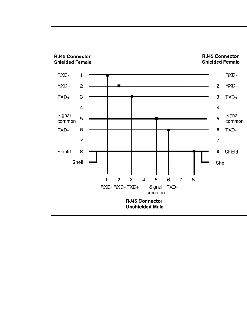
Using the Modbus Ports
870 USE 101 10 V.2 139
Pinouts for Modbus RS485 Networks, Continued
Modbus RS485
Connector “T”
(RJ45 Base)
The illustration below shows the pinout for the Modbus RS485 Connector “T” (RJ45
base):
Continued on next page
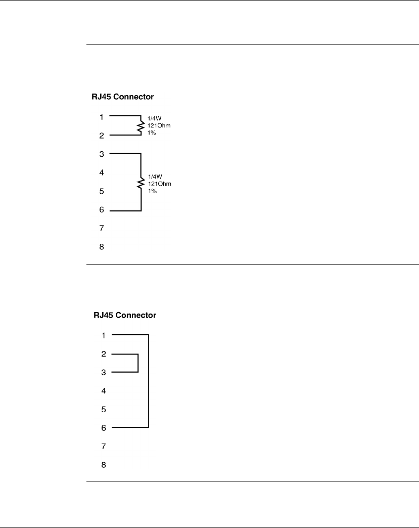
Using the Modbus Ports
140 870 USE 101 10 V.2
Pinouts for Modbus RS485 Networks, Continued
Terminating
Resistor Plugs The illustration below shows the pinout for the Modbus Plus or Modbus RS485
Terminating RJ45 Resistor Plugs:
Terminating
Shunt Plugs The illustration below shows the pinout for the Modbus RS485 Terminating RJ45
Shunt Plugs:

870 USE 101 10 V..2 141
Using the Ethernet Port
At a Glance
In This Chapter This chapter contains the following sections:
For This Topic... See Section... On Page...
Ethernet Port 1 142
Establishing a Connection with an Ethernet Module 2 158
Accessing Embedded Web Pages 3 162
171 CCC 960 30 AND 171 CCC 980 30 Web Pages 4 164

Using the Ethernet Port
870 USE 101 10 V..2 142
Section 5.1
Ethernet Port
Purpose Ethernet ports are available with:
l171 CCC 960 20 Processor Adapters
l171 CCC 960 30 Processor Adapters
l171 CCC 980 20 Processor Adapters
l171 CCC 980 30 Processor Adapters
In This Section This Section contains the following topics:
For This Topic... See Page...
Ethernet Port 143
Network Design Considerations 144
Security 146
Cabling Schemes 147
Pinouts 148
Assigning Ethernet Address Parameters 149
Using BOOTP Lite to Assign Address Parameters 152
Reading Ethernet Network Statistics 153
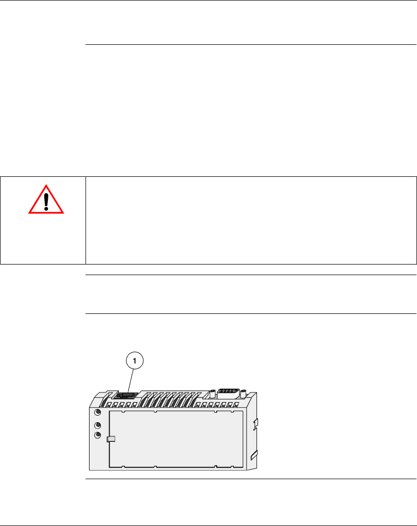
Using the Ethernet Port
870 USE 101 10 V..2 143
Ethernet Port
Introduction The Ethernet port allows a Processor Adapter to connect to an Ethernet network
for:
lhigh-speed I/O servicing
lhigh-speed data transfer
lprogramming
lworldwide connectivity via the Internet
linterfaces with a wide array of standard Modbus over TCP/IP Ethernet-aware
devices
Connector Type The Ethernet connector is a female RJ45 style phone jack.
Illustration The following illustration shows the position of the Ethernet port on a Processor
Adapter:
CAUTION
Communication Errors May Result
After taking an Ethernet Processor out of service, it is recommended that you clear the
program and IP address to prevent future conflicts.
Before installing a replacement Ethernet Processor on your network, verify that it contains
the correct IP address and program for your application.
Failure to observe this precaution can result in injury or equipment damage.

Using the Ethernet Port
870 USE 101 10 V..2 144
Network Design Considerations
Introduction In a distributed control environment, Ethernet can be used as:
lan I/O network
la supervisory network
la network that combines I/O and supervisory functions
This section discusses how to design your network to make communication
between related devices as effective and deterministic as possible.
When installed on a new network, the M1 Ethernet Processor will obtain the MAC
and IP addresses of other devices on the network. This process may require
several minutes.
When the module is successfully communicating with these devices, if a ring
adapter with battery back up is not present, it is recommended that you stop the
processor and save the user program to flash. This will save the processor’s ARP
cache and enable it to “remember” this information if power is lost or removed. If
you do not save to flash the processor must repeat acquiring the ARP cache
information from the network.
This procedure should also be followed whenever:
lA new or substitute device is installed on the network;
lThe IP address of a network device has been changed.
Continued on next page
Note: Preserve your ARP cache information.
CAUTION
CONTROL NETWORKS MUST BE ISOLATED FROM MIS DATA NETWORKS
To maintain a deterministic Ethernet network, you must isolate Momentum Processor
Adapters and related devices from MIS data networks. Traffic from MIS data networks can
interrupt communication between control devices, causing your control application to
behave unpredictably.
Additionally, the high message rates that may be generated between M1 Processors and
I/O Adapters may bog down an MIS network, causing loss of productivity.
Failure to observe this precaution can result in injury or equipment damage.

Using the Ethernet Port
870 USE 101 10 V..2 145
Network Design Considerations, Continued
I/O Networks In an Ethernet I/O network architecture, an M1 Processor Adapter is used to control
Momentum I/O points equipped with an Ethernet Communication Adapter or other
Modbus over TCP/IP Ethernet-aware devices. Communication between these
devices should be isolated not only from MIS data traffic, but also from unrelated
communication between other control devices.
You may isolate communication by creating a separate network or by using
switches.
Supervisory
Networks In a supervisory architecture, several intelligent processing devices share system
data with each other. Many kinds of devices may be part of the network. You should
be aware of each device’s requirement for access to the network and of the impact
each device will have on the timing of your network communication.
Combined
Supervisory and
I/O Handling
If your system requires both supervisory and I/O handling architectures, one
solution is to use the I/OBus capabilities of the 171 CCC 960 20 Processor Adapter
for the I/O network and the Ethernet capabilities for the supervisory network.
If you intend to use Ethernet to handle both functions, use switches to isolate the
network traffic and supply additional buffering of network packets.
Concurrent
Communication A maximum of 96 devices may be communicating with the Processor Adapter via
the Ethernet at any one time. This 96-device limit consists of:
lup to 2 programming panels (one must be in monitor mode)
lup to 14 general purpose Modbus server paths
lup to 16 MSTR elements which support Modbus read, write or read/write
commands
lup to 64 cyclic configured data slave paths
Continued on next page

Using the Ethernet Port
870 USE 101 10 V..2 146
Security
Overview To restrict access to your Ethernet controller and I/O network, you may want to
consider a firewall. A firewall is a gateway that controls access to your network.
Types of
Firewalls There are two types of firewalls:
lNetwork-level firewalls
lApplication-level firewalls
Network-Level
Firewalls Network-level firewalls are frequently installed between the Internet and a single
point of entry to an internal, protected network.
Application-
Level Firewalls An application-level firewall acts on behalf of an application. It intercepts all traffic
destined for that application and decides whether to forward that traffic to the
application. Application-level firewalls reside on individual host computers.
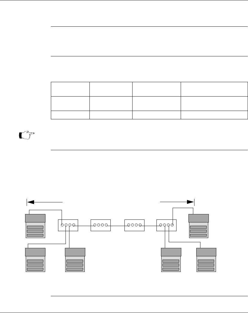
Using the Ethernet Port
870 USE 101 10 V..2 147
Cabling Schemes
Introduction In a standard Ethernet cabling scheme, each device connects via a cable to a port
on a central Ethernet hub.
Length The maximum length of cable between devices depends on the type of hub used,
as shown in the following table:
Cabling with
Traditional Hubs The following illustration shows the maximum number of hubs and the maximum
cable length between devices when using traditional (non-switching) hubs:
Type of Hub Max. Cable from
Device to Hub Max. Hubs Between
Any Two Nodes Max. Cable Between Most
Distant Nodes on Network
Traditional
(Non-switching)
100 m 4 500 m
Switches 100 m Unlimited Unlimited
Note: 10/100 hubs/switches can be used. This will allow 100 Base T networks to
use the M1E.
Cabling with
Traditional Hubs
Hub Hub
I/O Device I/O Device I/O Device I/O Device
500m (1630 ft) Maximum Cable Length
Within the Same Collision Domain
M1E M1E
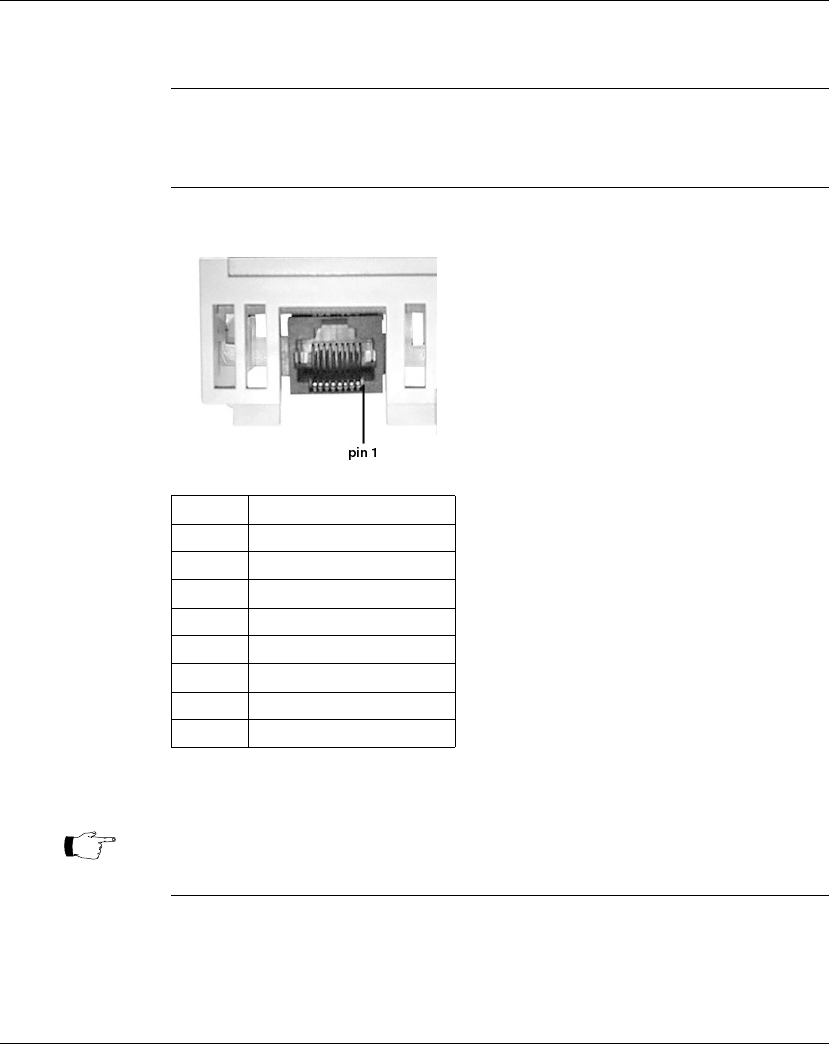
Using the Ethernet Port
870 USE 101 10 V..2 148
Pinouts
Overview This section contains pinouts for wiring an Ethernet network for Momentum
components.
RJ45 Pinout The illustration below shows the pinouts for wiring an RJ45 connector for Ethernet:
Pin Function
1 TXD +
2 TXD -
3RXD +
4
5
6RXD -
7
8
Note: These are industry standard pinouts. Prefabricated patch cables can be
used.

Using the Ethernet Port
870 USE 101 10 V..2 149
Assigning Ethernet Address Parameters
Overview As shipped from the factory, the M1 Ethernet Processor does not contain an IP
address. This is also true if you have not programmed the unit with an Ethernet
configuration extension. In this condition, when the module starts up, it will attempt
to obtain an IP address from the network’s BOOTP server.
You can use Concept to assign an IP address, default gateway and sub network
mask. See
Setting Ethernet Address Parameters
on page 348.
You can also assign IP address parameters using the BOOTP Lite software utility.
See
Using BOOTP Lite to Assign Address Parameters
on page 152.
Using a BOOTP
Server A BOOTP server is a program that manages the IP addresses assigned to devices
on the network. Your system administrator can confirm whether a BOOTP server
exists on your network and can help you use the server to maintain the adapter’s IP
address.
How an
unconfigured
(“as shipped”)
module obtains
an IP address
On startup, an unconfigured processor will attempt to obtain an IP address by
issuing BOOTP requests. When a response from a BOOTP server is obtained, that
IP address will be used. If a response is not heard, then the Bootp requests will
continue for as long as the unit remains powered or until a response is heard.
Specifying
Address
Parameters
Consult your system administrator to obtain a valid IP address and appropriate
gateway and subnet mask, if required. Then follow the instructions in
Setting
Ethernet Address Parameters
on page 348.
Continued on next page
CAUTION
DUPLICATE ADDRESS HAZARD
Be sure that your Processor Adapter will receive a unique IP address. Having two or more
devices with the same IP address can cause unpredictable operation of your network.
Failure to observe this precaution can result in injury or equipment damage.
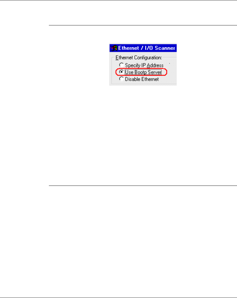
Using the Ethernet Port
870 USE 101 10 V..2 150
Assigning Ethernet Address Parameters, Continued
When the
Processor
Adapter is
Powered-up with
a Configuration
for “Use Bootp
Server”
If the processor adapter is powered up without battery backup, and its IP address
was previously saved to flash, the adapter will issue three Bootp requests five
seconds apart.
lIf a Bootp response is received from the server, the IP address will be assigned
but will not be saved to flash. Use the programming software to save the IP
address to flash. If a power cycle occurs on the processor adapter, the IP
address that is currently saved in flash will be used.
lIf a Bootp response is not received from the server, the processor adapter will
use the IP address that is stored in flash. Three ARP broadcasts are made, five
seconds apart, to check for duplicate IP addresses. Then, three gratuitous
ARP broadcasts are made two seconds apart with the station’s MAC address
and IP address.
Continued on next page

Using the Ethernet Port
870 USE 101 10 V..2 151
Assigning Ethernet Address Parameters, Continued
When the
Processor
Adapter is
Power-up with a
Configuration for
“Specify IP
Address”
If the processor adapter is powered-up without battery backup and its IP address
was previously saved to flash; the adapter will listen for any Bootp messages but
will not will not issue any Bootp requests. Instead it will use the IP address that is
specified in the configuration. Then, three ARP broadcasts are made, five seconds
apart, to check for duplicate a IP address. Then, three gratuitous ARP broadcasts
are made, two seconds apart, with the station’s MAC address and IP address.
To Retain the IP
Address After setting the module’s IP address, you must save it to flash memory if you want
this setting to be retained when power is removed from the module. This is
necessary even if the module is attached to a ring adapter that provides battery
back up. See
Saving to Flash with Concept
on page 399.

Using the Ethernet Port
870 USE 101 10 V..2 152
Using BOOTP Lite to Assign Address Parameters
Specifying
Addresses/
Stopping the
Processor
Instead of a BOOTP server, Schneider Electric’s BOOTP Lite utility software can be
used to provide the IP address, subnet mask and default gateway to the processor.
A response from BOOTP Lite will cause the processor to enter Stopped mode on
completion of power up, if the processor has been set to “Specify IP Address”
mode via Concept. This is useful when inappropriate outbound network traffic might
result if the processor immediately transitioned into Run mode after power up.
Refer to the BOOTP Lite user documentation for instructions.
CAUTION
INCORRECT MAC ADDRESS HAZARD
Be sure to verify the MAC address of the target device before invoking BOOTP Lite. If you
do not enter the correct parameters of the target controller, it will run in its old configuration.
An incorrect MAC address may also result in an unwanted change to another device and
cause unexpected results.
Failure to observe this precaution can result in injury or equipment damage.
Note: BOOTP Lite and the user document are available for download at
www.modicon.com.

Using the Ethernet Port
870 USE 101 10 V..2 153
Reading Ethernet Network Statistics
Overview Ethernet Network statistics are stored in the processor adapter and can be viewed
by the user.
Procedure The M1 ethernet Processor Adapter’s Ethernet Network Statistics can be viewed
using the Network Options Ethernet Tester. This software utility is available with the
Quantum 140 NOE 771 00 10/100 Megabit Ethernet Module User Guide
840 USE
116 00.
Table of
Statistics Network statistics occupy word 4 through word 35 in the Modbus Status Table, as
follows:
Table 1: TCP/IP Ethernet Statistics Table
Word Data
00 ... 02 MAC Address
03 Board Status
04, 05 Rx Interrupt
06, 07 Tx Interrupt
08, 09 NA
10, 11 Total Collisions
12, 13 Rx Missed Packet Errors
14, 15 NA
16, 17 Chip Restart Count
Lo word – Collison Peak Detector
18, 19 Framing Errors (Giant Frame Error)
20, 21 Overflow Errors
22, 23 CRC Errors
24, 25 Receive Buffer Errors (Out of Server Paths)
26, 27 Transmit Buffer Errors
28, 29 Silo Underflow (TCP retries)
30, 31 Late Collision
32, 33 Lost Carrier
34, 35 16 Collision Tx Failure
36, 37 IP Address

Using the Ethernet Port
870 USE 101 10 V..2 154
Description
Operational Statistics
Words 4, 5
Receive
Interrupts
Number of frames received by this station. Only broadcast frames pertinent to this
station and individual address match frames are received and counted.
Words 6, 7
Transmit
Interrupts
Number of frames transmitted from this station. Includes all transmitted broadcast
frames for ARP and BOOTP.
Ethernet Network Functioning Errors
Words 8, 9 Not used.
Words 10, 11
Total Collisions This field contains the total number of transmit collisions.
Words 12, 13 Rx
Missed Packet
Errors
Receive frame was missed because no buffer space was available to store the
frame. Indicates firmware unable to keep up with link. The only time this should
increment is during the save user logic to flash command, when all
interrupts are disabled for 10 seconds.
Words 14, 15 Not used.
Continued on next page

Using the Ethernet Port
870 USE 101 10 V..2 155
Description, Continued
Words 16, 17 High Word: Not used, always 0
Low Word: Peak Collision Detector
This field contains the number of consecutive collisions that occurred before the
frame was successfully transmitted out onto the Ethernet. Most transmitted frames
have zero collisions. Some have one collision on the first transmit attempt and
succeed on the second attempt. Some have more than one collision followed by
success. The largest number of consecutive collisions, since clear statistics
command, is stored and displayed in this field.
Receiver Errors
Words 18, 19
Framing Errors Counts the number of received frames addressed to this node that are greater than
320 bytes in length. Any such large frame has no relevance to the M1 Ethernet
adapter and therefore is skipped.
This error should not occur.
Overflow Errors Increments whenever a received frame cannot be copied into the frame buffer,
because the frame buffer is full. This situation should never occur under legal
Ethernet traffic.
Words 20, 21
CRC Errors Increments when the received packet is received under any of the following error
conditions:
lCRC error
lExtra data error
lRunt error
This counter can be made to increment by continuously disconnecting and
reconnecting the M1 Ethernet cable during cyclic communication.
Continued on next page

Using the Ethernet Port
870 USE 101 10 V..2 156
Description, Continued
Words 24, 25
Receive Buffer
Errors
Increments whenever a client attempts to connect to the M1 Ethernet, and fails,
because there is no available server path. The M1 Ethernet supports 14
simultaneous data paths and 2 program paths before this counter can increment.
This error indicates poor application architecture.
Transmission Errors
Words 26, 27
Transmit Buffer
Errors
Increments when the M1 is unable to transmit an Ethernet response frame because
all frame buffers are in use. For example, the M1 has 16 PING reply buffers. If all
16 PING buffers contain PING replies, ready to be transmitted, but this station’s
transmission is delayed because of collisions and backoff, and one more PING
request is received, then the new PING request is discarded and the counter is
incremented. This error can occur for PING, ARP, and connection attempt to server
path. Although this error is theoretically possible, it is not usually encountered.
Words 28, 29 Silo
Underflow This field counts M1 TCP/IP retries. All M1 clients and server use the TCP/IP
protocol which implements sequence numbers and timeouts. Whenever TCP/IP
data is pushed from the M1, a subsequent acknowledgement of receipt of M1 data
must be received within the timeout period, or else the M1 issues a retry. Retries
may be the result of any of the following conditions:
lThe original M1 data frame was garbled, corrupted, and lost
lThe target TCP/IP stack is operating more slowly than the M1 retry rate
For Modbus 502 servers, the M1 initiates retries after (1, 1, 2, 2, 4, 8) seconds.
For Modbus 502 clients, the M1 retry rate is the larger of:
l1/4 the health timeout for Ethernet I/O Scanner data (see
Accessing the
Ethernet / I/O Scanner Screen
on page 345,
OR:
l4 times the previous measured TCP/IP round trip time for i/o Scanner MSTR
block.
Continued on next page

Using the Ethernet Port
870 USE 101 10 V..2 157
Description, Continued
Words 30, 31
Late Collision Increments when the transmit frame process is aborted because of late collision
detected after the first 64 bytes of the frame was transmitted collision free. This
error could possibly occur if the Ethernet cable is intermittently connected and
disconnected.
Words 32, 33
Lost Carrier Increments whenever the Ethernet cable, connected to the M1, is disconnected
from the hub. Also increments whenever the Ethernet cable, connected to the hub,
is disconnected from the M1.
Words 34, 35
16 Collision
Transmit Failure
Transmit frame process was aborted after 16 consecutive collisions. The frame
was not successfully transmitted out onto Ethernet link. This error should never
occur.

Using the Ethernet Port
870 USE 101 10 V..2 158
Section 5.2
Establishing a Connection with an Ethernet Module
Overview
Introduction This Section presents an overview of the procedure for connecting to an ethernet
module that is used as a web server. For a complete description of the Quantum
140 NOE 771 x0 module, refer to
Quantum NOE 771 x0 Ethernet Modules User
Guide
840 USE 116 00 Version 1.0.
What’s in this
Section This Section contains the following topic:
Note: To establish a connection with an Ethernet module using the Network
Options Ethernet Tester, you must know the module’s IP network address
or host name.
Topic Page
Establishing a Connection with an Ethernet Module 159
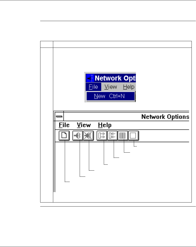
Using the Ethernet Port
870 USE 101 10 V..2 159
Establishing a Connection with an Ethernet Module
Procedure Perform the following steps to establish a connection with an Ethernet module
using the Network Options Ethernet Tester:
Continued on next page
Step Action
1From the initial menu, select File and choose New from the options in the
pulldown menu
or
click on the new connection button in the toolbar.
This will bring up the Remote IP Address dialog box.
Create new connection
Connect
Disconnect
Read register
Write register
Get statistics
Clear statistics
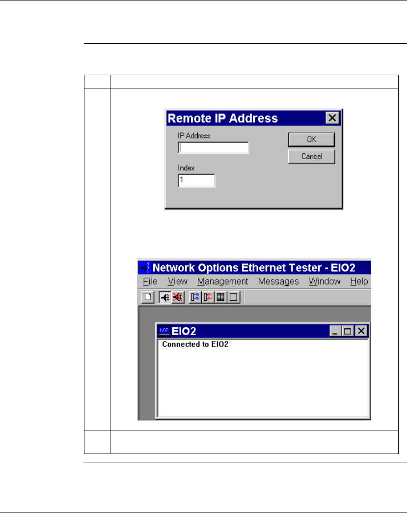
Using the Ethernet Port
870 USE 101 10 V..2 160
Establishing a Connection with an Ethernet Module, continued
Procedure,
continued
Continued on next page
Step Action
2Type the module’s IP network address or host name in the IP Address box.
Click on the OK button. This dedicates a connection from your PC to the
designated Ethernet module and brings you to the main menu.
3You may establish several connections with the same module or with other
modules by repeating step 2 for each new connection.
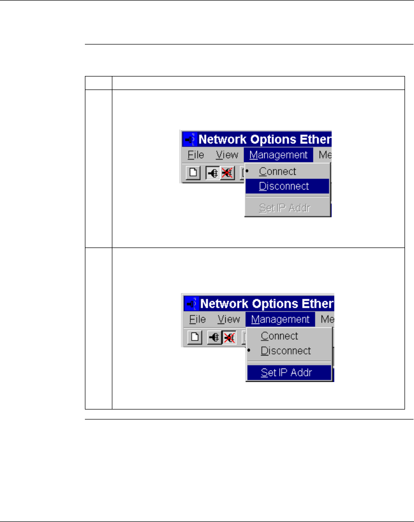
Using the Ethernet Port
870 USE 101 10 V..2 161
Establishing a Connection with an Ethernet Module, continued
Procedure,
continued
Step Action
4When you are ready to disconnect, select Management and choose Disconnect
from the pulldown menu:
or
click on the disconnect button in the toolbar.
5After disconnecting from one module, you may reassign its dedicated connection
by selecting Management and choosing Set IP Addr from the pulldown menu.
Type the new IP network address or host name in the box provided.

Using the Ethernet Port
870 USE 101 10 V..2 162
Section 5.3
Accessing Embedded Web Pages
Overview
Introduction This Section presents a brief overview of accessing the embedded web pages
contained in the Momentum M1E 171 CCC 960 30 and 171 CCC 980 30 IEC
modules. The Momentum M1E 171 CCC 960 30 and 171 CCC 980 30 IEC
modules’ Web pages enable you to access diagnostic information, view
configuration information, and change the online configurations for the module.
What’s in this
Section This Section contains the following topics:
Topic Page
Accessing the Web Utility Home Page 163
Momentum M1E Indicator 170

Using the Ethernet Port
870 USE 101 10 V..2 163
Accessing the Web Utility Home Page
Introduction Each Momentum M1E 171 CCC 960 30 and 171 CCC 980 30 IEC PLC contains a
World Wide Web embedded server that allows you to access diagnostics and
online configurations for the controller. Pages on the embedded web site display:
lthe Ethernet statistics for the node
lthe controller’s register values
The web pages can be viewed across the World Wide Web using version 4.0 or
greater of either Netscape Navigator or Internet Explorer, both of which support
JDK 1.1.4 or higher.
For information on the additional functionality provided by the FactoryCast system
in the Momentum M1E 171 CCC 960 30 and 171 CCC 980 30 IEC modules, see
the
FactoryCast User’s Guide For Quantum and Premium
, 890 USE 152 00.
How to Access It Before you can access the module’s home page, you must learn its full IP address
or URL from your system administrator. Type the address or URL in the Address or
Location box in the browser window. Once you do this the Schneider Automation
Web Utility home page will appear (see next section).

Using the Ethernet Port
870 USE 101 10 V..2 164
Section 5.4
171 CCC 960 30 AND 171 CCC 980 30 Web Pages
Overview
Introduction This Section shows the embedded Web pages contained in the Momentum M1E
171 CCC 960 30 AND 171 CCC 980 30 IEC modules and a brief description of
each page.
What’s in this
Section This Section contains the following topic:
Topic Page
Momentum M1E Web Pages 166
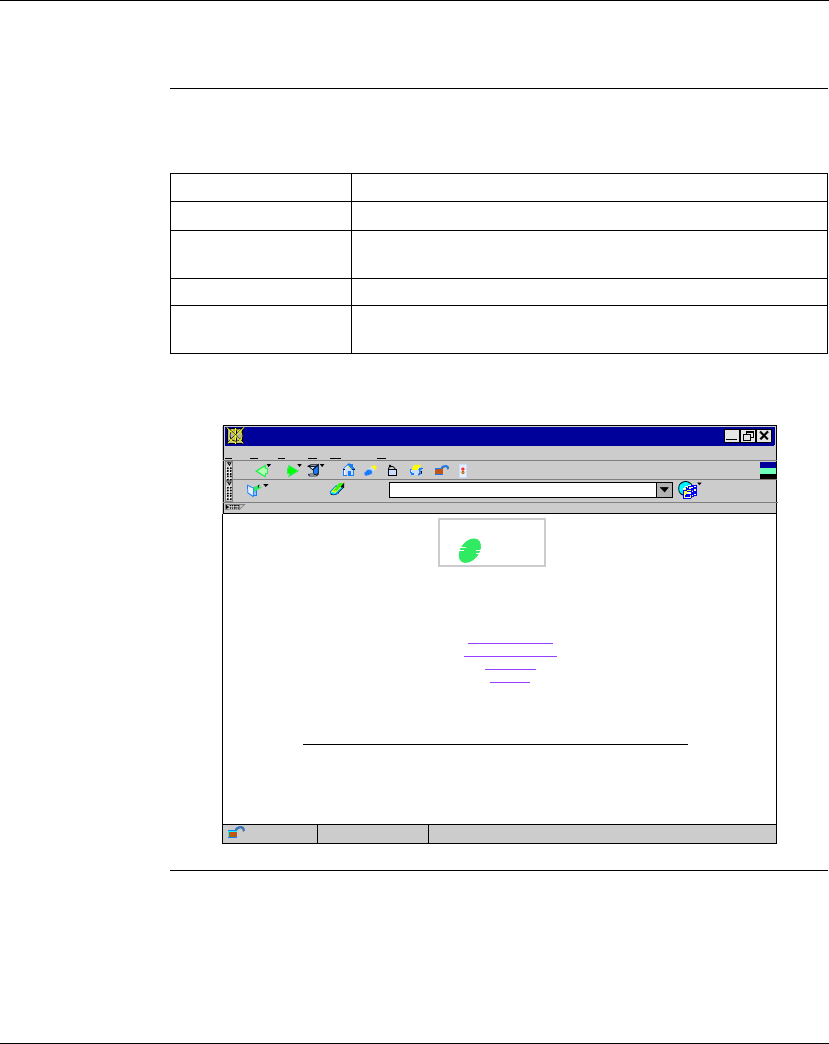
Using the Ethernet Port
870 USE 101 10 V..2 165
Momentum M1E Web Pages
Momentum M1E
Welcome Page The Momentum M1E Welcome Page provides links to the Controller Configuration,
Ethernet Statistics, I/O Status and Support Pages.
Continued on next page
Link Results
Controller Status Displays the CPU Configuration page.
Ethernet Statistics Displays the Ethernet Module Statistics with the Reset Counters
page.
I/O Status Displays the I/O Status and Configuration page.
Support Displays contact information for technical assistance, sales, and
feedback.
Schneider
Electric
S
Schneider Automation Inc.,© 1998-2000 v1.0
Welcome to the M1E Web Server - Netscape
http://eio4
M y
File Edit View GoWindow Help
Bookmarks Location What’related
Momentum Web Server
Controller Status
Ethernet Statistics
I/O Status
Support
Document Done
N
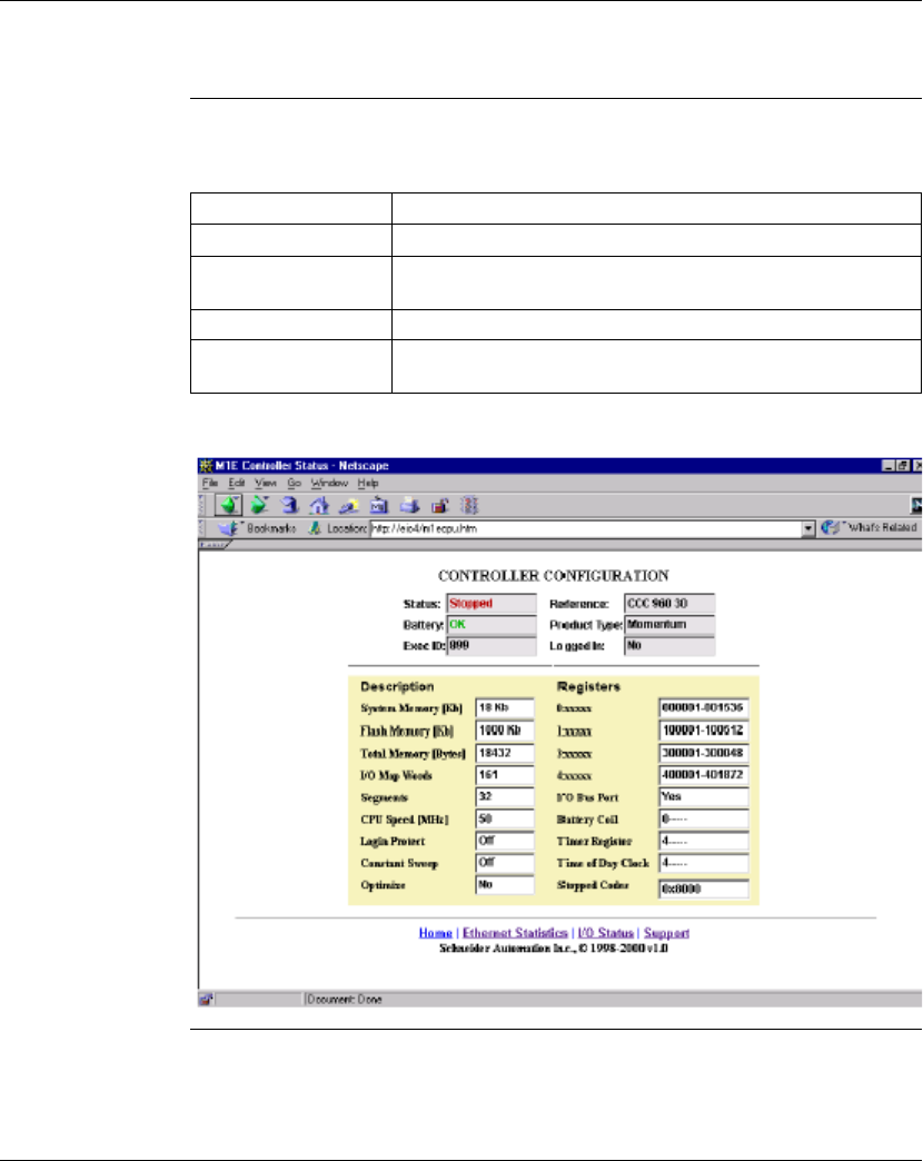
Using the Ethernet Port
870 USE 101 10 V..2 166
Momentum M1E Web Pages, Continued
CPU
Configuration
Page
The CPU Configuration Page enables you to monitor your controller configuration
and its status. It has the following links:
Continued on next page
Link Results
Home Returns you to the Home Page.
Ethernet Statistics Displays the Ethernet Module Statistics with the Reset Counters
page.
I/O Status Displays the I/O Status and Configuration page.
Support Displays contact information for technical assistance, sales, and
feedback.
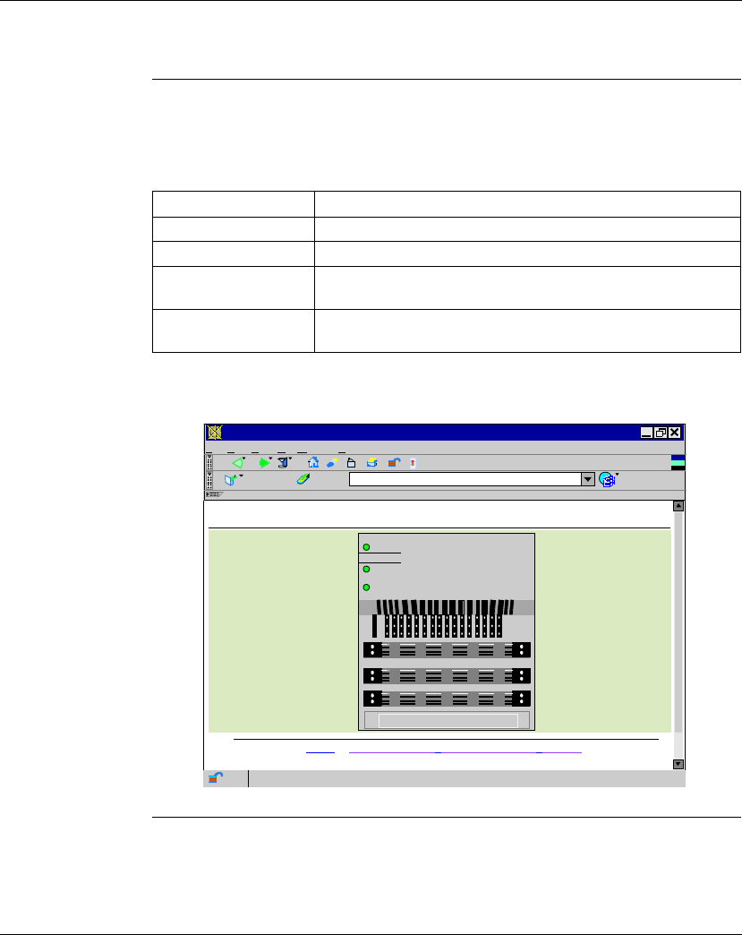
Using the Ethernet Port
870 USE 101 10 V..2 167
Momentum M1E Web Pages, Continued
M1E I/O Status
Page The I/O Status page enables you to check your I/O Status. It contains the following
links and LED indicators.
The following table describes the links contained within the I/O Status page:
Continued on next page
Link Results
Home Returns you to the Home Page.
Controller Status Displays the CPU Configuration page.
Ethernet Statistics Displays the Ethernet Module Statistics with the Reset Counters
page.
Support Displays contact information for technical assistance, sales, and
feedback.
M1E I/O Statistics - Netscape
http://eio4/iostat.htm
M y
File Edit View GoWindow Help
Bookmarks Location What’s related
Applet com. schneider automation. sysdiag.qbf. M1IO Applet running
N
Home / Controller Status / Ethernet Statistics / Support
Schneider Automation Inc.,© 1998-2000 v1.0
M1E I/O STATUS
Schneider
Automation Inc.
RUN
ETHERNET
LAN
ACT
LAN
ST 171 CCC ??? ??
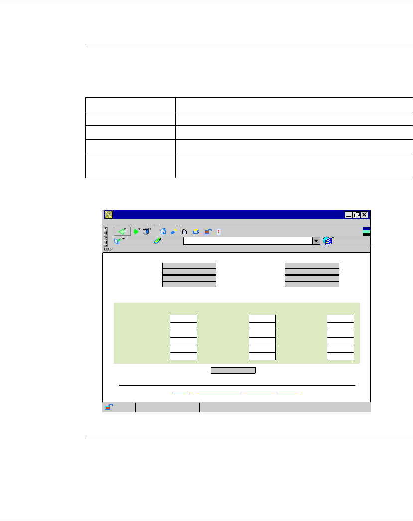
Using the Ethernet Port
870 USE 101 10 V..2 168
Momentum M1E Web Pages, Continued
Ethernet
Statistics The Ethernet Statistics page enables you to monitor ethernet information, such as
MAC Address, receive/transmit statistics and check functioning errors. It contains
the following links::
Continued on next page
Link Results
Home Returns you to the Home Page.
Controller Status Displays the CPU Configuration page.
I/O Status Displays the I/O Status and Configuration page.
Support Displays contact information for technical assistance, sales, and
feedback.
M1E Ethernet Statistics - Netscape
http://eio4/ethernet.htm
M y
File Edit View GoWindow Help
Bookmarks Location What’s related
N
64083
0
0
0
0
2
M1 ETHERNET STATISTICS
Home / Contoller Status / I/O Status / Support
Schneider Automation Inc.,© 1998-2000 v1.0
Transmit Statistics
Status:
Reference:
Firmware Version:
Host Name:
MAC Address:
Subnet Mask:
IP Address:
Gateway Address:
71956
0
0
0
0
4
36
0
0
0
Reset Counters
Transmits Receive Statistics Functioning Errors
Transmit Retries
Lost Carrier
Late Collision
Transmit Buffer Errors
TCP Retries
Receives
Framing Errors
Overflow Errors
CRC Errors
Out of server Paths
Missed Packets
Collision Errors
Transmit Timeouts
Memory Errors
Net Restarts
Document Done
Stopped
CCC 960 30
1.04
eio4
00 00 54 10 17 94
205.217.193.74
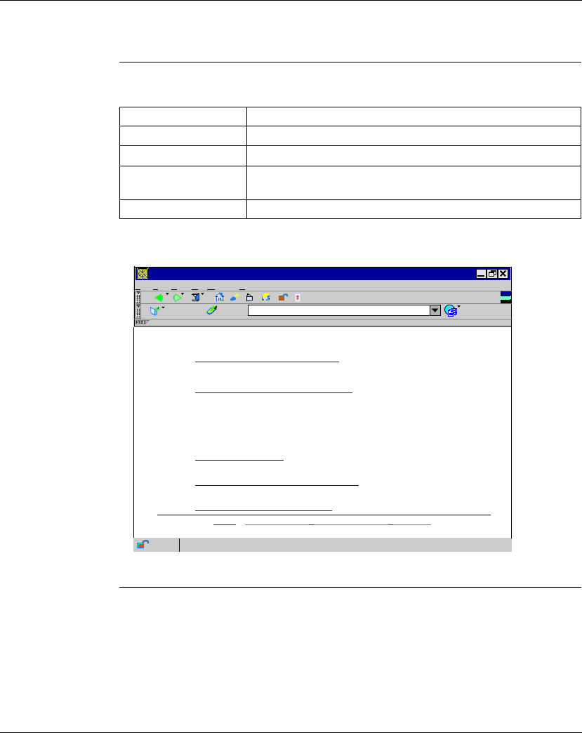
Using the Ethernet Port
870 USE 101 10 V..2 169
Momentum M1E Web Pages, Continued
Support Page The Support page contains assistance information and the following links:
Link Results
Home Returns you to the Home Page.
Controller Status Displays the CPU Configuration page.
Ethernet Statistics Displays the Ethernet Module Statistics with the Reset Counters
page.
I/O Status Displays the I/O Status and Configuration page.
Schneider Automation Support - Netscape
http://eio4/support.htm
M y
File Edit View GoWindow Help
Bookmarks Location What’s related
N
Home / Contoller Status / Ethernet Statistics / I/O Status
Schneider Automation Inc.,© 1998-2000 v1.0
Applet. com.schneiderautomation.sysdiag.qbf.M1IOApplet.stopped
Contacting Schneider Automation
There are numerous ways to reach us for assistance:
Technical Information
Visit the Schneider Automation web site.
Technical Assistance
If you need technical assistance with a product or service, contact us by mail at
customercentral@schneiderautomation.com, or telephone us at 1-800-468-5342 or
1-978-975-9700.
Noto: Be sure to supply your name, telephone number, company name and address
within your email to assure a immediate response.
Feedback
Thoughts, comments, ideas about our site? Please let us know by contacting us at
feedback@modicon.com
U.S Sales Office
Look up a location of a Sales Office in the US.
Other Transparent Factory Products
Visit out Transparent Factory web site.

Using the Ethernet Port
870 USE 101 10 V..2 170
Momentum M1E Indicators
Processor
Adapter LED
Indicators
The Momentum M1E 171 CCC 960 30 AND 171 CCC 980 30 Processor Adapter
IEC modules have three LED indicators. The LED indicators are described in the
table below:
I
I/O Status LED
Indicators There are three rows of 16 I/O Status LED indicators. :
LED Function
RUN Indicates the run state of the M1E Processor Adapter IEC module.
LAN ACT Always appear to be ”on” continuously.
LAN ST Always appear to be ”on” continuously.
Note: Each I/O base has a custom LED display that provides information about
the I/O Status.
For information about the I/O Status for your I/O base, refer to LED
Illustration and Description for your I/O base in 870 Use 002 00 V. 2
Momentum I/O Base User Guide.

870 USE 101 10 V.2 171
Using the I/OBus Port
At a Glance
Purpose Three Momentum components offer I/OBus master capabilities:
l 171 CCS 760 00 Processor Adapter
l 171 CCC 760 10 Processor Adapter
l171 CCC 960 20 and 171 CCC 960 30 Processor Adapters
This section describes the I/OBus port, explains how I/OBus works, provides
guidelines for creating I/OBus networks with Momentum components, and
describes recommended cable accessories.
In This Chapter This chapter contains the following topics:
For This Topic... See Page...
I/O Bus Port 172
How I/OBus Works 173
Network Status Indication in the M1 Ethernet Module 174
Guidelines for I/OBus Networks 175
Cable Accessories 177
Pinouts 179
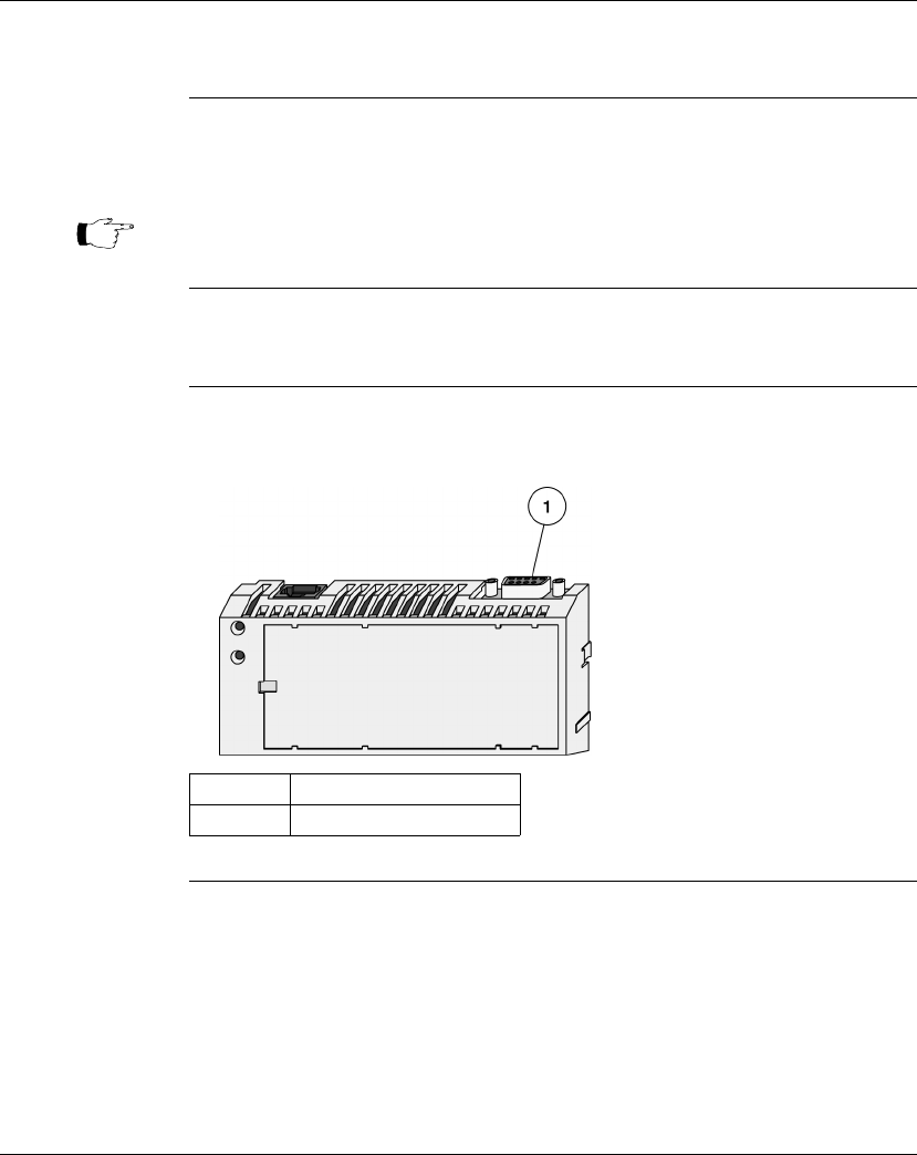
Using the I/OBus Port
172 870 USE 101 10 V.2
I/O Bus Port
Introduction The I/OBus port allows a Momentum CPU to assume bus master capabilities over
as many as 255 slave devices over an Interbus cable.
Connector Type The I/OBus port has a female 9-pin D-shell connector.
Illustration The following illustration shows the position of the I/OBus port on a Processor
Adapter:
Note: Processors that support IEC are limited to a maximum number of 1408
used I/O points, regardless of the number of modules.
Label Description
1 I/OBus port

Using the I/OBus Port
870 USE 101 10 V.2 173
How I/OBus Works
Introduction This section describes how signals are passed and how data is transferred in an
I/OBus network.
How Signals Are
Passed I/OBus operates as a logical ring, with signals being passed by the master over a
remote bus cable to each slave device in series. The slaves return signals to the
master over the same cable.
How Data is
Transferred The I/OBus functions as a logical shift register. The application’s entire data stream,
originating at the master, is transferred serially from slave to slave down the remote
bus. Each slave regenerates the entire stream before passing it on. As a slave
handles the stream data, it extracts the portion that is assigned to it and adds any
output data to the stream.
Transmission
Speed Data is transmitted at 500 kbits/s.
Amount of data The number of 16 bit words in the data stream is dependent on the processor
model:
Model Max Input Words Max Output Words
171 CCS 760 00 128 128
171 CCC 760 10 256 256
171 CCC 960 20 256 256
171 CCC 960 30 256 256
Note: Processors that support IEC are limited to a maximum number of 1408
used I/O points, regardless of the number of modules.

Using the I/OBus Port
174 870 USE 101 10 V.2
Network Status Indication in the M1 Ethernet Module
Overview The M1 Ethernet Module can provide I/OBus network status via the Module Status
function in the programming panel or by a STAT element in user logic. The fourth
word of the status element contains information regarding the integrity of the
network.
Operation The I/OBus status word contains a valid value only when the processor is running.
A zero value indicates that normal I/OBus communication is occurring.
A non-zero value indicates a problem.
Failure
Indication If there is a communications error, bit values in the I/OBus status word contain
information on the failure mode, as follows:
BITS 0 - 14 These bits contain a value from 1 to 255, signifying the network position of the
module that cannot be reached. For example, a value of 8 indicates a
communications failure in accessing the 8th module on the network.
BIT 15 This bit contains a value of 0 or 1.
A value of zero indicates a general communication failure, for example, no power to
the module or a break in its input cable.
A value of 1 indicates that communication is possible, but the I/OBus ID received
from the module does not match the module type contained in the traffic cop for
that position.

Using the I/OBus Port
870 USE 101 10 V.2 175
Guidelines for I/OBus Networks
Overview This section gives guidelines for creating an I/OBus network using a Momentum
CPU as bus master.
Length The maximum distance between the Momentum CPU master and the farthest slave
is 13 km (8 mi).
Distance
Between Nodes The maximum distance between nodes is 400 m (1300 ft.).
Number of
Devices A network may consist of as many as 256 nodes, including one Momentum CPU
bus master and up to 255 slave I/O devices.
Acceptable Slave
Devices An I/OBus slave device can be:
lA Momentum I/O base with a 170 INT 110 00 Interbus Communication Adapter
mounted on it
lA Modicon Terminal Block I/O module enabled for Interbus communications
lA standard Interbus module designed by a third party manufacturer
Unacceptable
Slave Devices The I/OBus network does not support Interbus-compatible devices that require the
Interbus PCP protocol.
Continued on next page
Note: Processors that support IEC are limited to a maximum number of 1408
used I/O points, regardless of the number of modules.
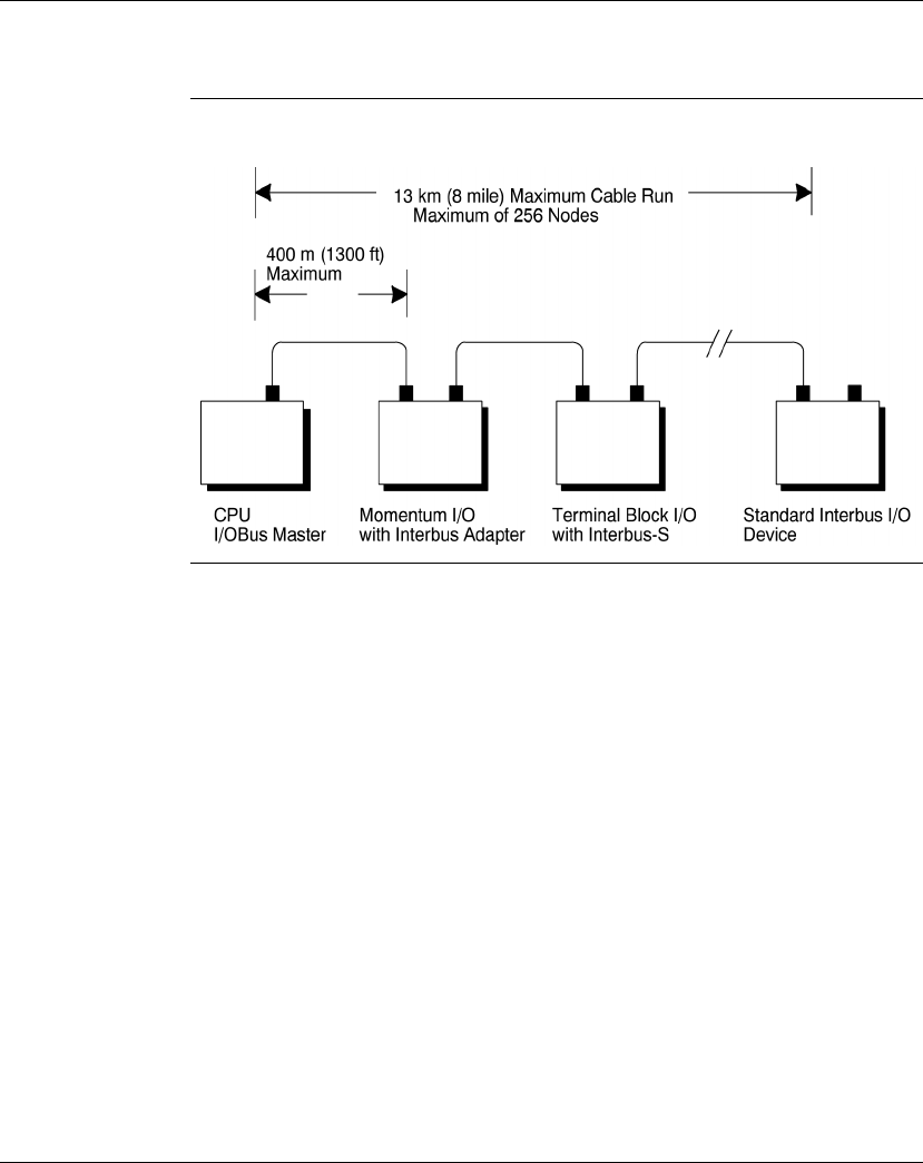
Using the I/OBus Port
176 870 USE 101 10 V.2
Guidelines for I/OBus Networks, Continued
Network Scheme The slave devices are distributed along a trunk, as shown in the illustration below.
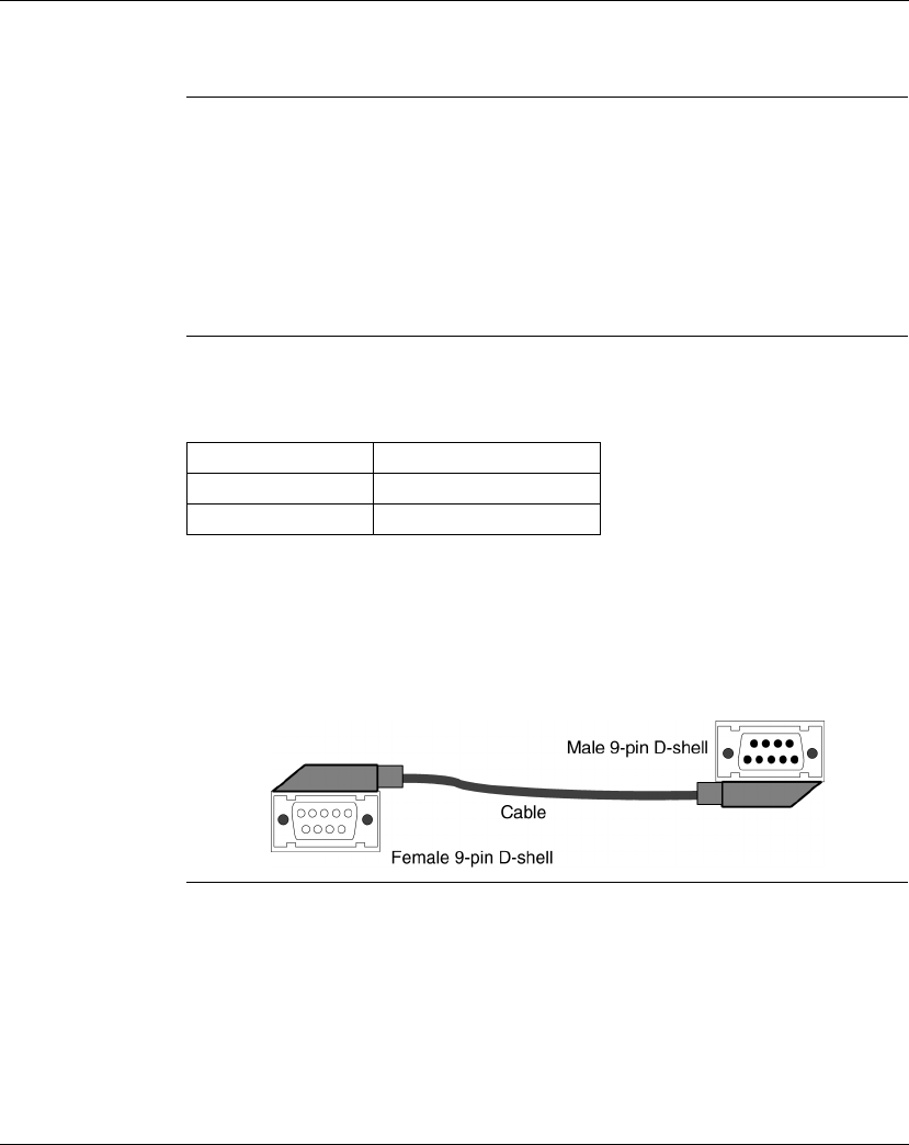
Using the I/OBus Port
870 USE 101 10 V.2 177
Cable Accessories
Overview Modicon provides several cabling solutions for I/OBus:
lLow profile cables in two lengths
lA 1m cable with high profile rear shell
lA connector kit for building custom-length Interbus cables
This section describes those solutions.
Low Profile
Cables For side-by-side mounting of the CPU with Interbus I/O modules on a DIN rail or
wall, Modicon provides two specially molded low profile cables.
These cables have a male 9-in D-shell connector on one end and a female 9-pin D-
shell on the other. The male connector plugs into the female I/OBus port on the
Processor Adapter, and the female connector plugs into the male connector on the
left side of a 170 INT 110 00 Interbus Communications Adapter on an I/O base.
Additional cables can then be used to connect a series of I/O modules via their
Interbus communication ports.
Continued on next page
Part Number Length
170 MCI 007 00 11.4 cm (4.5 in)
170 MCI 100 01 100 cm (39 in)

Using the I/OBus Port
178 870 USE 101 10 V.2
Cable Accessories, Continued
Interbus Cable
Connector Kit I/OBus communicates over Interbus full duplex cable. For custom cable lengths,
Modicon offers an Interbus cable connector kit (part number 170 XTS 009 00). The
kit includes two connectors, one male and one female, that can be soldered to an
Interbus full duplex cable of the appropriate length.
The recommended cable is Belden 3120A or equivalent. Belden 8103 is an
acceptable alternative.
Note: The connectors in the 170 XTS 009 00 Kit are high profile.
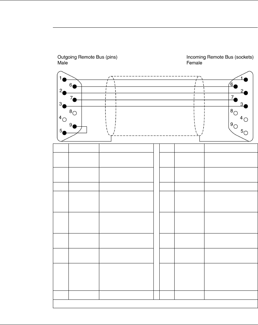
Using the I/OBus Port
870 USE 101 10 V.2 179
Pinouts
Interbus Cable The following illustration shows how to wire the connectors of the remote bus
cable:
Pin Wire Color Outgoing Connection Pin Wire Color Ingoing Connection
1 Yellow DO
Data Out
1 Yellow DO
Data Out
2 Gray DI
Data In
2 Gray DI
Data In
3 Brown Common 3 Brown Common*
4 GND
Reference conductor,
fiber-optic adapter
4GND*
Reference conductor,
fiber-optic adapter
5 Vcc
Power-supply for fiber-
optic adapter
5 Vcc*
Power-supply for fiber-
optic adapter
6 Green DO_N
Data Out Negated
6 Green DO_N
Data Out Negated
7 Pink DI_N
Data In Negated
7 Pink DI_N
Data In Negated
8Vcc
Additional power
supply for fiber-optic
adapter
8 Vcc*
Additional power
supply for fiber-optic
adapter
9 Plug identification 9 Not used
* Physically isolated

Using the I/OBus Port
180 870 USE 101 10 V.2

870 USE 101 10 V.2 181
Using the Modbus Plus Ports
At a Glance
Purpose Modbus Plus ports are available with:
l172 PNN 210 22 Option Adapter (Single Port)
l172 PNN 260 22 Option Adapter (Redundant Ports)
This section gives an overview of Modbus Plus networks for Momentum
components.
In This Chapter This chapter contains the following topics:
Note: The
Modbus Plus Network Planning
and Installation Manual
(890 USE 100 00) provides details for the complete design and
installation of a Modbus Plus cable system.
For This Topic... See Page...
Modbus Plus Features for Momentum 182
Two Types of Modbus Plus Networks 183
Standard Cabling Schemes 185
Cluster Mode Cabling Schemes 187
Cable Accessories for Modbus Plus Networks 191
Pinouts and Wiring Illustrations for Modbus Plus Networks 194
Modbus Plus Addresses 198
Peer Cop 200

Using the Modbus Plus Ports
182 870 USE 101 10 V.2
Modbus Plus Features for Momentum
Introduction When a Modbus Plus network is constructed entirely of Momentum components, it
may take advantage of two new features:
lcluster mode, which allows small groups of devices to be linked by short
lengths of cable;
lsupporting up to 64 nodes on a
single
section of cable.
Cluster Mode A cluster may consist of up to eight Momentum devices. A network may contain up
to eight clusters.
The cable between devices in a cluster may be 10 in to 3 ft. The cable between
clusters or between a cluster and the trunk must be at least 10 ft.
The maximum length of the network continues to be 1500 ft. The maximum number
of devices in a network continues to be 64.
64 Nodes When a Modbus Plus network consists entirely of Momentum devices, then a
single section of cable may support 64 nodes instead of the standard 32 nodes.
Example: If a single SA85 is added to a network of Momentum modules, the
network is no longer Momentum only, but a mixture of devices. Each cable section
must be limited to 32 nodes. Cable sections must be connected by a repeater.
Note: Only Momentum devices are allowed in a cluster.

Using the Modbus Plus Ports
870 USE 101 10 V.2 183
Two Types of Modbus Plus Networks
I/O Networks and
Supervisory
Networks
In a distributed control environment, Modbus Plus can be used in either of two
ways:
lAs an
I/O network
lAs a supervisory network
I/O Networks In a deterministic I/O network architecture, one CPU services up to 63 Momentum
I/O modules, Terminal I/O modules or other Modbus Plus devices.
Supervisory
Networks In a supervisory architecture, several intelligent processing devices share system
data with each other. Many kinds of devices may be part of the network. You should
be aware of each device’s requirement for access to the network and of the impact
each device will have on the timing of your network communication, especially
when servicing non-critical (and non-deterministic) I/O.
Continued on next page
CAUTION
CRITICAL I/O MUST BE SERVICED IN AN I/O NETWORK
Design your Modbus Plus architecture to meet the needs of your network. Modbus Plus can
offer deterministic I/O servicing or non-deterministic supervisory servicing of programming,
user interface, and third party ModConnect devices. Do not use a supervisory network to
service critical I/O.
Failure to observe this precaution can result in injury or equipment damage.
Note: When a programming panel or other human-machine interface (HMI)
device is used as part of a deterministic Modbus Plus I/O network, it
should be connected via the RS232 port on the CPU, not as a Modbus
Plus node.

Using the Modbus Plus Ports
184 870 USE 101 10 V.2
Two Types of Modbus Plus Networks, Continued
What if I Need
Both Types? If your system requires both supervisory and I/O handling architectures, one
solution is to use a Processor Adapter with I/OBus capabilities as the I/O network
and either a 172 PNN 210 22 or 172 PNN 260 22 Option Adapter with Modbus Plus
for the supervisory network.

Using the Modbus Plus Ports
870 USE 101 10 V.2 185
Standard Cabling Schemes
Introduction In a standard Modbus Plus cabling scheme, each peer device connects via a drop
cable to a tap along a trunk cable.
Length The maximum length of cable from one end of the network to the other is 1500 ft.
(450 m) if no repeaters are used.
You can use up to three Modicon RR85 Repeaters to extend the cable to up to
6000 ft. (1800 m). Each repeater allows you to extend the cable 1500 ft. (450 m).
Distance
Between Nodes Nodes must be separated by at least 10 ft. of cable. This requirement is more than
satisfied by standard drop cables:
Number of
Devices The maximum number of devices in a network is 64:
lIf you use only Momentum products, you may use up to 64 devices on one
cable section without a repeater.
lIf you use a mixture of devices, you may use up to 32 devices on one cable
section. You must use a repeater to connect to another cable section. You may
use up to three repeaters and four cable sections in all.
Termination You must terminate both ends of the network. If your network consists of two or
more sections separated by a repeater, each section must be terminated at both
ends.
Continued on next page
Description Part Number
Modicon RR85 Repeater NW-RR85-000
Description Part Number
Modbus Plus Drop Cable, 2.4 m / 8 ft. 990 NAD 211 10
Modbus Plus Drop Cable 6 m / 20 ft. 990 NAD 211 30
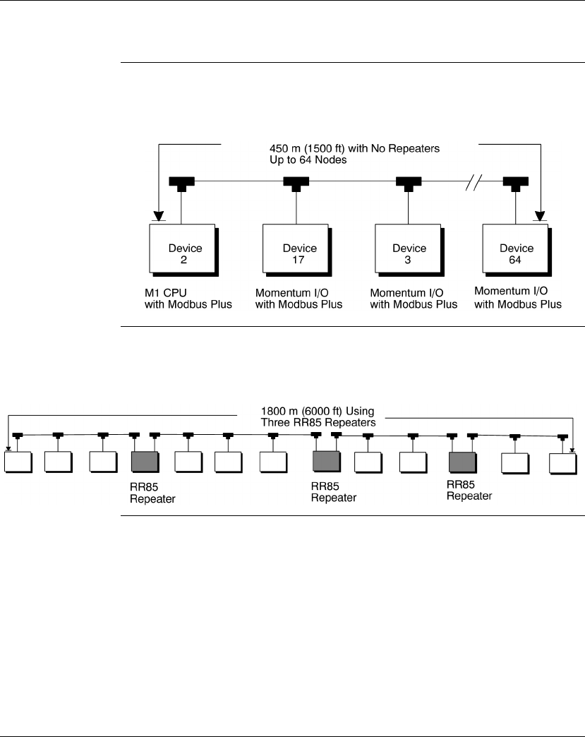
Using the Modbus Plus Ports
186 870 USE 101 10 V.2
Standard Cabling Schemes, Continued
Momentum
Network This illustration depicts a Modbus Plus network constructed with a Momentum CPU
and Momentum I/O. One cable segment supports all 64 nodes. No repeater is
used.
Mixture of
Devices This illustration depicts a mixture of Momentum and other Modbus Plus devices.
Three repeaters are used to connect four cable sections.

Using the Modbus Plus Ports
870 USE 101 10 V.2 187
Cluster Mode Cabling Schemes
Introduction In cluster mode, Momentum I/O devices may be placed in small groups, connected
by much shorter lengths of cable than in standard Modbus Plus cabling schemes.
You may use clusters and standard single nodes in the same network.
Length of
Network The maximum length of cable from one end of the network to the other is 1500 ft.
(450 m) if no repeaters are used.
You can use up to three Modicon RR85 Repeaters to extend the cable to up to
6000 ft. (1800 m). Each repeater allows you to extend the cable 1500 ft. (450 m).
Number of
Devices in
Network
The maximum number of devices in a network is 64:
lIf you use only Momentum products, you may use up to 64 devices on one
cable segment without a repeater.
lIf you use a mixture of devices, you may use up to 32 devices on one cable
section. You must use a repeater to connect to another cable section. You may
use up to three repeaters and four cable sections in all.
Clusters in a
Network The maximum number of clusters in a network is 8. The maximum number of
devices in a cluster is 8. Only Momentum devices may be used in the cluster.
Continued on next page
Description Part Number
Modicon RR85 Repeater NW-RR85-000

Using the Modbus Plus Ports
188 870 USE 101 10 V.2
Cluster Mode Cabling Schemes, Continued
Termination You must terminate both ends of the network with special terminating resistors.
Cable Between
Nodes in a
Cluster
The minimum length of cable between nodes in a cluster is 10 in (.25 m).
Cable Between
Clusters The minimum length of cable between clusters is 10 ft. (3 m).
Drop Cables Drop cables connecting a cluster to the trunk cable must be at least 10 ft. (3 m)
long. A 10 ft. drop cable is available. A 30 ft. drop cable may be fabricated by
removing one RJ45 connector from a 30 ft. interconnect cable. Connect the open
end of the cable to a Modbus Plus tap, using the wiring illustrations on page 194.
Continued on next page
Description Part Number
Modbus Plus or Modbus RS485 Terminating RJ45 Resistor Plugs
(pack of 2)
170 XTS 021 00
Description Part Number
Modbus Plus / Modbus RS485 Short Interconnect Cable 170 MCI 020 10
Modbus Plus or Modbus RS485 3 ft. Interconnect Cable 170 MCI 020 36
Description Part Number
Modbus Plus or Modbus RS485 10 ft. Interconnect Cable 170 MCI 021 80
Modbus Plus or Modbus RS485 30 ft. Interconnect Cable 170 MCI 020 80
Description Part Number
Modbus Plus 10 ft. Drop Cable 170 MCI 021 20
Modbus Plus or Modbus RS485 30 ft. Interconnect Cable 170 MCI 020 80
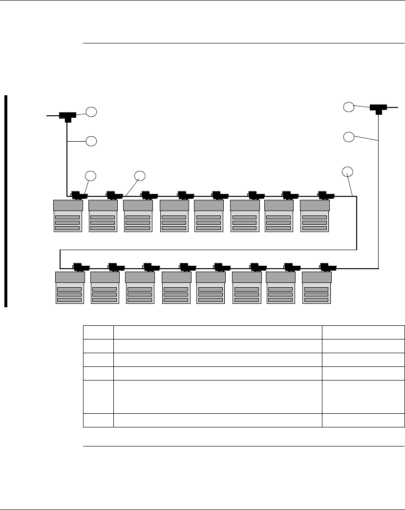
Using the Modbus Plus Ports
870 USE 101 10 V.2 189
Cluster Mode Cabling Schemes, Continued
Cluster Scheme
#1 In this example, two clusters of Momentum I/O modules are connected in
sequence. The trunk cable continues from the clusters in both directions.
Continued on next page
1
2
3 4 5
2
1
Label Description Part Number
1 Modbus Plus Tap 990 NAD 230 00
2 Modbus Plus 10 ft. Drop Cable 170 MCI 021 20
3Modbus Plus Connector “T” (DB9 base) 170 XTS 020 00
4 Modbus Plus / Modbus RS485 Short Interconnect Cable
OR
Modbus Plus / Modbus RS485 3 ft. Interconnect Cable
170 MCI 020 10
170 MCI 020 36
5 Modbus Plus / Modbus RS485 30 ft. Interconnect Cable 170 MCI 020 80
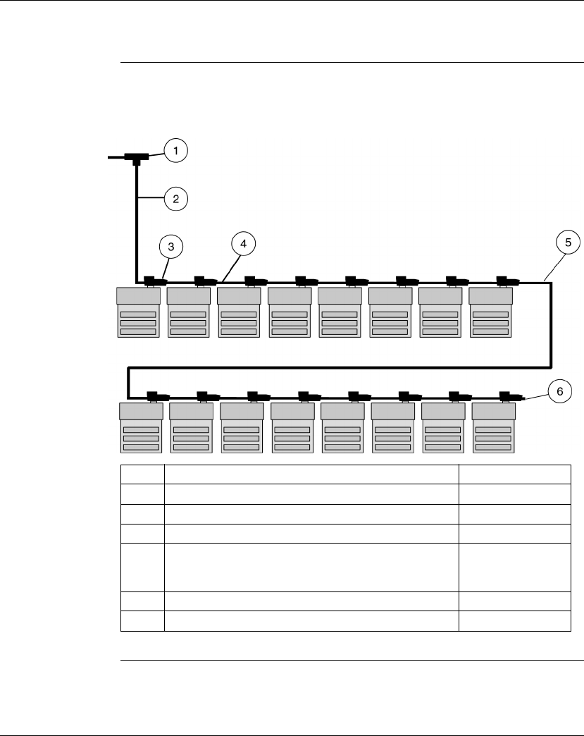
Using the Modbus Plus Ports
190 870 USE 101 10 V.2
Cluster Mode Cabling Schemes, Continued
Cluster Scheme
#2 In this example, two clusters are connected in sequence. The network ends with
the second cluster.
Label Description Part Number
1 Modbus Plus Tap 990 NAD 230 00
2 Modbus Plus 10 ft. Drop Cable 170 MCI 021 20
3Modbus Plus Connector “T” (DB9 base) 170 XTS 020 00
4 Modbus Plus / Modbus RS485 Short Interconnect Cable
OR
Modbus Plus / Modbus RS485 3 ft. Interconnect Cable
170 MCI 020 10
170 MCI 020 36
5 Modbus Plus / Modbus RS485 30 ft. Interconnect Cable 170 MCI 020 80
6 Terminating resistor plug 170 XTS 021 00

Using the Modbus Plus Ports
870 USE 101 10 V.2 191
Cable Accessories for Modbus Plus Networks
Overview This section describes the cables, connector and terminating device which should
be used in constructing a Modbus Plus network for Momentum components.
Cable Within
Clusters Cable for connecting two Modbus Plus devices within a cluster is available from
Schneider Automation in two lengths. These cables have a black boot.
Continued on next page
Description Part Number Illustration
Modbus Plus or Modbus RS485
Short Interconnect Cable (10”)
170 MCI 020 10
Modbus Plus or Modbus RS485
3 ft. Interconnect Cable
170 MCI 020 36

Using the Modbus Plus Ports
192 870 USE 101 10 V.2
Cable Accessories for Modbus Plus Networks, Continued
Cable Between
Clusters Cable for connecting two Modbus Plus clusters, or for fabricating drop cables to
and from clusters, is available from Schneider Automation in two lengths. These
cables have a black boot.
Continued on next page
Description Part Number Illustration
Modbus Plus 10 ft. Drop Cable 170 MCI 021 20
Modbus Plus or Modbus RS485
10 ft. Interconnect Cable
170 MCI 021 80
Modbus Plus or Modbus RS485
30 ft. Interconnect Cable
170 MCI 020 80
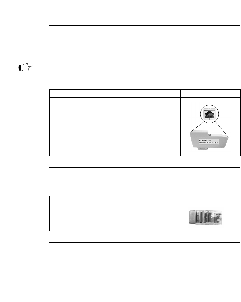
Using the Modbus Plus Ports
870 USE 101 10 V.2 193
Cable Accessories for Modbus Plus Networks, Continued
DB9 Connector
“T” This connector is used in cluster mode with a Modbus Plus Communication
Adapter or with the 172 PNN 210 22 or 172 PNN 260 22 Modbus Plus Option
Adapters.
Terminating
Resistor Plugs Terminating resistor plugs are used with the connector “T” at the last device in a
cluster when it is also the last device in the Modbus Plus network. The plug is red.
Note: Only one connector “T” may be used with each adapter, making it
impossible to use redundant cabling in cluster mode.
Description Part Number Illustration
Modbus Plus Connector “T”
(DB9 base)
170 XTS 020 00
Description Part Number Illustration
Modbus Plus or Modbus RS485
Terminating RJ45 Resistor Plugs
(pack of 2)
170 XTS 021 00
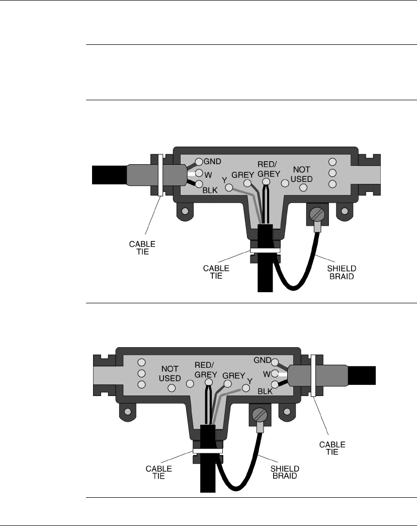
Using the Modbus Plus Ports
194 870 USE 101 10 V.2
Pinouts and Wiring Illustrations for Modbus Plus Networks
Overview This section contains pinouts and wiring illustrations for constructing an Modbus
Plus network for Momentum components.
Drop Cable from
Tap to Cluster The following illustration shows wiring an interconnect cable (with one RJ45
connector removed) from a Modbus Plus tap to a cluster:
Drop Cable from
Cluster to Tap The following illustration shows wiring an interconnect cable (with one RJ45
connector removed) from a cluster to a Modbus Plus tap:
Continued on next page
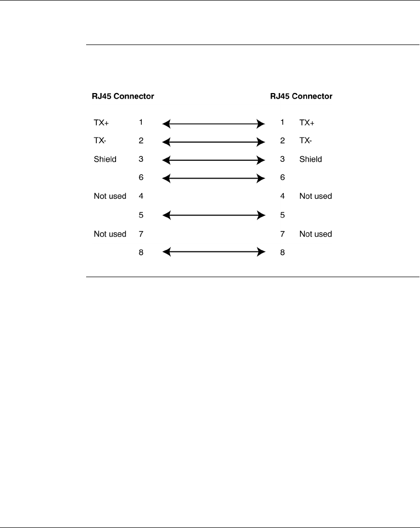
Using the Modbus Plus Ports
870 USE 101 10 V.2 195
Pinouts and Wiring Illustrations for Modbus Plus Networks, Continued
Interconnect
Cables The following illustration shows the pinout for the 170 MCI 02x xx Modbus Plus or
Modbus RS485 Interconnect Cables (10 in, 3 ft., 10 ft. and 30 ft.:
Continued on next page

Using the Modbus Plus Ports
196 870 USE 101 10 V.2
Pinouts and Wiring Illustrations for Modbus Plus Networks, Continued
Modbus Plus
Connector “T”
(DB9 Base)
The following illustration shows the pinout for the Modbus Plus Connector “T” (DB9
base):
Continued on next page
RJ45 Shielded Connector RJ45 Shielded Connector
TX+ 1
Shield 3
2 TX-
3 Shield
4
5
6
7
8
4
5
6
7
8
Shell Shell
.1 uF
500 V
12 3
DB9 Connector
1 TX+
TX- 2
TX+ TX- Shield Shell
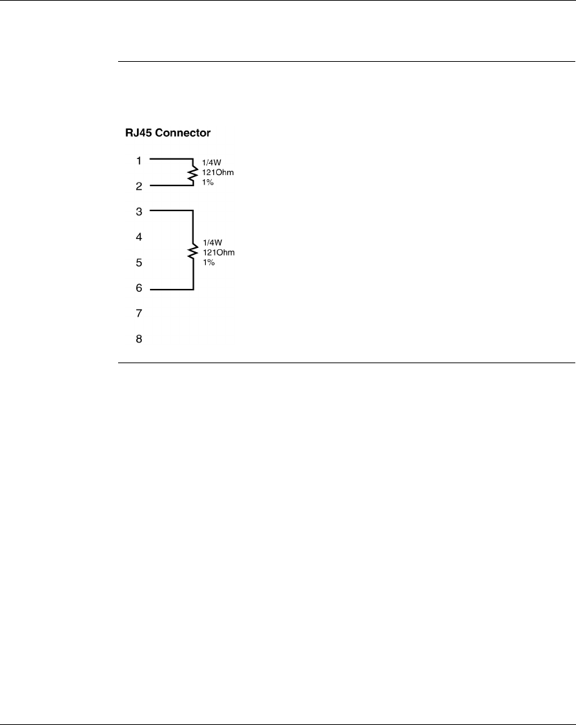
Using the Modbus Plus Ports
870 USE 101 10 V.2 197
Pinouts and Wiring Illustrations for Modbus Plus Networks, Continued
Terminating
Resistor Plugs The following illustration shows the pinout for the Modbus Plus or Modbus RS485
Terminating RJ45 Resistor Plugs:

Using the Modbus Plus Ports
198 870 USE 101 10 V.2
Modbus Plus Addresses
Introduction Modbus Plus devices function as peers on a logical ring. Each device accesses the
network by acquiring a token frame that is passed in a rotating address sequence.
Each device on a Modbus Plus network needs a unique address in the range
1...64. The device address determines the logical order in which the network token
will be passed from device to device.
Address
Sequence The assignment of addresses does not have to map to the physical layout of the
network–e.g., device 17 is placed physically before device 3. This is important to
understand because the network's token rotation is defined by device addresses-
e.g., device 2 will pass the token to device 3, device 3 to device 4, etc.
Illegal Addresses If you set the node address to 00 or to a value greater than 64:
lThe COM LED will go ON steadily to indicate an illegal address assignment.
lThe Run LED will flash 4 times.
lThe Processor Adapter will not run until you set a valid, unused address on the
Option Adapter and cycle power.
Continued on next page
CAUTION
COMMUNICATION ERRORS MAY RESULT
Do not install a Modbus Plus Option Adapter before you have set its Modbus Plus address
for your application. See your network administrator to get the Modbus Plus node address
for this module.
Failure to observe this precaution can result in injury or equipment damage.
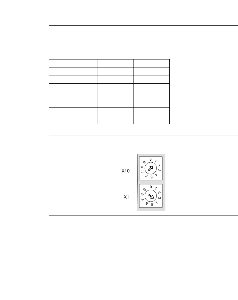
Using the Modbus Plus Ports
870 USE 101 10 V.2 199
Modbus Plus Addresses, Continued
Setting Modbus
Plus Addresses Two rotary switches on the Momentum Option Adapter are used to set the network
address. The top switch (X10) sets the upper digit (tens) of the address. The lower
switch (X1) sets the lower digit (ones) of the address.
Example of an
Address The illustration below shows a sample setting for address 14:
Node Address X10 Setting X1 Setting
1 ... 9 0 1 ... 9
10 ... 19 1 0 ... 9
20 ... 29 2 0 ... 9
30 ... 39 3 0 ... 9
40 ... 49 4 0 ... 9
50 ... 59 5 0 ... 9
60 ... 64 6 0 ... 4

Using the Modbus Plus Ports
200 870 USE 101 10 V.2
Peer Cop
What Is Peer
Cop? A Momentum M1 Processor Adapter has the ability to define point-to-point
transactions between itself and other devices on the Modbus Plus network. The
tool for defining these transactions is a panel software configuration utility known as
Peer Cop.
Configuring
Network Devices
with Peer Cop
Each device on the network can be configured to send and receive Peer Cop data.
lIn a Modbus Plus I/O networking architecture, the CPU on the network can be
used to configure the entire Peer Cop database.
lIn a Modbus Plus supervisory architecture, each CPU on the network needs to
be configured to handle the Peer Cop data that it will send or receive.
Four Types of
Data
Transactions
Peer Cop allows you to define four types of data transactions:
Sources and
Destinations Peer Cop uses defined data references (like PLC discretes or registers) as sources
and destinations. For example, a block of registers can constitute the data source
for the transmitting device, and that same or another block of registers can be the
data destination for the receiving device.
Continued on next page
Peer Cop Data
Transaction Function Maximum Data Length/Token Frame
Global Output Data to be broadcast globally
to all devices on the network
32 words
Specific Output Data to be transmitted to
individual devices
32 words/device
500 words to all specific devices
Global Input Data messages received by
all devices on the network
32 words
Specific Input Data received by a specific
device from a specific device
32 words/device
500 words from all specific devices

Using the Modbus Plus Ports
870 USE 101 10 V.2 201
Peer Cop, Continued
How Peer Cop
Data Is Sent and
Received
The reception of Peer Cop source data and the delivery of Peer Cop destination
data are handled by the token rotation. The token is always passed to the next
logical device in the network’s address sequence.
Because all the Modbus Plus devices monitor the network, any one device can
extract the data addressed specifically to it. Likewise, all devices can extract global
data. Peer Cop then enables the Modbus Plus device currently holding the token to
direct specific data to individual devices and broadcast global data to all devices on
the network as part of its token frame.
Effect of Using
Peer Cop The net effect of using Peer Cop for data transactions is that each sending device
can specify unique references as data sources and each receiving device can
specify the same or different references as data destinations. When devices
receive global data, each device can index to specific locations in the incoming
data and extract specific lengths of data from those points. Data transactions
therefore happen quickly as part of the token rotation and can be directly mapped
between data references in the sending and receiving devices.

Using the Modbus Plus Ports
202 870 USE 101 10 V.2

870 USE 101 10 V.2 203
Modsoft
At a Glance
Purpose This part describes how to configure an M1 CPU, how to I/O map an I/OBus
network, how to configure a Modbus Plus network with Peer Cop and how to save
to Flash using Modsoft 2.6.
In This Part This part contains the following chapters:
For Information On... See Chapter... See Page...
Configuring an M1 CPU with Modsoft 8 205
I/O Mapping an I/OBus Network with Modsoft 9 247
Configuring a Modbus Plus Network in Modsoft with Peer Cop 10 257
Saving to Flash in Modsoft 11 303

870 USE 101 10 V.2 205
Configuring an M1 CPU with
Modsoft
At a Glance
Introduction This chapter explains how to configure a CPU using Modsoft 2.6. The procedures
and examples described here can be applied with Modsoft Lite 2.6 as well.
In This Chapter The chapter contains the following topics.
Note: Modsoft 2.6 does not support the 171 CCC 960 20, 171 CCC 960 30, the
171 CCC 980 20 or 171 CCC 980 30 Processor Adapters. These
Processor Adapters must be configured with Concept.
For This Topic... See Section... On Page...
Configuring the Processor Adapter 1 206
Configuring Option Adapter Features 2 223
Modifying Communication Port Parameters 3 232
I/O Mapping the Local I/O Points 4 242

Configuring an M1 CPU with Modsoft
206 870 USE 101 10 V.2
Section 8.1
Configuring the Processor Adapter
Overview
Purpose This section describes how to configure a Momentum M1 Processor Adapter using
Modsoft 2.6.
In This Section This section contains the following topics:
For This Topic... See Page...
Selecting an M1 Processor Adapter 207
Specifying an M1 Processor Type 210
Default Configuration Parameters 212
Changing the Range of Discrete and Register References 215
Changing the Size of Your Application Logic Space 217
Changing the Number of Segments 218
Changing the Size of the I/O Map 220
Establishing Configuration Extension Memory 222
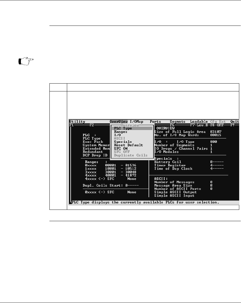
Configuring an M1 CPU with Modsoft
870 USE 101 10 V.2 207
Selecting an M1 Processor Adapter
Introduction This section describes how to select an M1 Processor Adapter with Modsoft 2.6,
starting from the Configuration Overview editor.
Procedure Follow the steps below to select an M1 Processor Adapter.
Continued on next page
Note: For a full description of how to use Modsoft 2.6, refer to
Modicon Modsoft
Programmer Software (V.2.6) User Guide
(890 USE 115 00).
Step Action
1With a new Configuration Overview editor on the screen, move the cursor onto the
OverView selection on the top menu bar.
Result: A pull-down list of options appears.
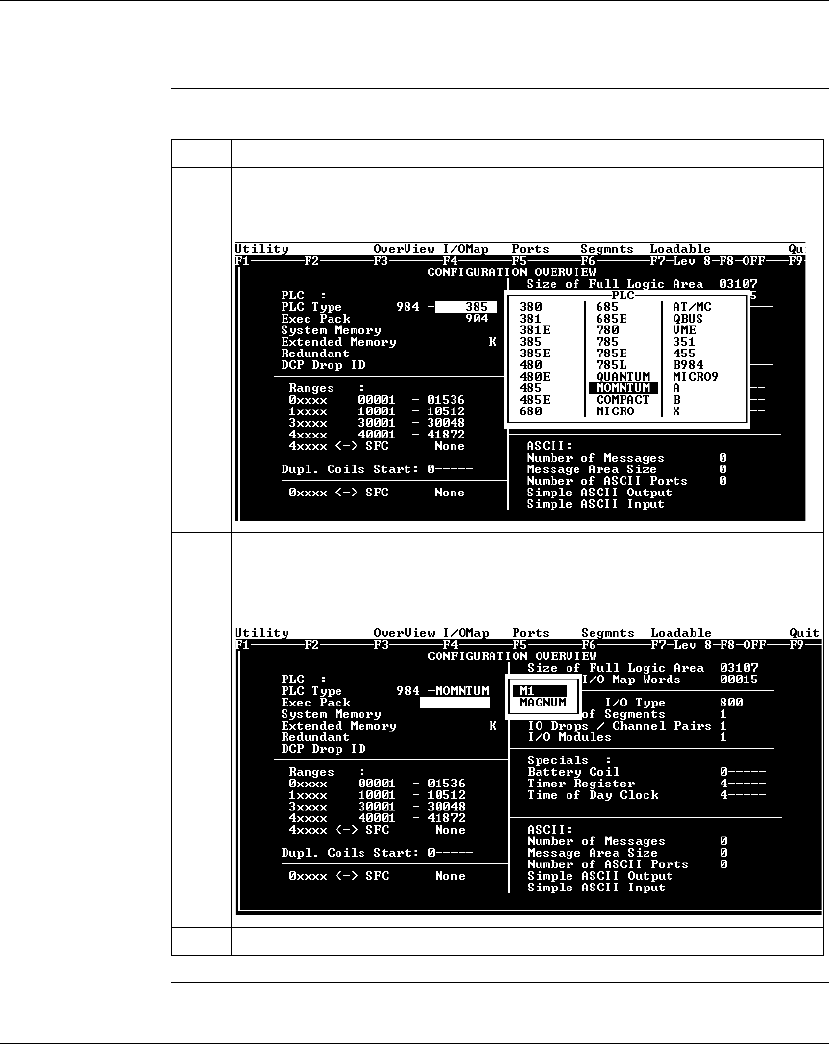
Configuring an M1 CPU with Modsoft
208 870 USE 101 10 V.2
Selecting an M1 Processor Adapter, Continued
Procedure,
Continued
Continued on next page
Step Action
2Move the cursor onto
PLC Type
in the pull-down list and push <Enter>.
Result: The following list of PLC types appears on the screen:
3Move the cursor onto MOMNTUM and push <Enter>.
Result: You will be prompted to select between the M1 Processor type and the
Magnum.
4Place the cursor on M1 and push <Enter>.
2.4K
2.4K

Configuring an M1 CPU with Modsoft
870 USE 101 10 V.2 209
Selecting an M1 Processor Adapter, Continued
Next Step You are now ready to specify the type of M1 Momentum Processor Adapter for
configuration.

Configuring an M1 CPU with Modsoft
210 870 USE 101 10 V.2
Specifying an M1 Processor Type
Introduction Once you have selected an M1 Processor Adapter in Modsoft 2.6, you must
choose between three types of M1 processors.
lA 2.4K machine
lA 12.0K machine
lAn 18.0K machine
These numbers refer to the amount of user memory in the CPU.
Which Type
Should I
Choose?
Use the table below to determine which processor type to choose:
If You Choose
the Wrong Type If you choose the wrong machine type for the CPU you are configuring, you can run
into the following kinds of problems:
lIf you specify too much memory, Modsoft allows you to create a configuration
and logic program that could be too big for the CPU you are using. When you
try to transfer your program to the CPU, your transfer will fail.
lIf you specify too little memory, Modsoft restricts the size of your configuration
and logic program, and may not allow you to I/O Map an I/OBus network (as
described in
I/O Mapping an I/OBus Network with Modsoft
on page 247).
Continued on next page
Processor Adapter Type
171 CCS 700 00 2.4
171 CCS 700 10 2.4
171 CCS 760 00 12.0
171 CCC 760 10 18.0
171 CCS 780 00 2.4
171 CCC 780 10 18.0
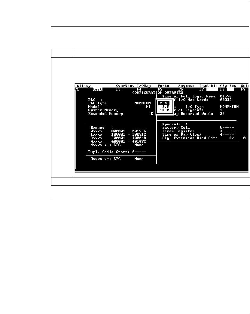
Configuring an M1 CPU with Modsoft
870 USE 101 10 V.2 211
Specifying an M1 Processor Type, Continued
Procedure Follow the steps below to specify an M1 Processor Type.
Step Action
1As a result of selecting an M1 Processor Adapter, you will be presented with a
pop-up screen that allows you to select the machine type. Move the cursor onto
the desired memory size (2.4, 12.0 or 18.0).
2Push <Enter>.
2.4K
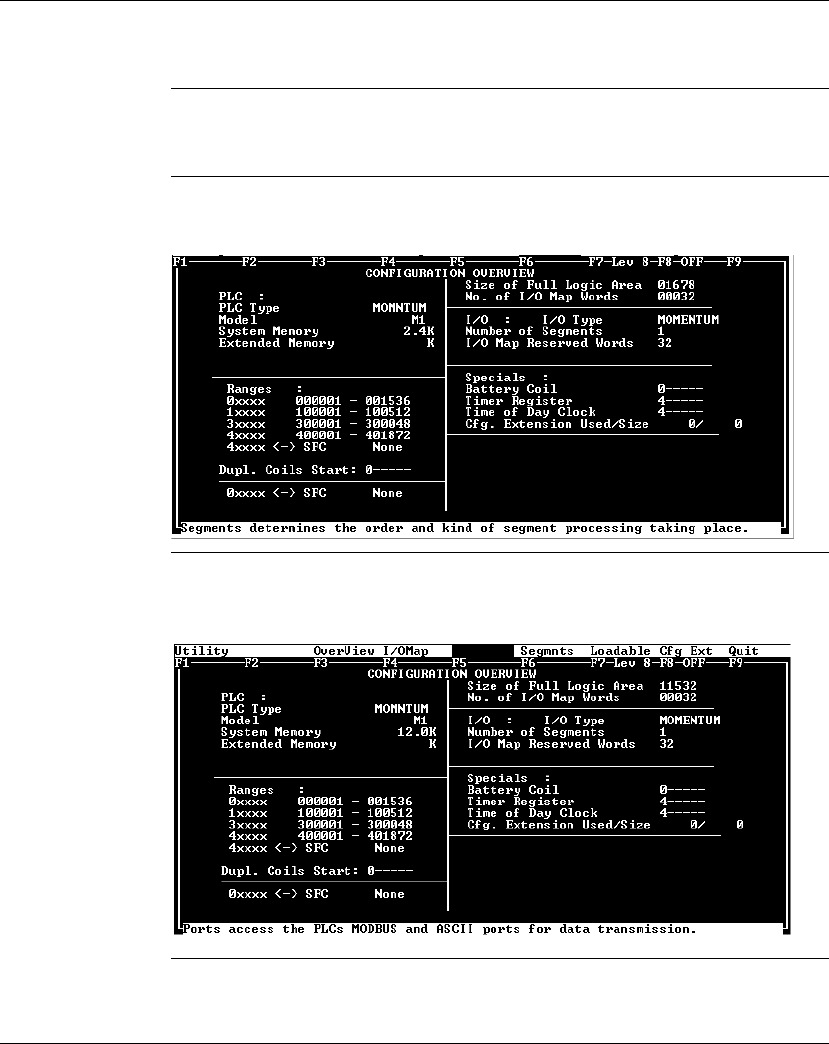
Configuring an M1 CPU with Modsoft
212 870 USE 101 10 V.2
Default Configuration Parameters
Overview This section describes the default configuration parameters.
Defaults for a
2.4K Adapter This sample Configuration Overview screen shows the default configuration
parameters.
Defaults for a
12.0K Adapter This sample Configuration Overview screen shows the default configuration
parameters:
Continued on next page
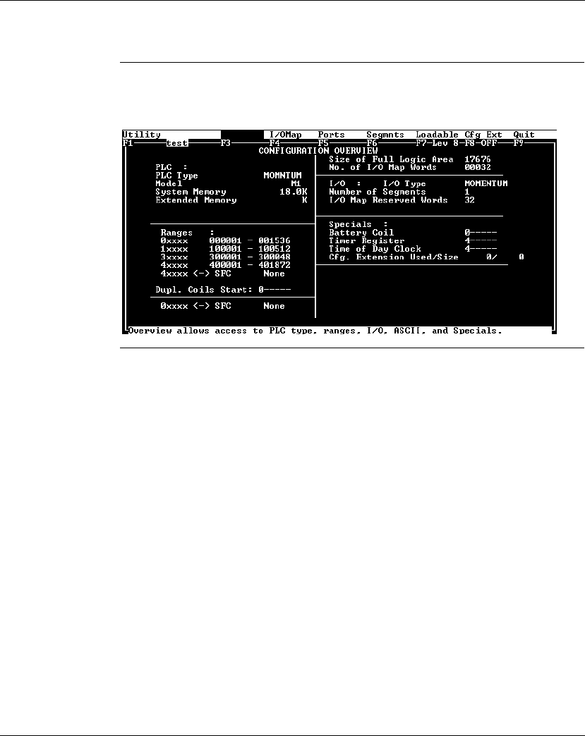
Configuring an M1 CPU with Modsoft
870 USE 101 10 V.2 213
Default Configuration Parameters, Continued
Defaults for an
18.0 Adapter This sample Configuration Overview screen shows the default configuration
parameters:
Continued on next page

Configuring an M1 CPU with Modsoft
214 870 USE 101 10 V.2
Default Configuration Parameters, Continued
Default Values Here are the default parameters:
Parameter 2.4K Adapter 12.0K Adapter 18.0K Adapter
Coils in state RAM 1536 (0
x
) 1536 (0
x
) 1536 (0
x
)
Discrete inputs in state
RAM
512 (1
x
) 512 (1
x
) 512 (1
x
)
Input registers in state
RAM
48 (3
x
) 48 (3
x
) 48 (3
x
)
Output registers in state
RAM
1872 (4
x
) 1872 (4
x
) 1872 (4
x
)
Bytes of user memory
space available for
application logic
1678 13100 17676
Words of user memory
space for the I/O Map
32 512 32
I/O logic segments One, which will
allow you to I/O
Map the I/O points
on the local base
unit
One, which will
allow you to I/O
Map the I/O points
on the local base
unit
One, which will
allow you to I/O
Map the I/O points
on the local base
unit
Memory allocated for
configuration extension
None None None

Configuring an M1 CPU with Modsoft
870 USE 101 10 V.2 215
Changing the Range of Discrete and Register References
Introduction This section provides guidelines and a procedure for changing the range of discrete
(0
x
and 1
x
) and register (3
x
and 4
x
) references.
Guidelines When you change the range of discrete and register references, follow these
guidelines:
lAdjust the range of discretes in increments of 16. Sixteen discretes consume
one word.
lAdjust the range of registers in increments of 1. Each register consumes one
word.
lThe total number of register and discrete references cannot exceed 3k words.
lA minimum configuration of 16 0
x
discretes, 16 1
x
discretes, one 3
x
register,
and one 4
x
register is required.
Continued on next page
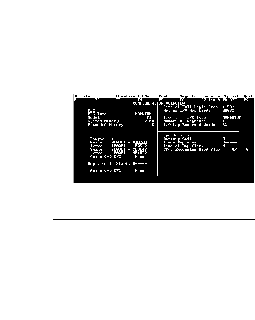
Configuring an M1 CPU with Modsoft
216 870 USE 101 10 V.2
Changing the Range of Discrete and Register References, Continued
Procedure From the Configuration Overview screen, follow the steps below to change the
range of discrete and register references:
Step Action
1From the Overview menu, select Ranges.
Result: The cursor will appear in the Ranges field of the editor on the high range
0
x
value.
2Modify the range of your discrete and register references by changing the high
value, in keeping with the guidelines described above. Press <Enter> after
completing each field.

Configuring an M1 CPU with Modsoft
870 USE 101 10 V.2 217
Changing the Size of Your Application Logic Space
Introduction The number shown in the Size of Full Logic Area field in the Configuration
Overview screen indicates the total amount of memory available for your
application logic. You cannot directly enter this field to modify the value. You can,
however, change the amount of memory available by manipulating the size of other
fields in the Configuration Overview screen.
Example 1 If you reduce the size of the I/O Map area, the number in the Full Logic Area field
automatically increases. Say you are using a 12.0K machine and you change the
size of the I/O Map from the default value of 512 to 256–a decrease of 256 words.
The default Size of Full Logic Area will automatically increase from 1198 to 1454.
Example 2 Similarly, if you allocate some number of words to configuration extension memory
(to support Peer Cop), you will reduce the Size of Full Logic Area by the number of
words allocated the configuration extension memory.

Configuring an M1 CPU with Modsoft
218 870 USE 101 10 V.2
Changing the Number of Segments
Introduction The number of segments specified in the Configuration Overview screen
determines the number of I/O Map drops that you will be able to set up for your
CPU.
The number of segments you will need depends on whether your Processor
Adapter will support an I/OBus network.
For I/OBus
Networks You must change the number of segments to 2 if you want to create an I/O Map to
support an I/OBus network.
For All Other
Cases The default number of segments (1) is correct. You only need one drop because
the only points to be I/O Mapped are those on the local base.
Continued on next page
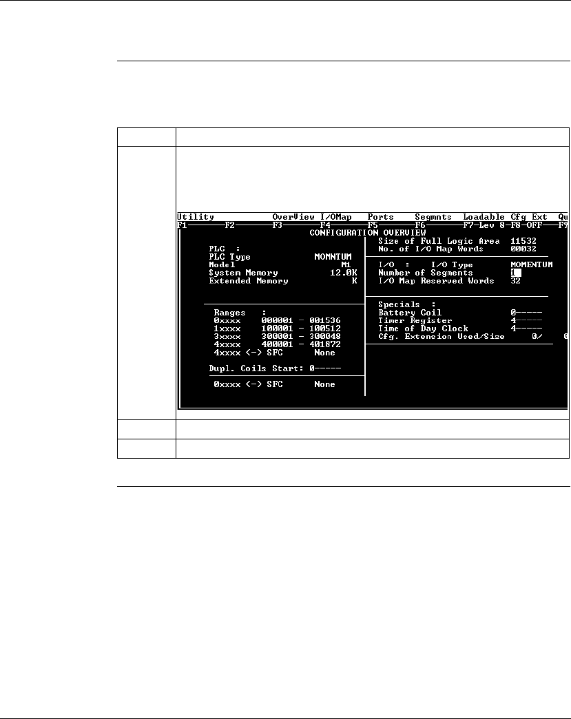
Configuring an M1 CPU with Modsoft
870 USE 101 10 V.2 219
Changing the Number of Segments, Continued
Procedure From the Configuration Overview screen, follow the steps below to change the
number of segments:
Step Action
1From the Overview menu, select I/O.
Result: The cursor will appear in the I/O field of the editor on the number of
segments.
2Type the new number of segments.
3Push <Enter>.

Configuring an M1 CPU with Modsoft
220 870 USE 101 10 V.2
Changing the Size of the I/O Map
Introduction The default size of the I/O Map and your options vary, depending on whether or not
your Processor Adapter supports an I/OBus network.
Processors For
I/O Bus
Networks
With I/OBus, an I/O Map table is used to define the number, location, and type of
I/O devices on the network bus.
All Other
Processors Other Processor Adapters only use the I/O Map for local I/O. The default of 32
words is sufficient for any Momentum I/O base. Depending on the requirements of
your I/O base, you may be able to reduce the number of words to the minimum, 17,
in order to increase the size of the full logic area.
Continued on next page
Default 512 words
Minimum 17 words
Default 32 words
Minimum 17 words
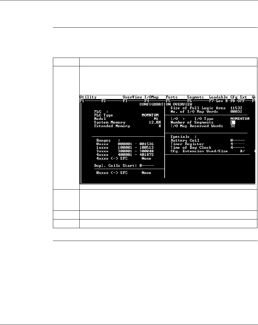
Configuring an M1 CPU with Modsoft
870 USE 101 10 V.2 221
Changing the Size of the I/O Map, Continued
Procedure From the Configuration Overview screen, follow the steps below to change the size
of the I/O Map:
Step Action
1From the Overview menu, select I/O.
Result: The cursor will appear in the I/O field of the editor on the number of
segments.
2Push <Enter>.
Result: The cursor moves to the I/O Map Reserved Words field.
3Modify the I/O Map size by typing a new number in this field.
4Push <Enter>.

Configuring an M1 CPU with Modsoft
222 870 USE 101 10 V.2
Establishing Configuration Extension Memory
Introduction By default, no memory space is allocated for configuration extension memory. If
you want to use the Peer Cop capability to handle Modbus Plus communications,
you need to define some configuration extension memory to enable Peer Cop.
Extension memory is specified as a number of 16-bit words. That number is
entered in the ExtSize entry of the Configuration editor. Once an adequate
number of words has been specified here, Peer Cop will be enabled in the CfgExt
pull-down list.
How Much
Memory? The minimum Peer Cop ExtSize memory requirement is 20 words; the maximum
is 1366 words.
Follow these guidelines for estimating the amount of extension memory you will
need for your Peer Cop database:
Procedure From the Configuration Overview screen, follow the steps below to establish
configuration extension memory:
For... Add... Up to a maximum of...
Overhead 9 words --
Global output 5 words --
Global input number of words=
number of devices x
(1 + 2 x number of device subentries)
1088 words
Specific output 2 words for every device entry in Peer Cop 128 words
Specific input 2 words for every device entry in Peer Cop 128 words
Step Action
1 From the Cfg Ext menu, select Cfg. Extension Size.
Result: The cursor will appear in the Cfg. Extension Used/Size entry.
2 Type the desired size.
3 Push <Enter>.

Configuring an M1 CPU with Modsoft
870 USE 101 10 V.2 223
Section 8.2
Configuring Option Adapter Features
Overview
Purpose This section describes how to implement the battery backup and time-of-day (TOD)
clock features of the Momentum Option Adapters.
In This Section This section contains the following topics:
For This Topic... See Page...
Reserving and Monitoring a Battery Coil 224
Setting up the Time-of-Day Clock 226
Setting the Time 228
Reading the Time-of-Day Clock 231
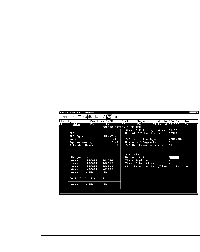
Configuring an M1 CPU with Modsoft
224 870 USE 101 10 V.2
Reserving and Monitoring a Battery Coil
Introduction Since the Option Adapter does not have an LED to indicate when the battery is low,
we recommend that you reserve a 0
x
reference to monitor the health of the battery.
This section describes how to reserve and monitor a battery coil, using the
Configuration Overview editor in Modsoft 2.6.
Reserving a
Battery Coil To reserve a battery coil, perform the steps in the following table.
Continued on next page
Step Action
1From the Overview menu, select Specials.
Result: The cursor moves into the Battery Coil field on the Configuration
Overview screen.
2Enter a coil number in the range of available 0
xxxx
references.
Example: If you have set the range of 0
x
’s at 000001...001536, you might want to
enter the reference value of the last coil–1536.
3Push <Enter>.

Configuring an M1 CPU with Modsoft
870 USE 101 10 V.2 225
Reserving and Monitoring a Battery Coil, Continued
Monitoring the
Battery Coil Monitor the battery coil in ladder logic or tie it to a lamp or alarm that will indicate
when the battery is low.
Interpreting the
Battery Coil The battery coil will always read either 0 or 1.
lA coil state of 0 indicates that the battery is healthy.
lA coil state of 1 indicates that the battery should be changed.
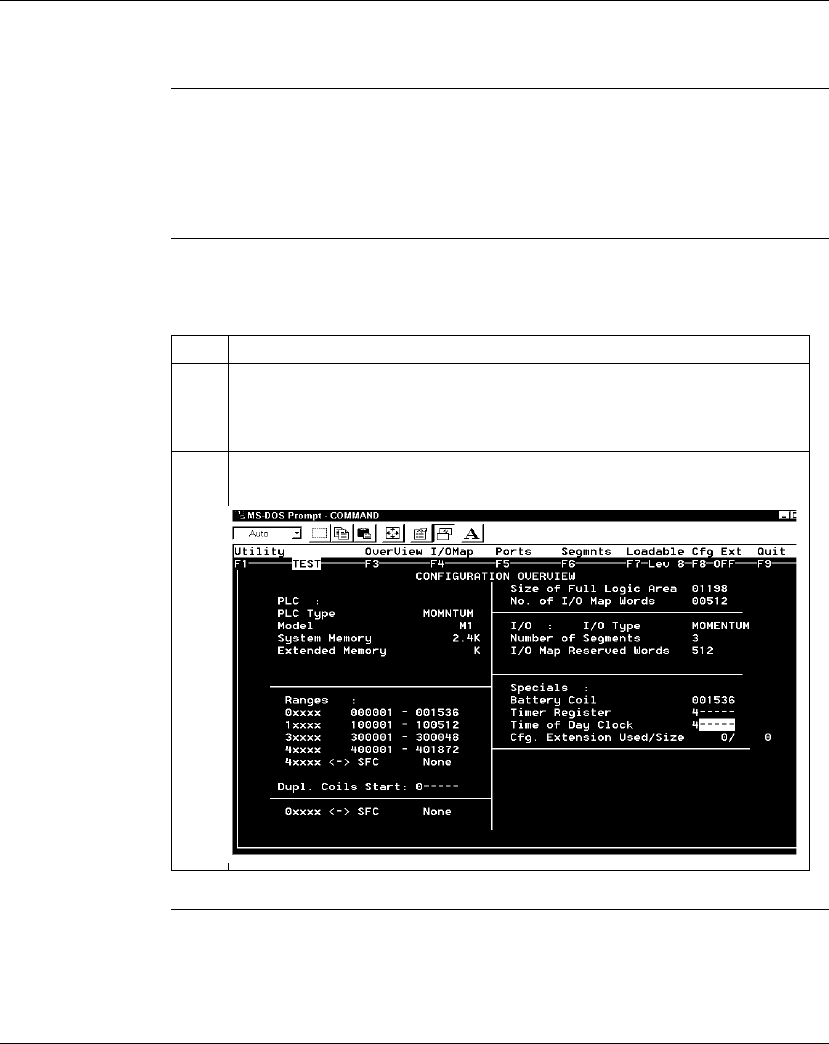
Configuring an M1 CPU with Modsoft
226 870 USE 101 10 V.2
Setting up the Time-of-Day Clock
Overview Each Option Adapter has a time-of-day clock. To use this feature, you must reserve
a block of eight 4
x
registers.
This section describes how to reserve those registers, using Modsoft 2.6.
Reserving
Registers for the
TOD Clock
To reserve registers for the time-of-day clock, perform the steps in the following
table.
Continued on next page
Step Action
1From the Overview menu, select Specials.
Result: The cursor moves into the Battery Coil field on the Configuration
Overview screen.
2Push the down arrow key twice to move the cursor into the Time of Day Clock
field.
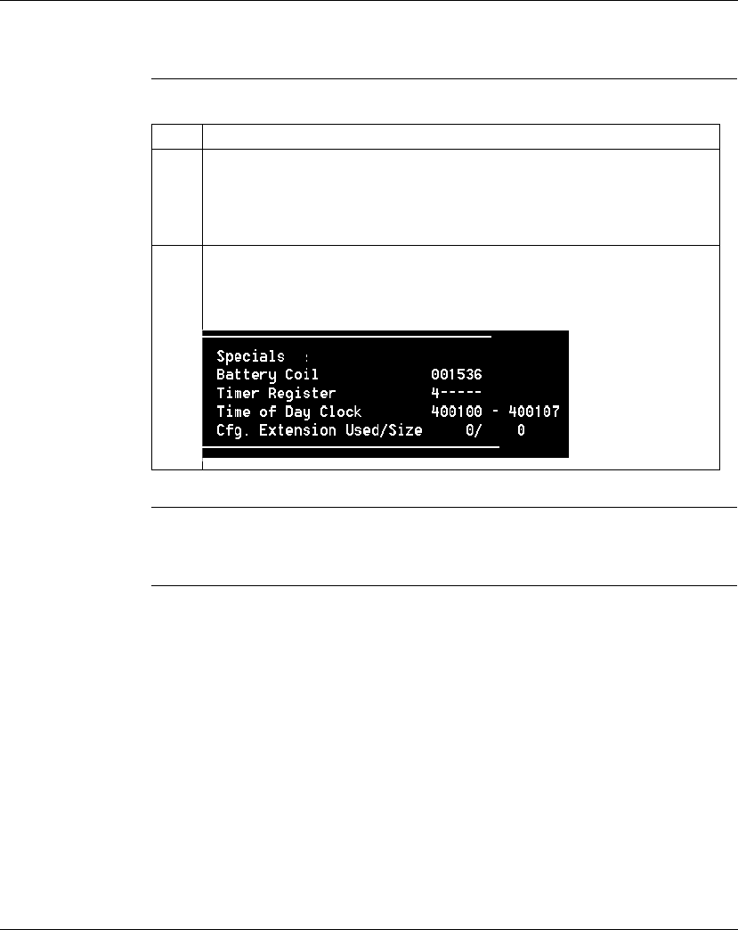
Configuring an M1 CPU with Modsoft
870 USE 101 10 V.2 227
Setting up the Time-of-Day Clock, Continued
Reserving
Registers for the
TOD Clock,
Continued
Next Step Setting the time.
Step Action
3Enter a number (the first in a series of eight) in the range of available 4
xxxx
references.
Example: If you want registers 400100...400107 reserved for the TOD clock,
enter 100.
4Push <Enter>.
Result: The reference value you specified and the seven that follow it are now
reserved for TOD clock data.

Configuring an M1 CPU with Modsoft
228 870 USE 101 10 V.2
Setting the Time
Overview Once you have reserved a block of registers for the time-of-day clock, you have to
set the correct time. Modsoft offers two ways to do this:
lusing the Set Hardware Clock dialogue
lsetting the register bits individually
Option 1 You must be online or in combined mode to access the Set Hardware Clock
dialogue.
Continued on next page
Note: The time-of-day clock complies with guidelines for the year 2000.
Step Action
1From the PlcOps menu, select Set Hardware Clock.
Result: The Set Hardware Clock dialogue appears.
2You may set the time directly or copy the current time setting from your
programming panel.
To set the time directly, proceed to step 3.
To copy the setting from your programming panel, proceed to step 4.
3The time setting for your programming panel is displayed on the left. The
controller time setting is displayed on the right. The time is expressed as
hh:mm:ss. The date is expressed as mm-dd-yy.
To modify the settings, type a new value in the date or time field for the
controller.
To confirm the default settings or your modified settings, press <Enter>.
4To copy the current time setting from your programming panel, type Y in response
to the question: Write PANEL clock data to PLC? (Y/N). Then
press <Enter>.

Configuring an M1 CPU with Modsoft
870 USE 101 10 V.2 229
Setting the Time, Continued
Option 2 Go online and set the register values individually, using the following guidelines and
procedure for setting the status bits and setting the time bits. The CPU must be
running while you are setting the bits.
Setting the
Status Bits The control register (4
x
) uses its four most significant bits to report status:
Setting the Time
Bits The following table shows how the registers handle time-of-day clock data, where
register 4
x
is the first register in the block reserved for the clock:
Continued on next page
Control Register
1514131211109876543210
1 = error
1 = All clock values have been set
1 = Clock values are being read
1 = Clock values are being set
Register Data Content
4
x
The control register
4
x
+ 1 Day of the week (Sunday = 1, Monday = 2, etc.)
4
x
+ 2 Month of the year (Jan = 1, Feb = 2, etc.)
4
x
+ 3 Day of the month (1...31)
4
x
+ 4 Year (00...99)
4
x
+ 5 Hour in military time (0...23)
4
x
+ 6 Minute (0...59)
4
x
+ 7 Second (0...59)

Configuring an M1 CPU with Modsoft
230 870 USE 101 10 V.2
Setting the Time, Continued
Procedure Follow the steps in the table below to set the register values for the time-of-day
clock:
Step Action
1Set the correct date and time in registers 4
x
+ 1 through 4
x
+ 7.
Example: To set the clock for Thursday, April 9, 1998 at 4:17:00, set the following
values in the registers:
4
x
+ 1 5
4
x
+ 2 4
4
x
+ 3 9
4
x
+ 4 98
4
x
+ 5 4
4
x
+ 6 17
4
x
+ 7 00
2Load the value 8000H in register 4
x
to write the data to the clock.

Configuring an M1 CPU with Modsoft
870 USE 101 10 V.2 231
Reading the Time-of-Day Clock
Overview This section tells how to read the time-of-day clock and uses an example to
describe how to interpret the time-of-day clock registers.
Reading the
Clock Set the value 4000H in register 4x to read data from the clock.
Example If you reserved registers 400100...400107 as your TOD clock registers, set the time
bits, and then read the clock at 9:25:30 on Thursday, July 16, 1998, the registers
would display the following values:
Register Reading Indication
400100 0 1 1 0 0 0 0 0 0 0 0 0 0 0 0 0 All clock values have been set;
clock values are being read
400101 5 (decimal) Thursday
400102 7 (decimal) July
400103 16 (decimal) 16
400104 98 (decimal) 1998
400105 9 (decimal) 9 a.m.
40010 6 25 (decimal) 25 minutes
40010 7 30 (decimal) 30 seconds

Configuring an M1 CPU with Modsoft
232 870 USE 101 10 V.2
Section 8.3
Modifying Communication Port Parameters
Overview
Purpose The communication parameters on the Modbus ports are set at the factory. This
section describes how to access the Port editor and how to edit the default
parameters.
In This Section This section contains the following topics.
For This Topic... See Page...
Accessing the Port Editor Screen 233
Parameters Which Should Not Be Changed 234
Changing the Mode and Data Bits 235
Changing Parity 237
Changing the Baud Rate 238
Changing the Modbus Address 239
Changing the Delay 240
Changing the Protocol on Modbus Port 2 241
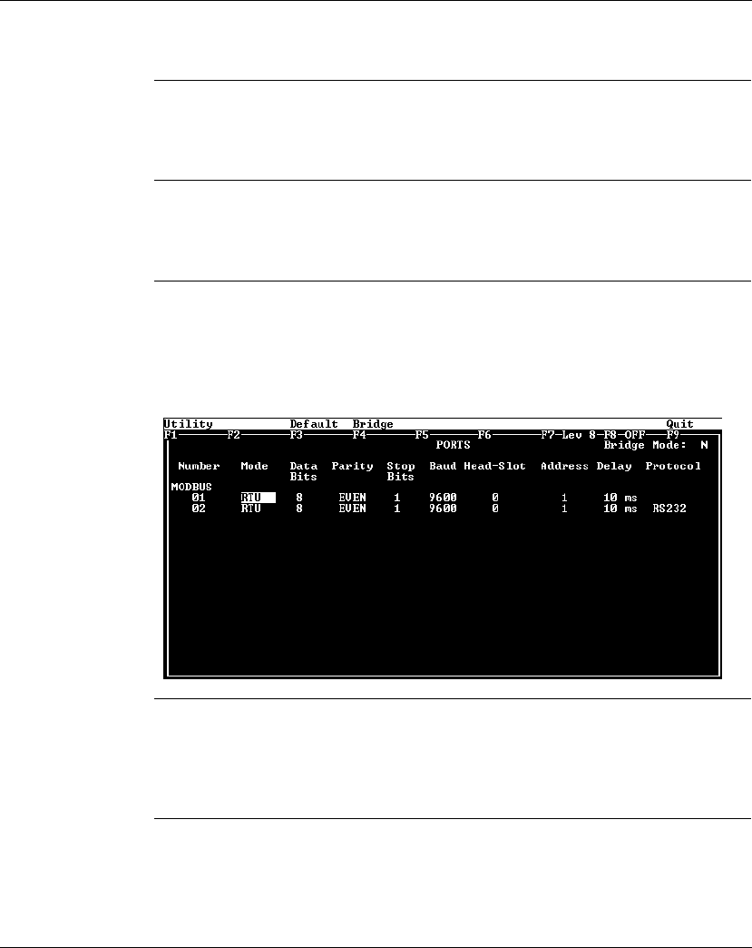
Configuring an M1 CPU with Modsoft
870 USE 101 10 V.2 233
Accessing the Port Editor Screen
Introduction Modbus port parameters can be modified using the Port editor in Modsoft 2.6. This
screen is accessed from the Configuration Overview editor.
How To Get
There To access the Port editor from the Configuration Overview editor, move the cursor
onto the Ports selection on the top menu bar, then push <Enter>.
Port Editor
Showing Default
Values
If you have not previously modified any port parameters, the following screen will
appear. The screen shows the default parameters for two Modbus ports, 01 and 02.
If you have previously modified any communication port parameters, the new
values will appear in the screen.
Two Sets of
Parameters This screen will always show two sets of port parameters, even if your particular
CPU configuration supports only Modbus Port 1. In that case, ignore any parameter
values shown for Port 2.

Configuring an M1 CPU with Modsoft
234 870 USE 101 10 V.2
Parameters Which Should Not Be Changed
Overview Two parameters on the Port editor screen should not be changed. These are the
stop bit and head-slot parameters.
Stop Bit Each port operates only with 1 stop bit. While Modsoft will allow you to select 2 stop
bits, this setting is invalid.
Head-Slot The Head-Slot parameter is set to 0 and should be left at this value for the
Momentum M1 CPUs.
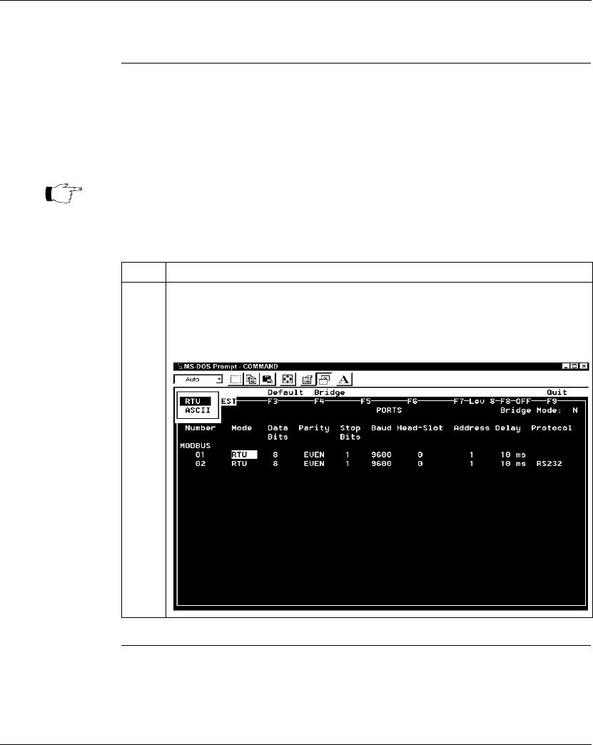
Configuring an M1 CPU with Modsoft
870 USE 101 10 V.2 235
Changing the Mode and Data Bits
Introduction From the Port editor screen, each port can be configured to operate in one of two
possible modes – RTU or ASCII.
lIf the mode is RTU, the number of data bits is always 8.
lIf the mode is ASCII, the number of data bits is always 7.
Procedure To change the mode and data bit parameters, perform the steps in the following
table.
Continued on next page
Note: The factory-set default is 8-bit RTU.
Step Action
1Place the cursor on the current Mode entry for the Modbus port you want to enter.
Push <Enter>.
Result: A popup window appears in the top left corner of the screen displaying your
two Mode options:
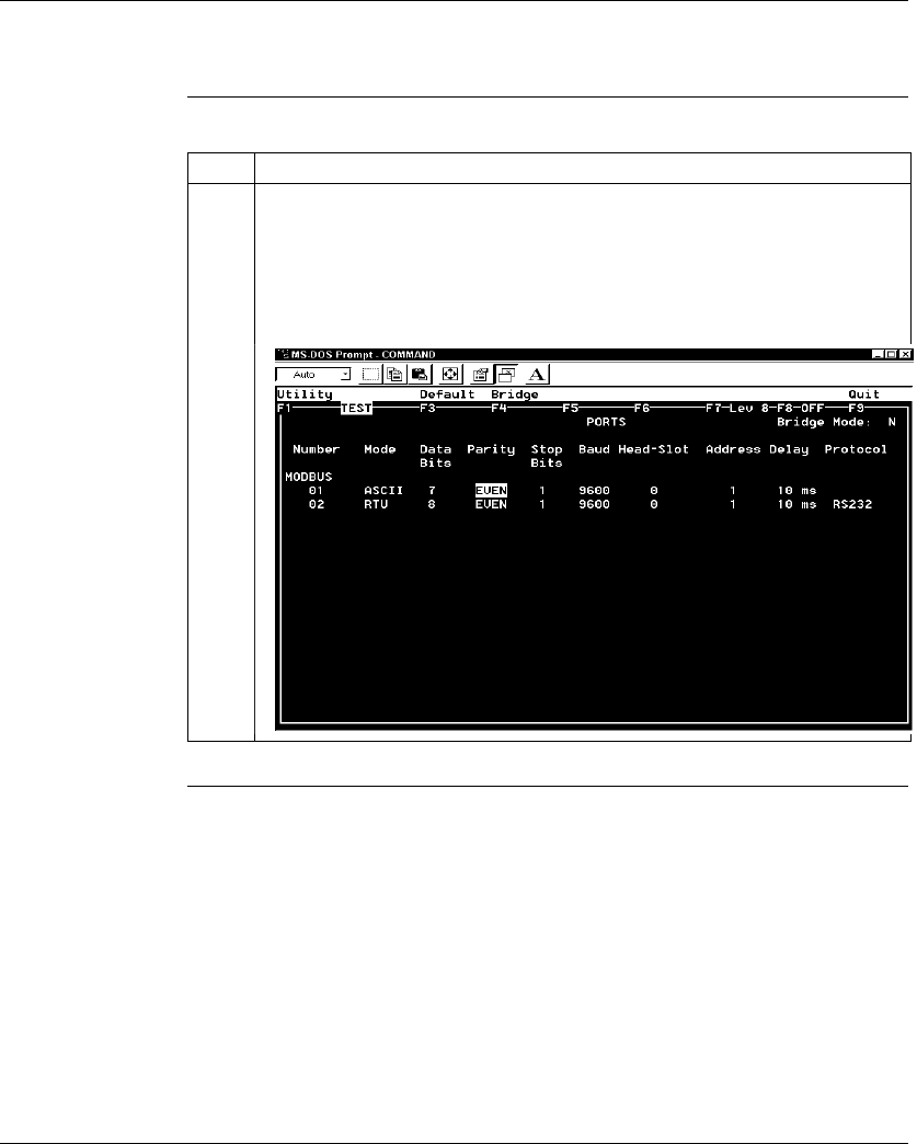
Configuring an M1 CPU with Modsoft
236 870 USE 101 10 V.2
Changing the Mode and Data Bits, Continued
Procedure,
Continued Step Action
2Use an arrow key to toggle the cursor onto the desired Mode selection in the popup
window, then push <Enter>.
Result: The Port editor screen is updated with the Mode type you have specified,
the corresponding Data Bit value appears, and the cursor moves to the Parity
column. For example, if you change Modbus port 1 from RTU mode to ASCII mode,
the Data Bit value also automatically changes from 8 to 7, as shown below:
6
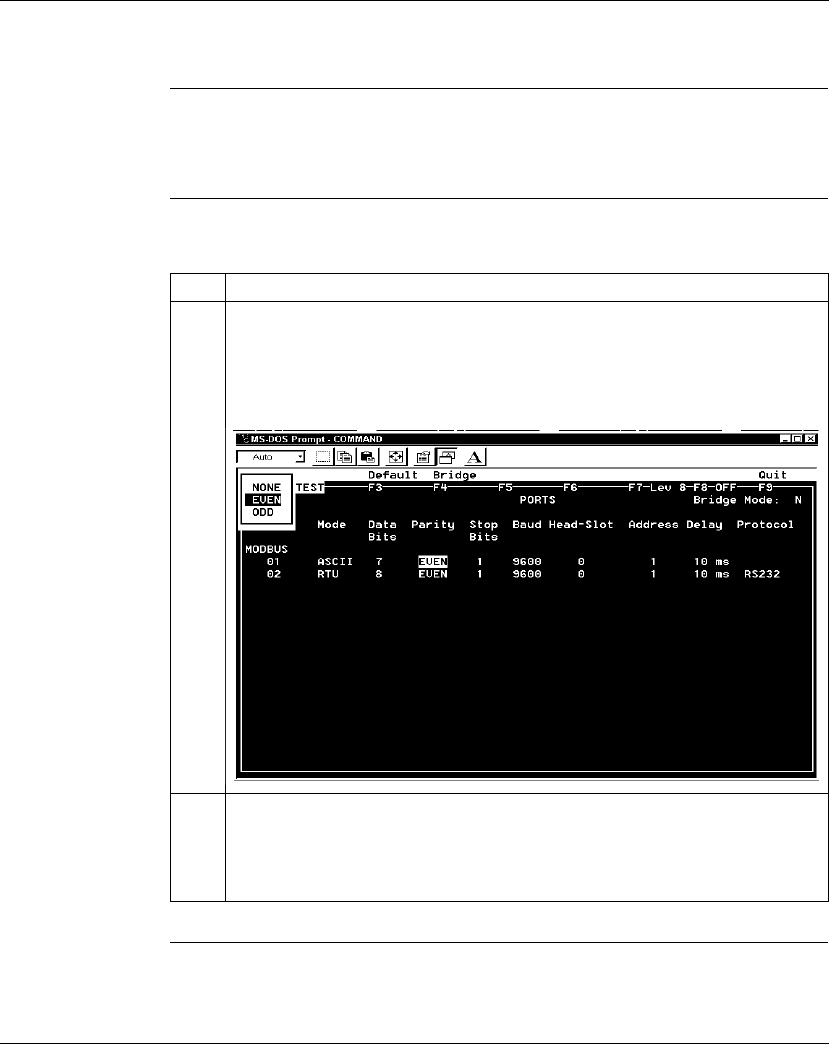
Configuring an M1 CPU with Modsoft
870 USE 101 10 V.2 237
Changing Parity
Introduction From the Port editor screen, a port can be configured for even, odd, or no parity
checking. The factory-set default is EVEN parity.
Procedure To change the parity parameter, perform the steps in the following table.
Step Action
1Place the cursor on the current Parity entry for the Modbus port you want to enter.
Push <Enter>.
Result: A popup window appears in the top left corner of the screen displaying your
three Parity options:
2Use an arrow key to toggle the cursor onto the desired Parity selection in the popup
window, then push <Enter>.
Result: The Port editor screen is updated with the Parity type you have specified,
and the cursor moves to the Stop Bits column.
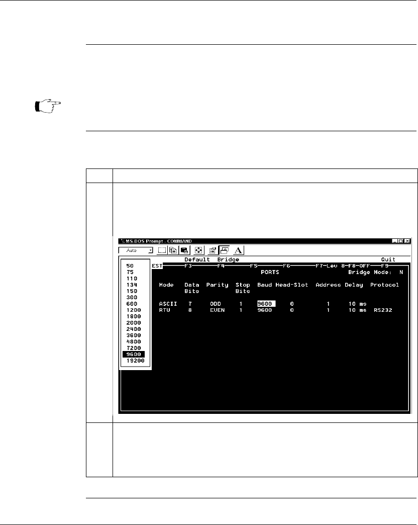
Configuring an M1 CPU with Modsoft
238 870 USE 101 10 V.2
Changing the Baud Rate
Overview Each port can be configured for a baud in the range 50...19,200. Sixteen valid
bauds are user-selectable. The factory-set default is 9600 baud.
Procedure To change the baud parameter, perform the steps in the following table.
Note: If you use a baud rate lower than 4800, you should adjust the default
delay parameter. See
Changing the Delay
on page 240.
Step Action
1Place the cursor on the current Baud entry for the Modbus port you want to enter.
Push <Enter>.
Result: A popup window appears in the top left corner of the screen displaying 16
baud values:
2Use an arrow key to toggle the cursor onto the desired Baud selection in the popup
window, then push <Enter>.
Result: The Port editor screen is updated with the Baud number you have specified,
and the cursor moves to the Head-Slot column.

Configuring an M1 CPU with Modsoft
870 USE 101 10 V.2 239
Changing the Modbus Address
Overview Each port can be assigned a Modbus network address in the range 1...247. That
address must be unique with respect to all other device addresses on the same
Modbus networks.
Since Modbus Port 1 and Modbus Port 2 are always on different Modbus networks,
they can both be assigned the same address value without conflict. The factory-set
default for both ports is address 1.
Procedure From the Port editor screen, perform the steps in the following table to change the
Modbus Address:
Step Action
1Place the cursor on the current Address entry for the Modbus port.
2Type a number in the range 1...247. Push <Enter>.
Result: The Port editor screen is updated with the Address number you have
typed, and the cursor moves to the Delay column.

Configuring an M1 CPU with Modsoft
240 870 USE 101 10 V.2
Changing the Delay
Overview The default value for the delay parameter is 10 ms. This value is appropriate for
most Momentum applications.
However, if you use baud rates lower than 4800, you should adjust the delay
timing.
Delay Timing If you use baud rates lower than 4800, adjust the delay timing as indicated in the
following table:
Valid Delay
Values The delay must always be a value between 10 and 200 ms, expressed in 10 ms
increments.
Procedure From the Port editor screen, perform the steps in the following table to change the
Delay parameter:
Baud Rate Delay (in Msec)
2400 20
1200 30
600 50
300 100
Step Action
1Place the cursor on the current Delay entry for the Modbus port.
2Type a new value in the range 10 ... 200 ms, using 10 ms increments. Push
<Enter>.
Result: The Port editor screen is updated with the Delay you have specified.
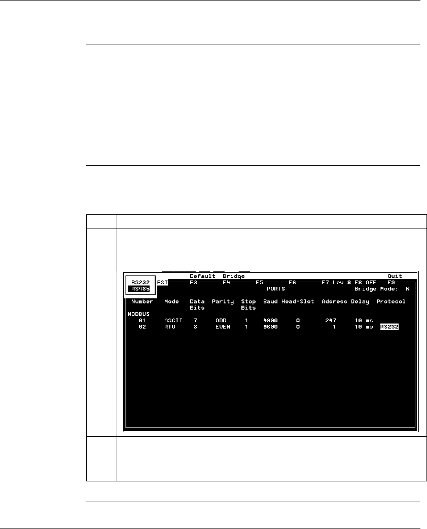
Configuring an M1 CPU with Modsoft
870 USE 101 10 V.2 241
Changing the Protocol on Modbus Port 2
Overview If your Momentum M1 CPU is using the Modbus Port 2 provided by the 172 JNN
210 32 Option Adapter, you can specify whether it will use the RS232 or RS485
protocol. The factory-set default for Modbus Port 2 is RS232.
If you are using the Modbus Port 2 provided on the 171 CCS 780 00 or
171 CCC 780 10 Processor Adapter, the port is hardwired as a dedicated RS485
protocol. However, you must change the default setting on the Port editor screen
from RS232 to RS485, or the port will not function.
Procedure From the Port editor screen, perform the steps in the following table to change the
Protocol on Modbus Port 2.
Step Action
1Place the cursor on the current Protocol entry for Modbus port 2. Push <Enter>.
Result: A popup window appears in the top left corner of the screen displaying the
two protocol options:
2Use an arrow key to toggle the cursor onto the desired protocol selection in the
popup window, then push <Enter>.
Result: The Port editor screen is updated with the protocol you have specified.

Configuring an M1 CPU with Modsoft
242 870 USE 101 10 V.2
Section 8.4
I/O Mapping the Local I/O Points
Accessing and Editing the I/O Map
Introduction Every M1 Processor Adapter is assembled on an I/O base. The I/O points on the
base are the local I/O for that processor.
As part of the configuration process, you need to create an I/O Map for the local
I/O. The I/O Map assigns the appropriate range and type of (0
x
, 1
x
, 3
x
, or 4
x
)
reference values from the CPU’s state RAM to the input and/or output points on the
local base unit.
Accessing an I/O
Map Screen To access an I/O Map screen from the Configuration Overview screen, move the
cursor onto the I/O Map command on the top menu and push <Enter>.
Result: An I/O Map screen appears with the cursor placed in the Module field. The
label in the top left corner of the screen identifies it as Type: MOMENTUM I/O.
Continued on next page
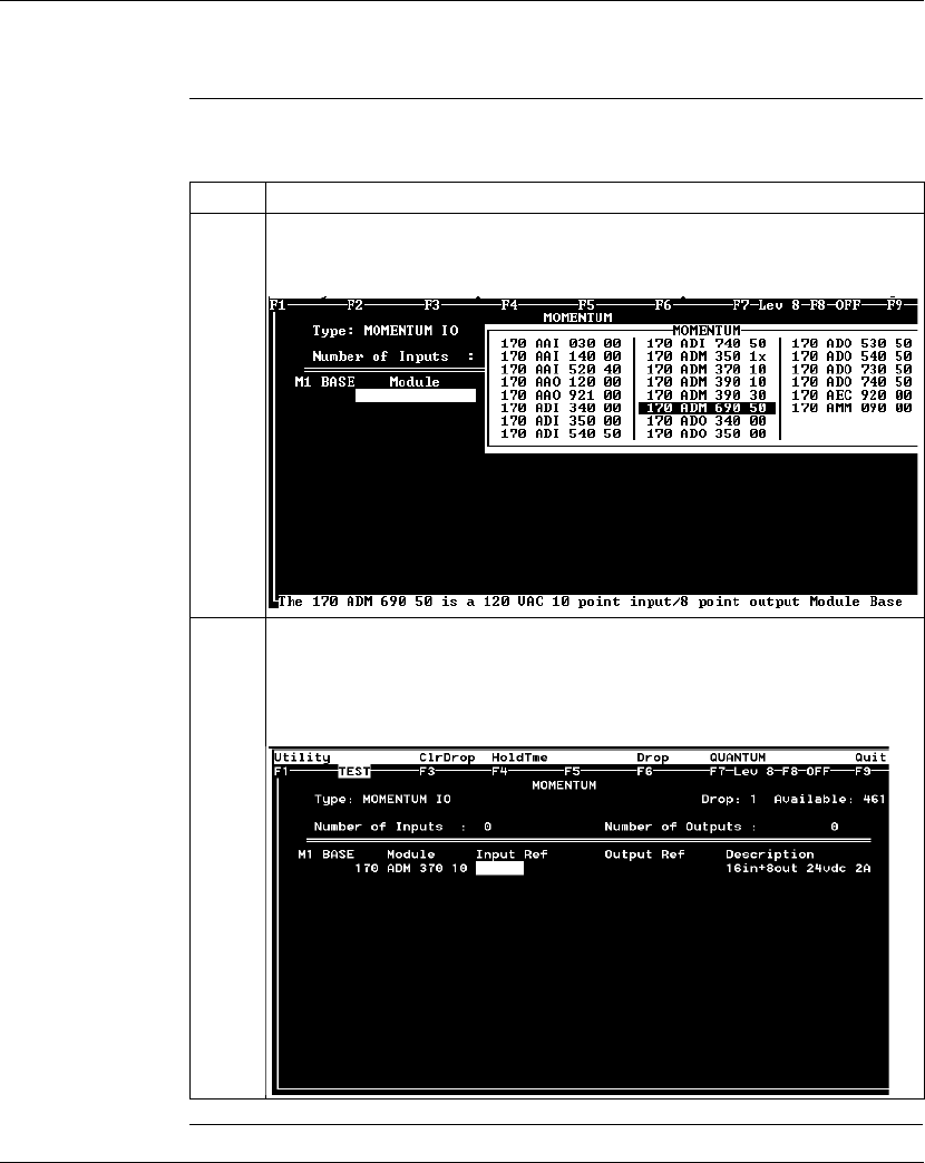
Configuring an M1 CPU with Modsoft
870 USE 101 10 V.2 243
Accessing and Editing the I/O Map, Continued
Editing the Local
I/O Map To edit the Local I/O Map, perform the steps in the following table.
Continued on next page
Step Action
1To select the local base unit for drop 1, push <Shift><?>.
Result: A list of all available Momentum base units appears in a window over the
I/O Map screen, as shown below. The list includes all Momentum I/O bases.
2Move the cursor onto the model number of your local base unit
(e.g., the 170 ADM 370 10 24 VDC 16-point in/ 8-point out base in the sample
screen). Push <Enter>.
Result: The module type and description of the base you select appears in the
(Drop 1) I/O Map screen:
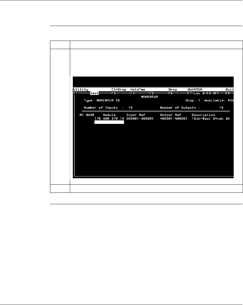
Configuring an M1 CPU with Modsoft
244 870 USE 101 10 V.2
Accessing and Editing the I/O Map, Continued
Editing the Local
I/O Map
Continued on next page
Step Action
3Assign the appropriate state RAM reference(s) to the unit.
Example: In the screen below, one 3
x
register (300001) has been assigned for the
input points and one 4
x
register (400001) has been assigned for the output points:
4Press <Esc> to return to the Configuration Overview editor.
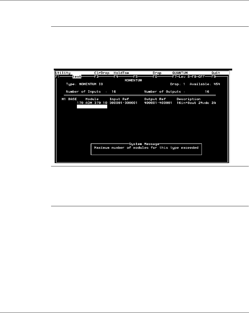
Configuring an M1 CPU with Modsoft
870 USE 101 10 V.2 245
Accessing and Editing the I/O Map, Continued
Local I/O Only This screen is always used to I/O Map the local I/O base only. No other I/O base
units can be I/O Mapped on this screen.
If you attempt to select a second Momentum I/O base in this screen, the following
error message appears:
I/O Bus: A
Special Case If you are I/O Mapping a Processor Adapter which supports I/OBus communication
stations, you will need to go to a separate I/O Map screen for Drop 2. That process
is described in
I/O Mapping an I/OBus Network with Modsoft
on page 247.
7

Configuring an M1 CPU with Modsoft
246 870 USE 101 10 V.2

870 USE 101 10 V.2 247
I/O Mapping an I/OBus Network
with Modsoft
At a Glance
Purpose This chapter describes how to I/O Map an I/OBus network using Modsoft 2.6.
Topics This chapter contains the following topics:
Note: Modsoft 2.6 does not support the 171 CCC 960 20 Processor Adapter.
This Processor Adapter must be configured with Concept.
For This Topic... See Page...
Supporting an I/O Map for an I/OBus Network 248
Accessing an I/O Map Screen for an I/OBus Network 250
Editing the I/OBus I/O Map 252

I/O Mapping an I/OBus Network with Modsoft
248 870 USE 101 10 V.2
Supporting an I/O Map for an I/OBus Network
Introduction The 171 CCS 760 00 and 171 CCC 760 10 Processor Adapters have an I/OBus
communication port that enables them to control and communicate with network
slave I/O.
If you are using I/OBus to control network I/O, you need to write an I/O Map in your
configuration. This section describes the configuration parameters required to
support an I/O Map for I/OBus.
I/O Map
Reserved Words By default, 512 words are reserved for I/O Mapping. This may or may not be the
appropriate memory allocation to support your I/OBus network. A rule of thumb for
roughly estimating the number of words required for I/O Mapping is:
l16 words for overhead
l10 words/module on the network (including both the local and the network I/O)
The idea behind adjusting the memory size is to allow you to completely I/O Map
your network while preserving as much user memory as possible for your
application program.
Required
Settings Be sure that the following parameters are set on the Configuration Overview
screen:
Continued on next page
Parameter Setting
Processor type 12.0 for a 171 CCS 760 00
Processor Adapter
18.0 for a 171 CCC 760 10
Processor Adapter
Number of segments 2
I/O Map reserved words Enough to support your I/O map

I/O Mapping an I/OBus Network with Modsoft
870 USE 101 10 V.2 249
Supporting an I/O Map for an I/OBus Network, Continued
Next Step Once you are sure that your Configuration Overview parameters are set properly,
you can access a second I/O Map screen for the I/OBus network.
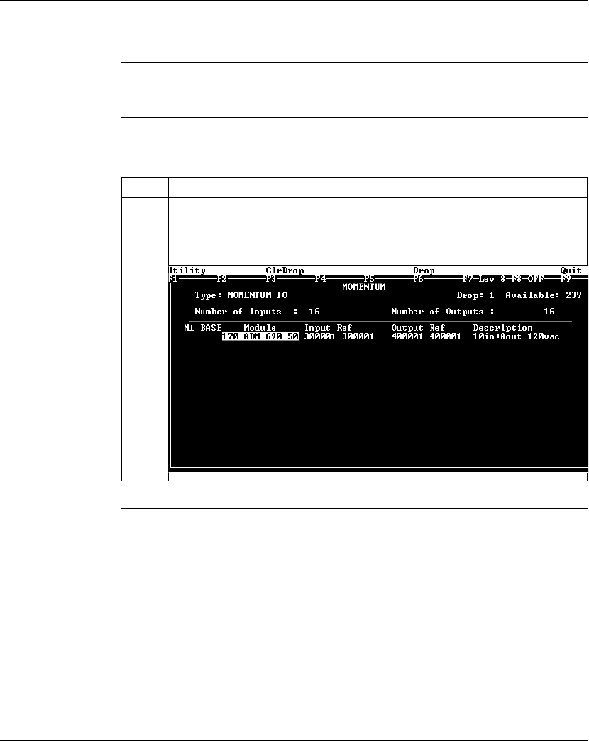
I/O Mapping an I/OBus Network with Modsoft
250 870 USE 101 10 V.2
Accessing an I/O Map Screen for an I/OBus Network
Overview This section describes how to access an I/O Map screen for an I/OBus network.
Procedure To access the I/O Map screen for your I/OBus network, perform the steps in the
following table.
Continued on next page
Step Action
1From the Configuration Overview screen, move the cursor onto the I/OMap
command on the top menu and push <Enter>.
Result: The Type: MOMENTUM I/O screen for the local I/O base appears.
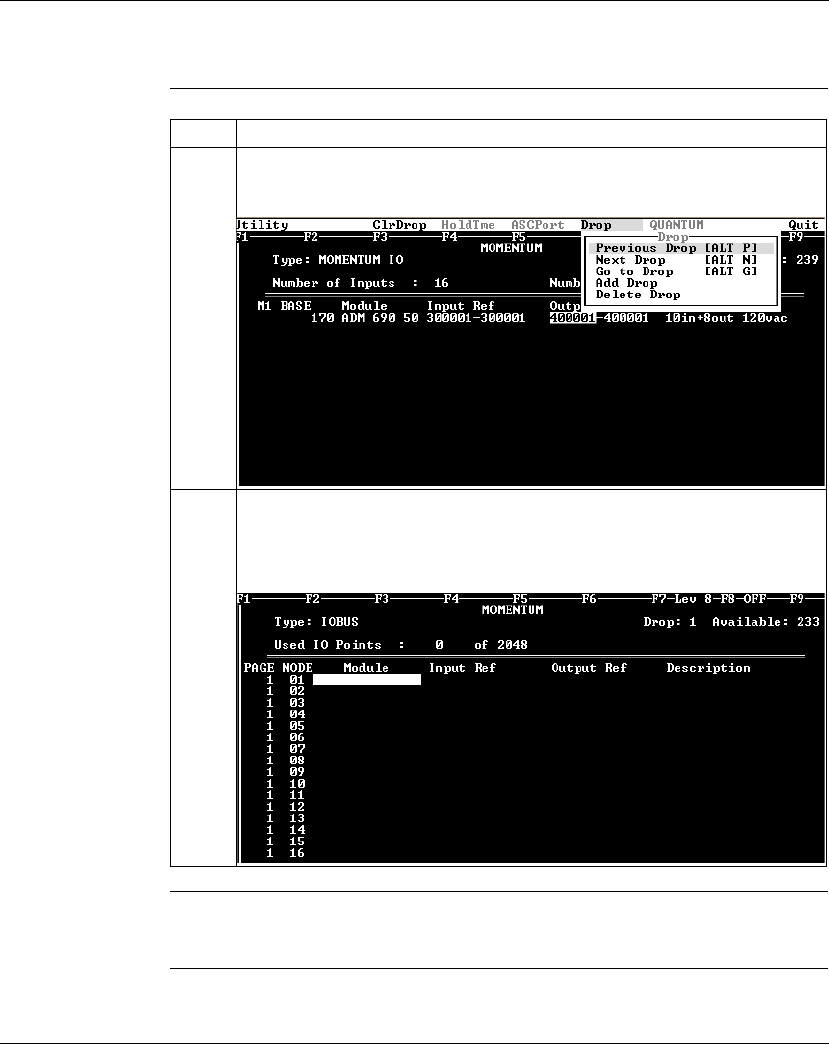
I/O Mapping an I/OBus Network with Modsoft
870 USE 101 10 V.2 251
Accessing an I/O Map Screen for an I/OBus Network, Continued
Procedure,
Continued
Next Step Editing the I/OBus I/O Map.
Step Action
2Select Drop from the top menu bar of this I/O Map screen.
Result: A pull-down menu appears.
3Select Add Drop (or Next Drop if you have already established the drop) from the
pull-down menu, then push <Enter>.
Result: A new I/O Map screen appears labeled Type: IOBUS. You are now ready
to start I/O Mapping the I/OBus network.
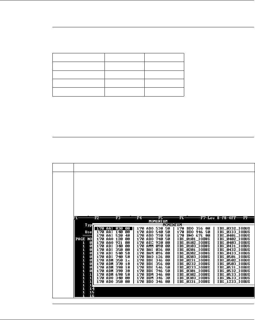
I/O Mapping an I/OBus Network with Modsoft
252 870 USE 101 10 V.2
Editing the I/OBus I/O Map
Overview The maximum number of modules which can be I/O Mapped on the I/OBus
network depends on your Processor Adapter:
You may use up to 16 IOBUS screens to map your I/OBus network. Each page
allows you to enter up to 16 I/O base and/or InterBus I/O modules.
The first column on the screen tells you which page you are on.
Procedure To enter I/O bases or Interbus I/O modules in the I/OBus I/O Map, perform the
steps in the following table.
Continued on next page
Processor Adapter Max. Modules Max. I/O Bits
171 CCS 760 00 128 2048
171 CCC 760 10 256 4096
171 CCC 960 20 128 2049
171 CCC 960 30 256 4096
Step Action
1Place the cursor in the Module column in row 1 (for NODE 01) and push the <F8>
key OR <Shift> <?>.
Result: A list of I/O names appears, as shown below. This list includes model
numbers for the available Momentum I/O bases and Terminal Block I/O modules.
It also includes a series of InterBus Module Identifier codes (see list at the end of
this section).
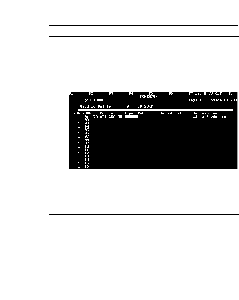
I/O Mapping an I/OBus Network with Modsoft
870 USE 101 10 V.2 253
Editing the I/OBus I/O Map, Continued
Procedure,
Continued
Continued on next page
Step Action
2Move the cursor onto the desired model number and push <Enter>.
Result: The module type and its description are displayed on the I/O Map screen.
The cursor is positioned so that you can assign the appropriate state RAM
reference(s) to the unit.
Example: If you select a 170 ADI 350 00 32-point input base, the screen will look
like this:
3Enter the desired reference number–in this case a 3
x
register (300020), which will
be the first of two contiguous input registers for the 32-bit input base. The second
register is automatically assigned.
4Move the cursor to the Module column opposite NODE 02 and push <Shift> <?>.
Result: The base/module selection popup appears again over the I/O Map
screen.
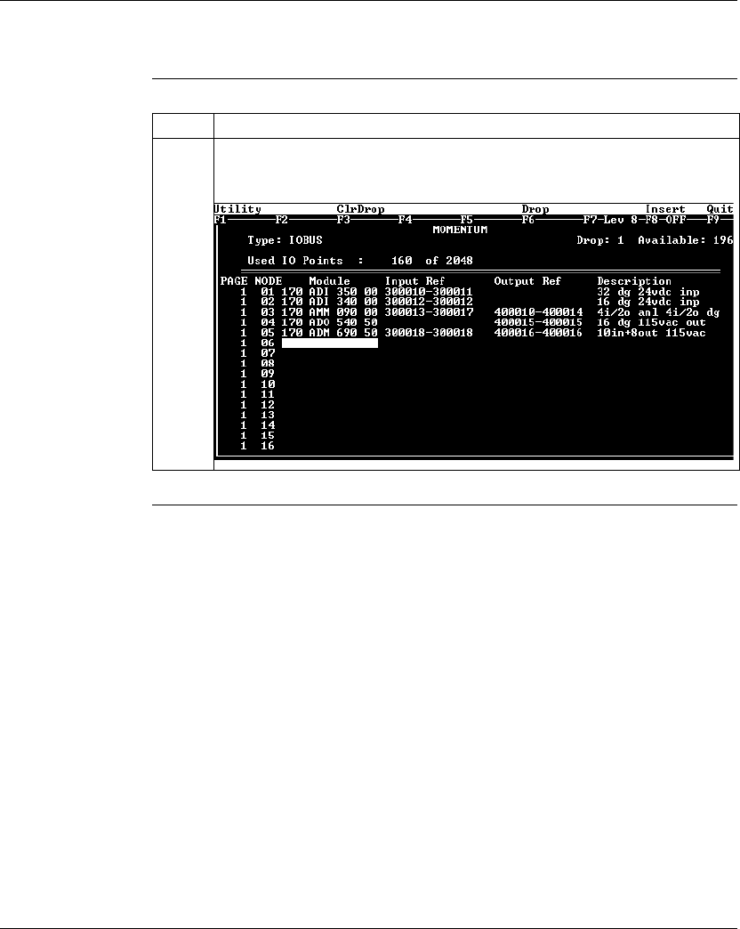
I/O Mapping an I/OBus Network with Modsoft
254 870 USE 101 10 V.2
Editing the I/OBus I/O Map, Continued
Procedure,
Continued
Continued on next page
Step Action
5Continue to select and map modules one after the other. You must enter the
modules in contiguous node slots on the screen, e.g. you cannot enter a module in
slot 7 if you have not filled slot 6.

I/O Mapping an I/OBus Network with Modsoft
870 USE 101 10 V.2 255
Editing the I/OBus I/O Map, Continued
Generic InterBus
Module Identifier
Codes
InterBus device manufacturers embed an identifier code in their network slave
modules in conformance with InterBus standards. The code identifies a device by
its I/O type but not its specific model or name.
I/OBus recognizes the InterBus identifier codes provided below and allows you to
I/O Map devices that use these codes. However, you cannot use the module zoom
screens to define the parameters for these InterBus modules.
Continued on next page
Identifier Code I/O Type
0101_IOBUS One-word discrete output
0102_IOBUS One-word discrete input
0103_IOBUS One-word discrete bidirectional
0201_IOBUS Two-word discrete output
0202_IOBUS Two-word discrete input
0203_IOBUS Two-word discrete bidirectional
0231_IOBUS Two-word analog output
0232_IOBUS Two-word analog input
0233_IOBUS Two-word analog bidirectional
0301_IOBUS Three-word discrete output
0302_IOBUS Three-word discrete input
0303_IOBUS Three-word discrete bidirectional
0331_IOBUS Three-word analog output
0332_IOBUS Three-word analog input
0333_IOBUS Three-word analog bidirectional
0401_IOBUS Four-word discrete output
0402_IOBUS Four-word discrete input
0403_IOBUS Four-word discrete bidirectional
0431_IOBUS Four-word analog output
0432_IOBUS Four-word analog input
0433_IOBUS Four-word analog bidirectional

I/O Mapping an I/OBus Network with Modsoft
256 870 USE 101 10 V.2
Editing the I/OBus I/O Map, Continued
Generic InterBus
Module Identifier
Codes, Continued
Moving Between
Pages To move from one I/O Map page to the another, use the <PageUp> and
<PageDown> keys.
l<PageDown> opens the next page–e.g., to move from page 1 to page 2
l<PageUp> opens the previous page–e.g., to move from page 2 to page 1
Identifier Code I/O Type
0501_IOBUS Five-word discrete output
0502_IOBUS Five-word discrete input
0503_IOBUS Five-word discrete bidirectional
0531_IOBUS Five-word analog output
0532_IOBUS Five-word analog input
0533_IOBUS Five-word analog bidirectional
0633_IOBUS Eight-word analog bidirectional
1233_IOBUS Sixteen-word analog bidirectional

870 USE 101 10 V.2 257
Configuring a Modbus Plus
Network in Modsoft with Peer Cop
At a Glance
Purpose Communication transactions over Modbus Plus are defined in Modsoft 2.6 by a
configuration tool called Peer Cop. This section uses examples to explain how to
use Peer Cop to configure the two types of network architecture:
lAn I/O network, where the Peer Cop of the CPU defines all the communication
transactions over the full network.
lA supervisory network with two or more CPUs communicating with each other
and with additional devices on the network.
In This Chapter This chapter contains the following sections:
For This Topic... See Section... On Page...
Getting Started 1 258
Using Modbus Plus to Handle I/O 2 263
Passing Supervisory Data over Modbus Plus 3 281

Using Peer Cop with Modsoft
258 870 USE 101 10 V.2
Section 10.1
Getting Started
Overview
Purpose This section explains how to access the Peer Cop Configuration Extension screen
and describes the default screen.
In This Section This section contains the following topics:
For This Topic... See Page...
Accessing the Peer Cop Configuration Extension Screen 259
The Default Peer Cop Screen 261

Using Peer Cop with Modsoft
870 USE 101 10 V.2 259
Accessing the Peer Cop Configuration Extension Screen
Introduction Before you can access the Peer Cop Configuration Extension screen, you must
have specified enough extension memory to support your Peer Cop database.
This section describes how to access the screen and, if necessary, adjust the
amount of configuration extension memory.
Accessing the
Screen Starting from the Configuration Overview screen, select Peer Cop from the Cfg Ext
menu.
Adjusting
Extension
Memory
Extension memory is specified as a number of 16-bit words. That number is
entered in the ExtSize field of the Configuration Overview screen. Once an
adequate number of words has been specified there, Peer Cop will be enabled in
the Cfg Ext menu.
Extension
Memory Size The minimum Peer Cop memory requirement is 20 words. The maximum is 1366
words.
Continued on next page
Note: If Peer Cop is disabled in the pull-down list, you will need to specify
enough extension memory to support your Peer Cop database before you
can continue.

Using Peer Cop with Modsoft
260 870 USE 101 10 V.2
Accessing the Peer Cop Configuration Extension Screen, Continued
Estimating How
Much Memory to
Reserve
Follow these guidelines for estimating the amount of extension memory you will
need for your Peer Cop database:
For... Add... Up to a maximum of...
Overhead 9 words --
Global output 5 words --
Global input number of words=
number of devices x
(1 + 2 x number of device subentries)
1088 words
Specific output 2 words for every device entry in Peer Cop 128 words
Specific input 2 words for every device entry in Peer Cop 128 words
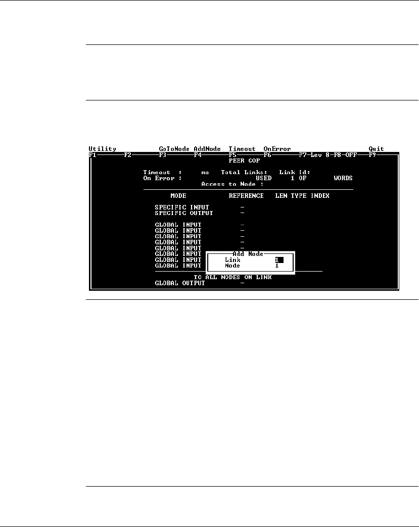
Using Peer Cop with Modsoft
870 USE 101 10 V.2 261
The Default Peer Cop Screen
Overview This section describes the Peer Cop screen as it appears the first time you access
it.
Illustration The first time you click on Peer Cop in the Cfg Ext menu, the following screen
appears:
Description The Peer Cop screen is divided into two regions by a horizontal rule.
At the top of the screen is a group of Peer Cop summary entries
lTimeout
lON Error
lTotal Links
lAccess to Node
The lower half of the screen displays the Peer Cop reference information, i.e., the
register or discrete references that the CPU uses to handle specific and global
inputs/outputs with other nodes on the network.
The Add Node popup menu appears near the bottom of the screen.
Continued on next page

Using Peer Cop with Modsoft
262 870 USE 101 10 V.2
The Default Peer Cop Screen, Continued
Next Step No values are set anywhere in the default Peer Cop screen. The following two
examples show how to set up Peer Cop to configure different types of Modbus Plus
networks.

Using Peer Cop with Modsoft
870 USE 101 10 V.2 263
Section 10.2
Using Modbus Plus to Handle I/O
Overview
Purpose This section uses an example to explain how to configure a Modbus Plus network
for I/O servicing. In this example, a CPU will control four Momentum I/O modules.
In This Section This section contains the following topics:
For This Topic... See Page...
Devices on the Network 264
Defining the Link and Accessing a Node 265
Confirming the Peer Cop Summary Information 268
Specifying References for Input Data 272
Accessing the Remaining Devices 276
Completing the I/O Device Configuration in Peer Cop 278

Using Peer Cop with Modsoft
264 870 USE 101 10 V.2
Devices on the Network
Introduction This section describes the five devices which comprise the sample network and the
strategy used to assign addresses.
The Network
Devices The following table lists the Modbus Plus address and components of each
Momentum module on the network:
Address
Strategy In this type of architecture, assign the lowest network address (1) to the CPU.
When the network initializes, the CPU will be the first device to get the token, and
the token rotation table will be built with respect to the controlling device on the
network.
Modbus Plus
Address I/O Base Type Adapter Type
1(type not specified) M1 Processor Adapter
(type not specified)
172 PNN 210 22
Modbus Plus Option Adapter
2170 ADI 340 00
16-point input
170 PNT 110 20
Modbus Plus Communication Adapter
3170 ADO 340 00
16-point output
170 PNT 110 20
Modbus Plus Communication Adapter
4170 ADI 350 00
32-point input
170 PNT 110 20
Modbus Plus Communication Adapter
5170 ADO 350 00
32-point output
170 PNT 110 20
Modbus Plus Communication Adapter

Using Peer Cop with Modsoft
870 USE 101 10 V.2 265
Defining the Link and Accessing a Node
Overview When you reach the default Peer Cop screen, a popup menu asks you to define a
link and access a node.
What Is a Link? The
link
is the Modbus Plus network on which the CPU resides.
The only valid link value for a Momentum M1 CPU is 1. An M1 can function only on
one Modbus Plus network–multiple Modbus Plus links are not supported.
What Is a Node? The
node
is the Modbus Plus address of one of the I/O devices on the network.
A valid node value in our example is any number in the range 2...5. For our
example, we will first access the170 ADI 340 00 16-point input module at Modbus
Plus address 2.
Continued on next page
Note: Address 1, the network address of the CPU itself, is not a valid node to
access since the CPU does not need to access itself over the network.
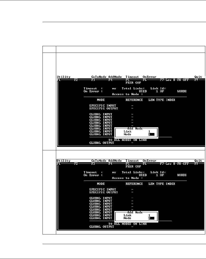
Using Peer Cop with Modsoft
266 870 USE 101 10 V.2
Defining the Link and Accessing a Node, Continued
Procedure Follow the steps in the table below to define the link and access a node, using the
popup menu.
Continued on next page
Step Action
1With the cursor flashing in the Link value field, make sure that the Link value in the
popup is 1. Push <Enter>.
Result: The Link value is set to 1, and the cursor moves to the Node field.
2Enter the value 2 in the Node field.

Using Peer Cop with Modsoft
870 USE 101 10 V.2 267
Defining the Link and Accessing a Node, Continued
Procedure,
Continued
Next Step Confirming the Peer Cop summary information.
Step Action
3Push <Enter>.
Result: The Add Node popup disappears, and the Peer Cop summary information
values are set as follows:

Using Peer Cop with Modsoft
268 870 USE 101 10 V.2
Confirming the Peer Cop Summary Information
Overview Once you have defined the link and accessed a node, the Peer Cop summary
information values assume default settings. This section describes those settings
and how to confirm or change them.
Timeout The default Timeout is 500 ms.
Timeout
is the maximum interval that Modbus Plus on a Peer-Copped device will
remain healthy without communication activity. If this interval is exceeded, the
device will clear its network health bit and will no longer try to communicate via
Modbus Plus.
The timeout interval must be in the range 20 ... 2000ms, and it must be specified as
an increment of 20ms.
For our example, we will change the timeout value to 240ms.
On Error The default On Error setting is CLEAR.
The
On Error
setting specifies how the Peer-Copped device will treat the last
values received before a timeout, once Modbus Plus communications have been
restored.
One of two settings may be used–CLEAR or HOLD. CLEAR sets all the previously
received values to 0, and HOLD retains the previous values.
For our example, we will change the setting to HOLD.
Continued on next page

Using Peer Cop with Modsoft
870 USE 101 10 V.2 269
Confirming the Peer Cop Summary Information, Continued
Procedure Follow the steps in the table below to change the Peer Cop summary information.
Continued on next page
Step Action
1Push <Tab> to move the cursor to the menu bar at the top of the Peer Cop screen.
2Move the cursor onto the Timeout command. Push <Enter>.
Result: The cursor moves into the Timeout field in the Peer Cop summary
information region, and the default value, 500, is cleared.
3Type the number 240, then push <Enter>.
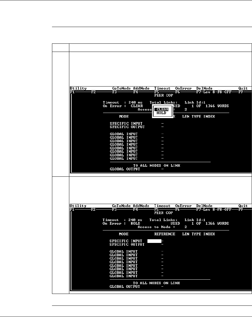
Using Peer Cop with Modsoft
270 870 USE 101 10 V.2
Confirming the Peer Cop Summary Information, Continued
Procedure,
Continued
Continued on next page
Step Action
4Now select On Error from the menu bar.
Result: The cursor moves into the On Error field in the Peer Cop summary
information region, and a popup menu appears with two choices listed – CLEAR
and HOLD.
5Move the cursor onto HOLD and push <Enter>.
Result: The On Error value in the Peer Cop summary information region is set to
HOLD. Your Peer Cop screen should now look like this:

Using Peer Cop with Modsoft
870 USE 101 10 V.2 271
Confirming the Peer Cop Summary Information, Continued
Next Step Specifying references for input data.

Using Peer Cop with Modsoft
272 870 USE 101 10 V.2
Specifying References for Input Data
Introduction The Peer Cop screen is now set to access the device at Modbus Plus address 2,
which for this example is a 170 ADI 340 00 16-point input module.
This section explains how to specify the reference for input data from this module.
Device
Requirements When you use Peer Cop to handle a Modbus Plus I/O architecture, you need to be
aware of the type of I/O you are configuring at each network address. Peer Cop
does not know that the device at address 2 is a discrete 16-point input module.
You need to know that a specific input reference with a length of one word (16 bits)
is required to handle this module.
We will assign a 3
x
register (300016) as a specific input to the CPU. When the 170
ADI 340 00 sends input data to the CPU, it will be sent to this register.
Continued on next page
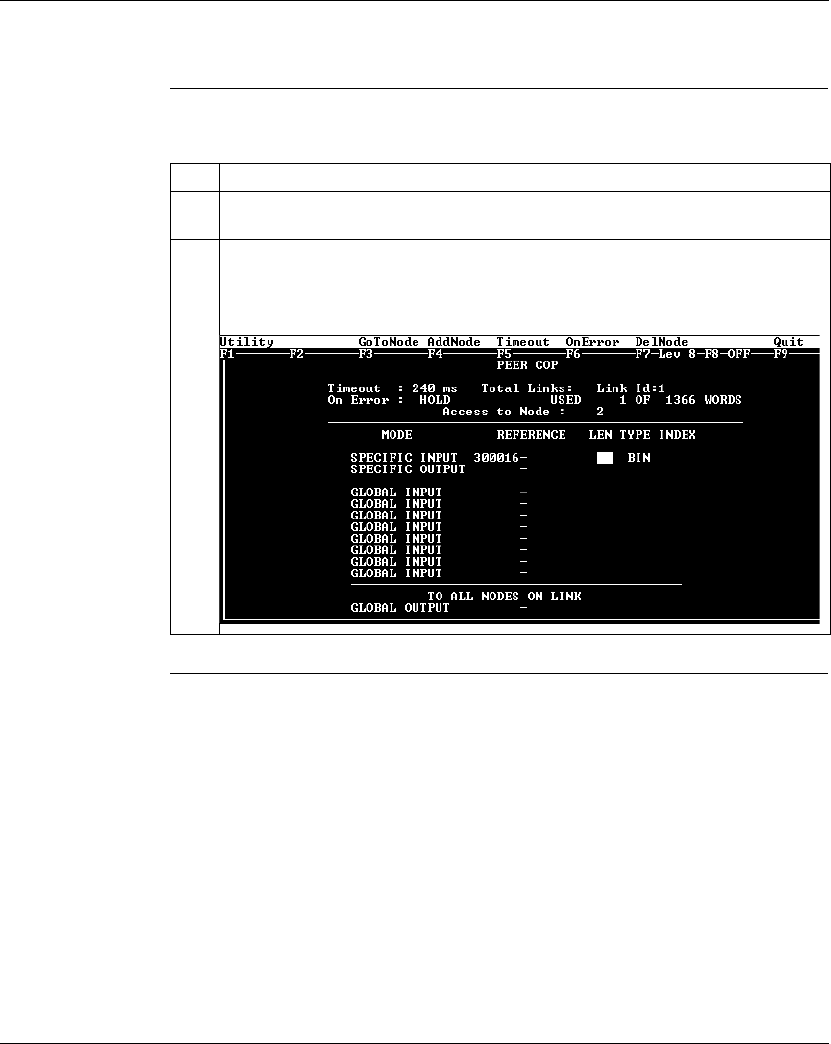
Using Peer Cop with Modsoft
870 USE 101 10 V.2 273
Specifying References for Input Data, Continued
Procedure Follow the steps in the table below to define the specific input in Peer Cop.
Continued on next page
Step Action
1Move the cursor to the REFERENCE column of the SPECIFIC INPUT field, using the
cursor arrow keys.
2Type the value 300016 in the REFERENCE column of the SPECIFIC INPUT field,
then push <Enter>.
Result: The cursor moves into the LEN column of the SPECIFIC INPUT field.
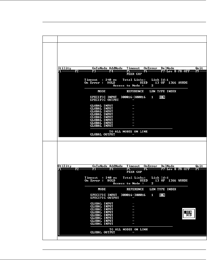
Using Peer Cop with Modsoft
274 870 USE 101 10 V.2
Specifying References for Input Data, Continued
Procedure,
Continued
Continued on next page
Step Action
3Type the value 1 in the LEN column of the SPECIFIC INPUT field, indicating that the
device at address 2 will transmit 1 word of data (or 16 bits). Then push <Enter>.
Result: The cursor is now on BIN (binary) the TYPE column.
4Push <Enter>.
Result: A popup menu appears. You can choose between leaving the data type as
binary or changing it to BCD.
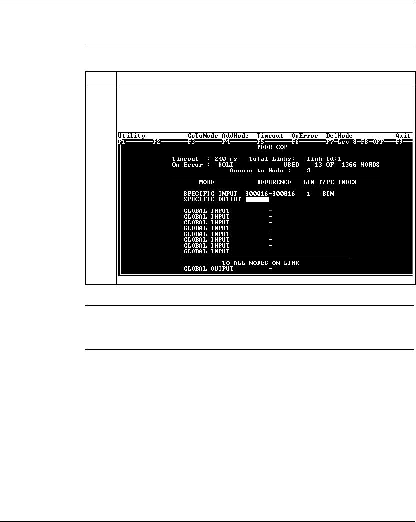
Using Peer Cop with Modsoft
870 USE 101 10 V.2 275
Specifying References for Input Data, Continued
Procedure,
Continued
Next Step Accessing the remaining devices.
Step Action
5In this case, we will leave the default BIN setting. Push <Enter>.
Result: The Peer Cop screen is now set to handle a 16-point input module at
Modbus Plus address 2. The screen should like this:
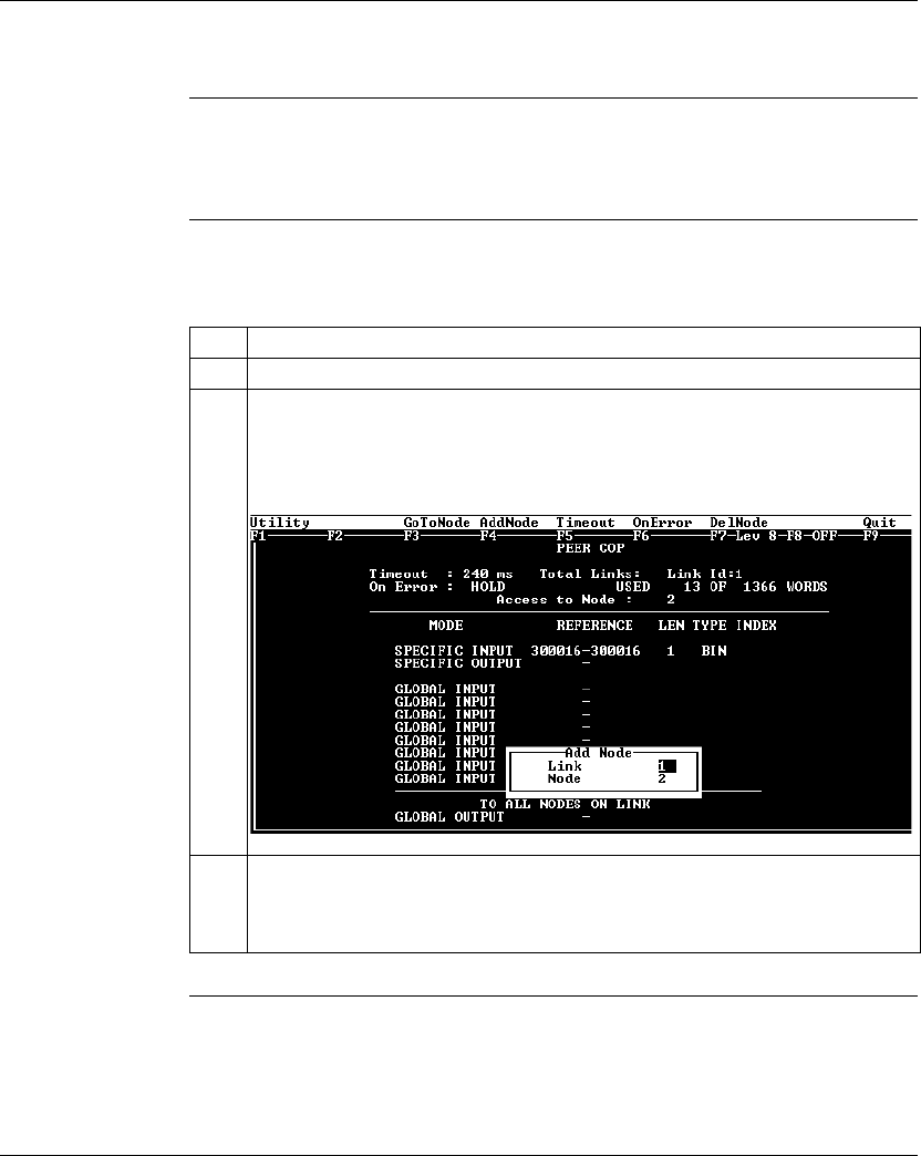
Using Peer Cop with Modsoft
276 870 USE 101 10 V.2
Accessing the Remaining Devices
Introduction The I/O modules at Modbus Plus addresses 3 ... 5 can be configured individually in
a manner similar to that used for the 170 ADI 340 00 module at address 2.
Procedure Follow the steps in the table below to access a new device address (in this case,
address 3), using the AddNode command.
Continued on next page
Step Action
1Push <Tab> to move the cursor to the menu at the top of the Peer Cop screen.
2Using a left or right arrow key as necessary, move the cursor onto the AddNode
command. Push <Enter>.
Result: The Add Node popup appears over the Peer Cop screen with the cursor
flashing in the Link value field.
3Make sure that the Link value in the Add Node popup is 1. Push <Enter>.
Result: The Link value is set to 1, and the cursor moves to the Node value field of
the Add Node popup.
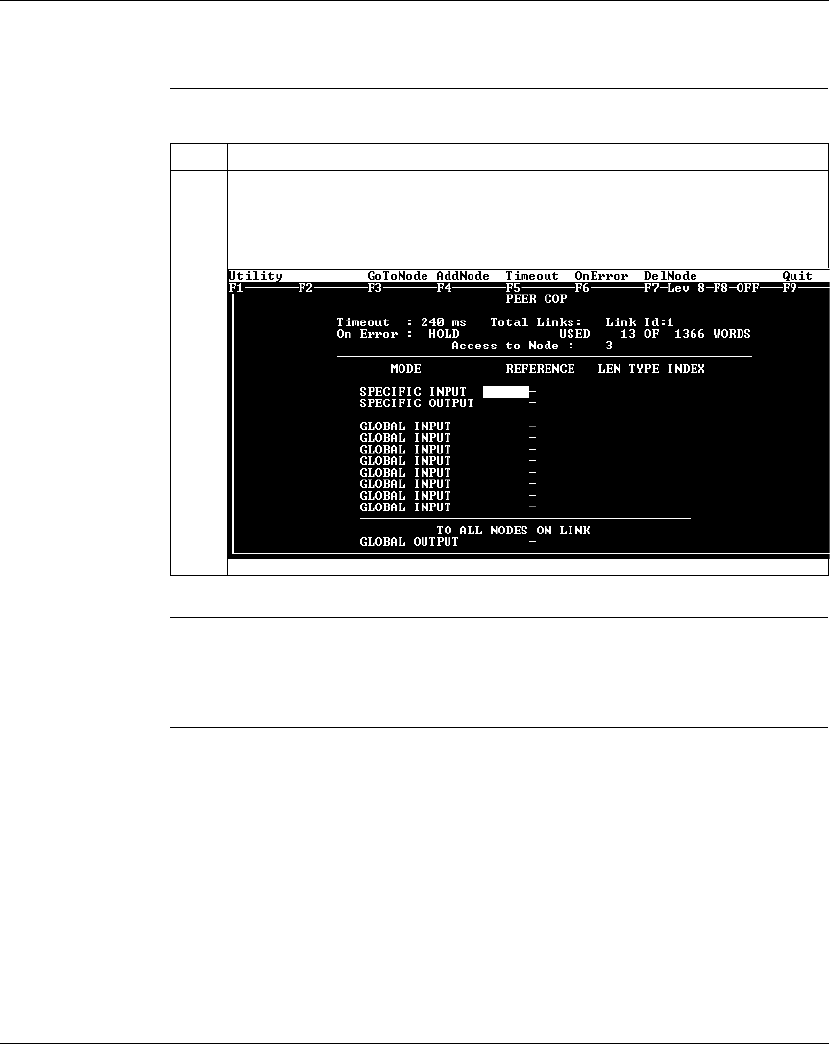
Using Peer Cop with Modsoft
870 USE 101 10 V.2 277
Accessing the Remaining Devices, Continued
Procedure,
Continued
Next Step You are now ready to configure Peer Cop for the device at Modbus Plus address 3,
which for this example is a 170 ADO 340 00 16-point output module.
Step Action
4Enter the value 3 in the Node field. Push <Enter>.
Result: The Add Node popup disappears, and the Peer Cop summary information
values are set as follows:
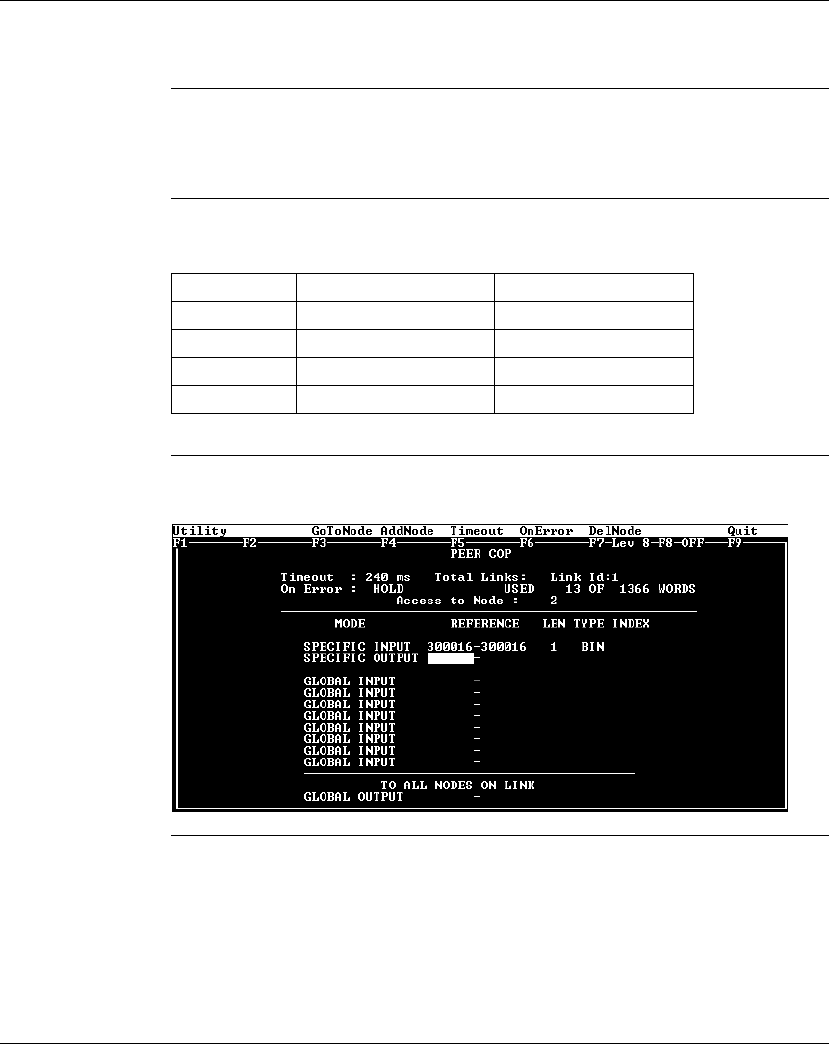
Using Peer Cop with Modsoft
278 870 USE 101 10 V.2
Completing the I/O Device Configuration in Peer Cop
Introduction Using the procedures described previously, you can complete the I/O configuration
in Peer Cop. This section shows completed Peer Cop screens for this example.
Register
Assignments For this example, we have made the following register assignments:
Completed
Screen: Node 2 The completed Peer Cop screen for node 2 should look like this:
Continued on next page
MB+ Address Device Type Register Assignment
2 16-point discrete input 300016
3 16-point discrete output 400016
4 32-point discrete input 300017 and 300018
5 32-point discrete output 400017 and 400018
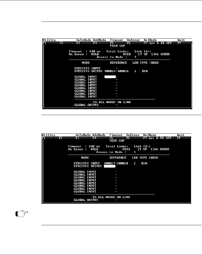
Using Peer Cop with Modsoft
870 USE 101 10 V.2 279
Completing the I/O Device Configuration in Peer Cop, Continued
Completed
Screen: Node 3 The completed Peer Cop screen for node 3 should look like this:
Completed
Screen: Node 4 The completed Peer Cop screen for node 4 should look like this:
Continued on next page
Note: The lengths (LEN) for the 32-bit I/O devices at addresses 4 and 5 need to
be specified as 2 words (32 bits).
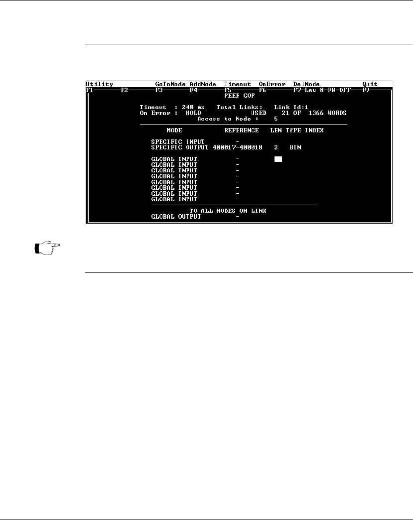
Using Peer Cop with Modsoft
280 870 USE 101 10 V.2
Completing the I/O Device Configuration in Peer Cop, Continued
Completed
Screen: Node 5 The completed Peer Cop screen for node 5 should look like this:
Note: The lengths (LEN) for the 32-bit I/O devices at addresses 4 and 5 need to
be specified as 2 words (32 bits).

Using Peer Cop with Modsoft
870 USE 101 10 V.2 281
Section 10.3
Passing Supervisory Data over Modbus Plus
Overview
Purpose This Peer Cop example deals with a network where three CPUs communicate over
Modbus Plus. Each device needs its own Peer Cop configuration.
In This Section This section contains the following topics:
For This Topic... See Page...
Devices on the Network 282
Configuring a Node to Exchange Data 283
Confirming the Peer Cop Summary Information 286
Specifying References for Input and Output Data 287
Defining the References for the Next Node 292
Defining References for the Supervisory Computer 297
Completing the Configuration 302

Using Peer Cop with Modsoft
282 870 USE 101 10 V.2
Devices on the Network
Introduction This section describes the three CPUs which exchange data over the sample
Modbus Plus network and the strategy used to assign node addresses.
Devices The three CPUs and their functions are described in the following table:
Address
Strategy In this type of architecture, assign the lowest network address (1) to the
supervisory computer. When the network initializes, the supervisor will be the first
device to get the token, and the token rotation table will be built with respect to the
supervising device.
MB+ Address CPU Function
1 Pentium supervisory computer with
an AT984 host-based PLC card
Receives specific input data
and sends global outputs
2 171 CCS 760 00 Momentum M1
Processor Adapter with
172 PNN 210 22 Modbus Plus
Option Adapter
Controls I/OBus network
and exchanges data with
AT984 supervisor
3 171 CCS 760 00 Momentum M1
Processor Adapter with
172 PNN 210 22 Modbus Plus
Option Adapter
Controls I/OBus network
and exchanges data with
AT984 supervisor

Using Peer Cop with Modsoft
870 USE 101 10 V.2 283
Configuring a Node to Exchange Data
Getting Started To Peer Cop this sample configuration, each CPU must be separately programmed
to communicate with the others over Modbus Plus. Begin by connecting your
programming panel to the 171 CCS 760 00 Momentum M1 device at Modbus Plus
address 2. Access the Peer Cop with your Modsoft 2.6 software.
When you reach the default Peer Cop screen, you need to initialize the summary
information region. To do this, define a link value and a node value in the Add Node
popup.
What Is a Link? The
link
is the Modbus Plus network on which the CPU resides.
The only valid link value for a Momentum M1 CPU is 1. An M1 can function only on
one Modbus Plus network–multiple Modbus Plus links are not supported.
What Is a Node? The
node
is the Modbus Plus address of one of the I/O devices on the network.
For our example, we will first access the AT984 supervisory PLC at Modbus Plus
address 1.
Continued on next page
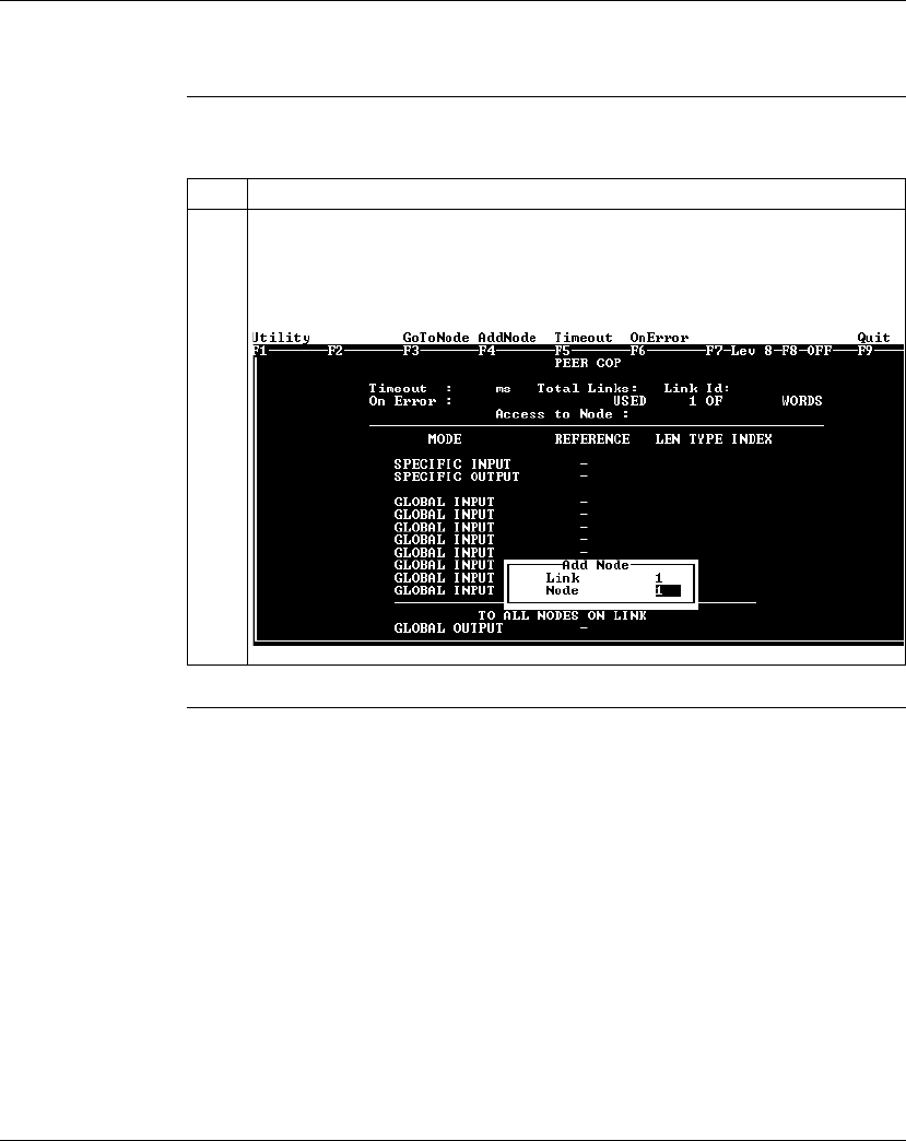
Using Peer Cop with Modsoft
284 870 USE 101 10 V.2
Configuring a Node to Exchange Data, Continued
Procedure Follow the steps in the table below to define the link and access a node.
Continued on next page
Step Action
1With the cursor flashing in the Link value field of the Add Node popup, make sure
that the Link value in the popup is 1. Push <Enter>.
Result: The Link value is set to 1, and the cursor moves to the Node value field of
the Add Node popup.
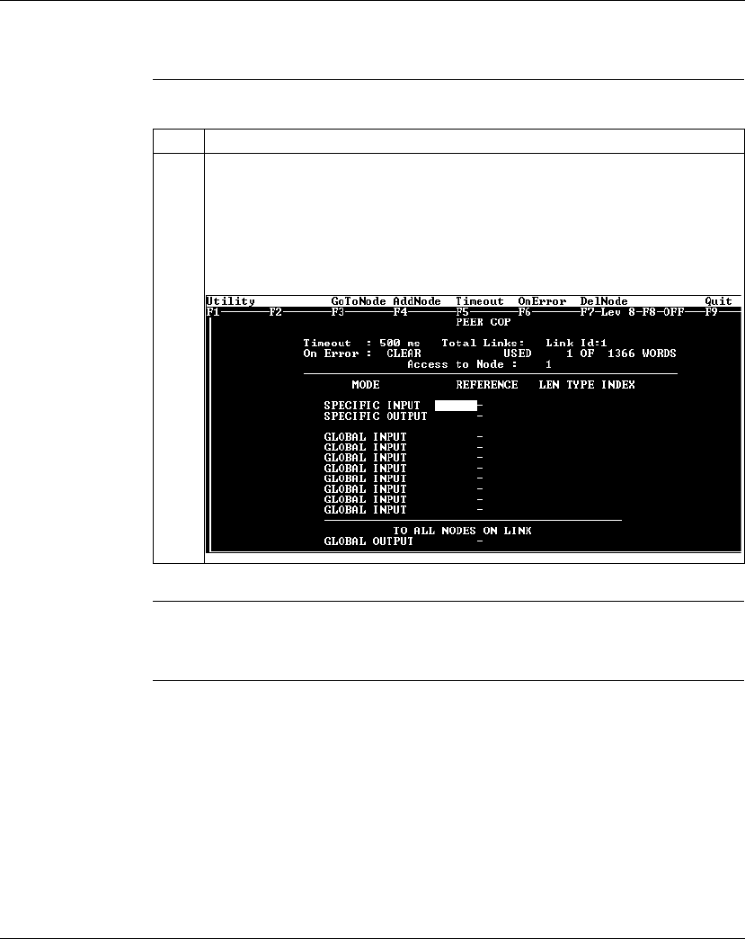
Using Peer Cop with Modsoft
870 USE 101 10 V.2 285
Configuring a Node to Exchange Data, Continued
Procedure,
Continued
Next Step Confirming the Peer Cop summary information.
Step Action
2If the value in the Node field is 1, as in our example, press <Enter>.
Otherwise, enter the value 1 in the Node field to indicate that you will access the
CPU at address 1. Then press <Enter>.
Result: The Add Node popup disappears, and the Peer Cop summary information
values are set as follows:

Using Peer Cop with Modsoft
286 870 USE 101 10 V.2
Confirming the Peer Cop Summary Information
Overview Once you have defined the link and accessed a node, the Peer Cop summary
information values assume default settings. This section describes those settings.
Timeout The default Timeout is 500 ms.
Timeout
is the maximum interval that Modbus Plus on a Peer-Copped device will
remain healthy without communication activity. If this interval is exceeded, the
device will clear its network health bit and will no longer try to communicate via
Modbus Plus.
The timeout interval must be in the range 20 ... 2000 ms, and it must be specified
as an increment of 20 ms.
For our example, we will use the default setting.
On Error The default On Error setting is CLEAR.
The
On Error
setting specifies how the Peer-Copped device will treat the last
values received before a timeout, once Modbus Plus communications have been
restored.
One of two settings may be used–CLEAR or HOLD. CLEAR sets all the previously
received values to 0, and HOLD retains the previous values.
For our example, we will use the default setting.
Next Step Specifying references for input and output data.
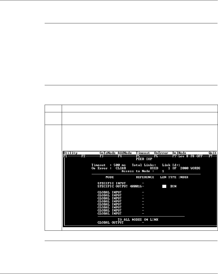
Using Peer Cop with Modsoft
870 USE 101 10 V.2 287
Specifying References for Input and Output Data
Overview We will now set up the 171 CCS 760 00 Momentum M1 CPU at Modbus Plus
address 2. This device will:
lsend eight 4
x
registers of specific output to the supervisory computer at
Modbus Plus address 1.
lreceive five 4
x
registers of global input from the supervisory computer. These
registers are the first five registers in a 10-register block broadcast by the
supervisor.
Defining the
Specific Output The following table describes how to define the specific output in Peer Cop.
Continued on next page
Step Action
1Move the cursor to the REFERENCE column of the SPECIFIC OUTPUT field with
the cursor arrow keys.
2In the REFERENCE column of the SPECIFIC OUTPUT field, type the value
400016. Push <Enter>.
Result: The cursor moves into the LEN column of the SPECIFIC OUTPUT field.

Using Peer Cop with Modsoft
288 870 USE 101 10 V.2
Specifying References for Input and Output Data, Continued
Defining the
Specific Output,
Continued
Continued on next page
Step Action
3In the LEN column of the SPECIFIC OUTPUT field, type the value 8, indicating that
the M1 CPU at address 2 will send eight 16-bit words to the supervisory PLC. Push
<Enter>.
Result: The Peer Cop screen should like this:
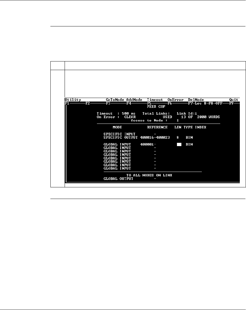
Using Peer Cop with Modsoft
870 USE 101 10 V.2 289
Specifying References for Input and Output Data, Continued
Defining the
Global Inputs Now the M1 needs to be Peer Copped to receive five words of global data from the
supervisory PLC at Modbus Plus address 1. Follow the steps in the table below to
specify the global input references.
Continued on next page
Step Action
1In the REFERENCE column on the first line of the GLOBAL INPUT field, type the
value 400001, the first register in which the CPU will store data. Push <Enter>.
Result: The cursor moves into the LEN column of the GLOBAL INPUT field.
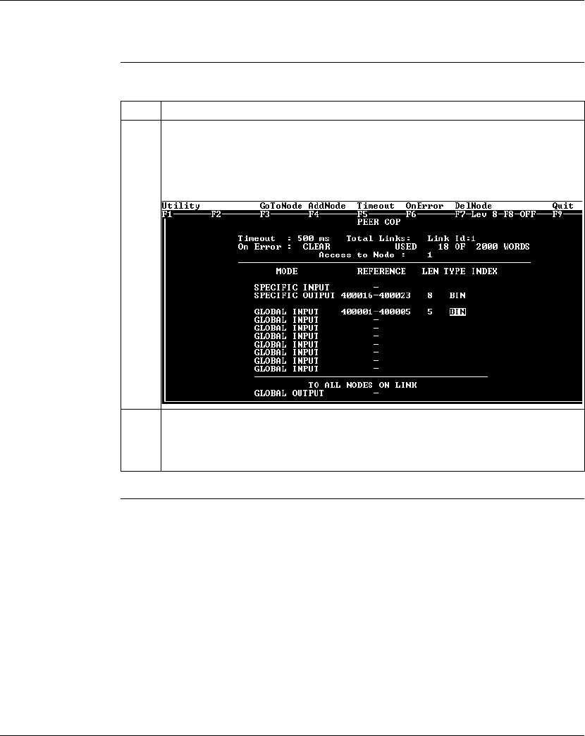
Using Peer Cop with Modsoft
290 870 USE 101 10 V.2
Specifying References for Input and Output Data, Continued
Defining the
Global Inputs,
Continued
Continued on next page
Step Action
2Type the value 5 in the LEN column of the GLOBAL INPUT field, indicating that the
CPU will receive five words of global data from the supervisory computer. Push
<Enter>.
Result: The cursor moves into the TYPE column of the GLOBAL INPUT field.
3The default data format for these words is binary (BIN). This is the desired type for
our example, so push <Enter> twice.
Result: The cursor moves into the INDEX column of the GLOBAL INPUT field.

Using Peer Cop with Modsoft
870 USE 101 10 V.2 291
Specifying References for Input and Output Data, Continued
Defining the
Global Inputs,
Continued
Next Step Defining the references for the next node.
Step Action
4 Type the value 1 in the INDEX column of the GLOBAL INPUT field, indicating that
the M1 CPU at Modbus Plus address 2 will receive the five words of global input
data beginning with word 1. Push <Enter>.
Result: The Peer Cop screen is now set to send eight words of specific output to
the supervisor at Modbus Plus address 1 and receive five words of global data from
the supervisor. The screen should like this:
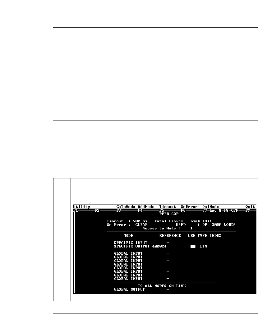
Using Peer Cop with Modsoft
292 870 USE 101 10 V.2
Defining the References for the Next Node
Overview We now want to attach the Modsoft 2.6 programming panel to the 171 CCS 760 00
Momentum M1 CPU at Modbus Plus address 3 and create a similar Peer Cop for
this device to communicate with the supervisory PLC at Modbus Plus
address 1.
In this case, we want the M1:
lto send 16 words of specific output to the supervisor.
lto receive the last seven words of global input from the supervisor. (Remember
that the supervisor will be transmitting a total of 10 contiguous words of global
data over the network.)
Link and Node
Settings Make sure that the Link setting is 1 and the Node setting is 1, indicating that this
CPU will be exchanging data with the supervisory computer at address 1.
Defining Specific
Outputs Follow the steps in the table below to define the specific output in Peer Cop.
Continued on next page
Step Action
1In the REFERENCE column of the SPECIFIC OUTPUT field, type the value
400024. Push <Enter>.
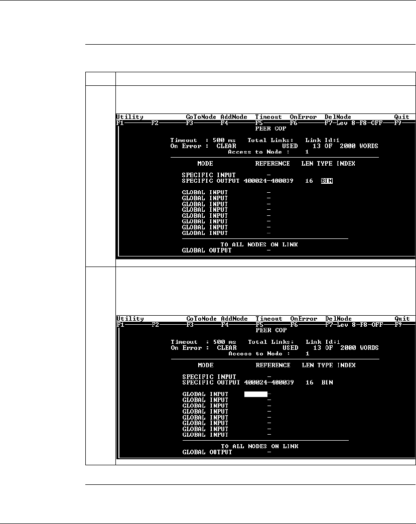
Using Peer Cop with Modsoft
870 USE 101 10 V.2 293
Defining the References for the Next Node, Continued
Defining Specific
Outputs,
Continued
Continued on next page
Step Action
2Type the value 16 in the LEN column of the SPECIFIC OUTPUT field. Push
<Enter>.
3With the TYPE column of the SPECIFIC OUTPUT filed set to BIN, push <Enter>
twice.
Result: The Peer Cop screen should like this:
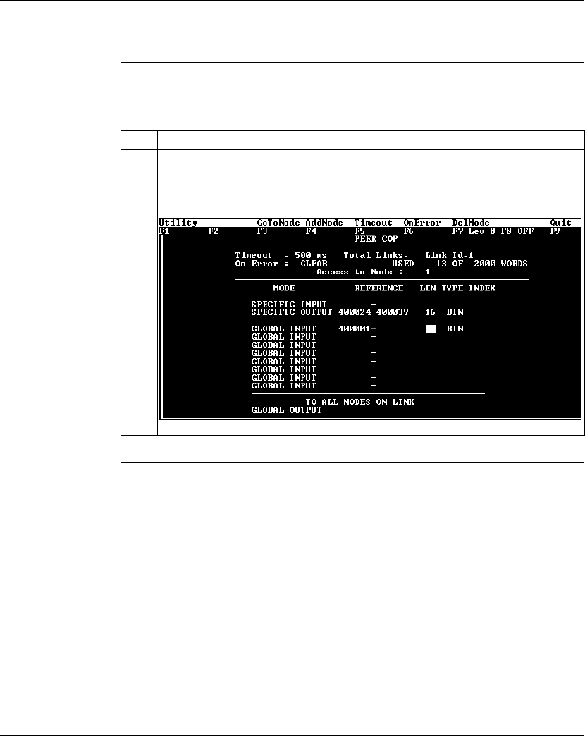
Using Peer Cop with Modsoft
294 870 USE 101 10 V.2
Defining the References for the Next Node, Continued
Defining Global
Inputs Follow the steps in the table below to define the global input data from the
supervisory PLC at Modbus Plus address 1.
Continued on next page
Step Action
1In the REFERENCE column of the first GLOBAL INPUT field, type the value 400001,
the first register which will be used to store global input data. Push <Enter>.
Result: The cursor moves to the LEN column.
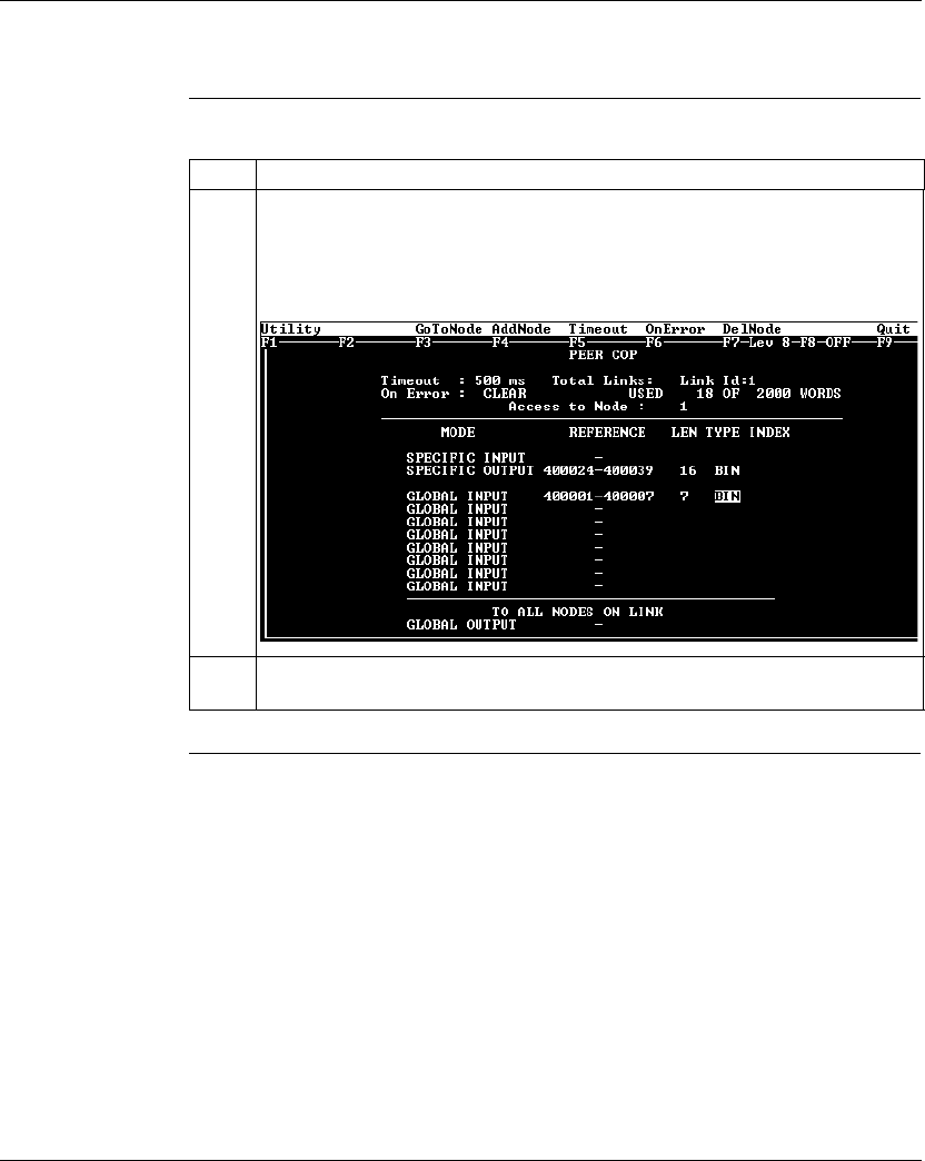
Using Peer Cop with Modsoft
870 USE 101 10 V.2 295
Defining the References for the Next Node, Continued
Defining Global
Inputs, Continued
Continued on next page
Step Action
2Type the value 7 in the LEN column of the GLOBAL INPUT field to indicate that
seven words will be accepted. Then push <Enter>.
Result: The remaining reference field is filled automatically and the cursor moves to
the TYPE column.
3With the TYPE column of the SPECIFIC OUTPUT filed set to BIN, push <Enter>
twice.
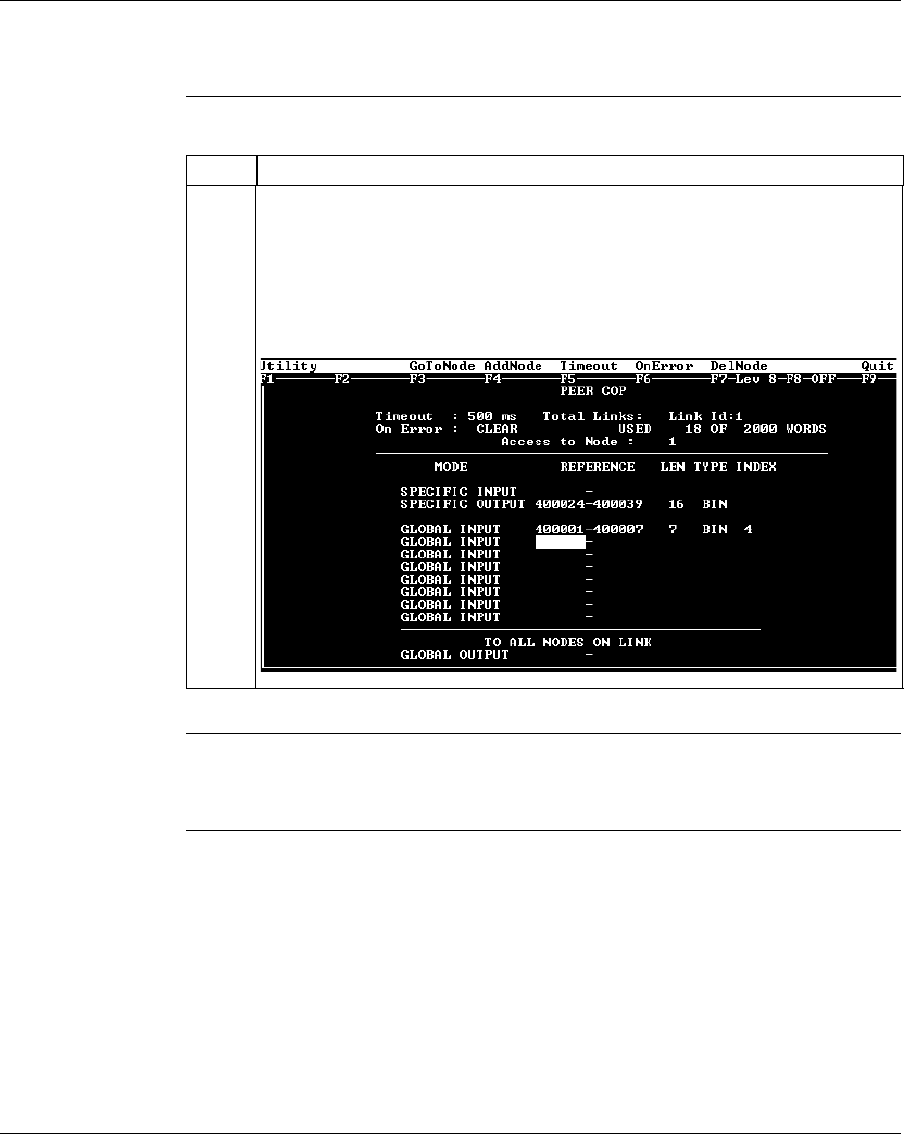
Using Peer Cop with Modsoft
296 870 USE 101 10 V.2
Defining the References for the Next Node, Continued
Defining Global
Inputs, Continued
Next Step Defining references for the supervisory computer.
Step Action
4Type the value 4 in the INDEX column of the GLOBAL INPUT field, indicating
that the M1 CPU at Modbus Plus address 3 will receive the seven words of global
data starting with word 4.
Result: The Peer Cop screen is now set to send 16 words of specific output to the
supervisor at Modbus Plus address 1 and to receive seven words of global data
from the supervisor. The screen should like this:

Using Peer Cop with Modsoft
870 USE 101 10 V.2 297
Defining References for the Supervisory Computer
Overview At this point, we will attach the Modsoft 2.6 programming panel to the AT984
supervisory PLC at Modbus Plus address 1 and set up two Peer Cop screens to
handle the M1 CPUs at addresses 2 and 3.
We know that the M1 at Modbus Plus address 2 is sending eight words of specific
output to the supervisor and that the M1 at Modbus Plus address 3 is sending 16
words of specific output to the supervisor. The supervisor will receive this data as
specific inputs.
We also know that the supervisor is sending 10 words of global data, parts of which
will be received by both of the M1 CPUs.
Accessing
Node 2 Make sure the Link setting is 1 and the Node setting is 2, indicating that the
supervisory computer will exchange data with the CPU at address 2.
Continued on next page
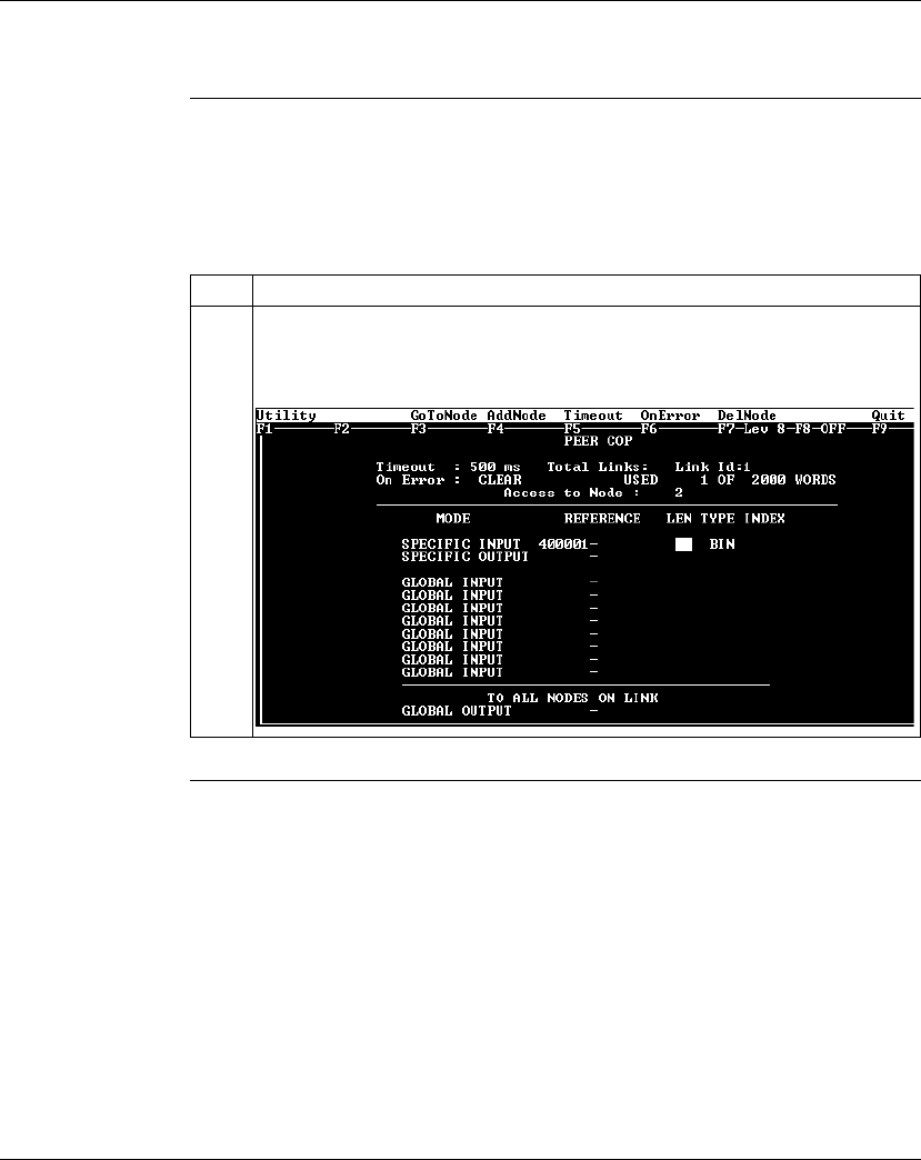
Using Peer Cop with Modsoft
298 870 USE 101 10 V.2
Defining References for the Supervisory Computer, Continued
Specifying
References for
Node 2
We know that this M1 CPU sends eight words of specific output to the supervisor
and receive five words of global data from the supervisor.
Follow the steps in the table below to define the registers that the supervisor will
transmit to and receive from the M1 CPU at Modbus Plus address 2.
Continued on next page
Step Action
1In the REFERENCE column of the SPECIFIC INPUT field, type the value 400001,
the first register which will receive the input. Push <Enter>.
Result: The cursor moves to the LEN column.

Using Peer Cop with Modsoft
870 USE 101 10 V.2 299
Defining References for the Supervisory Computer, Continued
Specifying
References for
Node 2,
Continued
Continued on next page
Step Action
2Type the value 8 in the LEN column of the SPECIFIC INPUT field to indicate the
number of registers that will be received. Push <Enter>.
Result: The REFERENCE field is completed automatically and the cursor moves
to the TYPE column.
3With the TYPE column of the SPECIFIC INPUT filed set to BIN, push <Enter>
twice.
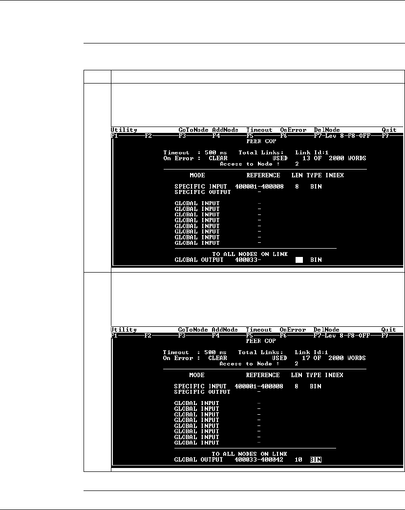
Using Peer Cop with Modsoft
300 870 USE 101 10 V.2
Defining References for the Supervisory Computer, Continued
Specifying
References for
Node 2,
Continued
Continued on next page
Step Action
4In the REFERENCE column of the GLOBAL OUTPUT field (at the bottom of the
screen), type 400033, the first register which will be sent. Push <Enter>.
Result: The cursor moves to the LEN column.
5Type the value 10 in the LEN column of the GLOBAL OUTPUT field to indicate the
number of registers to be sent. Push <Enter>.
Result: The REFERENCE field is completed automatically and the cursor moves to
the TYPE column.

Using Peer Cop with Modsoft
870 USE 101 10 V.2 301
Defining References for the Supervisory Computer, Continued
Specifying
References for
Node 2,
Continued
Next Step Complete the configuration by creating a Peer Cop screen from the supervisor that
accesses node 3 and defines the references for that node.
Step Action
6With the TYPE column of the GLOBAL OUTPUT filed set to BIN, push <Enter>
twice.
Result: The Peer Cop screen should like this:
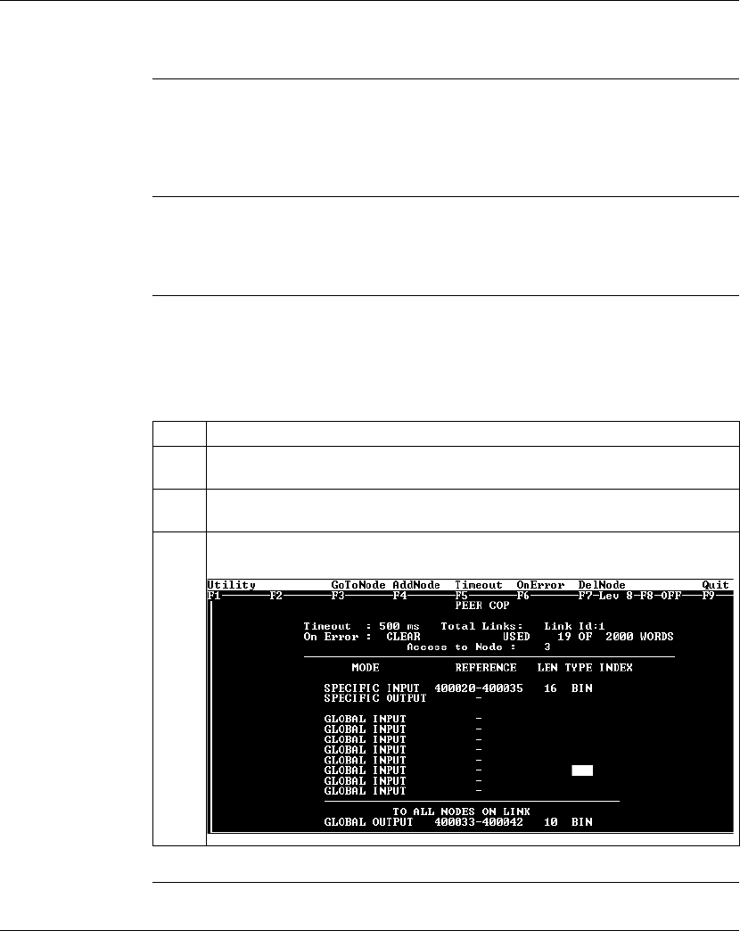
Using Peer Cop with Modsoft
302 870 USE 101 10 V.2
Completing the Configuration
Overview To complete the configuration of the supervisory computer at Modbus Plus address
1, create a Peer Cop screen that accesses the CPU at address 3 and defines the
references for that CPU.
Accessing
Node 3 Using the AddNode command, create a new Peer Cop screen with a Link setting of
1 and a Node setting of 3.
Specifying
References for
Node 3
We know that this M1 CPU sends 16 words of specific output to the supervisor and
receive seven words of global data from the supervisor. Follow the steps in the
table below to define the registers that the supervisor will transmit to and receive
from the M1 CPU at Modbus Plus address 3.
Step Action
1In the REFERENCE column of the SPECIFIC INPUT field, type the value 400020,
the first register which will receive the input. Push <Enter>.
2Type the value 16 in the LEN column of the SPECIFIC INPUT field, indicating the
number of registers that will be received. Push <Enter>.
3The GLOBAL OUTPUT fields should already be complete, since you filled them out
for node 2. The completed Peer Cop screen should look like this:

870 USE 101 10 V.2 303
Saving to Flash in Modsoft
At a Glance
Purpose You save data to Flash so that in the event of an unexpected loss of power, the
application logic and state RAM values will be preserved.
This section describes how to save the application logic and state RAM values to
Flash using Modsoft 2.6.
In This Chapter This chapter contains the following topics:
For This Topic... See Page...
Preparing to Save to Flash 304
Saving to Flash 305

Saving to Flash in Modsoft
304 870 USE 101 10 V.2
Preparing to Save to Flash
Before You Save
to Flash Before you can save to Flash in Modsoft, you need to specify how the controller will
react when power is re-established. This section describes three options. The next
section describes how to specify an option.
Three
Parameters Modsoft will ask you three questions:
Q1 Continue power down Run state? Y/N
Q2 Start PLC after download? Y/N
Q3 Continue? Y/N
Q1 and Q2 define the state of the controller after power is re-established. Q3
simply initiates a save-to-Flash operation in the controller. Q3 cannot be invoked
unless Q1 and Q2 have been answered Y(es) or N(o).
Three Possible
States The following table shows you the three states that you may specify for the
controller:
If the Answer Is ... Then the Controller ...
Q1 = Y Comes back in the state it was in (Running or Stopped) before
power was lost
Q2 = N
Q1 = N Comes back Running when power is restored
Q2 = Y
Q1 = N Comes back Stopped when power is restored
Q2 = N
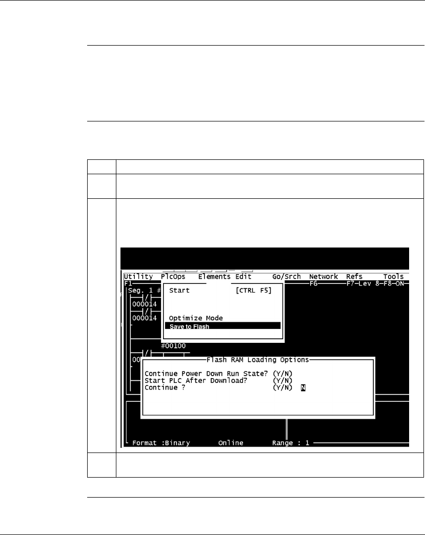
Saving to Flash in Modsoft
870 USE 101 10 V.2 305
Saving to Flash
Conditions for
Saving to Flash In order to save the application program and state RAM values to Flash:
lThe Modsoft panel must be Online
lThe PLC must be stopped (not solving logic)
Save-to-Flash
Procedure Follow the steps below to save to Flash.
Continued on next page
Step Action
1With the PLC online, go to the Ladder diagram editor or the Segment Status
Display.
2From the PlcOps pull-down on the top menu, select Save to Flash.
Result: If the PLC is stopped when you select Save to Flash, the following screen
appears:
3Answer the first two questions to specify the way you want the PLC to restart after a
power-down.
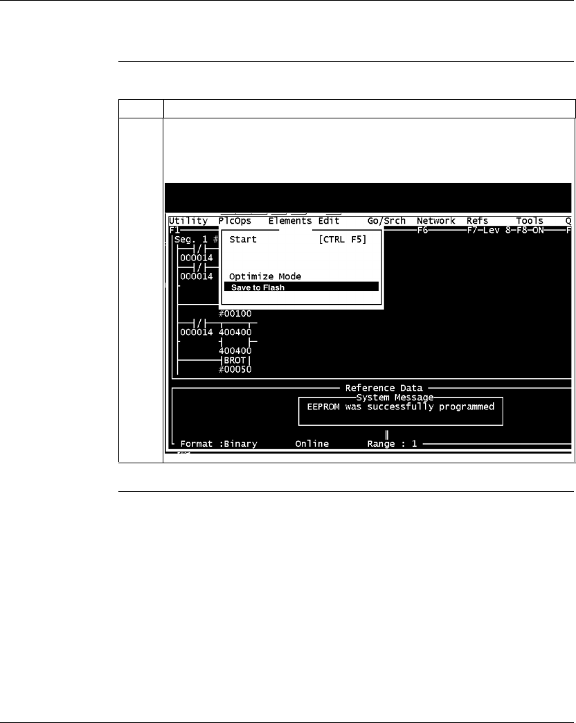
Saving to Flash in Modsoft
306 870 USE 101 10 V.2
Saving to Flash, Continued
Save-to-Flash
Procedure,
Continued Step Action
4Type Y in response to question 3.
Result: The PLC will save your application logic and state RAM table to Flash.
When the save is completed, the following system message appears:

870 USE 101 10 V.2 307
Concept
At a Glance
Purpose This part describes how to configure an M1 CPU, how to I/O map an I/OBus
network, how to configure a Modbus Plus network with Peer Cop and how to save
to Flash using Concept 2.1.
In This Part This part contains the following chapters:
For Information On... See Chapter... On Page...
Configuring an M1 CPU with Concept 12 309
I/O Mapping an I/OBus Network with Concept 13 361
Configuring a Modbus Plus Network in Concept with Peer Cop 14 369
Saving to Flash with Concept 15 399

870 USE 101 10 V.2 309
Configuring an M1 CPU with
Concept
At a Glance
Purpose This chapter explains how to configure a CPU using Concept 2.2.
In This Chapter This chapter contains the following sections:
For This Topic... See Section... On Page...
Configuring the Processor Adapter 1 310
Configuring Option Adapter Features 2 327
Modifying Modbus Port Parameters 3 336
Configuring Ethernet Address Parameters and I/O Scanning 4 344
I/O Mapping the Local I/O Points 5 357

Configuring an M1 CPU with Concept
310 870 USE 101 10 V.2
Section 12.1
Configuring the Processor Adapter
Overview
Purpose This section describes how to configure a Momentum M1 Processor Adapter using
Concept 2.2.
In This Section This section contains the following topics:
For This Topic... See Page...
Selecting an M1 Processor Adapter 311
Default Configuration Parameters 315
Changing the Range of Discrete and Register References 318
Changing the Size of the Full Logic Area 320
Understanding the Number of Segments 321
Changing the Size of the I/O Map 322
Establishing Configuration Extension Memory for Peer Cop 324
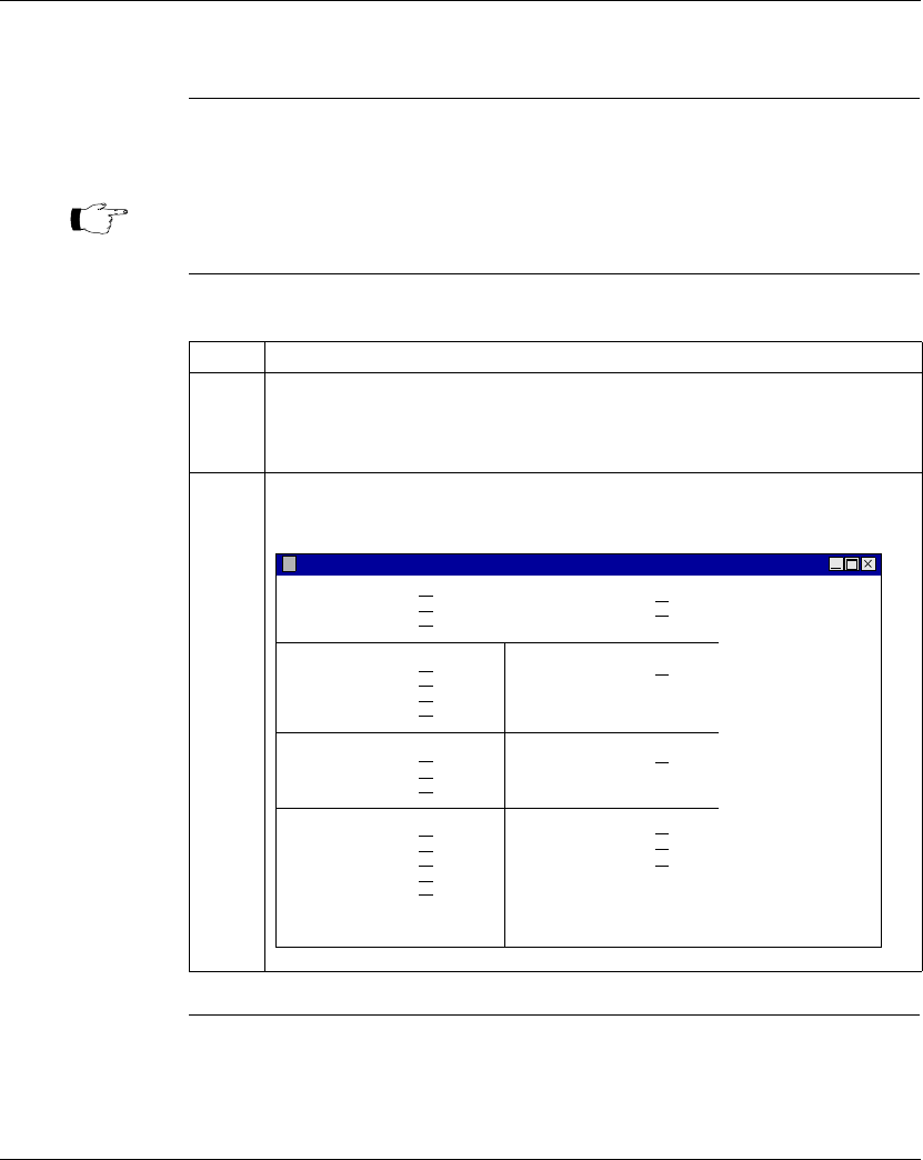
Configuring an M1 CPU with Concept
870 USE 101 10 V.2 311
Selecting an M1 Processor Adapter
Introduction This section describes how to select an M1 Processor Adapter for a new project
using Concept 2.2.
F
Procedure Follow the steps below to select an M1 Processor Adapter for a new project.
Continued on next page
Note: For a full description of Concept, refer to the set of manuals shipped with
the software.
Step Action
1 From the File menu, select New Project.
Result: A new project is opened and the file name [untitled] appears over
the menu bar.
2 From the Project menu, select Configurator.
Result: The PLC Configuration screen appears.
PLC Configuration
PLC
Exec Id:
Memory Size:
Type: Available Logic Area:
Extended Memory:
Ranges Loadables
Specials Segment Scheduler
Config Extensions ASCII
Coils:
Discrete Inputs:
Input Registers:
Holding Registers:
Battery Coil:
Timer Register:
Time of Day:
Data Protection:
Peer Cop:
Hot Standby:
Ethernet:
Profibus DP:
Number installed:
Segments:
Number of Messages:
Mesage Area Size:
Number of Ports:
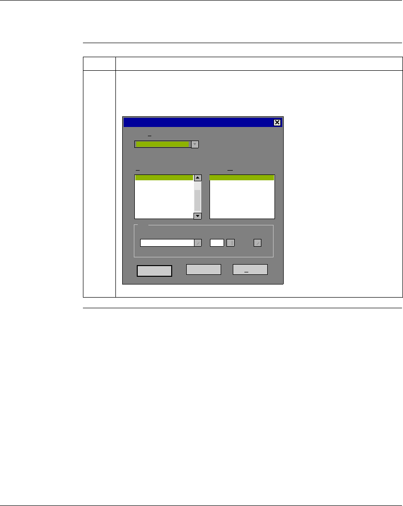
Configuring an M1 CPU with Concept
312 870 USE 101 10 V.2
Selecting an M1 Processor Adapter, Continued
Procedure,
Continued
Continued on next page
Step Action
3 From the Configure menu, select PLC Type OR double-click on the Type field in
the dialog box.
Result: The PLC Selection dialog box appears. The default selection is Quantum.
OK Cancel Help
Not Available
PLC Selection
186 IEC: None 984: Eq/IMIO/CHS
PLC Family:
CPU/Executive: Memory Size:
QUANTUM
140 CPU 113 02 8 K logic / 32 K state
140 CPU 113 02S
140 CPU 113 02X
140 CPU 113 03
140 CPU 113 03S
140 CPU 113 03X
140 CPU 113 04
0

Configuring an M1 CPU with Concept
870 USE 101 10 V.2 313
Selecting an M1 Processor Adapter, Continued
Procedure,
Continued
Continued on next page
Step Action
4 From the PLC Family dropdown menu, select MOMENTUM.
Result: The CPU/Executive menu changes to reflect the choices available for
Momentum.
OK Cancel Help
984 Only
PLC Selection
PROC. ADAPTER,512K, ETHERNET,I/O BUS
PLC Family:
CPU/Executive: Memory Size:
MOMENTUM
18 K logic / 32 K state
0
171 CCC 760 10-984
171 CCC 760 10-IEC
171 CCC 780 10-984
171 CCC 780 10-IEC
171 CCC 960 20-984
171 CCC 980 20-984
171 CCS 700 10
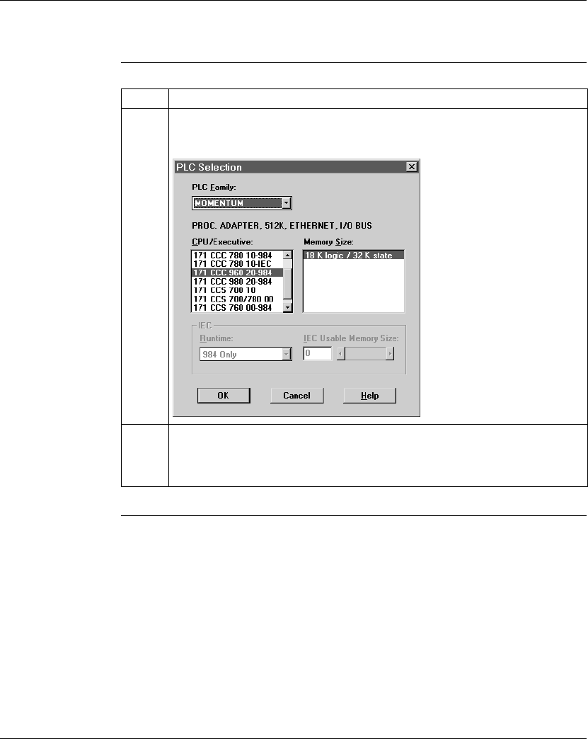
Configuring an M1 CPU with Concept
314 870 USE 101 10 V.2
Selecting an M1 Processor Adapter, Continued
Procedure,
Continued Step Action
5 Choose your PLC type from the CPU/Executive menu.
Result: The remaining fields are filled with corresponding values.
6 Click the <OK> button.
Result: Your PLC type and default configuration parameters are displayed in the
PLC Configuration screen.

Configuring an M1 CPU with Concept
870 USE 101 10 V.2 315
Default Configuration Parameters
Overview This section describes the default configuration parameters.
Defaults for a
2.4K Machine This sample PLC Configuration screen shows the default configuration parameters.
Continued on next page
PLC Configuration PLC
Exec Id:
Memory Size:
Type: Available Logic Area:
Extended Memory:
Ranges Loadables
Specials Segment Scheduler
Config Extensions
Coils:
Discrete Inputs:
Input Registers:
Holding Registers:
Battery Coil:
Timer Register:
Time of Day:
Data Protection:
Peer Cop:
Hot Standby:
Ethernet:
Profibus DP:
Number installed:
Segments: 1
0
1297
Disabled
Not Applicable
Disabled
Not Applicable
Not Applicable
898
2.46K
171 CSS 700 10
000001 - 001536
100001 - 100512
300001 - 300048
400001 - 401872

Configuring an M1 CPU with Concept
316 870 USE 101 10 V.2
Default Configuration Parameters, Continued
Defaults for a
12.2K Machine This sample PLC Configuration screen shows the default configuration parameters.
Continued on next page
PLC Configuration PLC
Exec Id:
Memory Size:
Type: Available Logic Area:
Extended Memory:
Ranges Loadables
Specials Segment Scheduler
Config Extensions
Coils:
Discrete Inputs:
Input Registers:
Holding Registers:
Battery Coil:
Timer Register:
Time of Day:
Data Protection:
Peer Cop:
Hot Standby:
Ethernet:
Profibus DP:
Number installed:
Segments: 1
0
11121
Disabled
Not Applicable
Disabled
Not Applicable
Not Applicable
899
12.29K
171 CSS 760 00-IEC
000001 - 001536
100001 - 100512
300001 - 300048
400001 - 401872

Configuring an M1 CPU with Concept
870 USE 101 10 V.2 317
Default Configuration Parameters, Continued
Defaults for an
18.4K Machine This sample PLC Configuration screen shows the default configuration parameters.
Default Values Here are the default parameters:
PLC Configuration PLC
Exec Id:
Memory Size:
Type: Available Logic Area:
Extended Memory:
Ranges Loadables
Specials Segment Scheduler
Config Extensions
Coils:
Discrete Inputs:
Input Registers:
Holding Registers:
Battery Coil:
Timer Register:
Time of Day:
Data Protection:
Peer Cop:
Hot Standby:
Ethernet:
Profibus DP:
Number installed:
Segments: 1
0
17649
Disabled
Not Applicable
Disabled
Not Applicable
Not Applicable
898
18.43K
171 CCC 960 20-984
000001 - 001536
100001 - 100512
300001 - 300048
400001 - 401872
Parameter 2.4K Machine 12.2K Machine 18.4K Machine
Coils in state RAM 1536 (0
x
) 1536 (0
x
) 1536 (0
x
)
Discrete inputs in state RAM 512 (1
x
) 512 (1
x
) 512 (1
x
)
Input registers in state RAM 48 (3
x
) 48 (3
x
) 48 (3
x
)
Output registers in state RAM 1872 (4
x
) 1872 (4
x
) 1872 (4
x
)
Full logic area (in bytes) 1678 11532 17649
Words of user memory space
for the I/O Map
144 144 144
Memory allocated for
configuration extension
None None None

Configuring an M1 CPU with Concept
318 870 USE 101 10 V.2
Changing the Range of Discrete and Register References
Introduction This section provides guidelines and a procedure for changing the range of discrete
(0
x
and 1
x
) and register (3
x
and 4
x
) references.
Guidelines When you change the range of discrete and register references, follow these
guidelines:
lAdjust the range of discretes in increments of 16. Sixteen discretes consume
one word.
lAdjust the range of registers in increments of 1. Each register consumes one
word.
lThe total number of register and discrete references cannot exceed the
maximum of state memory displayed at the top of the dialog
.
lA minimum configuration of 16 0
x
discretes, 16 1
x
discretes, one 3
x
register,
and one 4
x
register is required.
Continued on next page
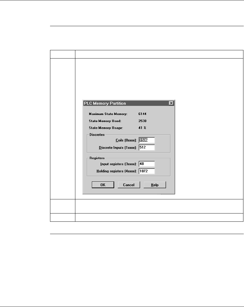
Configuring an M1 CPU with Concept
870 USE 101 10 V.2 319
Changing the Range of Discrete and Register References, Continued
Procedure Follow the steps below to change the range of discrete and register references,
using the PLC Configuration screen:
Step Action
1 From the Configure menu, select Memory Partitions OR double-click on any
field in the Ranges section of the dialog box.
Result: The PLC Memory Partition dialog box appears, showing
the maximum memory size and the register allocation of the CPU.
2 Modify the range of your discrete and register references by changing the value
in the variable boxes, in keeping with the guidelines described above.
3 Click the <OK> button.

Configuring an M1 CPU with Concept
320 870 USE 101 10 V.2
Changing the Size of the Full Logic Area
Introduction The number shown in the Available Logic Area field in the PLC Configuration
screen indicates the total amount of memory available for your application logic.
You cannot directly enter this field to modify the value. You can, however, change
the amount of memory available by manipulating the size of other fields in the PLC
Configuration screen.
Example 1 For example, if you reduce the expansion size of the I/O Map, the number in the
Available Logic Area field automatically increases. Say you are using a 12.2K
machine and you change the size of the I/O Map from 512 to 256, a decrease of
256 words. The Available Logic Area will automatically increase from 1198 to 1454.
Example 2 Similarly, if you allocate some number of words to the Peer Cop expansion size,
you will reduce the Available Logic Area by the number of words allocated for Peer
Cop.

Configuring an M1 CPU with Concept
870 USE 101 10 V.2 321
Understanding the Number of Segments
Only the First
Segment is
Solved
The number of segments specified in the Configuration Overview screen
determines the number of I/O Map drops that you will be able to set up for your
CPU. When you are using Concept 2.2, the default number of segments is 1 in
most CPUs.
This number is adequate for all processor adapters and does not need to be
changed. However, you should only use the second segment for I/OBus I/O
mapping or other subroutines.

Configuring an M1 CPU with Concept
322 870 USE 101 10 V.2
Changing the Size of the I/O Map
Introduction The default size of the I/O Map is 144 words. You may want to adjust this number to
provide more support for an I/OBus network or to increase the size of the full logic
area.
Processors for
I/OBus Networks With I/OBus, an I/O Map table is used to define the number, location and type of
I/O devices on the network bus.
All Other
Processors Other Processor Adapters only use the I/O Map for local I/O. The default of 144
words is more than sufficient for any Momentum I/O base. Depending on the
requirements of your I/O base, you may be able to reduce the number of words to
the minimum, 4, in order to increase the Available Logic Area.
Continued on next page
Default 144 words
Minimum 4 words
Maximum 6143 words, or not to exceed the PLC’s memory size.
Default 144 words
Minimum 4 words
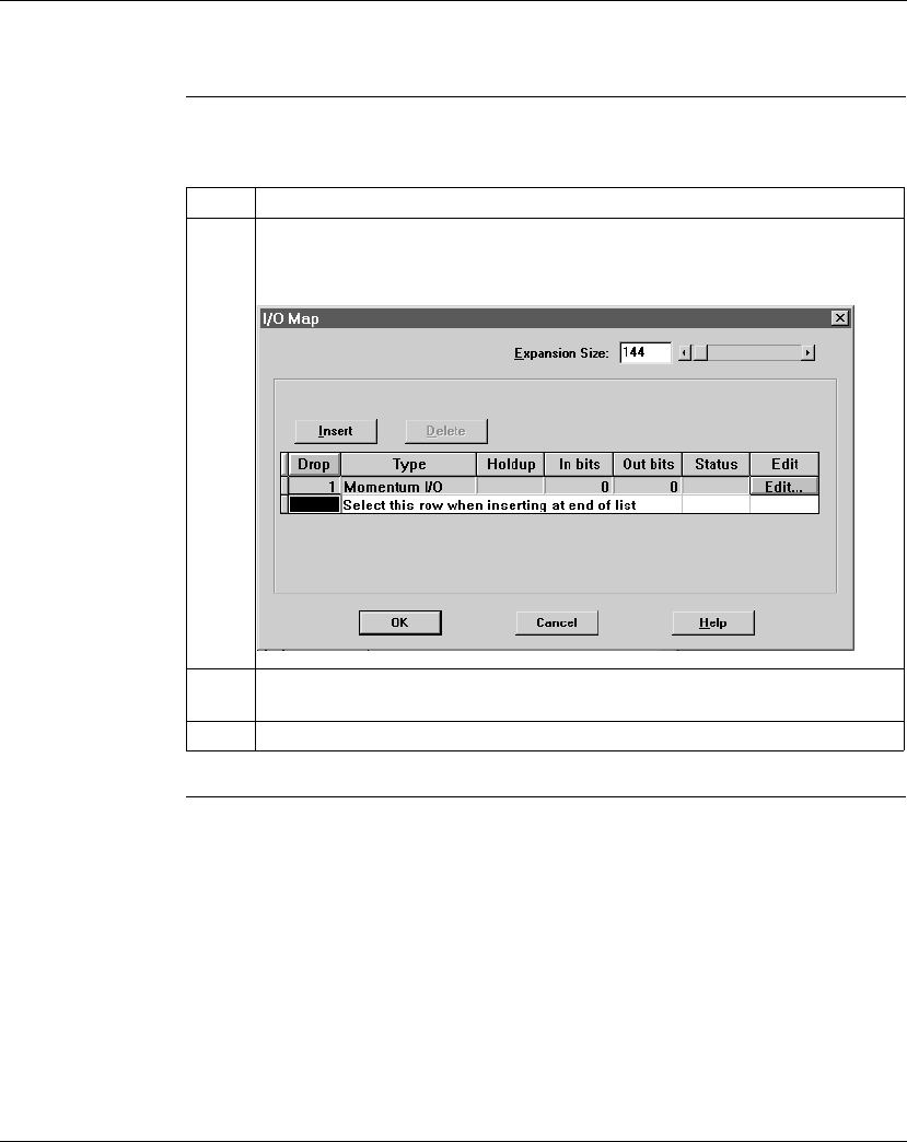
Configuring an M1 CPU with Concept
870 USE 101 10 V.2 323
Changing the Size of the I/O Map, Continued
Procedure From the PLC Configuration screen, follow the steps below to change the size of
the I/O Map:
Step Action
1 From the Configure menu, select I/O Map.
Result: The I/O Map dialog box appears.
2 Modify the size of the I/O Map by typing a new value in the Expansion Size field
OR by adjusting the sliding scale.
3 Click the <OK> button.

Configuring an M1 CPU with Concept
324 870 USE 101 10 V.2
Establishing Configuration Extension Memory for Peer Cop
Introduction By default, the Peer Cop capability is disabled. If you want to use Peer Cop to
handle Modbus Plus communications, you need to enable this capability and adjust
the amount of configuration extension memory.
How Much
Memory? The minimum Peer Cop memory requirement is 20 words; the maximum is 1366
words.
Follow these guidelines for estimating the amount of extension memory you will
need for your Peer Cop database:
Continued on next page
For... Add... Up to a maximum of...
Overhead 9 words --
Global output 5 words --
Global input number of words=
number of devices x
(1 + 2 x number of device subentries)
1088 words
Specific output 2 words for every device entry in Peer Cop 128 words
Specific input 2 words for every device entry in Peer Cop 128 words
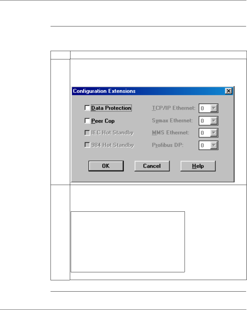
Configuring an M1 CPU with Concept
870 USE 101 10 V.2 325
Establishing Configuration Extension Memory for Peer Cop, Continued
Procedure From the PLC Configuration screen, follow the steps below to enable Peer Cop and
adjust the amount of Configuration Extension memory:
Continued on next page
Step Action
1 From the Configure menu, select Config extensions OR double-click anywhere in
the Config Extensions region of the screen.
Result: The Configuration Extension dialog box appears.
2 Click the check box next to Peer Cop, then click OK.
Result: Peer Cop status changes from Disabled to Enabled in the PLC
Configuration screen.
Data Protection: Disabled
Peer Cop: Enabled
Hot Standby: Not Applicable
Ethernet: 0
Profibus DP: Not Applicable
Config Extensions
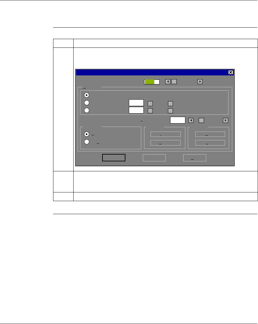
Configuring an M1 CPU with Concept
326 870 USE 101 10 V.2
Establishing Configuration Extension Memory for Peer Cop, Continued
Procedure,
Continued Step Action
3 From the Configure menu, select Peer Cop.
Result: The Peer Cop dialog box appears.
4 Modify the amount of configuration extension memory allocated to Peer Cop by
typing a new value in the Expansion Size field OR by adjusting the sliding scale
next to the field.
5 Click the <OK> button.
0
Peer Cop
100
0
Link 0
Go To Expansion Size:
500Health timeout (msec.):
Last Value Global Specific
Clear on timeout
Hold on timeout
Input...
Output...
Input...
Output...
OK Cancel Help

Configuring an M1 CPU with Concept
870 USE 101 10 V.2 327
Section 12.2
Configuring Option Adapter Features
Overview
Purpose This section describes how to implement the battery backup and time-of-day (TOD)
clock features of the Momentum Option Adapters using Concept 2.2.
In This Section This section contains the following topics:
For This Topic... See Page...
Reserving and Monitoring a Battery Coil 328
Setting up the Time-of-Day Clock 331
Setting the Time 334
Reading the Time-of-Day Clock 335
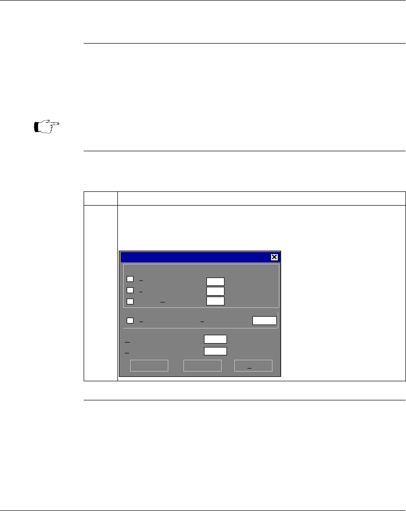
Configuring an M1 CPU with Concept
328 870 USE 101 10 V.2
Reserving and Monitoring a Battery Coil
Introduction Since the Option Adapter does not have an LED to indicate when the battery is low,
we recommend that you reserve a 0
x
reference to monitor the health of the battery.
This section describes how to reserve and monitor a battery coil, using the Specials
dialog box in Concept 2.1.
Reserving a
Battery Coil From the PLC Configuration screen, perform the steps in the following table to
reserve a battery coil.
Continued on next page
Note: The 171 CCC 960 30 and 171 CCC 980 30 require Concept 2.2 with
service release 2.
Step Action
1 From the Configure menu, select Specials... OR double-click on any field in the
Specials region of the dialog box.
Result: The Specials dialog box appears.
Specials
Battery Coil
Timer Register
Time Of Day
0x
4x
4x -400007
1536
1872
1865
Allow Duplicate Coils First Coils Address
Watchdog Timeout (ms*10):
Online Editing Timeslice (ms):
OK Cancel Help
25
20
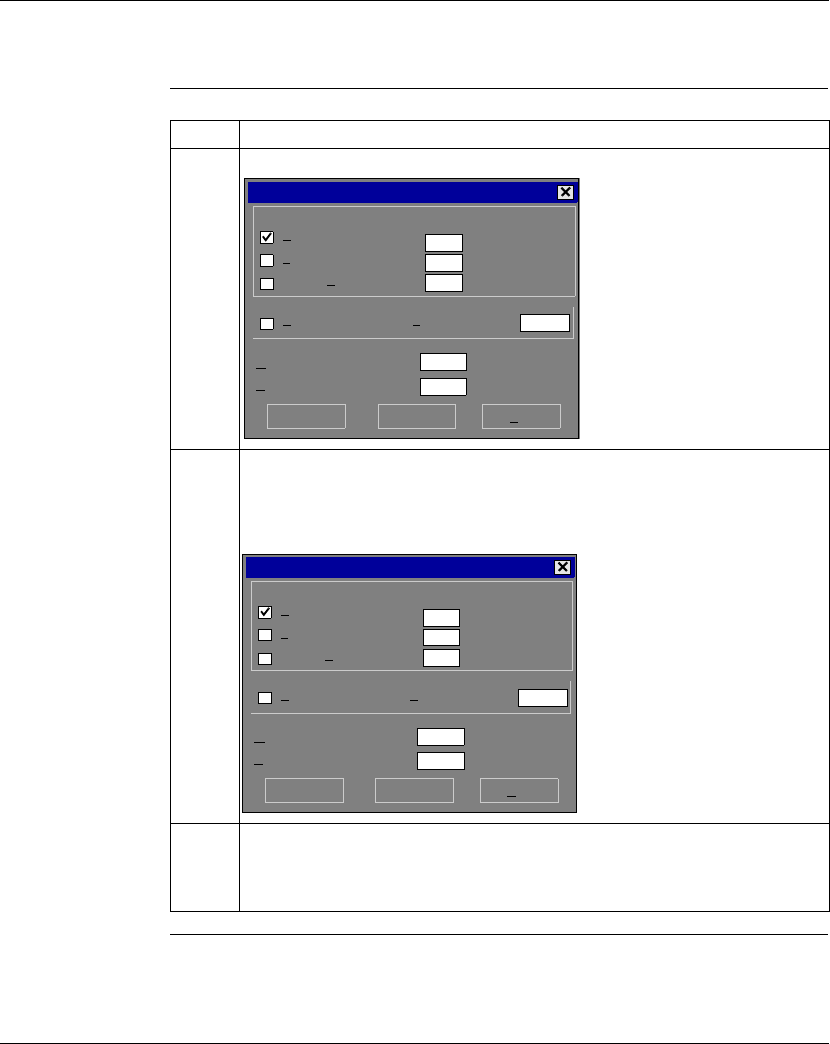
Configuring an M1 CPU with Concept
870 USE 101 10 V.2 329
Reserving and Monitoring a Battery Coil, Continued
Reserving a
Battery Coil,
Continued
Continued on next page
Step Action
2 Click the check box next to Battery Coil.
3 Type a number from the range of available 0
xxxx
references in the box marked
O
x
.
Example: If you have set the range of 0
x
’s at 000001...001536, you might want to
enter the reference value of the last coil–1536.
4 Click the <OK> button.
Result: The dialog box closes and the register you have specified is displayed on
the PLC Configuration screen.
Specials
Battery Coil
Timer Register
Time Of Day
0x
4x
4x -400007
1536
1872
1865
Allow Duplicate Coils First Coils Address:
Watchdog Timeout (ms*10):
Online Editing Timeslice (ms):
OK Cancel Help
25
20
Maximum
Specials
Battery Coil
Timer Register
Time Of Day
0x
4x
4x -400007
1536
1872
1865
Allow Duplicate Coils First Coils Address:
Watchdog Timeout (ms*10):
Online Editing Timeslice (ms):
OK Cancel Help
25
20
Maximum
1536

Configuring an M1 CPU with Concept
330 870 USE 101 10 V.2
Reserving and Monitoring a Battery Coil, Continued
Monitoring the
Battery Coil Monitor the battery coil in ladder logic or tie it to a lamp or alarm that will indicate
when the battery is low.
Interpreting the
Battery Coil The battery coil will always read either 0 or 1.
lA coil state of 0 indicates that the battery is healthy.
lA coil state of 1 indicates that the battery should be changed.
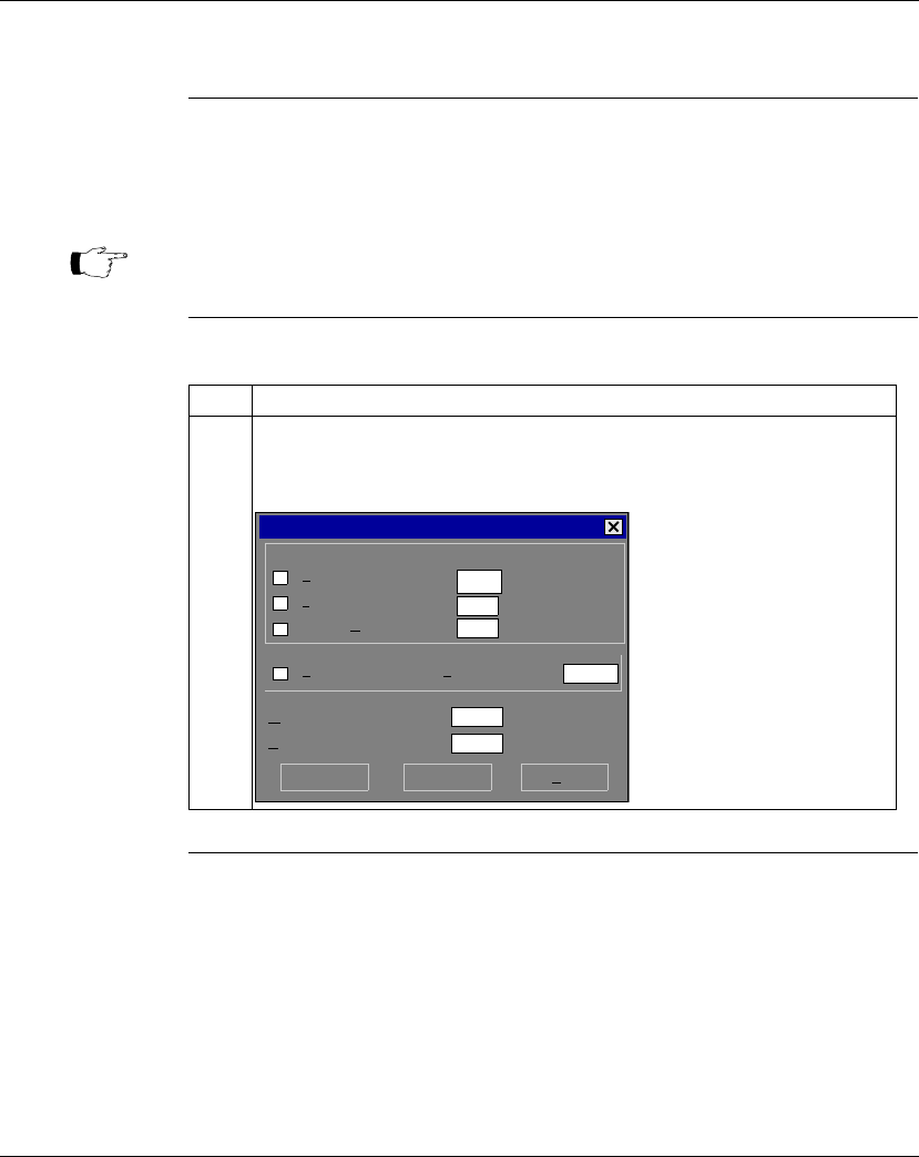
Configuring an M1 CPU with Concept
870 USE 101 10 V.2 331
Setting up the Time-of-Day Clock
Overview Each Option Adapter has a time-of-day clock. To use this feature, you must reserve
a block of eight 4
x
registers.
This section describes how to reserve those registers, using Concept 2.1.
Reserving
Registers for the
TOD Clock
To reserve registers for the TOD clock, perform the steps in the following table.
Continued on next page
Note: The 171 CCC 960 30 and 171 CCC 980 30 require Concept 2.2 with
service release 2.
Step Action
1 From the Configure menu, select Specials... OR double-click on any field in the
Specials region of the dialog box.
Result: The Specials dialog box appears.
Specials
Battery Coil
Timer Register
Time Of Day
0x
4x
4x -400007
1536
1872
1865
Allow Duplicate Coils First Coils Address:
Watchdog Timeout (ms*10):
Online Editing Timeslice (ms):
OK Cancel Help
25
20
Configuring an M1 CPU with Concept
332 870 USE 101 10 V.2
Setting up the Time-of-Day Clock, Continued
Reserving
Registers for the
TOD Clock,
Continued
Continued on next page
Step Action
2 Click the check box next to Time Of Day.
3 Type a number (the first in a series of eight) from the range of available 4
xxxx
references in the corresponding field. Observe the maximum register value.
Example: If you want registers 400100 ... 400107 reserved for the TOD clock,
type 100.
4 Click the <OK> button.
Result: The registers you have specified are displayed on the PLC Configuration
screen.
Specials
Battery Coil
Timer Register
Time Of Day
0x
4x
4x -400007
1536
1872
1865
Allow Duplicate Coils First Coils Address:
Watchdog Timeout (ms*10):
Online Editing Timeslice (ms):
OK Cancel Help
25
20
Maximum
Specials
Battery Coil
Timer Register
Time Of Day
0x
4x
4x -400007
1536
1872
1865
Allow Duplicate Coils First Coils Address:
Watchdog Timeout (ms*10):
Online Editing Timeslice (ms):
OK Cancel Help
25
20
Maximum
100

Configuring an M1 CPU with Concept
870 USE 101 10 V.2 333
Setting up the Time-of-Day Clock, Continued
Next Step Setting the time.
Note: You can use Concept’s Setting the Time feature or use the following
procedure to set the time.

Configuring an M1 CPU with Concept
334 870 USE 101 10 V.2
Setting the Time
Overview Once you have reserved a block of registers for the time-of-day clock, you have to
set the correct time. With Concept, you must go online and set the register bits
individually, using the following guidelines for setting the status bits and setting the
time bits. The CPU must be running.
Setting the
Status Bits The control register (4
x
) uses its four most significant bits to report status:
Setting the Time
Bits The following table shows how the registers handle time-of-day clock data, where
register 4
x
is the first register in the block reserved for the clock:
Note: The time-of-day clock complies with guidelines for the year 2000.
Control Register
12345678910111213141516
1 = error
1 = All clock values have been set
1 = Clock values are being read
1 = Clock values are being set
Note: The time-of-day clock sets itself to zero when it resets while it is running.
Register Data Content
4
x
The control register
4
x
+ 1 Day of the week (Sunday = 1, Monday = 2, etc.)
4
x
+ 2 Month of the year (Jan = 1, Feb = 2, etc.)
4
x
+ 3 Day of the month (1...31)
4
x
+ 4 Year (00...99)
4
x
+ 5 Hour in military time (0...23)
4
x
+ 6 Minute (0...59)
4
x
+ 7 Second (0...59)

Configuring an M1 CPU with Concept
870 USE 101 10 V.2 335
Reading the Time-of-Day Clock
Overview This section uses an example to describe how to interpret the time-of-day clock
registers.
Example If you reserved registers 400100...400107 as your TOD clock registers, set the time
bits, and then read the clock at 9:25:30 on Thursday, July 16, 1998, the registers
would display the following values:
Register Reading Indication
400100 0 1 1 0 0 0 0 0 0 0 0 0 0 0 0 0 All clock values have been set;
clock values are being read
400101 5 (decimal) Thursday
400102 7 (decimal) July
400103 16 (decimal) 16
400104 98 (decimal) 1998
400105 9 (decimal) 9 a.m.
40010 6 25 (decimal) 25 minutes
40010 7 30 (decimal) 30 seconds

Configuring an M1 CPU with Concept
336 870 USE 101 10 V.2
Section 12.3
Modifying Modbus Port Parameters
Overview
Purpose The communication parameters on the Modbus ports are set at the factory. This
section describes how to access the Modbus Port Settings dialog box and edit the
default parameters.
In This Section This section contains the following topics:
For This Topic... See Page...
Accessing the Modbus Port Settings Dialog Box 337
Changing the Baud Rate 338
Changing Mode and Data Bits 339
Stop Bit Should Not Be Changed 340
Changing Parity 340
Changing the Delay 341
Changing the Modbus Address 342
Changing the Protocol on Modbus Port 2 343
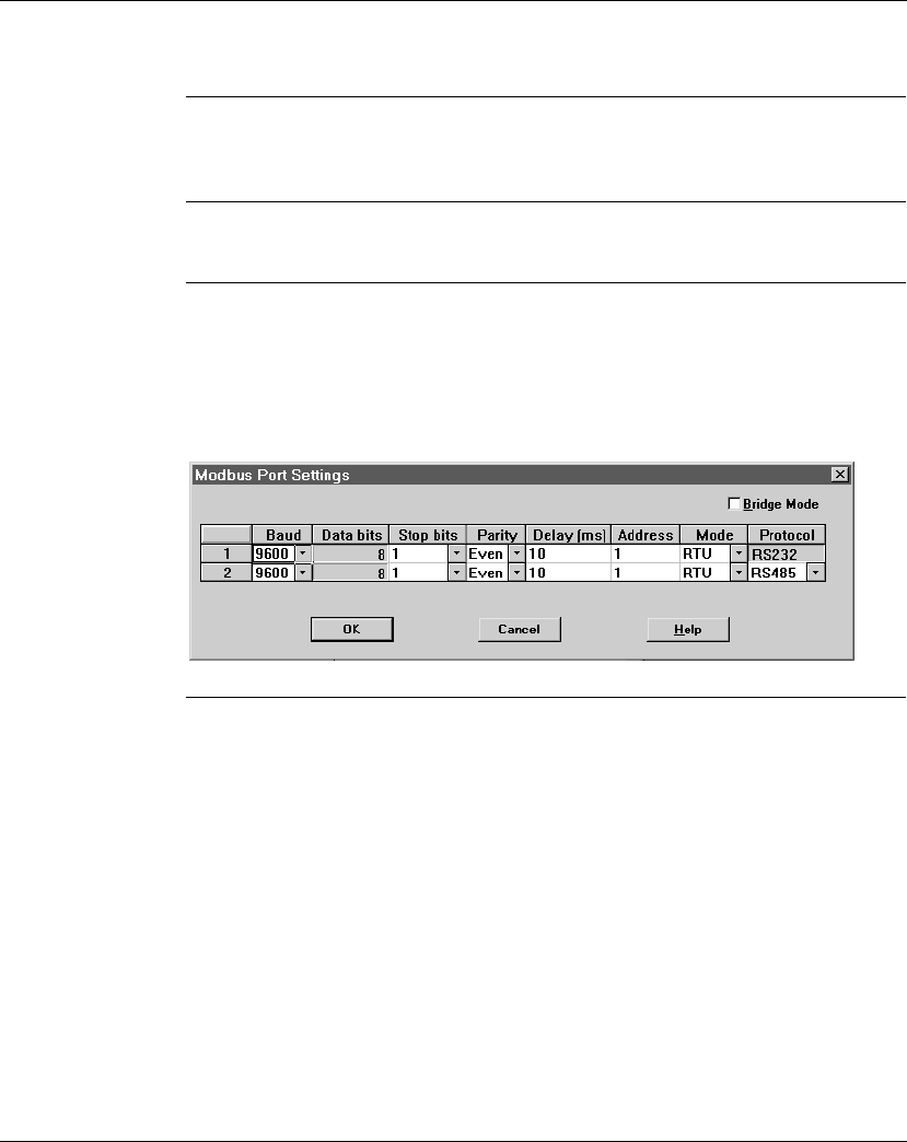
Configuring an M1 CPU with Concept
870 USE 101 10 V.2 337
Accessing the Modbus Port Settings Dialog Box
Introduction Modbus port parameters can be modified using the Modbus Port Settings dialog
box in Concept 2.2.
How to Get There From the Configure menu, select Modbus port settings... .
Modbus Port
Default Settings If you have not previously modified any port parameters, the following dialog box
will appear. The dialog box shows the default parameters for two Modbus ports, 1
and 2, if your system configuration supports two ports.
If you have previously modified any communication port parameters, the new
values will appear in the dialog box.
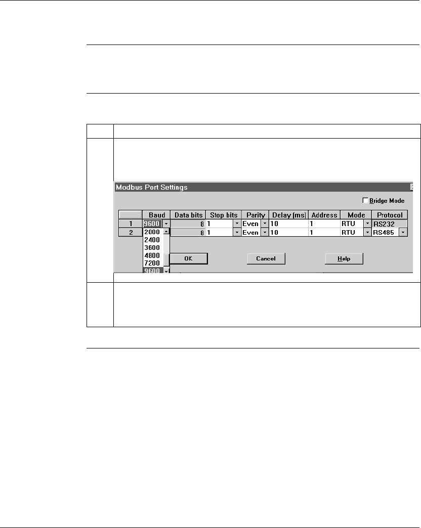
Configuring an M1 CPU with Concept
338 870 USE 101 10 V.2
Changing the Baud Rate
Overview Each port can be configured for a baud in the range 50 ... 19,200. Sixteen valid
baud rates are user-selectable. The factory-set default is 9600 baud.
Procedure To change the baud parameter, perform the steps in the following table.
Step Action
1 Click on the down arrow under the Baud heading.
Result: A menu appears displaying 16 baud values.
2 Click on the desired rate.
Result: The Modbus Port Settings dialog box is updated with the Baud number you
have specified.
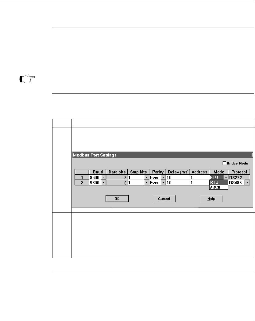
Configuring an M1 CPU with Concept
870 USE 101 10 V.2 339
Changing Mode and Data Bits
Introduction From the Modbus Port Settings dialog box, each port can be configured to operate
in one of two possible modes – RTU or ASCII.
lIf the mode is RTU, the number of data bits is always 8.
lIf the mode is ASCII, the number of data bits is always 7.
Procedure To change the mode and data bit parameters, perform the steps in the following
table.
Note: The factory-set default is 8-bit RTU.
Step Action
1 Click on the down arrow under Mode.
Result: A menu appears displaying your two Mode options.
2 Click on the RTU or ASCII entry.
Result: The Ports setting Window is updated with the Mode type you have
specified, the corresponding Data Bit value appears.
Example: If you change Modbus Port 1 from RTU mode to ASCII mode, the Data
Bit value also automatically changes from 8 to 7.
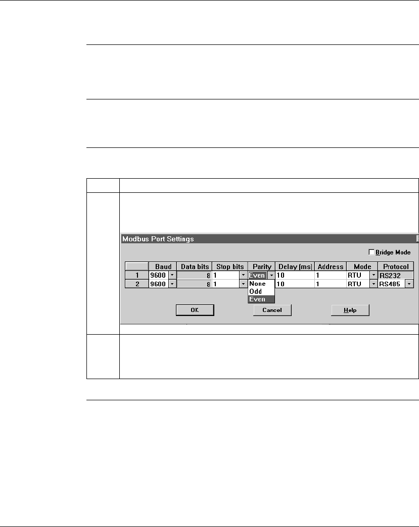
Configuring an M1 CPU with Concept
340 870 USE 101 10 V.2
Stop Bit Should Not Be Changed
Changing Parity
Introduction From the Modbus Port Setting screen, a port can be configured for even, odd, or no
parity checking. The factory-set default is EVEN parity.
Procedure To change the parity parameter, perform the steps in the following table:
Step Action
1 Click on the down arrow under the Parity heading.
Result: A menu appears with the three Parity choices.
2 Click on the None, Odd or Even entry.
Result: The Modbus Port Settings dialog box is updated with the Parity type you
have specified.

Configuring an M1 CPU with Concept
870 USE 101 10 V.2 341
Changing the Delay
Overview The Delay parameter is set to 10 ms and should be left at this value for most
applications. Do not change this parameter unless your application demands it.
If you must change this parameter, you may select a value from 10 ... 1000 ms, in
10 ms increments.
Delay Timing If you use baud rates lower than 4800, adjust the delay timing as indicated in the
following table:
Procedure Follow the steps in the table below to change the delay:
Baud Rate Delay (in Msec)
2400 20
1200 30
600 50
300 100
Step Action
1 Click on the Delay parameter for the port.
2 Type a new value in the range 10 ... 1000 ms, using increments of 10 ms.

Configuring an M1 CPU with Concept
342 870 USE 101 10 V.2
Changing the Modbus Address
Overview Each port can be assigned a Modbus network address in the range 1 ... 247. That
address must be unique with respect to all other device addresses on the same
Modbus networks.
Since Modbus port 1 and Modbus port 2 are always on different Modbus networks,
they can both be assigned the same address value without conflict. The factory-set
default for both ports is address 1.
Procedure From the Modbus Port Settings dialog box, perform the steps in the following table
to change the Modbus Address:
Set the Stop Bit at 1.
Bridge mode is not supported.
Step Address
1 Click on the Address field for the appropriate Modbus port.
2 Type a new value in the range 1 ... 247.
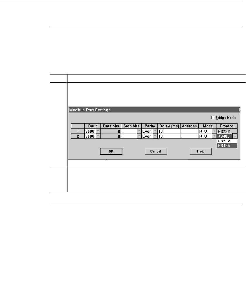
Configuring an M1 CPU with Concept
870 USE 101 10 V.2 343
Changing the Protocol on Modbus Port 2
Overview If your Momentum M1 CPU is using the Modbus Port 2 provided by the
172 JNN 210 32 Option Adapter, you can specify whether it will use the RS232 or
RS485 protocol. The factory-set default for Modbus Port 2 is RS485.
Procedure From the Modbus Port Settings dialog box, perform the steps in the following table
to change the Protocol on Modbus Port 2.
Step Action
1 Click on the down arrow under the Protocol heading.
Result: A menu appears with the two protocol options.
2 Click on RS232 or RS485.
Result: The Modbus Port Settings dialog box is updated with the protocol you have
specified.

Configuring an M1 CPU with Concept
344 870 USE 101 10 V.2
Section 12.4
Configuring Ethernet Address Parameters and I/O Scanning
Overview
Purpose This section describes how to configure the Ethernet port using Concept 2.2,
including IP address, other address parameters and I/O scanning.
In This Section This section contains the following topics:
For This Topic... See Page...
Accessing the Ethernet / I/O Scanner Screen 345
Ethernet Configuration Options 347
Setting Ethernet Address Parameters 348
Configuring I/O 350
Completing the I/O Configuration 354
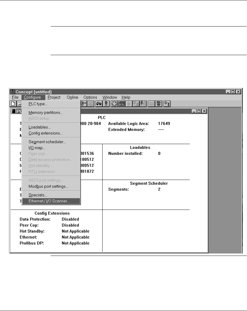
Configuring an M1 CPU with Concept
870 USE 101 10 V.2 345
Accessing the Ethernet / I/O Scanner Screen
Introduction Ethernet address and I/O scanning parameters can be modified using the
Ethernet / I/O Scanner dialog box in Concept 2.2.
How to Get There From the Configure menu, select Ethernet / I/O Scanner... . This menu option will
only be available if you have selected an M1 Processor Adapter with an Ethernet
port.
Continued on next page
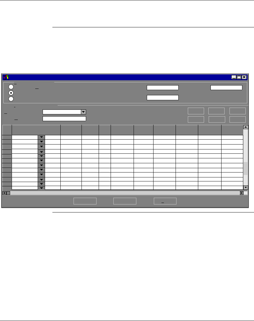
Configuring an M1 CPU with Concept
346 870 USE 101 10 V.2
Accessing the Ethernet / I/O Scanner Screen, Continued
Ethernet Port
Default Settings If you have not previously modified any port parameters, the following dialog box
will appear. The dialog box shows the default parameters for the Ethernet port.
If you have previously modified any communication port parameters, the new
values will appear in the dialog box.
OK Cancel Help
Ethernet / I/O Scanner
171 CCC 960 20-984
Etherner Configuration:
Specify IP Address
Use Bootp Server
Disable Ethernet
I/O Scanner Configuration:
Master Module (slot):
Health Block (1X/3X):
Slave IP Address Unit ID Health
Timeout Rep
Rate Read Ref
Master Read Ref
Slave Read
Length Write Ref
Master Write Ref
Slave De
1
2
3
4
5
6
7
8
9
10
11
12
0.0.0.0
0.0.0.0
255.255.255.0
Configuring an M1 CPU with Concept
870 USE 101 10 V.2 347
Ethernet Configuration Options
Overview The Ethernet / I/O Scanner screen offers three options for configuring the Ethernet
port on an M1 Processor Adapter:
lSpecify IP Address
lUse Bootp Server
lDisable Ethernet
Specify IP
Address This option allows you to type the IP address, gateway and subnet mask in the text
boxes in the upper right-hand corner of the screen.
Use Bootp
Server This is the default. Click this radio button if you want the address parameters to be
assigned by a Bootp server. If you select this option, the address parameter text
boxes in the upper right-hand corner of the screen will be grayed out. They will not
display the actual address parameters.
Disable Ethernet Click this radio button if you want to disable the Ethernet port. Disabling the port will
reduce the scan time for the Processor Adapter.
Ethernet / I/O Scanner
Etherner Configuration:
Specify IP Address
Use Bootp Server
Disable Ethernet
0.0.0.0
0.0.0.0
255.255.255.0
Internet Address:
Gateway:
Subnet Mask :
E
t
h
ernet
/
I/O
S
canner
Etherner Configuration:
Specify IP Address
Use Bootp Server
Disable Ethernet
0.0.0.0
0.0.0.0
255.255.255.0
Note: DISABLING ETHERNET RESULTS IN LOSS OF COMMUNICATIONS.
If you choose the Disable Ethernet option, you will no longer be able to
communicate with the adapter via the Ethernet port. Programming must
then be done via an RS485/232 port or via a Modbus Plus port.
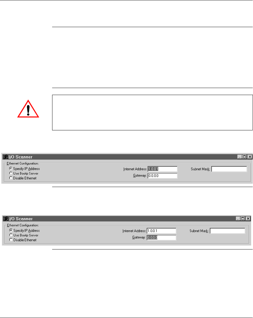
Configuring an M1 CPU with Concept
348 870 USE 101 10 V.2
Setting Ethernet Address Parameters
Overview If you choose to specify the IP address, you should complete all three text boxes in
the upper right-hand corner of the dialog box:
lIP Address
lGateway
lSubnet Mask
IP Address Type a valid IP address in the Internet Address text box, as shown:
Gateway Consult your system administrator to determine the appropriate gateway. Type it in
the Gateway text box, as shown:
Continued on next page
CAUTION
POTENTIAL FOR DUPLICATE ADDRESSES
Obtain a valid IP address from your system administrator to avoid duplication
Failure to observe this precaution can result in injury or equipment damage.
255.255.255.0
255.255.255.0
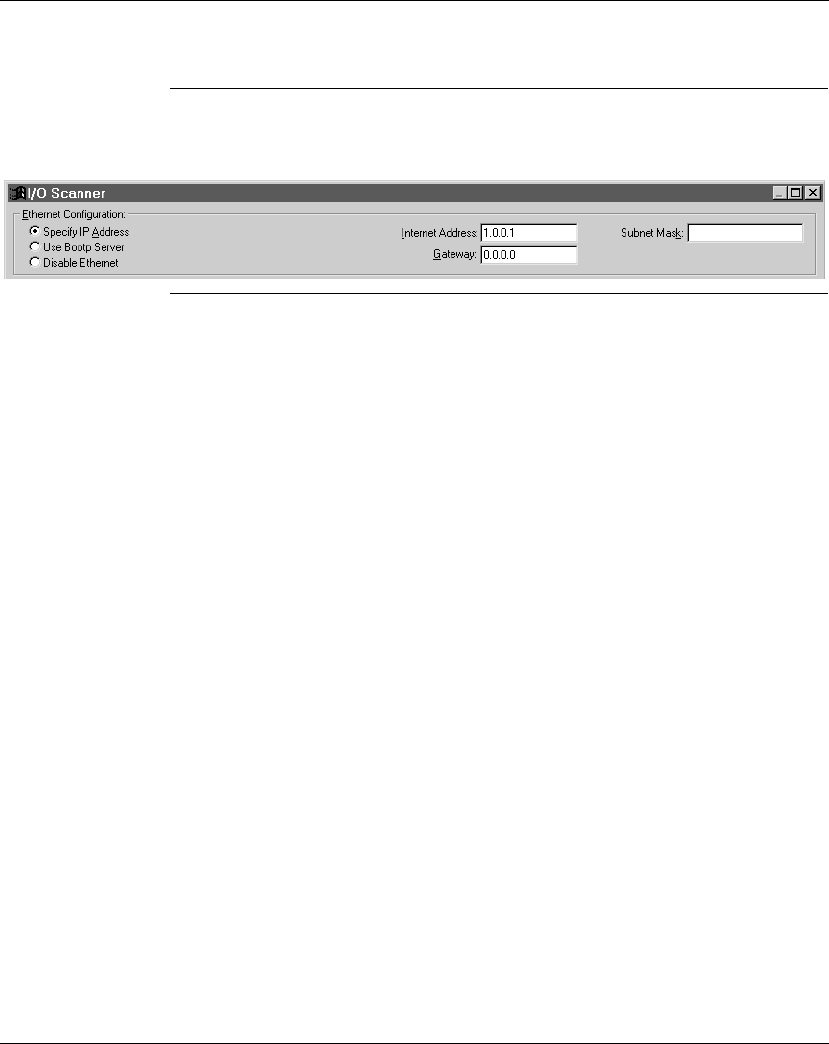
Configuring an M1 CPU with Concept
870 USE 101 10 V.2 349
Setting Ethernet Address Parameters, Continued
Subnet Mask Consult your system administrator to obtain the appropriate subnet mask. Type it in
the Subnet Mask text box, as shown:
255.255.255.0

Configuring an M1 CPU with Concept
350 870 USE 101 10 V.2
Configuring I/O
Overview Once the Ethernet port address parameters have been set, you may assign
parameters for I/O scanning.
Health Block Specify the starting register of the register block which will contain the health bits
for each of the IO Scanner transactions that you intend to configure.
If you designate a 3x register, the health bits for 64 transactions (maximum) will be
stored in 4 contiguous registers starting at the address you specify.
If you designate a 1x register, the health bits will be stored in 64 contiguous
discrete registers.
A health bit is set only if the associated transaction has completed successfully
within the last health timeout period for that transaction (see below). When the PLC
is started, all configured transactions have their respective health bit preset to 1. If
the transaction subsequently fails, then the health bit is cleared after the
programmed health timeout period has expired.
Continued on next page
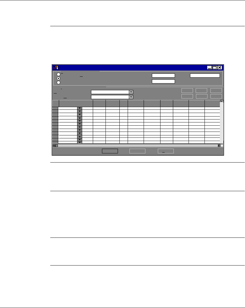
Configuring an M1 CPU with Concept
870 USE 101 10 V.2 351
Configuring I/O, Continued
IP Address Type the IP address of the slave module in the IP address column. This address
will be stored in a pull-down menu, so that you can use it in another row by clicking
on the down arrow and selecting it, as shown:
Unit ID If the slave module is an I/O device attached to the specified slave module, use the
Unit ID column to indicate the device number.
Health Timeout Use this column to specify the length of time in ms to try the transaction before
timing out. Valid values are 0 ... 65,000 ms (1 min). To avoid timing out, specify 0.
If you specify a time, after the specified time without a valid transaction, the health
bit will be reset to zero.
Rep Rate Use this column to specify how often in ms to repeat the transaction. Valid values
are 0 ... 65,000 ms (1 min). To repeat the transaction continually, specify 0.
Continued on next page
OK Cancel Help
Etherner Configuration:
Specify IP Address
Use Bootp Server
Disable Ethernet
I/O Scanner Configuration:
Master Module (slot):
Health Block (1X/3X):
Slave IP Address Unit ID Health
Timeout Rep
Rate Read Ref
Master Read Ref
Slave Read
Length Write Ref
Master Write Ref
Slave De
1
2
3
4
5
6
7
8
9
10
11
12
0.0.0.0
171 CCC 960 20-984
0.0.0.0 255.255.255.0
128.7.32.54
128.7.32.54
128.7.32.54
000 0
000 0
000 0
Ethernet / I/O Scanner
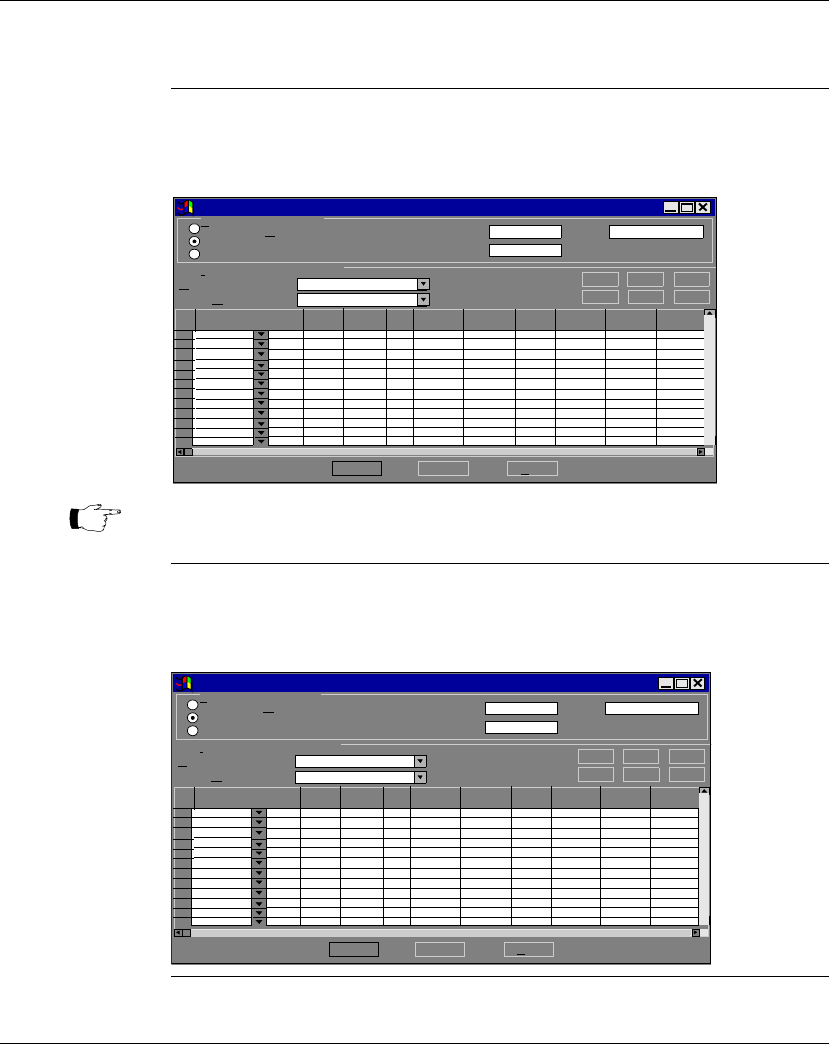
Configuring an M1 CPU with Concept
352 870 USE 101 10 V.2
Configuring I/O, Continued
Read Use the read function to read data from the slave to the master. The Read Ref
Slave column specifies the first address to be read. The Read Count column
specifies the number of registers to read. The Read Ref Master column specifies
the first address to read to.
Write Use the write function to write data from the master to the slave. The Write Ref
Master column specifies the first address to write. The Write Count column
specifies the number of registers to write. The Write Ref Slave column specifies the
first address to write to:
Continued on next page
OK Cancel Help
Etherner Configuration:
Specify IP Address
Use Bootp Server
Disable Ethernet
I/O Scanner Configuration:
Master Module (slot):
Health Block (1X/3X):
Slave IP Address Unit ID Health
Timeout Rep
RateRead Ref
Master Read Ref
Slave Read
Length Write Ref
Master Write Ref
Slave De
1
2
3
4
5
6
7
8
9
10
11
12
0.0.0.0
171 CCC 960 20-984
0.0.0.0 255.255.255.0
128.7.32.54
128.7.32.54
128.7.32.54
000 20
000 0
000 0
Ethernet / I/O Scanner
400001 400050
Note: For Ethernet modules, the Read Ref Slave and Write Ref Slave always
start with register 400001.
OK Cancel Help
Etherner Configuration:
Specify IP Address
Use Bootp Server
Disable Ethernet
I/O Scanner Configuration:
Master Module (slot):
Health Block (1X/
Slave IP Address Unit ID Health
Timeout Rep
Rate Read
Ref Read Ref
Slave Read
Length Write Ref
Master Write Ref
Slave De
1
2
3
4
5
6
7
8
9
10
11
12
0.0.0.0
171 CCC 960 20-984
0.0.0.0 255.255.255.0
128.7.32.54
128.7.32.54
128.7.32.54
000 20
000 0
000 0
Ethernet / I/O Scanner
400100 400040
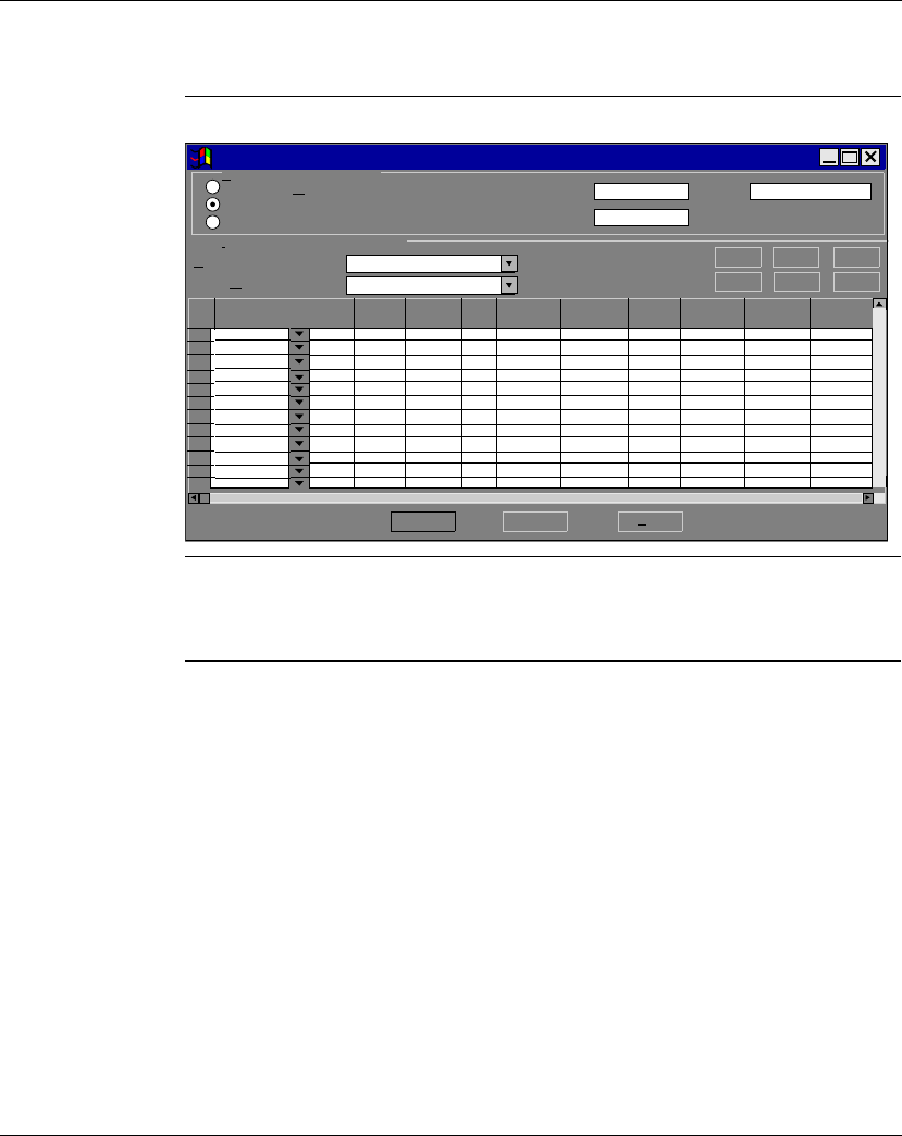
Configuring an M1 CPU with Concept
870 USE 101 10 V.2 353
Configuring I/O, Continued
Read and Write You may include read and write commands on the same line, as shown:
Description You can type a brief description (up to 32 characters) of the transaction in the
Description column.
OK Cancel Help
Etherner Configuration:
Specify IP Address
Use Bootp Server
Disable Ethernet
I/O Scanner Configuration:
Master Module (slot):
Health Block (1X/3X):
Slave IP Address Unit ID Health
Timeout Rep
Rate Read Ref
Slave Read
Length Write Ref
Master Write Ref
Slave De
1
2
3
4
5
6
7
8
9
10
11
12
0.0.0.0
171 CCC 960 20-984
0.0.0.0
255.255.255.0
128.7.32.54
128.7.32.54
128.7.32.54
000 20
000 0
000 0
Ethernet / I/O Scanner
400100 400040
Read Ref
Ma st er
400001 400080

Configuring an M1 CPU with Concept
354 870 USE 101 10 V.2
Completing the I/O Configuration
Introduction This section describes how to complete your Ethernet I/O configuration using the
Copy, Cut, Paste, Delete, Sort and Fill Down buttons.
Copy and Paste To save time when typing similar read and write commands, you may copy and
paste entire rows within your configuration. Follow the steps in the table below:
Continued on next page
Step Action
1 Select the row you want to copy by clicking on the row number at the far left.
2 Click the Copy button above the I/O configuration list.
3 Select the row where you would like to paste the data (by clicking on the row
number at the far left).
4 Click the Paste button above the I/O configuration list.

Configuring an M1 CPU with Concept
870 USE 101 10 V.2 355
Completing the I/O Configuration, Continued
Cut and Paste To move a row within the configuration list, follow the directions for copying, only
use the Cut button instead of the Copy button.
Delete To delete a row from the configuration list, select the row by clicking on the row
number at the far left. Then click the Delete button.
Sort To sort the I/O configuration list, select a column by clicking on the column heading
(i.e. Read Ref Master). Then click the Sort button.
Continued on next page

Configuring an M1 CPU with Concept
356 870 USE 101 10 V.2
Completing the I/O Configuration, Continued
Fill Down To copy part of any row to the next row or to a series of adjoining rows, use the Fill
Down button, following the steps in the table below:
Step Action
1 Use your mouse to select the data you would like to copy and the cells you
would like to copy it to.
Note: You must select one contiguous block of cells, with the data to be copied
in the first row. You cannot select two separate blocks.
2 Click the Fill Down button.
Result: The data from the first row is copied to the selected cells below.

Configuring an M1 CPU with Concept
870 USE 101 10 V.2 357
Section 12.5
I/O Mapping the Local I/O Points
Accessing and Editing the I/O Map
Introduction Every M1 Processor Adapter is assembled on an I/O base. The I/O points on the
base are the local I/O for that processor.
As part of the configuration process, you need to create an I/O Map for the local
I/O. The I/O Map assigns the appropriate range and type of reference values (0
x
,
1
x
, 3
x
, or 4
x
) from the CPU’s state RAM to the input and/or output points on the
local base unit.
Accessing an I/O
Map Screen To access an I/O Map screen from the PLC Configuration screen, select I/O map...
from the Configure menu.
Result: The I/O Map dialog box appears.
Continued on next page
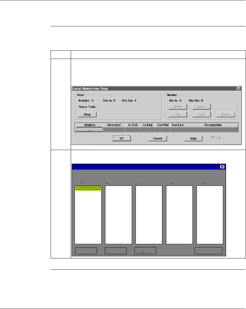
Configuring an M1 CPU with Concept
358 870 USE 101 10 V.2
Accessing and Editing the I/O Map, Continued
Editing the Local
I/O Map From the I/O Map dialog box, perform the steps in the following table to edit the
local I/O Map:
Continued on next page
Step Action
1 Click the Edit... button at the end of the row.
Result: The Local Momentum I/O dialog box appears.
2 Click the button under Module and select your local I/O base from the dropdown
menu.
Description : I/O BASE, ANALOG-8CH DIFFERENTIAL INPUT
I/O Module Selection
OK Help
Cancel Help on Module
Analog I/O Discrete Input Discrete Output Special Other
AAI-030-00 ADI-340-00 ADO-340-00 AEC-920-00
AAI-140-00 ADI-350-00 ADO-350-00
AAI-520-40 ADI-540-50 ADO-530-50
AAO-120-00 ADM-350-1X ADO-540-50
AAO-921-00 ADM-370-10 ADO-730-50
AMM-090-00 ADM-390-10 ADO-740-50
ADM-390-30
ADM-540-80
ADM-690-5X

Configuring an M1 CPU with Concept
870 USE 101 10 V.2 359
Accessing and Editing the I/O Map, Continued
Editing the Local
I/O Map,
Continued
Local I/O Only This screen is always used to I/O Map the local I/O base only. No other I/O base
units can be I/O Mapped on this first screen.
I/O Bus: A
Special Case If you are I/O Mapping a Processor Adapter which supports I/OBus communication
stations, you will need to go to a separate I/O Map screen for Drop 2. That process
is described in
I/O Mapping an I/OBus Network with Concept
on page 361.
Step Action
3 Double-click on your selection or click the <OK> button.
Result: The I/O base you selected is displayed in the Local Momentum Drop
dialog box.
4 Complete any required fields for Input and Output References.
5 Click the <OK> button.

Configuring an M1 CPU with Concept
360 870 USE 101 10 V.2

870 USE 101 10 V.2 361
I/O Mapping an I/OBus Network
with Concept
At a Glance
Purpose This chapter describes how to I/O Map an I/OBus network using Concept 2.2.
Topics This chapter contains the following topics:
For This Topic... See Page...
Supporting an I/O Map for an I/OBus Network 362
Accessing an I/O Map Screen for an I/OBus Network 363
Editing the I/OBus I/O Map 365

I/O Mapping an I/OBus Network with Concept
362 870 USE 101 10 V.2
Supporting an I/O Map for an I/OBus Network
Introduction Three Processor Adapters have an I/OBus communication port that enables them
to control and communicate with other network slave I/O:
l171 CCS 760 00
l171 CCC 760 10
l171 CCC 960 20
l171 CCC 960 30
If you are using I/OBus to control network I/O, you need to write an I/O Map in your
configuration. This section describes the configuration parameters required to
support an I/O Map for I/OBus.
I/O Map
Reserved Words Be sure that you have reserved enough words for I/O mapping to support your I/O
Bus network. The default setting is 144 words. To estimate the number of words
you require, allow:
l16 words for overhead
l10 words/module on the network (including both the local and the network I/O)
Allot sufficient memory to completely I/O Map your network, while preserving as
much user memory as possible for your application program.
Number of
Segments Be sure that the number of segments is set to 2. If you have changed this setting to
1, you will not be able to support an I/OBus network.
Next Step Once you are sure that your Configuration Overview parameters are set properly,
you can access an I/O Map screen for an I/OBus network.
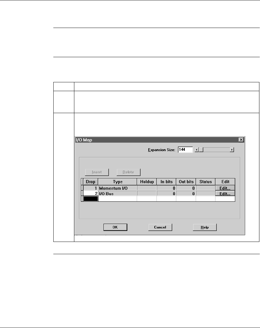
I/O Mapping an I/OBus Network with Concept
870 USE 101 10 V.2 363
Accessing an I/O Map Screen for an I/OBus Network
Overview This section describes how to access an I/O Map screen for an I/OBus network
using Concept 2.2.
Procedure To access the I/O Map screen for your I/OBus network, perform the steps in the
following table.
Continued on next page
Step Action
1 From the Configure menu, select I/OMap.
Result: The I/O Map dialog is displayed.
2 Click on the Insert button.
Result: I/OBus is displayed as the Type for Drop 2.
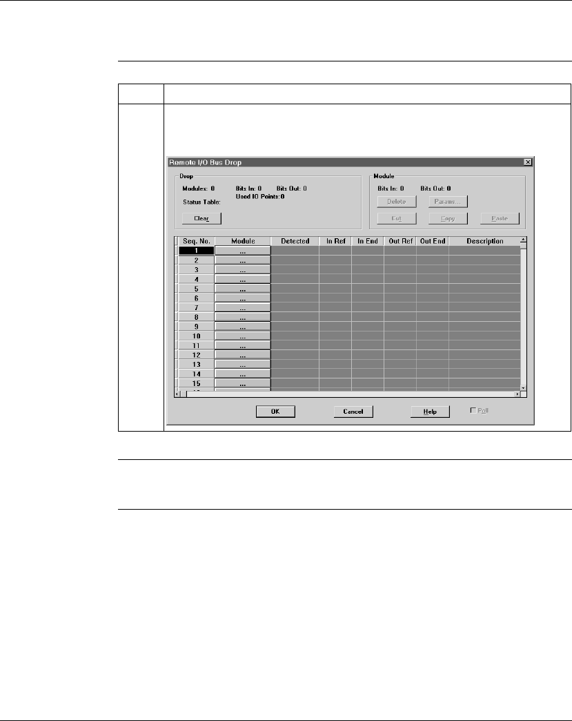
I/O Mapping an I/OBus Network with Concept
364 870 USE 101 10 V.2
Accessing an I/O Map Screen for an I/OBus Network, Continued
Procedure,
Continued
Next Step Editing the I/OBus I/O map.
Step Action
3 Click the Edit... button on the I/OBus line of the I/O Map dialog.
Result: The Remote I/O Bus Drop dialog appears.
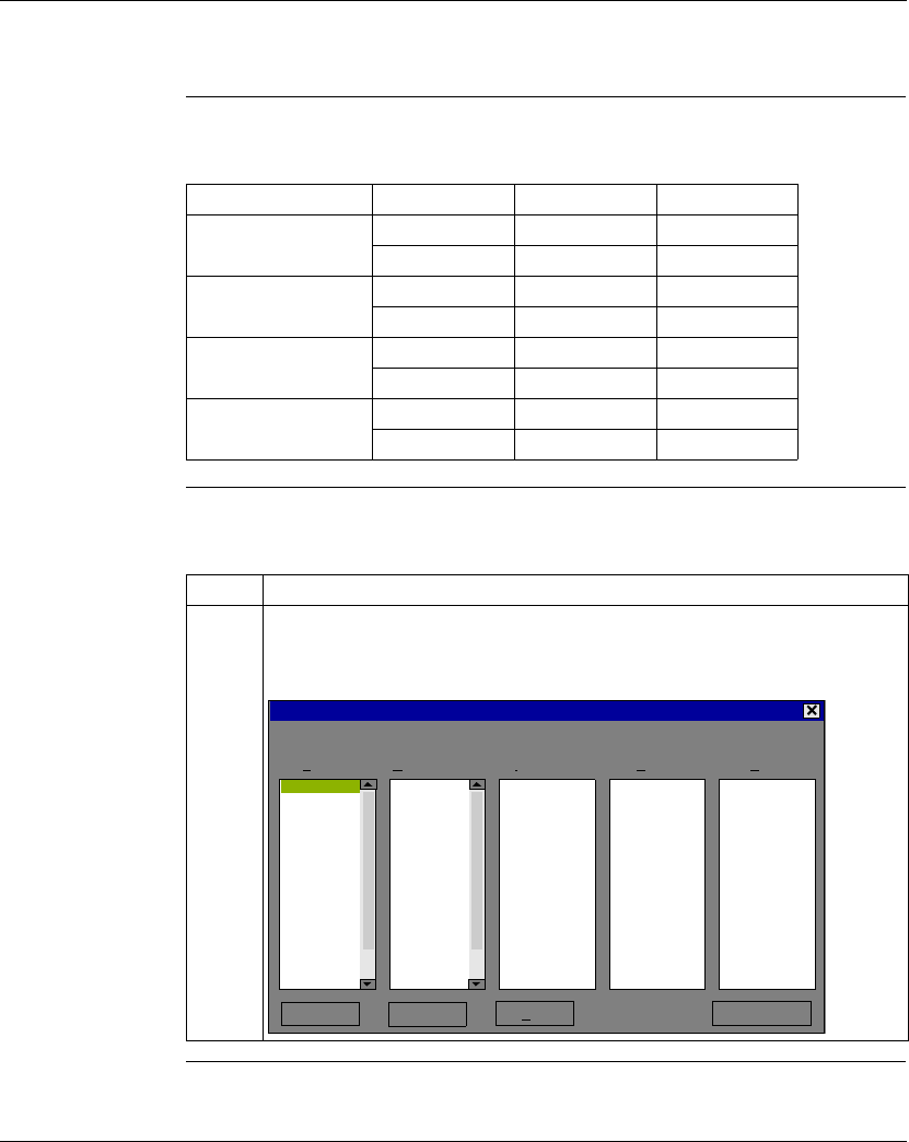
I/O Mapping an I/OBus Network with Concept
870 USE 101 10 V.2 365
Editing the I/OBus I/O Map
Overview The maximum number of modules which can be I/O Mapped on the I/OBus
network depends on your Processor Adapter and its executive:
Procedure To enter I/O bases or Interbus I/O modules using the Remote I/OBus Drop dialog,
perform the steps in the following table.
Continued on next page
Processor Adapter Executive Max. Modules Max. I/O Bits
171 CCS 760 00 984 128 2048
IEC 44 1408
171 CCC 760 10 984 128 2048
IEC 44 1408
171 CCC 960 20 984 256 4096
IEC 128 1408
171 CCC 960 30 984 256 4096
IEC 128 1408
Step Action
1 Click on the button under the Module heading.
Result: A list of module types is displayed, including I/OBus modules identified by
code number (a list of codes is provided at the end of this section):
Description : I/O BASE, ANALOG-8CH DIFFERENTIAL INPUT (Family Type : 0633)
I/O Module Selection
OK Help
Cancel Help on Module
Analog I/O Discrete Input Discrete Output Special Other
AAI-030-00 ADI-340-00 ADO-340-00 AEC-920-00
AAI-140-00 ADI-350-00 ADO-350-00 BNO-6x1-00
AAI-520-40 ADI-540-50 ADO-530-50
AAO-120-00 ADM-350-1X ADO-540-50
AAO-921-00 ADM-370-10 ADO-730-50
AMM-090-00 ADM-390-10 ADO-740-50
IOBUS-0231 ADM-390-30 IOBUS-0101
IOBUS-0232 ADM-540-80 IOBUS-0201
IOBUS-0233 ADM-690-5x IOBUS-0301
IOBUS-0331 IOBUS-0102 IOBUS-0401
IOBUS-0332 IOBUS-0103 IOBUS-0501
IOBUS-0333 IOBUS-0202
IOBUS-0431 IOBUS-0203
IOBUS-0432 IOBUS-0302
IOBUS-0433 IOBUS-0303
IOBUS-0531 IOBUS-0402

I/O Mapping an I/OBus Network with Concept
366 870 USE 101 10 V.2
Editing the I/OBus I/O Map, Continued
Procedure,
Continued
Generic InterBus
Module Identifier
Codes
InterBus device manufacturers embed an identifier code in their network slave
modules in conformance with InterBus standards. The code identifies a device by
its I/O type but not its specific model or name.
I/OBus recognizes the InterBus identifier codes provided below and allows you to
I/O Map devices that use these codes. However, you cannot use the module zoom
screens to define the parameters for these InterBus modules.
Continued on next page
Step Action
2 Click on the desired model number and then click the <OK> button.
Result: The module type and its description are displayed on the Remote I/O Bus
Drop screen. The proper field is enabled so that you can assign state RAM
reference(s) to the unit.
3 Enter the desired reference number. Where there is more than one register the
balance is automatically assigned.
4 Continue to select and map modules one after the other. You must enter the
modules in contiguous node slots on the screen, e.g. you cannot enter a module in
slot 7 if you have not filled slot 6.
Identifier Code I/O Type
IOBUS-0101 One-word discrete output
IOBUS-0102 One-word discrete input
IOBUS-0103 One-word bidirectional
IOBUS-0201 Two-word discrete output
IOBUS-0202 Two-word input
IOBUS-0203 Two-word bidirectional
IOBUS-0231 Two-word analog output
IOBUS-0232 Two-word analog input
IOBUS-0233 Two-word analog bidirectional

I/O Mapping an I/OBus Network with Concept
870 USE 101 10 V.2 367
Editing the I/OBus I/O Map, Continued
Generic InterBus
Module Identifier
Codes, Continued
Identifier Code I/O Type
IOBUS-0301 Three-word discrete output
IOBUS-0302 Three- word input
IOBUS-0303 Three-word bidirectional
IOBUS-0331 Three-word analog output
IOBUS-0332 Three-word analog input
IOBUS-0333 Three-word analog bidirectional
IOBUS-0401 Four-word discrete output
IOBUS-0402 Four-word input
IOBUS-0403 Four-word bidirectional
IOBUS-0431 Four-word analog output
IOBUS-0432 Four-word analog input
IOBUS-0433 Four-word analog bidirectional
IOBUS-0501 Five-word discrete output
IOBUS-0502 Five-word input
IOBUS-0503 Five-word bidirectional
IOBUS-0531 Five-word analog output
IOBUS-0532 Five-word analog input
IOBUS-0533 Five-word analog bidirectional
IOBUS-0633 Eight-word analog bidirectional
IOBUS-1233 16-word analog bidirectional

I/O Mapping an I/OBus Network with Concept
368 870 USE 101 10 V.2

870 USE 101 10 V.2 369
Configuring a Modbus Plus
Network in Concept with Peer
Cop
At a Glance
Purpose Communication transactions over Modbus Plus are defined in Concept 2.1 by a
configuration tool called Peer Cop. This section uses examples to explain how to
use Peer Cop to configure the two types of network architecture:
lAn I/O network, where the Peer Cop of the CPU defines all the communication
transactions over the full network.
lA supervisory network with two or more CPUs communicating with each other
and with additional devices on the network.
In This Chapter This chapter contains the following sections:
Note: The 171 CCC 960 30 and 171 CCC 980 30 require Concept 2.2 with
service release 2.
For This Topic... See Section... On Page...
Getting Started 1 370
Using Modbus Plus to Handle I/O 2 376
Passing Supervisory Data over Modbus Plus 3 387

Configuring a Modbus Plus Network in Concept with Peer Cop
370 870 USE 101 10 V.2
Section 14.1
Getting Started
Overview
Purpose This section explains how to access the Peer Cop Configuration Extension screen
and describes the default screen.
In This Section This section contains the following topics:
For This Topic... See Page...
Accessing the Peer Cop Dialog Box 371
Adjusting the Amount of Extension Memory 373
Other Default Settings in the Peer Cop Dialog Box 374
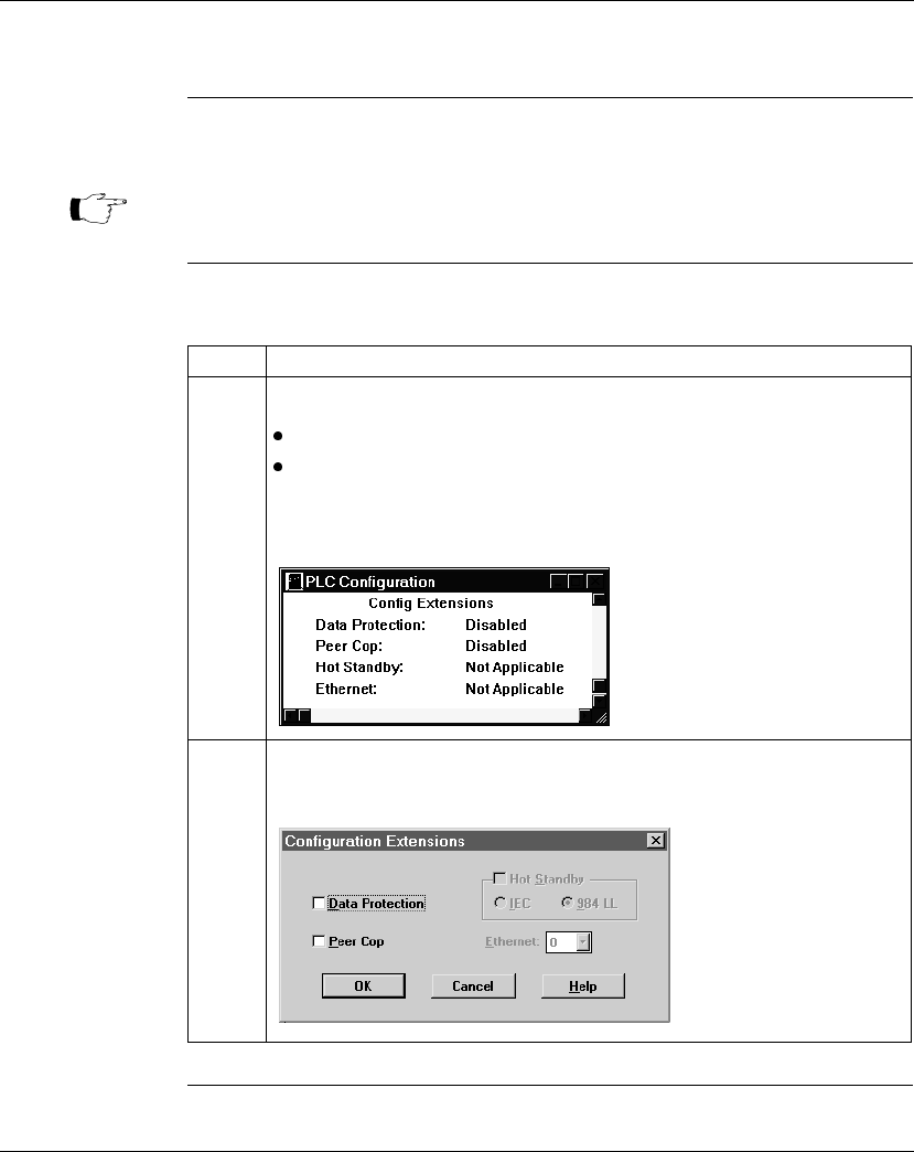
Configuring a Modbus Plus Network in Concept with Peer Cop
870 USE 101 10 V.2 371
Accessing the Peer Cop Dialog Box
Introduction This section describes how to access the Peer Cop dialog box in Concept 2.1.
Accessing the
Screen Follow the steps below to access the Peer Cop from the PLC Configuration Screen.
Continued on next page
Note: The 171 CCC 960 30 and 171 CCC 980 30 require Concept 2.2 with
service release 2.
Step Action
1 Check the status of Peer Cop.
If Peer Cop is enabled, jump to step 4.
If Peer Cop is disabled, continue with step 2.
Example: The Peer Cop status is reported in the Configuration Extensions
section of the PLC Configuration Screen. Here Peer Cop is disabled:
2 Double-click on the Peer Cop field.
Result: The Configuration Extension dialog box appears.
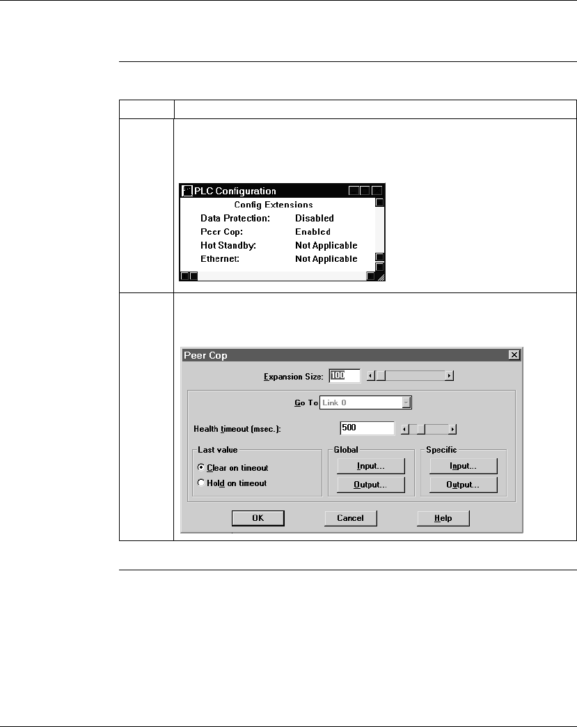
Configuring a Modbus Plus Network in Concept with Peer Cop
372 870 USE 101 10 V.2
Accessing the Peer Cop Dialog Box, Continued
Accessing the
Screen,
Continued Step Action
3 Click the check box next to Peer Cop, then click OK.
Result: Peer Cop status changes from Disabled to Enabled in the PLC
Configuration screen.
4 Select Peer Cop from the Configure menu.
Result: The Peer Cop dialog box appears.

Configuring a Modbus Plus Network in Concept with Peer Cop
870 USE 101 10 V.2 373
Adjusting the Amount of Extension Memory
Introduction The default amount of memory allotted for Configuration Extension is 100 words.
This amount may be adjusted within the Peer Cop dialog box.
Extension
Memory Size The minimum Peer Cop memory requirement is 20 words; the maximum is 4041
words.
Estimating How
Much Memory to
Reserve
Follow these guidelines for estimating the amount of extension memory you will
need for your Peer Cop database:
Changing the
Amount of
Memory
Type the desired size in the Expansion Size text box or use your mouse to adjust
the button on the horizontal slider.
For... Add... Up to a maximum of...
Overhead 9 words --
Global output 5 words --
Global input number of words=
number of devices x
(1 + 2 x number of device subentries)
1088 words
Specific output 2 words for every device entry in Peer Cop 128 words
Specific input 2 words for every device entry in Peer Cop 128 words
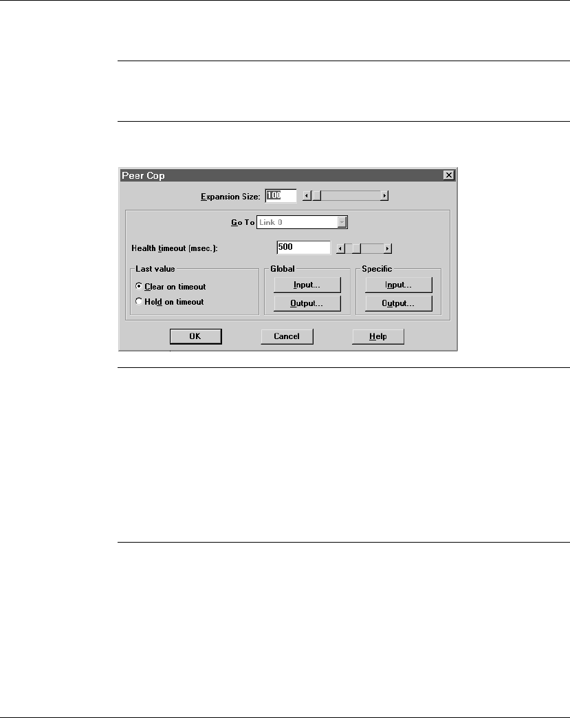
Configuring a Modbus Plus Network in Concept with Peer Cop
374 870 USE 101 10 V.2
Other Default Settings in the Peer Cop Dialog Box
Overview This section describes the default settings for Health Timeout and Last Value.
Diagram The first time you access the Peer Cop dialog box, the following screen appears:
Health Timeout The default Timeout is 500 ms.
Timeout
is the maximum interval that Modbus Plus on a Peer-Copped device will
remain healthy without communication activity. If this interval is exceeded, the
device will clear its network health bit and will no longer try to communicate via
Modbus Plus.
The timeout interval must be in the range 20...2000 ms, and it must be specified as
an increment of 20 ms.
Continued on next page

Configuring a Modbus Plus Network in Concept with Peer Cop
870 USE 101 10 V.2 375
Other Default Settings in the Peer Cop Dialog Box, Continued
Last Value The default Last Value setting is Clear on timeout. This setting specifies how a
peer-copped device will treat the last values received before a timeout, once
Modbus Plus communications have been restored.
Option Effect
Clear on timeout Sets all values received before timeout to 0.
Hold on timeout Retains the values received before timeout.

Configuring a Modbus Plus Network in Concept with Peer Cop
376 870 USE 101 10 V.2
Section 14.2
Using Modbus Plus to Handle I/O
Overview
Purpose This section uses an example to explain how to configure a Modbus Plus network
for I/O servicing. In this example, a CPU will control four Momentum I/O modules.
In This Section This section contains the following topics:
For This Topic... See Page...
Devices on the Network 377
Changing the Peer Cop Summary Information 378
Specifying References for Input Data 380
Specifying References for Output Data 384

Configuring a Modbus Plus Network in Concept with Peer Cop
870 USE 101 10 V.2 377
Devices on the Network
Introduction This section describes the five devices which comprise the sample network and the
strategy used to assign addresses.
The Network
Devices The following table lists the Modbus Plus address and components of each
Momentum module on the network:
Address
Strategy In this type of architecture, assign the lowest network address (1) to the CPU.
When the network initializes, the CPU will be the first device to get the token, and
the token rotation table will be built with respect to the controlling device on the
network.
Modbus Plus
Address I/O Base Type Adapter Type
1 (type not specified) M1 Processor Adapter
(type not specified)
172 PNN 210 22
Modbus Plus Option Adapter
2 170 ADI 340 00
16-point input
170 PNT 110 20
Modbus Plus Communication Adapter
3 170 ADO 340 00
16-point output
170 PNT 110 20
Modbus Plus Communication Adapter
4 170 ADI 350 00
32-point input
170 PNT 110 20
Modbus Plus Communication Adapter
5 170 ADO 350 00
32-point output
170 PNT 110 20
Modbus Plus Communication Adapter
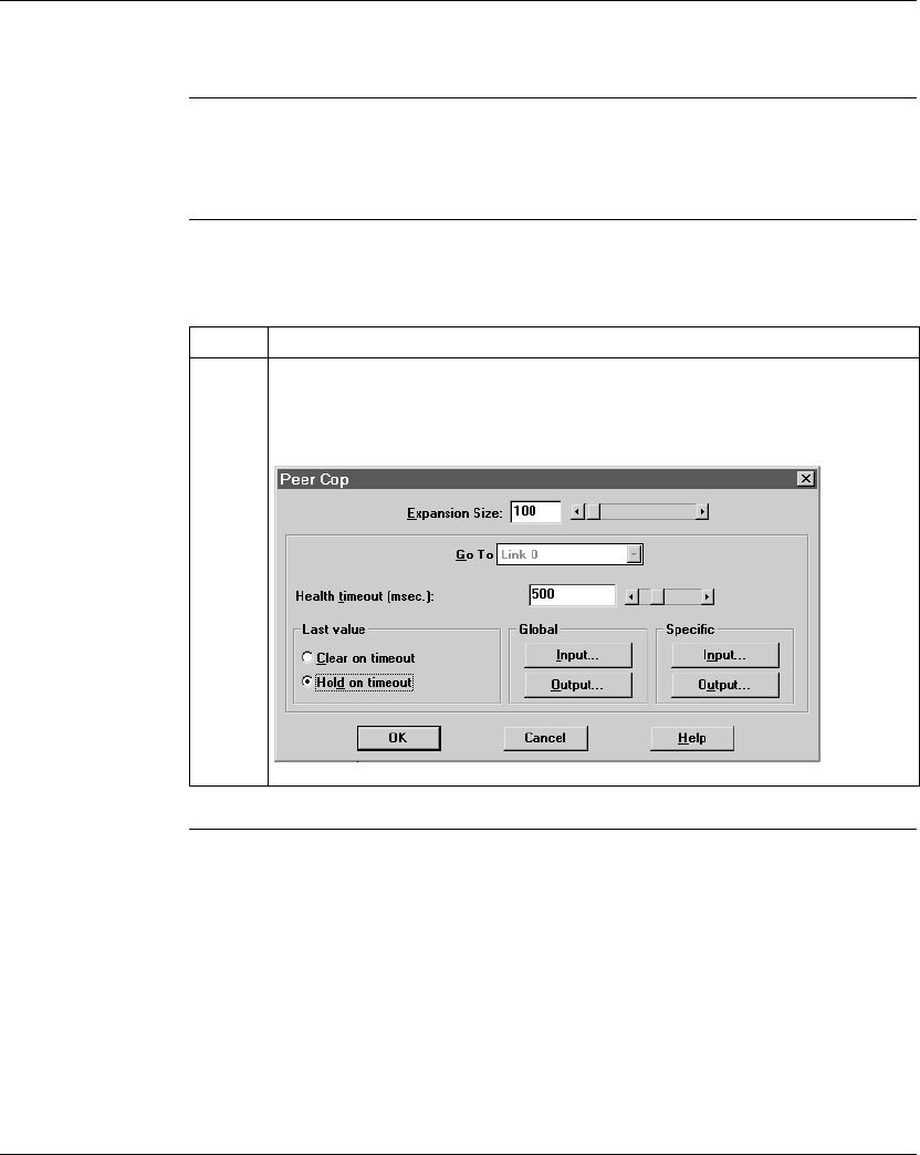
Configuring a Modbus Plus Network in Concept with Peer Cop
378 870 USE 101 10 V.2
Changing the Peer Cop Summary Information
Overview For our example, we will change the default Health Timeout setting to 240 ms and
the default Last Value setting to Hold on timeout.
Procedure Follow the steps in the table below to change the default values, using the Peer
Cop dialog box.
Continued on next page
Step Action
1 Click the Hold on Timeout radio button.
Result: The Hold on Timeout option is selected and the Clear on Timeout option is
deselected.
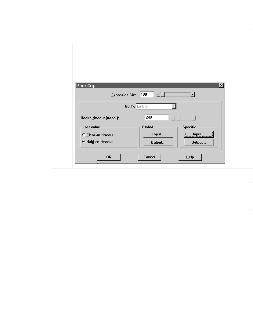
Configuring a Modbus Plus Network in Concept with Peer Cop
870 USE 101 10 V.2 379
Changing the Peer Cop Summary Information, Continued
Procedure,
Continued
Next Step Specifying references for input data.
Step Action
2 Select the Health Timeout default value (500) with your mouse and type the new
value (240) in its place OR use the horizontal slider to change the value.
Result: The new Health Timeout value is 240.

Configuring a Modbus Plus Network in Concept with Peer Cop
380 870 USE 101 10 V.2
Specifying References for Input Data
Introduction This section describes how to specify the references for input data. In this example,
you will start by accessing the device at Modbus Plus address 2, which is a 170
ADI 340 00 16-point input module.
Device
Requirements When you use Peer Cop to handle a Modbus Plus I/O architecture, you need to be
aware of the type of I/O you are configuring at each network address. Peer Cop
does not know that the device at address 2 is a discrete 16-point input module. You
need to know that a specific input reference with a length of one word (16 bits) is
required to handle this module.
We will assign a 3
x
register (300016) as a specific input to the CPU. When the 170
ADI 340 00 sends input data to the CPU, it will be sent to this register.
Continued on next page
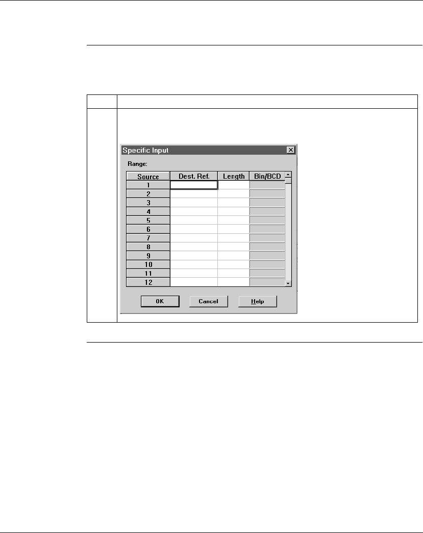
Configuring a Modbus Plus Network in Concept with Peer Cop
870 USE 101 10 V.2 381
Specifying References for Input Data, Continued
Procedure Follow the steps in the table below to define the specific input, starting from the
Peer Cop dialog box.
Continued on next page
Step Action
1 Click on the Specific Input... button.
Result: The Specific Input dialog box appears.
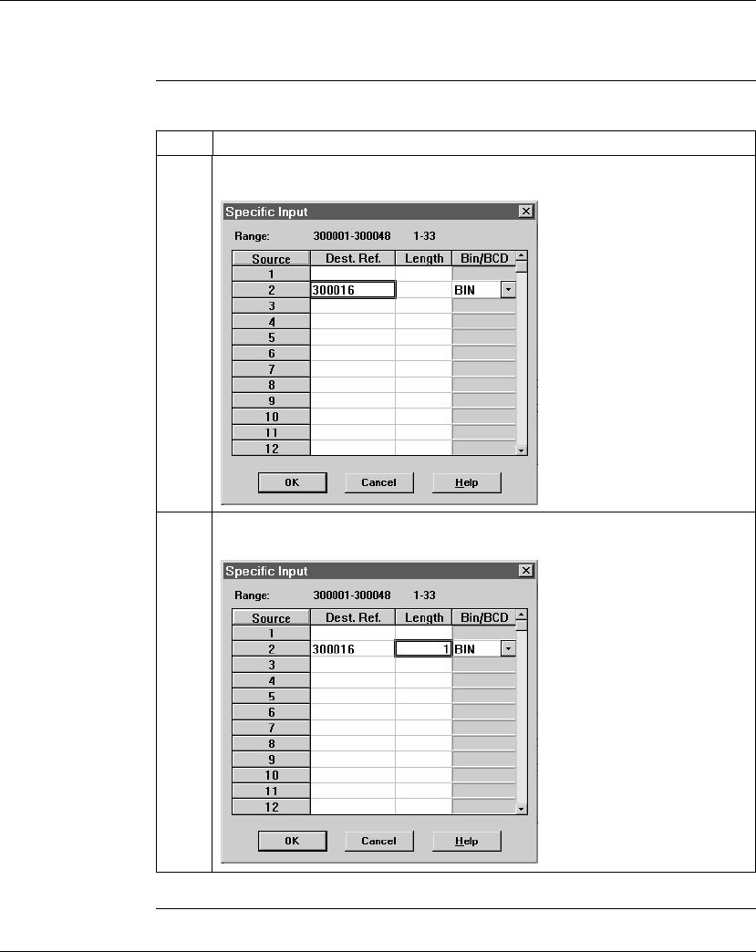
Configuring a Modbus Plus Network in Concept with Peer Cop
382 870 USE 101 10 V.2
Specifying References for Input Data, Continued
Procedure,
Continued
Continued on next page
Step Action
2 Since you are addressing the device at address 2, you will use the line for Source
2. Type the value 300016 on that line in the Dest. Ref. column.
3 Type the value 1 in the Length column, indicating that the device at address 2 will
exchange one word of data. In this case, we will leave the default BIN setting.
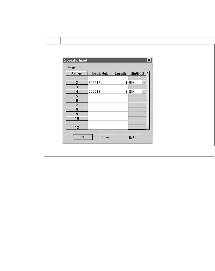
Configuring a Modbus Plus Network in Concept with Peer Cop
870 USE 101 10 V.2 383
Specifying References for Input Data, Continued
Procedure,
Continued
Next Step Specifying output references.
Step Action
4 Repeat steps 2 and 3 for the device at address 4, using the settings in the figure
below. Then click <OK>.
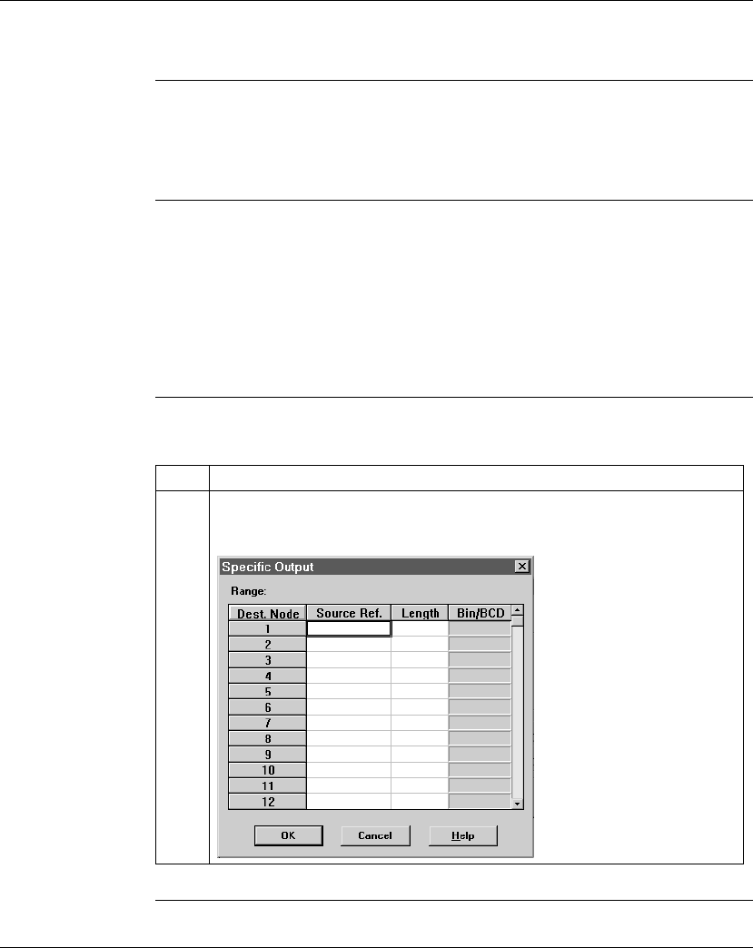
Configuring a Modbus Plus Network in Concept with Peer Cop
384 870 USE 101 10 V.2
Specifying References for Output Data
Introduction This section describes how to specify the references for output data. In this
example, you will start by accessing the device at Modbus Plus address 3, which is
a 170 AD0 340 00 16-point output module.
Device
Requirements When you use Peer Cop to handle a Modbus Plus I/O architecture, you need to
know which type of I/O you are configuring at each network address and how many
input or output references each device requires. In this example, we will create a
specific output reference with a length of one word (16 bits).
We also will assign a 4
x
register (400016) as a specific input to the CPU. When the
the 170 ADO 340 00 sends input data to the CPU, it will be sent to this register.
Procedure Follow the steps in the table below to define the specific output.
Continued on next page
Step Action
1 Click on the Specific Output... button in the Peer Cop dialog box.
Result: The Specific Output dialog box appears.
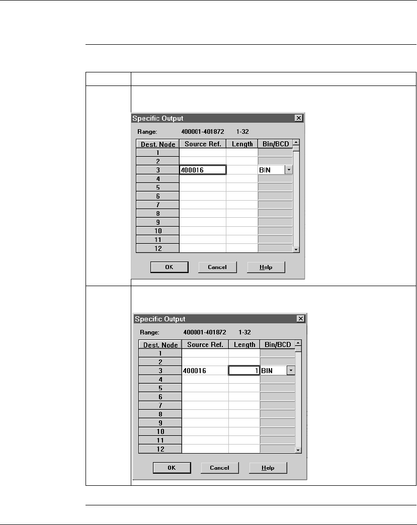
Configuring a Modbus Plus Network in Concept with Peer Cop
870 USE 101 10 V.2 385
Specifying References for Output Data, Continued
Procedure,
Continued
Continued on next page
Step Action
2 Since you are addressing the device at address 3, you will use the line for
Source 3. Type the value 400016 on that line in the Dest. Ref. column.
3 Type the value 1 in the Length column, indicating that the device at address 3
will supply one word of data. In this case, we will leave the default BIN setting.
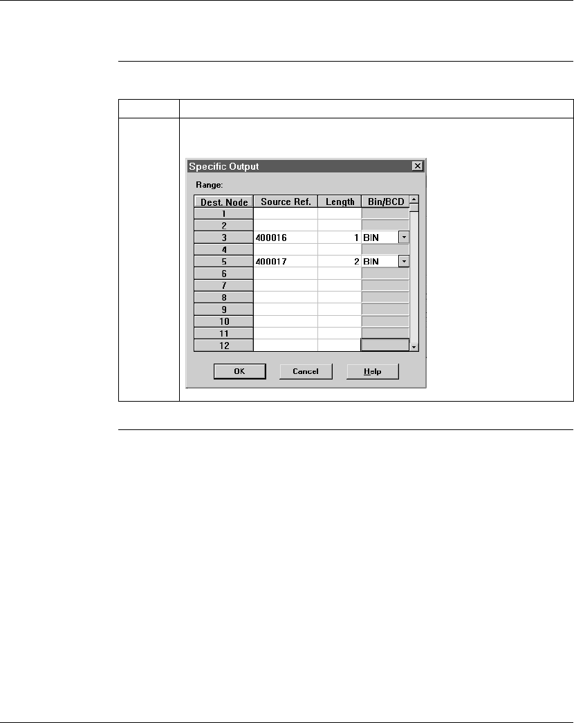
Configuring a Modbus Plus Network in Concept with Peer Cop
386 870 USE 101 10 V.2
Specifying References for Output Data, Continued
Procedure,
Continued Step Action
4 Repeat steps 2 and 3 for the device at address 5, using the settings in the
figure below. Then click <OK>.

Configuring a Modbus Plus Network in Concept with Peer Cop
870 USE 101 10 V.2 387
Section 14.3
Passing Supervisory Data over Modbus Plus
Overview
Purpose This Peer Cop example deals with a network where three CPUs communicate over
Modbus Plus. Each device will need to have its own Peer Cop configuration.
In This Section This section contains the following topics:
For This Topic... See Page...
Devices on the Network 388
Specifying References for Input and Output Data 389
Defining the References for the Next Node 393
Defining References for the Supervisory PLC 396

Configuring a Modbus Plus Network in Concept with Peer Cop
388 870 USE 101 10 V.2
Devices on the Network
Introduction This section describes the three CPUs which exchange data over the sample
Modbus Plus network and the strategy used to assign node addresses.
Devices The three CPUs and their functions are described in the following table:
Address
Strategy In this type of architecture, assign the lowest network address (1) to the
supervisory computer. When the network initializes, the supervisor will be the first
device to get the token, and the token rotation table will be built with respect to the
supervising device.
MB+ Address CPU Function
1 Pentium supervisory computer with an
ATRIUM 180-CCO-111-01 host-based
PLC card
Receives specific input data
and sends global outputs
2 171 CCS 760 00 Momentum M1
Processor Adapter with
172 PNN 210 22 Modbus Plus Option
Adapter
Controls I/OBus network
and exchanges data with
ATRIUM supervisor
3 171 CCS 760 00 Momentum M1
Processor Adapter with
172 PNN 210 22 Modbus Plus Option
Adapter
Controls I/OBus network
and exchanges data with
ATRIUM supervisor
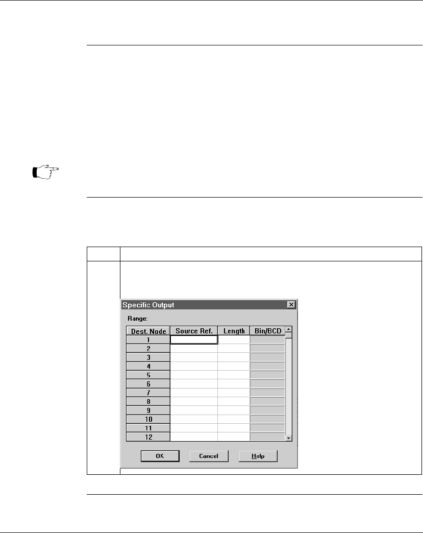
Configuring a Modbus Plus Network in Concept with Peer Cop
870 USE 101 10 V.2 389
Specifying References for Input and Output Data
Overview We will now set up the 171 CCS 760 00 Momentum M1 CPU at Modbus Plus
address 2 to:
l send eight 4
x
registers of specific output to the supervisory computer at
Modbus Plus address 1.
lreceive five 4
x
registers of global input data from the ATRIUM supervisor.
These registers are the first five registers in a 10-register block of global
outputs broadcast by the supervisory controller.
Defining the
Specific Output The following table describes how to define the specific output, starting from the
Peer Cop dialog box.
Continued on next page
Note: For this example, we will use the default values for Health Timeout (500
ms) and Last Value (Clear on timeout).
Step Action
1 Click on the Specific Output... button.
Result: The Specific Output dialog box appears.
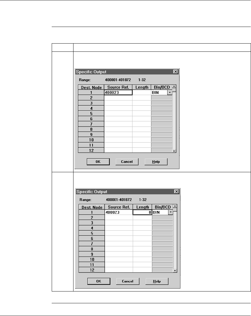
Configuring a Modbus Plus Network in Concept with Peer Cop
390 870 USE 101 10 V.2
Specifying References for Input and Output Data, Continued
Defining the
Specific Output,
Continued
Continued on next page
Step Action
2 Since you are addressing the device at address 1, you will use the line for Source
1. Type the value 400023 on that line in the Dest. Ref. column.
3 Type the value 8 in the Length column, indicating that 8 words of data will be
exchanged. In this case, we will leave the default BIN setting. Click <OK>.
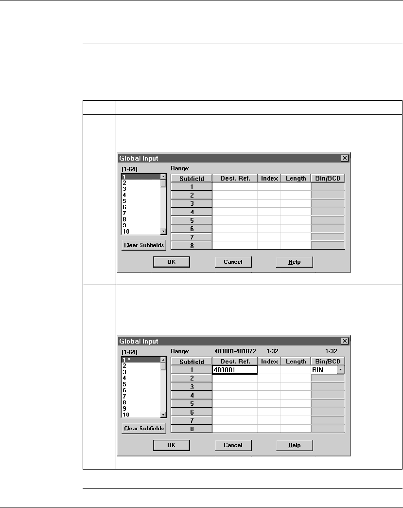
Configuring a Modbus Plus Network in Concept with Peer Cop
870 USE 101 10 V.2 391
Specifying References for Input and Output Data, Continued
Defining the
Global Inputs Now the M1 needs to be Peer Copped to receive five words of global data from the
supervisory PLC at Modbus Plus address 1. Follow the steps in the table specify
the input reference.
Continued on next page
Step Action
1 Click on the Global Input... button.
Result: The Global Input dialog box appears.
2 Since this device will be receiving data from the CPU at address 1, you do not
need to change the default sending address (selected under the heading 1-64).
Type 400001 in the Dest. Ref column on the first line, to indicate the first register
the CPU will use to store the input data.
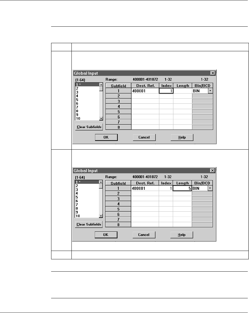
Configuring a Modbus Plus Network in Concept with Peer Cop
392 870 USE 101 10 V.2
Specifying References for Input and Output Data, Continued
Defining the
Global Inputs,
Continued
Next Step Defining the references for the next node.
Step Action
3 Type the value 1 in the Index column, indicating that the CPU will receive part of
the global input data beginning with the first word.
4 Type the value 5 in the Length column, indicating that the CPU will accept five
words of the global input data. Leave the default BIN setting.
5 Click <OK>.

Configuring a Modbus Plus Network in Concept with Peer Cop
870 USE 101 10 V.2 393
Defining the References for the Next Node
Overview We now want to attach the Concept 2.2 programming panel to the 171 CCS 760 00
Momentum M1 CPU at Modbus Plus address 3 and create a similar Peer Cop for
this device to communicate with the supervisory PLC at Modbus Plus address 1. In
this case, we want the M1:
lto send 16 words of specific output to the supervisor.
lto receive the last seven words of global input from the supervisor. (Remember
that the supervisor will be transmitting a total of 10 contiguous words of global
data over the network.)
Continued on next page
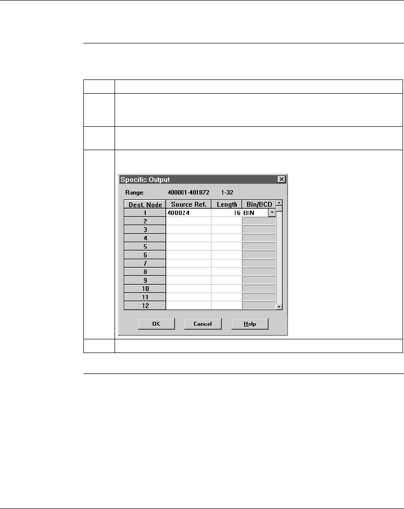
Configuring a Modbus Plus Network in Concept with Peer Cop
394 870 USE 101 10 V.2
Defining the References for the Next Node, Continued
Defining Specific
Outputs Follow the steps in the table below to define the specific output in Peer Cop.
Continued on next page
Step Action
1 Click on the Specific Output... button.
Result: The Specific Output dialog box appears.
2 Since you are addressing the device at address 1, you will use the line for Source
1. Type the value 400024 on that line in the Dest. Ref. column.
3 Type the value 16 in the Length column, indicating that 16 words of data will be
exchanged. In this case, we will leave the default BIN setting.
4 Click <OK>.
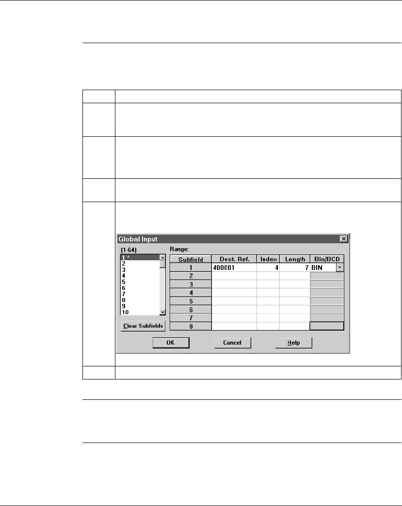
Configuring a Modbus Plus Network in Concept with Peer Cop
870 USE 101 10 V.2 395
Defining the References for the Next Node, Continued
Defining Global
Inputs Follow the steps in the table below to define the global input data from the
supervisory PLC at Modbus Plus address 1.
Next Step Defining references for the supervisory PLC.
Step Action
1 Click on the Global Input... button.
Result: The Global Input dialog box appears.
2 Since this device will be receiving data from the CPU at address 1, you do not
need to change the default sending address (selected under the heading 1-64).
Type 400001 in the Dest. Ref column on the first line, to indicate the first register
the CPU will use to store the input data.
3 Type the value 4 in the Index column, indicating that the CPU will receive part of
the global input data beginning with the fourth word.
4 Type the value 7 in the Length column, indicating that the CPU will accept seven
words of the global input data. Leave the default BIN setting.
5 Click <OK>.
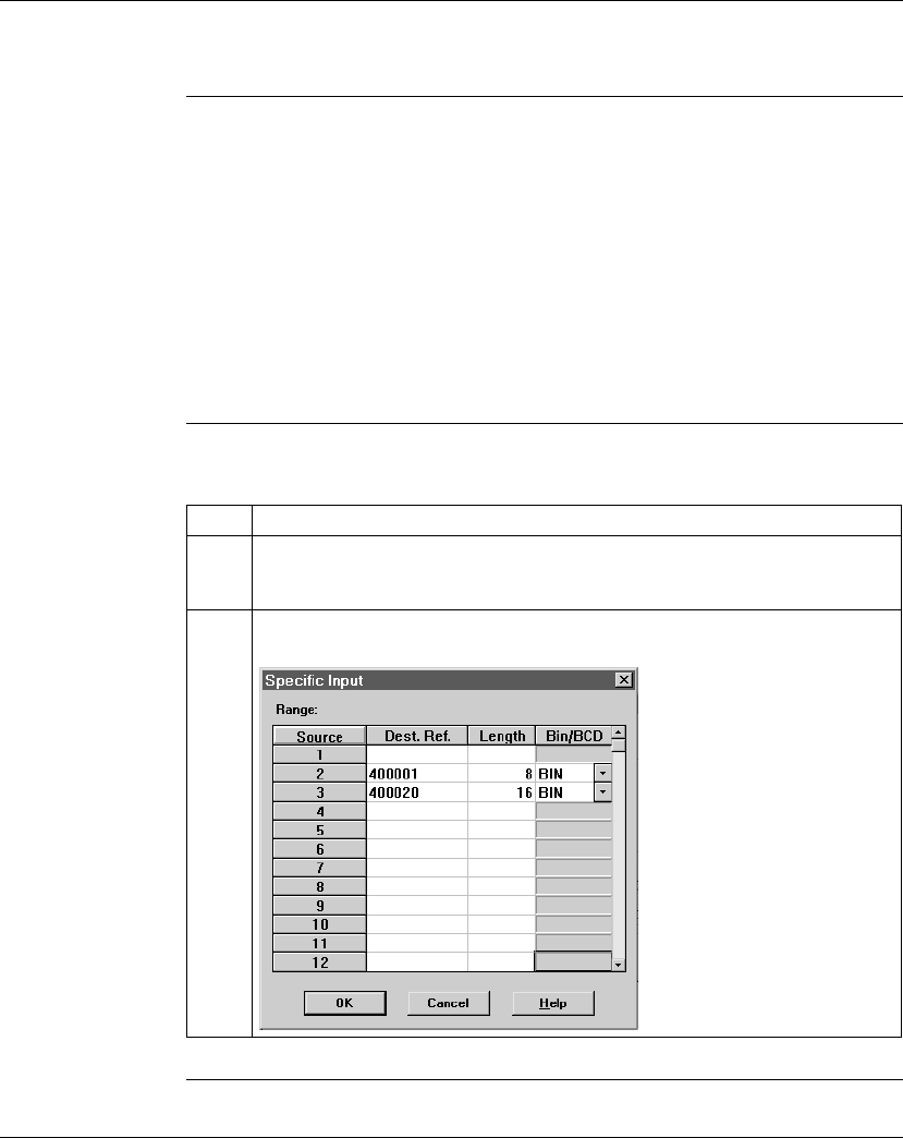
Configuring a Modbus Plus Network in Concept with Peer Cop
396 870 USE 101 10 V.2
Defining References for the Supervisory PLC
Overview At this point, we will attach the Concept 2.1 programming panel to the
ATRIUM 180-CCO-111-01 supervisory PLC at Modbus Plus address 1 and set up
Peer Cop screens to handle the M1 CPUs at addresses 2 and 3.
We know that the M1 at Modbus Plus address 2 is sending eight words of specific
output to the supervisor and that the M1 at Modbus Plus address 3 is sending 16
words of specific output to the supervisor. The supervisor will receive this data as
specific inputs.
We also know that the supervisor is sending 10 words of global data, parts of which
will be received by both of the M1 CPUs.
Defining the
Specific Inputs First we will define the specific inputs to be received by the supervisor.
Continued on next page
Step Action
1 Click on the Specific Input... button.
Result: The Specific Input dialog box appears.
2 Enter the references for each CPU on the appropriate source line, as shown below.
Then click <OK>.
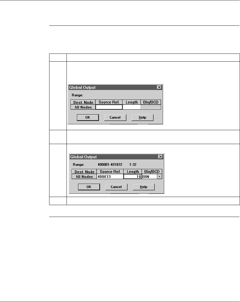
Configuring a Modbus Plus Network in Concept with Peer Cop
870 USE 101 10 V.2 397
Defining References for the Supervisory PLC, Continued
Defining the
Global Outputs This supervisory CPU sends out 10 words of global output, parts of which are
received by each of the M1 CPUs.
Step Action
1 Click on the Global Output... button.
Result: The Global Output dialog box appears.
2 In the Source Ref. column, type the value 400033, the first register which will be
sent.
3 In the Length column, type the value 10, the number of registers that will be sent.
4 Click <OK>.

Configuring a Modbus Plus Network in Concept with Peer Cop
398 870 USE 101 10 V.2

870 USE 101 10 V.2 399
Saving to Flash with Concept
Saving to Flash
Overview You save to Flash so that, in the event of an unexpected loss of power, the
application logic and state RAM values will be preserved.
This section describes how to save the application logic and state RAM values to Flash using Concept 2.1.
Note: You can save to Flash if you are using the 984LL executive for all models,
except 171 CCC 960 30 and the 171 CCC 980 30. You can only save to
Flash on the 171 CCC 960 30 and the 171 CCC 980 30 if you are using
the Concept IEC executive.
Note: The 171 CCC 960 30 and 171 CCC 980 30 require Concept 2.2 with
service release 2.
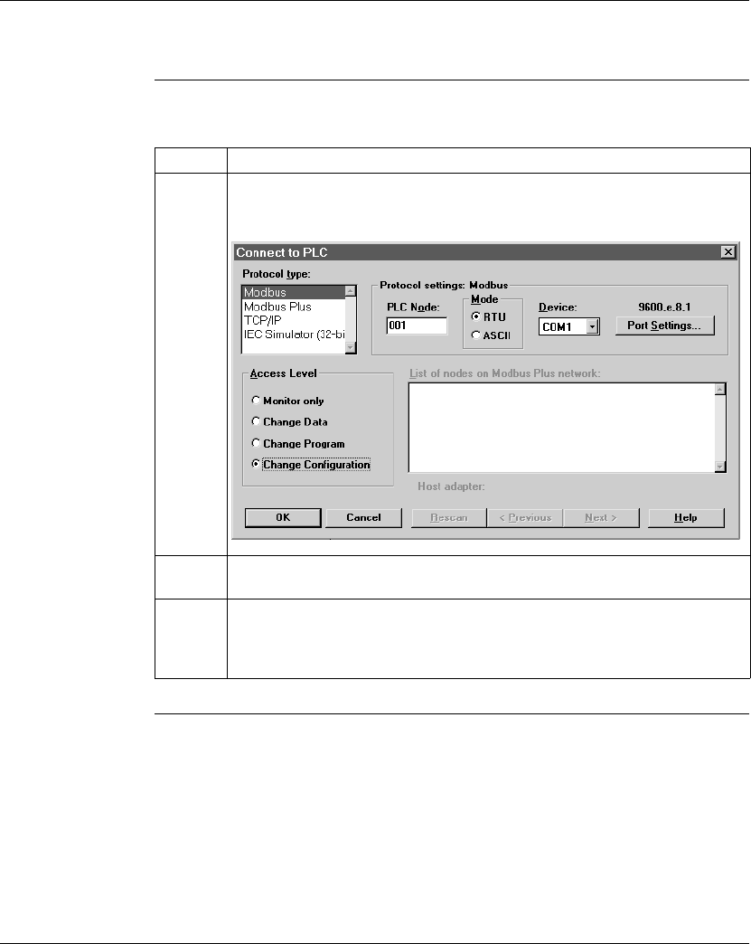
Saving to Flash with Concept
400 870 USE 101 10 V.2
Saving to Flash, Continued
Procedure Follow the steps in the table below to save to Flash:
Continued on next page
Step Action
1From the Online menu on the main menu bar, select Connect.
Result: The Connect to PLC dialog box appears.
2Select the correct parameters to connect with your PLC. Under Access Level,
select the radio button to Change Configuration.
3Click OK.
Result: The Connect to PLC dialog box disappears and Concept connects to
your PLC.
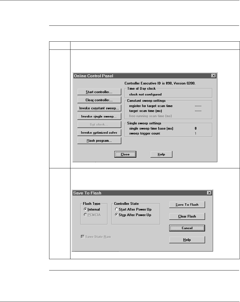
Saving to Flash with Concept
870 USE 101 10 V.2 401
Saving to Flash, Continued
Procedure,
Continued
Continued on next page
Step Action
4From the Online menu on the main menu bar, select Online control panel.
Result: The Online Control Panel appears.
5Click the Flash program... button.
Result: The Save to Flash dialog box appears.

Saving to Flash with Concept
402 870 USE 101 10 V.2
Saving to Flash, Continued
Procedure,
Continued Step Action
6Select the appropriate parameters in the dialog box and click the Save to Flash
button.
Result: A dialog box will appear asking if you really want to save to Flash.
Note: When you press the Yes (for Save to Flash) button, the
previous applications will be overwritten.
7Click the Yes button.
Result: Concept completes the save to Flash and a message appears on the
screen confirming the completed save.

870 USE 101 10 V.2 403
Appendices
At a Glance
Purpose This part provides supplemental information on Ladder Logic elements and
instructions and LED flash patterns and error codes.
In This Part This part contains the following chapters:
For Information On ... See Appendix... See Page...
Ladder Logic Elements and Instructions A 405
Run LED Flash Patterns and Error Codes B 417

870 USE 101 10 V.2 405
Ladder Logic Elements and
Instructions
At a Glance
Overview The executive firmware for the Momentum M1 Processor Adapters supports the
ladder logic programming language for control applications. The following core set
of ladder logic elements (contacts, coils, vertical and horizontal shorts) and
instructions are built into the CPU’s firmware package. For a detailed description of
all instructions, see the
Ladder Logic Block Library User Guide
(840 USE 101 00).
In This Appendix This appendix contains the following topics:
For This Topic... See Page...
Standard Ladder Logic Elements 406
DX Loadable Support 410
A Special STAT Instruction 411

Ladder Logic Elements and Instructions
406 870 USE 101 10 V.2
Standard Ladder Logic Elements
Introduction This section provides a glossary of standard ladder logic symbols and instructions.
Ladder Logic
Symbols The table below provides the meaning of standard ladder logic symbols.
Continued on next page
Symbol Meaning Nodes Consumed
Normally open (N.O.) contact 1
Normally closed (N.C.) contact 1
Positive transitional (P.T.) contact 1
Negative transitional (N.T.) contact 1
Normal coil 1
Memory-retentive or latched coil; the
two symbols mean the same thing, and
the user may select the preferred
version for online display.
1
Horizontal short 1
Vertical short 0

Ladder Logic Elements and Instructions
870 USE 101 10 V.2 407
Standard Ladder Logic Elements, Continued
Standard Ladder
Logic
Instructions
The table below provides standard ladder logic instructions and their meaning.
Continued on next page
Symbol Meaning Nodes Consumed
Counter and Timer Instructions
UCTR Counts up from 0 to a preset value 2
DCTR Counts down from a preset value to 0 2
T1.0 Timer that increments in seconds 2
T0.1 Timer that increments in tenths of a second 2
T.01 Timer that increments in hundredths of a second 2
T1MS A timer that increments in milliseconds 3
Integer Math Instructions
ADD Adds top node value to middle node value 3
SUB Subtracts middle node value from top node value 3
MUL Multiplies top node value by middle node value 3
DIV Divides top node value by middle node value 3
DX Move Instructions
R∀T Moves register values to a table 3
T∀R Moves specified table values to a register 3
T∀T Moves a specified set of values from one table to
another table
3
BLKM Moves a specified block of data 3
FIN Specifies first-entry in a FIFO queue 3
FOUT Specifies first-entry out of a FIFO queue 3
SRCH Performs a table search 3
STAT CROSS REF 1

Ladder Logic Elements and Instructions
408 870 USE 101 10 V.2
Standard Ladder Logic Elements, Continued
Standard Ladder
Logic
Instructions,
Continued
Continued on next page
Symbol Meaning Nodes Consumed
DX Matrix Instructions
AND Logically ANDs two matrices 3
OR Does logical inclusive OR of two matrices 3
XOR Does logical exclusive OR of two matrices 3
COMP Performs logical complement of values in a matrix 3
CMPR Logically compares values in two matrices 3
MBIT Logical bit modify 3
SENS Logical bit sense 3
BROT Logical bit rotate 3
AD16 Signed/unsigned 16-bit addition 3
SU16 Signed/unsigned 16-bit subtraction 3
TEST Compares the magnitudes of the values in the top and
middle nodes
3
MU16 Signed/unsigned 16-bit multiplication 3
DV16 Signed/unsigned 16-bit division 3
ITOF Signed/unsigned integer-to-floating point conversion 3
FTOI Floating point-to-signed/unsigned integer conversion 3
EMTH Performs 38 math operations, including floating point
math operations and extra integer math operations
such as square root
3
Ladder Logic Subroutine Instructions
JSR Jumps from scheduled logic scan to a ladder logic
subroutine
2
LAB Labels the entry point of a ladder logic subroutine 1
RET Returns from the subroutine to scheduled logic 1

Ladder Logic Elements and Instructions
870 USE 101 10 V.2 409
Standard Ladder Logic Elements, Continued
Standard Ladder
Logic
Instructions,
Continued
Symbol Meaning Nodes Consumed
Other Special Purpose Instructions
CKSM Calculates any of four types of checksum
operations (CRC-16, LRC, straight CKSM,
and binary add)
3
MSTR Specifies a function from a menu of
networking operations
3
PID2 Performs proportional-integral-derivative
calculations for closed-loop control
3
TBLK Moves a block of data from a table to
another specified block area
3
BLKT Moves a block of registers to specified
locations in a table
3
XMIT Allows CPU to act as a Modbus master 3

Ladder Logic Elements and Instructions
410 870 USE 101 10 V.2
DX Loadable Support
Introduction The M1 CPUs can use DX loadable instructions, which support optional software
products that can be purchased for special applications. DX loadables provide the
user with special ladder logic functions.
Loaded on
Page 0 The code for DX loadables gets loaded into the Page 0 area. Thus, for every word
of DX loadable that is loaded, one word of Page 0 becomes unavailable for other
use (such as application logic).
Limited
Functionality DX loadables are limited in the functionality they can provide because they do not
provide storage for variables and are limited in their size.
M1 Support M1 supports only loadables targeted for 80x86 microprocessors running in 16-bit
real mode that have not made any hard-coded hardware assumptions (e.g., the
address and format of the TOD clock). Obviously, there must be enough available
memory to fit the loadable.
Saved to Flash Since DX loadables are stored in Page 0 memory, they are saved whenever a
save-to-Flash operation is initiated.

Ladder Logic Elements and Instructions
870 USE 101 10 V.2 411
A Special STAT Instruction
Overview A special version of the STAT instruction has been developed to support
Momentum M1 CPUs. The STAT instruction accesses a specified number of words
in a status table in the CPU’s system memory. Here vital diagnostic information
regarding the health of the CPU and the I/OBus I/O under its control is posted.
From the STAT instruction, you can copy some or all of the status words into a
block of registers or a block of contiguous discrete references.
This section describes the STAT instruction.
Avoid Discretes We recommend that you do not use discretes in the STAT destination node
because of the excessive number required to contain status information.
Specify Length The copy to the STAT block always begins with the first word in the table up to the
last word of interest to you. For example, if the status table is 20 words long and
you are interested only in the statistics provided in word 11, you need to copy only
words 1...11 by specifying a
length
of 11 in the STAT instruction.
Diagram of STAT
Block The STAT block includes a top node (for destination) and a bottom node (for
length). The STAT block is represented in the following illustration.
Continued on next page

Ladder Logic Elements and Instructions
412 870 USE 101 10 V.2
A Special STAT Instruction, Continued
Top Node
Content The reference number entered in the top node is the first position in the destination
block–i.e., the block where the current words of interest from the status table will be
copied. The reference may be:
lThe first 0x reference in a block of contiguous discrete outputs
lThe first 4x reference in a block of contiguous holding registers
Bottom Node
Content The integer value entered in the bottom node specifies the number of registers or
16-bit words in the destination block where the current status information will be
written.
The length–i.e., number of words–in the status table will vary depending on
whether or not I/OBus I/O is being supported:
lWithout I/OBus, the STAT instruction is 12 words long.
lWith I/OBus, the instruction is 20 words long.
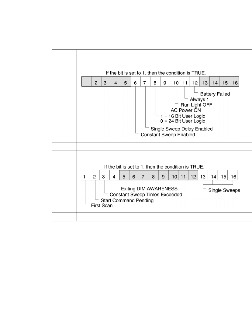
Ladder Logic Elements and Instructions
870 USE 101 10 V.2 413
A Special STAT Instruction, Continued
Words 1...12 The first 12 words describe the CPU status and are detailed in the following table:
Continued on next page
Word Description
1 Displays the following aspects of the PLC’s status:
2 Reserved for internal use.
3 Displays more aspects of the controller status:
4Not used.
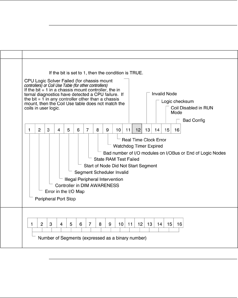
Ladder Logic Elements and Instructions
414 870 USE 101 10 V.2
A Special STAT Instruction, Continued
Words 1...12,
Continued
Continued on next page
Word Description
5 Displays the PLC’s stop state conditions:
6 Displays the number of segments in ladder logic; a binary number is shown:
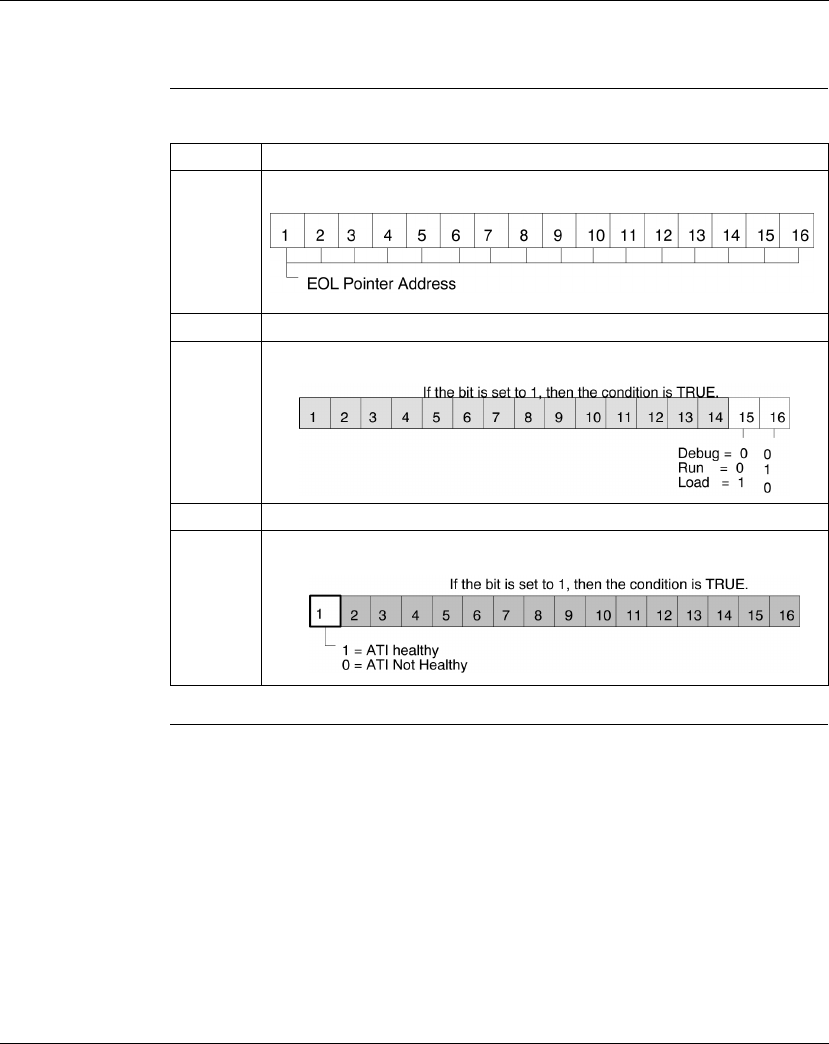
Ladder Logic Elements and Instructions
870 USE 101 10 V.2 415
A Special STAT Instruction, Continued
Words 1...12,
Continued
Continued on next page
Word Description
7 Displays the address of the end-of-logic (EOL) pointer:
8 and 9 Not used.
10 Uses its two least significant bits to display RUN/LOAD/DEBUG status:
11 Not used.
12 Indicates the health of the ATI module:

Ladder Logic Elements and Instructions
416 870 USE 101 10 V.2
A Special STAT Instruction, Continued
Words 13...20 Words 13...20 are available only for the 171 CCS 760 00 and 171 CCS 760 10
Momentum M1 Processor Adapters to indicate the status of I/OBus modules
controlled over the I/O Bus network.
This Word... Indicates the Status of These I/O Modules...
13 1...16
14 17...32
15 33...48
16 49...64
17 65...80
18 81...96
19 97...112
20 113...128

870 USE 101 10 V.2 417
Run LED Flash Patterns and Error
Codes
Run L7ED Flash
Pattern and Error
Codes
The following table lists the flash pattern of the Run LED on the Momentum
Processor Adapters. It also lists the associated codes (in hex format).
Continued on next page
Number of Blinks Code (hex) Error
Continuous 0000 Requested Kernel mode
2080B ram error during sizing
080C run output active failed
082E MB command handler stack error
0835 Main loop broken
0836 Power down / Power holdup
0837 Power down reset absent
3072B master config write bad

Run LED Flash Patterns and Error Codes
418 870 USE 101 10 V.2
Run LED Flash
Pattern and Error
Codes, Continued
Continued on next page
Number of Blinks Code (hex) Error
40607 modbus cmd-buffer overflow
0608 modbus cmd-length is zero
0609 modbus abort command error
0614 mbp bus interface error
0615 bad mbp response opcode
0616 timeout waiting for mbp
0617 mbp out of synchronization
0618 mbp invalid path
0619 page 0 not paragraph aligned
061E bad external uart hardware
061F bad external uart interrupt
0620 bad receive comm state
0621 bad transmit comm state
0622 bad comm state trn_asc
0623 bad comm state trn_rtu
0624 bad comm state rcv_rtu
0625 bad comm state rcv_asc
0626 bad modbus state tmr0_evt
0627 bad modbus state trn-int
0628 bad modbus state rcv-int
0631 bad interrupt
0637 Bad I/OBus transmit state
0638 Bad I/OBus receive state
50503 ram address test error
052D P.O.S.T BAD MPU ERROR
60402 ram data test error

Run LED Flash Patterns and Error Codes
870 USE 101 10 V.2 419
Run LED Flash
Pattern and Error
Codes, Continued Number of Blinks Code (hex) Error
70300 EXEC not loaded
0301 EXEC Checksum
88001 Kernal prom checksum error
8003 unexpected exec return
8005 Flash program / erase error
8007 Watchdog timeout event

Run LED Flash Patterns and Error Codes
420 870 USE 101 10 V.2

870 USE 101 10 V.2 421
Numerics
171 CCC 760 10 Processor Adapter
diagram, 38
key features, 38
LEDs, 39
specifications, 39
171 CCC 780 10 Processor Adapter
changing protocol to RS485, 241
diagram, 44
key features, 44
LEDs, 45
need to change protocol to RS485, 122
specifications, 45
171 CCS 700 00 Processor Adapter
diagram, 29
key features, 29
LEDs, 30
specifications, 30
171 CCS 700 10 Processor Adapter
diagram, 32
key features, 32
LEDs, 33
specifications, 33
171 CCS 760 00 Processor Adapter
diagram, 35
key features, 35
LEDs, 36
specifications, 36
171 CCS 780 00 Processor Adapter
changing protocol to RS485, 241
diagram, 41
key features, 41
LEDs, 42
need to change protocol to RS485, 122
specifications, 42
172 JNN 210 32 Serial Option Adapter
diagram, 68
LED indicator, 69
limitations when used with certain
processor adapters, 120
specifications, 71
172 PNN 210 22 Modbus Plus Option
Adapter
diagram, 74
LED indicator, 75
Modbus Plus address switches, 76
specifications, 77
172 PNN 260 22 Redundant Modbus Plus
Option Adapter
diagram, 80
LED indicators, 81
Modbus Plus address switches, 83
ports, 83
specifications, 84
A
Assembly
Processor Adapter and I/O base, 89
Processor Adapter and Option Adapter,
Index

Index
422 870 USE 101 10 V.2
95
Processor Adapter, Option Adapter and
I/O base, 98
C
communication ports
configuring with Concept, 336
configuring with Modsoft, 232
delay parameter, 240, 341
stop bit, 234, 340
CPU Configuration Page, 166
links, 166
E
Ethernet tester
Requirements, 158
I
I/OBus network
accessing an I/O map screen, 250
editing an I/O map, 252, 365
supporting an I/O map, 248, 249, 362
I/OBus port, 23, 172
InterBus module identifier codes, 255, 366
L
Ladder logic, 405
local I/O
I/O mapping with Concept, 357
I/O mapping with Modsoft, 242
M
M1E I/O Status Page, 165, 167
links, 167
Modbus Plus
addresses, 198
cluster mode, 182
cabling schemes, 187
network types, 183
new features for Momentum, 182
Peer Cop, 200
standard cabling schemes, 185
Modbus Plus network architecture
address strategy, 264, 282, 377, 388
two types, 257, 369
Modbus Plus port, 181
cable accessories, 191
pinouts and wiring diagrams, 194
Modbus Port 1, 22, 113
auto-logout feature, 115
cable accessories, 116
connector type, 113
diagram, 113
parameters, 114
Modbus Port 2, 23, 69, 120
auto-logout, 69
autologout feature with RS232, 122
changing protocol from RS232 to
RS485, 241, 343
parameters, 121
pinouts, 70
Modbus RS485, 120
cable, 129
connectors, 132
four-wire cabling schemes, 123
pinouts, 135
terminating devices, 134
two-wire cabling schemes, 126
Momentum M1E Web Pages, 165
Momentum M1E Welcome Page, 165
links, 165
N
Network design considerations, 144
NOE 771 x0
Embedded web server, 162
O
Option Adapter
batteries
installation, 105

Index
870 USE 101 10 V.2 423
purpose, 66
reserving and monitoring a battery
coil in Concept, 328
reserving and monitoring a battery
coil in Modsoft, 224
communication ports, 66
configuring in Concept, 327
configuring in Modsoft, 223
purpose, 65
time-of-day clock, 66
reading in Concept, 335
reading in Modsoft, 231
setting the time in Modsoft, 228
setting time in Concept, 334
setting up in Concept, 331
setting up in Modsoft, 226
P
Peer Cop, 200
Concept
accessing Peer Cop dialog box, 371
health timeout, 374
Last Value setting, 375
specifying references for input data,
380
specifying references for output
data, 384
Modsoft
accessing a node, 265
accessing configuration extension
screen, 259
adjusting amount of extension
memory, 259
defining a link, 265
On Error setting, 268
specifying references for input data,
272
timeout, 268
Processor Adapter
configuring with Concept, 310
configuring with Modsoft, 207
default configuration parameters in
Concept, 315
default configuration parameters in
Modsoft, 212
Flash RAM, 24
front panel diagram, 21
internal memory, 24
power supply, 27
R
Run LED Flash Patterns and Error Codes,
417
S
saving to Flash
Concept
procedure, 400
Modsoft
options, 304
procedure, 305
purpose, 303, 399
Stop bit, 122
Supervisory network, 145
Support Page, 169
links, 170
W
Web server
Accessing the home page, 163
Embedded web pages, 162
Features, 163
Internet Explorer, 163
Netscape Navigator, 163

Index
424 870 USE 101 10 V.2
Modicon, Square D and Telemecanique are PLC brand names from Schneider. These products are sold in
the US by Square D; in Canada, Latin America, Europe, Africa, Asia/Pacific and Middle East by Schneider; in
Germany by AEG Schneider Electric; in China and Persian Gulf by Schneider Electric; in South Africa by
ASA Systems Automation; in Austria by Online.
Schneider Electric, Inc. Schneider Electric GmbH Schneider Electric S.A.
One High Street Steinheimer Strasse 117 245, Route des Lucioles-BP147
North Andover, MA 01845 D-63500 Seligenstadt F-06903 Sophia-Antipolis Cedex
Tel: (1) 508-794-0800 Tel: (49) 6182 81-2584 Tel: (33) 92 96 20 00
Fax: (1) 508-975-9400 Fax: (49) 6182 81-2860 Fax: (33) 93 65 37 15
870 USE 101 10 V.2 © 2000 Schneider Electric, Inc. All rights reserved
4/00
.
31002674
