Schulmerich Carillons 0362018010 Outdoor Carillon Radio Remote Control User Manual SCHEMATIC1 PAGE1
Schulmerich Carillons, Inc. Outdoor Carillon Radio Remote Control SCHEMATIC1 PAGE1
Contents
- 1. Installation Instructions
- 2. Revised Manual
Installation Instructions
5
5
4
4
3
3
2
2
1
1
D D
C C
B B
A A
Title
Size Document Number Rev
Date: Sheet of
042-1202-000 C
Gen4 Outdoor Radio Remote WD
SCHULMERICH CARILLONS, INC
ONE CARILLON HILL
SELLERSVILLE, PA 18960
B
11Wednesday, March 24, 2004
Title
Size Document Number Rev
Date: Sheet of
042-1202-000 C
Gen4 Outdoor Radio Remote WD
SCHULMERICH CARILLONS, INC
ONE CARILLON HILL
SELLERSVILLE, PA 18960
B
11Wednesday, March 24, 2004
Title
Size Document Number Rev
Date: Sheet of
042-1202-000 C
Gen4 Outdoor Radio Remote WD
SCHULMERICH CARILLONS, INC
ONE CARILLON HILL
SELLERSVILLE, PA 18960
B
11Wednesday, March 24, 2004
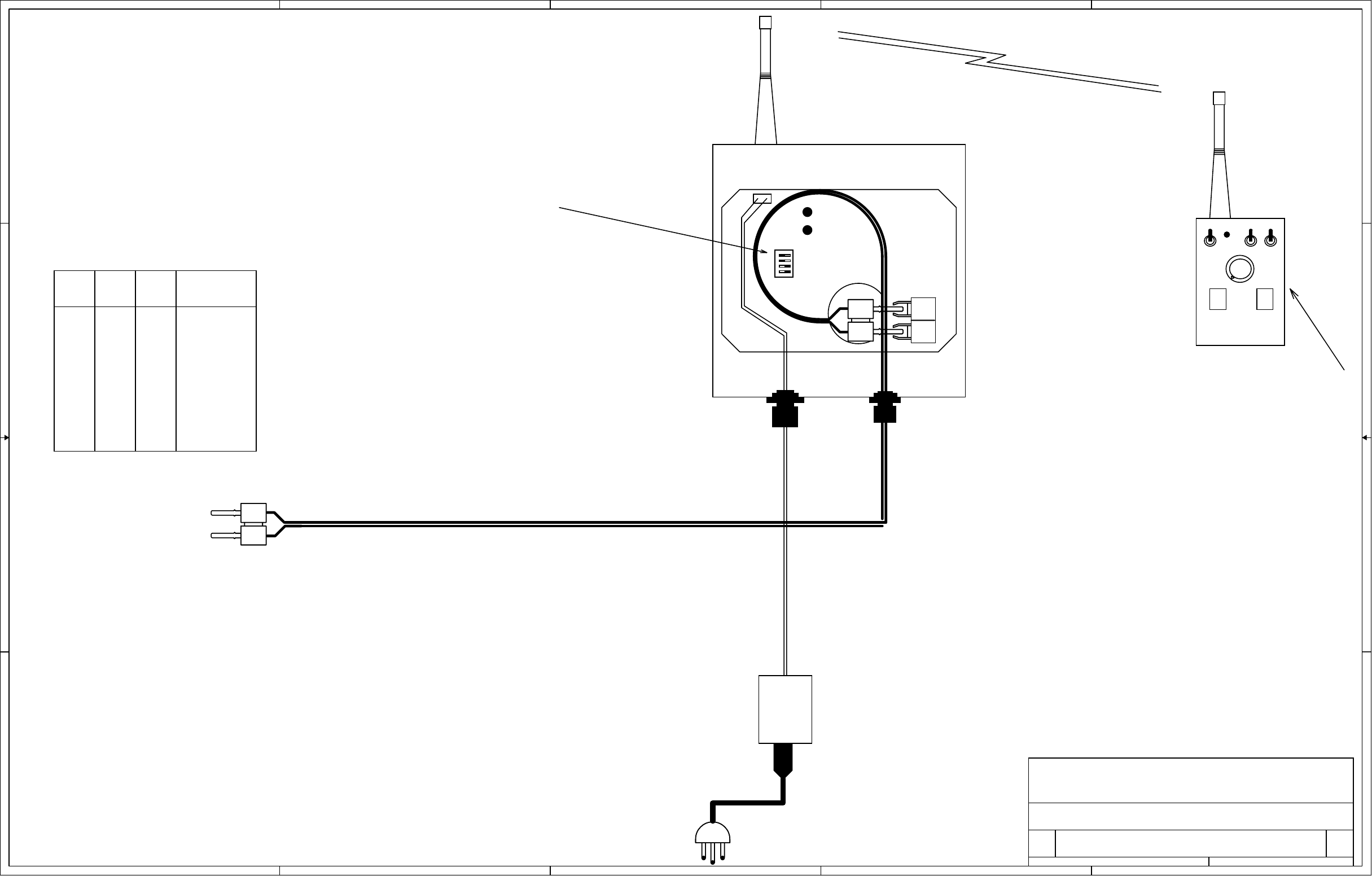
RECEIVER
(036-2017-010)
AC POWER PACK
(006-1136-000)
DUAL FIBER OPTIC CABLE (012-0738-010)
100 FT. STANDARD
350 FT. MAXIMUM WITHOUT EXPANDER Power pack DC output cable is coaxial.
The shield is the negative lead.
12VDC
Dedicated receptacle not
required for power pack.
Hand-Held
Battery-Powered
TRANSMITTER
(036-2016-010)
+
-
1
903.37 to 921.37 MHz
T
R
DIP Switch Settings:
Switches 1 thru 4
must match the
receiver.
DIP Switch Settings:
ON ON ON 903.37
OFF ON ON 906.37
ON OFF ON 907.87
OFF OFF ON 909.37
ON ON OFF 912.37
OFF ON OFF 915.37
ON OFF OFF 919.87
OFF OFF OFF 921.37
1 2 3 MHz
DipSwitch Chart
Top Assembly: 036-2018-010
Operating Manual: 046-1210-000
Switches 1 thru 4 select among sixteen different ID codes.
Switches 1 thru 3 select among eight different frequencies.
Switch 3 ON means the inside speaker switch works.
Switch 4 ON means the tower speaker switch works.
Receiver may be mounted directly to the side of a building.
Flanges may be drilled to mount on a mast clamp, etc.
If box is drilled, it must be sealed with UV resistant sealant.
Antenna should be vertical and in the line-of sight with the
customer's intended transmitting location(s).
Receiver should be as far as possible (min 15ft) from all sources
of electromagnetic interference and as high as practical.
Indoor or other unusual locations may be tested by observing
the brightness of the signal strength LED.
RUN/STATUS
SIGNAL STRENGTH
Installation Instructions for Gen4
Outdoor Radio Remote Control
120 VAC120 VAC