Schweitzer Engineering Laboratories SEL-8310 SEL-8310 User Manual Ranger IM
Schweitzer Engineering Laboratories, Inc. SEL-8310 Ranger IM
User Manual

RADIORANGER
Wireless Fault
Indication System
Instruction Manual
*PM8300-01*
20070301
© 2007 by E.O. Schweitzer Manufacturing, a Division of SEL. All rights reserved.
All trademarks are the property of their respective holders. E.O. Schweitzer Manufacturing products appearing
in this document may be covered by US and Foreign patents.
The information in this document is provided for informational use only and is subject to change without notice.
Equipment components are sensitive to
electrostatic discharge (ESD). Undetectable
permanent damage can result if you do not
use proper ESD procedures. Ground yourself,
your work surface, and this equipment
before removing any cover from this
equipment. If your facility is not equipped to
work with these components, contact SEL
about returning this device and related SEL
equipment for service.
!
CAUTION
Disconnect or de-energize all external
connections before opening this device.
Contact with hazardous voltages and
currents inside this device can cause
electrical shock resulting in injury or death.
!
DANGER
Les composants de cet équipement sont
sensibles aux décharges électrostatiques
(DES). Des dommages permanents non-
décelables peuvent résulter de l’absence de
précautions contre les DES. Raccordez-vous
correctement à la terre, ainsi que la surface
de travail et l’appareil avant d’en retirer un
panneau. Si vous n’êtes pas équipés pour
travailler avec ce type de composants,
contacter SEL afin de retourner l’appareil
pour un service en usine.
!
ATTENTION
Débrancher tous les raccordements externes
avant d’ouvrir cet appareil. Tout contact
avec des tensions ou courants internes à
l’appareil peut causer un choc électrique
pouvant entraîner des blessures ou la mort.
!
DANGER

Date Code 20070301 RADIORANGER Instruction Manual
Table of Contents
List of Tables........................................................................................................... iii
List of Figures...........................................................................................................v
Preface ..................................................................................................................... vii
Section 1: Introduction and Specifications
Introduction ............................................................................................................1.1
Product Overview...................................................................................................1.1
Connections and System Diagram .........................................................................1.2
Accessories.............................................................................................................1.2
General Safety Information....................................................................................1.3
Specifications .........................................................................................................1.4
Section 2: SEL-8300 Wireless Interface Installation
Introduction ............................................................................................................2.1
SEL-8300 Installation ............................................................................................2.2
SEL FCI Connections ............................................................................................2.4
Testing and Verifying Installation ..........................................................................2.5
Section 3: SEL-8310 Remote Fault Reader Operation
Introduction ............................................................................................................3.1
Power Requirements ..............................................................................................3.2
DIP Switch Settings ...............................................................................................3.2
Audio Indication.....................................................................................................3.4
Operation................................................................................................................3.9
Section 4: Testing and Troubleshooting
Introduction ............................................................................................................4.1
Self-Tests................................................................................................................4.1
Troubleshooting the SEL-8300 ..............................................................................4.1
Troubleshooting the SEL-8310 ..............................................................................4.2
Factory Assistance..................................................................................................4.3
Appendix A: Firmware and Manual Versions
Firmware ...............................................................................................................A.1
Instruction Manual ................................................................................................A.2
This page intentionally left blank

Date Code 20070301 RADIORANGER Instruction Manual
List of Tables
Table 3.1 Four Audio Modes Selectable With the DIP Switch Block...3.3
Table 3.2 DIP Switch Settings...............................................................3.3
Table 3.3 Duration of Audio Indications in Morse Code Mode............3.7
Table 3.4 Duration of Audio Indications in Row/Column Mode ..........3.7
Table 3.5 Complete List of SEL-8310 Audio Indications.....................3.8
Table 3.6 Remote Fault Reader LED Indication Description..............3.12
Table 4.1 Troubleshooting the SEL-8300..............................................4.1
Table 4.2 Troubleshooting the SEL-8310..............................................4.2
Table A.1 Firmware Revision History...................................................A.1
Table A.2 Instruction Manual Revision History....................................A.2
This page intentionally left blank

Date Code 20070301 RADIORANGER Instruction Manual
List of Figures
Figure 1.1 RADIORANGER System...................................................................1.2
Figure 2.1 SEL-8300 Wireless Interface............................................................2.1
Figure 2.2 SEL-8300 Dimensional Diagram......................................................2.2
Figure 2.3 SEL-8300 Installed in Underground Vault .......................................2.3
Figure 2.4 SEL-8300 Informational Diagram ....................................................2.4
Figure 2.5 The Wireless Interface Has 12 Magnetic Probe Ports ......................2.5
Figure 3.1 SEL-8310 Remote Fault Reader Front View ....................................3.1
Figure 3.2 Power-Up Audio Indication in All Audio Modes.............................3.4
Figure 3.3 POST Fail Audio Indication in All Audio Modes ............................3.4
Figure 3.4 Scan Initiate Audio Indication in All Audio Modes.........................3.5
Figure 3.5 Scan Complete Audio Indication in All Audio Modes.....................3.5
Figure 3.6 Response Received Audio Indication in All Audio Modes ..............3.5
Figure 3.7 FCI Status Summary–Tripped FCI(s) Indication in Silent Mode.....3.5
Figure 3.8 FCI Status Summary–Tripped FCI(s)
Indication in Summary, Row/Column, or Morse Code Mode.....3.5
Figure 3.9 FCI Status Summary–No
Tripped FCI(s) Indication in Silent Mode ...................................3.6
Figure 3.10 FCI Status Summary–No Tripped FCI(s)
Indication in Summary, Row/Column, or Morse Code Mode.....3.6
Figure 3.11 Data Collision Audio Indication in All Audio Modes......................3.6
Figure 3.12 Morse Code Audio Mode Dot-Dash Patterns ...................................3.7
Figure 3.13 Row/Column Audio Mode Dot-Dash Patterns .................................3.7
Figure 3.14 Button Press Audio Indication in all Modes.....................................3.8
Figure 3.15 Correct and Incorrect Positioning of the Remote Fault Reader......3.10
Figure 3.16 Wireless Interface ID LED Color Descriptions ..............................3.12
This page intentionally left blank

Date Code 20070301 RADIORANGER Instruction Manual
Preface
Manual Overview
The RADIORANGER™ Instruction Manual describes how to install, operate, and
troubleshoot the RADIORANGER Wireless Fault Indication System.
An overview of each manual section and topics follows:
Preface. Describes the manual organization and conventions used to present
information.
Section 1: Introduction and Specifications. Introduces the RADIORANGER
system and lists specifications.
Section 2: SEL-8300 Wireless Interface Installation. Describes how to install,
power, set, and test the underground Wireless Interface.
Section 3: SEL-8310 Remote Fault Reader Operation. Describes how to turn on,
operate, and adjust the Remote Fault Reader. Descriptions and tables
explain the various LED and audible indications.
Section 4: Testing and Troubleshooting. Describes how to test and troubleshoot
products in the field.
Appendix A: Firmware and Manual Versions. Lists firmware and manual revision
dates and a description of the modifications.
Page Numbering
This manual shows page identifiers at the top of each page; see the figure
below.
Page Number Format
Introduction & Specifications
Title Block Page Number
Product Overview
1.3

RADIORANGER Instruction Manual Date Code 20070301
Preface
Manual Overview
viii
The page number appears at the outside edge of each page; a vertical bar separates the
page number from the page title block. The page numbers of the RADIORANGER
Instruction Manual are represented by the following building blocks:
➤Section number
➤Actual page number in the particular section
The section title is at the top of the page title block, with the main subsection reference
in bold type underneath the section title.
Cross-References
Cross-references are formatted as described below in both the hard copy and electronic
documentation for the RADIORANGER. In the electronic documentation, clicking with
the mouse on cross-references takes you to the referenced location.
➤References to figures, tables, examples, and equations include only
the referenced item:
➢Table 3.1 (3 indicates the section number)
➢Figure 4.5 (4 indicates the section number)
➤References to headings on another page include the heading title and
the page number:
➢Disconnect Monitoring on page 3.8
Examples
This instruction manual uses several example illustrations and instructions to explain
how to effectively operate the RADIORANGER. These examples are for demonstration
purposes only; the firmware identification information or settings values included in
these examples may not necessarily match those in the current version of your
RADIORANGER.
Safety Information
This manual uses hazard statements, formatted and defined as follows:
!
CAUTION
Indicates a potentially hazardous situation that, if not avoided, may result in
minor or moderate injury or equipment damage.
!
WARNING
Indicates a potentially hazardous situation that, if not avoided, could result in
death or serious injury.
!
DANGER
Indicates an imminently hazardous situation that, if not avoided, will result in
death or serious injury.

Date Code 20070301 RADIORANGER Instruction Manual
Section 1
Introduction and Specifications
Introduction
Locating faults in complex underground distribution systems has always proven
challenging for electrical utilities. Troubleshooting often requires the time consuming
and dangerous tasks of blocking traffic, opening, ventilating, draining, and accessing
subsurface vaults in search of the fault location. SEL’s RADIORANGER™ Wireless
Fault Indication System allows utility personnel to have street-level access to the status
of faulted circuit indicators (FCIs) installed below grade. This system dramatically
reduces the need to access vaults during a patrol, which reduces fault-locating time and
improves personnel safety.
This section covers the following areas:
➤Product Overview
➤Connections and System Diagram
➤Accessories
➤General Safety Information
➤Specifications
Product Overview
The RADIORANGER is a wireless fault indication system for locating underground
faults at street level, mitigating the need to access subsurface enclosures to retrieve FCI
status. The RADIORANGER system consists of the SEL-8300 Wireless Interface (a
subsurface radio), the SEL-8310 Remote Fault Reader (a handheld device), and SEL
FCIs that connect to the Wireless Interface to convey FCI status, see Figure 1.1.
A variety of SEL FCIs can be ordered with a magnetic probe output in place of a visual
display. The magnetic probe output connects to keyed ports on the SEL-8300 Wireless
Interface. The SEL-8300 accepts up to 12 FCI magnetic probes, allowing a user to
monitor up to four 3-phase circuits per installation. The SEL-8300 communicates via
the unlicensed 900 MHz band to a handheld SEL-8310 Remote Fault Reader using a
proprietary protocol. The design of the protocol makes communicating with or
interfering with other devices unlikely. Utility personnel use the SEL-8310 to
interrogate multiple Wireless Interface units to determine the status of FCIs installed in
RADIORANGER Instruction Manual Date Code 20070301
Introduction and Specifications
Connections and System Diagram
1.2
subsurface vaults. The RADIORANGER system can dramatically reduce fault-locating
times in dense metropolitan areas, reduce troubleshooting costs, improve reliability,
and improve personnel safety.
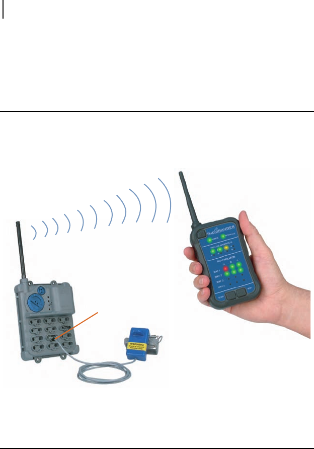
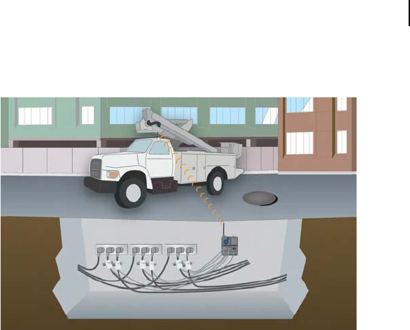
Connections and System Diagram
SEL fault indicators equipped with magnetic RADIORANGER Interface Probes
communicate their status to the Wireless Interface. Utility personnel can quickly
retrieve subsurface FCI status at street level via the wireless communications link
between the Wireless Interface and Remote Fault Reader.
Figure 1.1 RADIORANGER System
Accessories
For the most effective performance of the RADIORANGER in a vehicle, use the
optional accessory kit. The kit includes a windshield-mounting bracket for the Remote
Fault Reader and a magnetically-mounted remote antenna terminated with the
appropriate connector. The accessory kit comes in a hard carrying case for storage and
portability. Please consult an SEL sales representative or www.eosmfg.com for more
details.
Wireless Interface
R
ADIO
RANGER
Interface Probe
Fault Indicator
Remote Fault Reader

Date Code 20070308 RADIORANGER Instruction Manual
Introduction and Specifications
General Safety Information
1.3
General Safety Information
FCC Statements
This device complies with Part 15 of the FCC Rules. Operation is subject to the
following two conditions:
1. This device may not cause harmful interference.
2. This device must accept any interference received, including
interference that may cause undesired operation.
NOTE: This equipment has been tested and found to
comply with the limits for a Class B digital device,
pursuant to Part 15 of the FCC Rules. These limits are
designed to provide reasonable protection against
harmful interference when the equipment is operated in a
commercial environment.
NOTE: This equipment generates, uses, and can radiate
radio frequency energy. If not installed and used in
accordance with the instruction manual, it may cause
harmful interference to radio communications. Operation
of this equipment in a residential area may cause harmful
interference, in which case the user will be required to
correct the interference at his own expense.
IMPORTANT: Changes or modifications not expressly
approved by the party responsible for compliance could
void the user’s authority to operate the equipment.

RADIORANGER Instruction Manual Date Code 20070301
Introduction and Specifications
Specifications
1.4
Specifications
Operating Temperature Range
–40° to +85°C (–40° to +185°F)
5 to 95% humidity (noncondensing)
Electromagnetic Compatibility
Electrostatic
Discharge
Immunity: IEC 60255-22-2: 1996
[EN 60255-22-2: 1997]
IEC 61000-4-2: 1995
[EN 61000-4-2: 1995
+ A1:1999
+ A2:2001]
IEEE C37.90.3: 2001
Severity Level: 2, 4, 6,
8 kV contact
discharge; 2, 4, 8,
15 kV air discharge
Radio Frequency
Interference
Immunity: IEC 61000-4-3: 2002
[EN 61000-4-3: 2002]
IEC 60255-22-3: 2000
[EN 60255-22-3: 2001]
Severity Level: 10 V/m
IEEE C37.90.2: 2004
Severity Level: 35 V/m
Power Frequency
Magnetic Field
Immunity: IEC 61000-4-8: 2001
[EN 61000-4-8: 1994
+ A1:2001]
Severity Level:
100 A/m (60 Sec),
1000 A/m (3 Sec),
Level 5
Pulse Magnetic
Field Immunity: IEC 61000-4-9: 1993:
2001
[EN 61000-4-9: 1994
+ A1:2001]
Severity Level:
1000 A/m, Level 5
Damped Oscillatory
Magnetic Field
Immunity: IEC 61000-4-10: 2001
[EN 61000-4-10: 1994
+ A1:2001]
Severity Level:
100 A/m, Level 5
Radiated Radio
Frequency:
(900 MHz and
1.89 GHz
with modulation): ENV 50204: 1995,
10 V/m
Emissions: FCC Part 15, Class B
Environmental
Cold IEC 60068-2-1: 1990
+ A1:1993 + A2:1994
[EN 60068-2-1:1993
+ A2:1995]
Temperature
Shock on
SEL-8310: MIL-STD-810F
Method 503.4
–40°C (–40°F) and +70°C (158°F) with
temperature stabilized inside the unit.
Dry Heat: IEC 60068-2-2: 1974
+ A1:1993 + A2:1994
[EN 60068-2-2: 1993
+ A1:1995]
Damp Heat,
Cyclic: IEC 60068-2-30: 1980
+ A1:1985
[EN 60068-2-30:1999]
Vibration
Resistance: IEC 60255-21-1: 1988
[EN 60255-21-1: 1996
+ A1:1996]
Vibration
Endurance: Severity Class 1
Vibration
Response: Severity Class 2
Shock Resistance: IEC 60255-21-2: 1988
[EN 60255-21-2: 1996
+ A1:1996]
Bump Test: Severity Class 1
Shock Withstand: Severity Class 1
Shock Response: Severity Class 2

Date Code 20070301 RADIORANGER Instruction Manual
Introduction and Specifications
Specifications
1.5
Seismic (Quake
Response): IEC 60255-21-3: 1993
[EN 60255-21-3: 1995
+ A1:1995]
Severity Level: Class 2
IEC 60529: 2001
+ CRDG:2003
[BS EN 60529:1992
Protection Class
+ REAF:2004]
Severity Level: IP68
(4.5 m[15 feet])
SEL-8300 = IP54
SEL-8310 = IP58
Certifications
Listings:
This page intentionally left blank
Date Code 20070301 RADIORANGER Instruction Manual
Section 2
SEL-8300 Wireless Interface
Installation
Introduction
The SEL-8300 collects the status of up to 12 FCIs and communicates this data, upon
request, to an SEL-8310 Remote Fault Reader. Connect SEL FCIs equipped with a
magnetic probe output to the SEL-8300 via a keyed interface. Each magnetic probe
assembly includes a permanent magnet, which activates a Hall-effect sensor inside the
SEL-8300 to indicate the presence of an FCI probe, and two coils that deliver the FCI
trip and reset signals.
Figure 2.1 SEL-8300 Wireless Interface
Integral or remote antenna
Estimated 15-year product
life (about 40 faults/year)
Eight easy-to-set IDs
allow for application in
dense areas
Maintenance free:
System health
monitored remotely via
the Remote Fault Reader
Sealed, waterproof,
and IP58 rated
Connect up to 12 FCIs
wired with R
ADIO
RANGER
Interface Probes
RADIORANGER Instruction Manual Date Code 20070301
SEL-8300 Wireless Interface Installation
SEL-8300 Installation
2.2
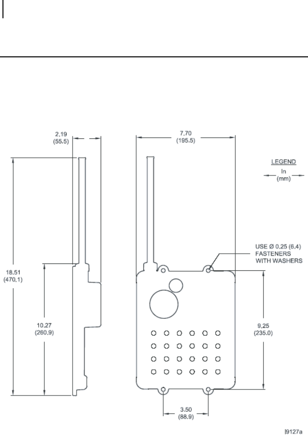
SEL-8300 Installation
Securely mount the SEL-8300 using four 1/4 inch-sized (6.0 mm) fasteners (not
included) designed for the surface to which the unit is being attached. To protect the
polycarbonate material of the Wireless Interface, use a flat washer in conjunction with
each fastener. We recommend that you install each fastener with a torque of 25 in/lbs
not to exceed 50 in/lbs. Install the SEL-8300 vertically to ensure optimal integral
antenna position and to maximize the life of the integral lithium battery.
Figure 2.2 SEL-8300 Dimensional Diagram
Standard SEL FCI lead lengths for magnetic probe outputs are 12 feet. Additional lead
lengths can be specified. Mount the SEL-8300 in a location that provides access to all
FCI magnetic probes. The RADIORANGER system communicates via 900 MHz; to
improve the range, install the SEL-8300 in locations with few RF impediments, such as
below a grate, if possible. Additionally, RF performance will be compromised in vaults
where flooding can occur. In vaults where flooding is common or where the FCI lead
Date Code 20070301 RADIORANGER Instruction Manual
SEL-8300 Wireless Interface Installation
SEL-8300 Installation
2.3
length is insufficient for optimal installation, order SEL-8300 units with an optional
remote antenna that provides an extra 15' of lead length. For best results, orient the
omni-directional antenna vertically so that it points toward the surface.
Figure 2.3 SEL-8300 Installed in Underground Vault
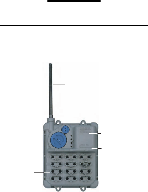
Power
The SEL-8300 is equipped with two dials: a power switch and an ID selector. The
smaller dial, labeled PWR, controls the power and has two positions. When the arrow is
pointing up, the SEL-8300 is on. When the arrow is pointing down, the unit is off. The
unit is shipped in the off position to conserve battery energy. The SEL-8300 is powered
by a 20-year shelf life lithium D cell. SEL designed the RADIORANGER system to
optimize battery life without compromising RF range. As such, the SEL-8300 is
expected to provide 15 years of service life under normal operating conditions.
Wireless Interface ID Selection
The larger dial on the SEL-8300, labeled ID, allows the user to select one of eight
wireless interface IDs. The Wireless Interface ID is part of the communications string
between the SEL-8300 and SEL-8310 and identifies which ID(s) the Remote Fault
Reader is communicating with. Therefore, the user should select different IDs if
installing multiple SEL-8300 units within a 150-foot radius. Doing so prevents
communications collisions with the SEL-8310, which could create a source of
confusion for the operator. It is important to situate the ID selector within one of the
eight detent positions in the SEL-8300 housing, to ensure proper ID selection.
Additionally, the ID could serve as a customer-specific naming convention to indicate
the nature of certain installations. For example, certain IDs could represent specific
vault configurations, voltages classes, etc. Another example of a naming convention is
to have odd-numbered IDs represent circuits arranged in a North-South direction, and
even-numbered IDs represent circuits arranged in an East-West direction.
RADIORANGER Instruction Manual Date Code 20070301
SEL-8300 Wireless Interface Installation
SEL FCI Connections
2.4
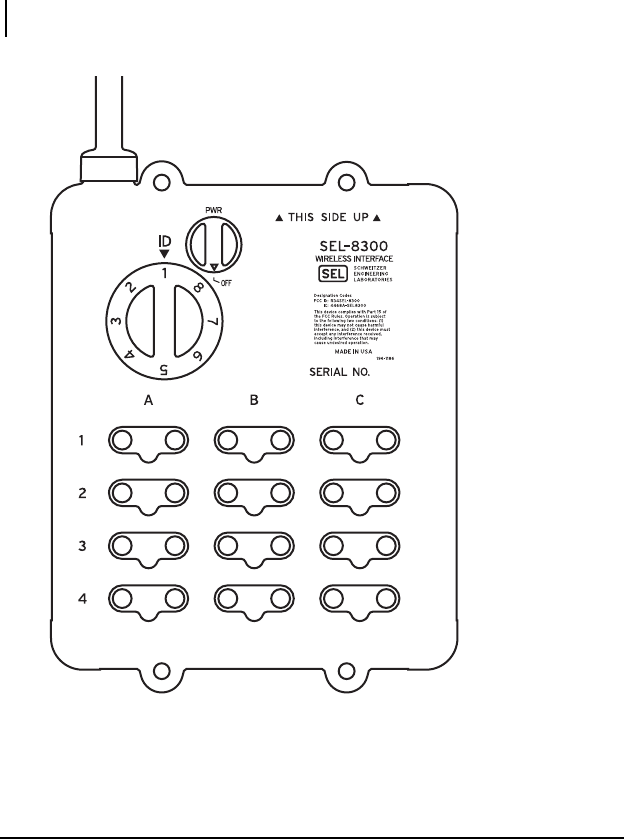
Figure 2.4 SEL-8300 Informational Diagram
SEL FCI Connections
The interface portion of the SEL-8300 is equipped with 12 FCI magnetic probe
interface ports aligned in a 4 x 3 matrix. The rows represent Ways (of a multiway
switch) 1, 2, 3, and 4, as read from top to bottom. The columns represent Phases A, B,
and C, as read from left to right. For example, a probe installed in the top left position
would correspond to Phase A of Way 1. The location of each FCI probe corresponds to
how the probes are displayed on the SEL-8310 Remote Fault Reader.
i4147a
Date Code 20070301 RADIORANGER Instruction Manual
SEL-8300 Wireless Interface Installation
Testing and Verifying Installation
2.5
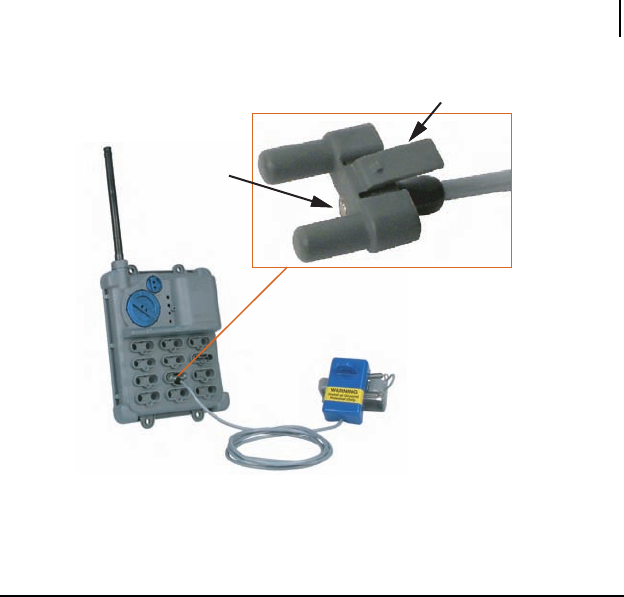
Figure 2.5 The Wireless Interface Has 12 Magnetic Probe Ports
Testing and Verifying Installation
After installing the SEL-8300 Wireless Interface, test its operation and verify the
communications range.
Perform the following steps to make sure all FCIs are connected properly to the
Wireless Interface.
Step 1. On the SEL-8300, turn the PWR dial to the ON position.
Step 2. Set the ID dial to any of the eight ID positions.
Step 3. Turn on the SEL-8310 Remote Fault Reader.
Step 4. Press the {Scan} button on the SEL-8310 and verify that it
communicates with the SEL-8300.
Step 5. Verify that the SEL-8310 display of the ID and FCI probes matches
the SEL-8300. See Section 3: SEL-8310 Remote Fault Reader
Operation for information on using the SEL-8310 Remote Fault
Reader.
Step 6. After the connection and status is correct, exit the subsurface vault
and verify that the communications range is adequate. Remember to
close the vault when determining communications range.
SEL-8300 Wireless Interface Fault Circuit Indicator (FCI)
Permanent magnet
to indicate installed
probe
Enlarged View of R
ADIO
RANGER Interface Probe
Clip to hold probe
in place

RADIORANGER Instruction Manual Date Code 20070301
SEL-8300 Wireless Interface Installation
Testing and Verifying Installation
2.6
Step 7. If the range is not adequate, move the SEL-8300 to a different
location, possibly a higher point in the vault.
Step 8. If moving the SEL-8300 does not provide adequate communications
range outside of the vault, you may need to order the SEL-8300 with
an external antenna. You can mount the external antenna near the top
of the vault.
Date Code 20070301 RADIORANGER Instruction Manual
Section 3
SEL-8310 Remote
Fault Reader Operation
Introduction
The SEL-8310 Remote Fault Reader provides a human-machine-interface (HMI) to
utility personnel charged with locating and isolating faulted sections of circuits. The
SEL-8310 is a handheld device that communicates wirelessly with any SEL-8300
Wireless Interface within range.
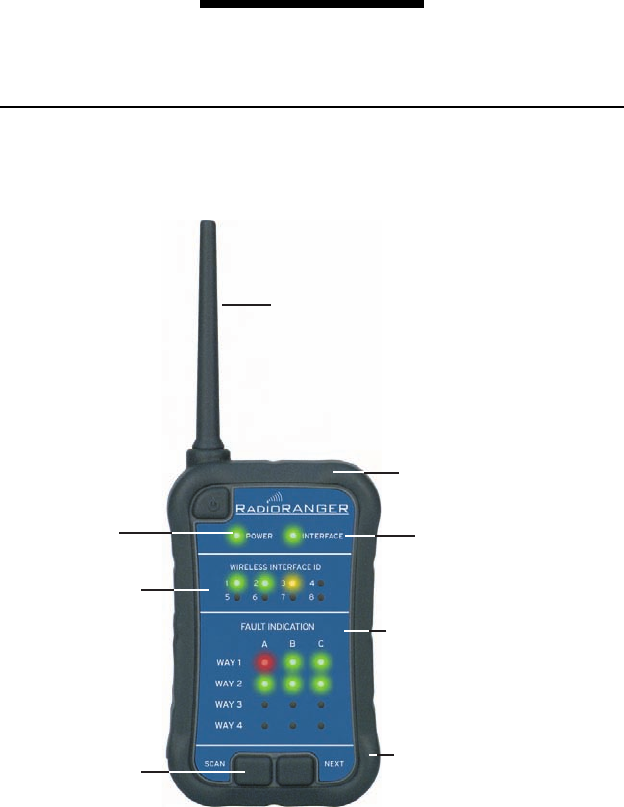
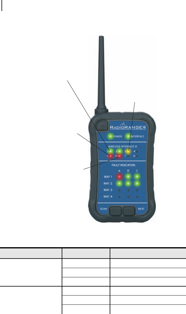
Figure 3.1 SEL-8310 Remote Fault Reader Front View
Flexible antenna
Remote Fault Reader
battery monitor Wireless Interface
health monitor
Displays up to eight
unique Wireless
Interface IDs
Easy-to-use keypad
Durable, buoyant
case rated to IP54
Communicates fault-indication
presence and status
Red—Tripped
Green—Untripped
Off—No fault indicator present
Operates on three alkaline
or rechargeable AA batteries

RADIORANGER Instruction Manual Date Code 20070301
SEL-8310 Remote Fault Reader Operation
Power Requirements
3.2
The SEL-8310 communicates the status of FCIs connected to any SEL-8300 within its
range via LEDs and various audible tones. The front display section labeled Fault
Indication has 12 LEDs arranged in a 4 x 3 matrix. The rows represent Ways 1, 2, 3,
and 4, as read from top to bottom. The columns represent Phases A, B, and C, as read
from left to right. For example, the status displayed in the top left position would
correspond to an FCI monitoring Phase A of Way 1. Each LED corresponds to the
position of each FCI probe installed in the SEL-8300.
Audio annunciation of FCI status is discussed in the manual sections, DIP Switch
Settings and Audio Indication, which follow.
In addition to displaying FCI status, the SEL-8310 also displays its status (ON or OFF)
and battery health through a POWER LED. The INTERFACE LED indicates the relative
health of the SEL-8300, conveying any self-test problems and the lithium battery
health.
The SEL-8300 is equipped with an ID selector dial that allows its radio to
communicate via one of eight IDs. This allows the RADIORANGER system to be used
in locations populated with multiple subsurface vaults within a small geographic area.
The SEL-8310 can display information from up to eight different SEL-8300 units
within range. The SEL-8310 identifies and differentiates each SEL-8300 within range
via a series of LEDs corresponding to each Wireless Interface ID.
Power Requirements
The SEL-8310 is powered from three 1.5 Volt, AA batteries (alkaline or rechargeable).
To open the battery cover, turn the fastener 1/4 turn counterclockwise. You can unhinge
and remove the battery cover to access the battery holder, DIP switches, and
programming header. Insert the batteries according to the polarity noted in the battery
holder. To replace the battery cover, insert the two tabs of the cover under the hinge and
lay the cover flat against the batteries. To secure the battery cover, turn the fastener 1/4
turn clockwise.
DIP Switch Settings
Access the eight-position DIP switch through the battery compartment. Refer to Power
Requirements for instructions on opening the battery cover. DIP Switches 1 and 2
adjust the audio mode of the SEL-8310, while DIP Switches 3 and 4 allow the unit to
operate on a single frequency. Note: Do not adjust DIP Switches 5, 6, 7, and 8. They
should remain in the OFF position.
The SEL-8310 supports four audio modes, selectable via the DIP switch block located
under the battery cover. Tabl e 3.1 describes the four audio modes and the DIP switch
settings used to select them.

Date Code 20070301 RADIORANGER Instruction Manual
SEL-8310 Remote Fault Reader Operation
DIP Switch Settings
3.3
The four audio modes are described briefly below. Refer to Audio Indication, for
specific audio indications corresponding to each setting.
Silent Mode—Annunciates Process Status and Button Press information only.
Summary Mode—Annunciates Process Status, Button Press, and FCI Status
Summary information only.
Morse Code Mode—Provides all audio indications. FCI Status Summary
information is followed by FCI Detail information annunciated in Morse
Code.
Row/Column Mode—Provides all audio indications. FCI Status Summary
information is followed by FCI Detail information annunciated in
Row/Column Mode.
All audio indications will be annunciated at the current volume control setting, with the
exception of HMI Adjust Mode indications.
You can configure the SEL-8310 for single frequency operation to allow two
SEL-8310 units to operate within the same area simultaneously, with each unit on a
different frequency. Ta ble 3.2 shows the DIP switch settings that enable this
functionality.
When DIP Switch 3 is in the ON position, DIP Switch 4 determines the single
frequency to be used. If DIP Switch 3 is in the OFF position, then DIP Switch 4 has no
effect. If using two SEL-8310 units in the same area, both units should have DIP
Switch 3 set to ON and one of the units should have DIP Switch 4 set to ON.
Table 3.1 Four Audio Modes Selectable With the DIP Switch Block
Audio Mode DIP Switch 1 DIP Switch 2
Silent Mode ON ON
Summary Mode ON OFF
Morse Code Mode OFF ON
Row/Column Mode OFF OFF
Table 3.2 DIP Switch Settings
Position of
Switch DIP Switch 3 Functionality DIP Switch 4
Functionality
OFF Single-Frequency Operation Disabled Use Base Frequency
ON Single-Frequency Operation Enabled Use Offset Frequency
RADIORANGER Instruction Manual Date Code 20070301
SEL-8310 Remote Fault Reader Operation
Audio Indication
3.4
Audio Indication
The SEL-8310 is equipped with a piezospeaker that produces four distinct audible
tones to supplement LED indications. The tones are denoted as pitches P1, P2, P3, and
P4 in this manual and are annunciated for either a short (50 ms) or long (150 ms)
duration. The tones or sequence of tones are depicted in Figure 3.2–Figure 3.14 and in
Table 3.5.
There are four basic categories of audible annunciation: Process Status, FCI Status
Summary, FCI Details, and Button Press. Additionally, a user can select from four
audio modes: Silent, Summary, Row/Column, or Morse Code Mode. These audio
modes are described in DIP Switch Settings.
Process Status
Process Status events are annunciated to provide feedback of SEL-8310 status. Each
type of event is described below.
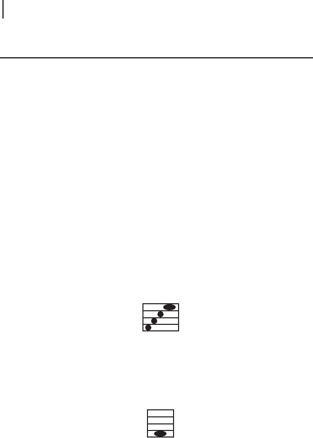
Power-Up
The Power-Up event is annunciated after a successful Power On Self-Test (POST) is
completed. It is a series of four tones, three short tones followed by one long tone,
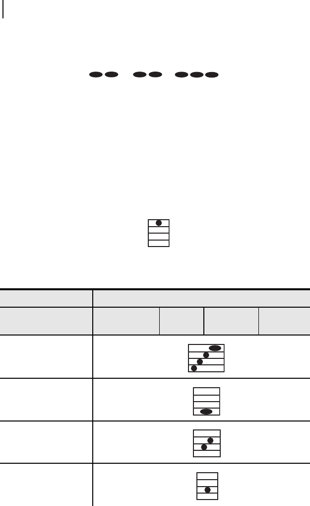
increasing in pitch.
Figure 3.2 Power-Up Audio Indication in All Audio Modes
POST (Power On Self-Test) Fail
The POST Fail event is annunciated if any of the self-tests fail during power up. This is
a single long tone as shown in Figure 3.3.
Figure 3.3 POST Fail Audio Indication in All Audio Modes
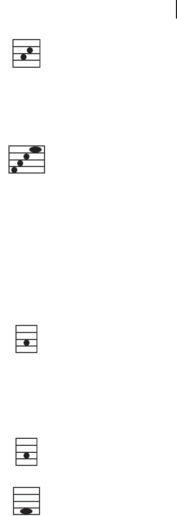
Scan Initiate
The Scan Initiate event is annunciated after the {Scan} button is pressed. It is a series of
two short tones, increasing in pitch.
P1
P2
P3
P4
P1
P2
P3
P4
Date Code 20070301 RADIORANGER Instruction Manual
SEL-8310 Remote Fault Reader Operation
Audio Indication
3.5
Figure 3.4 Scan Initiate Audio Indication in All Audio Modes
Scan Complete
The Scan Complete event is annunciated after a scan has completed. This is the same
tone sequence that plays at power-up.
Figure 3.5 Scan Complete Audio Indication in All Audio Modes
FCI Status Summary
The FCI Status Summary tones provide feedback as to the status of the faulted circuit
indicators connected to an SEL-8300 within range. The pitch and sequence of the tones
indicate whether any or none of the connected FCIs are in the tripped state and no
summary or detail sequence annunciation is already in progress.
Response Received
The Response Received tone will be annunciated during a scan whenever valid data are
received from an SEL-8300 within range. This is a single short tone.
Figure 3.6 Response Received Audio Indication in All Audio Modes
FCI Status Summary—Tripped FCI(s)
The Tripped FCI(s) status will be annunciated if the SEL-8310 receives valid data from
an SEL-8300 with at least one tripped FCI. This annunciation will occur following a
press of the {Next} button, if the next ID contains at least one tripped FCI.
Figure 3.7 FCI Status Summary–Tripped FCI(s) Indication in Silent Mode
Figure 3.8 FCI Status Summary–Tripped FCI(s) Indication in Summary,
Row/Column, or Morse Code Mode
P1
P2
P3
P4
P1
P2
P3
P4
P1
P2
P3
P4
P1
P2
P3
P4
P1
P2
P3
P4
RADIORANGER Instruction Manual Date Code 20070301
SEL-8310 Remote Fault Reader Operation
Audio Indication
3.6
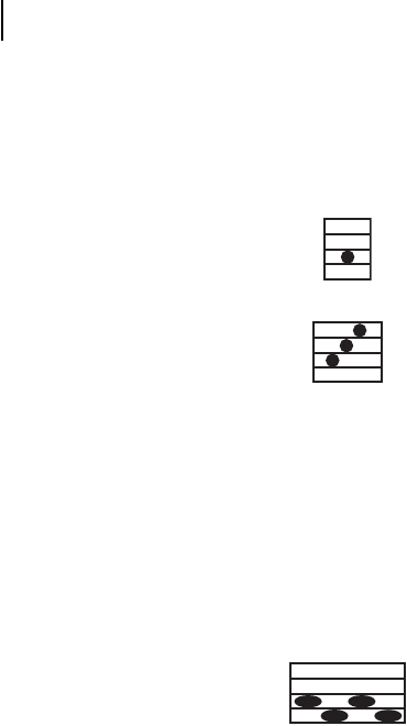
FCI Status Summary—No Tripped FCI(s)
The No Tripped FCI(s) status will be annunciated if the SEL-8310 receives valid data
from an SEL-8300 with no tripped FCIs. This annunciation will occur following a
press of the {Next} button, if the next ID contains no tripped FCI(s). As indicated in
Figure 3.9 and Figure 3.10, the annunciation will vary for most audible modes.
Figure 3.9 FCI Status Summary–No Tripped FCI(s) Indication in Silent Mode
Figure 3.10 FCI Status Summary–No Tripped FCI(s) Indication in Summary,
Row/Column, or Morse Code Mode
Data Collision
The Data Collision status will be annunciated if the SEL-8310 receives valid data from
two SEL-8300 units set to the same ID. This annunciation will sound after a scan when
the ID containing multiple SEL-8300 units is selected after pressing the {Next} button.
For more information on Data Collision see Scanning for and Retrieving Data from
SEL-8300 Units on page 3.10. This is a set of long tones alternating between two
pitches (high-low, high-low).
Figure 3.11 Data Collision Audio Indication in All Audio Modes
FCI Detail
If a user has configured the SEL-8310 for either Row/Column or Morse Code Modes,
the FCI Detail tones will be annunciated after the FCI Status Summary (see DIP Switch
Settings on page 3.2 for more information). These tones will indicate all of the tripped
phases on the lowest faulted Way. If more than one Way contains tripped FCIs, only the
status of the lowest Way with tripped FCIs will be annunciated.
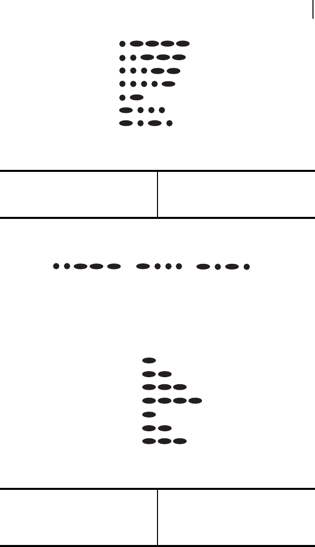
Morse Code Mode
If the current audio mode is Morse Code Mode, then the FCI Detail audio indication
will consist of the lowest Way that contains one or more faults (1, 2, 3, or 4), followed
by each faulted Phase in the Way (A, B, and C). The Morse Code dot-dash patterns for
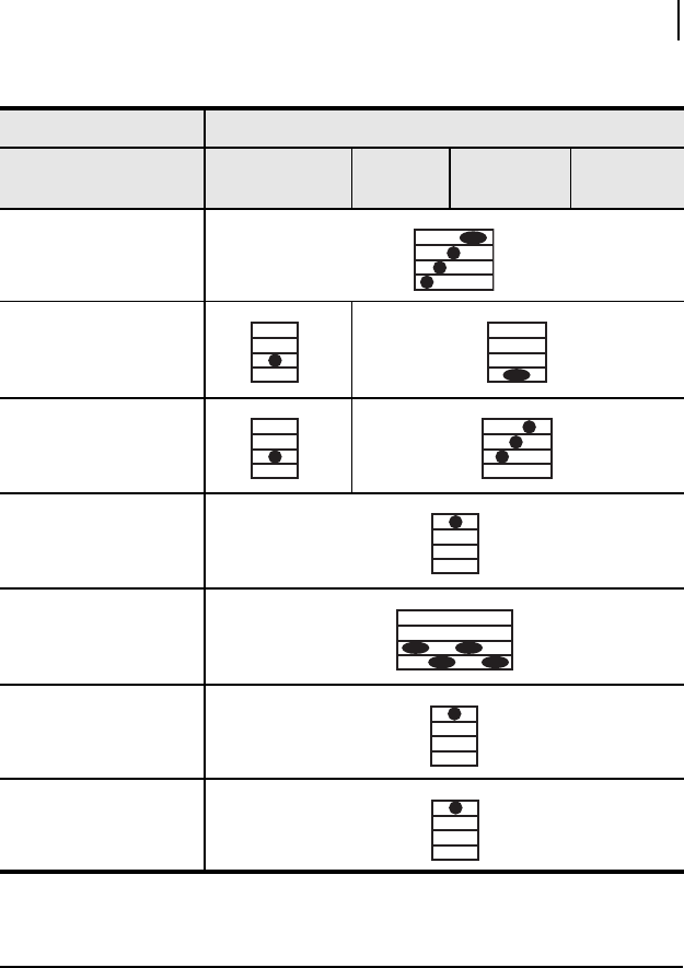
all possible Ways and Phases are shown in Figure 3.12.
P1
P2
P3
P4
P1
P2
P3
P4
P1
P2
P3
P4
Date Code 20070301 RADIORANGER Instruction Manual
SEL-8310 Remote Fault Reader Operation
Audio Indication
3.7
Figure 3.12 Morse Code Audio Mode Dot-Dash Patterns
For example, in Morse Code Mode, the FCI Detail audio indication
annunciated if Way 2 is the lowest Way containing a fault, and with Phases B
and C faulted would be:
Row/Column Mode
If the current audio mode is Row/Column Mode, then the FCI Detail audio indication
will consist of the Way number (row number on the display) that contains one or more
faults (1, 2, 3, or 4) followed by each fauled Phase (A, B, or C) in the Way represented
as a number, where the row and columns are annunciated as a series of dashes, as
shown below:
Figure 3.13 Row/Column Audio Mode Dot-Dash Patterns
Table 3.3 Duration of Audio Indications in Morse Code Mode
Dot Duration 65 ms
Dash Duration 195 ms
Pause Duration 65 ms
Table 3.4 Duration of Audio Indications in Row/Column Mode
Dash Duration 195 ms
Pause Duration 65 ms
Pause Duration Between Way and Phase
and Between Phases
390 ms
Way 1
Way 2
Way 3
Way 4
Phase A
Phase B
Phase C
Way 1
Way 2
Way 3
Way 4
Phase A
Phase B
Phase C
RADIORANGER Instruction Manual Date Code 20070301
SEL-8310 Remote Fault Reader Operation
Audio Indication
3.8
For example, in Row/Column Mode, the FCI Detail audio indication
annunciated if Way 2 is the lowest Way containing a fault, and with Phases B
and C faulted would be:
Button Press
The Button Press annunciation occurs under any of the following circumstances:
➤Either the {Scan} or {Next} button is pressed in HMI Adjust Mode
(see HMI Adjust Mode on page 3.13 for more details)
➤After the {Next} button is pressed in Normal Mode when there are no
data to display
➤The {Next} button is pressed in Silent Mode
➤Either the {Scan} or {Next} button is pressed with the SEL-8310 in
Low Power Mode
Figure 3.14 Button Press Audio Indication in all Modes
Table 3.5 Complete List of SEL-8310 Audio Indications (Sheet 1 of 2)
Audible Tones
SEL-8310 Status Silent Mode Summary
Mode
Row/Column
Mode
Morse Code
Mode
Power-Up
POST Fail
Scan Initiate
Response Received
P1
P2
P3
P4
P1
P2
P3
P4
P1
P2
P3
P4
P1
P2
P3
P4
P1
P2
P3
P4
Date Code 20070301 RADIORANGER Instruction Manual
SEL-8310 Remote Fault Reader Operation
Operation
3.9
Operation
The {Power} button is located in the top left corner of the SEL-8310. Pressing the
{Power} button causes the unit to enter a Power On Self-Test (POST) and alternates
illuminating all LEDs in solid green, solid yellow, and solid red for 0.75 seconds each.
Provided that the battery voltage is 3.0 Volts or above, it annunciates successful POST
with a four-tone scan. If the battery voltage is below 3.0 Volts, the device will turn off
to prevent damage to rechargeable batteries.
Scan Complete
FCI Status Summary—
Tripped FCIs
FCI Status Summary—No
Tripped FCIs
NEXT (No Data to Display)
Data Collision
NEXT (HMI Adjust Mode)
SCAN (HMI Adjust Mode)
Table 3.5 Complete List of SEL-8310 Audio Indications (Sheet 2 of 2)
Audible Tones
SEL-8310 Status Silent Mode Summary
Mode
Row/Column
Mode
Morse Code
Mode
P1
P2
P3
P4
P1
P2
P3
P4
P1
P2
P3
P4
P1
P2
P3
P4
P1
P2
P3
P4
P1
P2
P3
P4
P1
P2
P3
P4
P1
P2
P3
P4
P1
P2
P3
P4
RADIORANGER Instruction Manual Date Code 20070301
SEL-8310 Remote Fault Reader Operation
Operation
3.10
The POWER LED also indicates the relative battery life of the three 1.5 V (alkaline or
rechargeable) AA batteries required to power the SEL-8310, as well as any internal
RAM or Flash memory issues.
➤A solid green LED indicates the voltage is above 3.2 Volts.
➤A solid yellow LED indicates the voltage is at or below 3.2 Volts.
➤A flashing red LED indicates that either the RAM or Flash memory
self-check failed. Return any units exhibiting this annunciation to the
factory for analysis.
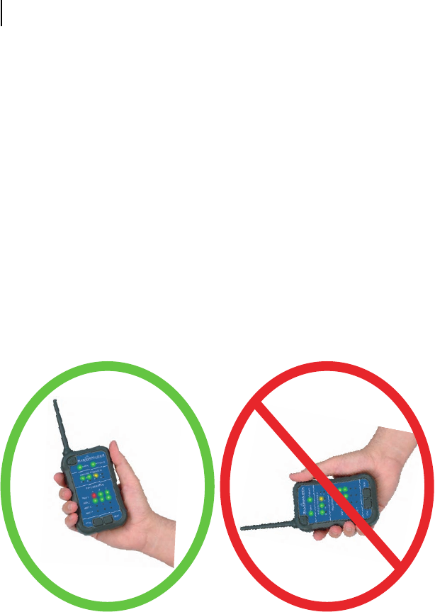
Proper Orientation of the SEL-8310
The SEL-8310 is equipped with an integral dipole antenna. To achieve optimal range
with SEL-8300 units mounted below grade, hold the SEL-8310 so that the antenna is
on a parallel plane to the antenna of the SEL-8300, refer to Figure 3.15. If the
SEL-8300 or its remote antenna is mounted properly, the SEL-8310 should be oriented
vertically with the antenna pointing toward the sky. Because of the antenna radiation
pattern, never point the SEL-8310 directly at a manhole or directly toward the location
of the SEL-8300. Doing so will dramatically reduce the range of the radio system and
result in poor performance.
Figure 3.15 Correct and Incorrect Positioning of the Remote Fault Reader
Scanning for and Retrieving Data from SEL-8300 Units
The {Scan} and {Next} buttons are located near the bottom of the SEL-8310. After the
unit is turned on and has successfully completed POST and memory tests, press the
{Scan} button to initiate a scan for SEL-8300 units within range. The Scan Initiate
annunciation, accompanied by pulsing yellow WIRELESS INTERFACE ID LEDs, indicates
the scan sequence has begun.

Date Code 20070301 RADIORANGER Instruction Manual
SEL-8310 Remote Fault Reader Operation
Operation
3.11
When a scan is initiated, the SEL-8310 clears any previously acquired data. If the
{Scan} button is pressed while a scan is in progress, the SEL-8310 aborts the current
scan and clears all acquired data. The SEL-8310 tests the battery voltage at the start of
each scan and updates the POWER LED as required. The scan sequence ends when one
of the following occurs:
➤A valid response is received for all eight wireless interface IDs.
➤The {Scan} button is pressed, which cancels the current scan and
begins another.
➤15.2 seconds pass after the first valid response from an SEL-8300.
➤The SEL-8310 enters the HMI Adjust Mode.
➤15 minutes pass after the {Scan} button is pressed and no valid
responses have been received.
After a scan is complete, the number of SEL-8300 units within range is depicted on the
SEL-8310 in the Wireless Interface ID section. The first valid SEL-8300 identified
with at least one tripped FCI flashes yellow and its FCI status is depicted in the Fault
Indication section of the SEL-8310. Use the {Next} button to cycle through and
display the status of all SEL-8300 units within range, and their connected FCIs.
Unless multiple SEL-8300 units are installed within a 150-foot range, a user will
probably only receive valid communications with one Wireless Interface per scan. In
vault-dense areas or installations that require multiple SEL-8300 units, a user may be
able to communicate with multiple SEL-8300 units, provided that the ID setting for
each Wireless Interface is not identical. If multiple SEL-8300 units with the same ID
setting are communicating to an SEL-8310, the SEL-8310 will display a collision
notification (see LED Legend—Wireless Interface ID Section). To differentiate between
two SEL-8300 units in this situation, users should move closer to the intended vault
and/or orient themselves between the SEL-8310 and the adjacent vault to exit the range
of, or block the signal of, the adjacent SEL-8300.
If two SEL-8310 Remote Fault Reader units are used in the same proximity, do not
scan both units simultaneously or the communications channel may become unstable.
In this situation, neither Remote Fault Reader may be able to properly communicate
with SEL-8300 units within range. However, two Remote Fault Readers can be used
simultaneously within the same range if the units are in Single Frequency Operation
Mode and are not operating at the same frequency. Please see DIP Switch Settings on
page 3.2 for more information on how to enable this mode.
RADIORANGER Instruction Manual Date Code 20070301
SEL-8310 Remote Fault Reader Operation
Operation
3.12
LED Legend—Wireless Interface ID Section
Figure 3.16 Wireless Interface ID LED Color Descriptions
Table 3.6 Remote Fault Reader LED Indication Description (Sheet 1 of 2)
LED Label Color Representation
Power Green Good SEL-8310 Battery
Yellow Weak SEL-8310 Battery
Red (Flashing) Self-Test Error
Interface (corresponds to
“Active” Wireless Interface
ID)
Green SEL-8300 in service < 12 years
Yellow SEL-8300 in service > 12 years
Red (Flashing) SEL-8300 imminent battery failure
Green (solid) LED = Valid communication with
an SEL-8300 set to the corresponding ID.
All FCIs connected to that SEL-8300 are in the
reset (unfaulted) position. Yellow (flashing) LED = The SEL-8300
(corresponding to the ID) is being
represented in the Fault Indication
section of the SEL-8310.
Red (solid) LED = Valid communication with
an SEL-8300 set to the corresponding ID.
At least one FCI connected to that SEL-8300
is in the tripped (faulted) position.
Yellow/Red (toggling) LED = At least two
SEL-8300 units are within range and are set
to the same ID. The status of two SEL-8300
units will be displayed in this situation one
when the yellow LED is flashing and the
other when the red LED is flashing. The
Interface and Fault Indication LEDs will display
the corresponding SEL-8300 data accordingly.

Date Code 20070301 RADIORANGER Instruction Manual
SEL-8310 Remote Fault Reader Operation
Operation
3.13
FCI Data Display
The status of each FCI is communicated to the SEL-8300 via a keyed, wired magnetic
probe interface. Each FCI will send either a Trip (faulted) or Reset (unfaulted) signal to
the SEL-8300 through this magnetic probe interface. The SEL-8300 communicates the
FCI data to the SEL-8310 via 900 MHz radio. The SEL-8310 then displays FCI status
information under the Fault Indication section. A red LED indicates a tripped FCI,
whereas a green LED indicates a reset FCI. By providing both tripped and reset
indications, the RADIORANGER system allows the user to retrieve the status of the
FCIs beyond the fault to validate the fault location.
Low Power Mode
To preserve the battery, the SEL-8310 will enter Low Power Mode one minute after
scan termination or one minute after the last {Next} button press, whichever occurs
later. When the SEL-8310 enters Low Power Mode, all address and FCI Status LEDs
turn off. The POWER LED will emit short pulses, 2.25 seconds apart, in the color in
which the POWER LED was illuminated prior to entering Low Power Mode. While the
SEL-8310 is in Low Power Mode, pressing either the {Scan} or the {Next} button
returns the device to the normal mode and displays the same data that was displayed
prior to entering Low Power Mode. All the data received from the last scan is still
available via the {Next} button. The SEL-8310 will reenter Low Power Mode one
minute after Low Power Mode termination or one minute after the last {Next} button
press, whichever occurs later.
HMI Adjust Mode
Adjust the SEL-8310 volume and brightness to accommodate user and situational
preference. Pressing and holding both the {Scan} and {Next} buttons simultaneously
for one second places the SEL-8310 in the HMI Adjust Mode. In this mode, the FAULT
INDICATION LEDs are turned off. The WIRELESS INTERFACE ID LEDs will now
Wireless Interface ID Yellow (short pulse) Scan in progress, no response
received
Yellow (flashing) “Active” Wireless Interface ID
Red (solid) Indicates communication with an
SEL-8300 with corresponding
ID—connected to at least one
tripped FCI
Green (solid) Indicates communication to an
SEL-8300 with corresponding
ID—connected to no tripped FCIs
Table 3.6 Remote Fault Reader LED Indication Description (Sheet 2 of 2)
LED Label Color Representation

RADIORANGER Instruction Manual Date Code 20070301
SEL-8310 Remote Fault Reader Operation
Operation
3.14
correspond to speaker volume and LED intensity. The SEL-8310 will exit the HMI
Adjust Mode five seconds after the last button press or after pressing and holding both
the {Scan} and {Next} buttons simultaneously for one second. Following HMI Adjust
Mode termination, the SEL-8310 reenters Normal Mode. The same data displayed
prior to entering HMI Adjust Mode will be available.
While the device is in the HMI Adjust Mode, the {Scan} button cycles through the four
possible volume levels. The volume level is represented by solid yellow WIRELESS
INTERFACE ID LEDs in a bar chart style from left to right. A single LED bar represents
no volume; four LED bars represent maximum volume, which is the default. Each
{Scan} button press selects the next highest volume level until it reaches the maximum
volume level. At that point, pressing the {Scan} button again takes the unit back to the
lowest volume level. When the SEL-8310 exits the HMI Adjust Mode, any adjustments
made to the volume level are updated in the Flash memory and are active when the
Normal Mode resumes.
While the device is in the HMI Adjust Mode, the {Next} button cycles through three
possible LED brightness levels. The solid yellow LEDs that represent the volume level
also adjust their brightness in response to presses of the {Next} button. Each {Next}
button press selects the next highest brightness level until the maximum level is
reached. At that point, pressing the {Next} button again selects the lowest brightness
level. When the device exits the HMI Adjust Mode, any adjustments made to the
brightness level are updated in the Flash memory and are active when the Normal
Mode resumes.

Date Code 20070301 RADIORANGER Instruction Manual
Section 4
Testing and Troubleshooting
Introduction
This section provides guidelines for testing and troubleshooting the RADIORANGER
system. Self-tests and troubleshooting procedures are included.
Self-Tests
The SEL-8300 and SEL-8310 perform periodic self-tests to verify proper operation. A
self-test failure of either product is indicated via the Remote Fault Reader LED display.
A flashing red POWER LED indicates an SEL-8310 self-test failure. A flashing red
INTERFACE LED indicates an SEL-8300 self-test failure. Please contact the factory to
service any device indicating a self-test failure.
Troubleshooting the SEL-8300
Troubleshooting issues related to the SEL-8300 are primarily related to system
communication and battery life. Tabl e 4.1 lists common troubleshooting issues and
causes/remedies.
Table 4.1 Troubleshooting the SEL-8300 (Sheet 1 of 2)
Issue Possible Cause/Response
SEL-8300 is not identified after
the SEL-8310 {Scan} button is
pressed
Ensure the unit is turned on.
Ensure ID selector is situated in a detent and rescan.
Ensure antenna is oriented vertically and not sub-
merged.
Ensure the SEL-8310 is within proper range.
INTERFACE LED is solid yellow
on the SEL-8310
Indicates the SEL-8300 has been in service for 12
years or longer.
INTERFACE LED is pulsing red
on the SEL-8310
Indicates the SEL-8300 battery is weak. Order a
replacement SEL-8300.
RADIORANGER Instruction Manual Date Code 20070301
Testing and Troubleshooting
Troubleshooting the SEL-8310
4.2
Troubleshooting the SEL-8310
Troubleshooting issues related to the SEL-8310 are primarily related to system
communication, battery life, and LED and audible indications. Table 4.2 lists common
troubleshooting issues and causes/remedies.
INTERFACE LED is flashing red
on the SEL-8310
If the LED is flashing red during a collision (i.e.,
SEL-8310 is communicating with two SEL-8300
units), this indicates the SEL-8300 battery is weak.
If the LED is flashing red without a collision, it indi-
cates that a self-test has failed. Please consult the fac-
tory.
Wireless ID is displayed, but FCI
status is not
Ensure that probes are interfaced and mated correctly.
Ensure the unit is turned on.
Wireless ID is displayed, but ID
is inconsistent with ID setting
Ensure the unit is turned on.
Ensure the ID selector is situated within 1 of the 8
detents.
Ensure that the antenna is unobstructed.
Table 4.2 Troubleshooting the SEL-8310 (Sheet 1 of 2)
Issue Possible Cause/Response
Nothing happens after pressing the
{Power} button
Check that batteries have sufficient voltage and
are installed with correct polarity.
SEL-8310 illuminates all LEDs in
green, yellow, and red sequence and
then shuts off
Replace batteries.
POWER LED is yellow Battery is weak.
POWER LED is flashing red Self-test failure. Contact the factory for assis-
tance.
LED brightness is not optimal Adjust LED brightness in HMI Adjust Mode.
Volume level is not optimal Adjust the volume level in HMI Adjust Mode.
Multiple ID and FCI data are dis-
played that are inconsistent with the
actual system within range
Ensure that DIP Switches 5–8 are in the OFF
position.
Audible annunciation is silent Adjust volume level in HMI Adjust Mode.
Table 4.1 Troubleshooting the SEL-8300 (Sheet 2 of 2)
Issue Possible Cause/Response

Date Code 20070301 RADIORANGER Instruction Manual
Testing and Troubleshooting
Factory Assistance
4.3
Factory Assistance
We appreciate your interest in SEL products and services. If you have questions or
comments, please contact us at:
E.O. Schweitzer Manufacturing Division of SEL
450 Enterprise Way
Lake Zurich, IL USA 60047-6722
Telephone: (847) 362-8304
Fax: (847) 362-8396
Internet: www.eosmfg.com
Audible annunciation contains a
series of tones
Device may be in Morse Code or Row/Column
Mode. Check DIP switch settings on positions 1
and 2.
Poor range between SEL-8300 and
SEL-8310
Ensure the SEL-8300 antenna is unobstructed.
Ensure the SEL-8310 is oriented properly
(antenna is oriented vertically).
Table 4.2 Troubleshooting the SEL-8310 (Sheet 2 of 2)
Issue Possible Cause/Response
This page intentionally left blank

Date Code 20070301 RADIORANGER Instruction Manual
Appendix A
Firmware and
Manual Versions
Firmware
This manual covers the RADIORANGER system containing firmware bearing the
firmware version numbers listed in Tabl e A .1. This table also lists a description of
modifications and the instruction manual date code that corresponds to firmware
versions. The most recent firmware version is listed first.
Table A.1 Firmware Revision History
Firmware Identification (FID) Numbers Description of Changes
Manual
Date Code
SEL-8310-R100-V0-Z001001-D20070320
SEL-8300-R100-V0-Z001001-D20070320
Original release 20070320

RADIORANGER Instruction Manual Date Code 20070301
Firmware and Manual Versions
Instruction Manual
A.2
Instruction Manual
The date code at the bottom of each page of this manual reflects the creation or revision
date.
Table A.2 lists the instruction manual release dates and a description of modifications.
The most recent instruction manual revisions are listed at the top.
Table A.2 Instruction Manual Revision History
Revision
Date Summary of Revisions
20070320 Date of Initial Release.