Schwinn 202 Assembly Manual 101C Schwinn® Upright Exercise Bike
Schwinn-202-Users-Manual-358990 schwinn-202-users-manual-358990
202 SCH_202_AM_web
202 5d51f5cf-27c7-43d0-a722-82ea1b9048c3 Schwinn Exercise Bike 202 User Guide |
2015-05-15
: Schwinn Schwinn-202-Assembly-Manual-718335 schwinn-202-assembly-manual-718335 schwinn pdf
Open the PDF directly: View PDF ![]() .
.
Page Count: 17
- Assembly Instructions
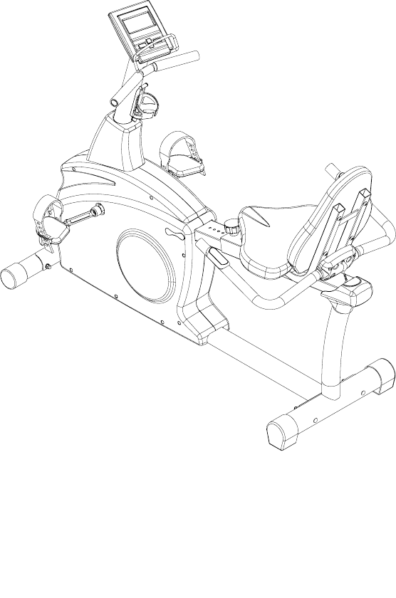
202 Schwinn® Recumbent Exercise Bike
Parts List
Full Size Hardware Chart
Product Illustration
Assembly Instructions
202 Recumbent Exercise
Bike
IMPORTANT PRECAUTIONS
WARNING: To reduce the risk of serious injury, please read the following
precautions before using the Schwinn 202.
1. It is the responsibility of the owner to ensure that all users of this equipment
are adequately informed of all precautions.
2. Read all instructions in this manual and in the accompanying literature and
follow them carefully before using the equipment.
3. If you feel pain or dizziness at any time while exercising, stop immediately and
consult your physician.
4. Use this equipment only on a solid level surface. Cover the floor or carpet
beneath this equipment for protection.
5. Inspect and tighten all parts often. Replace any worn parts immediately.
6. Keep small children and pets away from this equipment at all times.
7. Always wear athletic shoes for foot protection. Do not wear loose or dangling
clothing while using exercise bicycle.
8. Care should be taken when mounting or dismounting the exercise bicycle.
9. Read all warnings posted on the exercise bicycle.
10. User weight limit on the Schwinn 202 is 300 lbs.
This Schwinn 202 is intended for home use only. Do not use this equipment in
any non-residential environment.
WARNING: Before beginning this or any exercise program, consult your
physician. This is especially important for persons over the age of 35 or persons
with pre-existing health problems. Read all instructions before using. We
assume no responsibility for personal injury or property damage sustained by or
through the use of this product.
202 Schwinn Recumbent Bike Parts List,
Hardware Chart, and Assembly Instructions
Assembly of the 202 Recumbent Bike is divided into 5 easy stages; each
comprised of only a few setup steps. Before proceeding with the assembly,
please read over the easy to follow instructions to familiarize yourself with the
process.
• A flat area of 5’ x 7’ is suggested to assemble the 202 exercise bike.
• You will need the following tools to complete the assembly:
5mm Allen wrench (supplied)
Open wrench 13mm, 14mm, 15mm (supplied)
Phillips screwdriver (supplied)
Also, to ensure quick and easy set up of the 202 Recumbent Bike, please verify
the size and quantity of each of the enclosed assembly hardware. Included is a
handy full size hardware chart and parts list of each of the required assembly
hardware. Simply match up the corresponding hardware to each full size
drawing.
Parts List
Check Quantity Description Reference #
__ 8 Allen Bolt M8 x P1.25 x 45mm 1
__ 15 Flat Washer 2
__ 1 Seat Pin Adjustment Knob 3
__ 1 Seat 4
__ 1 Seat Back 5
__ 1 Handlebar Assembly 6
__ 8 Flat Washer ф8*ф16*2T 7
__ 1 Seat Frame Assembly 8
__ 1 Seat Rail 9
__ 1 Rear Stabilizer Tube 10
__ 1 End Cap (for #9) 11
__ 1 Buffer 12
__ 1 Buffer Plate 13
__ 2 Flat Washer for 12/13 14
__ 2 Screw for 12/13 15
__ 2 Carriage Bolt M8 x P1.25 x 75mm 16
__ 1 Front Stabilizer Tube (w/wheels) 17
__ 1pr Pedal Strap (Left & Right) 18
__ 8 Curved Washer 19
__ 4 Acorn Nut 20
__ 1pr Pedals (Left & Right) 21
__ 19 Allen Bolt M8 x P1.25 x 16mm 22
__ 2 Bolt Cover 23
__ 2 Carriage Bolt M8 x P1.25 x 90mm 24
__ 1 Computer Cable (Lower) 25
__ 1 HR Cable (Lower) 26
__ 1 Console Mast Cover 27
__ 1 Computer Cable (Upper) 28
__ 1 HR Cable (Upper) 29
__ 1 Console Mast 30
__ 1 Main Unit 31
__ 1 Lower Base Frame 32
__ 4 Computer Mounting Screws 33
__ 1 Computer 34
__ 1 HR Cable (Seat Rail) 47
__ 2 Water Bottle Cage Mounting Screws 56
__ 1 Water Bottle Cage 57
__ 1 AC Adapter 50
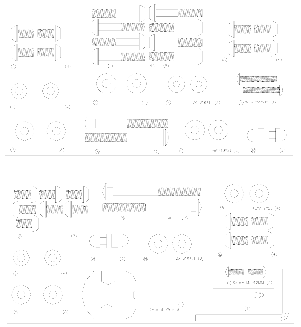
Hardware Chart
Allen Bolt M8xP1.25x16mm
Stage#2
Allen Bolt M8xP1.25x mm
Note: Please verify you have all correct parts and quantities before assembling
unit.
If you are missing items, are short quantities, or have damaged components,
please call 1-800-4-MY-HOME for assistance.
Flat Washer for ф8*ф16*2T
Flat Washerф8*ф19*2T
Allen Bolt M8xP1.25x16mm
Flat Washerф8*ф19*2T Flat Washer
Carriage Bolt M8xP1.25x75mm Curved Washer
Stage#3
Acorn Nut M8
Stage#1
Flat Washerф8*ф19*2T
Flat Washer ф8*ф16*2T
Allen Bolt M8xP1.25x16mm
Stage#4
Curved Washer
Acorn Nut M8
Carriage Bolt M8xP1.25x mm
Allen Bolt M8xP1.25x16mm
Curved Washer
Stage#5
Allen Key
Screwdriver
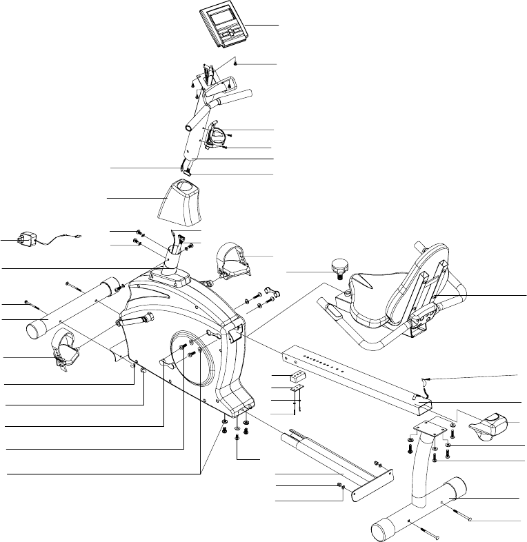
202 Assembly Drawing with Reference
Numbers
30
2
22
23
22
20
19
32
31
20
19
18
16
17
28
21
22 26
19 25
29
27
11
24
10
22
2
8
47
9
56
57
33
34
58
3
15
14
13
12
Replacement Parts List
Reference # Description
3 Seat Pin Adjustment Knob
4 Seat
5 Seat Back
6 Handlebar Assembly
9 Seat Rail
10 Rear Stabilizer Tube
11 Seat Rail End Cap
12 Buffer
13 Buffer Plate
14 Flat Washer
15 Screws
16 Carriage Bolt M8 x P1.25 x 75mm
17 Front Stabilizer Tube (w/wheels)
20 Acorn Nut
21 Pedals (Left & Right)
22 Allen Bolt M8 x P1.25 x 16mm
23 Bolt Cover
24 Carriage Bolt M8 x P1.25 x 90mm
25 Computer Cable (Lower)
26 HR Cable (Lower)
27 Console Mast Cover
28 Computer Cable (Upper)
29 HR Cable (Upper)
33 Computer Mounting Screws
ottle Cage Mounting Screw
30 Console Mast
32 Lower Base Frame
34 Computer
56 Water B
57 Water Bottle Cage
Instructions
IMPORTANT!: To ensure ease of assembly please verify the size and
quantity of all the required assembly hardware and parts with the enclosed
parts list and full size hardware chart.
b ken d wn inEach step of the assembly process has been ro o to s o 5 ea y-to-f llow
e.
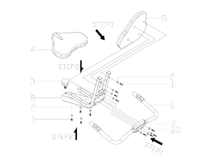
Assembly Stage #1
Assemble Seat and Handle Bar
Assembly hardware required: (8) M8 Allen Bolts 45 mm long (item #1)
(8) Flat Washers Ø8*Ø19*2T (item #2)
(4) M8 Allen Bolts 16 mm long (item #22)
(4)Flat Washer Ø8* Ø 16*2T(item #7)
Step 1: Attach HANDLEBAR ASSEMBLY (#6) to SEAT FRAME (#8) with the 4
ALLEN BOLTS (#22) and 4 FLAT WASHERS (#7). Tighten bolts with the
provided Allen wrench.
Step 2: Attach SEAT (#4) to SEAT FRAME (#8) with 4 ALLEN BOLTS (#1) and 4
WASHERS (#2). Tighten Bolts.
stages. Please take just a few moments to read over these instructions to
familiarize yourself with the process to make assembly quick and trouble-fre
TS Step 3: Attach SEAT BAC ) with 4 ALLEN BOL
(#1) and 4 WASHERS (#2). Tighten Bolts.
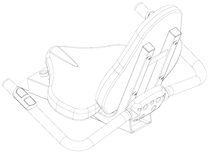
Note: Finished seat should look like picture below:
K (#5) to SEAT FRAME (#8
l to Seat Assembly
.
Assembly hardware required: (4) M8 Allen Bolts 16mm (item #22)
(4) Flat Washers Ø8 * Ø19 * 2T(item#2)
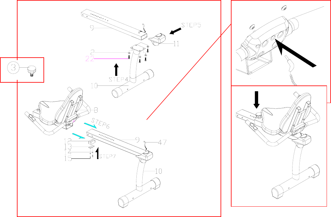
Step 4: Attach SEAT RAIL (#9) to REAR STABILIZER TUBE (#10) with 4 FLAT
WASHERS (#2) and 4 ALLEN BOLTS (#22). Tighten bolts.
Step 5: Place END CAP (#11) on the end of the SEAT RAIL (#9). Make sure the
HR CABLE (#47) is strung through the exit slot on the SEAT RAIL before end cap is
secured.
Step 6: Insert SEAT PIN ADJUSTMENT KNOB (#3) into SEAT FRAME (#8).
Slide the seat assembly from stage 1 onto the SEAT RAIL (#9). Tighten seat
assembly to the rail with the SEAT PIN ADJUSTMENT KNOB (#3). Insert HR
CABLE (#47) into HR input on the back of the seat assembly.
Step 7: Attach BUFFER (#12), BUFFER PLATE (#13), FLAT WASHER (#14) and
SCREWS (#15) to the bottom of the seat rail as illustrated above.
Assembly Stage #2
Attach Rear Stabilizer and Seat Rai
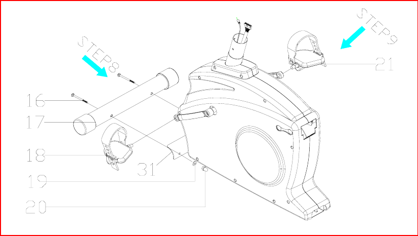
Attach Front Stabilizer Tube and Pedals to Main Unit
Assembly Hardware Required: ) M8 Bolt 75mm long (item #16)
(2) Curved Washers (item #19)
Acorn Nut (item #20)
Step 8: Attach FRONT STABILIZER TUBE (#17) to the MAIN UNIT (#31) with
the M8 BOLT 75mm (#16), CURVED WASHER (#19), and ACORN NUT (#20).
Tighten Bolts with provided wrench.
Step 9: Attach RIGHT PEDAL (#21) to the right crank arm on the MAIN UNIT
read
L. The threading on the left pedal
ing of the threads be
areful to use the proper pedal.
Assembly Stage #3
(2
(2)
(#31). Thread the pedal onto the crank arm and then tighten with pedal wrench.
Attach LEFT PEDAL (#21) to the left crank arm on the MAIN UNIT (#31). Th
the pedal onto the crank arm and then tighten with pedal wrench. Note: There is a
right pedal and a left pedal, marked by R and
is reversed from the right pedal. Counterclockwise rotation tightens while
Clockwise rotation loosens on the left pedal. To avoid stripp
c
Attach PEDAL STRAPS (#18) to each PEDAL (#21). Again, each strap is labeled
with an R or an L corresponding to the right and left pedal straps.
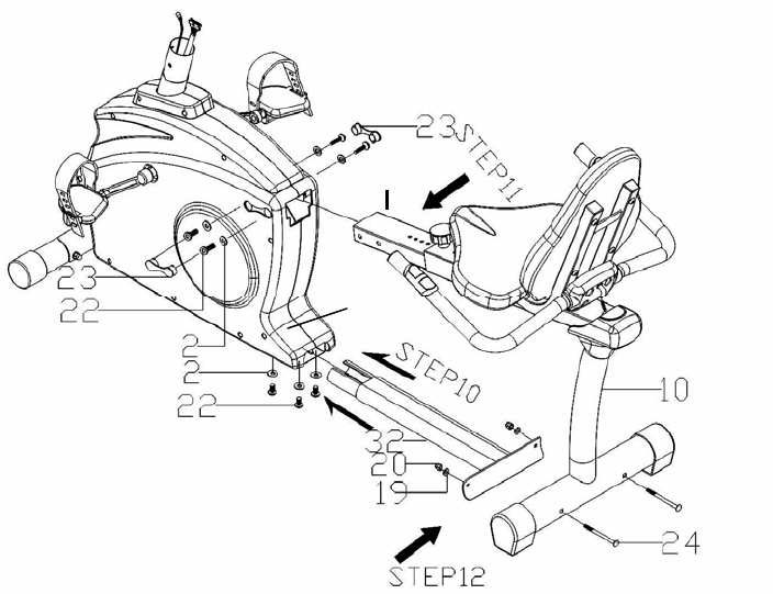
Assembly Stage #4
at Rail and Lower Base Frame to MAttach Se ain Unit
9
#22) Assembly Hardware Required: (7) Allen Bolts 16 mm long (item
(3) Flat Washers (item #2)
(2) Allen Bolts 90 mm long (item #24)
(2) Curved Washers (item #19)
(4) Flat Washer (item #7)
Ste
wit n
unt
31
p 10: Slide the LOWER BASE FRAME (#32) into the MAIN UNIT (#31), attach
h 3, 16mm BOLTS (#22) and 3 FLAT WASHERS (#2). Do not completely tighte
il after step 12.

Before proceeding to step 11 please complete the
following steps. Failure to do so could lead to
damage to the handgrip heart rate wires!
1) Remove END CAP (#11) from the end of the seat rail. The coiled wire seen
above the seat rail needs to be re-routed out the back of the seat rail .
2) Pull the wire from the back of the seat rail until the male prong is flush with
the front of the seat rail. Connec e cables from MAIN UNIT and Seat Rail.
Tape can be used around the attachment of the two cable ends to ensure that
they do not become disconnected.
3) Gently pull the excess cable f of the seat tube so that the cable
running through the seat rail is taut. Be careful not to pull apart the cable
connection you have just made. Slide the seat rail with seat assembly gently
into the main unit, while pulling the cable tight from the back of the seat rail.
Slide the seat rail slowly into the main unit. Using a flashlight check to make
sure that the cable is not
- IMPORTANT -
t th
rom the back
protruding from the bottom of the seat rail as it slides
into main unit. CAUTION! If the wire is protruding from the bottom of
the seat rail it may be severed or damaged when the seat rail is fully
inserted into the main unit! This may result in a non-functioning
handgrip heart rate. Carefully slide the seat rail until the slots in the side of
the rail line up with the holes in the main unit.
to AIN
LT
OVER (23) ver B LTS (
Ste h 2
90mm LONG BOLTS (#24), 2 CURVED WASHERS (#19), and 2 ACORN NUTS
tep 12b: Feed the excess coiled wire from the back end of the seat rail through the hole
n top of the seat rail until about 6 inches of coiled wire is on the outside of the seat rail.
ttach the end of the wire to the back of the handlebar assembly. Feed the remaining
xcess wire into the seat rail and replace the end cap on the end of the seat rail. After
ompleting assembly stage 5 verify that the handgrip heart rate works by hitting manual
art and then placing your hand on the grip heart pad located on the handlebars. Verify
at a heart rate registers on the computer panel after several seconds.
Step 11: Attach SEAT RAIL (#9) M UNIT (#31) with 4, 16 mm BOLTS (#22)
and 4 FLAT WASHERS (#7). Again do not tighten until after step 12. Place BO
C S o O #22) in MAIN UNIT (#31).
p 12: Attach REAR STABILIZER TUBE (#10) to BASE FRAME (#32) wit
(#20). Tighten with provided wrench. Tighten Allen bolts from steps 10 and 11 with
provided Allen wrench.
S
o
A
e
c
st
th
Assembly Stage #5
Attach Console Mast to Main Unit
31
22
19
27
26
25
29 56
57
30
28
STEP13
33
34
STEP14
58
STEP15
31
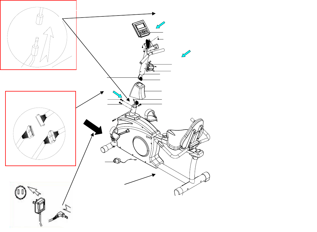
tep 13: Run CONSOLE MAST (#30) through the CONSOLE MAST COVER (#27)
nd onto the MAIN UNIT (#31). Before fastening the CONSOLE MAST, attach both
R CABLES (#29 & #26) as well as the COMPUTER CABLE (#28 & #25). To easily
omplete this step it would be helpful to have someone hold the CONSOLE MAST (#30)
nd CONSOLE MAST COVER (#27) while connecting the cables. Fasten with 4
OLTS (#22) and 4 CURVED WASHERS (#19). Tighten with provided Allen wrench.
tep 14: Attach WATER BOTTLE CAGE (#57) to CONSOLE MAST (#30) with
CREWS (#56). Tighten with Phillips head screwdriver.
Assembly Hardware Required: (4) Allen Bolts 16 mm long (item #22)
(4) Curved Washers (item #19)
(4) Computer Screws (item #33)
(2) Water Bottle Cage Screws M5*12 mm (item
#56)
S
a
H
c
a
B
S
S
31
Step 16
Step 15: Attach UPPER COMPUTER CABLE (#28) and HR CABLE (#29) to under
de of COMPUTER (#34). Place COMPUTER (#34) on top of CONSOLE MAST
(#30), the reading rack UTER. Attach
COMPUTER to CONS G SCREWS (#33).
(In computer back) Tig
Step 16: Plug power adapter into the wall and into the recumbent bike. The power input
on the bike is located at the front end of the MAIN UNIT (#31) just above the FRONT
STBILIZER TUBE (#17)
Seat Adjustment
For best results, the seat should be adjusted for your height.
1. Unlock “seat locking” mechanism.
2. Adjust seat location so that with feet on the pedals, you can comfortably reach pedal at
full extension.
You’re finished and now you can begin to reach your fitness goals!
Please reference the Owner’s Manual for information regarding computer
operation, product maintenance, warranty information, and general fitness and
si should wrap around the bottom of the COMP
OLE MAST with COMPUTER MOUNTIN
hten with Phillips head screwdriver.
That’s it!
exercise guidelines.
Troubleshooting the Schwinn 202 Recumbent
nd connector orientation
made to the computer.
ROBLEM: No Heart Rate on computer…
OLUTION): 1. Check the connections made at the computer and
handlebars
2. If heart rate still fails to work call 1-800-4-MY-HOME for
assistance.
ROBLEM: Bike will not sit level…
OLUTION): 1. Adjust the levelers on the rear stabilizer.
Exercise Bike
IP: Use assembly diagram(s) as reference when troubleshooting unit. T
PROBLEM: Computer will not start, function, or is blank…
(SOLUTION): 1. Ensure the unit is plugged into a 110v outlet.
2. Check the wiring connections a
3. Confirm that wiring (cable assembly) has not been
damaged
4. If computer still fails to start please call 1-800-4-MY-
HOME for assistance.
P
(S
P
(S
