Scientech Electronics WS3N Outdoor Siren User Manual WS 30S manual 11262010
Scientech Electronics Co., Ltd. Outdoor Siren WS 30S manual 11262010
User Manual

Wireless Solar Siren with Strobe, WS-30S
INTRODUCTION
The WS-30S is a wireless solar siren with strobe
dedicated for LS-30 alarm system. With special designed
strobe magnifier, viewing angle and flashing pattern, it
provides the users with a fresh experience. The WS-30S
is powered by a solar panel which charges the internal
battery. When the battery is fully charged, the WS-30S
can work for one month without sunshine.
With built in transmitter and receiver, it sends heartbeat
signal once an hour, if the LS-30 Base Unit fails to
receive this signal in the preset supervision time, it will
issue a warning message.
INITIAL POWER-UP
Please note the internal rechargeable battery is not fully
charged when you receive the WS-30S. You have to
charge it for minimum 12 hours, (but NOT over 24 hours)
first. The method as below,
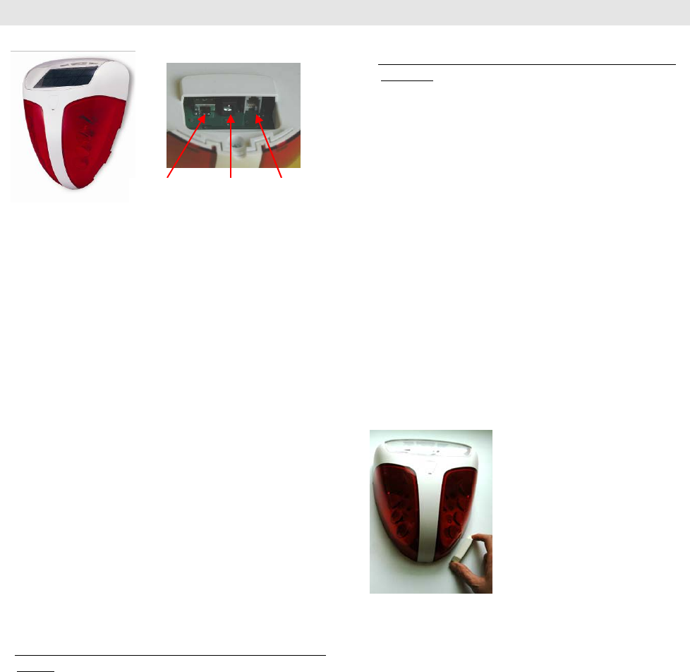
1. turn on the battery switch, refer to Fig 2
2. either connect a 15VDC power adapter (supplied with
LS-30), or connecting the supplied COM1 cable to the
COM1 socket of a LS-30 which is powered, refer to
Fig. 2.
PROGRAMMING
1. Enroll the LS-30 Base Unit ID in the WS-30S, steps as
below,
A). Keep the WS-30S close to the LS-30 Base Unit for
convenient operation. Enter the “Installer Mode” on
the Base Unit and select \Set Siren\ Siren/Relay Test
then wait.
B). Turn on the WS-30S battery switch from off state.
The WS-30S LED would light up
C). Press the “YES” button (for Siren/Relay Test) on
the Base Unit within 30 seconds. The Base Unit would
transmit its RF ID and be enrolled in the WS-30S.
However you can also program this through a PC with
the supplied software.
Important Note: If there is strong light shinning on
the solar panel, it would produce a voltage to the
internal PCB, so that the microprocessor on the PCB
can’t be reset when the battery switch is turned on.
Under such a condition, please turn the solar panel
side down for a few seconds, and then turn on the
battery switch.
2. Enroll the WS-30S ID in the LS-30 Base Unit, steps
as below,
A). Enter the “Installer Mode” on the Base Unit
and select \Set Device\ Enroll Device\ Burglar
Sensor\ Enter Zone No.
B) Use a magnet (not supplied, but you can use the
magnet for TX-3DS Door Sensor) to approach the
right-bottom corner of the WS-30S, refer to Fig. 3.
The WS-30S would emit its RF ID to be enrolled in
the LS-30 Base Unit.
C). The LS-30 LCD would show “Enroll OK” if
action is correct.
Likewise, you can also program this through a PC
with the supplied software.
Remark: When you put a magnet near the
right-bottom corner of the WS-30S, it will generate a
chirp and emit RF signal for test/enrolling. This
action can also be used for RF check, refer to “Master
Mode\ Device Test” of LS-30 manual.
3. If necessary, you can change the alarm time of the
WS-30S by entering the desired time on the LS-30
Base Unit, under \Installer Mode\ Set Timer\ Set
Remote Siren Time.
LOCATION
The WS-30S should be mounted outside the building and
in a position where it can be clearly visible and at a
height (3~5 meters above the ground) that is relatively
difficult for an intruder to access.
The WS-30S is built in radio transmitter and receiver
which can be affected by the presence of metallic objects
in the vicinity. Therefore, please keep the WS-30S
minimum 30 cm away from any metalwork.
Important Note:
It takes 30 hours to fully charge the battery of the
WS-30S under direct sunshine. To provide the maximum
amount of sunlight to the solar panel of WS-30S, it’s
strongly recommended to mount the WS-30S as below:
1).On the wall facing south for the user lives in the
northern hemisphere and above the line of “Tropic of
Cancer” (23.5°North).
2).On the wall facing north for the user lives in the
southern hemisphere and below the line of “Tropic of
Capricorn” (23.5°South).
3).On a wall easterly or westerly for the user can’t find a
suitable location as above or lives in between of the
23.5°North and 23.5°South.
Fi
g.
1
Fi
g.
2
Powe
r
Socket COM1
Socket
Put a magnet closely to the
right-bottom corner to
activate RF transmission.
Fig.3
Battery
Switch

Shadows cast by neighboring walls, trees and roof
overhangs should be avoided. Besides, the sun is lower
in the sky in winter, the winter shadow should be
avoided too where possible.
INSTALLATION AND TEST
1. Remove external power adapter or COM1 cable (if
any) from the WS-30S, and turn off the battery switch.
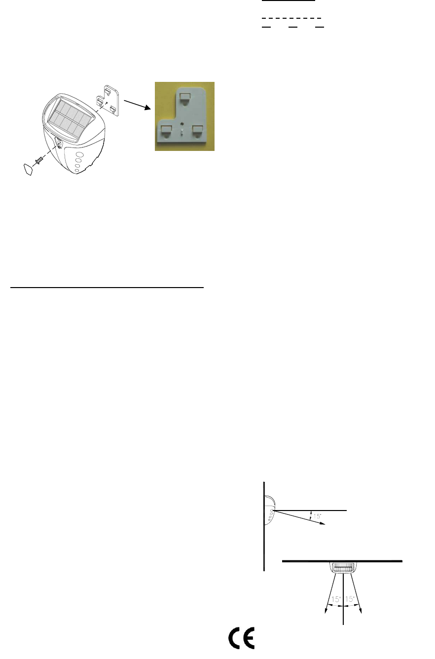
2. Release the mounting bracket from the back side of
the WS-30S by pulling the bracket downward from the
case.
3. Use the mounting bracket as a template, hold it against
the wall where the WS-30S is to be mounted, and
mark the positions of the three screw holes. Drill three
6mm (1/4in.) holes 1 inch deep. Insert the supplied
wall plugs and attach the bracket to the wall with the
screws.
4. Turn on the battery switch. Use the supplied screw
(4mm) to fix the WS-30S on the bracket, refer to Fig 4.
Then put the plastic cap on the cavity of the top cover.
5. It’s a must to test RF range after installation, steps
as below.
A).On the LS-30 Base Unit, entering “Installer Mode”
and select \Set Siren\ Siren/Relay Test then press the
“YES” button, which will trigger the WS-30S to
generate a chirp if everything is correct.
B).Use a magnet to approach the right-bottom corner
of the WS-30S, you will hear a chirp from the WS-30S
and a beep from the LS-30 Base Unit if the distance is
OK.
Remark: If the WS-30S is removed from the bracket,
or the housing is opened, the internal tamper switch
would activate the siren for 5 minutes, or until the
WS-30S is mounted on the bracket again. Meanwhile,
the WS-30S would send a RF signal of tamper
detection to the LS-30 Base Unit.
INDICATION
The reaction of the light and sound of the WS-30S varies
with the operation or alarm state as below,
-Power ON and code enroll: The WS-30S enters
ENROLL state for 30 seconds automatically when the
power is applied. Light stays ON continuously, until the
WS-30S learns a new code (2 chirps), or a 30-second
timeout expires (one chirp, no new code learnt).
-Alarm state: Light flashes, and siren sounds
continuously. When alarm time expires, sound stops but
light keeps flashing until the LS-30 is disarmed by
Master/User press hotkey C (Clear) on the Base Unit.
SOUND TYPES
For the sake of easy identification of the alarm states, the
siren sounds differently with different alarm signals from
the LS-30 Base Unit.
:Burglar Alarm, or WS-30S is
tampered (continuous tone)
:
Fire Alarm
:
Medical Alarm, Panic Alarm, Special
Sensor Alarm, Sensor Tampered
- - :
LS-30 changes from Disarm to Arm
state (two chirps, see Note 2)
- : LS-30 changes from Arm to Disarm
state (single chirp, see Note 2)
Remarks:
1). “-“ means ON, the blank interval means Pause.
2). Assume that “Mode Change Chirp” and “Tamper
Siren” are set “ON” on the Base Unit.
3). Arm/Disarm chirp sound can be disabled by setting
jumper J10 to “Off” with only strobe remains.
LOW BACK-UP BATTERY
Back-up battery is monitored all the time, when low
battery is detected, the WS-30S would send Battery Low
RF signal to the Base Unit. And once the battery is
recharged by sunlight or external power, a “Battery Low
Restore” RF signal will be sent as well.
SPECIFICATIONS:
Power: 1W Solar panel
Internal rechargeable battery: Ni-MH 6V/1200mAH
Fully charged battery back-up time: 30 days
Current consumption: 1.5mA @standby,
170mA @activation
Siren output: about 115 dB (@30cm, facing the piezo
siren)
Strobe: Red or blue as required
Tamper protection: Activates when removing from the
bracket or opening the cover.
RF: 2-way radio.
IP Rating: 54 (with dust and splashing water protected
by proper installation)
Size: 90 x 233 x 190 mm
Weight: 730g
Maximum Strobe Light Viewing Angle
Mounting Bracket
Fig.4
Fig.5
Side view
To
p
view

Manual-BackCover.jpg (2544x3685x16M jpeg)
NOTE: This equipment has been tested and found to comply
with the limits for a Class B digital device, pursuant to part 15 of the
FCC Rules. These limits are designed to provide reasonable
protection against harmful interference in a residential installation.
This equipment generates, uses and can radiate radio frequency
energy and, if not installed and used in accordance with the
instructions, may cause harmful interference to radio communications.
However, there is no guarantee that interference will not occur in a
particular installation. If this equipment does cause harmful
interference to radio or television reception, which can be determined
by turning the equipment off and on, the user is encouraged to try to
correct the interference by one or more of the following measures:
—Reorient or relocate the receiving antenna.
—Increase the separation between the equipment and receiver.
—Connect the equipment into an outlet on a circuit different from
that to which the receiver is connected.
—Consult the dealer or an experienced radio/TV technician for
help.
(c) The provisions of paragraphs (a) and (b) of this section
do not apply to digital devices exempted from the technical
standards under the provisions of § 15.103.
(d) For systems incorporating several digital devices, the
statement shown in paragraph (a) or (b) of this section needs to
be contained only in the instruction manual for the main control
unit.
(e) In cases where the manual is provided only in a form
other than paper, such as on a computer disk or over the Internet,
the information required by this section may be included in the
manual in that alternative form, provided the user can reasonably
be expected to have the capability to access information in that
form.