Scientific Games ITVM01 LOTTERY TICKET TERMINAL User Manual
Scientific Games International LOTTERY TICKET TERMINAL Users Manual
Users Manual

PlayCentral Terminal
(PCT) Technical Manual
Pennsylvania State Lottery
Version 0.5
August 3, 2011
FUNCTIONAL SPECIFICATIONS

SG Documentation Policy
Document Name:
PA - Implementation and Conversion – PCT Technical Manual – V0.5
Date:
August 3, 2011
This document contains information confidential and proprietary to Scientific Games
International, Inc. (SGI), a wholly owned subsidiary of Scientific Games Corporation (SGC)
and may be protected by other forms of intellectual property. The information contained
herein may not be reproduced, paraphrased, translated into another language, or otherwise
disclosed or duplicated by any means without the prior written consent of SGI. Violators
may be prosecuted.
Due to the confidentiality of the subject matter, revisions or alterations are undertaken only
by written agreement with SGI. The information contained in this document is subject to
change by SGI without notice. Distribution of this document or any portion thereof may only
be conducted by SGI or through its designated officials.
The software / systems described in this document are protected by copyright law.
Unauthorized duplication or use of any software described herein is prohibited.
Software features may be described herein which are not implemented in every system.
Similarly, ongoing enhancements to this system may result in the presence of features on a
particular system, which are not included in this edition of the document. Authorized users
will be notified of software / systems modifications through the release of new editions of
this documentation.
SGI MAKES NO WARRANTY, EXPRESSED OR IMPLIED, WITH REGARD TO THIS
MATERIAL, INCLUDING BUT NOT LIMITED TO WARRANTIES OF MERCHANTABILITY
OF FITNESS FOR ANY PARTICULAR PURPOSE. SGI ACCEPTS NO LIABILITY FOR
ERRORS CONTAINED IN THIS DOCUMENT OR FOR INCIDENTAL OR
CONSEQUENTIAL DAMAGES ASSOCIATED WITH ITS PROVISION, CONTENTS, OR
USE.
© 2011 by Scientific Games International, Inc.
All rights reserved.

i Confidential & Proprietary
REVISION RECORD
Version Date Modified By Revisions
0.1 06/2009 Zellers New manual that combined the field service and
bench repair manuals.
0.2 10/2009 Riley Incorporated feedback from SME
0.3 01/2011 Zellers Incorporated feedback from SME
0.4 8/2011 Zellers Incorporated feedback from SME
0.5 8/2011 Zellers Added FCC statement

iii Confidential & Proprietary
PREFACE
Overview of This Manual
This guide describes the maintenance operations for the Pennsylvania Lottery
PlayCentral Terminal (PCT). It provides the technicians with information about performing
the various maintenance operations, and guidelines to follow for troubleshooting and
making decisions.
Chapters in this Manual
This technical manual contains the following chapters:
Section 1 – PlayCentral Terminal (PCT) Overview
Section 2 – Tools and Equipment
Section 3 – Installation Procedures
Section 4 – Quality Control (QC) Testing
Section 5 – Diagnostics
Section 6 – Component Procedures
Section 7 – Troubleshooting
Section 8 – Appendix A
Section 9 – Electronics Tray Test Form
Section 10 – Approvals

Preface PAT Technical Manual
iv Confidential & Proprietary
FCC Statements
FCC Part 15.21
Changes or modifications to an intentional or unintentional radiator herein not expressly
approved by the party responsible for compliance could void the User's authority to operate this
equipment.
FCC Part 15.105
This equipment has been tested and found to comply with the limits for a Class A digital device,
pursuant to part 15 of the FCC Rules. These limits are designed to provide reasonable
protection against harmful interference when the equipment is operated in a commercial
environment. This equipment generates uses and can radiate radio frequency energy and if not
installed and used in accordance with the Instruction Manual, may cause harmful interference to
radio communications. Operation of this equipment in a residential area is likely to cause
harmful interference in which case, the user will be required to correct the interference at their
own expense.

v Confidential & Proprietary
CONTENTS
SECTION 1 PlayCentral TERMINAL (PCT) Overview ....................................... 1-1
1.1Purpose ................................................................................................. 1-1
1.2Components of the PlayCentral Terminal (PCT) ............................... 1-2
1.3System Specifications ......................................................................... 1-3
1.3.1Overall Dimensions ................................................................................... 1-3
1.3.2Electrical Requirements ............................................................................ 1-3
1.3.3Environmental Operating Range ............................................................... 1-3
1.3.4Interface .................................................................................................... 1-4
1.3.5Instant Ticket Acceptance Level ............................................................... 1-4
1.3.6Component Part Numbers ........................................................................ 1-5
1.4PCT Main Unit ....................................................................................... 1-6
1.5Central Processing Unit (CPU) ............................................................ 1-7
1.6Power Supplies ..................................................................................... 1-9
1.6.1Power-Supplied PCT Components ........................................................... 1-9
1.6.2Back-up Power .......................................................................................... 1-9
1.6.3Other Power Requirements ..................................................................... 1-10
1.7Touch Screen Display ........................................................................ 1-10
1.8Bill Acceptor Assembly ..................................................................... 1-11
1.8.1Currency Validator .................................................................................. 1-11
1.8.2Currency Cassette .................................................................................. 1-12
1.9Printer .................................................................................................. 1-13
1.9.1Thermal Printer Paper ............................................................................. 1-13
1.10Ticket Dispenser Assembly ............................................................... 1-14
1.10.1Ticket Pack Storage Area ..................................................................... 1-14
1.10.2Burster Assembly .................................................................................. 1-15
1.10.2.1Stepper Motor ................................................................................ 1-15
1.10.2.2Ticket Leading Edge Sensor .......................................................... 1-15
1.10.2.3Burster Blade ................................................................................. 1-15
1.10.2.4Guide and Drive Rollers ................................................................. 1-15

Contents PAT Technical Manual
vi Confidential & Proprietary
1.10.2.5Deflection Plate .............................................................................. 1-15
1.10.2.6Drive Gearing ................................................................................. 1-15
1.10.2.7Chassis .......................................................................................... 1-16
1.10.3Controller PCB ...................................................................................... 1-16
1.10.3.1Functions........................................................................................ 1-16
1.10.3.2LED Indications .............................................................................. 1-16
1.10.3.3Power Connectors .......................................................................... 1-17
1.10.3.4Operating Conditions ..................................................................... 1-17
1.10.4Enclosure or Upper Cover ..................................................................... 1-17
1.11Barcode (1D/2D) Reader .................................................................... 1-18
1.12Document Scanner ............................................................................. 1-18
1.13Cover Assembly ................................................................................. 1-19
SECTION 2 Tools and Equipment ..................................................................... 2-1
2.1Purpose ................................................................................................. 2-1
SECTION 3 Installation Procedures .................................................................. 3-1
3.1Overview ............................................................................................... 3-1
3.2Accessing the Master Link Operating System .................................. 3-2
3.3Accessing the Aegis Operating System ............................................ 3-2
3.4Diagnostics – Communications_Aegis .............................................. 3-3
3.5Installation Wizard ................................................................................ 3-4
3.6Aegis Bar Code Method ....................................................................... 3-9
3.7Configure PCT Communications ...................................................... 3-11
3.8PCT Installation Checklist ................................................................. 3-13
3.9Pinging Process ................................................................................. 3-14
SECTION 4 Quality Control (QC) Testing ......................................................... 4-1
4.1Overview ............................................................................................... 4-1
4.2Tools and Materials .............................................................................. 4-1

PAT Technical Manual Contents
Confidential & Proprietary vii
4.3Setting up the Terminal ....................................................................... 4-2
4.4Loading Online Paper .......................................................................... 4-3
4.5Loading Instant Tickets ....................................................................... 4-4
4.6Final QC Testing Steps ........................................................................ 4-5
4.7Loopback Testers Illustrated .............................................................. 4-6
SECTION 5 Diagnostics ..................................................................................... 5-1
5.1Overview ............................................................................................... 5-1
5.2Diagnostics Screens ............................................................................ 5-1
5.3Printer Test Screen .............................................................................. 5-2
5.3.1Print Functions .......................................................................................... 5-3
5.3.1.1Print Ticket with Logo ....................................................................... 5-3
5.3.1.2Cut Paper ......................................................................................... 5-4
5.3.1.3Reverse Cut ..................................................................................... 5-4
5.3.2Firmware Controls ..................................................................................... 5-4
5.3.3Update Status ........................................................................................... 5-4
5.4Burster Test Screen ............................................................................. 5-5
5.4.1Burster Tray .............................................................................................. 5-6
5.4.1.1Dispense .......................................................................................... 5-6
5.4.2Test Mode ................................................................................................. 5-6
5.4.3Loop Test .................................................................................................. 5-7
5.4.4Burster Utilities .......................................................................................... 5-7
5.5Scanner Test Screen ............................................................................ 5-8
5.5.1Scanner Diagnostics ................................................................................. 5-9
5.5.1.1Enable Scanner ................................................................................ 5-9
5.5.1.2Eject Forward ................................................................................. 5-10
5.5.1.3Eject Reverse ................................................................................. 5-11
5.5.1.4Brand Ticket ................................................................................... 5-11
5.5.1.5Calibrate ......................................................................................... 5-12
5.5.1.6Toggle Head LEDs ......................................................................... 5-12
5.5.1.7Reset Scanner ............................................................................... 5-13
5.5.1.8Process Saved Image .................................................................... 5-14
5.5.2Scanner Options ..................................................................................... 5-15
5.5.2.1Scanner Output Mode .................................................................... 5-15
5.5.2.2Eject Options .................................................................................. 5-15
5.5.2.3Image Resolution ........................................................................... 5-15
5.5.2.4Software Controls ........................................................................... 5-15

Contents PAT Technical Manual
viii Confidential & Proprietary
5.6Interface Board Screen ...................................................................... 5-16
5.6.1Serial Port Tests ..................................................................................... 5-17
5.6.1.1Serial Port Test .............................................................................. 5-17
5.6.1.2Barcode Reader/Ticket Checker .................................................... 5-18
5.6.1.3Read BCR ...................................................................................... 5-18
5.6.1.4Page BCR ...................................................................................... 5-18
5.6.1.5Set Frequency Address .................................................................. 5-18
5.6.1.6Download FW to BCR .................................................................... 5-18
5.6.1.7Download FW to Printer BCR Controller ........................................ 5-18
5.7Mother Board Screen ......................................................................... 5-19
5.7.1NIC Port .................................................................................................. 5-20
5.7.1.1Start Loop Back Test ...................................................................... 5-20
5.7.2Mother Board Accessories ...................................................................... 5-21
5.7.2.1Calibrate Touch Screen ................................................................. 5-21
5.7.2.2Play Wave File ............................................................................... 5-21
5.8Burn-In Test Screen ........................................................................... 5-22
5.8.1Burn-In Tests .......................................................................................... 5-23
5.8.1.1Print Test Ticket ............................................................................. 5-23
5.8.1.2Paper Cutter ................................................................................... 5-24
5.8.1.3Hard Drive Test .............................................................................. 5-25
5.8.1.4LCD Backlight Toggle .................................................................... 5-26
5.8.1.5Scanner Forward ............................................................................ 5-27
5.8.1.6Toggle Scanner LEDs .................................................................... 5-28
5.9SGI Engine Screen ............................................................................. 5-29
5.9.1General Purpose I/O ............................................................................... 5-30
5.9.1.1Read Inputs .................................................................................... 5-30
5.9.1.2Write Outputs ................................................................................. 5-30
5.9.2Intrusion .................................................................................................. 5-30
5.9.2.1Reset Intrusion Detect .................................................................... 5-30
5.9.3Displays Brightness................................................................................. 5-30
5.10SGI Engine FW Screen ....................................................................... 5-31
5.10.1Platform Version Information ................................................................. 5-32
5.10.2Platform Configuration .......................................................................... 5-32
5.10.3Download to Platform Devices .............................................................. 5-33
5.10.3.1Download Bootloader to Flash ....................................................... 5-33
5.10.3.2Download FW to ATMega48 .......................................................... 5-34
5.10.3.3Download FW to Central ................................................................ 5-34
5.10.3.4Download CPLD code .................................................................... 5-34
5.11Security Board Screen ....................................................................... 5-35
5.11.1Input Sensors ........................................................................................ 5-36
5.11.2Alarm Controls ...................................................................................... 5-36

PAT Technical Manual Contents
Confidential & Proprietary ix
5.11.3Firmware Controls ................................................................................. 5-36
5.12Bill Accepter Screen .......................................................................... 5-37
SECTION 6 Component Procedures ................................................................. 6-1
6.1About this Section ................................................................................ 6-1
6.1.1Document Scanner Calibration ................................................................. 6-1
6.1.2Touch Screen Calibration .......................................................................... 6-2
6.1.3Barcode Reader Configuration .................................................................. 6-2
6.2Barcode Reader Address & Frequency Setup Procedures .............. 6-3
6.2.1Pairing the Wireless Barcode Reader ....................................................... 6-3
6.2.2Replacing the Wireless Barcode Reader (BCR) ....................................... 6-4
6.3Front Advertisement Assembly .......................................................... 6-8
6.3.1Removing the Front Advertisement Lights ................................................ 6-8
6.3.2Removing the Front Advertisement Power Supply .................................... 6-9
6.4Display Assembly ............................................................................... 6-11
6.4.1Removing the Display ............................................................................. 6-11
6.4.2Adding a Second Monitor ........................................................................ 6-15
6.5Electronics Tray ................................................................................. 6-24
6.5.1UPS Power Supply ................................................................................. 6-24
6.5.2PC Power Supply Unit ............................................................................. 6-25
6.5.3Mother Board .......................................................................................... 6-26
6.5.3.1Identifying Mother Board Connections ........................................... 6-26
6.5.3.2Replacing the Mother Board........................................................... 6-27
6.5.4Interconnect Board .................................................................................. 6-30
6.5.4.1Replacing the Interconnect Board .................................................. 6-30
6.5.5Hard Drive ............................................................................................... 6-33
6.5.6Document Scanner Assembly ................................................................. 6-35
6.5.7Clearing a Paper Jam ............................................................................. 6-36
6.5.8Replacing the Assembly Roller ............................................................... 6-37
6.6Instant Ticket Assembly .................................................................... 6-42
6.6.1Loading Instant Tickets ........................................................................... 6-42
6.6.2Replacing the Burster.............................................................................. 6-43
6.6.3Clearing an Instant Ticket Jam ................................................................ 6-45
6.7Printer Assembly ................................................................................ 6-46
6.7.1Replacing the Printer............................................................................... 6-46
6.7.2Loading Printer Paper ............................................................................. 6-48
6.7.3Clearing a Printer Jam ............................................................................ 6-49

Contents PAT Technical Manual
x Confidential & Proprietary
6.8Removing the Currency Cassette ..................................................... 6-50
6.9Printer Ground Rework Process ....................................................... 6-52
6.10Electronics Tray Rework Instructions .............................................. 6-58
6.10.1Modified Connection of the Security Board’s USB Hub to the CPU ...... 6-59
6.10.2Add Ferrite to the Hard Disk Drive 5 Volt Power Line ........................... 6-60
6.10.3Install 1pc USB extension onto Electronic tray ...................................... 6-61
6.10.4Install 2pc USB extension onto Electronic tray ...................................... 6-62
6.10.5Power Harness Rework Instruction ....................................................... 6-64
6.10.6Power Harness installation Instruction .................................................. 6-65
6.10.7Install USB Cable for USB/DVI Card ..................................................... 6-68
6.11CPU Fan Replacement ....................................................................... 6-71
6.12Network Communications ................................................................. 6-73
6.12.1Communications Installations in the Field ............................................. 6-73
6.13Other Communications Setup Procedures ...................................... 6-74
6.13.1CDMA Setup ......................................................................................... 6-74
6.13.2Wireless Setup ...................................................................................... 6-75
SECTION 7 Troubleshooting ............................................................................. 7-1
7.1Overview ............................................................................................... 7-1
7.2Replaceable Parts Management ......................................................... 7-2
7.3Printing Problems ................................................................................ 7-3
7.4Printing Problems ................................................................................ 7-4
7.5Wireless Barcode Reader Problems................................................... 7-5
7.6Charge Coupled Device (CCD) Reader Problems ............................. 7-5
7.7Touch Screen Problems ...................................................................... 7-5
7.8Flat Panel Display Problems ............................................................... 7-6
7.9Other Problems .................................................................................... 7-7
7.10Trouble Codes ...................................................................................... 7-8
7.11Repair Codes ...................................................................................... 7-14

PAT Technical Manual Contents
Confidential & Proprietary xi
SECTION 8 Appendix ......................................................................................... 8-1
Bill of Materials (BOM) ................................................................................... 8-1
PCT Terminal Parts List ................................................................................. 8-1
8.1Schematics ......................................................................................... 8-10
8.1.1Network Schematic ................................................................................. 8-10
8.2Mechanical Drawings ......................................................................... 8-11
8.2.1Paper Roll Specification .......................................................................... 8-11
8.2.2PCT Block Diagram................................................................................. 8-12
8.2.3Interface Board Wiring Diagram .............................................................. 8-13
8.2.4Barcode Reader Initialization Functions .................................................. 8-14
SECTION 9 Electronics Tray Test Form ........................................................... 9-1
9.1Purpose ................................................................................................. 9-1
SECTION 10 Approvals ......................................................................................... 1

xiii Confidential & Proprietary
LIST OF FIGURES
Figure 1: PlayCentral Terminal (PCT) ............................................................................ 1-2
Figure 2: PCT Main Unit ................................................................................................ 1-6
Figure 3: Diagnostics Screen – Communications Aegis ................................................ 3-3
Figure 4: Enter CFE IP address pop-up ......................................................................... 3-4
Figure 5: Enter another CFE IP address pop-up ............................................................ 3-5
Figure 6: Device Group page 1 pop-up .......................................................................... 3-5
Figure 7: Device Group page 2 pop-up .......................................................................... 3-6
Figure 8: Install Successful pop-up ................................................................................ 3-6
Figure 9: Summary Screen ............................................................................................ 3-7
Figure 10: Scan or External Id pop-up ........................................................................... 3-7
Figure 11: Sample External ID ....................................................................................... 3-8
Figure 12: Modify Domain pop-up .................................................................................. 3-8
Figure 13: MAC Install Success pop-up ......................................................................... 3-8
Figure 14: Sample Aegis Install Bar Code ..................................................................... 3-9
Figure 15: Sample Aegis Bar Code ................................................................................ 3-9
Figure 16: Install Success pop-up .................................................................................. 3-9
Figure 17: Sample External ID ..................................................................................... 3-10
Figure 18: MAC Install Success pop-up ....................................................................... 3-10
Figure 19: Windows Task Manager screen .................................................................. 3-14
Figure 20: Create New Task pop-up ............................................................................ 3-14
Figure 21: Task Manager Screen ................................................................................. 3-15
Figure 22: Print Head Release Latch ............................................................................. 4-3
Figure 23: Inserting Instant Tickets into Burster ............................................................. 4-4
Figure 24: Loopback Testers Illustrated ......................................................................... 4-6
Figure 25: Printer Test Screen ....................................................................................... 5-2
Figure 26: Burster Test Screen ...................................................................................... 5-5
Figure 27: Scanner Test Screen .................................................................................... 5-8
Figure 28: Interface Board Screen ............................................................................... 5-16

List of Figures PAT Technical Manual
xiv Confidential & Proprietary
Figure 29: Interface Board Screen ............................................................................... 5-19
Figure 30: Burn-In Test Screen .................................................................................... 5-22
Figure 31: SGI Engine Screen ..................................................................................... 5-29
Figure 32: SGI Engine FW Screen ............................................................................... 5-31
Figure 33: Security Board Screen ................................................................................ 5-35
Figure 34: Bill Accepter Screen .................................................................................... 5-37
Figure 35: Bar Code Reader .......................................................................................... 6-4
Figure 36: Four Screws .................................................................................................. 6-4
Figure 37: New BCR Bracket ......................................................................................... 6-5
Figure 38: New BCR Bracket Screws ............................................................................ 6-5
Figure 39: BCR Cradle ................................................................................................... 6-6
Figure 40: Attaching BCR Cradle ................................................................................... 6-6
Figure 41: Attaching BCR Cradle to Scanner Tray ........................................................ 6-7
Figure 42: Attached BCR Cradle .................................................................................... 6-7
Figure 43: Front Advertisement Assembly – Rear Cover closed .................................... 6-8
Figure 44: Light Panel .................................................................................................... 6-9
Figure 45: Front Advertisement Assembly - Power Supply Cover attached ................. 6-10
Figure 46: Front Advertisement Assembly - Power Supply .......................................... 6-10
Figure 47: Display Assembly - Rear Cover .................................................................. 6-11
Figure 48: Dispenser Tray Light ................................................................................... 6-12
Figure 49: Display Assembly cables ............................................................................ 6-12
Figure 50: Display Assembly - Rear Bracket Attached ................................................ 6-13
Figure 51: Display Assembly - Rear Bracket Attached ................................................ 6-14
Figure 52: Display Assembly - Rear Cover .................................................................. 6-15
Figure 53: Display Assembly - Inside ........................................................................... 6-16
Figure 54: Display Assembly Screws ........................................................................... 6-17
Figure 55: Display Assembly Cables ........................................................................... 6-18
Figure 56: Display Connection ..................................................................................... 6-19
Figure 57: DVI Card ..................................................................................................... 6-20
Figure 58: Power Connector ........................................................................................ 6-21
Figure 59: DC Supply Cable ........................................................................................ 6-22
Figure 60: USB Cable Connection ............................................................................... 6-23

PAT Technical Manual List of Figures
Confidential & Proprietary xv
Figure 61: UPS Power Supply ..................................................................................... 6-24
Figure 62: PC Power Supply ........................................................................................ 6-25
Figure 63: Mother Board .............................................................................................. 6-26
Figure 64: Black Key Inserted ...................................................................................... 6-27
Figure 65: Removing the Electronics Tray ................................................................... 6-28
Figure 66: Removing the Mother Board from the Electronics Tray .............................. 6-28
Figure 67: Re-inserting the Electronics Tray ................................................................ 6-29
Figure 68: Black Key Inserted ...................................................................................... 6-31
Figure 69: Removing the Electronics Tray ................................................................... 6-31
Figure 70: Hard Drive ................................................................................................... 6-33
Figure 71: Hard Drive Thumbscrews ........................................................................... 6-34
Figure 72: Document Scanner Cable ........................................................................... 6-35
Figure 73: Document Scanner – Open ........................................................................ 6-36
Figure 74: Assembly Roller and Bracket ...................................................................... 6-37
Figure 75: Assembly Roller Bearings ........................................................................... 6-37
Figure 76: Assembly Roller Bearings ........................................................................... 6-38
Figure 77: Assembly Roller Bearings ........................................................................... 6-38
Figure 78: Assembly Roller Shaft and Spring .............................................................. 6-39
Figure 79: Assembly Roller Washer ............................................................................. 6-39
Figure 80: Assembly Black Plastic Roller and Screws ................................................. 6-40
Figure 81: Assembly Swing Arm .................................................................................. 6-40
Figure 82: Printer Roller Bracket .................................................................................. 6-41
Figure 83: Burster Wire Protective Cover screw .......................................................... 6-43
Figure 84: Burster Assembly Wires .............................................................................. 6-44
Figure 85: Burster Assembly Hex Nuts ........................................................................ 6-44
Figure 86: Reverse Button on Burster .......................................................................... 6-45
Figure 87: Print Head Release Latch ........................................................................... 6-46
Figure 88: Printer Thumbscrew .................................................................................... 6-47
Figure 89: Print Head Release Latch ........................................................................... 6-48
Figure 90: Print Head Release Latch ........................................................................... 6-49
Figure 91: Bill Enclosure Cabinet ................................................................................. 6-50
Figure 92: Print Head Release Latch ........................................................................... 6-50

List of Figures PAT Technical Manual
xvi Confidential & Proprietary
Figure 93: Currency Cassette Key ............................................................................... 6-51
Figure 94: Reinsert Currency Cassette ........................................................................ 6-51
Figure 95: Routing the Exposed Printer Cable through the Blue Cable Clamp ............ 6-52
Figure 96: The Closed Clamp on Cable ....................................................................... 6-52
Figure 97: Connecting Printer Grounds to the Terminal’s Cabinet Wall ....................... 6-53
Figure 98: Grounding the Printer Chassis During Rework ........................................... 6-54
Figure 99: Accessing Printer Screw ............................................................................. 6-55
Figure 100: Template for Position of the Hole Drilled in the Printer’s Sidewall............. 6-56
Figure 101: Printer Ground Wire, Viewed from the Bottom of the Printer .................... 6-56
Figure 102: Modified Printer Grounding Complete ....................................................... 6-57
Figure 103: Unplug 12V Power .................................................................................... 6-58
Figure 104: Removing old 60 Pin Cable ...................................................................... 6-59
Figure 105: Connecting the new 60 Pin Cable to the Motherboard .............................. 6-59
Figure 106: Ferrite Attached to the Disk Drive’s 5 Volt Power Line .............................. 6-60
Figure 107: Plug in the USB Connector ....................................................................... 6-61
Figure 108: USB Connectors ....................................................................................... 6-62
Figure 109: Attaching the New USB Extension Cable to the Electronics Tray ............. 6-62
Figure 110: Routing the USB Cable Pass the Motherboard ......................................... 6-63
Figure 111: Plug in the USB Connector ....................................................................... 6-63
Figure 112: Power Harness Removal .......................................................................... 6-64
Figure 113: AC/DC connector removal ........................................................................ 6-64
Figure 114: Power Harness Install (Inside) .................................................................. 6-65
Figure 115: Power Harness AC/DC Connector Install ................................................. 6-66
Figure 116: Ground Cable Install ................................................................................. 6-67
Figure 117: Cable Dressing ......................................................................................... 6-68
Figure 118: Cable Dressing Continued ........................................................................ 6-69
Figure 119: Cable Dressing Along Main Harness ........................................................ 6-70
Figure 120: Fan and Heat Sink .................................................................................... 6-71
Figure 121: Dual Ball Bearing Fan ............................................................................... 6-71
Figure 122: Dual Ball Bearing Fan Indication ............................................................... 6-72
Figure 123: CDMA Communication Setup ................................................................... 6-74
Figure 124: Wireless Communication Setup ................................................................ 6-75

PAT Technical Manual List of Figures
Confidential & Proprietary xvii
Figure 125: Network Schematic ................................................................................... 8-10
Figure 126: Printer Paper Roll Dimensions and Tolerances ........................................ 8-11
Figure 127: PCT Block Diagram .................................................................................. 8-12
Figure 128: PCT Interface Board Wiring Diagram ........................................................ 8-13
Figure 129: Sample Barcode - Enable Parameter Scanning ....................................... 8-14
Figure 130: Sample Barcode - Set All Defaults ............................................................ 8-14
Figure 131: Sample Barcode - 12 of 5 – Any Length ................................................... 8-14
Figure 132: Sample Barcode - Data/Suffix ................................................................... 8-15
Figure 133: Sample Barcode - Disable Parameter Scanning ....................................... 8-15

1-1 Confidential & Proprietary
SECTION 1
PLAYCENTRAL TERMINAL (PCT) OVERVIEW
1.1 Purpose
It is assumed that the reader has a good working knowledge of standard personal
computer hardware and some experience repairing computer terminals.
The PCT comprises the following major assemblies:
• Central Processing Unit (CPU)
• Power Supplies
• Touch Screen Display
• Bill Acceptor Assembly
• Printer
• Ticket Dispenser Assembly
• Barcode Reader
• Document Scanner
• Cover Assembly
Introduction PAT Technical Manual
1-2 Confidential & Proprietary
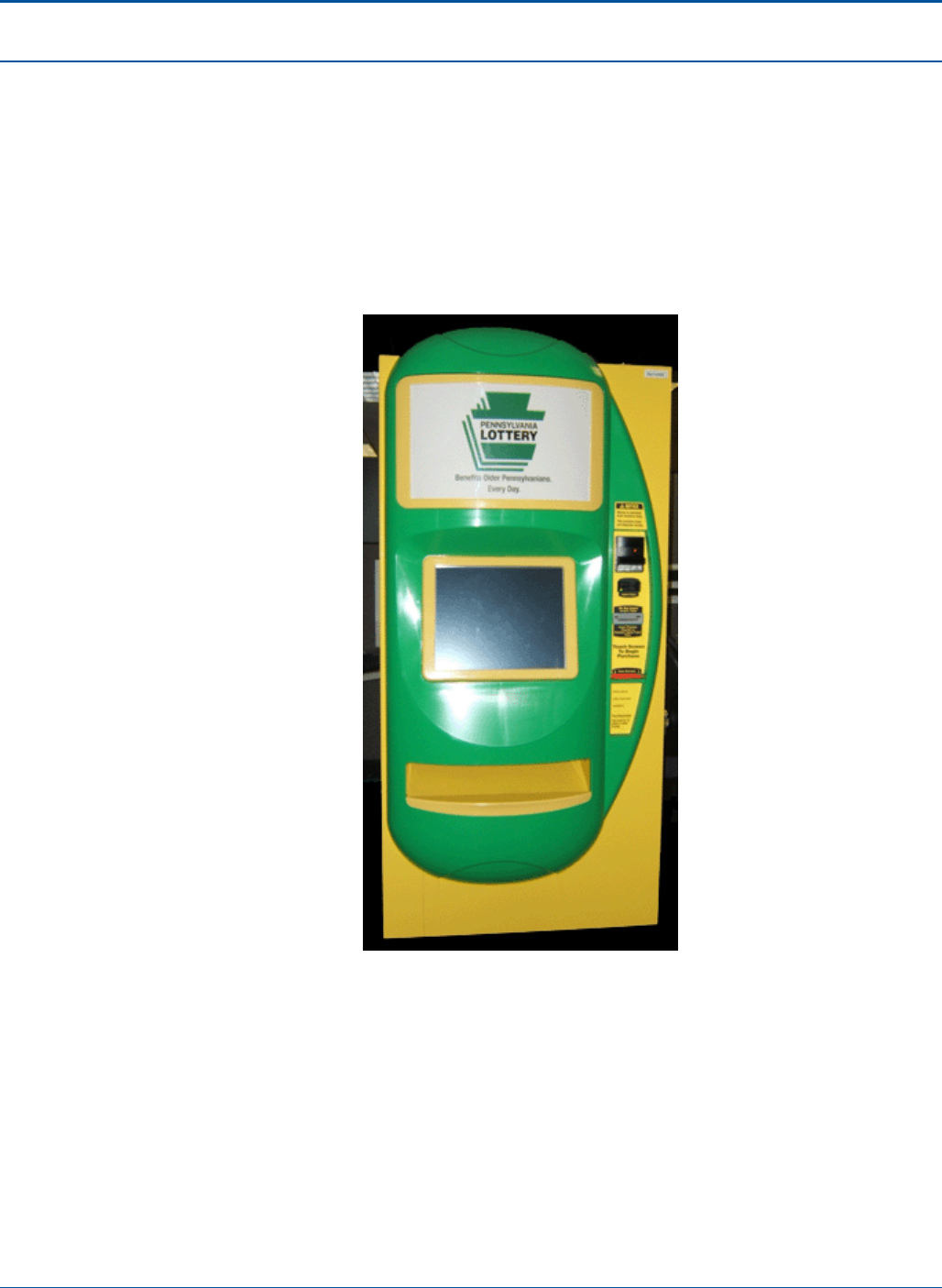
1.2 Components of the PlayCentral Terminal (PCT)
PlayCentral Terminal (PCT) is an automated on-line and instant ticket terminal used to
advertise, sell, and dispense lottery tickets. Each terminal can be connected to a central
computer system via a site-specific Wide Area Network (WAN) system. Components of
the terminal are housed in a sturdy compact unit for convenient installation. A color liquid-
crystal display (LCD) and touch screen interface offer the operator fast and easy access
to a variety of transactions, such as placing wagers and validating tickets.
Figure 1: PlayCentral Terminal (PCT)

PAT Technical Manual Introduction
Confidential & Proprietary 1-3
1.3 System Specifications
The following tables contain the specifications for PCT terminal. These items must be
consistent with those in the global list of terms and acronyms.
1.3.1 Overall Dimensions
Dimension Size
Height 72 inches
Width 35 inches
Depth 28 inches
Weight 570 pounds
Table 1: PCT Overall Dimensions
1.3.2 Electrical Requirements
Category Value
Volt Range 90-260 VAC
Frequency Range 47-63 Hz
Current 3.0 A max (0.5 A average)
Table 2: PCT Electrical Requirements
1.3.3 Environmental Operating Range
Category Value
Operating Temperature 0°C to 45°C (32°C to 113°F)
Transportation Temperature -10°C to 60°C (-14°C to 140°F)
Operating Humidity 5% to 98% non-condensing
Table 3: PCT Environmental Operating Range

Introduction PAT Technical Manual
1-4 Confidential & Proprietary
1.3.4 Interface
Category Value
Serial Ports 2
Ethernet 1 10/100
USB 5
Cash Drawer 1
PCI 2 slots
Audio 2 Audio Out and 1 Audio In
Power outlet for the customer display 90-265 VAC
Keyboard/Key Pad USB
Mouse (Disabled by Operating System) USB
Table 4: PCT Interface
1.3.5 Instant Ticket Acceptance Level
Media Low Range High Range
Instant ticket pack width 1.4 inches 4.00 inches
Instant ticket length 2.0 inches 12 inches
Paper thickness 8 point 12 point
Table 5: PCT Environmental Operating Range

PAT Technical Manual Introduction
Confidential & Proprietary 1-5
1.3.6 Component Part Numbers
Category Part Number
Display - Clerk SA15-0391
Electric Drawer SA05-0151
Power Supply – 24V/2A max PS60-0020
Power Supply – 12VDC PS90-0008
Engine Board PA50-0026-01
Hard Drive DV660-0017
Cooling Fan SA90-0362
Display – 4.7 with touch Kyocera SA15-0377
Burster Tray SA05-0152
ITVM Light Box SA10-0349
Display – 19 inch SA15-0390
Printer SA25-0017
Bar Code Reader SA30-0045-02
Scanner – 4 inch SA30-0047-02
Scanner – 4 inch (External?) SA30-0026-05
ITVM Tilt Switch SA90-0031-01
Table 6: PCT Component Part Numbers
Introduction PAT Technical Manual
1-6 Confidential & Proprietary
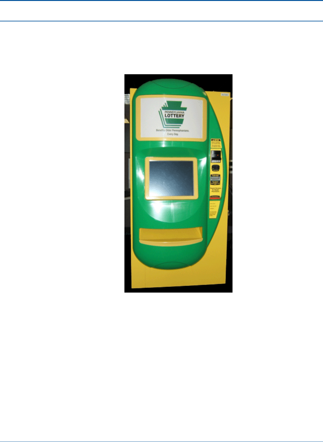
1.4 PCT Main Unit
The PlayCentral Terminal (PCT) Main Unit consists of the clerk display (SA15-0391), 4-
inch scanner (SA30-0047-02), burster tray (SA05-0152), and 19 inch display (SA15-
0390).
Figure 2: PCT Main Unit

PAT Technical Manual Introduction
Confidential & Proprietary 1-7
1.5 Central Processing Unit (CPU)
The Central Processing Unit (CPU) provides all the necessary control functions for the
PCT via:
• Operating system
• On-line and instant games application software
• Hardware controls
Other than player input, the only other input to the PCT is via a communication
connection to the PA Host System.
Description Specification
System Board PCT uses a standard Windows/Intel (“Wintel”) System
PCB system board. It contains, or is directly linked to,
the following:
• Microprocessor running at 1.5 GHz
• Random Access Memory (RAM)
• Hard Disk Drive (HDD)
• Video AGP PCB
• Modem PCB
• Sound PCB
• Interface PCI PCB
CPU Intel® Celeron® M processor 1.5 GHz
Cache 512KByte 2nd Level
Motherboard Intel 82855GME, 400MHz FSB
Sound Integrated AC97 controller
LAN Integrated 10/100Mbits, Intel 82562EM Ethernet
controller
Memory DDR RAM 512MB SO-DIMM, PC1600/2100
NVRAM 0
SO-DIMM sockets 1, none available
Graphics Card Integrated Intel Extreme Graphics II (dual head)
Hard Disk 2.5-inch format with 40GB
Cooling CPU-fan - high quality with ball bearings and heat
spreader plate
Power Supply Fan
Operating System Windows XP Embedded

Introduction PAT Technical Manual
1-8 Confidential & Proprietary
Description Specification
Ticket Dispenser Assembly
Interface PCT uses an Interface PCB to control commands sent
between the CPU and up to sixteen (16) Bursting
Assemblies.
Printer Interface CPU includes an interface to the Printer.
Touch Screen Interface CPU includes an interface to the Touch Screen
Display.
Currency Validator Interface CPU includes an interface to the Currency Validator.
Internal Interfaces PCT also includes such interfaces that are necessary
to route signals between the CPU and any other
terminal peripherals not identified in this table. These
interfaces also route all power between the CPU and
these units.
External Communications Communications capability includes:
• Local/Wide Area Network (LAN/WAN)
• Broadband or wireless-based systems
NOTE: Satellite communications requires an Ethernet
connection (RJ45).
RRS Interface PCT includes an interface with RRS via RS232 serial
interface.
Future interface may include and not limited to wireless
serial interface.
Table 7: Central Processing Unit (CPU)

PAT Technical Manual Introduction
Confidential & Proprietary 1-9
1.6 Power Supplies
The PCT derives all necessary power from a single 110 V input AC line.
Additional outlets can be installed inside the PAT. All PCT power supplies shall be UL
and FCC approved.
1.6.1 Power-Supplied PCT Components
The PCT includes all necessary internal Power Supply Unit(s), which provide necessary
voltages, amperages, and wattages to supply:
• CPU (and its associated disk drives and PCBs)
• Bill Acceptor assembly
• Touch Screen
• 1-D Barcode Reader
• Document Scanner
• Printer Module (including the Cutter Unit)
• Security and signage systems
1.6.2 Back-up Power
The PCT employs a Commercial, Off-The-Shelf (COTS) Uninterruptible Power Supply
(UPS) to provide sufficient backup power automatically, in the event of a loss of power to
the terminal, to:
• Allow any current ticket transaction to be completed.
• Allow the CPU to shut down normally.
• Power the power Failure Alarm.
• Power the unauthorized Intrusion System sensors.
• If activated, power the Unauthorized Intrusion Alarm.
NOTE: The UPS can provide power for 15-35 minutes. If the power outage is estimated
to last longer, the terminal will need to be shut down to prolong the life of the UPS.

Introduction PAT Technical Manual
1-10 Confidential & Proprietary
1.6.3 Other Power Requirements
Additionally, with regard to power supplies, the PCT is required to:
• Meet or exceed industry standards with regard to Electromagnetic Interference
(EMI).
• Contain an internal surge protector that meets or exceeds industry standards for
computer related products.
1.7 Touch Screen Display
The Touch Screen Display is a full-color, graphic, backlit, LCD display.
Description Specification
Minimum Resolution 1280 pixels wide x 1024 pixels high
Viewing Area (approximate) 11.75" x 15.4" (29.84cm x 39.12cm)
Dot Size 13 thousandths of an inch
Dot Pitch 12 thousandths of an inch
Colors 262,000 different colors (minimum)
Table 8: Touch Screen Display Specifications
The Touch Screen Display allows the player to purchase on-line and instant game
tickets. The layout of the “touch buttons” on the screen is customizable and controlled by
the application software. Appropriate areas of the game screens react when a player
touches that area of the screen, initiating actions pre-programmed into the PCT software.

PAT Technical Manual Introduction
Confidential & Proprietary 1-11
1.8 Bill Acceptor Assembly
The Bill Acceptor assembly facilitates currency validation and bill collection, storage, and
removal. It is comprised of two components:
• Currency Validator
• Currency Cassette
The Currency Validator and Currency Cassette are physically connected and
electronically interlocked.
1.8.1 Currency Validator
The Currency Validator scans each bill inserted into the PAT. It will be programmable to
accept any bills authorized for acceptance by the Pennsylvania Lottery. However, at a
minimum, the Currency Validator accepts any or all of the following U.S. currency:
• $1
• $5
• $10
• $20
NOTE: The PCT does not accept $2 bills.
If a bill of an acceptable denomination is inserted, the Currency Validator scans the bill to
determine its authenticity. If the bill is authentic, the Currency Validator then:
• Passes the bill on to the Currency Cassette
• Credits the value of the bill to the current play session
NOTE: The bill may be inserted either face up, face down, face forward, or face
backward.
If the bill is unacceptable (unreadable, counterfeit, foreign, unacceptable denomination),
the Currency Validator returns that bill to the player.
The Currency Validator includes an interface to pass the validation and denomination
information to the CPU.

Introduction PAT Technical Manual
1-12 Confidential & Proprietary
1.8.2 Currency Cassette
The Currency Cassette is the repository for all accepted bills. The Bill Acceptor can
accommodate Currency Cassettes that retain as many as 1000 bills.
The Currency Cassette is removable as a sealed unit. It must be removed from the Bill
Acceptor assembly in order to remove any stored bills.
To minimize loss from theft, the cassette is locked using:
• One standard internal lock
• Optionally, hardware necessary to attach a padlock, of sufficient size to protect the
contents of the cassette, between the cassette and the PCT chassis
NOTE: When the Currency Cassette is removed, the PCT will not accept bills. (However,
no error message will display on the touch screen.)

PAT Technical Manual Introduction
Confidential & Proprietary 1-13
1.9 Printer
The PCT printer is a serial printer and provides high-speed and on-line ticket printing. It
has a self-adjustable ticket cutting mechanism, integrated into a single Field Replaceable
Unit (FRU).
The printer uses a thermal roll paper stock of the following specifications:
3.25" (8.255 cm) wide
• Maximum paper roll diameter of 7.00" (17.78 cm).
• The print head resolution is 200 dpi.
Access for loading the paper into the print head is by feeding the paper into the rear of
the print head.
1.9.1 Thermal Printer Paper
Characteristics Specification
Paper Width 3 ¼ inches
Roll Core Diameter 1 ½ inches
Roll Size 5 3/8 inches
Basis Weight (lbs./rm 17 ins. X 22 ins
– 500) (gm./sq. meter) 23.5 + 1/1 88.3 + 3.3
Caliper (inches) Target: 0.0039 Range: 0.0037 – 0.0042
Tear (Elmendorf) MD (gm)
CD (gm)
60 Nominal
70 Nominal
Stiffness (Gurley) MD (mg)
CD (mg)
170 Nominal
60 Nominal
Sheffield Smoothness 50 Maximum
Image density on Atlantek 300 (12.0
volts)
(MacBeth Densitometer)
1.25 – 1.38
Background (Colortouch with UV, 8
sheets) 90.0 average
Table 9: Thermal Printer Paper Characteristics

Introduction PAT Technical Manual
1-14 Confidential & Proprietary
1.10 Ticket Dispenser Assembly
Four ticket dispenser assemblies exist in one drawer within the PCT with a maximum of
24 ticket dispenser assemblies (or six drawers). Each Ticket Dispenser Assembly is
comprised of the following components:
• Ticket Pack Storage Area
• Burster Assembly
• Controller PCB
• Wiring Harness
• Enclosure or Upper Cover
1.10.1 Ticket Pack Storage Area
A Ticket Pack Storage Area is capable of accommodating instant ticket packs of the
following dimensions (in inches):
• Minimum 2.00L x 1.40W x 0.50H
• Maximum 12.00L x 4.00W x 3.00H
Each Storage Area can hold a maximum 1,500 standard (2-inch) instant tickets.

PAT Technical Manual Introduction
Confidential & Proprietary 1-15
1.10.2 Burster Assembly
The Bursting Assembly is capable of accommodating all instant ticket sizes of the
following dimensions (in inches):
• Minimum 4.00W x 2.00L
• Maximum 4.00W x 12.00L
The Burster Assembly detaches one ticket from another by using seven different
components.
1.10.2.1 Stepper Motor
The Stepper Motor provides a means of controlling the position of the ticket in the
Bursting Assembly. It has the following capabilities:
• Both forward and backward movement
• Exerting a torque sufficient to burst all of the candidate tickets
1.10.2.2 Ticket Leading Edge Sensor
The Ticket Leading Edge Sensor senses the leading edge of each ticket as it exits the
Bursting Assembly Drive Roller. It is positioned in the center of the paper path and in a
location to accurately position the leading edge of the ticket.
1.10.2.3 Burster Blade
The Burster Blade separates one ticket from another without damaging either ticket.
1.10.2.4 Guide and Drive Rollers
The Guide and Drive Rollers provide guidance for tickets exiting the terminal without
damaging either the ticket surface or the scratch off masking material.
1.10.2.5 Deflection Plate
The Deflection Plate redirects the ticket downwards to weaken the perforations between
the tickets prior to bursting and to position the perforation for bursting. It is controlled, via
the Drive Gearing, by the Stepper Motor.
1.10.2.6 Drive Gearing
The Drive Gearing transmits angular forces from the Stepper Motor to the Guide Rollers
and the Deflection Plate. It includes a cam mechanism for controlling the Deflection Plate.

Introduction PAT Technical Manual
1-16 Confidential & Proprietary
1.10.2.7 Chassis
The Chassis is made from injection-molded plastic. It contains all the components of the
Bursting Assembly.
In addition, it includes the following fasteners:
• Mounting the Controller PCB without the need for alignment procedures
• Attaching the Chassis to the Dispenser Unit Mounting Frame without the need for
alignment procedures
1.10.3 Controller PCB
The Controller PCB provides an interface between the Bursting Assembly and the
Interface PCB in the CPU. It employs a proprietary SGI developed protocol for controlling
the Bursting Assembly Stepper Motor and providing sensor and motor position data, via
the Interface PCB, to the CPU.
Power Supplies
The following power supplies are provided for the Controller PCB:
• 24 volt @ 6 Amps
• 5 volt @ 8 Amps
1.10.3.1 Functions
The Controller PCB provides the following functions for controlling the issuance of instant
tickets:
• Stepper Motor control (both forward and reverse)
• Ticket insertion sensing
• Ticket Leading Edge sensing
• Jammed ticket detection
• PCB Power conditioning (if necessary)
1.10.3.2 LED Indications
The Controller PCB can include any or all of the following indications:
• Dispenser Assembly Active/Healthy
• Dispenser Assembly Fault
• Dispenser Empty
• Ticket Jam

PAT Technical Manual Introduction
Confidential & Proprietary 1-17
A single Light Emitting Diode (LED) is used to indicate these situations:
• Steady Power ON - Dispenser Assembly functioning normally
• Slow Flash Dispenser Assembly empty
• Rapid Flash Dispenser Assembly jammed or failed
1.10.3.3 Power Connectors
The Controller PCB can have separate connectors for power (20VDC, 5VDC, and
Ground) and data.
1.10.3.4 Operating Conditions
All components used in the design of the Controller PCB are capable of operating under
the following conditions:
• Temperature
• Minimum 5°C (40°F)
• Maximum 40°C (104°F)
• Humidity (non-condensing)
• Minimum 10.0%
• Maximum 90.0%
1.10.4 Enclosure or Upper Cover
The Enclosure or Upper Cover protects the Controller PCB from damage and debris
intrusion.

Introduction PAT Technical Manual
1-18 Confidential & Proprietary
1.11 Barcode (1D/2D) Reader
The PCT includes a 1D/2D Barcode Reader for scanning ticket packs to load into the
bursters and pre-validation of on-line tickets.
1.12 Document Scanner
The scanner assembly is a Contact Image Sensor operating at 200 DPI. The scanner is
used to read or validate play slips, terminal vouchers, and on-line tickets. The scanner
reads the document and then transmits the information to the application software for
processing. Reading occurs at 18 inches per second.
The scanner assembly also incorporates a brander. This mechanism allows for printing
only on winning thermal tickets via a 24 MM wide thermal print head. The minimum
document length is 2.5 inches. The brander is located on the right side of the scanner.
NOTE: The PCT retains all winning tickets up to a pre-determined limit and returns all
non-winning tickets to the player.

PAT Technical Manual Introduction
Confidential & Proprietary 1-19
1.13 Cover Assembly
The PCT Cover assembly is comprised of two sub-assemblies:
• Front Door
• Cabinet
The PCT Cover assembly meets the following specifications:
• Cabinet is a three-sided, single-piece structure constructed from 14-gauge steel
with reinforced, overlapping seams, with an integral top and bottom.
• Front Door shall be hinged to the Cabinet, using internal hinges.
• Designed to meet all appropriate safety and ergonomic standards. It has no
square corners or sharp edges to injure the players, retailers, or maintenance
personnel.
• Sufficiently weighted to:
• Prevent PCT from tipping over with or without the Front Door open and all
the Dispenser Assembly Racks extended.
• Deter theft.
• Includes sufficient space to accommodate:
• Up to 24 Instant Ticket Dispensing Assemblies on six extendable, four berth
Dispenser Unit Mounting Frames.
• Following items, mounted below the Ticket Dispensing Assembly frames,
on an extendable shelf:
• Central Processor Unit (CPU)
• Power Supply Unit
• Printer Assembly
• Currency Validator (CV).
• Removable Currency Cassette.
• 1D/2D Barcode Reader.
• 3.25-inch Document Scanner.
• All interconnecting wiring and wire harness ducting.
NOTE: Wiring harness allows for the extension of all the frames and the shelf
simultaneously.
• Sufficient space to accommodate the following optional items of equipment, which
may be installed at a later date:
• Combination SmartCard/MagCard Reader.

Introduction PAT Technical Manual
1-20 Confidential & Proprietary
• Mechanical locks, intrusion sensors, and audible alarms are included to maximize
security.
• Front Door is secured to the Cabinet with four (4) locking points, with tamper-proof
and hardened, cut-proof pins on all four locking devices.
NOTE: These locking points differ from the key locks that provide access to the
PCT internal mechanisms and functions.
• Primary Lock is a two-position model with electrical connections.
• Turning the key in the opposite direction from center shall disable the intrusion
alarm system and open the kiosk front door.
• Turning the key to the central position shall lock the front door and enable the
intrusion alarm system.
• Key can be removed only in the locked position.
• Intrusion alarm system operates at all times, even if main power is removed from the
PAT.
• Includes all wiring necessary to interconnect the components of the ticket dispensing
system.
• All wiring is bundled into harnesses. All portions of these harnesses that are
accessible to the retailer are secured in quick-release conduits.
• All wiring harnesses and connectors are marked clearly and logically for identification.
• Includes side-mounted handles to allow easy transportation and handling.
• Provision for transportation using a Fork-Lift vehicle can be included in the chassis.
• Designed for easy access for servicing, ticket loading, and paper changing.

2-1 Confidential & Proprietary
SECTION 2
TOOLS AND EQUIPMENT
2.1 Purpose
The following list identifies the tools and equipment (required and recommended) that
you should maintain in your personal inventory for bench repair on a terminal.
Tools and Equipment
Type Tool/Equipment
Hand Tools
Screwdriver
• Flathead
• Philips #1
• Philips #2
• Jewelers
• Magnetic
Pliers (needlenose)
Wrench
• Allen
• 1/16 inch
Wire cutters / strippers
Driver
• Nut driver
• 5/16 inch
Electronic
Multimeter
Loopback plugs (for communications testing)
Cleaning Kit (optional)
Isopropyl alcohol
Cloths (lint-free)
Glass Cleaner (alcohol-free)
Plastic Cleaner

Overview WAVE™ Terminal Software Functional Specification
2-2 Confidential & Proprietary
Tools and Equipment
Type Tool/Equipment
Miscellaneous
USB Memory Stick (min 1Gb)
Knife (sharp)
Vacuum Cleaner (anti-static, with attachments)
Flashlight (small)
Loctite to prevent screws from vibrating
Pencil (with eraser)
Plain 8 ½ X 4 inch white paper
Table 10: Bench Repair Tools and Equipment

3-1 Confidential & Proprietary
SECTION 3
INSTALLATION PROCEDURES
3.1 Overview
The following procedures are required in order to install the PCT terminal and its
peripherals:
• Accessing the Master Link operating system
• Accessing the Aegis operating system
• Diagnostics – Communications_Aegis
• Installation Wizard
• Aegis Bar Code Method
• Configure PCT Communications
• Pinging Process

Installation Procedures PAT Technical Manual
3-2 Confidential & Proprietary
3.2 Accessing the Master Link Operating System
Prior to performing the PCT configuration, the installer must verify and record all
information off the old PCT terminal. This is required to ensure that the new terminal is
configured the same as the old terminal.
To access this information, you will need to power up the old PCT and access the tech
diagnostic. Next you have to enter the communications configuration screen and record
the information listed in the top of the display.
3.3 Accessing the Aegis Operating System
NOTE: The terminal will boot-up into the Master Link operating system.
The steps below will guide you through the process of entering the Aegis operating
system for the communication configuration procedure:
1. Power on the terminal:
a. UPS on/off switch
b. Terminal on/off switch
2. Connect the USB keyboard to the USB ports located on the underside of the
electronic drawer.
3. Press [F9] on the keyboard. This will close out the Master Link application and
open the windows desk top.
4. Locate and select the icon labeled “Phase2”. This will launch the Aegis
software
PAT Technical Manual Installation Procedures
Confidential & Proprietary 3-3
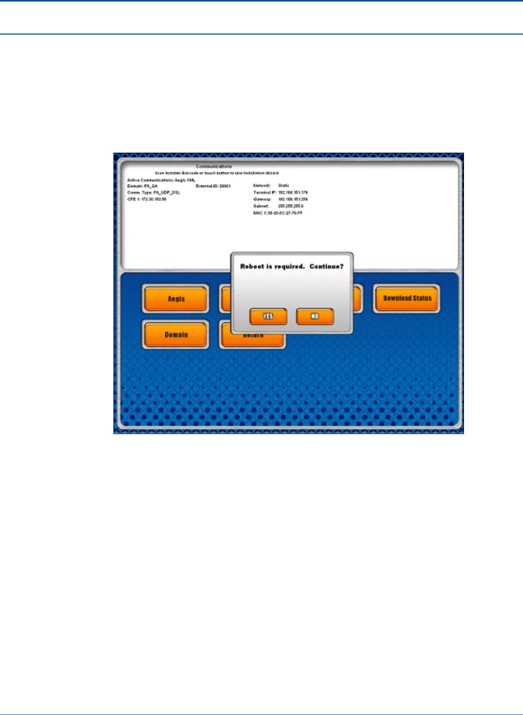
3.4 Diagnostics – Communications_Aegis
Boot the terminal and touch “Diagnostics”. Touch “Tech Signon” and sign in as a Field
Engineer. Touch “Comm Diags”. Touch the “Aegis” button. Note that if “MasterLink” is the
“Active Communications”, then touching “Aegis” will display a prompt indicating that the
Terminal will need to be rebooted.
Figure 3: Diagnostics Screen – Communications Aegis
Installation Procedures PAT Technical Manual
3-4 Confidential & Proprietary
3.5 Installation Wizard
Once the terminal completes the reboot, repeat the steps in the Accessing the Master
Link Operating System section. After touching the “Aegis” button, answer the following
prompts as the Installation Wizard guides you through installation:
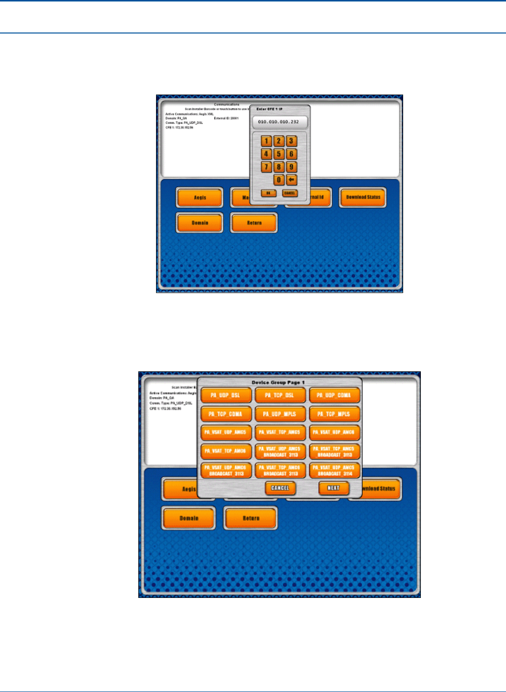
1. Enter the CFE IP address and touch [OK].
Figure 4: Enter CFE IP address pop-up
PAT Technical Manual Installation Procedures
Confidential & Proprietary 3-5
2. Touch [Yes] and repeat the previous step until all CFE IP addresses have been
entered. When all CFEs have been entered, touch [No].
NOTE: Up to 12 CFE IP addresses can be entered.
Figure 5: Enter another CFE IP address pop-up
3. Touch the Device Group that is the correct communications type for your retailer. If
you do not see the correct device group, touch [NEXT] to display the second page
of Device Groups.
Figure 6: Device Group page 1 pop-up
Installation Procedures PAT Technical Manual
3-6 Confidential & Proprietary
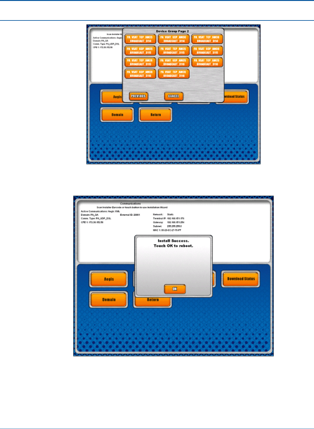
Figure 7: Device Group page 2 pop-up
4. If the Installation is successful, the Install Successful pop-up displays.
Figure 8: Install Successful pop-up
5. To use the new installation parameters, press [OK] to reboot the terminal.
PAT Technical Manual Installation Procedures
Confidential & Proprietary 3-7
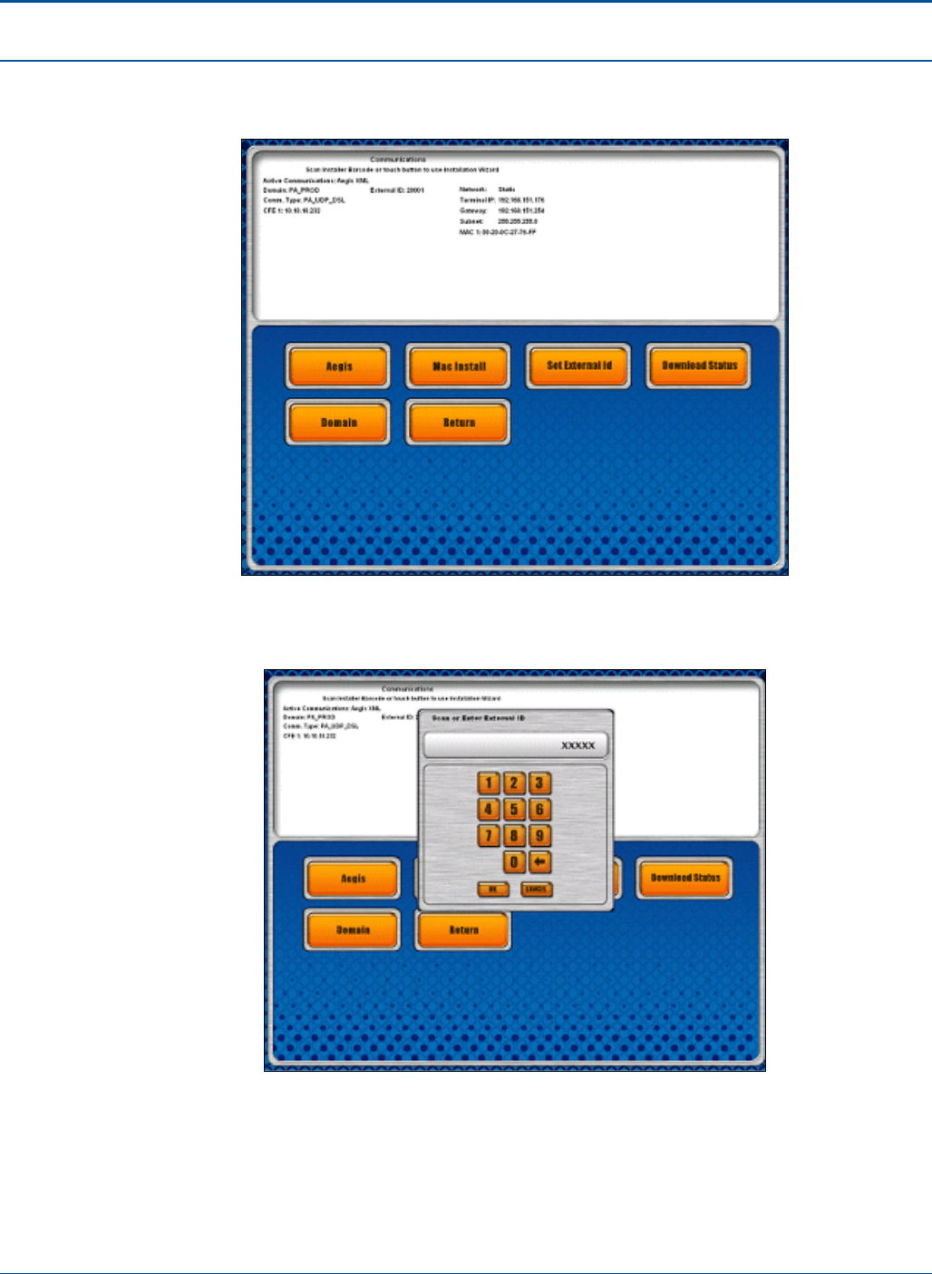
6. When the installation succeeds, the Summary Screen shows the DLS IP
addresses and ports that were installed.
Figure 9: Summary Screen
7. Touch [Set External Id] to display the following pop-up.
Figure 10: Scan or External Id pop-up
Installation Procedures PAT Technical Manual
3-8 Confidential & Proprietary
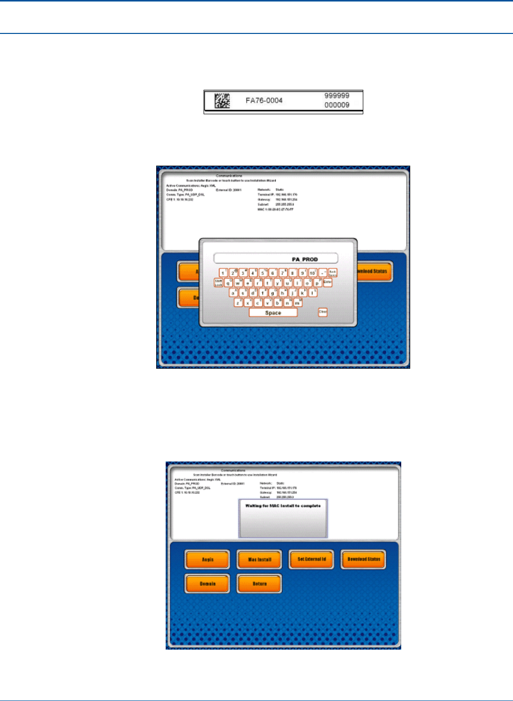
8. Either manually key in the last 5 digits of the 12-digit terminal serial number on the
side/rear of the terminal or use the wireless barcode reader to scan the terminal
serial barcode to enter the External ID. Example:
Figure 11: Sample External ID
9. Touch [Domain] to modify the domain, if necessary.
Figure 12: Modify Domain pop-up
10. The final step of the installation involves pressing the [MAC Install] button. See
the Aegis document regarding MAC Installation for more details. If successful, a
pop-up displays “Success”. While the MAC transaction is being sent, the following
pop-up is displayed:
Figure 13: MAC Install Success pop-up
PAT Technical Manual Installation Procedures
Confidential & Proprietary 3-9
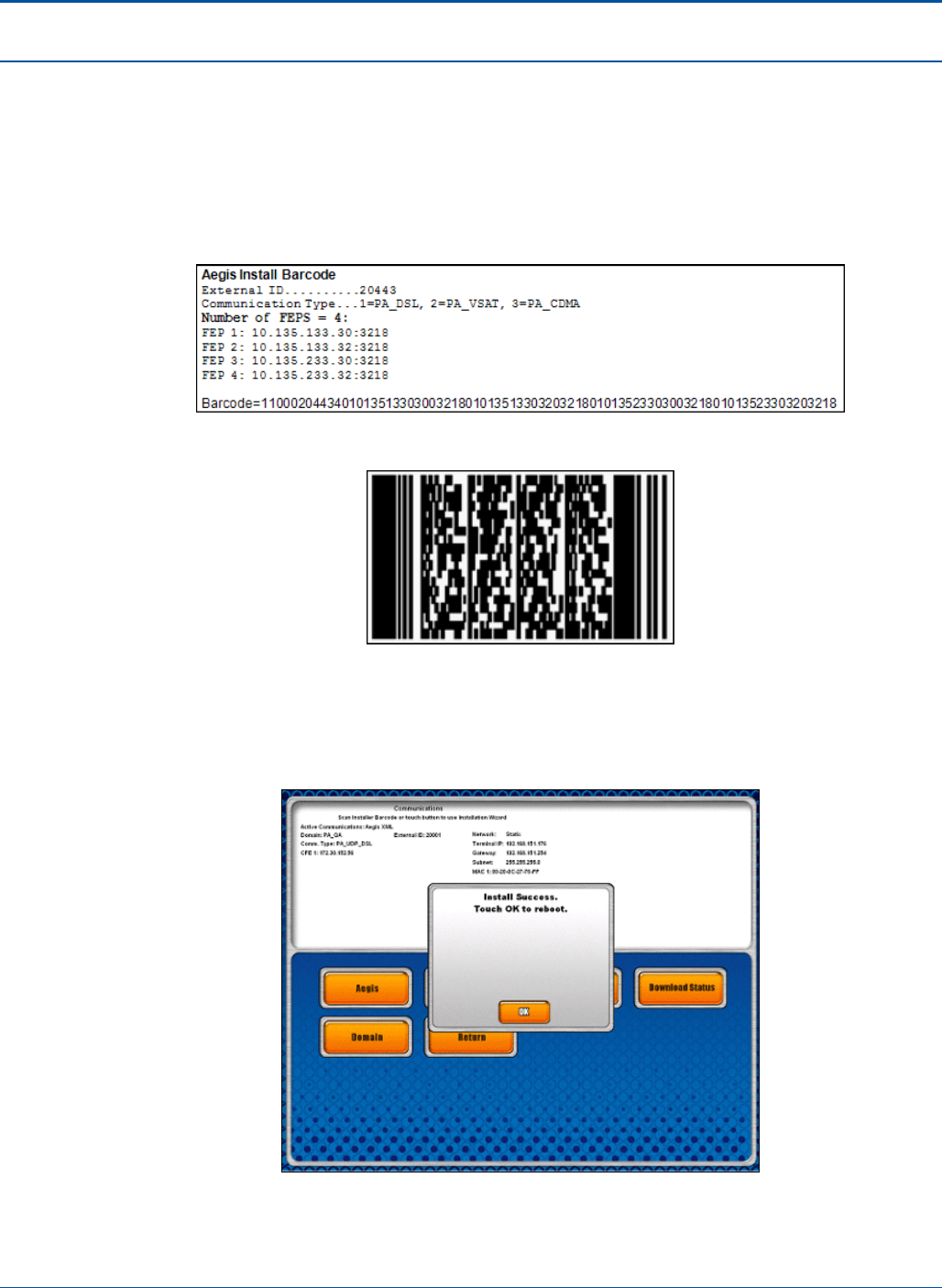
3.6 Aegis Bar Code Method
As an alternative to the Install method, a 2D bar code can be used instead. This bar code
must be scanned with the side scanner from the Diagnostics - Communications screen in
identical fashion to the Master Link bar code installation. Following is a sample Aegis
Install bar code:
Figure 14: Sample Aegis Install Bar Code
Figure 15: Sample Aegis Bar Code
1. When the bar code is scanned in Diagnostics – Communications, the terminal will
initialize the communications subsystem with the installation parameters from the
bar code. If successful, the following prompt is displayed:
Figure 16: Install Success pop-up
Installation Procedures PAT Technical Manual
3-10 Confidential & Proprietary
2. After the reboot, the FE should wait 2-3 minutes for the terminal to automatically
sign on, and then print a host report, to confirm connectivity. Online games should
appear on the main as well.
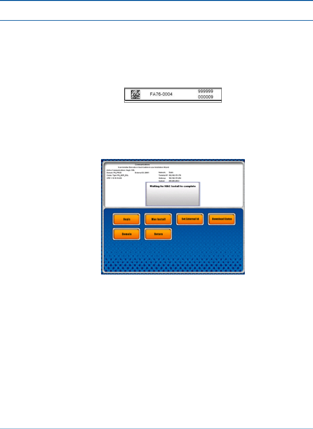
3. Touch [Set External Id] to display the following pop-up to enter this value.
4. Use the wireless bar code reader to scan the serial number bar code on the back
of the terminal.
Figure 17: Sample External ID
5. The final step of the installation involves pressing the [MAC Install] button. See
the Aegis document regarding MAC Installation for more details. If successful, a
pop-up displays “Success”. While the MAC transaction is being sent, the following
pop-up is displayed:
Figure 18: MAC Install Success pop-up

PAT Technical Manual Installation Procedures
Confidential & Proprietary 3-11
3.7 Configure PCT Communications
1. Allow the terminal to fully boot into the application.
2. Open front door or turn the red dotted key and login using 911911.
3. Make sure paper is loaded in the terminal printer.
4. Touch [Comm Diags].
5. Touch [Network Config].
6. Touch [FEP List].
7. Remove any existing FEP’s from the software using the [Remove FEP] button.
8. Touch [Add FEP].
9. Key in appropriate Primary FEP address.
• 192.168.140.37
10. Key in appropriate port number.
• 5400
11. Key in appropriate Secondary FEP addresses.
• 192.168.140.38
• 192.168.141.37
• 192.168.141.38
12. Key in appropriate port number.
• 5400
13. Touch [Network Config].
14. Touch [Setup Retailer].
15. Key in the appropriate jurisdiction number (123).
16. Key in the appropriate line number, and touch [OK].
17. Key in the appropriate poll number, and touch [OK].
18. Key in Installer BC, and touch [OK] - (0016327318313854778198)
19. Key in Installer ID, and touch [OK] - (1)
20. Key in Installer PW, and touch [OK] - (778198)
21. Key in Retailer PRN, and touch [OK].
22. Key in Retailer PW, and touch [OK].
23. Key in Installer WO, and touch [OK] - (0000016601)

Installation Procedures PAT Technical Manual
3-12 Confidential & Proprietary
24. Touch [Install]. If properly configured and connected you will get an Installation
Successful message.
25. After the “Successful Install” message displays, touch [Return to Main Menu].
26. Touch [Tech Functions].
27. Set Password One (1) (Initial Retailers password (IRP)).
28. Set Password Two (add 222222’s).
29. Set Machines ID (machine ID equals the terminals serial number but drop the
zero).

PAT Technical Manual Installation Procedures
Confidential & Proprietary 3-13
3.8 PCT Installation Checklist
1. Open Door
a. Red key = door open, Blue key = Reports, Green key = Bill Acceptor,
Smaller key (no color) = Cash box and Black key = Electronic
2. Once opened replace hard drive if required
a. If hard drive is replaced touch screen needs to be re-calibrated
3. Load paper (paper roll should feed from the top of the roll)
4. Re-calibrate touch screen if hard drive has been replaced
5. Configure PCT IP’s under the network connections within windows
6. Go to the desktop and open the “Phase 2” application (this will launch Aegis)
7. Go to the communication diagnostic
8. Scan PDF if available, if not enter manually
9. Scan or manually enter the External ID” and call the NRO
10. Upon the NRO has set the external ID, sent the Mac address
11. Verify with the NRO that the Mac address has been received
12. Once the Mac address has been received
13. Reboot the PAT
a. If the terminal is still booting into the desktop, locate the icon “lockreg”
b. Answer “Yes” to the pop up. This will ensure that upon the next re-boot the
terminal will come up in Master Link
Installation Procedures PAT Technical Manual
3-14 Confidential & Proprietary
3.9 Pinging Process
1. Connect keyboard to the USB port on the underside of the electronic tray.
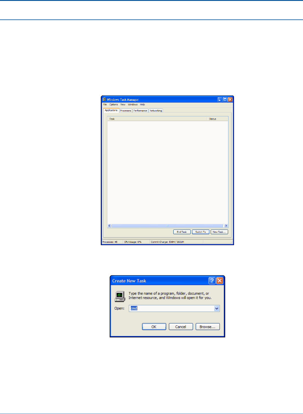
2. Press <F9>. This will close out the running application and bring you into windows.
3. Press/Select <CTRL>, <ALT> & <DELETE> at the same time.
4. Select [Task Manager].
Figure 19: Windows Task Manager screen
5. Select [New Task].
Figure 20: Create New Task pop-up

PAT Technical Manual Installation Procedures
Confidential & Proprietary 3-15
6. Type cmd and press [OK]. This opens the command screen.
Figure 21: Task Manager Screen
7. At the prompt, type the following: [ping(sp)IP number] and select <RETURN>.
Example: c:\Documents and Settings> ping 10.117.168.65
8. Verify that you received a return message indicating a successful ping.

4-1 Confidential & Proprietary
SECTION 4
QUALITY CONTROL (QC) TESTING
4.1 Overview
This chapter provides Quality Control (QC) testing procedures for the PCT terminal.
4.2 Tools and Materials
The following tools and equipment are required in order to perform Quality Control (QC)
testing procedures.
Required Tools and Materials Additional Information
1 Roll of certified Thermal Printer Paper RICOH 130LSB
Gray Scale Test Slips SGI Part No. TL20-0006
Network RJ45 Loopback Tester
No. 1 Phillips Head Screwdriver
Online Test Tickets
Play Slips for All Available Games
Serial DB9 Loopback Tester
Stylus Pen or equivalent
Voided Instant Tickets
Table 11: QC Required Tools and Materials

Quality Control (QC) Testing PAT Technical Manual
4-2 Confidential & Proprietary
4.3 Setting up the Terminal
Perform the following steps to set up the terminal.
1. Remove a terminal from the shipping pallet.
2. Check for any physical damage that may have occurred during shipping on all
components. (Assuming there is no physical damage, proceed with the
installation.)
3. Locate the power cable at the back of the terminal.
4. Note: Do not plug the power cord into an electrical outlet until instructed to do so.
5. Place the terminal in the desired retailer location. Make sure that there is at least 1
inch / 2.54 cm of space on all sides of the terminal for proper air circulation. This
will prevent the components from overheating.
6. Plug the terminal’s power cord into the outlet.
7. Turn on the power after insuring the terminal has been connected correctly.
8. Perform routine terminal diagnostic procedures.
a. Load paper into the printer.
b. Printer test
• Print 5 to 10 and verify print quality
c. Scan the printed tickets
• Verify scanned ticket printed a receipt
• Scan a couple play slips, verifying the printed receipt is correct
d. Barcode Reader
• Scan several barcodes. Verify correct results
e. Verify display and touch screen is functioning properly
f. Verify the customer display is properly displaying information
g. Communication Configuration and testing
• See communication setup section
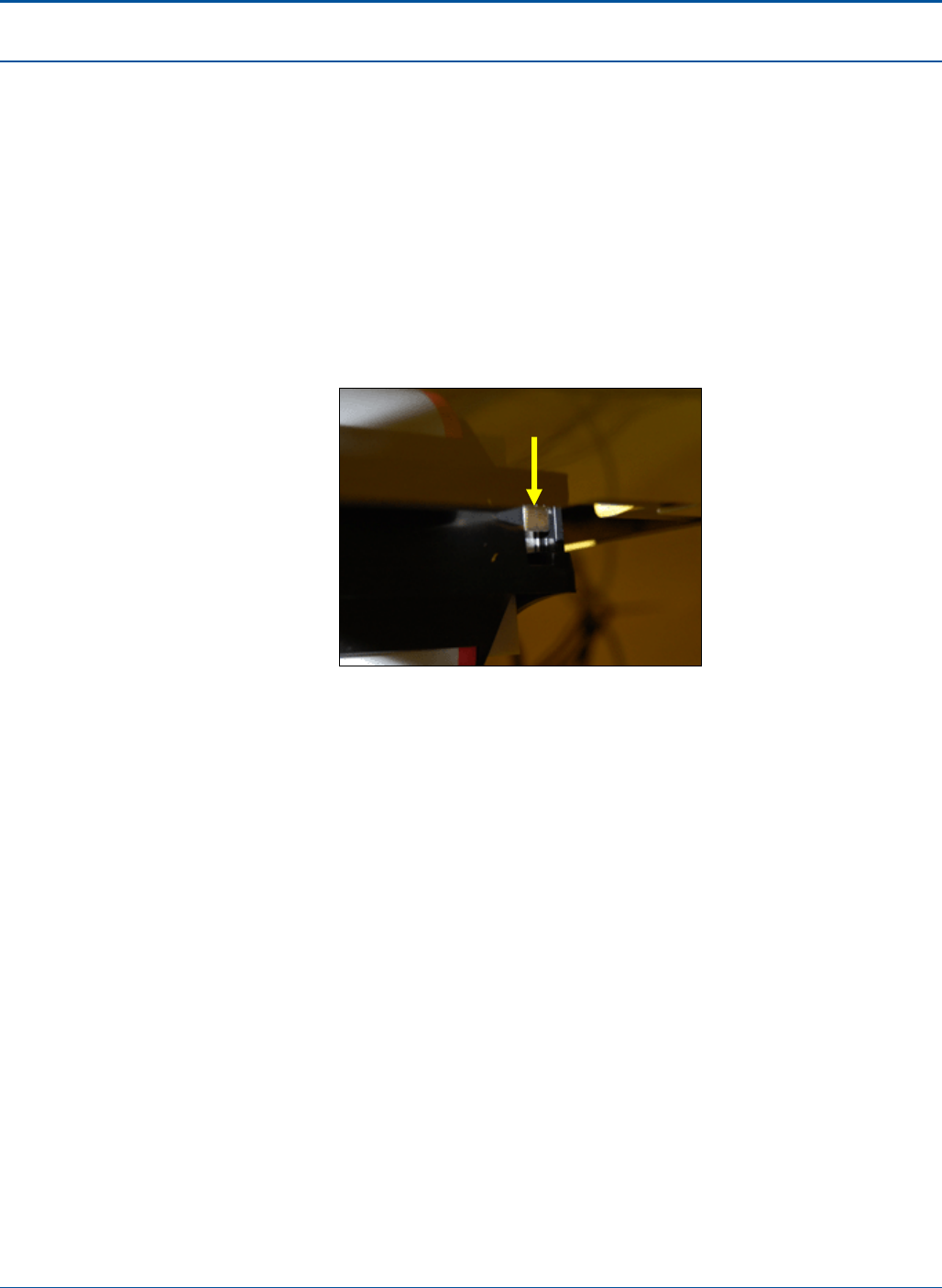
PAT Technical Manual Quality Control (QC) Testing
Confidential & Proprietary 4-3
4.4 Loading Online Paper
To load paper into the PCT printer, the retailer must perform the following steps:
1. Open the PCT by performing the following steps:
a. Insert the red key into the lower keyhole on the side panel and turn the key.
b. Lift the PCT door handle on the side panel.
c. Open the PCT door.
2. Release the print head by pulling up on the latch located on top-right side of the
printer.
Figure 22: Print Head Release Latch
3. Remove any paper and push the print head firmly back into place, making sure
that the print head is locked into place. (The print head makes an audible click
when it is locked.)
4. Remove used roll from printer well. (Do not throw away paper spindle.)
5. Place paper spindle through new paper roll.
6. Place the new roll of paper and spindle onto the paper well brackets, feeding the
paper from the bottom of the roll.
7. Insert the leading edge of paper under the print head. Push the edge into the slot
and through the paper guide as far as it will go, about 1 inch. The printer will then
automatically feed the paper and will cut off any excess paper.
8. Close and secure the PCT by performing the following steps:
a. Lift the PCT door handle on the side panel.
b. Shut the PCT door.
c. Lock the PCT door and remove the red key.
NOTE: The key can be removed only in the locked position.
Print Head Release
Latch
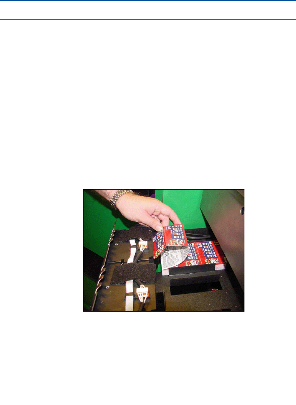
Quality Control (QC) Testing PAT Technical Manual
4-4 Confidential & Proprietary
4.5 Loading Instant Tickets
Perform the following steps to load paper into the printer.
1. Insert the blue key into the top barrel lock and turn the key.
2. Touch [Burster Status].
3. Touch the green [Load Pack] button for the empty dispenser.
4. On the pop-up screen, scan or enter the game or pack number.
5. Either scan the Pack Activity Card, scan the instant ticket validation barcode, or
manually enter the game/pack number.
6. After the game/pack number displays, touch [OK].
7. Touch [YES] to load a pull pack or [NO] to load a partial pack. If loading a full
pack, go to step 10
8. Enter the starting ticket and touch [OK].
9. Enter the ending ticket and touch [OK].
10. Open the drawer and insert the lowest numbered ticket into the burster.
Figure 23: Inserting Instant Tickets into Burster
11. If the ticket is loaded correctly, the “Successfully Loaded” message pop-up
displays.
12. Touch [OK] and close the drawer.

PAT Technical Manual Quality Control (QC) Testing
Confidential & Proprietary 4-5
4.6 Final QC Testing Steps
Perform the following procedures:
1. Complete QC Testing checklists.
2. Record asset information.
Perform the following steps for QC Testing overview:
1. Complete a QC Testing Checklist for each terminal in order to record the terminal
serial number and all of the external part serial numbers for the purposes of asset
tracking (See QC Testing Checklist at the end of this section for a copy of the QC
Testing Checklist).
2. Store all field-ready terminals (those that have passed QC testing) in a designated
area.
3. Place any terminals that failed QC testing in an area designated for terminals
waiting for repair.
4. As soon as possible after being recorded, record the asset tracking information in
the Remedy system.
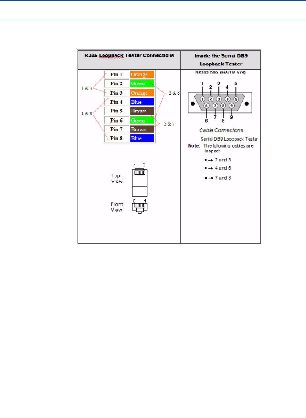
Quality Control (QC) Testing PAT Technical Manual
4-6 Confidential & Proprietary
4.7 Loopback Testers Illustrated
Figure 24: Loopback Testers Illustrated

5-1 Confidential & Proprietary
SECTION 5
DIAGNOSTICS
5.1 Overview
This chapter describes the hardware tests, which should be performed during the quality
assurance process of the PCT manufacturing.
Here we are focusing on the test functions provided by the terminal application. Other
standard hardware tests, which are performed during the production of terminals, are
described on a high level.
5.2 Diagnostics Screens
This section provides descriptions of the PCT diagnostics screens. They include:
• Printer Test
• Burster Test
• Scanner Test
• Interface Board
• Mother Board
• Burn-In Test
• SGI Engine
• SGI Engine FW
• Bill Accepter
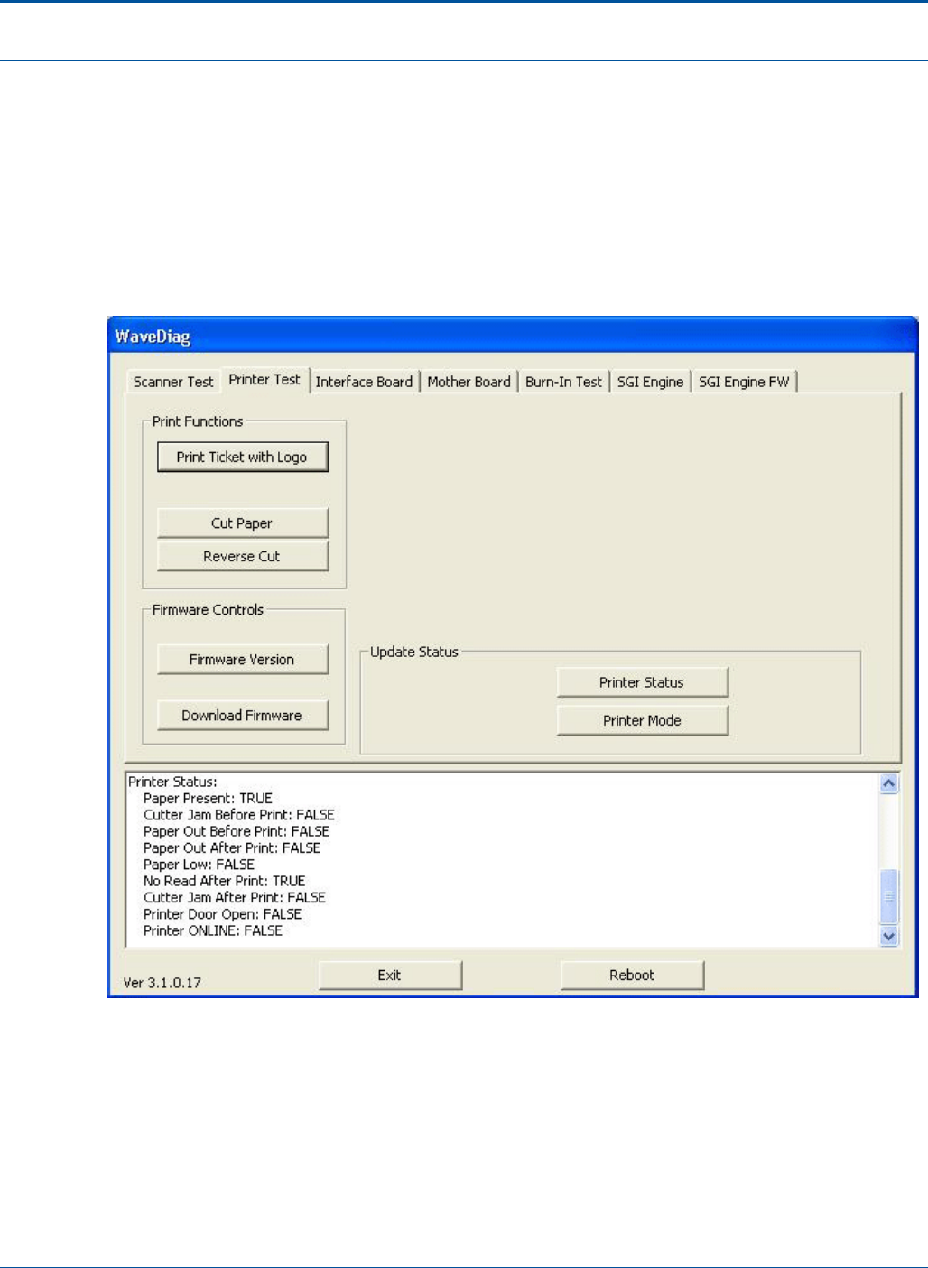
Diagnostics PAT Technical Manual
5-2 Confidential & Proprietary
5.3 Printer Test Screen
The printer test tab is divided into the following areas:
• Print Functions
• Firmware Controls
• Update Status
The functions located in each of these areas are described below.
Figure 25: Printer Test Screen

PAT Technical Manual Diagnostics
Confidential & Proprietary 5-3
5.3.1 Print Functions
The following selections are provided in the Print Functions area of the Printer Test tab:
5.3.1.1 Print Ticket with Logo
Description
Select this option to print a ticket containing a logo.
Preconditions
Unit must be operational.
Starting the Test
Select Print Ticket with Logo from the Print Functions area.
Flow
When this option is selected a ticket containing a logo is printed.
Ending the Test
The test ends automatically when the test is printed.
Analyzing Test Results
The test is successful if the ticket with logo is printed.
Exceptions
Unit does not print a ticket with logo.
Corrective Actions
DNA

Diagnostics PAT Technical Manual
5-4 Confidential & Proprietary
5.3.1.2 Cut Paper
Description
Select this option to cut printer paper.
Preconditions
Unit must be operational.
Starting the Test
Select Cut Paper from the Print Functions area.
Flow
When this option is selected the paper is advanced and cut.
Ending the Test
The test ends automatically when the paper is cut.
Analyzing Test Results
The test is successful if the paper is cleanly and evenly cut.
Exceptions
Unit does not cut paper or does not cut cleanly or evenly.
Corrective Actions
Adjust or replace the blade.
5.3.1.3 Reverse Cut
This feature is currently not available.
5.3.2 Firmware Controls
The following selections are provided in the Firmware Controls area of the Printer Test
tab:
Firmware Version – When selected provides the currently loaded firmware version.
Download Firmware - When selected provides a path to download firmware.
5.3.3 Update Status
The following selections are provided in the Update Status area of the Printer Test tab:
Printer Status – When selected provides a status on printer outputs (i.e. Paper Low, Door
Open, etc...).
Printer Mode – When selected provides the printer and brander duty cycle.
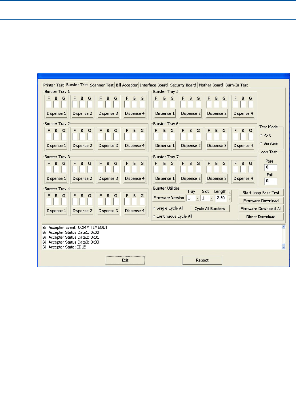
PAT Technical Manual Diagnostics
Confidential & Proprietary 5-5
5.4 Burster Test Screen
Located on the Burster Test tab are options for the seven burster trays as well as
numerous burster options. To perform burster tests, select the relevant options then
press the appropriate diagnostic button.
Figure 26: Burster Test Screen

Diagnostics PAT Technical Manual
5-6 Confidential & Proprietary
5.4.1 Burster Tray
The following selections are provided in the Burster Tray areas of the Burster Test tab:
5.4.1.1 Dispense
Description
Select this option to dispense ticket from desired burster.
Preconditions
Unit must be operational and buster loaded.
Starting the Test
Select dispense 1, 2, 3, or 4 on desired tray.
Flow
Selected burster will separate and dispense ticket.
Ending the Test
Test ends automatically when ticket is dispensed.
Analyzing Test Results
Test is successful if dispensed ticket loads in tray.
Exceptions
Ticket does not separate or land in tray.
Corrective Actions
Ensure all cables and mechanical parts are positioned correctly.
F – Option for Front sensor (not used at this time).
B - Option for Back sensor (not used at this time).
G - Option for Gate sensor (not used at this time).
5.4.2 Test Mode
The following selections are provided in the Test Mode area of the Burster Test tab:
Port - Not used.
Bursters – To be selected for burster test

PAT Technical Manual Diagnostics
Confidential & Proprietary 5-7
5.4.3 Loop Test
The following selections are provided in the Loop Test area of the Burster Test tab:
Pass – Option not used at this time.
Fail – Option not used at this time.
5.4.4 Burster Utilities
The following selections are provided in the Burster Utilities area of the Burster Test tab:
• Firmware Version – When selected provides the currently loaded firmware version.
• Cycle All Bursters – Select to start burster cycle
• Start Loopback Testing - Select this option to test the burster utilities.
• Firmware Download - When selected provides a path to download firmware.
• Firmware Download All - When selected provides a path to download all available
firmware.
• Direct Download – Option not available.
• Single Cycle All – Select to cycle all loaded busters once.
• Continuous Cycle All – Select to continuously cycle all loaded busters until empty.
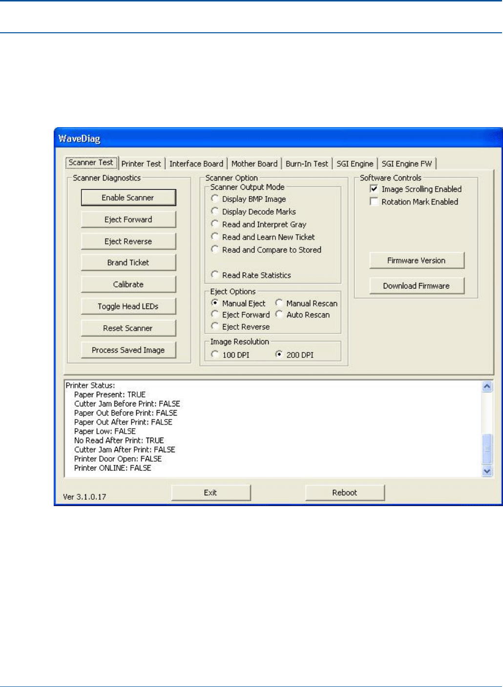
Diagnostics PAT Technical Manual
5-8 Confidential & Proprietary
5.5 Scanner Test Screen
Located on the Scanner Test tab are eight scanner diagnostic buttons as well as
numerous scanner setting options. To perform scanner tests, select the relevant scanner
options then press the appropriate diagnostic button.
Figure 27: Scanner Test Screen

PAT Technical Manual Diagnostics
Confidential & Proprietary 5-9
5.5.1 Scanner Diagnostics
The following selections are provided in the Scanner Diagnostics area of the Scanner
Test tab:
5.5.1.1 Enable Scanner
Description
Select this option to activate the scanner. When this option is selected, the scanner will
accept items for scanning.
Preconditions
Unit must be operational.
Starting the Test
Select [Enable Scanner] from the Scanner Diagnostics area.
Flow
When this option is selected the scanner becomes active and will accept items for
feeding.
Ending the Test
DNA
Analyzing Test Results
The scanner should accept an item for feeding. If the scanner accepts the item, this
diagnostic is considered to be successful.
Exceptions
Scanner does not accept item for feeding
Corrective Actions
Make sure Enable Scanner is selected and item properly fed.

Diagnostics PAT Technical Manual
5-10 Confidential & Proprietary
5.5.1.2 Eject Forward
Description
Select this item to eject any item in the scanner drive in a forward direction.
Preconditions
Unit must be operational.
Starting the Test
Select [Eject Forward] from the Scanner Diagnostics area.
Flow
When this option is selected the scanner ejects any item in the scanner drive in a forward
direction. If no item is currently in the scanner drive, the drive mechanism operates for
approximately one second. After this interval a new item may be fed into the scanner.
Ending the Test
The test ends automatically.
Analyzing Test Results
If the scanner ejects the item in the drive or is heard to be operating if no item is in the
drive, the test is successful.
Exceptions
Scanner does not operate/eject item.
Corrective Actions
Make sure item in drive is not jammed.
NOTE: Even if item is jammed, the drive mechanism should be heard to operate.

PAT Technical Manual Diagnostics
Confidential & Proprietary 5-11
5.5.1.3 Eject Reverse
Description
Select this item to eject any item in the scanner drive in a backward direction.
Preconditions
Unit must be operational.
Starting the Test
Select [Eject Reverse] from the Scanner Diagnostics area.
Flow
When this option is selected the scanner ejects any item in the scanner drive in a
backward direction. If no item is currently in the scanner drive, the drive mechanism
operates for approximately one second. After this interval a new item may be fed into the
scanner.
Ending the Test
The test ends automatically.
Analyzing Test Results
If the scanner ejects the item in the drive or is heard to be operating if no item is in the
drive, the test is successful.
Exceptions
Scanner does not operate/eject item.
Corrective Actions
Make sure item in drive is not jammed.
NOTE: Even if item is jammed, the drive mechanism should be heard to operate.
5.5.1.4 Brand Ticket
Description
Select this button to brand a ticket.
Preconditions
Unit must be operational and scanner enabled. Eject option must be set to Manual Eject.
Flow
Feed ticket into scanner then select [Brand Ticket] from the Scanner Diagnostics area.
The unit brands the ticket and displays the result in the message window at the bottom of
the screen.
Ending the Test
The test ends automatically.

Diagnostics PAT Technical Manual
5-12 Confidential & Proprietary
Analyzing Test Results
The test is successful if the ticket is branded and the following message appears in the
message box: Brand Status: Brand OK
Exceptions
Ticket is not branded. Brand Status: Brand OK message is not displayed.
Corrective Actions
DNA
5.5.1.5 Calibrate
Description
Select this button to calibrate the scanner.
Preconditions
Unit must be operational and scanner enabled.
Flow
Select [Calibrate] from the Scanner Diagnostics area and feed an 8 ½ X 4 inch piece of
white paper into scanner. This procedure calibrates the distance between the paper
source and the light source, providing a precise measurement between the two.
Ending the Test
The test ends automatically.
Analyzing Test Results
The test is successful if the ticket is branded and the following message appears in the
message box: Brand Status: Brand OK
Exceptions
Ticket is not branded. Brand Status: Brand OK message is not displayed.
Corrective Actions
DNA
5.5.1.6 Toggle Head LEDs
Description
Select this button to toggle on and off Head LEDs.
Preconditions
Unit must be operational.

PAT Technical Manual Diagnostics
Confidential & Proprietary 5-13
Flow
Select [Toggle Head LEDs] from the Scanner Diagnostics area several times. Each time
the button is selected the Head LEDs will alternately turn on and off.
Ending the Test
The test ends when the user stops selecting the related button.
Analyzing Test Results
The test is successful if Head LEDs turn on and off alternately with each button selection.
Exceptions
LEDs do not turn on and off as the Toggle Head LCDs button is selected.
Corrective Actions
DNA
5.5.1.7 Reset Scanner
Description
Select this button to reset the scanner
Preconditions
Unit must be operational.
Flow
Select [Reset Scanner] from the Scanner Diagnostics area. When selected, a reset
command is sent to the scanner.
Ending the Test
The test ends automatically.
Analyzing Test Results
The test is successful if the scanner is reset.
Exceptions
Scanner is not reset.
Corrective Actions
DNA

Diagnostics PAT Technical Manual
5-14 Confidential & Proprietary
5.5.1.8 Process Saved Image
Description
This option is used in conjunction with the options listed in the Scanner option-Scanner
Output Mode section. Select this button to process the most recently scanned image
according to the Scanner Output mode selected. The scanned option is displayed.
Preconditions
Unit must be operational.
Flow
1. Select the relevant option from the Scanner Output Mode area
2. Press Process Saved Image. The relevant information is displayed for the last item
scanned. If a new item is fed into the scanner the information on the new item is
displayed.
Ending the Test
The test ends when the user exits.
Analyzing Test Results
The test is successful if image of the scanned item is displayed.
Exceptions
Image of scanned item is not displayed.
Corrective Actions
Replace scanner.

PAT Technical Manual Diagnostics
Confidential & Proprietary 5-15
5.5.2 Scanner Options
The following selections are provided in the Scanner Options area of the Scanner Test
tab:
5.5.2.1 Scanner Output Mode
• Display BMP Image - Displays a bitmap (BMP) image of the scanned item.
• Display Decode Marks - Displays the decode marks of the scanned item.
• Read and Interpret Gray - Reads and interprets the gray areas of the scanned
item. A calibration slip is required for this option.
• Read and Learn New Ticket - Scanned ticket is stored.
• Read and Compare to Stored - Scanned image is compared to the stored image.
The result is displayed in the message area at the bottom of the screen.
• Read Rate Statistic - The rate statistics of the scanned image are displayed in the
message area at the bottom of the screen.
5.5.2.2 Eject Options
Manual Eject - The scanned item does not feed through completely and must be
manually removed from the scanner.
Eject Forward - The scanned item feeds entirely through the scanner.
Eject Reverse - The scanned item feeds through the scanner and then ejects the item
backwards.
Manual Rescan - Select to manually rescan an item. Feed item into scanner upon
selection of this option.
Auto Rescan - ???
5.5.2.3 Image Resolution
100 DPI - Resolution of scanned image will be 100 dots per inch.
200 DPI - Resolution of scanned image will be 200 dots per inch.
5.5.2.4 Software Controls
Image Scrolling Enabled - Select to allow scrolling of on screen of scanned image.
Rotation Mark Enabled – Select to allow the reading of ticket rotation mark.
Firmware Version – When selected provides the currently loaded firmware version.
Download Firmware - When selected provides a path to download firmware.
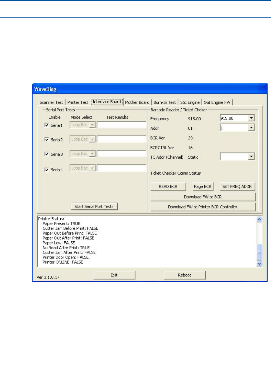
Diagnostics PAT Technical Manual
5-16 Confidential & Proprietary
5.6 Interface Board Screen
The Interface Board tab is divided into the following areas:
• Serial Port Tests
• Barcode Reader/Ticket Checker
The functions located in each of these areas are described below.
Figure 28: Interface Board Screen

PAT Technical Manual Diagnostics
Confidential & Proprietary 5-17
5.6.1 Serial Port Tests
The following selections are provided in the Serial Port Tests area of the Interface Board
tab:
5.6.1.1 Serial Port Test
Description
Select this option to test the terminal’s serial ports.
Preconditions
Unit must be operational. A Serial Loopback connector must be attached to the port
being tested.
Starting the Test
Select ports to test by placing a chicanery in the box next to each port to be tested.
Select the relevant mode for each port by making a selection from the dropdown menu
located next to each port. Select the [Start Serial Port Test] button to begin testing.
Flow
Once the testing has started, the result for each port is displayed in the Test Results box
located next to each port. The ports are continually tested with the results being
continually updated until the test is stopped by the user.
Ending the Test
Select the [Stop Serial Test] button ([Start] button now relabeled as [Stop]).
Analyzing Test Results
The number of passes and fails for each port are displayed in the Test Results boxes.
Exceptions
DNA
Corrective Actions
DNA

Diagnostics PAT Technical Manual
5-18 Confidential & Proprietary
5.6.1.2 Barcode Reader/Ticket Checker
Frequency
This feature is currently not available.
Address (Addr)
This feature is currently not available.
BCR Version
Determines the firmware level of the symbol barcode reader.
BCRCTR Version
Determines the firmware level of the controller board.
TC Address (Addr) Channel
This feature is currently not available.
5.6.1.3 Read BCR
Displays the frequency, address and the BCR version of the barcode reader.
5.6.1.4 Page BCR
This feature is currently not available.
5.6.1.5 Set Frequency Address
This feature is currently not available.
5.6.1.6 Download FW to BCR
Provides a path to download firmware to the barcode reader.
5.6.1.7 Download FW to Printer BCR Controller
Provides a path to download firmware to the BCR Controller.
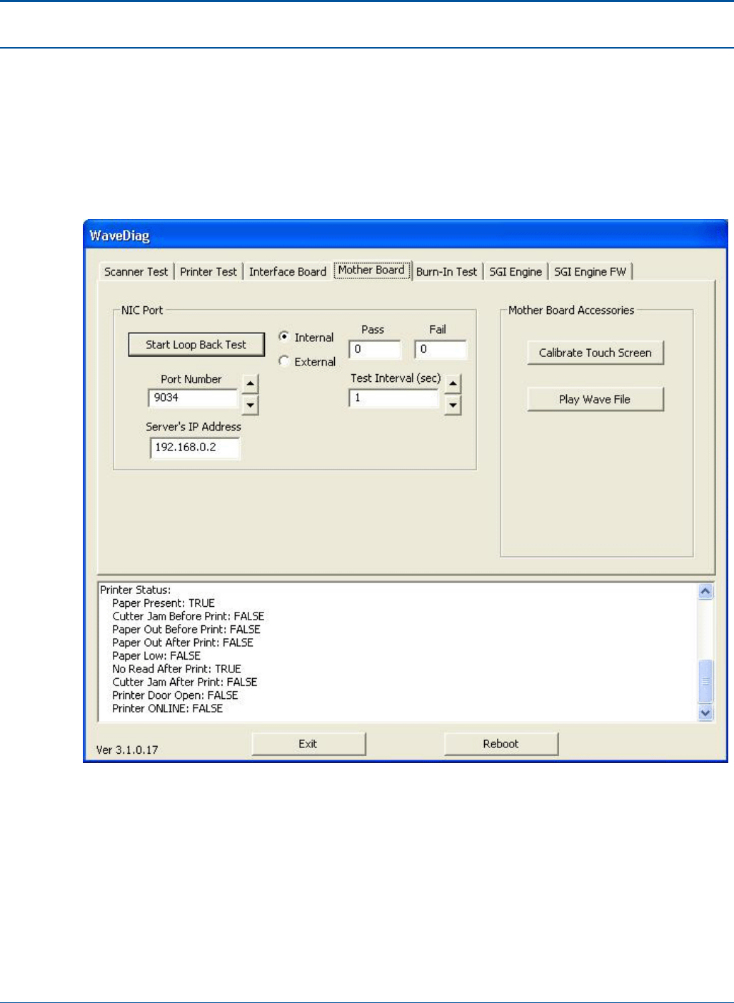
PAT Technical Manual Diagnostics
Confidential & Proprietary 5-19
5.7 Mother Board Screen
The Mother Board tab is divided into the following two areas:
• NIC port
• Mother Board Accessories
The options and functions located in each of these areas are described below.
Figure 29: Interface Board Screen

Diagnostics PAT Technical Manual
5-20 Confidential & Proprietary
5.7.1 NIC Port
The following selections are provided in the NIC Port area of the Mother Board tab:
5.7.1.1 Start Loop Back Test
Description
Select this option to test the NIC port.
Preconditions
Unit must be operational.
Starting the Test
Select internal or external.
Use the up and down arrows to select the port number.
Enter the relevant IP address in the Server’s IP Address field.
Use the up and down arrow to enter the desired test interval in second in the Test Interval
(sec) field. Value can be between 0 and 1000.
Press the [Start Loop Back Test] button to begin testing.
Flow
Once the testing has started, the relevant port is continuously tested at the selected
interval until the user stops the test. The results of the test are displayed in the Pass and
Fail fields. Each test iteration increments the number in either the Pass or Fail field
depending on the test result.
Ending the Test
Select the [Stop Loopback Test] button ([Start] button now relabeled as [Stop]).
Analyzing Test Results
The number of passes and fails are displayed in the Pass and Fail fields, respectively.
Exceptions
DNA
Corrective Actions
DNA
Modem Port
This area of the Motherboard tab allows the user to test the modem port.

PAT Technical Manual Diagnostics
Confidential & Proprietary 5-21
5.7.2 Mother Board Accessories
The following selections are provided in the Mother Board Accessories area of the
Mother Board tab:
5.7.2.1 Calibrate Touch Screen
When selected launches the Touch Screen Calibration program.
5.7.2.2 Play Wave File
Description
Select this option to test the wave file.
Preconditions
Unit must be operational.
Starting the Test
Select Play Wave File from the Mother Board Accessories area.
Flow
After each successive selection of this button, the wave file plays.
Ending the Test
The test ends when the user stops pressing [Play Wave File].
Analyzing Test Results
The test is successful if the wave file plays when [Play Wave File] is selected.
Exceptions
Wave file does not play.
Corrective Actions
DNA
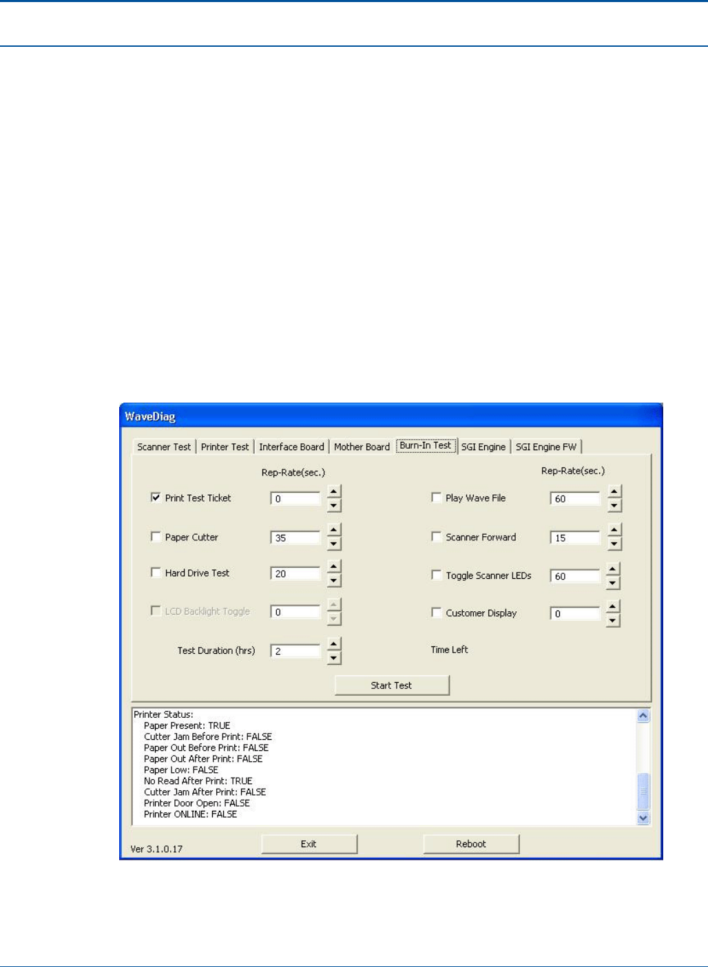
Diagnostics PAT Technical Manual
5-22 Confidential & Proprietary
5.8 Burn-In Test Screen
The Burn-In Test tab consists of a single are from which the following tests can be
performed over a set period of time:
• Print Test Ticket
• Paper Cutter
• Hard Drive Test
• LCD Backlight Toggle
• Test Duration (hrs)
• Play Wave File
• Scanner Forward
• Toggle Scanner LEDs
• Customer Display
• Time Left
Figure 30: Burn-In Test Screen

PAT Technical Manual Diagnostics
Confidential & Proprietary 5-23
5.8.1 Burn-In Tests
The tests contained on the Burn-In Test tab can be performed simultaneously in any
combination, with the repetition rate for each test being set independently from zero to
10,000 seconds.
The tests and related options are described below.
5.8.1.1 Print Test Ticket
Description
Select this option to print test tickets.
Preconditions
Unit must be operational.
Starting the Test
1. Select test to be performed by checking the box next to test.
2. Set the repetition rate for the test. The repetition rate is given in seconds and must
be between 0 and 10,000.
3. Set the test duration. The duration is set in hours and must be between 0 and
10,000.
4. Press the [Start Test] button to begin testing.
NOTE: If test duration is set to 0, the system will immediately indicate that the test
is complete, even though no testing is performed.
Flow
Once the test is started, the system performs the selected test at the set repetition rate
for the selected number of hours or until the user stops the manually.
Ending the Test
The test ends when the entered test duration has expired or when the user selects the
[Stop Test] button ([Start] button now relabeled as [Stop])
Analyzing Test Results
Verify that the ticket prints at the selected rate.
Exceptions
None
Corrective Actions
None

Diagnostics PAT Technical Manual
5-24 Confidential & Proprietary
5.8.1.2 Paper Cutter
Description
Select this option to test the paper cutter. For each repetition of the test, paper is
advanced and cut.
Preconditions
Unit must be operational.
Starting the Test
1. Select test to be performed by checking the box next to test.
2. Set the repetition rate for the test. The repetition rate is given in seconds and must
be between 0 and 10,000.
3. Set the test duration. The duration is set in hours and must be between 0 and
10,000.
4. Press the [Start Test] button to begin testing.
NOTE: If test duration is set to 0, the system will immediately indicate that the test
is complete, even though no testing is performed.
Flow
Once the test is started, the system performs the selected test at the set repetition rate
for the selected number of hours or until the user stops the manually.
Ending the Test
The test ends when the entered test duration has expired or when the user selects the
[Stop Test] button ([Start] button now relabeled as [Stop]).
Analyzing Test Results
Verify that cutter cycles at the selected rate.
Exceptions
DNA
Corrective Actions
DNA

PAT Technical Manual Diagnostics
Confidential & Proprietary 5-25
5.8.1.3 Hard Drive Test
Description
Select this option to test the hard drive.
Preconditions
Unit must be operational.
Starting the Test
1. Select test to be performed by checking the box next to test.
2. Set the repetition rate for the test. The repetition rate is given in seconds and must
be between 0 and 10,000.
3. Set the test duration. The duration is set in hours and must be between 0 and
10,000.
4. Press the [Start Test] button to begin testing.
NOTE: If test duration is set to 0, the system will immediately indicate that the test
is complete, even though no testing is performed.
Flow
Once the test is started, the system performs the selected test at the set repetition rate
for the selected number of hours or until the user stops the manually.
Ending the Test
The test ends when the entered test duration has expired or when the user selects the
[Stop Test] button ([Start] button now relabeled as [Stop]).
Analyzing Test Results
DNA
Exceptions
DNA
Corrective Actions
DNA

Diagnostics PAT Technical Manual
5-26 Confidential & Proprietary
5.8.1.4 LCD Backlight Toggle
Description
Select this option to test LCD backlight.
Preconditions
Unit must be operational.
Starting the Test
1. Select test to be performed by checking the box next to test.
2. Set the repetition rate for the test. The repetition rate is given in seconds and must
be between 0 and 10,000.
3. Set the test duration. The duration is set in hours and must be between 0 and
10,000.
4. Press the [Start Test] button to begin testing.
NOTE: If test duration is set to 0, the system will immediately indicate that the test
is complete, even though no testing is performed.
Flow
Once the test is started, the system performs the selected test at the set repetition rate
for the selected number of hours or until the user stops the manually.
Ending the Test
The test ends when the entered test duration has expired or when the user selects the
[Stop Test] button ([Start] button now relabeled as [Stop]).
Analyzing Test Results
Test is successful, if backlight toggle action operates.
Exceptions
Light toggle action does not operate.
Corrective Actions
DNA
Test Duration
Set the amount of time selected for the duration of the test.
Play Wave File
Set the amount of time the wave file is to be played.

PAT Technical Manual Diagnostics
Confidential & Proprietary 5-27
5.8.1.5 Scanner Forward
Description
Select this option to test the scanner operation in a forward direction.
Preconditions
Unit must be operational.
Starting the Test
1. Select test to be performed by checking the box next to test.
2. Set the repetition rate for the test. The repetition rate is given in seconds and must
be between 0 and 10,000.
3. Set the test duration. The duration is set in hours and must be between 0 and
10,000.
4. Press the [Start Test] button to begin testing.
NOTE: If test duration is set to 0, the system will immediately indicate that the test
is complete, even though no testing is performed.
Flow
Once the test is started, the system performs the selected test at the set repetition rate
for the selected number of hours or until the user stops the manually.
Ending the Test
The test ends when the entered test duration has expired or when the user selects the
[Stop Test] button ([Start] button now relabeled as [Stop]).
Analyzing Test Results
The test is successful, if the item is scanned.
Exceptions
Item is not scanned.
Corrective Actions
DNA

Diagnostics PAT Technical Manual
5-28 Confidential & Proprietary
5.8.1.6 Toggle Scanner LEDs
Description
Select this option to test the scanner LEDs.
Preconditions
Unit must be operational.
Starting the Test
1. Select test to be performed by checking the box next to test.
2. Set the repetition rate for the test. The repetition rate is given in seconds and must
be between 0 and 10,000.
3. Set the test duration. The duration is set in hours and must be between 0 and
10,000.
4. Press the [Start Test] button to begin testing.
NOTE: If test duration is set to 0, the system will immediately indicate that the test
is complete, even though no testing is performed.
Flow
Once the test is started, the system performs the selected test at the set repetition rate
for the selected number of hours or until the user stops the manually.
Ending the Test
The test ends when the entered test duration has expired or when the user selects the
[Stop Test] button ([Start] button now relabeled as [Stop]).
Analyzing Test Results
The test is successful, if the scanner LED toggle action operates.
Exceptions
LED toggle action does not operate.
Corrective Actions
DNA
Customer Display
Set the amount of time a message is displayed on the Flat Panel Display.
Time Left
???
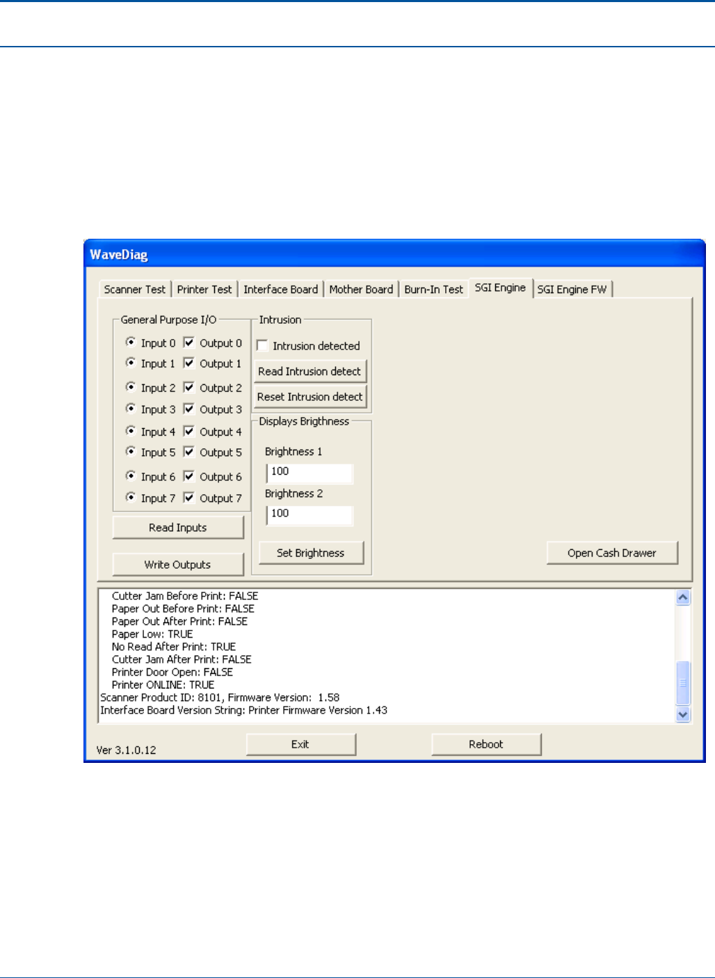
PAT Technical Manual Diagnostics
Confidential & Proprietary 5-29
5.9 SGI Engine Screen
The SGI Engine tab contains the following areas:
• General Purpose I/O
• Intrusion
• Display Brightness
The various options and tests located on the SGI Engine tab are described below.
Figure 31: SGI Engine Screen

Diagnostics PAT Technical Manual
5-30 Confidential & Proprietary
5.9.1 General Purpose I/O
5.9.1.1 Read Inputs
Inputs column is updated with the current status on input 0-7.
5.9.1.2 Write Outputs
Checked outputs will be set and unchecked cleared.
5.9.2 Intrusion
5.9.2.1 Reset Intrusion Detect
Current status is be shown in the intrusion detect field. If there has been an intrusion it is
checked, otherwise it is unchecked.
5.9.3 Displays Brightness
Write the decried level from 100 – 255 in the box for brightness 1 and brightness 2 you
want to change and press [Set Brightness].
NOTE: The WaveDiags will not set values outside the rage from 100 to 255.
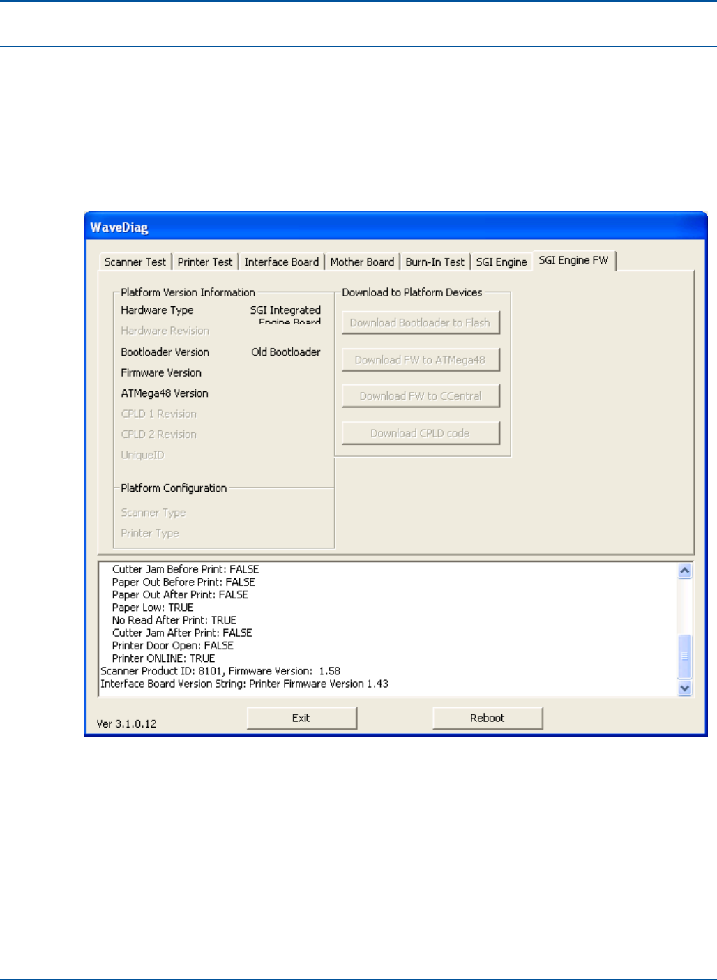
PAT Technical Manual Diagnostics
Confidential & Proprietary 5-31
5.10 SGI Engine FW Screen
The SGI Engine FW tab contains the following areas:
• Platform Version Information
• Platform Configuration
• Download to Platform Devices
Figure 32: SGI Engine FW Screen

Diagnostics PAT Technical Manual
5-32 Confidential & Proprietary
5.10.1 Platform Version Information
This area is informational only. It displays the values for the following:
• Hardware Type - Type of hardware located on the current platform (In this case
SGI Interface Board)
• Hardware Revision - The revision letter of the current hardware
• Bootloader Version - Version number of the bootloader in mm.dd.yy.nn format
• Firmware Version - Version number of the firmware in dd.mm.yy.nn format.
• ATMega48 Version - Version number of the ATMega 48 in dd.mm.yy.nn format
• CPLD 1 Revision - Revision number of the first CPLD
• CPLD 2 Revision - Revision number of the second CPLD
• Unique ID - Unique Identification number of the platform
5.10.2 Platform Configuration
This area is informational only. It displays the values for the following:
• Scanner Type - The type of scanner installed in the unit for example, 8 inch
Black/White
• Printer Type - The type of printer attached to the unit for example, 3 inch FTP639
Fujitsu

PAT Technical Manual Diagnostics
Confidential & Proprietary 5-33
5.10.3 Download to Platform Devices
This area contains the following buttons:
Download Bootloader to Flash
Download FW to ATMega48
Download FW to Central
Download CPLD code
5.10.3.1 Download Bootloader to Flash
Description
This function is used if the Bootloader Version is less than 2.02.05.00.
Preconditions
Unit must be operational.
Starting the Test
Select the [Download Bootloader to Flash] button.
Flow
Once the option is selected a windows navigation dialogue appears. Navigate to
c:\bootloader and select the relevant file.
When download finishes a message will appear in the Extrema Diag window.
Ending the Test
The test ends automatically when the bootloader has been downloaded.
Analyzing Test Results
Reboot PC to activate new Bootloader. The version will be displayed in the SGI Engine
FW tab of Extrema Diag.
Exceptions
If the Bootloader Version is equal to or greater than 2.02.05.00 this option must be
selected.
Corrective Actions
DNA

Diagnostics PAT Technical Manual
5-34 Confidential & Proprietary
5.10.3.2 Download FW to ATMega48
This option does not apply to this hardware configuration.
5.10.3.3 Download FW to Central
This option does not apply to this hardware configuration.
5.10.3.4 Download CPLD code
This option does not apply to this hardware configuration.
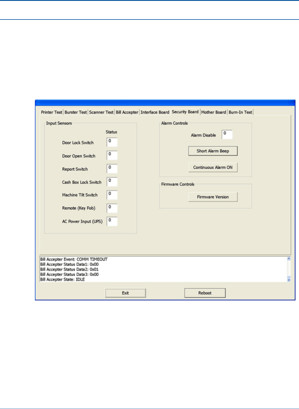
PAT Technical Manual Diagnostics
Confidential & Proprietary 5-35
5.11 Security Board Screen
The Security Board tab contains the following areas:
• Input Sensors
• Alarm Controls
• Firmware Controls
The various options and tests located on the Security Board tab are described below.
Figure 33: Security Board Screen

Diagnostics PAT Technical Manual
5-36 Confidential & Proprietary
5.11.1 Input Sensors
This area is informational only. It displays the values for the following:
• Door Lock Switch -
• Door Open Switch -
• Report Switch -
• Cash Box Lock Switch -
• Machine Tilt Switch -
• Remote (Key Fob) -
• AC Power Input -
5.11.2 Alarm Controls
This area is informational only. It displays the values for the following:
• Alarm Disable –
• Short Alarm Beep –
• Continuous Alarm ON -
5.11.3 Firmware Controls
This area is informational only. It displays the values for the following:
• Firmware Version - When selected provides the currently loaded firmware version.
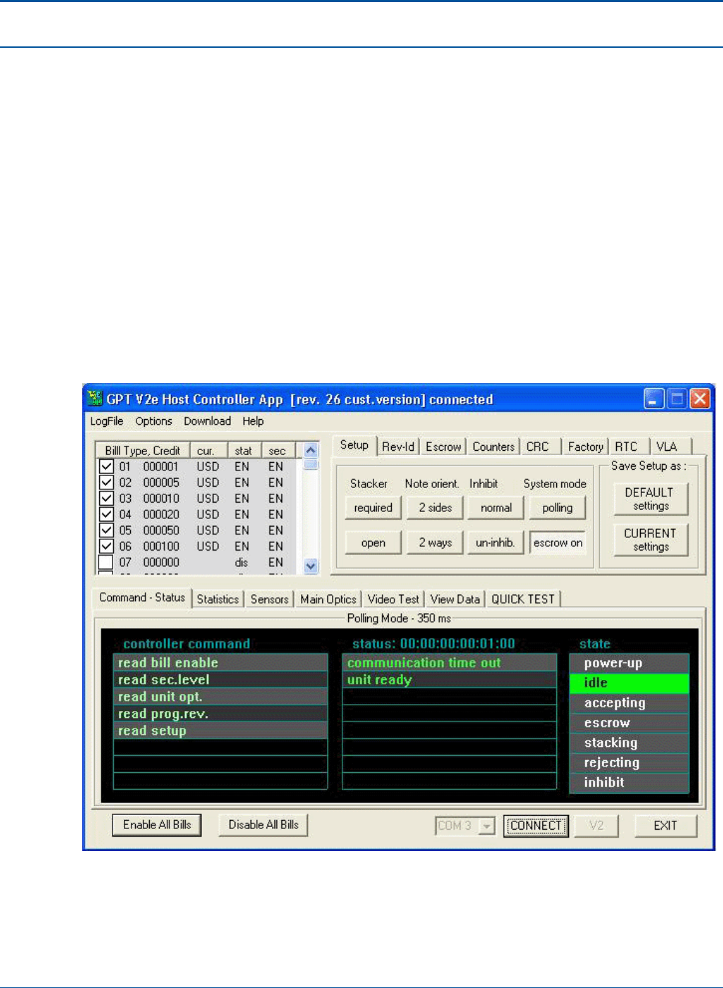
PAT Technical Manual Diagnostics
Confidential & Proprietary 5-37
5.12 Bill Accepter Screen
The Bill Accepter diagnostic functions are located in a separate program from the rest of
the terminal’s diagnostics. To access the Bill Accepter diagnostics, click the GPT V2e
icon. The technician will only use this screen to check or connect the communications for
the terminal.
To connect the communications, perform the following:
1. Double click the GPT V2e icon on the Windows desktop. The GPT V2e Host
Controller App screen displays.
2. Press [V2].
3. Ensure that COM3 is selected in the communication drop down.
4. Press [CONNECT].
Figure 34: Bill Accepter Screen

6-1 Confidential & Proprietary
SECTION 6
COMPONENT PROCEDURES
6.1 About this Section
The sections below provide the procedures for calibrating and/or configuring the following
PCT components:
• Document Scanner
• Touch Screen
• Bar code Reader (BCR)
6.1.1 Document Scanner Calibration
Procedures
• Access the PCT diagnostic using the diagnostic application provided.
• Once the PCT diagnostic has loaded, select the Scanner tab at the top.
• Within this field select Enable Scanner then Calibrate Scanner.
• Now simply feed together, several sheets of the white (4” X 11”) paper.
Required tools/equipment
• Several 4” X 11” white sheets of paper

Component Procedures PAT Technical Manual
6-2 Confidential & Proprietary
6.1.2 Touch Screen Calibration
There are three methods that allow you to calibrate the touch screen. Once the
calibration program has been opened, simply follow the instruction; touching each
displayed “+” in the middle. However all three required that the terminal is rebooted after
completion.
Using a printed touch screen calibration barcode
1. To use the printed barcode to calibrate the touch screen, simply scan the barcode
using the barcode reader attached to the printer.
Using the touch screen calibration function within the tech diagnostic
1. Exit the application; closing out all customer transactions.
2. Select the “diagnostic” icon.
3. Select “tech sign in” and sign in.
a. Tech ID: 999999
b. Password: 1234
4. Select the “touch screen calibration” icon and follow the on screen instructions.
Using the touch screen calibration function within the Extrema/Wave Diagnostic
1. Exit the application; closing out all customer transactions.
2. Select the “diagnostic” icon.
3. Select “tech sign in” and sign in.
a. Tech ID: 999999
b. Password: 1234
4. Select the “External Diagnostic” icon.
5. Select the top tab labeled “Mother Board”.
6. Select the icon “touch screen calibration” and follow the on screen instructions
provided.
6.1.3 Barcode Reader Configuration
The hand held barcode reader (BCR) requires configuration after replacement. The
reason is the reader’s communication with the printer controller board; which stores the
configured communication parameters (device address and device frequency). In
conjunction with the communication configuration, the reader will also require verification
of each barcode type i.e., I2of5, Datamatix and PDFXXX.

PAT Technical Manual Component Procedures
Confidential & Proprietary 6-3
6.2 Barcode Reader Address & Frequency Setup Procedures
This procedure instructs a technician on how to configure/pair the barcode reader (BCR)
to the terminal.
NOTE: Failure to correctly perform this procedure will result in these devises not properly
functioning.
Equipment and Tools:
• USB Keyboard
• USB Mouse
NOTE: The frequency range of the barcode reader is 900 to 928, using only whole (no
half freq., .05) numbers i.e.: 900.00, 901.00 etc…
Sample: BCR: address= 2; frequency = 920
6.2.1 Pairing the Wireless Barcode Reader
NOTE: All addresses and frequencies should be determined prior to starting. Also, it is
recommended using a mouse to making the necessary changes.
• Frequency - just to the right is a selection box. Using your mouse, scroll to the
correct frequency and highlight it
• Address - same process as frequency
• BCR Ver - 29
• BCRCTRL Ver - 33
• Select “Set Freq Addr”
• Verify all information updates to the selections you made.
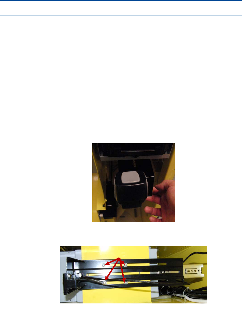
Component Procedures PAT Technical Manual
6-4 Confidential & Proprietary
6.2.2 Replacing the Wireless Barcode Reader (BCR)
To replace the barcode reader, perform the following:
1. Shut down the terminal.
2. Wait for the terminal relay to shutdown.
NOTE: You will hear five clicks as the terminal relay shuts down.
3. After the terminal relay shuts down, disconnect all power from the terminal.
4. Open the PAT:
a. Insert the red key into the lower keyhole on the side panel and turn the key.
b. Lift the PCT door handle on the side panel.
c. Open the PCT door.
5. Turn the thumbscrew counter-clockwise to release the rear panel.
6. Pull out BCR and remove BCR unit.
Figure 35: Bar Code Reader
7. Remove the four screws, washers, spacers, and spring securing the BCR Bracket.
Figure 36: Four Screws
Thumbscrew
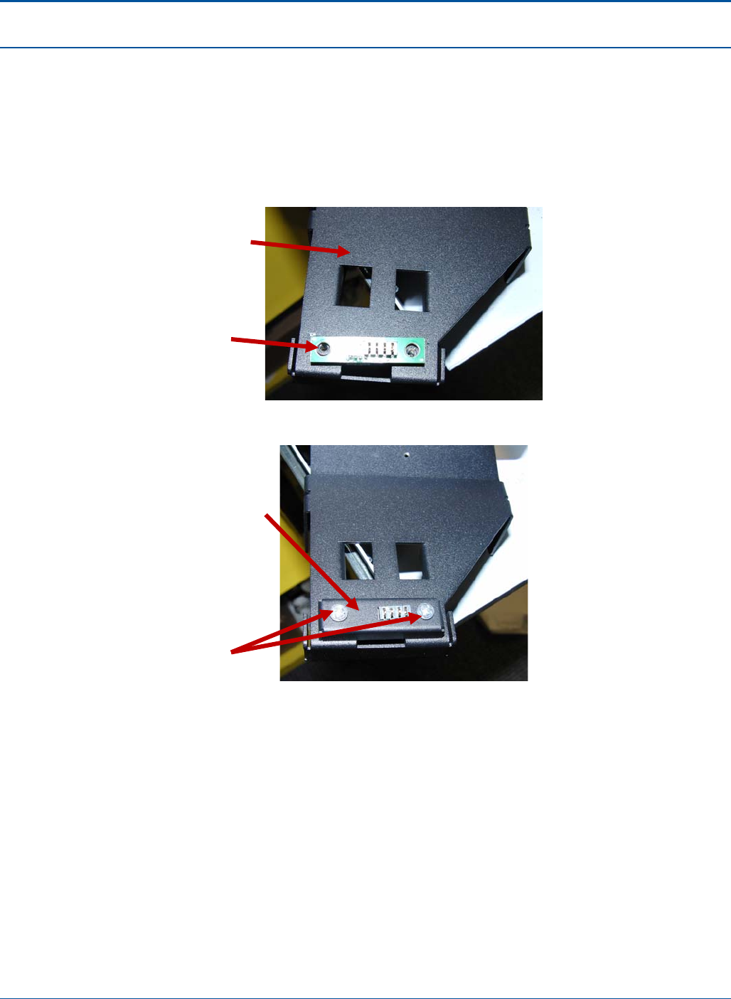
PAT Technical Manual Component Procedures
Confidential & Proprietary 6-5
8. Cut or remove BCR cable.
9. Route new BCR cable, CA05-0584-01, through scanner tray.
10. Attach BCR cable, CA05-0584-01 to BCR PCB, PA20-0363.
11. Attach PA20-0363 and cover, CV30-0053-01, to new BCR Bracket, BR30-0317
using two screws SC74-0008. Secure cable with tie wrap, TW60-0001 to hole on
BR30-0317.
Figure 37: New BCR Bracket
Figure 38: New BCR Bracket Screws
12. Remove plastic BCR cradle, BR20-0016, from the old metal bracket.
BR30-0317
PA20-0363,
note position
of contacts.
CV30-0053-01
SC74-0008
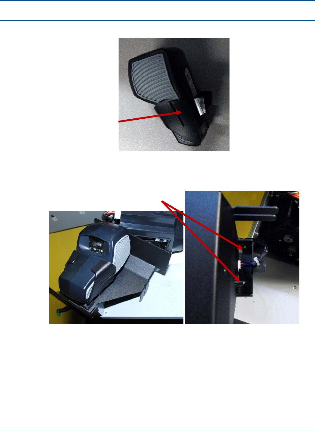
Component Procedures PAT Technical Manual
6-6 Confidential & Proprietary
13. Place BCR in BCR cradle, BR20-0016.
Figure 39: BCR Cradle
14. Attach BCR in BCR cradle to new BCR bracket, BR30-0317. Make sure that tabs
on BR20-0016 snap into place on BR30-0317.
Figure 40: Attaching BCR Cradle
15. Pull out scanner tray on terminal and remove scanner using the two thumbscrews
on the bottom of the tray. Set the scanner in the rear of the tray. There is no need
to unplug the scanner.
BR20-0016
Tabs snapped into
p
lace on BR30-0317
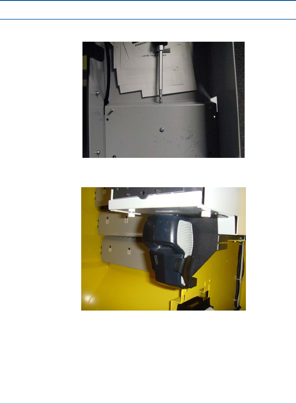
PAT Technical Manual Component Procedures
Confidential & Proprietary 6-7
16. Attach BCR assembly to the underside of the scanner tray using the two screws,
SC73-0004.
Figure 41: Attaching BCR Cradle to Scanner Tray
17. Replace scanner and secure with the two thumbscrews.
Figure 42: Attached BCR Cradle
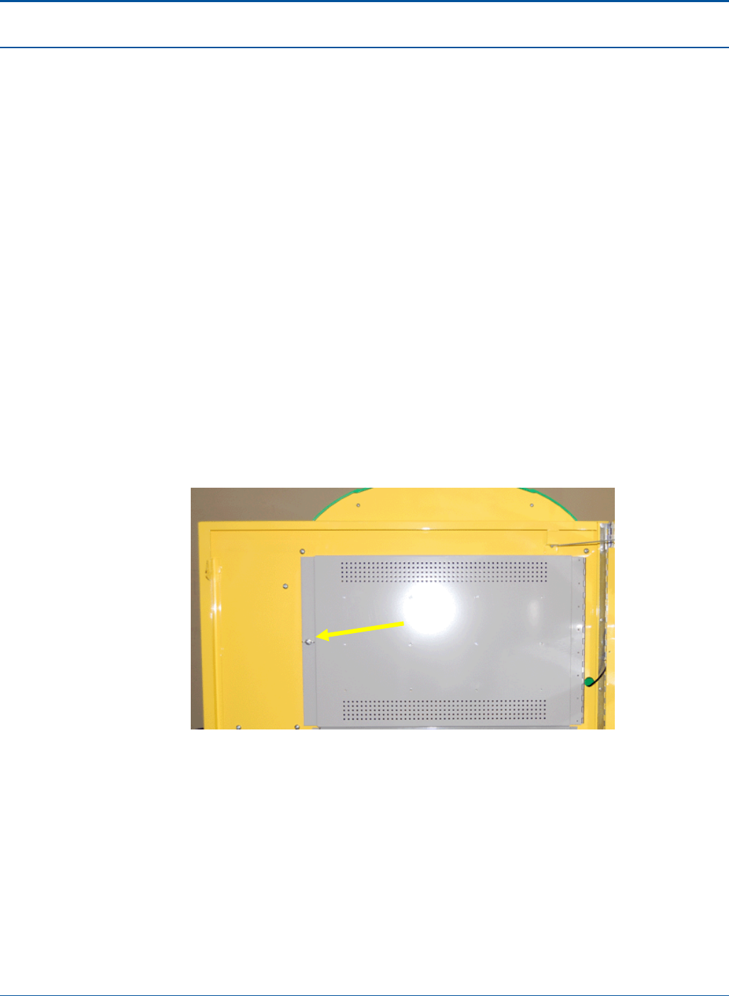
Component Procedures PAT Technical Manual
6-8 Confidential & Proprietary
6.3 Front Advertisement Assembly
The Front Advertisement Assembly consists of three light panels.
6.3.1 Removing the Front Advertisement Lights
To remove the front advertising lights, perform the following:
18. Shut down the terminal.
19. Wait for the terminal relay to shutdown.
NOTE: You will hear five clicks as the terminal relay shuts down.
20. After the terminal relay shuts down, disconnect all power from the terminal.
21. Open the PAT:
d. Insert the red key into the lower keyhole on the side panel and turn the key.
e. Lift the PCT door handle on the side panel.
f. Open the PCT door.
22. Turn the thumbscrew counter-clockwise to release the rear panel.
Figure 43: Front Advertisement Assembly – Rear Cover closed
23. Unplug the two (2) cables from each side of the light panel.
Thumbscrew
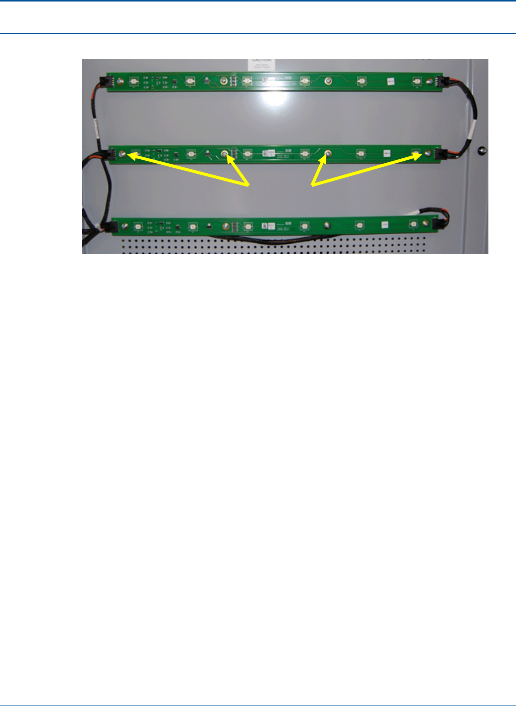
PAT Technical Manual Component Procedures
Confidential & Proprietary 6-9
24. Remove the four (4) screws from light panel.
Figure 44: Light Panel
25. To replace the light panel, perform the steps above in reverse.
6.3.2 Removing the Front Advertisement Power Supply
To remove the front advertisement power supply, perform the following:
1. Shut down the terminal.
2. Wait for the terminal relay to shutdown.
NOTE: You will hear five clicks as the terminal relay shuts down.
3. After the terminal relay shuts down, disconnect all power from the terminal.
4. Open the PAT:
a. Insert the red key into the lower keyhole on the side panel and turn the key.
b. Lift the PCT door handle on the side panel.
c. Open the PCT door.
Screw
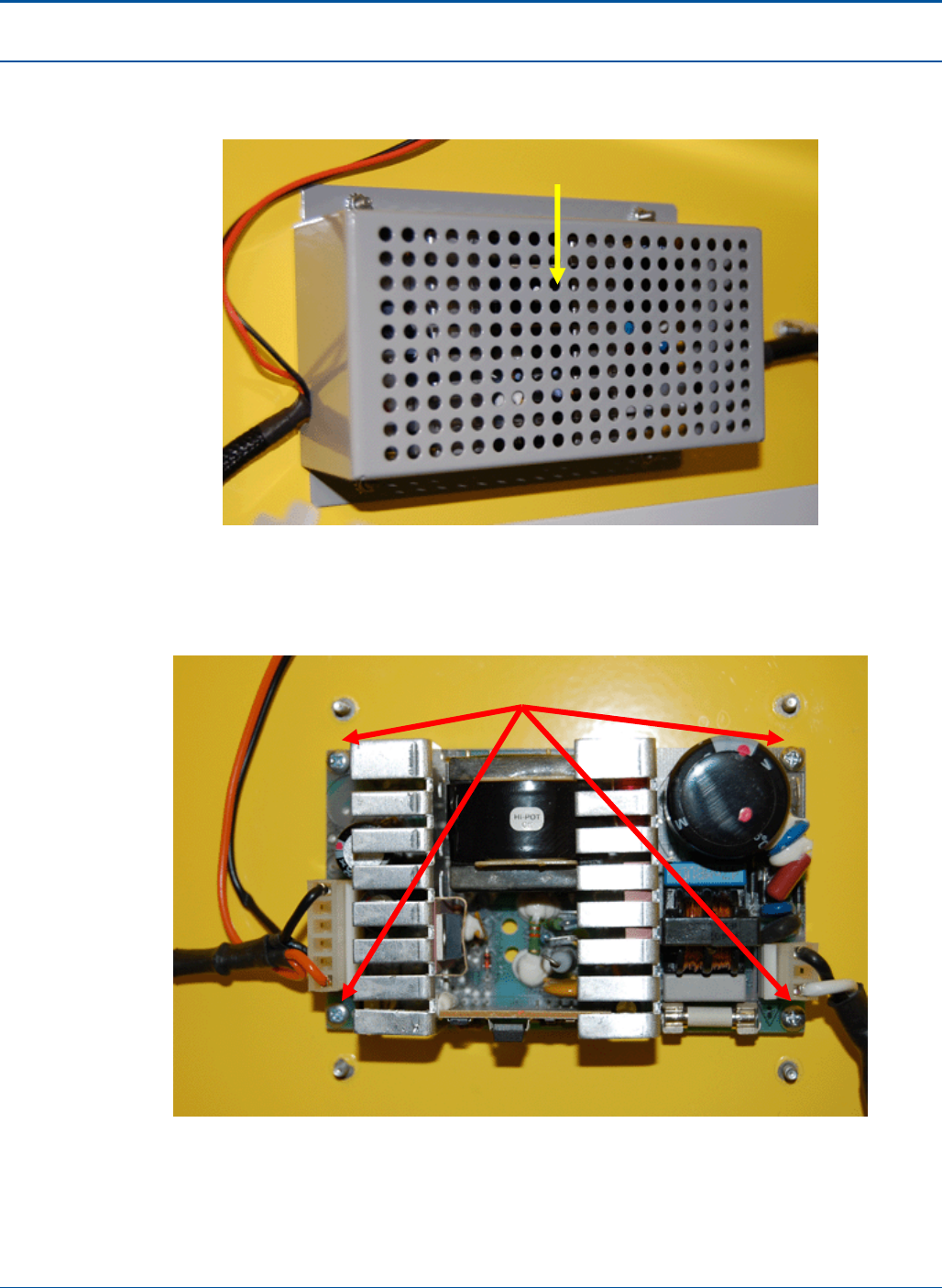
Component Procedures PAT Technical Manual
6-10 Confidential & Proprietary
5. On the upper left of the terminal, remove the Front Advertisement Assembly -
Power Supply Cover.
Figure 45: Front Advertisement Assembly - Power Supply Cover attached
6. Unplug the two (2) cables from the power supply.
7. Remove the four (4) screws holding the power supply to the terminal chassis.
Figure 46: Front Advertisement Assembly - Power Supply
8. To replace the power supply, perform the steps above in reverse.
Power Su
pp
l
y
Screw
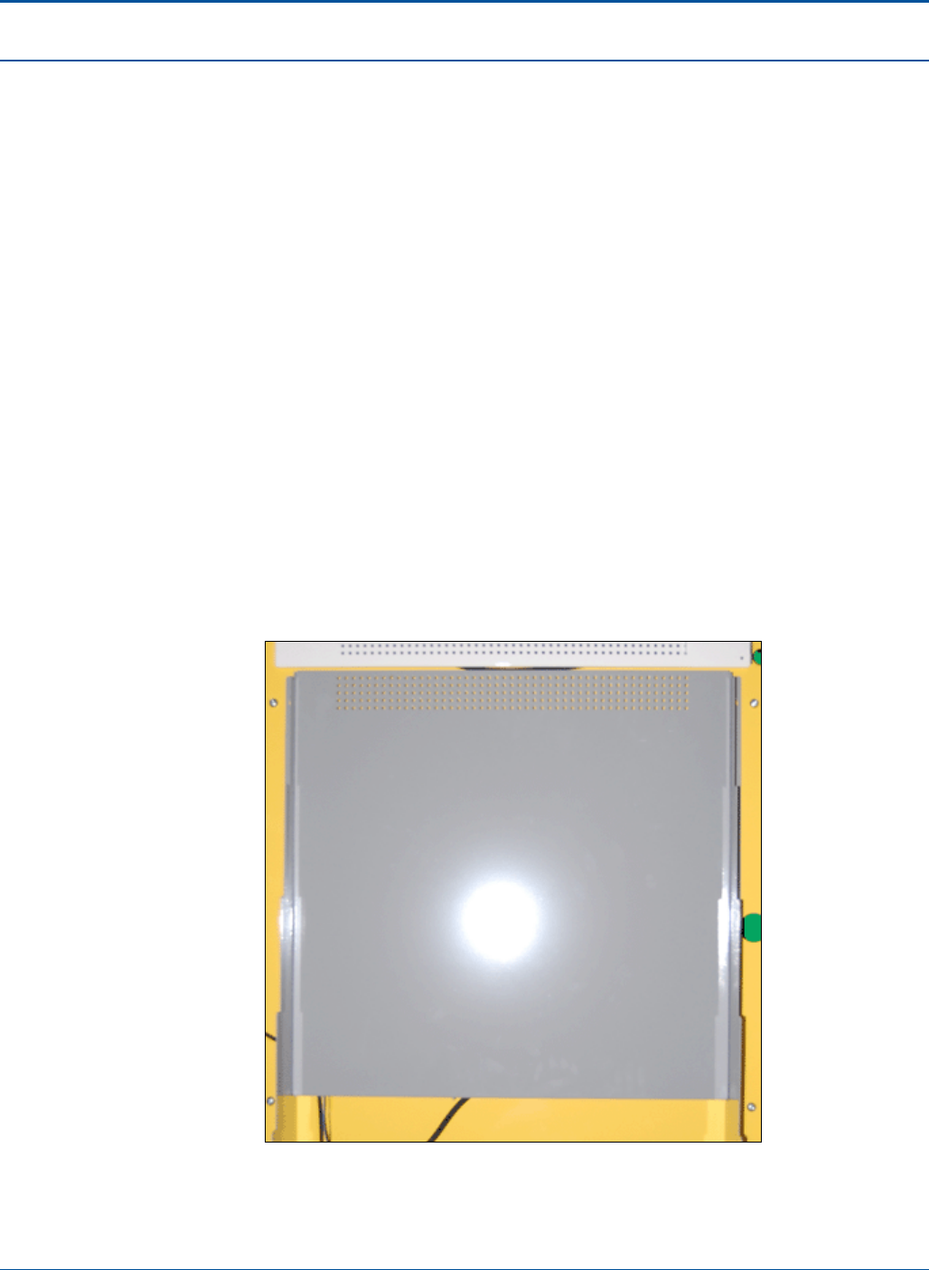
PAT Technical Manual Component Procedures
Confidential & Proprietary 6-11
6.4 Display Assembly
The Touch Screen Display allows the player to purchase on-line and instant game
tickets.
6.4.1 Removing the Display
To replace the terminal display, perform the following:
1. Shut down the terminal.
2. Wait for the terminal relay to shutdown.
NOTE: You will hear five clicks as the terminal relay shuts down.
3. After the terminal relay shuts down, disconnect all power from the terminal.
4. Open the PAT:
a. Insert the red key into the lower keyhole on the side panel and turn the key.
b. Lift the PCT door handle on the side panel.
c. Open the PCT door.
5. On the inside of the front door, remove the Display Assembly cover.
Figure 47: Display Assembly - Rear Cover
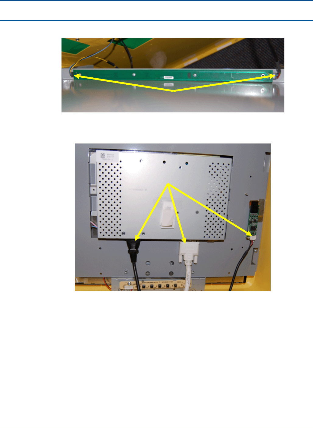
Component Procedures PAT Technical Manual
6-12 Confidential & Proprietary
6. Unplug the two (2) cables from the dispenser tray light.
Figure 48: Dispenser Tray Light
7. Unplug the three (3) cables from the display.
Figure 49: Display Assembly cables
Power Su
pp
l
y
Dis
p
la
y
Assembl
y
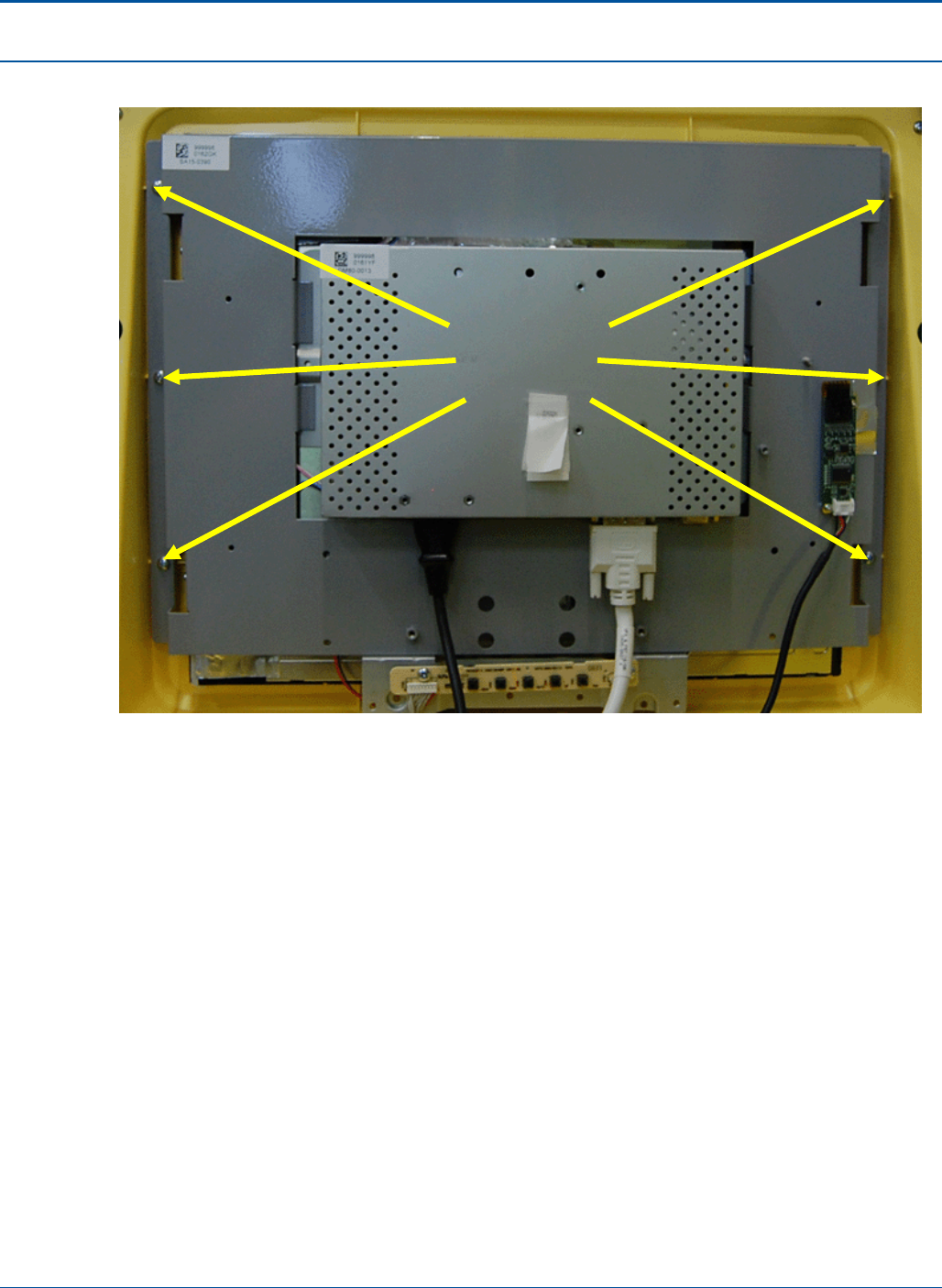
PAT Technical Manual Component Procedures
Confidential & Proprietary 6-13
8. Remove the six (6) screws attaching the display bracket to the terminal.
Figure 50: Display Assembly - Rear Bracket Attached
Screw
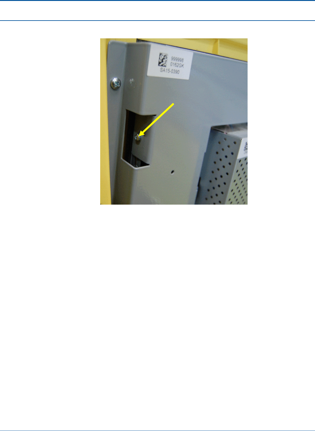
Component Procedures PAT Technical Manual
6-14 Confidential & Proprietary
9. Remove the four (4) screws attaching the display to the display bracket.
Figure 51: Display Assembly - Rear Bracket Attached
10. Remove the display from the display bracket.
11. To replace the display, perform the steps above in reverse.
Dis
p
la
y
Bracket
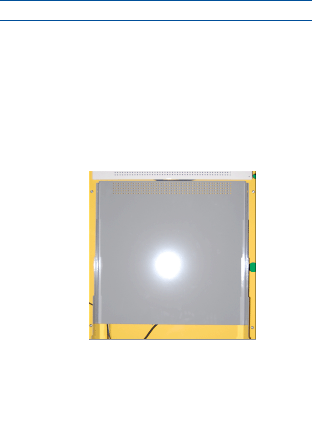
PAT Technical Manual Component Procedures
Confidential & Proprietary 6-15
6.4.2 Adding a Second Monitor
To replace the terminal display, perform the following:
1. Shut down the terminal.
2. Wait for the terminal relay to shutdown.
NOTE: You will hear five clicks as the terminal relay shuts down.
3. After the terminal relay shuts down, disconnect all power from the terminal.
4. Open the PAT:
a. Insert the red key into the lower keyhole on the side panel and turn the key.
b. Lift the PCT door handle on the side panel.
c. Open the PCT door.
5. On the inside of the front door, remove the Display Assembly cover.
Figure 52: Display Assembly - Rear Cover
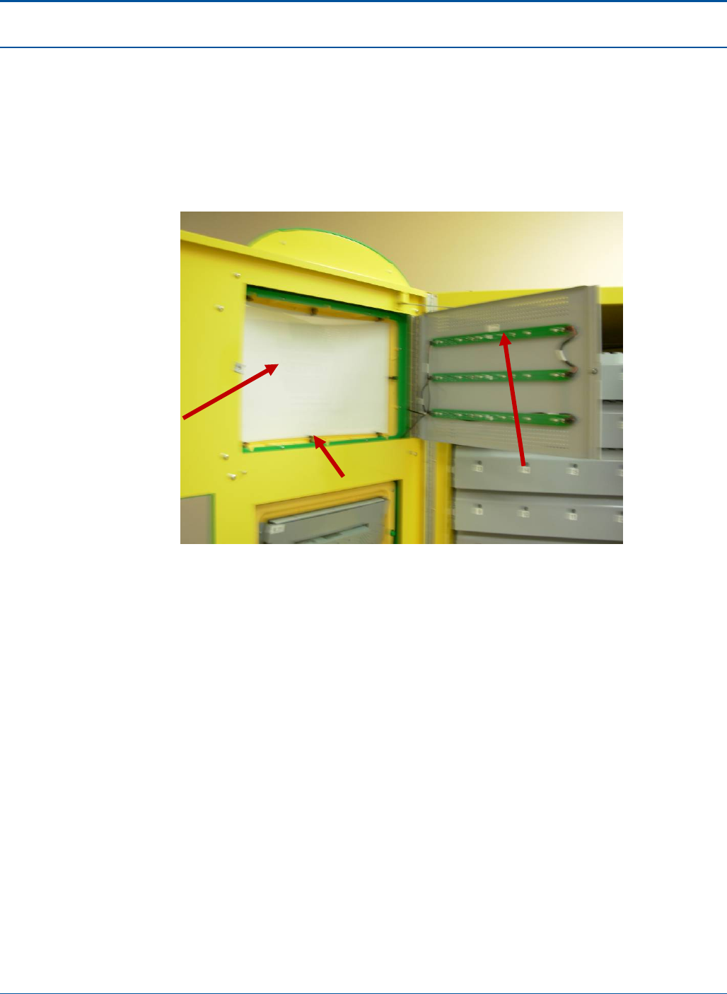
Component Procedures PAT Technical Manual
6-16 Confidential & Proprietary
6. Pull on Handle HK20-0014 and twist to release the Display panel cover PL30-
0020.
7. Take out 1 pc of the Display Panel Cover PL30-0020 and Advertising Display
LG30-0082.
8. Disconnect and Remove the 3 LED strips PA20-0338.
9. Unplug the two (2) cables from the dispenser tray light.
Figure 53: Display Assembly - Inside
10. Remove existing screws SC58-0003 securing BZ20-0052.
LG30-0082
Advertising
Panel
PA20-0338
ASSY, PCB, Interface,
LUMI-LED Bar
PL30-0020
Panel (Sheet-Fab) Plate
Advertising Display
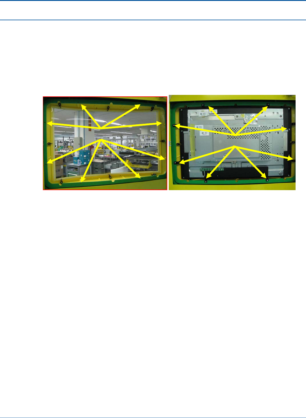
PAT Technical Manual Component Procedures
Confidential & Proprietary 6-17
11. With another person holding the Bezel from front, the Display sub-assembly is
mounted as shown with 8 new screws SC58-0009.
12. Remove 8 screws SC58-0003 to detach BZ20-0052 from the Front Bezel.
NOTE: Ensure the Clear Panel is firmly secured to the Front Bezel all round the
periphery.
NOTE: Ensure both the LCD Display surface and the Clear Panel is clean, and
free of stains/ dirt, before assembly.
Figure 54: Display Assembly Screws
8 Screws 8 Screws
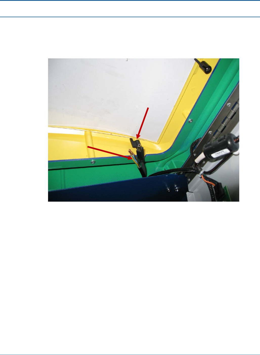
Component Procedures PAT Technical Manual
6-18 Confidential & Proprietary
13. Insert CA90-0177 through the hole in the bezel from underneath as shown.
14. Start CA60-0109 (CA60-0007 if available) by inserting at the bottom of the door
and work up to the opening in the bezel.
15. Secure CA70-0030 to CU90-0030. Note the orientation.
Figure 55: Display Assembly Cables
CA90-0177 CABLE, OEM,
USB 10 FT (3M), A-MINIB
CA60-0109 (CA60-0007 if available)
CORD, POWER,118",OPEN
END,NEMA5-15P PLUG
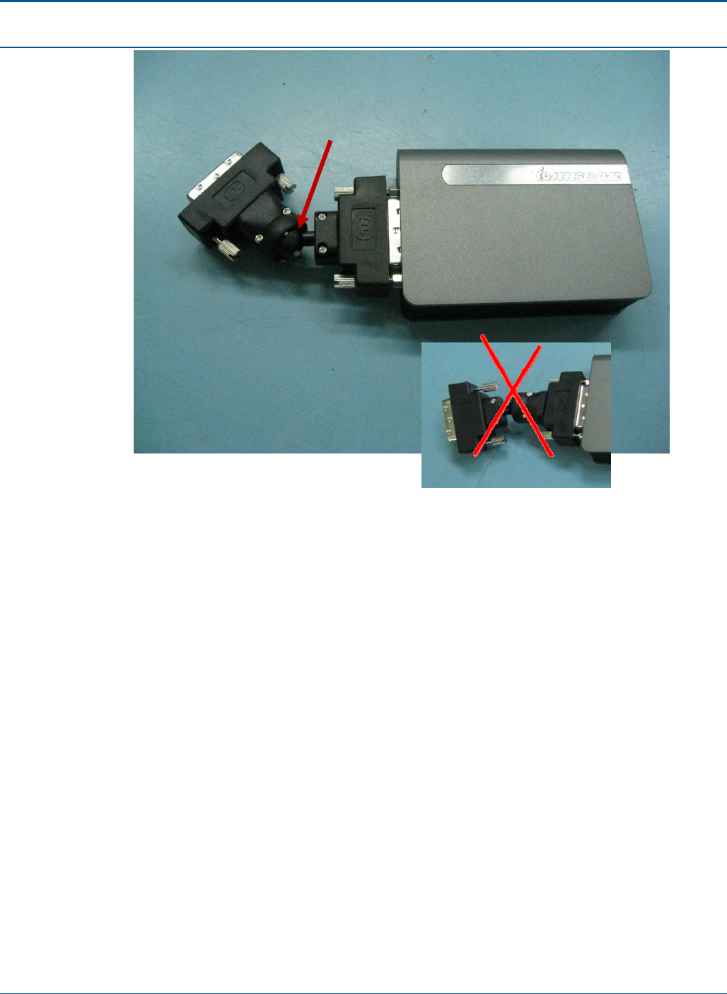
PAT Technical Manual Component Procedures
Confidential & Proprietary 6-19
Figure 56: Display Connection
Ball this end
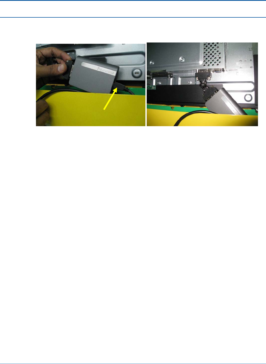
Component Procedures PAT Technical Manual
6-20 Confidential & Proprietary
16. Connect other end of DVI CARD to the mini-USB.
17. Attach the assembly to the Display DVI port.
Figure 57: DVI Card
18. Attach Connector CN85-0045 to Power Cable CA60-0109 (CA60-0007 if available)
and connect to Display power input.
19. Route the Cable of CA60-0109 (CA60-0007 if available) to CN84-0045 as shown.
USB Connection
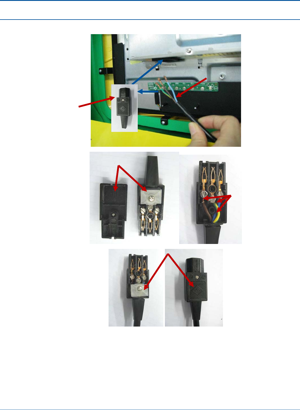
PAT Technical Manual Component Procedures
Confidential & Proprietary 6-21
20. Connect Power Connector to Display power port.
Figure 58: Power Connector
21. Route the other end of Power cable neatly through front door cable harness.
22. Route the other end of the USB cable through the opening near the top of the door
and along the top of the main cabinet back to the E-Tray.
23. Route USB cable along top of cabinet to right side of inner wall and then through
opening in back to E-Tray.
CN85-0045
CONN,
POWER,PLUG
115VAC SCREW
TERMINALS
Live - Brown
Neutral - Blue
Ground- Yellow/ Green
Dismantle 2 covers Route cables,
Live - Brown
Nuetral - Blue
Ground- Yellow/ Green
Assemble back covers
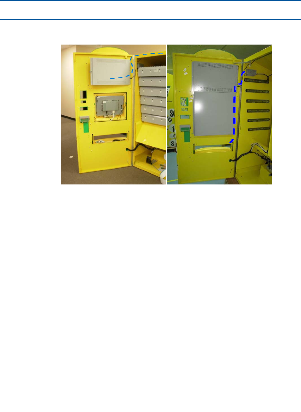
Component Procedures PAT Technical Manual
6-22 Confidential & Proprietary
24. Change CA05-0543-01, 24V DC supply cable and connect to PA20-0338 (LED
PCBA) in ticket chute and top of cabinet and Power Supply as shown.
Figure 59: DC Supply Cable
25. Connect the Power cable to the "Surge only" end of the UPS.
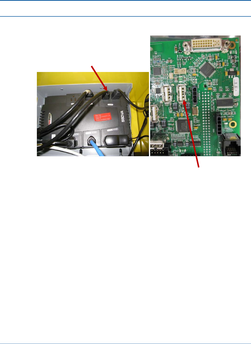
PAT Technical Manual Component Procedures
Confidential & Proprietary 6-23
26. Route the USB neatly to the back of the E-Tray and connect to the USB port
shown.
Figure 60: USB Cable Connection
CA60-0109 (CA60-0007 if
available) connect here
CA90-0160 USB CABLE-
connect here
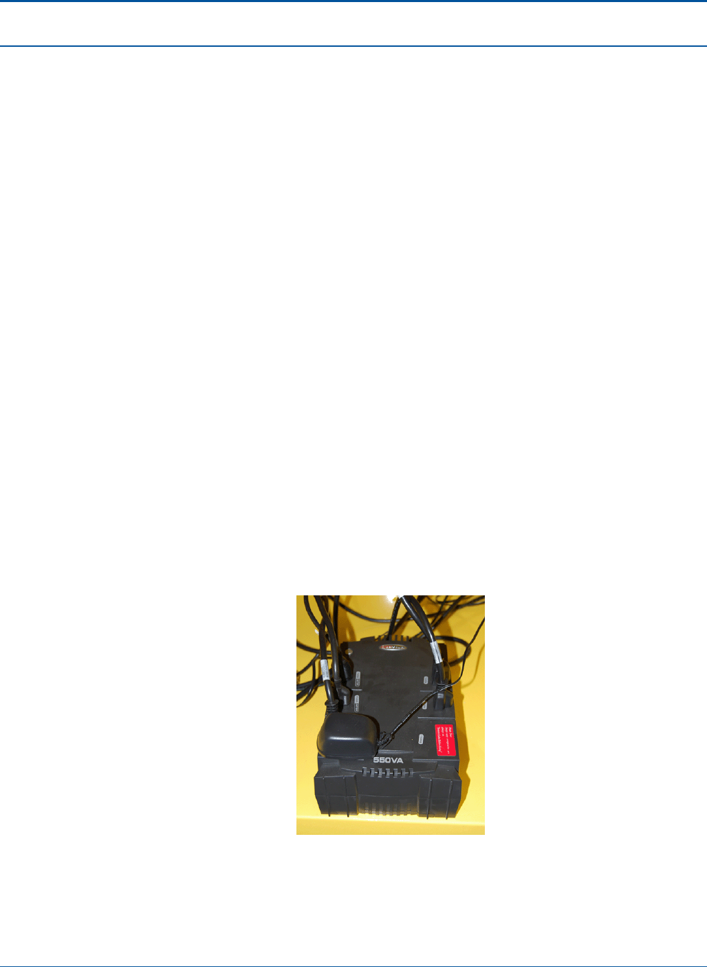
Component Procedures PAT Technical Manual
6-24 Confidential & Proprietary
6.5 Electronics Tray
The sections below provide the procedures for replacing the following PCT components:
• UPS Power Supply
• PC Power Supply
• Interface Board
• Mother Board
• Hard Drive
6.5.1 UPS Power Supply
To remove the UPS power supply, perform the following:
1. Shut down the terminal.
2. Wait for the terminal relay to shutdown.
NOTE: You will hear five clicks as the terminal relay shuts down.
3. After the terminal relay shuts down, disconnect all power from the terminal.
4. Open the PAT:
a. Insert the red key into the lower keyhole on the side panel and turn the key.
b. Lift the PCT door handle on the side panel.
c. Open the PCT door.
5. Disconnect all of the plugs connected to the UPS power supply.
Figure 61: UPS Power Supply
6. Remove the UPS power supply.
7. To replace the UPS power supply, perform the steps above in reverse.
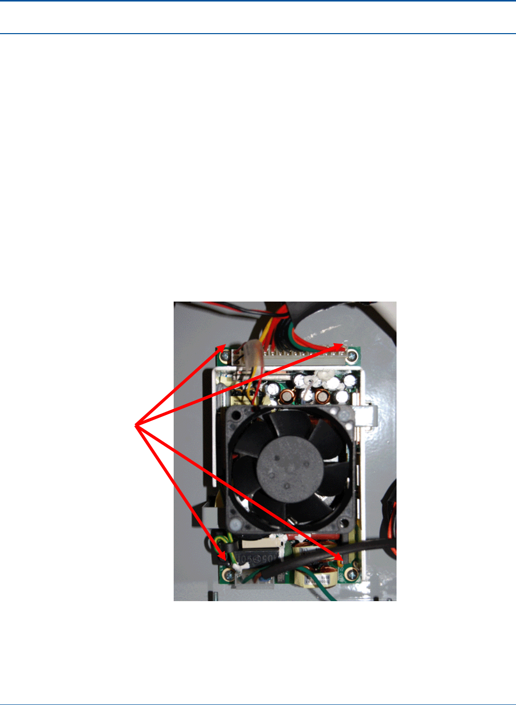
PAT Technical Manual Component Procedures
Confidential & Proprietary 6-25
6.5.2 PC Power Supply Unit
To remove the PC power supply, perform the following:
1. Shut down the terminal.
2. Wait for the terminal relay to shutdown.
NOTE: You will hear five clicks as the terminal relay shuts down.
3. After the terminal relay shuts down, disconnect all power from the terminal.
4. Open the PAT:
a. Insert the red key into the lower keyhole on the side panel and turn the key.
b. Lift the PCT door handle on the side panel.
c. Open the PCT door.
5. Disconnect all of the plugs connected to the PC power supply.
6. Remove the four (4) mounting screws.
Figure 62: PC Power Supply
7. Remove the PC power supply.
8. To replace the PC power supply, perform the steps above in reverse.
Mounting
screws
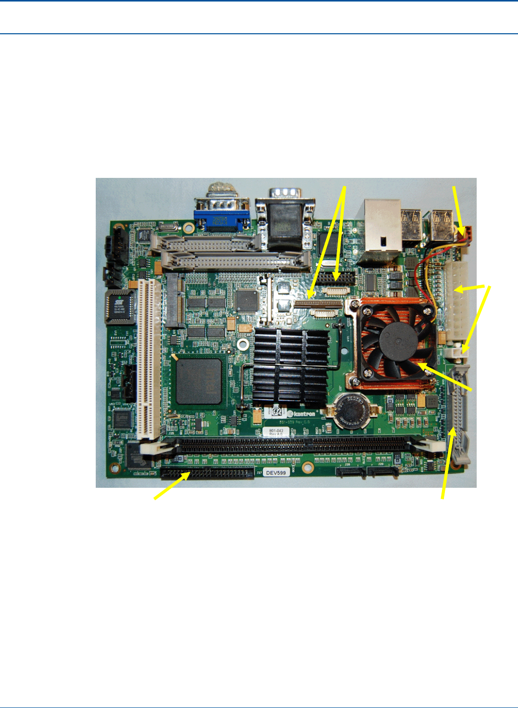
Component Procedures PAT Technical Manual
6-26 Confidential & Proprietary
6.5.3 Mother Board
The Mother Board is the master controller for the PCT terminal.
6.5.3.1 Identifying Mother Board Connections
The figure below identifies the location of selected cable connections on the Mother
Board.
Figure 63: Mother Board
Video cables Fan cable
Power
cables
Fan &
Process
PS/2 cable is
configured on the
34 pin connector
IDE cable
USC/Serial cable
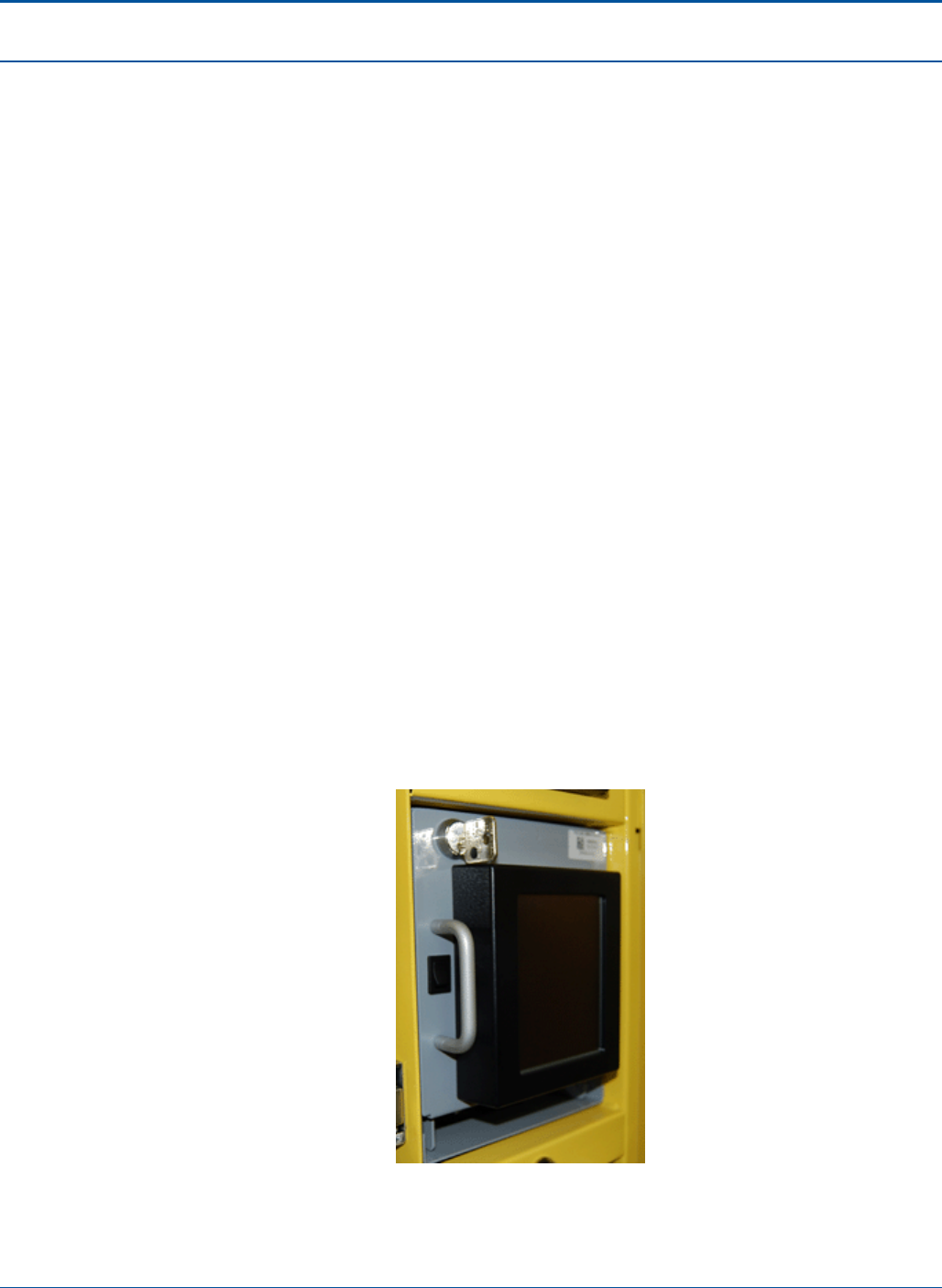
PAT Technical Manual Component Procedures
Confidential & Proprietary 6-27
6.5.3.2 Replacing the Mother Board
The objective of this section is to define the procedures for replacing the mother board in
the terminal. Following these procedures will help any individual accomplish this task
successfully.
Required Tools and Equipment
• 1 PCT Terminal
• 1 Replacement mother board
• 1 Tool (part number: TL90-0358-RH)
• Phillips screwdriver
To replace the mother board, perform the following:
1. Shut down the terminal.
2. Wait for the terminal relay to shutdown.
NOTE: You will hear five clicks as the terminal relay shuts down.
3. After the terminal relay shuts down, disconnect all power from the terminal.
4. Open the PAT:
a. Insert the red key into the lower keyhole on the side panel and turn the key.
b. Lift the PCT door handle on the side panel.
c. Open the PCT door.
5. Unlock the Electronics Tray by inserting the black key into the lock above the tray.
Figure 64: Black Key Inserted
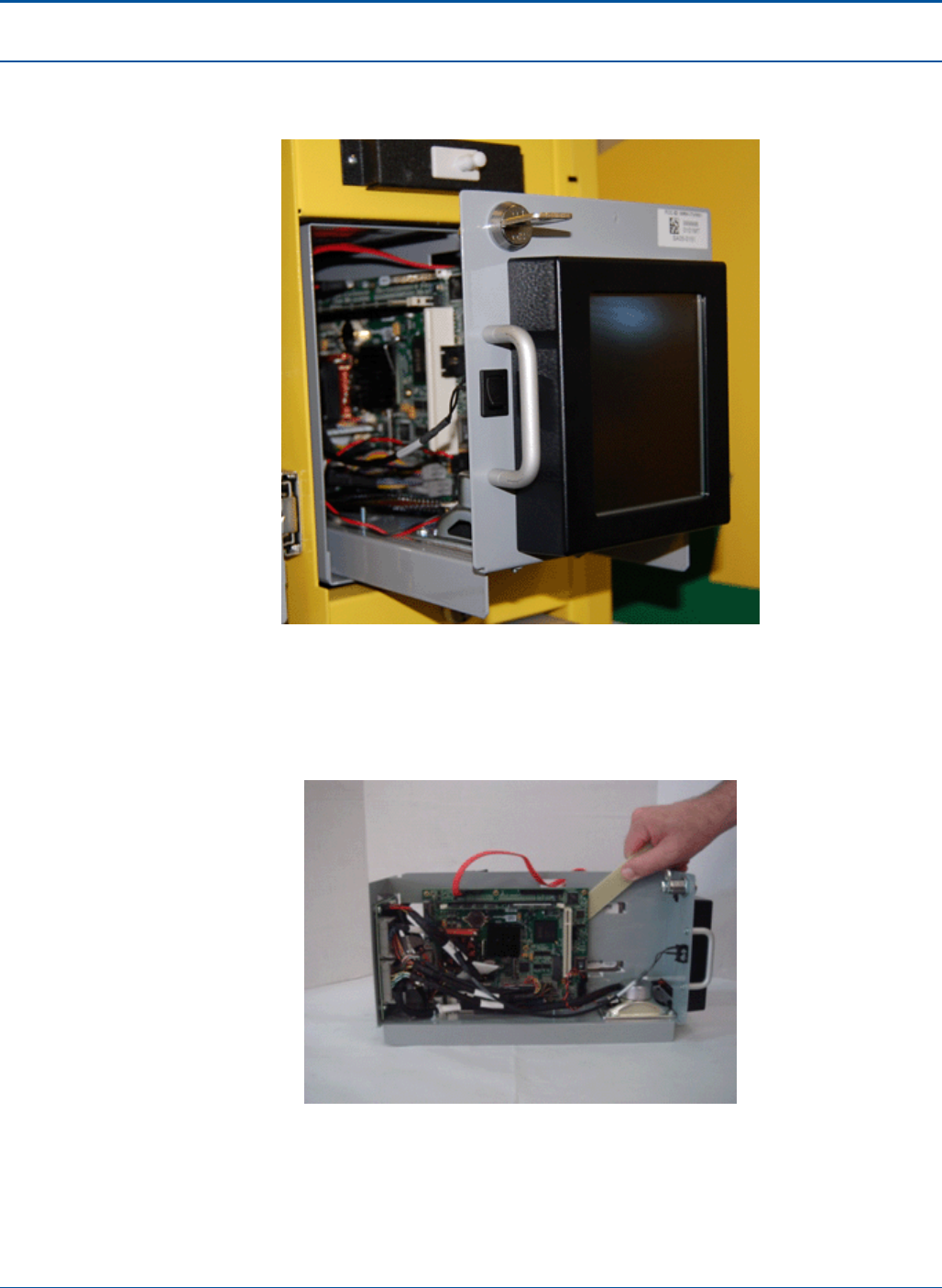
Component Procedures PAT Technical Manual
6-28 Confidential & Proprietary
6. Slide the Electronics Tray out of the Electronics Tray housing and place on a flat,
clear surface.
Figure 65: Removing the Electronics Tray
7. Remove the all cables from the mother board.
8. Use the tool (part number: TL90-0358-RH) to remove the motherboard from the
electronics tray.
Figure 66: Removing the Mother Board from the Electronics Tray
9. Carefully place the new mother board onto the electronics tray.
10. Re-attach all the cables to the mother board.
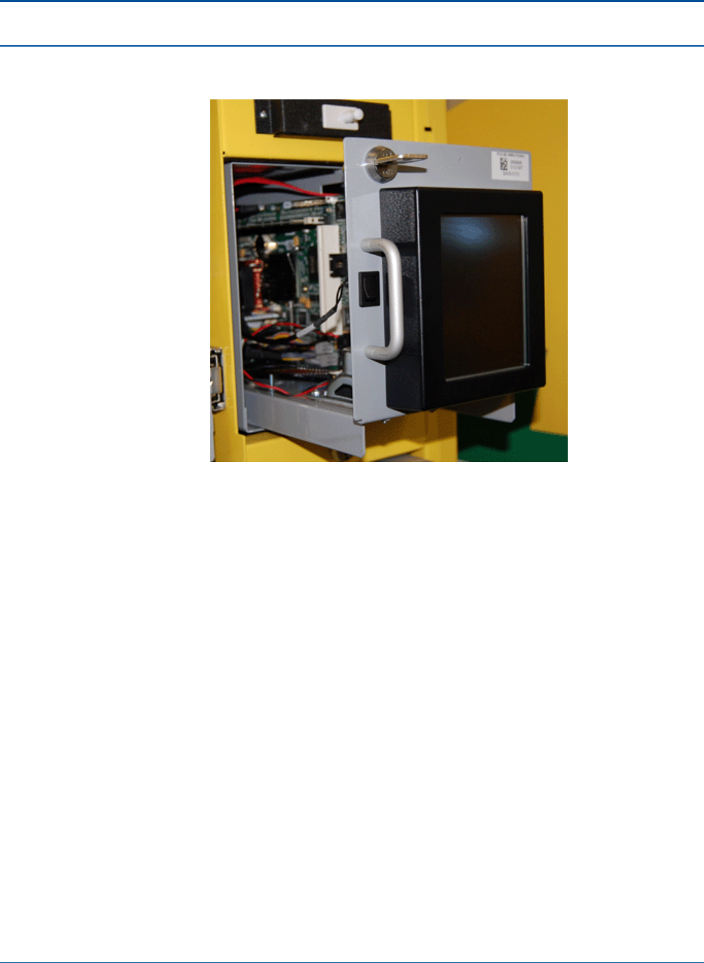
PAT Technical Manual Component Procedures
Confidential & Proprietary 6-29
11. After re-attaching all the cables, slide the electronics tray back into the electronics
tray housing.
Figure 67: Re-inserting the Electronics Tray
12. Lock the electronics tray and remove the black key from the lock above the tray.
13. Close the PAT:
a. Insert the red key into the lower keyhole on the side panel and turn the key.
b. Lift the PCT door handle on the side panel.
c. Close the PCT door.
14. Reconnect all power to the terminal.
15. Power up the terminal.

Component Procedures PAT Technical Manual
6-30 Confidential & Proprietary
6.5.4 Interconnect Board
The Interconnect Board is located in the Electronics Tray.
6.5.4.1 Replacing the Interconnect Board
The objective of this section is to define the procedures for replacing the interconnect
board in the PCT terminal. Following these procedures will help any individual
accomplish this task successfully.
Required Tools and Equipment
• 1 PCT Terminal
• 1 Replacement interconnect board
• 1 Tool
• Phillips screwdriver
To replace the interconnect board, perform the following:
1. Shut down the terminal.
2. Wait for the terminal relay to shutdown.
NOTE: You will hear five clicks as the terminal relay shuts down.
3. After the terminal relay shuts down, disconnect all power from the terminal.
4. Open the PAT:
a. Insert the red key into the lower keyhole on the side panel and turn the key.
b. Lift the PCT door handle on the side panel.
c. Open the PCT door.
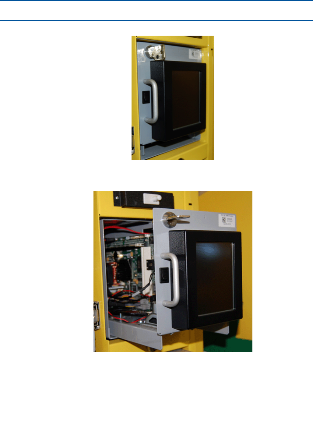
PAT Technical Manual Component Procedures
Confidential & Proprietary 6-31
5. Unlock the Electronics Tray by inserting the black key into the lock above tray.
Figure 68: Black Key Inserted
6. Slide the electronics tray out of the electronics tray housing.
Figure 69: Removing the Electronics Tray
7. Remove the all cables from the interconnect board.
8. Use the tool (part number: TL90-0358-RH) to remove the interconnect board from
the electronics tray.
9. Carefully place the new interconnect board onto the electronics tray.

Component Procedures PAT Technical Manual
6-32 Confidential & Proprietary
10. Re-attach all the cables to the interconnect board.
11. After re-attaching all the cables, slide the electronics tray back into the electronics
tray housing.
12. Lock the electronics tray and remove the black key from the lock above the tray.
13. Close the PAT:
a. Insert the red key into the lower keyhole on the side panel and turn the key.
b. Lift the PCT door handle on the side panel.
c. Close the PCT door.
14. Reconnect all power to the terminal.
15. Power up the terminal.
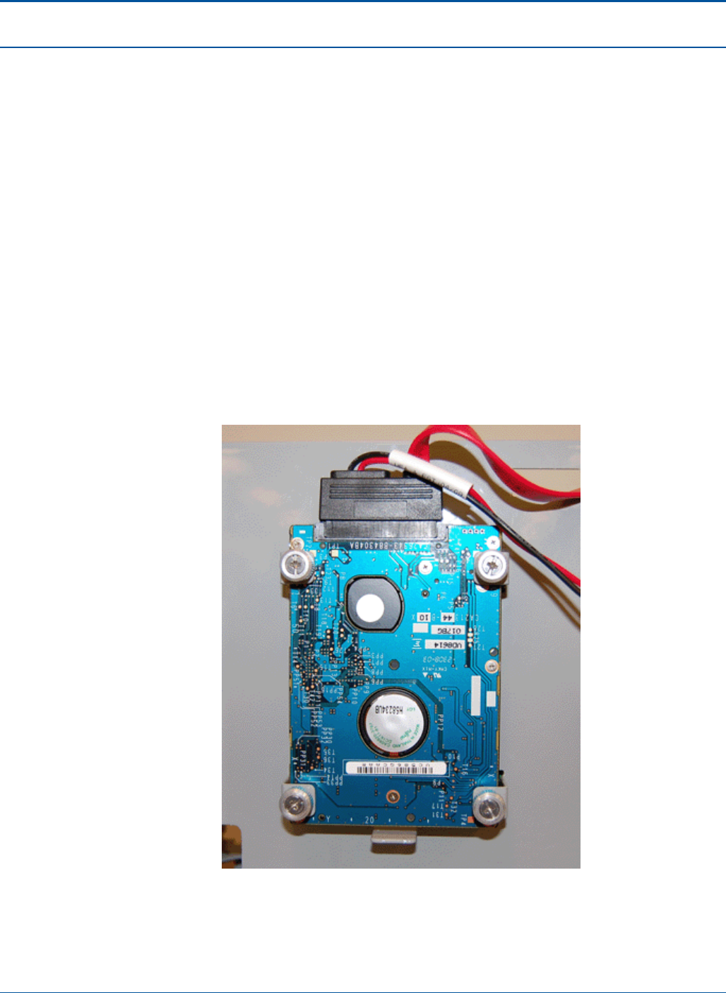
PAT Technical Manual Component Procedures
Confidential & Proprietary 6-33
6.5.5 Hard Drive
The Hard Drive is located in the Electronics Tray.
To replace the hard drive, perform the following:
1. Shut down the terminal.
2. Wait for the terminal relay to shutdown.
NOTE: You will hear five clicks as the terminal relay shuts down.
3. After the terminal relay shuts down, disconnect all power from the terminal.
4. Open the PAT:
a. Insert the red key into the lower keyhole on the side panel and turn the key.
b. Lift the PCT door handle on the side panel.
c. Open the PCT door.
5. Disconnect the wire from the hard drive.
Figure 70: Hard Drive
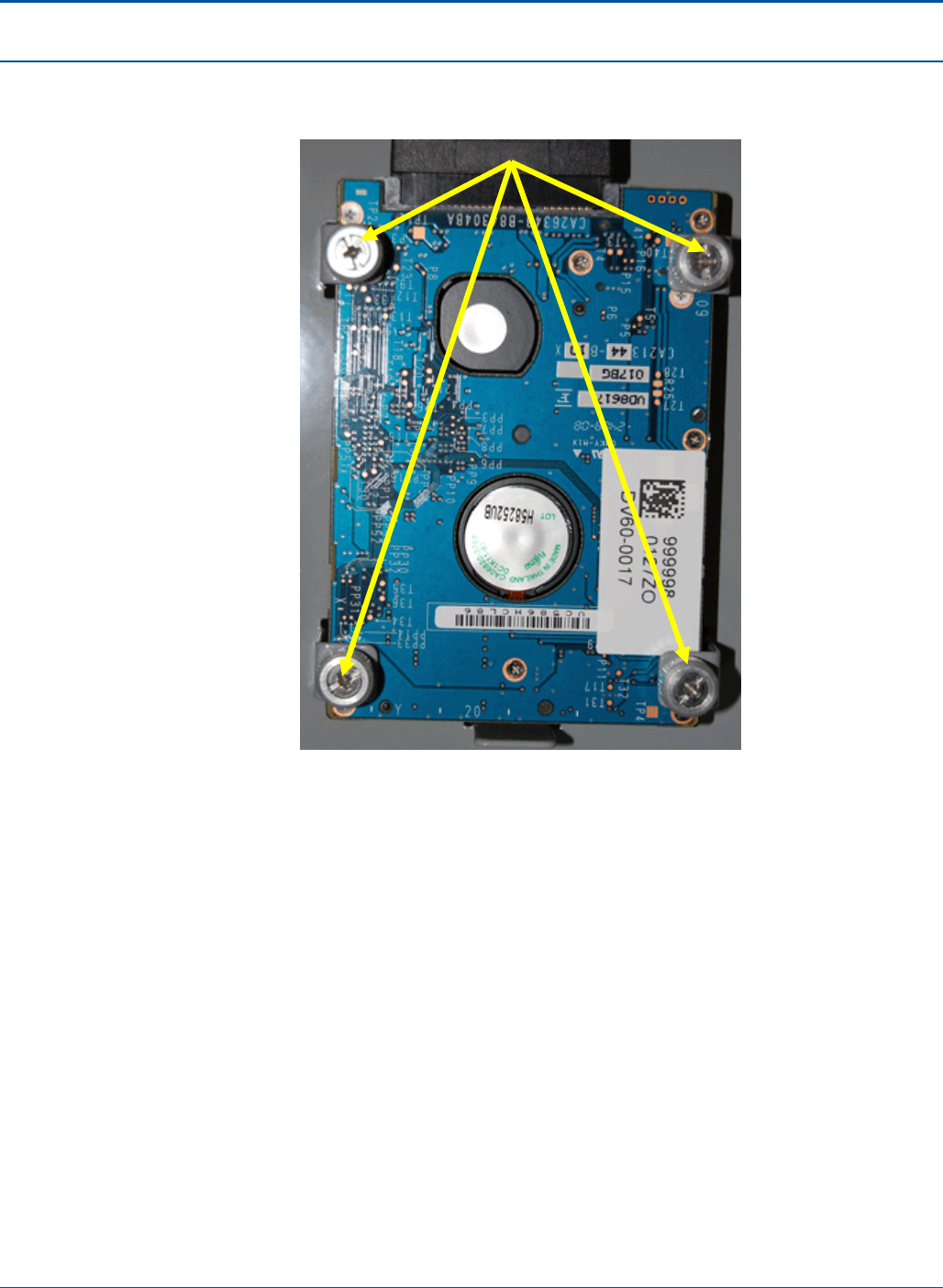
Component Procedures PAT Technical Manual
6-34 Confidential & Proprietary
6. Turn the four (4) thumbscrews counter clockwise and pull the hard drive up to
remove it from the terminal.
Figure 71: Hard Drive Thumbscrews
7. To replace the hard drive, perform the steps above in reverse.
Thumbscrew
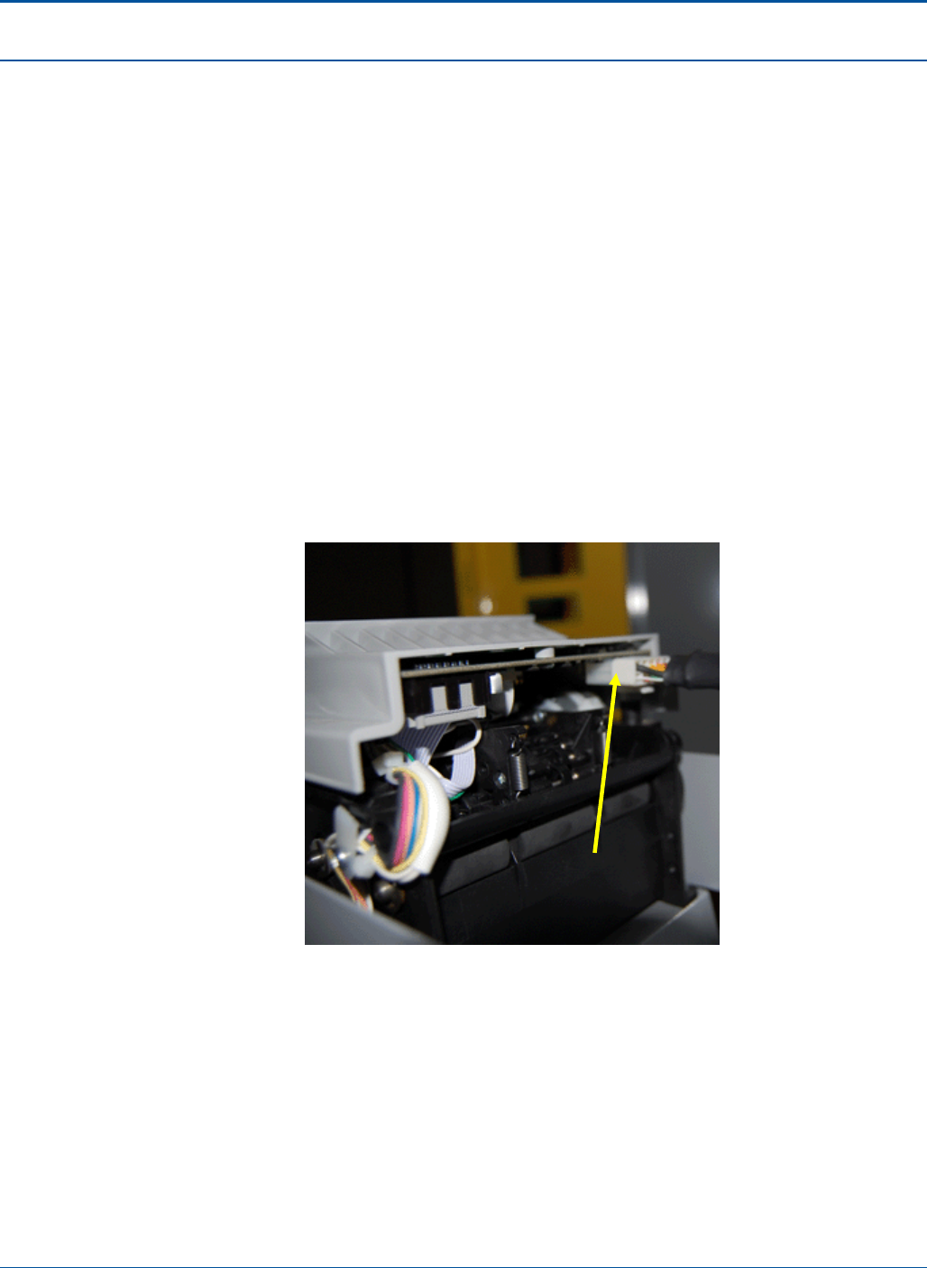
PAT Technical Manual Component Procedures
Confidential & Proprietary 6-35
6.5.6 Document Scanner Assembly
To remove the document scanner, perform the following:
1. Shut down the terminal.
2. Wait for the terminal relay to shutdown.
NOTE: You will hear five clicks as the terminal relay shuts down.
3. After the terminal relay shuts down, disconnect all power from the terminal.
4. Open the PAT:
a. Insert the red key into the lower keyhole on the side panel and turn the key.
b. Lift the PCT door handle on the side panel.
c. Open the PCT door.
5. Pull out the document scanner tray.
6. Remove the printer cable from the back of the document scanner.
Figure 72: Document Scanner Cable
7. Remove the four (4) screws that attach the document scanner to the document
scanner tray.
8. Replace the document scanner.
9. To replace the display, perform the steps above in reverse.
Document Scanner Cable
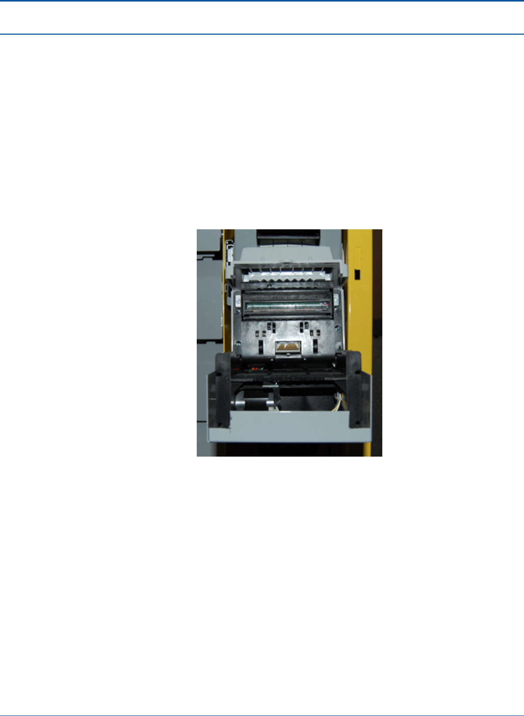
Component Procedures PAT Technical Manual
6-36 Confidential & Proprietary
6.5.7 Clearing a Paper Jam
To clear a paper jam, perform the following:
1. Open the PAT:
a. Insert the red key into the lower keyhole on the side panel and turn the key.
b. Lift the PCT door handle on the side panel.
c. Open the PCT door.
2. Pull out the document scanner tray.
3. Lift the lid of the document scanner.
Figure 73: Document Scanner – Open
4. Remove the jammed paper.
5. Close the lid of the document scanner.
6. Push the document scanner tray back into its original position.
7. Close and lock the PCT door.
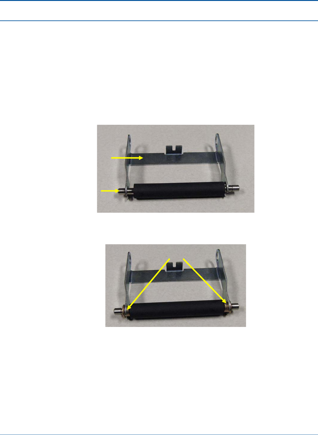
PAT Technical Manual Component Procedures
Confidential & Proprietary 6-37
6.5.8 Replacing the Assembly Roller
To replace the assembly roller, perform the following:
1. Open the PAT:
a. Insert the red key into the lower keyhole on the side panel and turn the key.
b. Lift the PCT door handle on the side panel.
c. Open the PCT door.
2. Place the assemble roller, RL10-0019, into the bracket, BR30-0265.
Figure 74: Assembly Roller and Bracket
3. Insert bearings (2X), BE70-0001, into the assembly.
Figure 75: Assembly Roller Bearings
BR30-0265
RL10-0019
BE70-0001
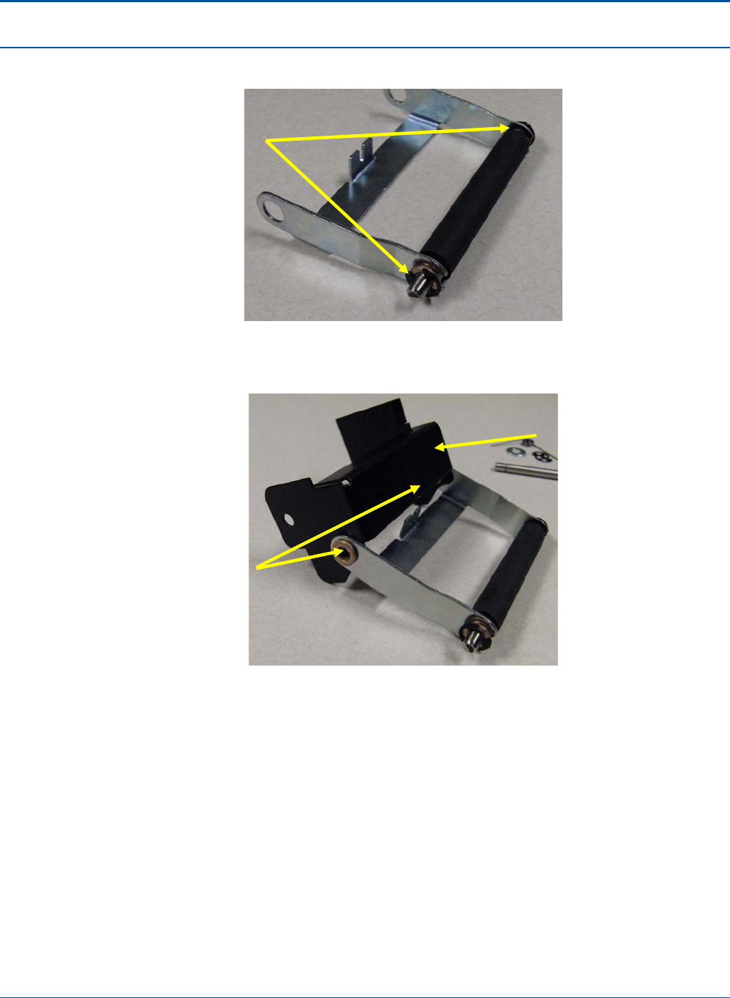
Component Procedures PAT Technical Manual
6-38 Confidential & Proprietary
4. Attach e-rings (2X), RR60-0007, to RL10-0019.
Figure 76: Assembly Roller Bearings
5. Attach assembly to bracket BR30-0341 by using two bearings, BE70-0001.
Figure 77: Assembly Roller Bearings
RR60-0007
BE70-0001
BR30-0341
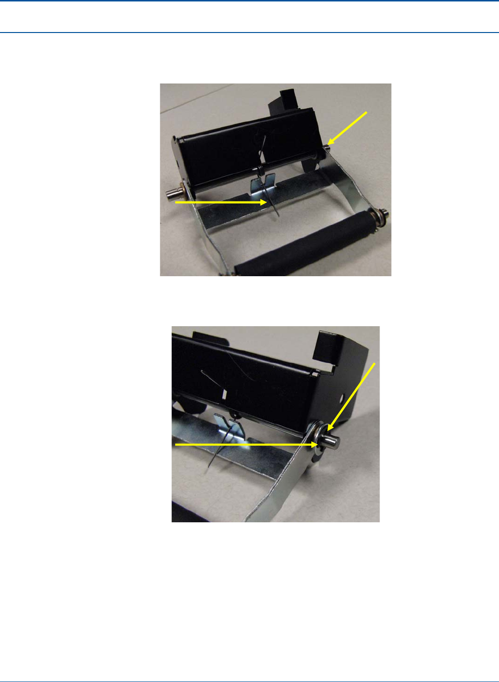
PAT Technical Manual Component Procedures
Confidential & Proprietary 6-39
6. Insert shaft, SH10-0035, through bearings installed in step 4. While inserting shaft,
position spring, SG80-0003, on shaft with spring arms in recesses of BR30-0341
and BR30-0265.
Figure 78: Assembly Roller Shaft and Spring
7. Insert washer, WA90-0138, onto end of shaft, SH10-0035.
Figure 79: Assembly Roller Washer
8. Secure shaft, SH10-0035 with two retaining rings, RR60-0007.
SG80-0003
SH10-0035
WA90-0138
WA90-0138
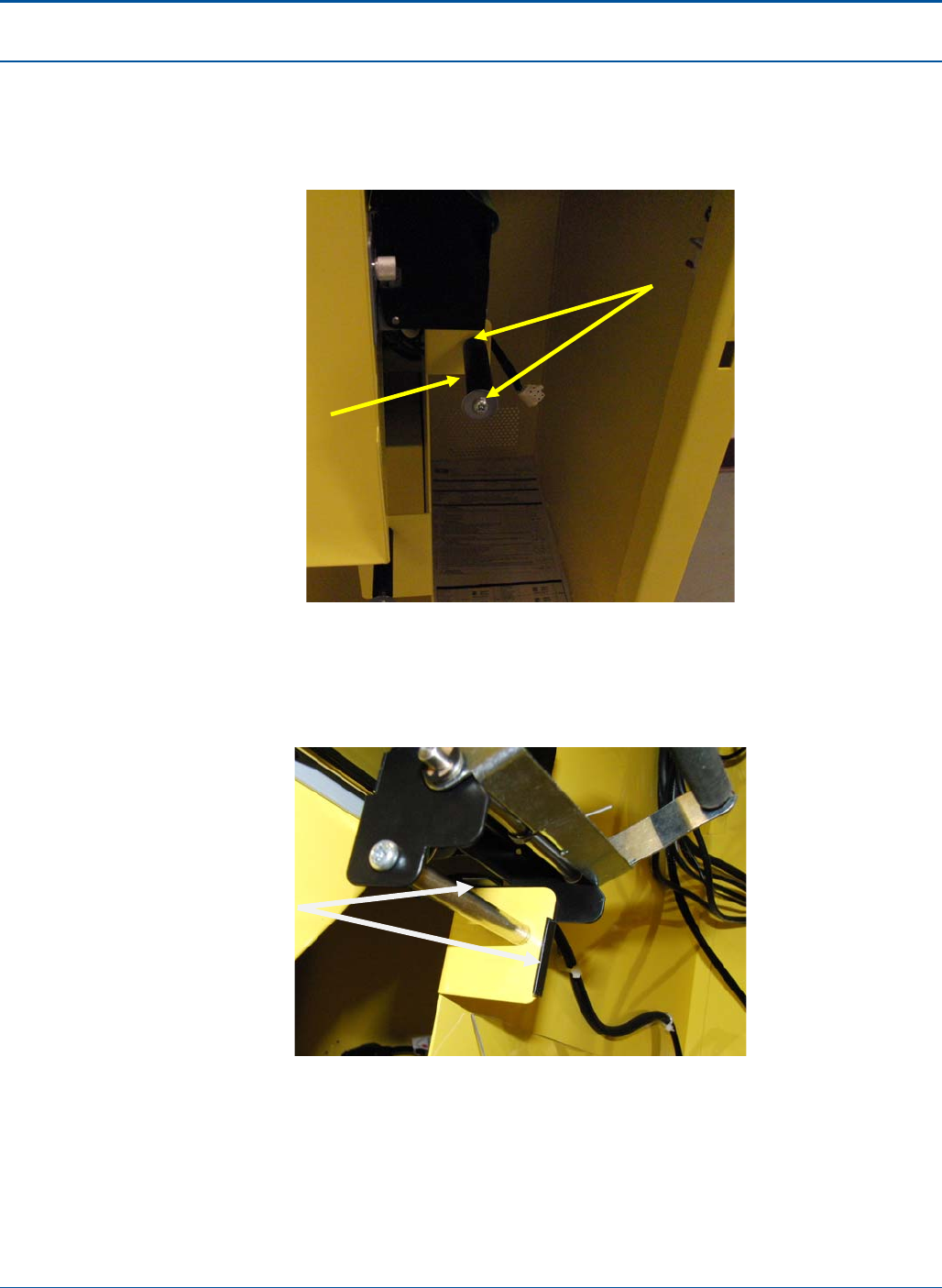
Component Procedures PAT Technical Manual
6-40 Confidential & Proprietary
9. Remove two SC76-0002 screws that are on the shaft, SH10-0039, closest to the
printer. It may be necessary to hold the shaft with pliers to prevent it from rotating
when removing screws. Remove the black plastic roller, SP60-3628, and washer,
return to spares stock.
Figure 80: Assembly Black Plastic Roller and Screws
10. Place the bracket assembly from step 7 behind the cabinet flange. Replace shaft,
SH10-0039, with the two screws, SC76-0002, making sure to run the screws
through the swing arm bracket assembly.
Figure 81: Assembly Swing Arm
SP60-03628
SC76-0002
Note how flanges
for swing arm
bracket secure to
cabinet flange.
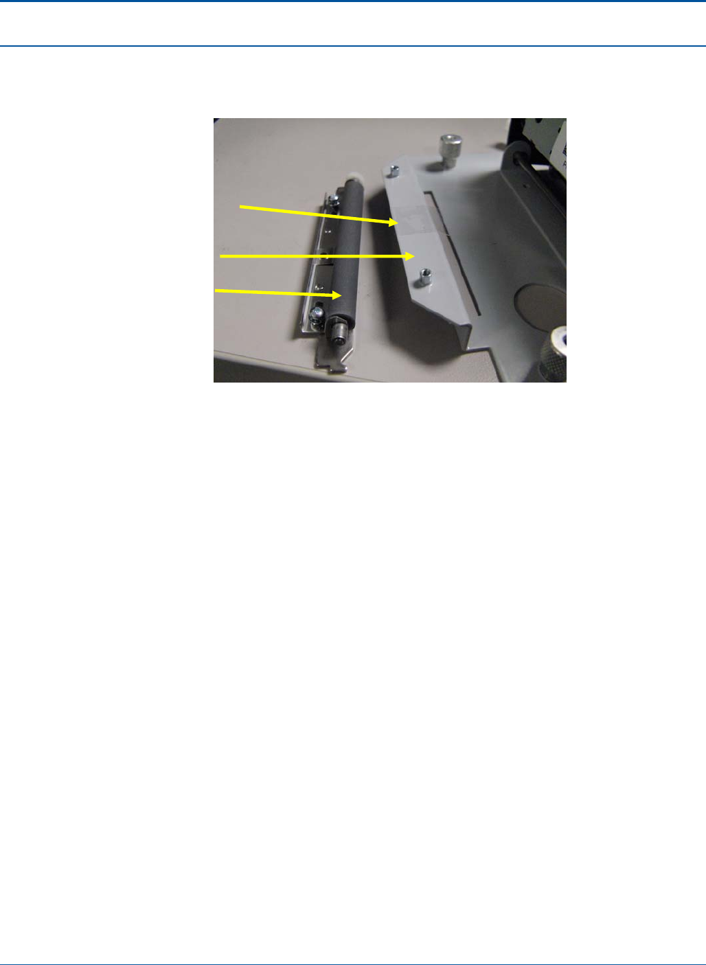
PAT Technical Manual Component Procedures
Confidential & Proprietary 6-41
11. Power down the terminal and remove printer assembly by loosening the two
thumbscrews and all cable assemblies. Remove printer roller from bracket, BR30-
0300.
Figure 82: Printer Roller Bracket
12. Bend mylar, GU30-0037, with tool, TL90-0363. Attach GU30-0037 to BR30-0300,
aligning the bend of GU30-0037 with the bend of BR30-0300.
13. Reattach the printer roller.
14. Reattach the printer assembly, secure the two thumbscrews and secure all cables.
GU30-0037
BR30-0300
Printer Roller

Component Procedures PAT Technical Manual
6-42 Confidential & Proprietary
6.6 Instant Ticket Assembly
The sections below provide the following procedures for these PCT components:
• Loading Instant Tickets
• Clearing an Instant Ticket Jam
• Replacing the Burster
6.6.1 Loading Instant Tickets
Up to three ticket packs may be loaded into a Burster at one time. To load a ticket pack,
the retailer must perform the following steps:
NOTE: Before loading instant ticket packs, make sure the packs have been activated.
1. Open the PAT:
a. Insert the red key into the lower keyhole on the side panel and turn the key.
b. Lift the PCT door handle on the side panel.
c. Open the PCT door.
2. Insert the blue key into the top barrel lock and turn the key.
3. Touch [Burster Status].
4. Touch [Load Pack] for the empty dispenser. The Enter Pack Number pop-up
screen displays.
5. Either scan the Pack Activity Card or manually enter the Game/Pack number. The
Game/Pack number is displayed.
NOTE: The instant ticket validation barcode can also be scanned.
6. Verify the Game/Pack number that is displayed matched the Pack Activity Card. If
they match, touch [OK].
7. Touch [YES] to load a full pack or [NO] to load a partial pack. If loading a full pack,
go to step 10.
8. Enter the starting ticket and touch [OK].
9. Enter the ending ticket and touch [OK].
10. Open the drawer and insert the lowest ticket number into the slot in the front of the
dispenser.
11. If the pack is loaded correctly, a “Successfully Loaded” pop-up message displays.
12. Touch [OK] and close the drawer.
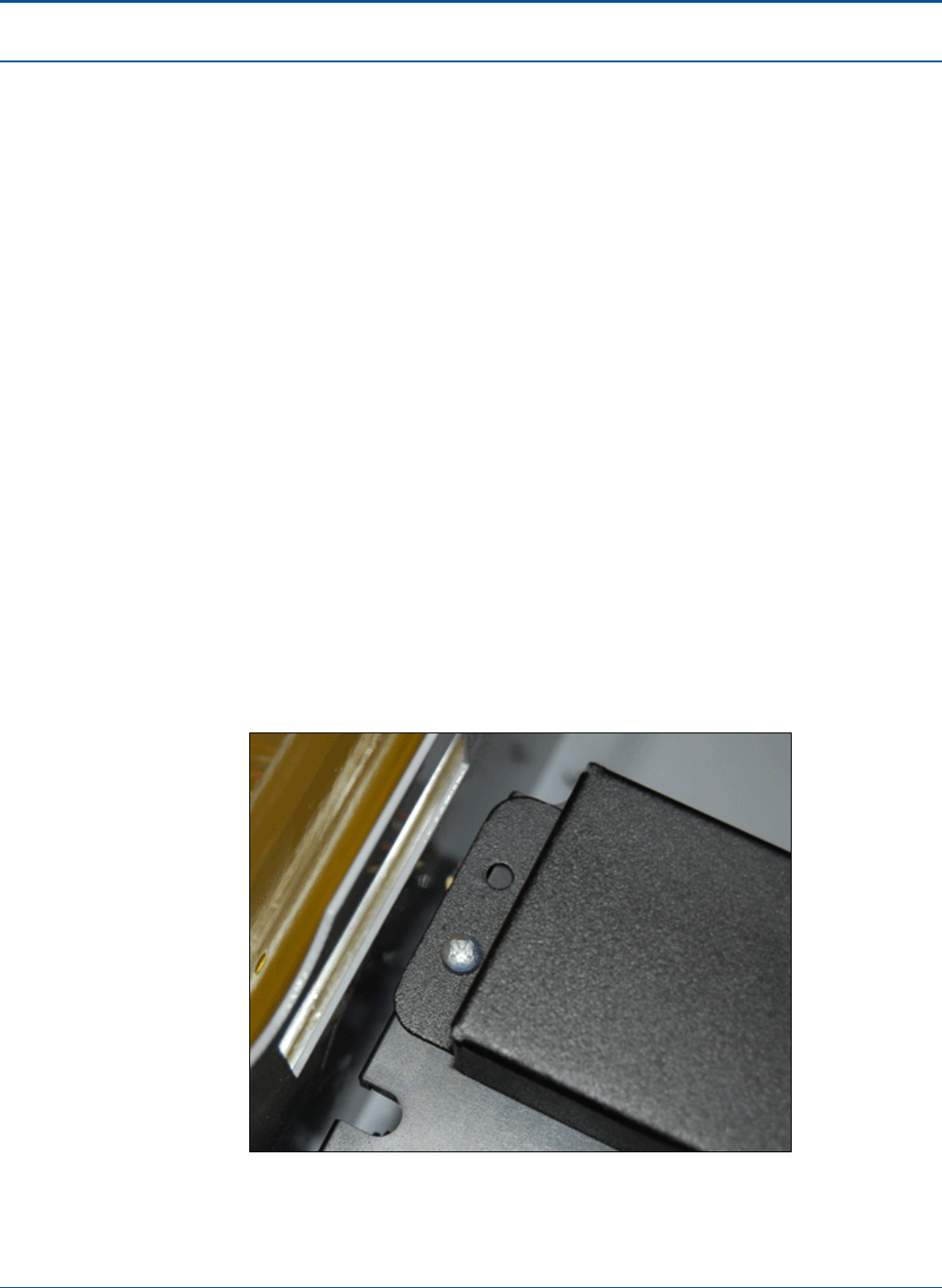
PAT Technical Manual Component Procedures
Confidential & Proprietary 6-43
13. Close and secure the PCT by performing the following steps:
a. Lift the PCT door handle on the side panel.
b. Shut the PCT door.
c. Lock the PCT door and remove the red key.
NOTE: The key can be removed only in the locked position.
6.6.2 Replacing the Burster
To replace a burster, perform the following:
1. Shut down the terminal.
2. Wait for the terminal relay to shutdown.
NOTE: You will hear five clicks as the terminal relay shuts down.
3. After the terminal relay shuts down, disconnect all power from the terminal.
4. Open the PAT:
a. Insert the red key into the lower keyhole on the side panel and turn the key.
b. Lift the PCT door handle on the side panel.
c. Open the PCT door.
5. Open an instant ticket drawer.
6. Remove the one (1) screw on the burster wire protective cover assembly.
Figure 83: Burster Wire Protective Cover screw
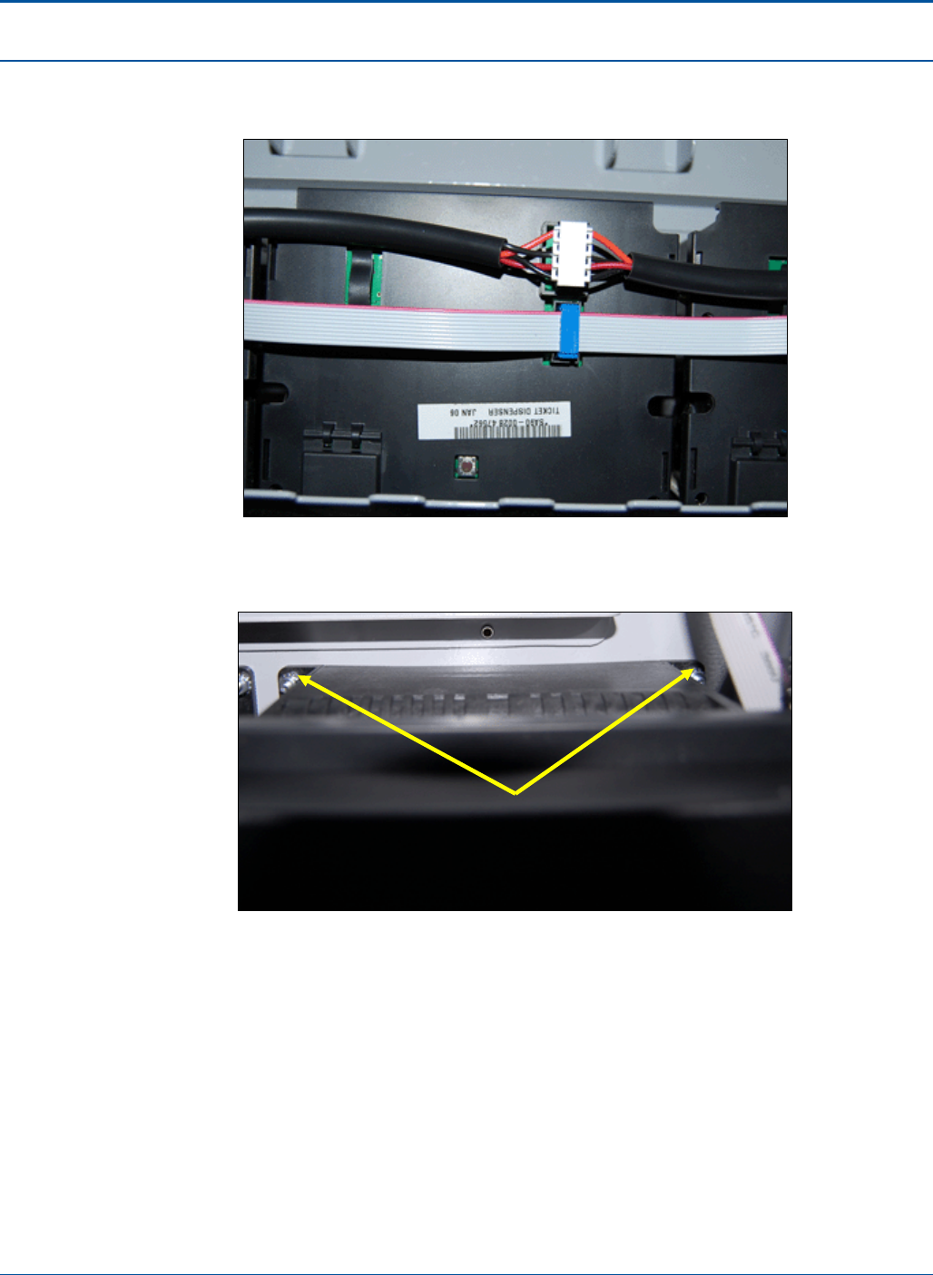
Component Procedures PAT Technical Manual
6-44 Confidential & Proprietary
7. After the burster wire protective cover assembly has been removed, detach the
wires connected to the burster to be removed.
Figure 84: Burster Assembly Wires
8. Remove the two (2) burster assembly hex nuts at the base of the burster.
Figure 85: Burster Assembly Hex Nuts
9. To replace the burster, perform the steps above in reverse.
Burster Assembly Hex Nuts
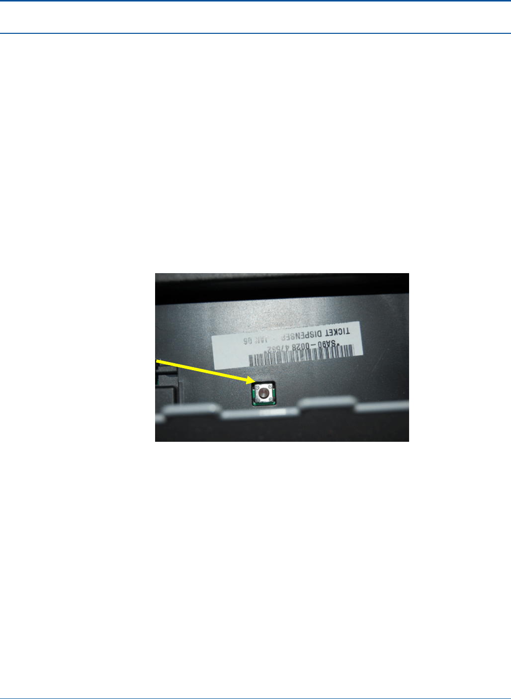
PAT Technical Manual Component Procedures
Confidential & Proprietary 6-45
6.6.3 Clearing an Instant Ticket Jam
To clear a ticket jam in a Burster, perform the following:
1. Open the PAT:
a. Insert the red key into the lower keyhole on the side panel and turn the key.
b. Lift the PCT door handle on the side panel.
c. Open the PCT door.
2. Insert the blue key into the top barrel lock and turn the key.
3. Touch [Burster Status].
4. Pull out the Burster rack that has the jammed Burster.
5. Press the Reverse button located on the front top center of the Burster. The
jammed ticket will reverse out of the Burster.
Figure 86: Reverse Button on Burster
6. If the jammed ticket is damaged, remove it from the pack.
7. On the Ticket Burster screen, confirm that the Burster indicates an Empty status.
8. Reload the pack into the Burster.
9. Close and secure the PCT by performing the following steps:
a. Lift the PCT door handle on the side panel.
b. Shut the PCT door.
c. Lock the PCT door and remove the red key.
NOTE: The key can be removed only in the locked position.
NOTE: The PCT does not reconcile inventory of damaged or otherwise unsellable
tickets that are removed from a pack.
Reverse
button

Component Procedures PAT Technical Manual
6-46 Confidential & Proprietary
6.7 Printer Assembly
The PCT terminal houses a printer that automatically prints a variety of sales reports. It is
integrated with the main housing and is equipped with a friction-type paper feed. The
printer uses 3.25-inch-wide paper stock and prints at a speed of about six inches per
second with a resolution of 200 dots per inch. The printer assembly includes a cutter
assembly that automatically cuts each report.
6.7.1 Replacing the Printer
To replace the printer, perform the following:
1. Shut down the terminal.
2. Wait for the terminal relay to shutdown.
NOTE: You will hear five clicks as the terminal relay shuts down.
3. After the terminal relay shuts down, disconnect all power from the terminal.
4. Open the PAT:
a. Insert the red key into the lower keyhole on the side panel and turn the key.
b. Lift the PCT door handle on the side panel.
c. Open the PCT door.
5. Release the print head by pressing the side latch located on top- right side of the
print head.
Figure 87: Print Head Release Latch
6. Remove the paper.
7. Close the print head.
Print Head Release Latch
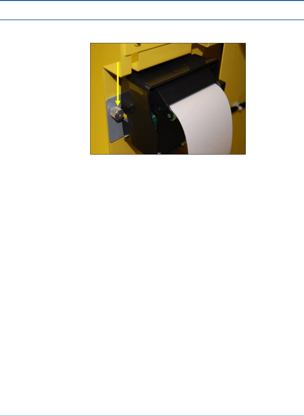
PAT Technical Manual Component Procedures
Confidential & Proprietary 6-47
8. Turn the two (2) thumbscrews counter clockwise to detach the printer from the
terminal.
Figure 88: Printer Thumbscrew
9. Remove the printer cable from the back of the printer.
NOTE: The cable connector that is removed has a locking clamp that will require
pinching the locking tab to release. Pull the connector towards the rear of the
printer.
10. Replace the printer.
11. Reconnect the printer cable.
NOTE: Make sure that you have aligned the connector properly and then slowly
insert until the clamp locks in place.
12. Properly dress the cable using one of the guide slots, and press the cable to
secure in place.
13. Return the printer to its correct position.
14. Reload the paper.
15. Power up the terminal.
Thumbscrew (1 of 2)
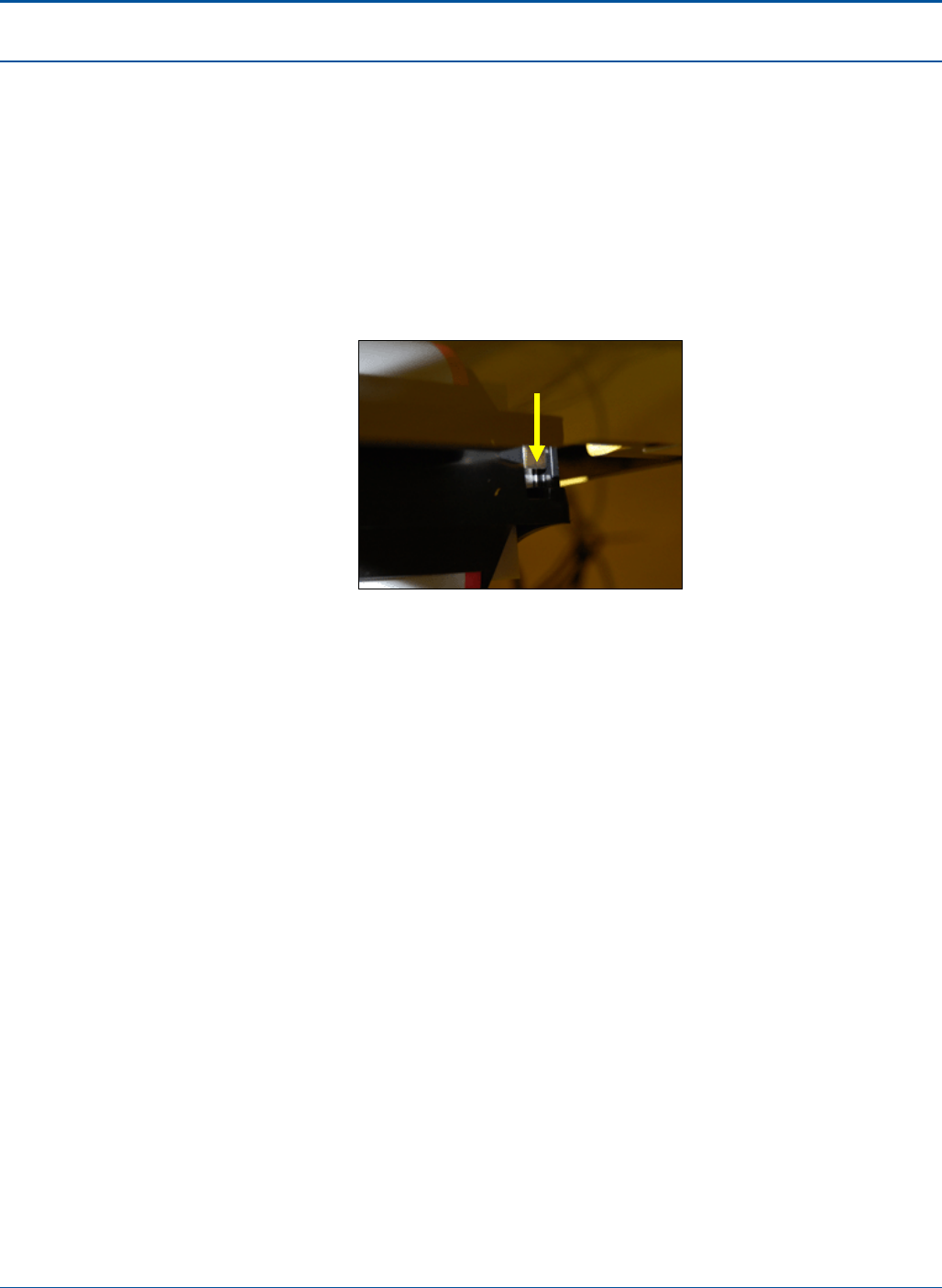
Component Procedures PAT Technical Manual
6-48 Confidential & Proprietary
6.7.2 Loading Printer Paper
To load paper into the PCT printer, the retailer must perform the following steps:
1. Open the PCT by performing the following steps:
a. Insert the red key into the lower keyhole on the side panel and turn the key.
b. Lift the PCT door handle on the side panel.
c. Open the PCT door.
Figure 89: Print Head Release Latch
2. Release the print head by pulling up on the latch located on top-right side of the
printer.
3. Remove any paper and push the print head firmly back into place, making sure
that the print head is locked into place. (The print head makes an audible click
when it is locked.)
4. Remove used roll from printer well. (Do not throw away paper spindle.)
5. Place paper spindle through new paper roll.
6. Place the new roll of paper and spindle onto the paper well brackets, feeding the
paper from the bottom of the roll.
7. Insert the leading edge of paper under the print head. Push the edge into the slot
and through the paper guide as far as it will go, about 1 inch. The printer will then
automatically feed the paper and will cut off any excess paper.
8. Slide the drawer closed by lifting up and firmly pushing the drawer forward into the
PAT.
9. Close and secure the PCT by performing the following steps:
a. Lift the PCT door handle on the side panel.
b. Shut the PCT door.
c. Lock the PCT door and remove the red key.
NOTE: The key can be removed only in the locked position.
Print Head Release Latch

PAT Technical Manual Component Procedures
Confidential & Proprietary 6-49
6.7.3 Clearing a Printer Jam
To clear a paper jam in the printer, the retailer must perform the following steps:
1. Open the PCT by performing the following steps:
a. Insert a key into the lower keyhole on the side panel and turn the key.
b. Lift the PCT door handle on the side panel.
c. Open the PCT door.
Figure 90: Print Head Release Latch
2. Release the print head by pressing the side latch located on right side of the print
head.
3. Remove any paper and push the print head firmly back into place, making sure
that the print head is locked into place. (The print head makes an audible click
when it is locked.)
4. Re-feed paper back into the printer.
5. Close and secure the PCT by performing the following steps:
a. Lift the PCT door handle on the side panel.
b. Shut the PCT door.
c. Lock the PCT door and remove the red key.
NOTE: The key can be removed only in the locked position.
Print Head Release Latch
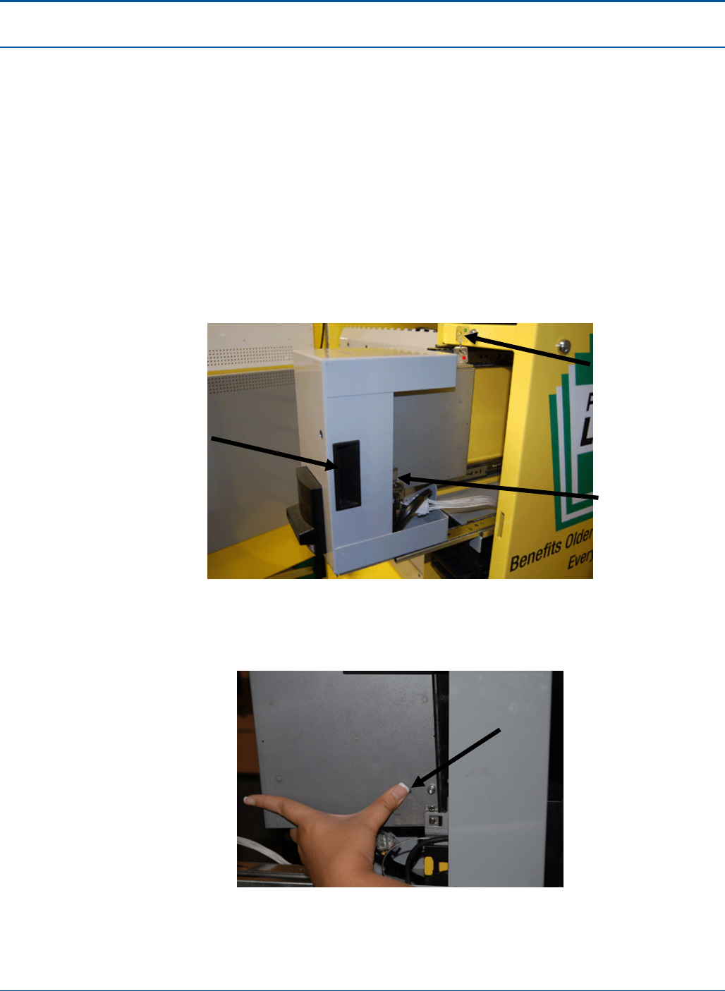
Component Procedures PAT Technical Manual
6-50 Confidential & Proprietary
6.8 Removing the Currency Cassette
To remove the currency cassette, the retailer must perform the following steps:
1. Open the PCT by performing the following steps:
a. Insert the red key into the lower keyhole on the side panel of PCT and turn
the key.
b. Lift the PCT door handle on the side panel.
c. Open the PCT door.
2. With the green key, unlock the Bill Enclosure Cabinet and pull out the currency
cassette tray.
Figure 91: Bill Enclosure Cabinet
3. Press the two tabs on each side of the bill stacker and lift it up from the Bill
Enclosure Cabinet.
Figure 92: Print Head Release Latch
Right Tab
Bill
Enclosure
Keyhole &
Green Key
Handle
Left Tab
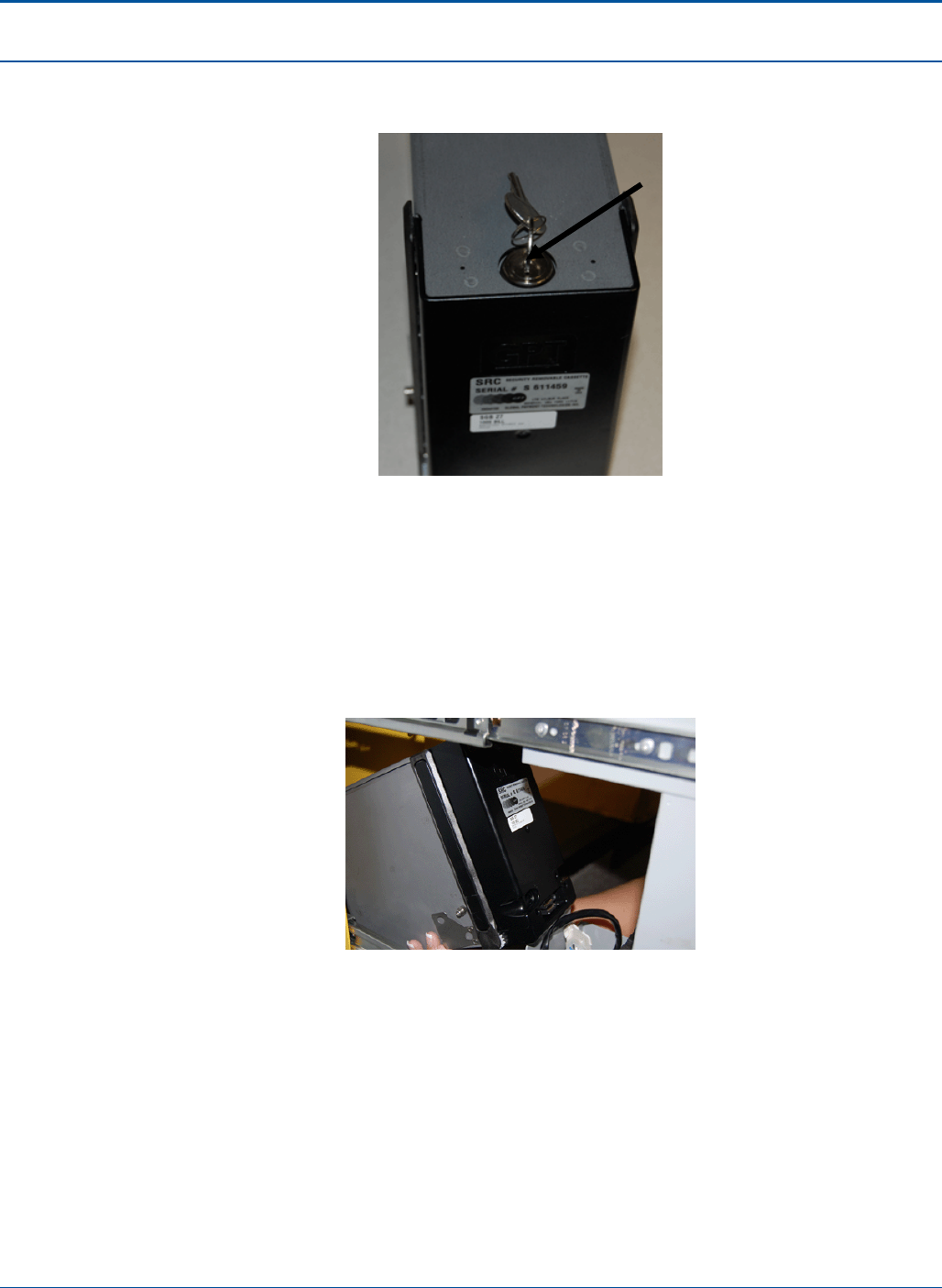
PAT Technical Manual Component Procedures
Confidential & Proprietary 6-51
4. Insert the Currency Cassette key in the keyhole on the top of the cassette and
unlock the cassette.
Figure 93: Currency Cassette Key
5. Remove the bills. Make sure that the bill plate springs back to the top of the
cassette.
6. Lock the cassette door.
7. Return the cassette to the Bill Enclosure Cabinet, placing the cassette with the
serial number label down, connecting the 14-pin connector, until the tabs click.
There will be a whirling sound confirming that the Bill Acceptor has reset itself.
Figure 94: Reinsert Currency Cassette
8. Raise the Bill Enclosure Cabinet closed and lock it.
NOTE: When the Currency Cassette is removed, the PCT will not accept bills.
9. Close and secure the PCT by performing the following steps:
a. Lift the PCT door handle on the side panel.
b. Shut the PCT door.
c. Lock the PCT door and remove the red key.
NOTE: The key can be removed only in the locked position.
Currency
Cassette Key
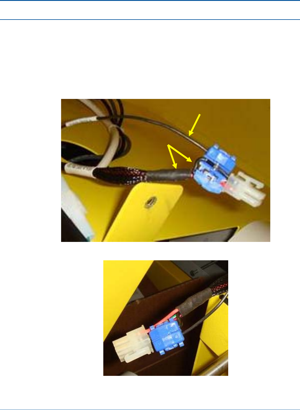
Component Procedures PAT Technical Manual
6-52 Confidential & Proprietary
6.9 Printer Ground Rework Process
1. Pull down or remove the jacket (heat shrink) of the existing printer cable CA05-
0518-01_A.
2. Open the blue clamp on cable CA05-0614 and rout the thicker black ground wire,
closest to the orange wire, through clamp.
3. Close the clamp tightly with pliers.
Figure 95: Routing the Exposed Printer Cable through the Blue Cable Clamp
Figure 96: The Closed Clamp on Cable
CA05-0614
Black wire
CA05-0518-01_A
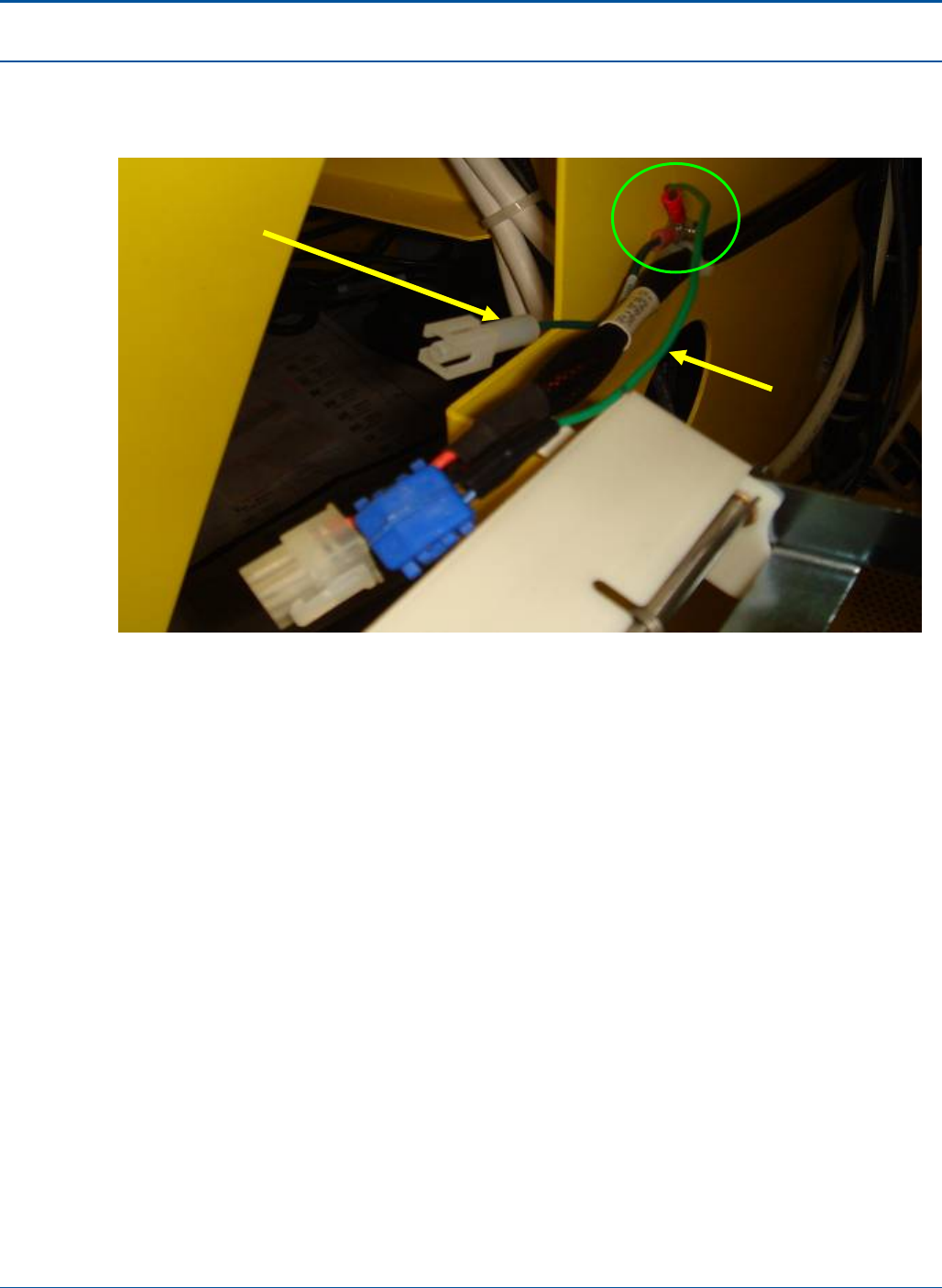
PAT Technical Manual Component Procedures
Confidential & Proprietary 6-53
4. Secure the ring terminals of CA05-0614 and CA05-0613 to ground stud located on
terminals cabinet wall as shown in photograph below (Tightening torque 6-7
kgfcm).
Figure 97: Connecting Printer Grounds to the Terminal’s Cabinet Wall
CA05-0613
CA05-0614
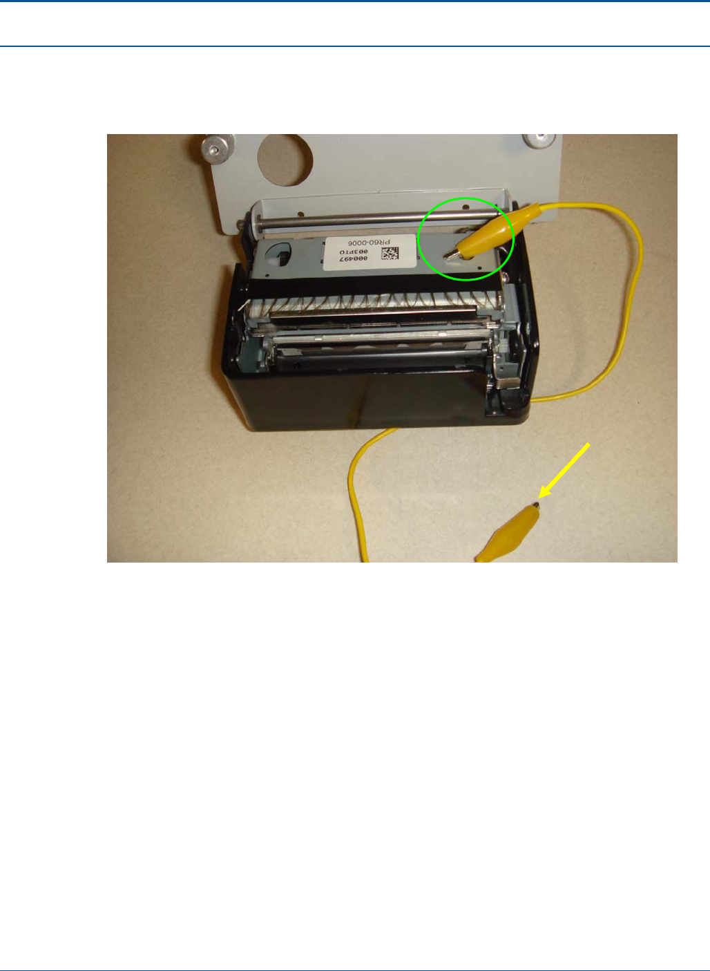
Component Procedures PAT Technical Manual
6-54 Confidential & Proprietary
5. Attach cable CA05-0610 to the printer’s chassis:
• Ensure Printer mechanism is properly grounded during rework by clamping
metal printer chassis and connecting to earth ground as shown.
Figure 98: Grounding the Printer Chassis During Rework
Attach to
earth ground
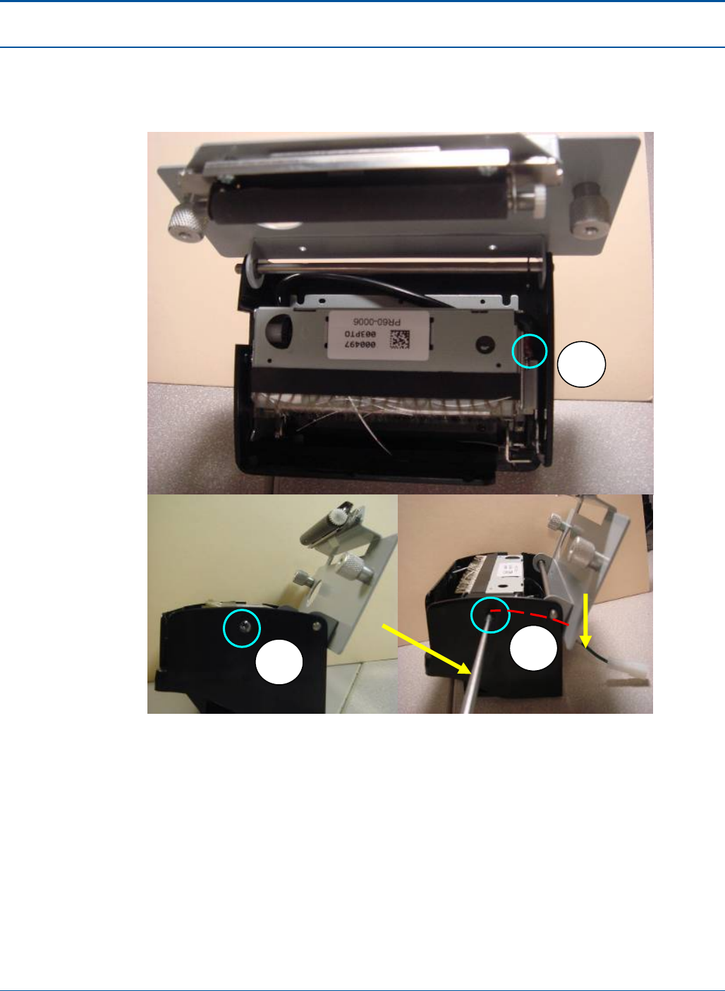
PAT Technical Manual Component Procedures
Confidential & Proprietary 6-55
• Locate the screw on side of the cutter chassis (See circle 1 below).
• Using cut out template, drill a .25” hole through the printer’s plastic sidewall
allowing a screw driver to access the screw (See circle 2 below).
Figure 99: Accessing Printer Screw
• Remove screw at location of circle 2.
• Align ring terminal of CA05-0610 to printer chassis.
• Route CA05-0610 as indicated by the dashed red line in the photograph above
and tighten the screw securing CA05-0610 to the printer’s chassis. Tightening
torque 4-5 kgfcm. (See circle 3 in the above figure).
Screw Driver
2
1
3
CA05-0610
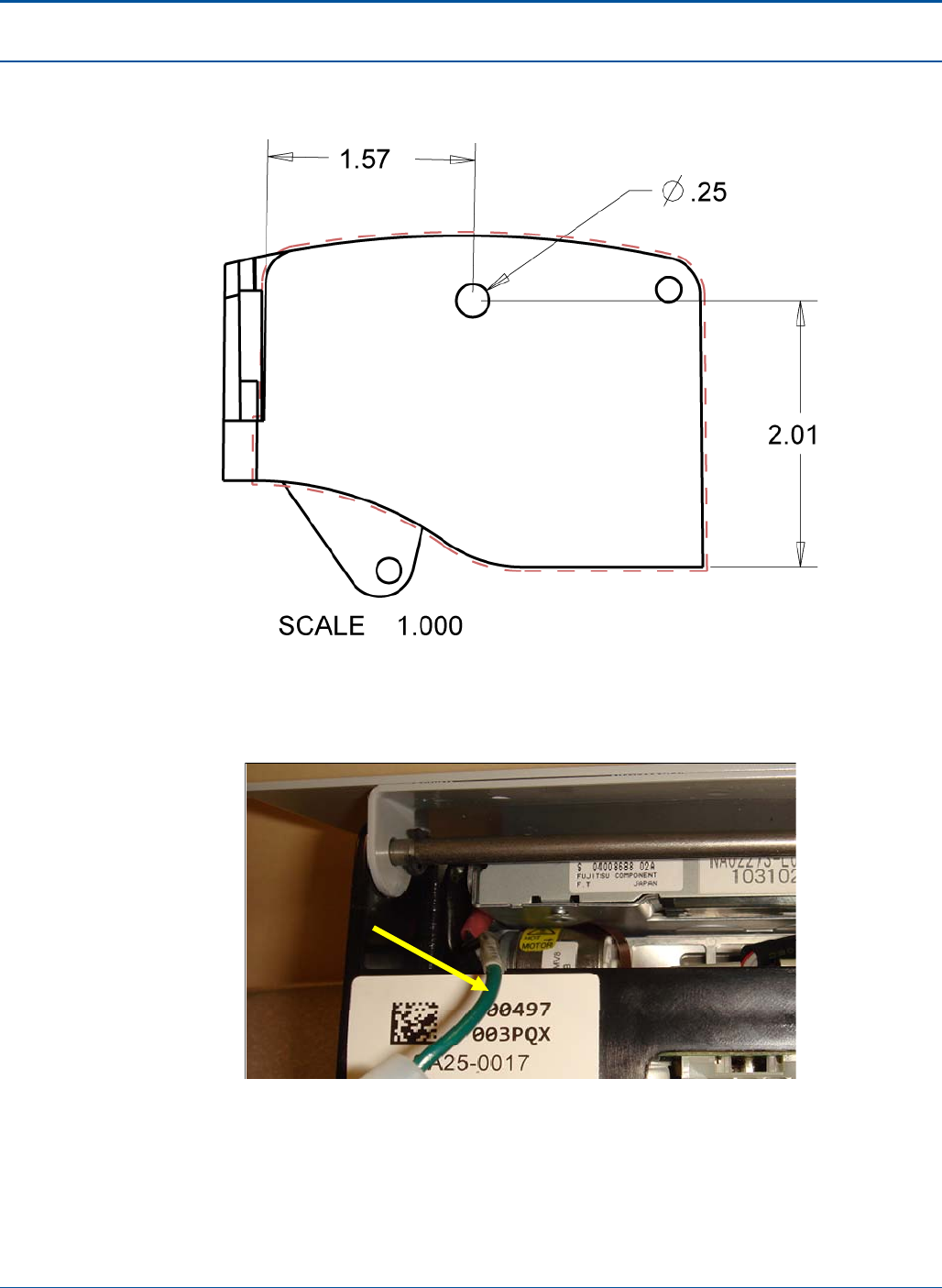
Component Procedures PAT Technical Manual
6-56 Confidential & Proprietary
6. The position of the hole to be drilled is shown in the full sized template presented
in the figure below.
Figure 100: Template for Position of the Hole Drilled in the Printer’s Sidewall
7. The routing of the ground cable as viewed from the bottom of the printer module is
shown in the figure below.
Figure 101: Printer Ground Wire, Viewed from the Bottom of the Printer
Ring terminal on
cable CA05-0610
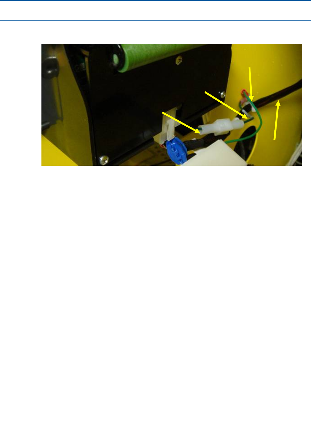
PAT Technical Manual Component Procedures
Confidential & Proprietary 6-57
8. When all connections have been completed the cables should appear as shown in
the photograph below.
Figure 102: Modified Printer Grounding Complete
CA05-0610
CA05-0613
CA05-0518_A
CA05-0614
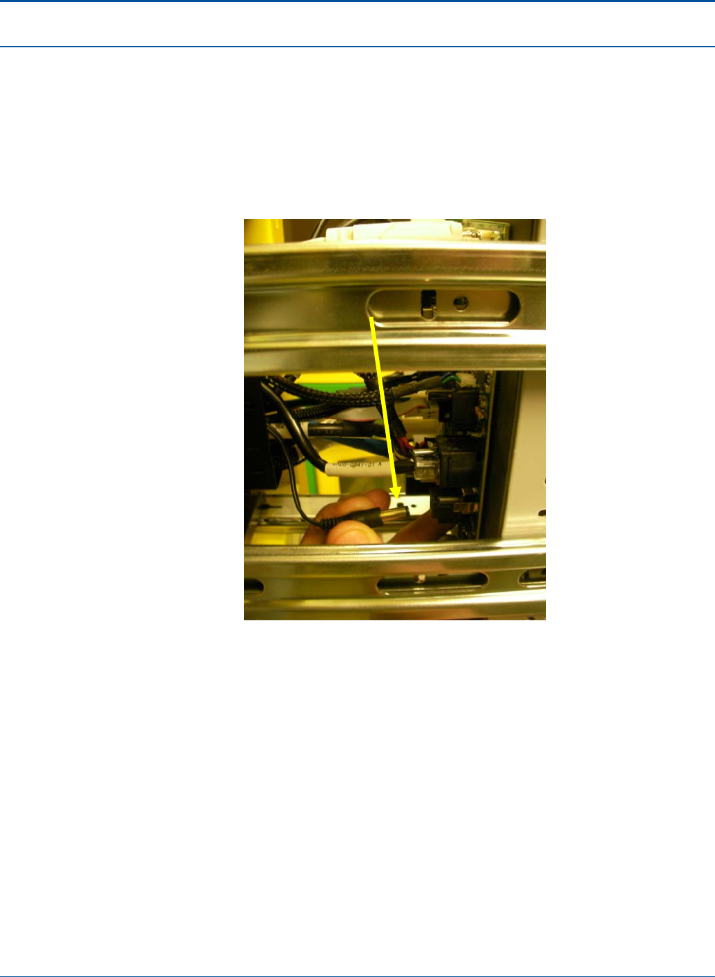
Component Procedures PAT Technical Manual
6-58 Confidential & Proprietary
6.10 Electronics Tray Rework Instructions
The following upgrades to the electronics tray will be performed in the Depot. Each PCT
will have its electronics tray swapped out in the field with a Depot modified tray. Ensure
the Field Technicians remove 12v power from PA20-0347 (security board) before
removing inner portion of electronic tray from PCT terminal and allow power supply to
click until drained of power.
Figure 103: Unplug 12V Power
Unplug 12v power supply
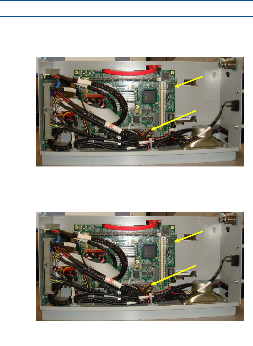
PAT Technical Manual Component Procedures
Confidential & Proprietary 6-59
6.10.1 Modified Connection of the Security Board’s USB Hub to the CPU
1. Replace the existing 60 pin cable, CA05-0445-02 with the revised cable, CA05-
0612.
Figure 104: Removing old 60 Pin Cable
2. Take note the connectors on the end of the cable are keyed to ensure proper
orientation with matting end. In addition, it is very important for the connector
containing the green heat shrink identifier, on one pin, to be connected to the
PA50-0026-01 (motherboard) as shown in the photograph below.
Figure 105: Connecting the new 60 Pin Cable to the Motherboard
CA05-0445-02
PA50-0026-01
(Motherboard)
CA05-0445-02
PA50-0026-01
(Motherboard)
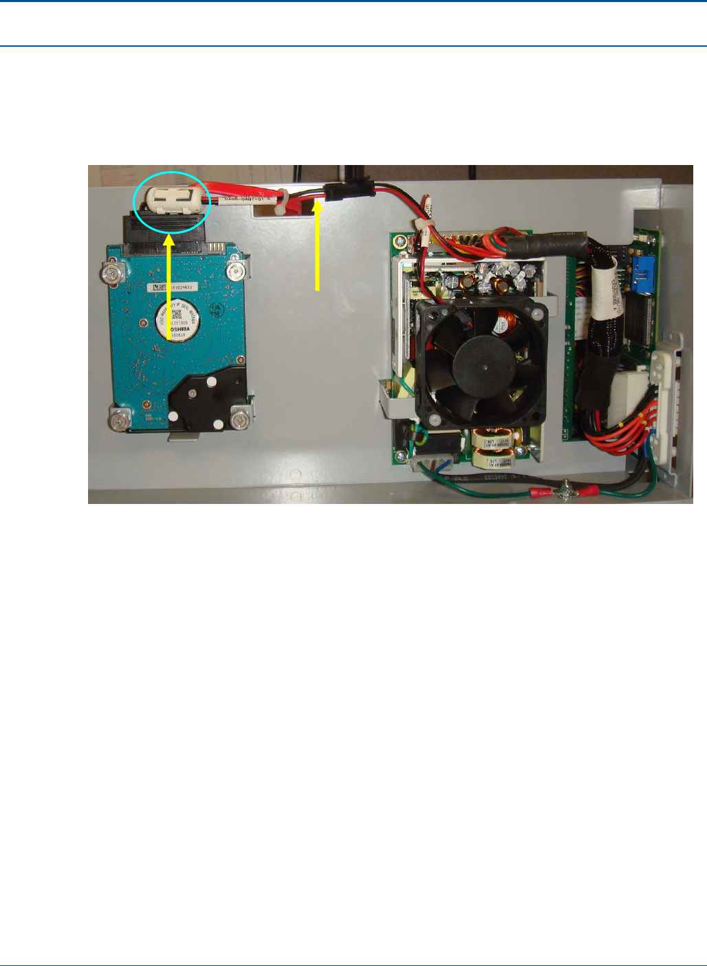
Component Procedures PAT Technical Manual
6-60 Confidential & Proprietary
6.10.2 Add Ferrite to the Hard Disk Drive 5 Volt Power Line
Attach the ferrite, ID65-0044, to the 5 volt power line for the hard disk drive as shown in
the photograph below.
Figure 106: Ferrite Attached to the Disk Drive’s 5 Volt Power Line
5V Power Cable
Ferrite ID65-0044
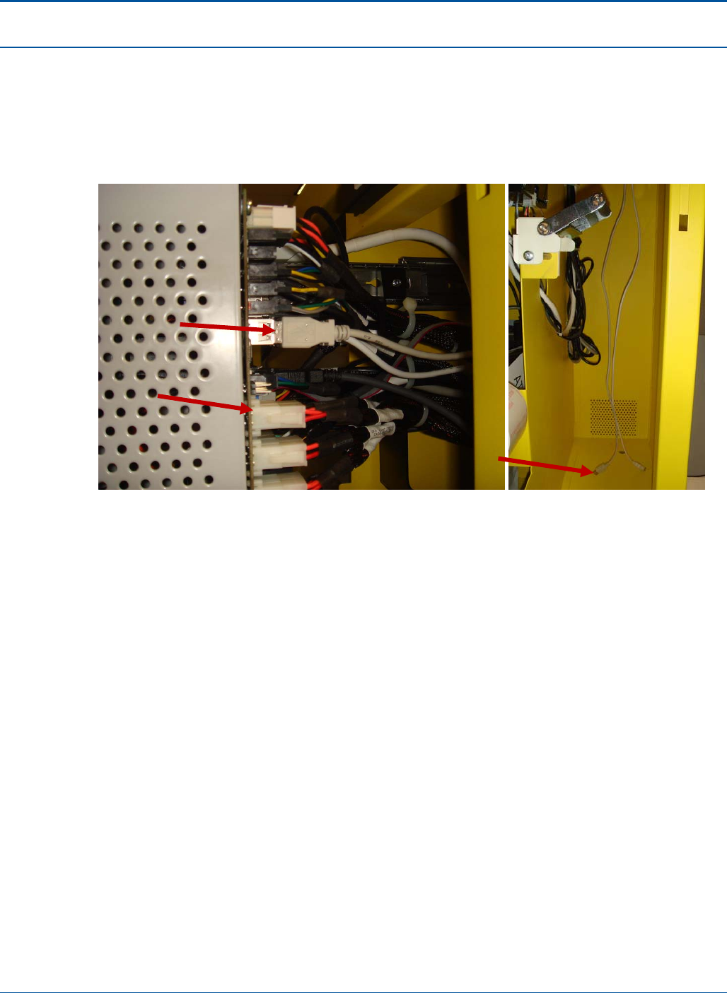
PAT Technical Manual Component Procedures
Confidential & Proprietary 6-61
6.10.3 Install 1pc USB extension onto Electronic tray
Plug CA90-0179 USB Extension cable to one of available USB ports located on PA20-
0347 security board and dress cable along cable harness in through the right side of
main cabinet.
Figure 107: Plug in the USB Connector
CA90-0179
PA20-0347
CA90-0179,
opposite end
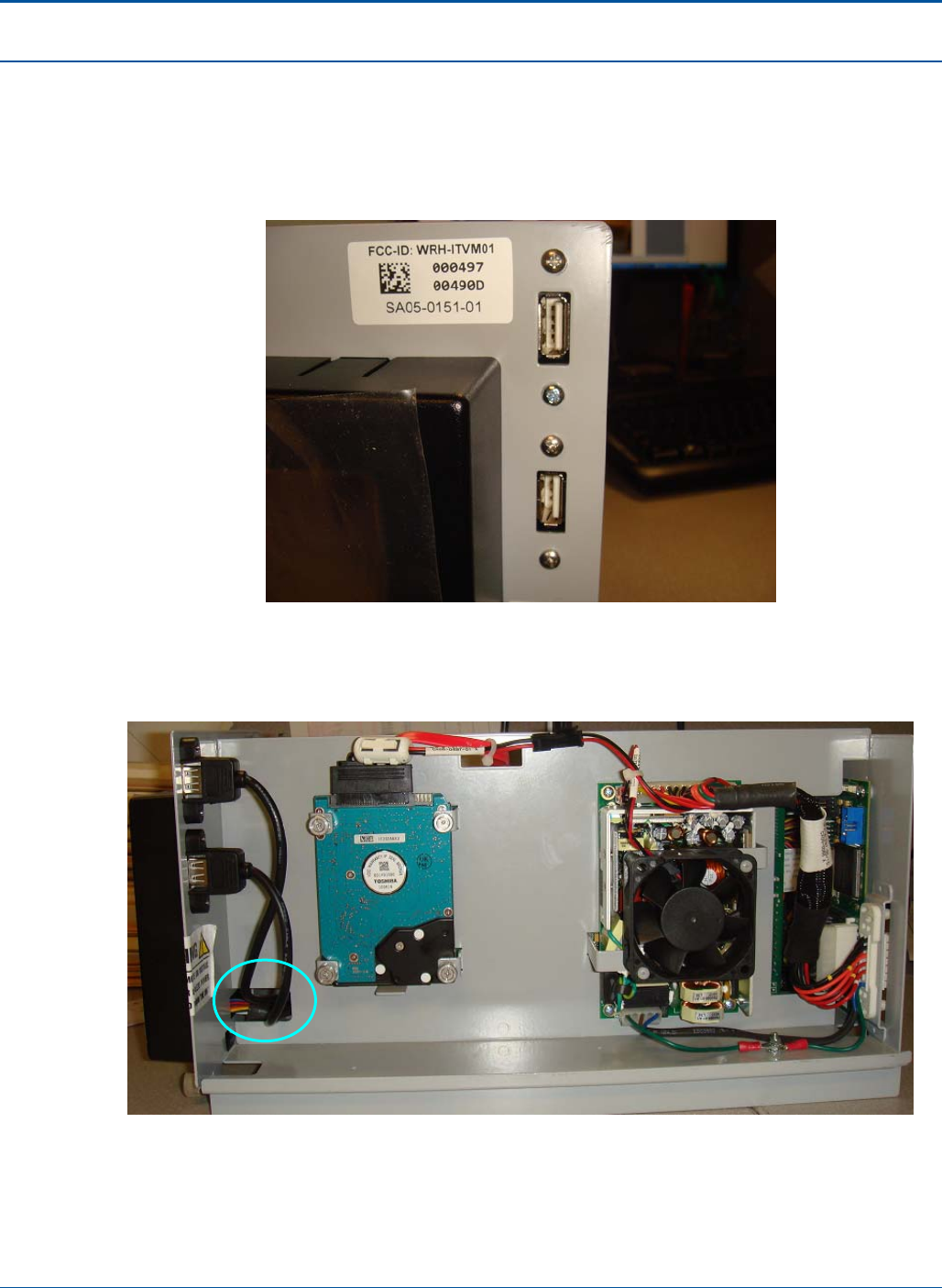
Component Procedures PAT Technical Manual
6-62 Confidential & Proprietary
6.10.4 Install 2pc USB extension onto Electronic tray
1. Secure CA10-0104 to front of electronic tray bracket, orientating the USB ports as
shown in figure below. Tightening torque is 4-5 kgfcm.
Figure 108: USB Connectors
2. When attaching CA10-0104, USB extension, route cables through the existing cut-
out of electronics tray; see circle 1a in the photograph below.
Figure 109: Attaching the New USB Extension Cable to the Electronics Tray
1a
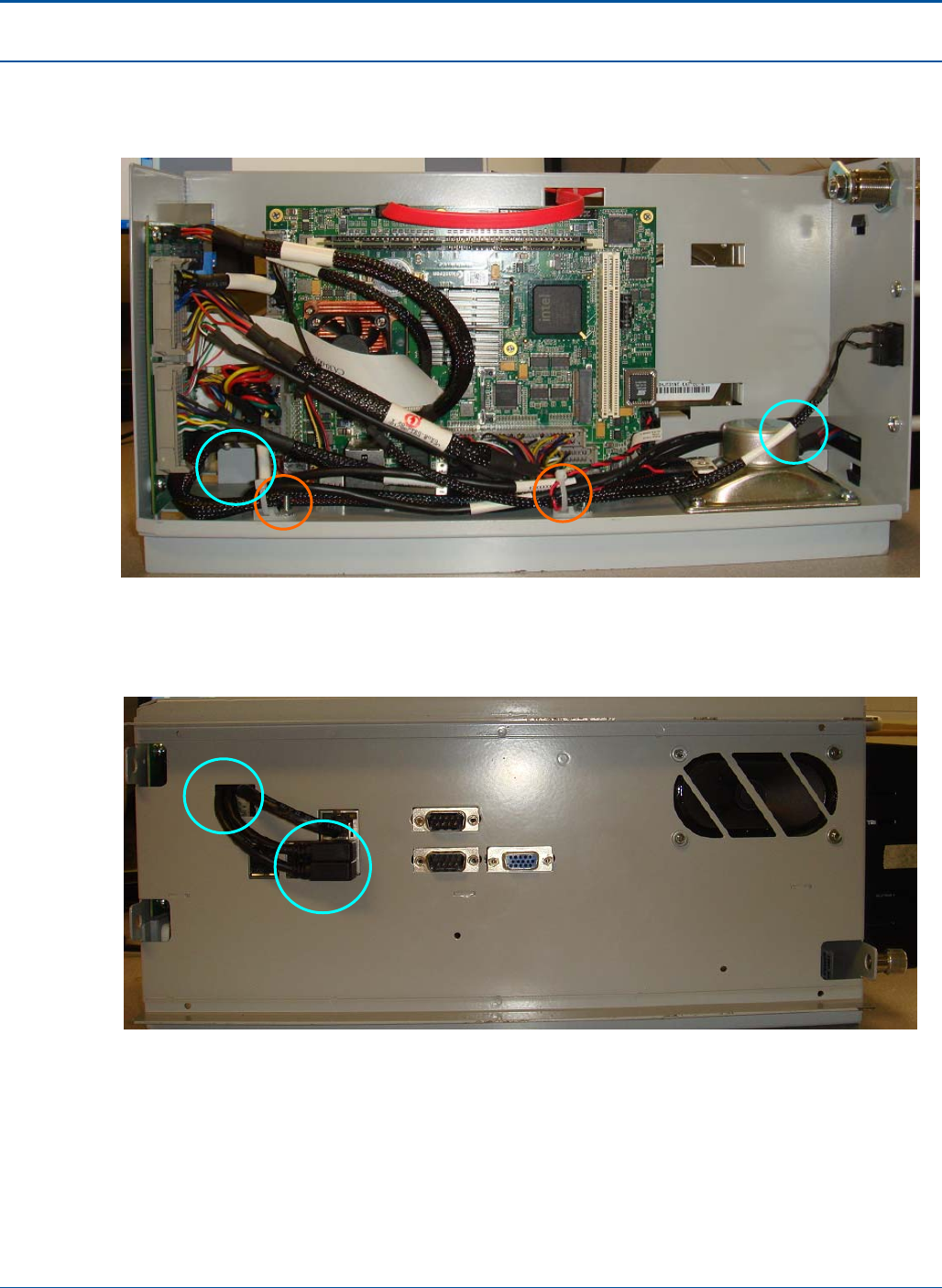
PAT Technical Manual Component Procedures
Confidential & Proprietary 6-63
3. Rotate the e-tray 180º horizontally so that the motherboard becomes visible, as
shown below. Continue routing the USB cables, from circle 1b to circle 2b, adding
TW60-0001 to locations T1 and T2.
Figure 110: Routing the USB Cable Pass the Motherboard
4. Flip the e-tray 90º vertically to expose the bottom. Plug in the USB connectors into
USB ports shown in circle 3c below.
Figure 111: Plug in the USB Connector
2b
T2 T1
1b
2c
3c
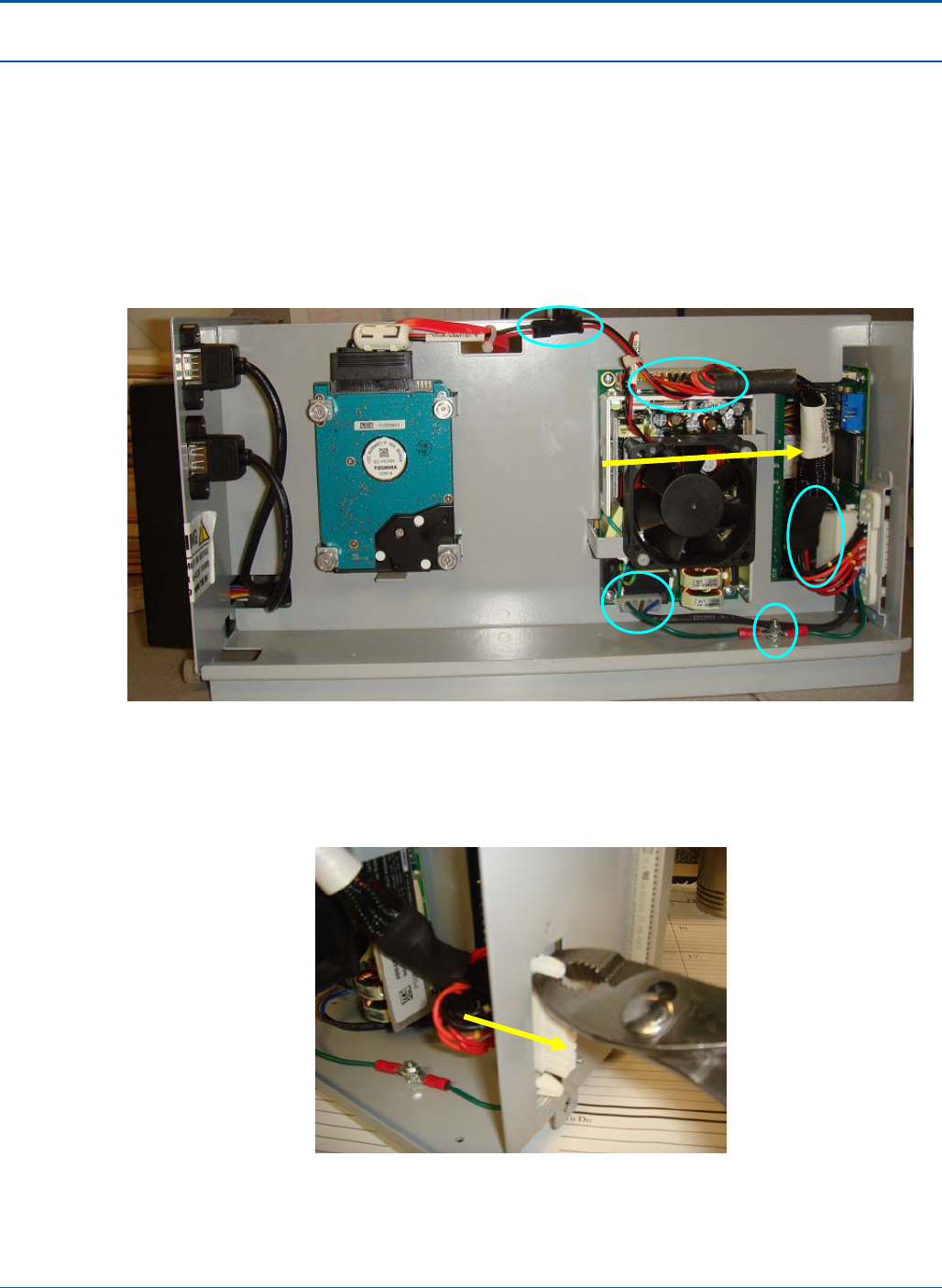
Component Procedures PAT Technical Manual
6-64 Confidential & Proprietary
6.10.5 Power Harness Rework Instruction
1. Replace the existing power harness, CA05-0441-01, with harness, CA05-0568_B.
• Unplug 4 locations (1-4), cutting tie wrap between 1&2 and remove two ground
wires (5) using 7/32 nut driver as shown in figure below. When removing the
two grounds, keep the 2 nuts (NU73-0001) and 1 star washer (WA73-0001) for
the installation of CA05-0568_B.
Figure 112: Power Harness Removal
• Next remove CA05-0568_A from electronics tray by applying pressure to the
AC/DC connector in below figure and pressing through electronic tray until
loose.
Figure 113: AC/DC connector removal
2
1
3
5
4
CA05-0568_A
AC/DC connector
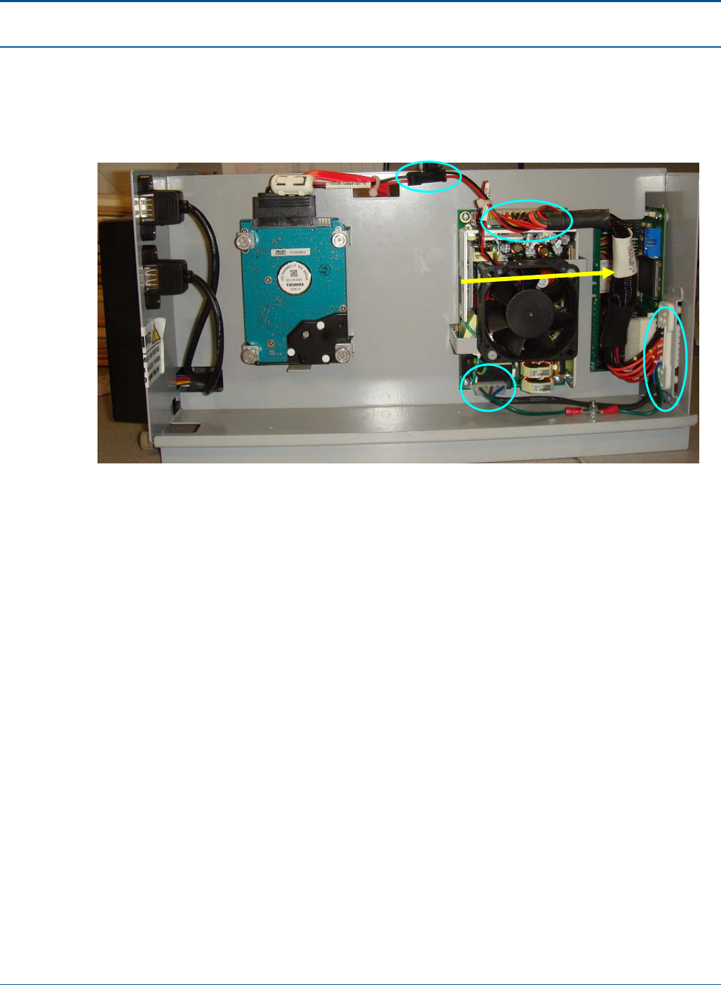
PAT Technical Manual Component Procedures
Confidential & Proprietary 6-65
6.10.6 Power Harness installation Instruction
1. Install CA05-0568_B into electronics tray by plugging in connectors labeled 1-4 in
figure below taking note to how each is keyed for proper insertion.
Figure 114: Power Harness Install (Inside)
2
1
3
4
CA05-0568_B
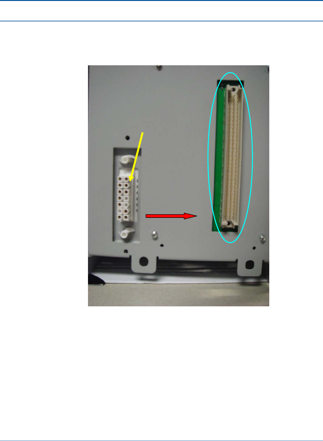
Component Procedures PAT Technical Manual
6-66 Confidential & Proprietary
2. When installing the AC/DC connector end through electronic tray ensure
connector is oriented correctly, as it is very difficult to remove the part and salvage
for reuse. Face the ribbed side of connector to the right of the electronic tray, or
towards the 98 pin connector, as highlighted in figure below.
Figure 115: Power Harness AC/DC Connector Install
AC/DC connector
Ribbed side
98 pin connector
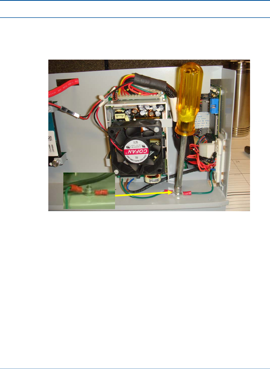
PAT Technical Manual Component Procedures
Confidential & Proprietary 6-67
3. Lastly, secure two ground wires by first placing the star washer (WA73-0001) onto
ground stud and then the ground wire leading from the AC/DC connector. Secure
with one nut (NU73-0001) and then place second ground wire leading from the
power supply connector (PS60-0019) onto ground stud and secure with second
nut (NU73-0001). Tightening torque 6-7 kgfcm.
Figure 116: Ground Cable Install
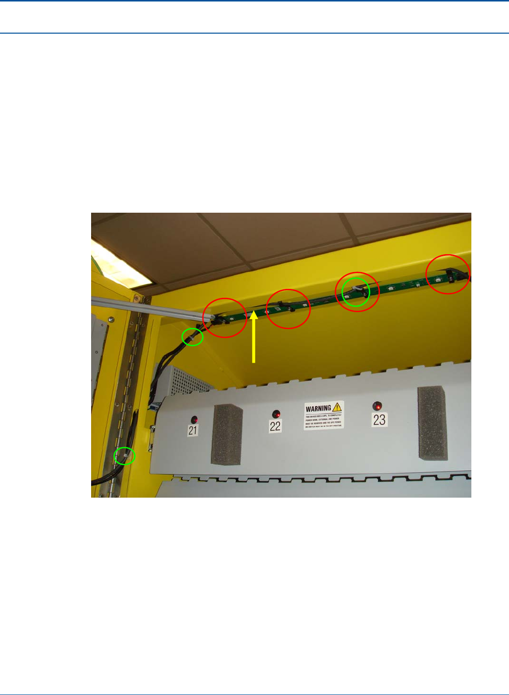
Component Procedures PAT Technical Manual
6-68 Confidential & Proprietary
6.10.7 Install USB Cable for USB/DVI Card
1. Cut the connectors off of each end of the existing 5 meter USB cable CA90-0160
which connects the security board to the USB/DVI card. If necessary, leave the
existing cable in place, as there is no need to remove it from its wiring bundle.
2. Carefully route the new cable CA90-0177.
3. Dress the cable CA90-0177 with TW60-0001 referenced by the 6 green circles.
The 4 red circles indicate the locations for BR20-0036 Bracket ITVM, USB Cable,
secured with existing SC74-0020, from PA20-0338 LED Bar, taking note that one
BR20-0036 has CA90-0177 tie-wrapped to it.
Figure 117: Cable Dressing
CA90-0177
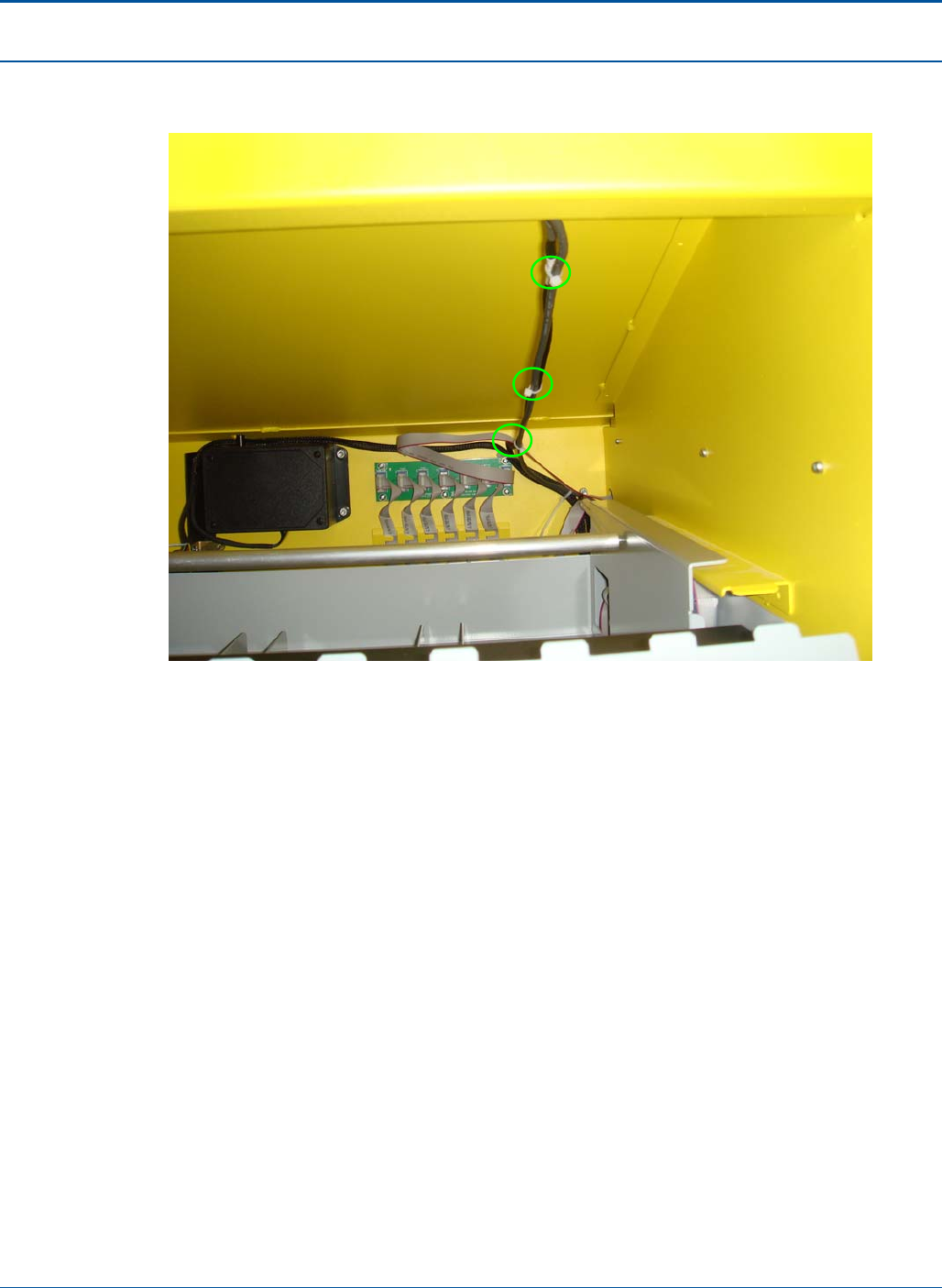
PAT Technical Manual Component Procedures
Confidential & Proprietary 6-69
4. Continue the cable dressing of CA90-0177 with TW60-0001, indicated by the 3
green circles, spacing roughly 6” apart.
Figure 118: Cable Dressing Continued
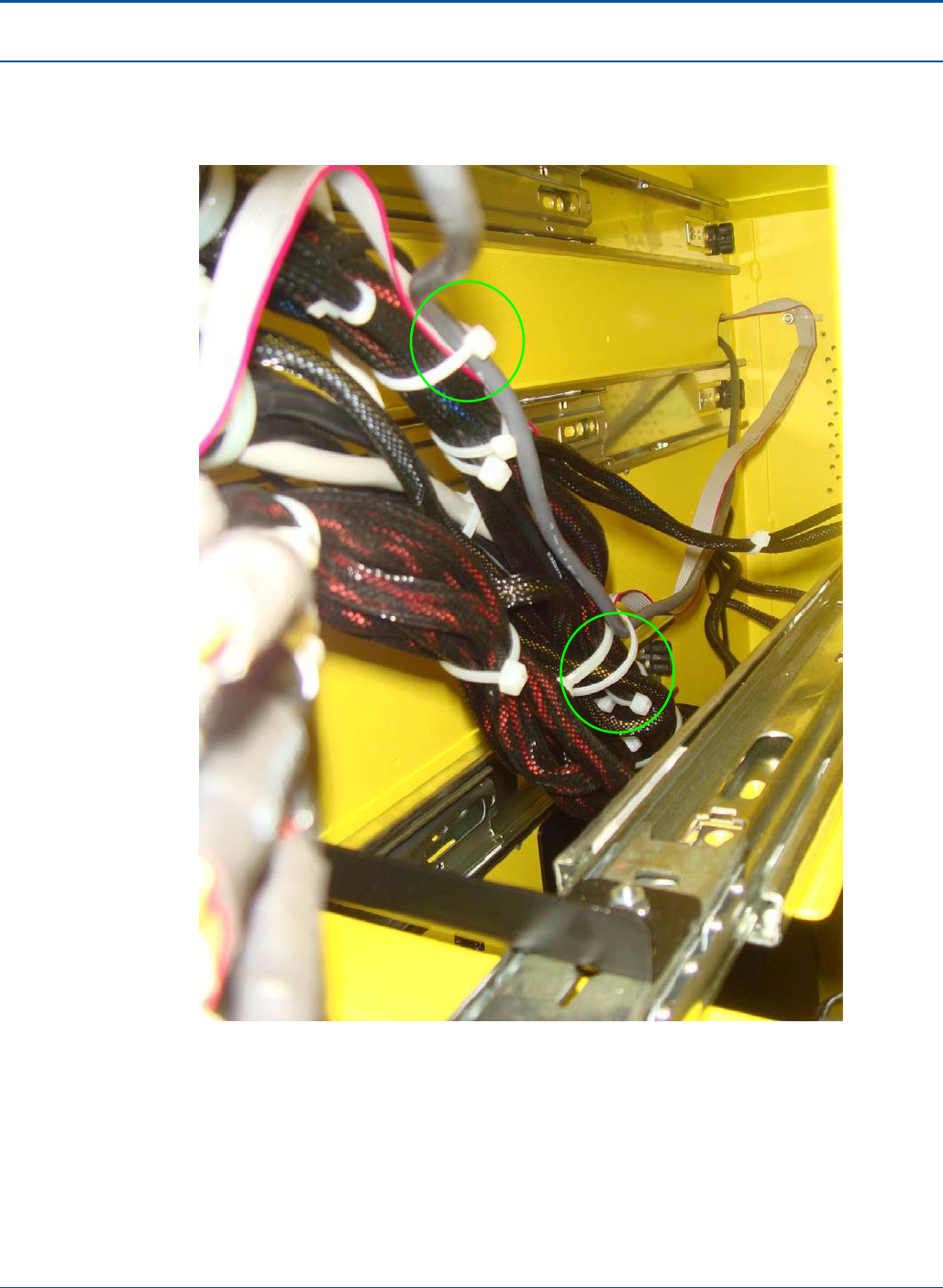
Component Procedures PAT Technical Manual
6-70 Confidential & Proprietary
5. Complete the dressing of CA90-0177 along the main harness, securing with 2pc
TW60-0025 as indicated by 2 green circles. Finally, connect CA9-0177 to the
PA20-0347 (Security board) into the previously used USB port of CA90-0160.
Figure 119: Cable Dressing Along Main Harness
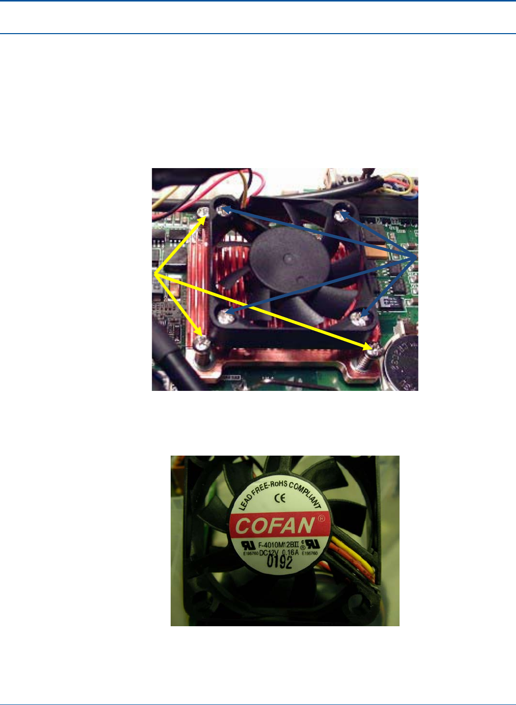
PAT Technical Manual Component Procedures
Confidential & Proprietary 6-71
6.11 CPU Fan Replacement
1. If the CPU fan has not been previously replaced in the field to the dual ball
bearing, its speed is below 2,700 RPM’s, or if it is vibrating and/or making
abnormal sounds the fan should be replaced. When replacing the fan do not
disturb the heat sink screws shown in the photograph below. Also, extreme
caution should be used when replacing the fan as to not disturb the heat sink, the
processor or compound between these two components.
Figure 120: Fan and Heat Sink
2. For reference, the dual ball bearing fan part number is shown in figure below as
being F-4010M12BII.
Figure 121: Dual Ball Bearing Fan
Heat Sink Screws Fan Screws
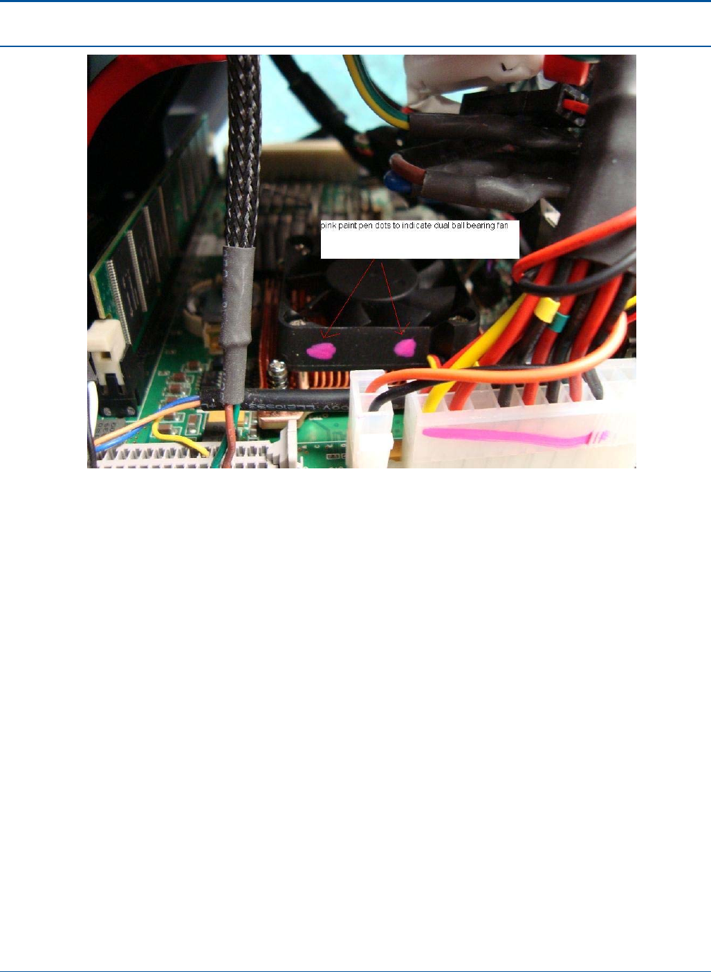
Component Procedures PAT Technical Manual
6-72 Confidential & Proprietary
Figure 122: Dual Ball Bearing Fan Indication

PAT Technical Manual Component Procedures
Confidential & Proprietary 6-73
6.12 Network Communications
6.12.1 Communications Installations in the Field
Prior to new installs, perform the following steps:
1. Contact the supervisor to obtain retailer information. If supervisor is not available,
contact Operations.
2. Verify that Operations has activated retailer.
NOTE: Refer to previous section, Setting up Terminal Communications, for
terminal configuration procedures.
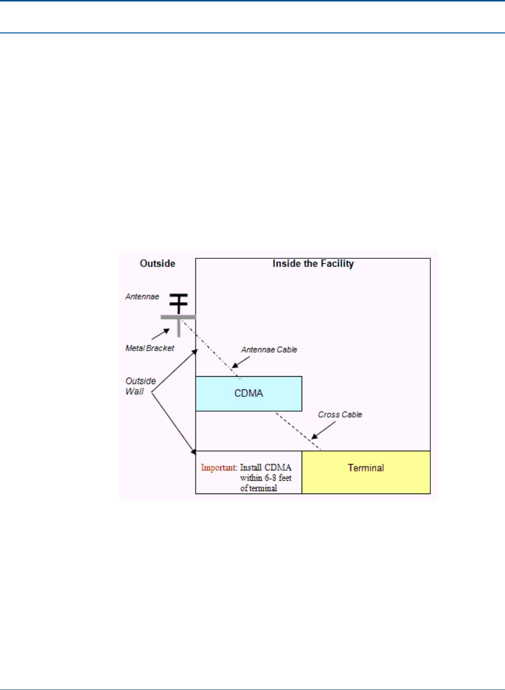
Component Procedures PAT Technical Manual
6-74 Confidential & Proprietary
6.13 Other Communications Setup Procedures
The WAVE™ may also communicate with the network via the following devices:
• CDMA - dynamic
• Wireless - static
6.13.1 CDMA Setup
The CDMA device does not require confirmation. This is performed at the Depot prior to
being issued to the install technician.
Important: The CDMA device must be located within 6-8 feet of the terminal. The
following diagram shows CDMA connections.
Figure 123: CDMA Communication Setup
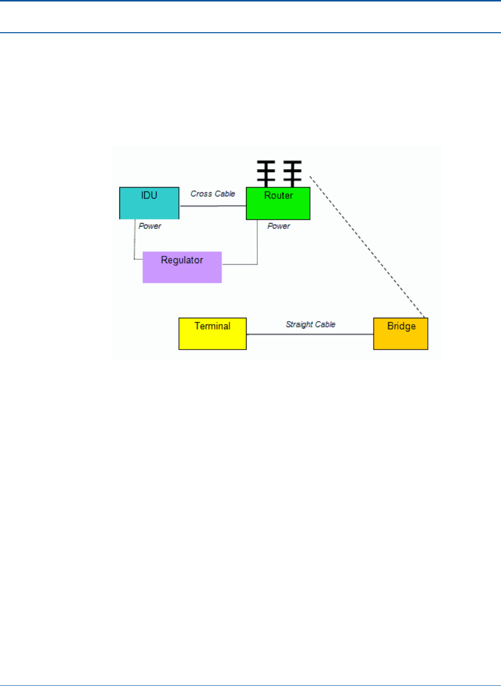
PAT Technical Manual Component Procedures
Confidential & Proprietary 6-75
6.13.2 Wireless Setup
Wireless communications will only be used in locations where inside wiring is not an
option.
In all cases, the Router is always placed with the IDU, and the Bridge is placed with the
terminal. The following diagram shows IDU, Router, and Bridge connections.
Figure 124: Wireless Communication Setup

7-1 Confidential & Proprietary
SECTION 7
TROUBLESHOOTING
7.1 Overview
This chapter:
• Describes common problems for the terminal and all peripherals
• Provides step-by-step troubleshooting procedures for the terminal and the
following peripherals/issues:
• Printer
• Document Scanner
• Handheld Scanner
• Touch Screen
• Flat Panel Display
• Hard Drive
• Other
Troubleshooting tips follow.
NOTE: When ANY terminal problem occurs, ALWAYS power off the terminal and wait 5
seconds to reboot. This frequently solves the problem.

Troubleshooting PAT Technical Manual
7-2 Confidential & Proprietary
7.2 Replaceable Parts Management
The following information pertains to replaceable or spare parts. In an effort to use spare
parts only when necessary, the following steps are recommended:
1. Each bench repair station will set up a testing area that includes storage space for
one of each working terminal part.
2. The functionality of each part will be verified and labeled as a "test part."
3. Before replacing any suspected malfunctioning part, first replace the part with the
test part; then test for functionality.
4. If the test part corrects the problem you are having with the terminal, you will know
that the part should be replaced.

PAT Technical Manual Troubleshooting
Confidential & Proprietary 7-3
7.3 Printing Problems
Printer Topic Troubleshooting Tips
Printer Jam 1. Attempt to remove jam or clear paper path.
2. Replace printer if problem persists.
Missing Print/No Print 1. Verify paper is properly loaded in printer.
2. Clean print head.
3. Recheck print quality by printing 10 test tickets.
4. Replace print head.
Paper Not Advancing 1. Verify paper is loaded correctly.
2. Verify printer door is properly closed.
3. Verify print head is securely locked.
4. Replace printer.
Partial or No Cut 1. Check the printer roller to make sure it rolls
freely.
2. Verify printer door is properly closed.
3. Replace printer if problem persists.

Troubleshooting PAT Technical Manual
7-4 Confidential & Proprietary
7.4 Printing Problems
Document Scanner Topic Troubleshooting Tips
Doc. Scanner - No Read 1. Cycle the scanner using the scanner utility eject
function in Diagnostics.
2. Inspect read head and make sure it is in the flat
position.
3. Make sure the doc scanner is clean.
4. Power off terminal and then power it on.
5. Calibrate the Document Scanner.
6. Replace Document Scanner assembly.
7. Replace terminal if problem persists.
Doc. Scanner - No Feed 1. Power off terminal and then power it on.
2. Cycle the scanner using the scanner utility eject
function in the Diagnostics.
3. Insert a completed play slip into the doc
scanner.
4. Replace Document Scanner assembly.
5. Replace terminal if problem persists.
Reading incorrectly 1. Verify scanner is clean.
2. Test scanner in Diagnostics.
3. Calibrate the Document Scanner.
4. Replace Document Scanner assembly.
5. Replace terminal if problem persists.
Doc Scanner - Noisy 1. Make sure that rollers are clean.
2. Replace Document Scanner assembly.
3. Replace terminal if problem persists.
Scanner motor stalls 1. Replace Document Scanner assembly.
2. Replace terminal if problem persists

PAT Technical Manual Troubleshooting
Confidential & Proprietary 7-5
7.5 Wireless Barcode Reader Problems
Wireless Barcode Reader
Topic Troubleshooting Tips
No light 1. Cycle power.
2. Replace ticket checker if problem persists.
No read 1. Verify power
2. Cycle power.
3. Verify cable is connected and not damaged.
4. Replace ticket checker if problem persists.
7.6 Charge Coupled Device (CCD) Reader Problems
CCD Topic Troubleshooting Tips
No response for CCD 1. Verify LED’s are lit.
2. Reconfigure the CCD Reader.
3. Replace the CCD Reader.
4. Replace the printer if problem persists.
5. Replace terminal if problem persists.
7.7 Touch Screen Problems
Touch Screen Topic Troubleshooting Tips
No touch 1. Power off terminal and then power it on.
2. Verify cables are properly connected.
3. Replace the display assembly.
4. Replace terminal if problem persists.
No or partial video 1. Cycle power.
2. Verify cables are properly connected.
3. Replace the display assembly.
4. Replace terminal if problem persists.
Scratch 1. Ignore if scratch is minor.
2. Replace the display assembly.

Troubleshooting PAT Technical Manual
7-6 Confidential & Proprietary
Touch Screen Topic Troubleshooting Tips
Calibration off 1. Recalibrate using Diagnostics function.
2. Make sure the bezel is not touching the touch
screen.
3. Replace the display assembly.
4. Replace terminal if problem persists.
Touch screen distorted 1. Reboot the terminal.
2. Verify cables are properly connected.
3. Replace the display assembly.
4. Replace terminal if problem persists.
7.8 Flat Panel Display Problems
Flat Panel Display Topic Troubleshooting Tips
No or partial video 1. Check power connection.
2. Verify data cable is connected and not
damaged.
3. Replace display.
4. Replace terminal if problem persists.
Scratch 1. Check/secure connections between the speaker
and Main Board.
2. If problem persists, replace the speaker.
Display shows distorted
images or multiple colors 1. Check cables to ensure they are properly
connected.
2. Replace display.
3. Replace terminal if problem persists.
Screen blank/does not work 1. Verify that terminal has power.
2. Verify data cables.
3. Replace terminal if problem persists.
Blue screen 1. Reboot the display.
2. Verify data cables.
3. Replace terminal if problem persists.

PAT Technical Manual Troubleshooting
Confidential & Proprietary 7-7
7.9 Other Problems
Other Topic Troubleshooting Tips
Invalid wager 1. Call Operations to verify no system problems.
2. Determine if operator error: Ask the retailer to
describe the function he/she was performing
when problem occurred.
3. Verify slips/ functions.
4. Replace terminal if problem persists.
Cannot sign on 1. Call Operations to verify no system problems
and to verify that retailer is still active in the
system.
2. Check network cable to make sure it is working.
3. Verify retailer information is correct.
4. Verify password.
5. Verify touch screen is properly calibrated.
6. Replace terminal.
No power 1. Check/secure power cord connection to terminal
and electrical outlet.
2. Verify that terminal has power; when initially
powered on the terminal emits one beep tone.
3. Verify functionality of electrical outlet.
4. Replace terminal.
Application error/memory
not read Replace terminal.

Troubleshooting PAT Technical Manual
7-8 Confidential & Proprietary
7.10 Trouble Codes
Trouble Code Code Description
0 State - Install Extrema
1 State - Extrema suspended
2 State - Meeting with State Rep.
3 State - Reinstall Extrema
4 State - Relocate Extrema
5 State - Remove Extrema
6 State - Retailer training
7 State – Site survey
8 State – Temp. removal
9 State Request – Sticker needed
10 Asset Verification needed
Communications Trouble Code
250 IW – Wire damaged
251 IW – No crossover cable
252 IW – Wires hanging
253 IW – Biscuit block not within 8” of TIM
254 IW – No biscuit block
255 IW – No inside wiring
256 IW – Bad inside wiring
700 Communications – Check last transaction
701 Communications – Error: Comm off line
703 Communications – No REC
704 Communications – No XMT
705 Communications – No XMT/No REC
706 Communications – Send error
707 Communications – Storm / Lightening damage
708 Communications – Vendor meet
710 Communications – Waiting for comms
711 Communications – Waiting for system to verify versions
799 Communications – Add text

PAT Technical Manual Troubleshooting
Confidential & Proprietary 7-9
VSAT/IDU Trouble Code
257 IDU – Not mounted
258 IDU – Not found
259 IDU – Broken pieces
260 IDU – Not working
261 IDU – Streaming
262 IDU – Configuration not correct
263 IDU – No power
264 IDU – No online light
265 IDU – No transmit
266 IDU – No receive
267 IDU – No outbound ID (SpaceNet)
268 IDU – LNB errors
269 IDU – Not configured on Radius Serv
270 IDU – Outbound errors
271 VSAT Dish – Broken pieces
272 VSAT Dish – Mount broken
273 VSAT Dish – Physically moved
274 VSAT Dish – Not aligned
275 VSAT Dish – Can’t get signal
276 VSAT Dish – Weak signal
ITR Trouble Code
901 Instant Ticket Reader – No light
902 Instant Ticket Reader – No read
903 Instant Ticket Reader – No power
904 Instant Ticket Reader – Misreading
905 Instant Ticket Reader – Missing/Broken lens
999 Instant Ticket Reader – Add text

Troubleshooting PAT Technical Manual
7-10 Confidential & Proprietary
TIM Trouble Code
500 TIM – Broken or loose parts
501 TIM – Broken or stained plastic
502 TIM – Can’t sign on
503 TIM – Frozen on one screen
504 TIM – Frozen, making unusual noise
505 TIM – Frozen, very warm
506 TIM – Makes loud noise (grinds)
507 TIM – Makes strange noise
508 TIM – No power
509 TIM – Not dedicated
511 TIM – Resets
512 TIM – Slow
513 TIM – Smells like smoke
514 TIM – Vandalism
515 TIM – Wrong totals / not a winner
516 Power Supply – Clicking
599 TIM – Add text
Printer Trouble Code
100 TIM – Broken or loose parts
102 TIM – Broken or stained plastic
103 TIM – Can’t sign on
104 TIM – Frozen on one screen
105 TIM – Frozen, making unusual noise
107 TIM – Frozen, very warm
108 TIM – Makes loud noise (grinds)
109 TIM – Makes strange noise
110 TIM – No power
112 TIM – Not dedicated
113 TIM – Resets
114 TIM – Slow

PAT Technical Manual Troubleshooting
Confidential & Proprietary 7-11
Printer Trouble Code
115 TIM – Smells like smoke
116 TIM – Vandalism
117 TIM – Wrong totals / not a winner
118 Power Supply – Clicking
119 TIM – Add text
120 Printer – Scrambled/Misaligned print
121 Printer – Short tickets
122 Printer – Smeared print
123 Printer – Paper not advancing
124 Printer – Printer door does not latch
125 Printer – Printer door does not open
Doc Scanner Trouble Code
300 Doc Scanner – Always runs
301 Doc Scanner – Broken door
302 Doc Scanner – Broken lens clip
304 Doc Scanner – Maintenance
305 Doc Scanner – Missing pieces
306 Doc Scanner – No feed
307 Doc Scanner – No light
308 Doc Scanner – No read
309 Doc Scanner – Parts broken
310 Doc Scanner – Randomly runs
311 Doc Scanner – Reading too many numbers
312 Doc Scanner – Reading wrong numbers
313 Doc Scanner – Rollers not rolling
314 Doc Scanner – No power
315 Doc Scanner – Lens dirty
316 Brander – Light print
317 Brander – No brand
318 Brander – Smearing
320 Doc Scanner – Calibration needed

Troubleshooting PAT Technical Manual
7-12 Confidential & Proprietary
Doc Scanner Trouble Code
399 Doc Scanner – Add text
LCD Trouble Code
400 LCD – No response
401 LCD – Blank screen with cursor
402 LCD – Calibration off
403 LCD – Can’t clear display
404 LCD – Can’t take reports
405 LCD – Display black
406 LCD – Display blue
407 LCD – Display light
408 LCD – Flipping back and forth
409 LCD – Glass broken
410 LCD – Lines through screen
411 LCD – Missing screws
412 LCD – Partial display
413 LCD – Plastic broken
414 LCD – Slow response
499 LCD – Add text
400 LCD – No response
401 LCD – Blank screen with cursor
402 LCD – Calibration off
403 LCD – Can’t clear display
Supplies Trouble Code
600 Supplies – Needed
601 Supplies – Ticket stock needed
602 Technician – PM needed
603 Technician – PR/PM
604 Technician – Operator instruction needed
605 Technician – Assisted over phone (must clone with trouble)

PAT Technical Manual Troubleshooting
Confidential & Proprietary 7-13
Supplies Trouble Code
606 Technician – Store closed
Flat Panel Display Trouble Code
1000 Flat Panel Display – Install
1001 Flat Panel Display – No power
1002 Flat Panel Display – Partial display
1003 Flat Panel Display – Relocate
1004 Flat Panel Display – Remove
1005 Flat Panel Display – Damaged
Hard Drive Trouble Code
4000 Hard Drive – Frozen, illegal operation
4001 Hard Drive – Makes unusual sound
4002 Hard Drive – Needs newest version
4003 Hard Drive – Add text

Troubleshooting PAT Technical Manual
7-14 Confidential & Proprietary
7.11 Repair Codes
Repair Code Code Description
0 State - Installed Extrema
1 State - Retailer training completed
2 State - Agent not licensed
3 State - Installed Flat Panel Display
4 State - Remove TIM
6 State - Temp. removal
7 State - Site survey
8 State - Relocated terminal
9 Agent - Refused install
10 State Request - Placed sticker
11 State - Reinstalled TIM
12 Asset verification performed
Communications Repair Code
250 IW – Wire damaged
251 IW – No crossover cable
252 IW – Wires hanging
253 IW – Biscuit block not within 8” of TIM
254 IW – No biscuit block
255 IW – No inside wiring
256 IW – Bad inside wiring
257 Communications – Check last transaction
258 Communications – Error: Comm off line
259 Communications – No REC
260 Communications – No XMT
261 Communications – No XMT/No REC
262 Communications – Send error
263 Communications – Storm / Lightening damage
706 Communications – Vendor meet
708 Communications – Waiting for comms
709 Communications – Waiting for system to verify versions

PAT Technical Manual Troubleshooting
Confidential & Proprietary 7-15
Repair Code Code Description
714 Communications – Add text
716 Communications - Reprovision
730 Satellite - Replaced transmitter
732 Satellite - Realigned dish
732 Satellite - Peak dish
731 Satellite - Dumped water transmitter
798 Communications - No trouble found
799 Communications - Add text
VSAT/IDU Repair Code
264 IDU - Replaced pigtail
265 IDU - Reconfigured IDU
267 IDU - Relocated IDU
268 IDU - Reconfigured by SpaceNet
269 IDU - Mounted IDU
270 IDU - Installed IDU
271 IDU - Replaced IDU
272 IDU - Removed IDU
273 IDU - Installed power cord
274 IDU - Reset IDU
275 IDU - SpaceNet network issue
276 IDU - OPS rebuilt radius
277 VSAT Dish - Relocated
278 VSAT Dish - Removed
279 VSAT Dish - Replaced
280 VSAT Dish - Adjusted
281 VSAT Dish - Cleared obstruction
282 VSAT - Installed ODU
283 VSAT - Replaced ODU
284 VSAT - Removed ODU
285 VSAT - Installed LNB
286 VSAT - Replaced LNB

Troubleshooting PAT Technical Manual
7-16 Confidential & Proprietary
VSAT/IDU Repair Code
287 VSAT - Removed LNB
288 CDMA - Reset Modem
289 CDMA - Reconfigured modem
290 CDMA - Tunnel is down (turn over to network group)
291 CDMA - Relocate antenna
292 CDMA - Install modem
293 CDMA - Replace modem
294 CDMA - Remove modem
ITR Repair Code
901 Instant Ticket Reader - Reset scanner
902 Instant Ticket Reader - Calibrated
903 Instant Ticket Reader - Replaced
904 Instant Ticket Reader - Reseated scanner connection
905 Instant Ticket Reader - Replaced lens
907 Instant Ticket Reader - Tightened loose screws
997 Instant Ticket Reader - Replaced for customer satisfaction
998 Instant Ticket Reader - No trouble found
999 Instant Ticket Reader - Add text
TIM Repair Code
500 TIM - Repaired broken plastic
501 TIM - Tightened loose hardware
514 TIM - Replaced power cord
518 Power supply - Replaced
520 TIM - Replaced comm's issue
521 TIM - Replaced bad touchscreen
522 TIM - Replaced bad LCD display
523 TIM - Replaced bad printer
524 TIM - Replaced bad doc scanner
525 TIM - Replaced broken printer door

PAT Technical Manual Troubleshooting
Confidential & Proprietary 7-17
TIM Repair Code
526 TIM - Replaced Windows error message (Add text)
527 TIM - Replaced damaged by agent
528 TIM - Replaced bad ITR
529 TIM - Replaced keep resetting
530 TIM - Replaced broken plastic
531 TIM - Replaced will not boot into the application
532 TIM - Replaced unable to adjust
534 TIM - Reset
536 TIM - Plugged in power cord to TIM
542 TIM - AC bad ground (Add text)
543 TIM - Non-compliant AC
545 TIM - Replaced for customer satisfaction (Trouble with
touchscreen)
546 TIM - Replaced for customer satisfaction (Trouble with display)
547 TIM - Replaced for customer satisfaction (Printer jams constantly)
548 TIM - Replaced for customer satisfaction (Doc scanner issue
misreading)
549 TIM - Replaced for customer satisfaction (ITR issues misreading
etc.)
550 TIM - Low voltage
595 TIM - Damaged by agent
596 TIM - Tightened loose screws
597 TIM - Replaced for customer satisfaction (Add text)
598 TIM - No trouble found
599 TIM - Replaced (Add text)
Printer Repair Code
100 Printer - Replaced for missing print
102 Printer - Replaced add text
103 Printer - Rethreaded paper
105 Printer - Replaced, stops printing
108 Printer - Replaced for no lottery logo
109 Printer - Replaced for unique ID error

Troubleshooting PAT Technical Manual
7-18 Confidential & Proprietary
Printer Repair Code
111 Printer - Replaced for short tickets
112 Printer - Replaced for paper jam
113 Printer - Adjusted cutter
119 Printer - Replaced for no cut
120 Printer - Replaced for bad sensors
121 Printer - Replaced for paper not advancing
126 Printer - Retracted cutter
127 Printer - Installed hardware
128 Printer - Adjusted release switch
129 Printer - Whole terminal replaced - Asset change
136 Printer - Cleared paper jam
138 Printer - Cleared cutter jam
155 Printer - Retrofit for print issue
164 Printer - Repaired mylar tab
165 Printer - Tightened loose gear
194 Printer - Cleaned print head
196 Printer - Tightened loose screws
197 Printer - Replaced for customer satisfaction
198 Printer - No trouble found
199 Printer - Adjusted C-clip
Doc Scanner Repair Code
300 Doc Scanner - Replaced for no feed
301 Doc Scanner - No trouble found
302 Doc Scanner - Replaced for read problem
305 Doc Scanner - Tightened loose gear
306 Doc Scanner - Tightened loose screws
307 Doc Scanner - Replaced for no power
309 Doc Scanner - Replaced for broken pieces
311 Doc Scanner - Replaced for missing pieces
312 Doc Scanner - Replaced for no brand
315 Doc Scanner - Add text

PAT Technical Manual Troubleshooting
Confidential & Proprietary 7-19
Doc Scanner Repair Code
319 Doc Scanner - Cleaned guides
320 Doc Scanner - Calibration complete
330 Doc Scanner - Cleaned lens
350 Brander - Cleaned brand head
360 Doc Scanner - Removed foreign object
365 Doc Scanner - Error: Invalid placement of tickets
366 Doc Scanner - Reinstalled spring clips
398 Doc Scanner - No trouble found
LCD Repair Code
400 LCD - Replaced add text
401 LCD - Replaced no power
402 LCD - Adjusted border tape
403 LCD - Cleaned debris from inside of case
404 LCD - Plug in cable
405 LCD - Tightened screws
422 LCD - Adjusted contrast
424 LCD - Replaced blank
426 LCD - Replaced for dim display
428 LCD - Replaced for broken glass
429 LCD - Adjusted calibration
495 LCD - Replaced for customer satisfaction
498 LCD - No trouble found
Supplies Repair Code
600 Supplies - Delivered
602 Technician - PM'd
603 PR visit
604 Technician - Operator instruct (add text)
605 Preventive maintenance - Agent refused
610 Technician - Store closed upon arrival

Troubleshooting PAT Technical Manual
7-20 Confidential & Proprietary
Supplies Repair Code
612 Technician - Tech already there
616 Supplies - None needed
699 Technician - Problem resolved over phone (must clone with issue)
Flat Panel Display Repair Code
1000 Flat Panel Display - No trouble found
1001 Flat Panel Display - Relocate
1002 Flat Panel Display - Removed
1003 Flat Panel Display - Replaced for customer satisfaction
1004 Flat Panel Display - Reseated cable
1005 Flat Panel Display - Replaced
1006 Flat Panel Display - Installed
1007 Flat Panel Display - Refused
1008 Flat Panel Display - Add text
Hard Drive Repair Code
4000 Hard Drive - Replaced
4001 Hard Drive - Add text
4002 Hard Drive - Replaced for clicking
4003 Hard Drive - Replaced for customer satisfaction
4004 Hard Drive - Replaced for fatal exception
4005 Hard Drive - Replaced for illegal operations
4006 Hard Drive - Replaced for Windows error
4007 Hard Drive - Replaced for locked up TIM
4008 Hard Drive - Replaced updated revision
4099 Hard Drive - Replaced add text

8-1 Confidential & Proprietary
SECTION 8
APPENDIX
Bill of Materials (BOM)
PCT Terminal Parts List
NOTE: Issue date of 09/12/2008.
Level Part No. Description Qty
FA84-0009 Final Assy - PA PAT
1 BG65-0005 BUSHING, STRAIN RELIEF, HANDY BOX, 1/2 INCH KNOCK-OUT 1.00
1 BR20-0016 BRACKET(MOLDED),BCR CRADLE,WAVE PRINTER 1.00
1 BR30-0103 BRACKET (SHEET-FAB), CRS, DOOR LOCK SWITCH 1.00
1 BR30-0113 BRACKET (SHEET-FAB), CRS, ITVM DOOR SWITCH 1.00
1 BR30-0157 BRACKET (SHEET-FAB), CRS, ITVM UPS SUPPORT 1.00
1 BR30-0297 BRACKET(SHEET-FAB)BAR CODE SCANNER BRCKT 1.00
1 BR30-0301 BRACKET(SHEET-FAB),BRACKET, BILL SUPPORT 1.00
1 BR30-0303-01 BRACKET (SHEET-FAB),CABLE RESTRAINT A 6.00
1 BR30-0303-02 BRACKET (SHEET-FAB),CABLE RESTRAINT B 6.00
1 BR30-0303-03 BRACKET (SHEET-FAB),CABLE RESTRAINT C 6.00
1 BX60-0007 BOX, HANDY BOX, WITH 11 KNOCK-OUTS 1.00
1 BZ20-0051-03 BEZEL(MOLDED) ITVM CMPNNT INTRFC PMS354C 1.00
1 CA05-0516 ASSY, CABLE (DISCRETE), 4.7" DISPLAY, INTERIOR 1.00
1 CA05-0517 ASSY, CABLE (DISCRETE),4"SCANNER,ITVM 1.00
1 CA05-0518 ASSY, CABLE (DISCRETE),PRINTER,ITVM 1.00
1 CA05-0519 ASSY, CABLE (DISCRETE),BAR CODE READER 1.00
1 CA05-0520 ASSY, CABLE (DISC),ALARM DISABLE SWITCH,ITVM 1.00
1 CA05-0521 ASSY, CABLE (DISCRETE),SPARE SWITCH,ITVM 1.00
1 CA05-0522 ASSY, CABLE (DISCRETE),TILT_SWITCH,ITVM 1.00
1 CA05-0523 ASSY, CABLE (DISC),CASH_BOX_SWITCH,ITVM 1.00
1 CA05-0524 ASSY, CABLE (DISC),AUDIBLE_ALARM,ITVM 1.00
1 CA05-0525 ASSY, CABLE (DISCRETE),LOCK_SWITCH,ITVM 1.00
1 CA05-0526 ASSY, CABLE (DISC),BURSTER_RS-485,ITVM 1.00
1 CA05-0527 ASSY, CABLE (DISCRETE),BURSTER_POWER_ITVM 6.00
1 CA05-0528 ASSY, CABLE (DISC),FRONT_TOUCH_INT,ITVM 1.00

Appendix PAT Technical Manual
8-2 Confidential & Proprietary
Level Part No. Description Qty
1 CA05-0529 ASSY, CABLE (DISCRETE),FRONT_LIGHT,ITVM 1.00
1 CA05-0530 ASSY, CABLE (DISCRETE),MAG_CARD,ITVM 1.00
1 CA05-0532 ASSY, CABLE (DISCRETE),SPEAKERS,ITVM 1.00
1 CA05-0533 ASSY, CABLE (DISCRETE),UPS_AC_PWR,ITVM 1.00
1 CA05-0534 ASSY, CABLE (DISC),AC_DIRECT_POWER,ITVM 1.00
1 CA05-0535 ASSY, CABLE (DISCRETE),POWER_ON,ITVM 1.00
1 CA05-0536 ASSY, CABLE (DISCRETE),+12VDC_INPUT,ITVM 1.00
1 CA05-0537 ASSY, CABLE (DISCRETE),DVI_DISPLAY,ITVM 1.00
1 CA05-0538 ASSY, CBL(DISC),REPORT_SWITCH_INTRCNCT,ITVM 1.00
1 CA05-0539 ASSY, CABLE(DISC),KEY_LOCK_INTRCNCT,ITVM 1.00
1 CA05-0540 ASSY, CABLE(DISC),ETHERNET_INTRCNCT,ITVM 1.00
1 CA05-0541 ASSY, CABLE (DISCRETE),ETHERNET,ITVM 1.00
1 CA05-0542 ASSY, CABLE (DISCRETE),RF_RECEIVER_ITVM 1.00
1 CA20-0116 ASSY, CABLE (RIBBON),RS485_INTRCNCT,ITVM 1.00
1 CA60-0007 CORD, POWER, NEMA 5-15 TO OPEN LINE, 18AWG, SJT, BLACK 1.00
1 CD95-0010 CODE, SW, LICENSED SYSTEM, WINDOWS - XP EMBEDDED 1.00
1 CM60-0013 CAM,1IN LGTH,.625IN.HGHT,.287X.220DDHOLE 1.00
1 CM60-0014 CAM,2.5L,.75HT,OFFSET HOLE 1.00
1 CN85-0021 CONN, POWER, DUPLEX RECPT 2 POLE/3 WIRE, 5-15 AMP, BROWN 1.00
1 CV30-0052 COVER(SHEET-FAB),COVER, LED POWER SUPPLY 1.00
1 GU90-0018 GUIDE, 16 INCH THREE TRACK 9.00
1 HU20-0092 HOUSING (MOLDED),HSNG,FRONT,WAVE PRINTER 1.00
1 LG10-0007 LABEL (CUSTOM), CERTIFICATION, US TECH, FCC 1.00
1 LG10-0014 LABEL (CUSTOM), CERTIFICATION,CE,TUV NA 1.00
1 LG15-0005 LABEL (CUSTOM), IDENTIFICATION, UL/CSA MAIN GROUND 1.00
1 LG15-0021 LABEL (CUSTOM), PLAY CENTRAL 2, AC OUTLET LABEL 1.00
1 LG20-0045 LABEL (CUSTOM), INSTRUCTION, PA ITVM, BILL DENOMINATIONS 1.00
1 LG20-0046 LABEL (CUSTOM), INSTRUCTION, PA ITVM, BILL ORIENTATION 1.00
1 LG20-0136 LABEL (CUSTOM), INSTRUCTION,PA,MONEY,REMOVED 1.00
1 LG20-0137 LABEL (CUSTOM), INSTRUCTION,PA,ITVM,UI 1.00
1 LG20-0138 LABEL (CUSTOM), INSTRUCTION PA,ITVM,BRLE,AGE 1.00
1 LG25-0020 LABEL (CUSTOM), WARNING, POWER 1.00
1 LG25-0021 LABEL (CUSTOM), WARNING, COMPUTER ROOM 1.00
1 LG25-0022 LABEL (CUSTOM), WARNING, UPS 1.00
1 LL60-0021 KEY,ITVM,REPORT,BLUE DOT,KEYCODE TBD 1.00
1 LL71-0009 LOCK,REPORT,BLUE,K/A,2LEADS,KEYCODE TBD 1.00
1 LL72-0009 LOCKSET,CASH DR,K/D,2KYS,GREEN,KC TBD 1.00
1 LL73-0009 LOCKSET,ITVM,MASTERKEY,2KY,K/D,RED,KCTBD 1.00
1 LL75-0001 KEYCHAIN PA PATS 1.00

PAT Technical Manual Appendix
Confidential & Proprietary 8-3
Level Part No. Description Qty
1 NU73-0003 NUT, M3.5,W/KEP 4.00
1 NU74-0001 NUT, M4 KEP, HEX 8.00
1 PA20-0338 ASSY, PCB, INTERFACE,LUMI-LED BAR 1.00
1 PA20-0349 ASSY, PCB,INTF,BURSTER,RS485 SPLITTER 1.00
1 PE80-0006 UPS, 120V 300W 525VA 3 OUTLET PHONE LINE SURG W/SERIAL PORT 1.00
1 PG90-0001 PLUG, HOLE, BLACK, .375 DIA HOLE 1.00
1 PG90-0002 PLUG, RECEPTACLE SAFETY 2.00
1 PS60-0020 POWER SUPPLY, SWITCHING 24V/2A max 1.00
1 PS90-0008 POWER SUPPLY, 12VDC 500MA WALL MOUNT W/2.1MM POWER CONN 1.00
1 RH55-0009 READ HEAD, MAG CARD,(DUNK),USB 1.00
1 SA05-0151 ASSY, COMPARTMENT,ELEC DRAWER,ITVM 1.00
. 2 AU45-0005 SPEAKER (CUSTOM),ASSY,BJC 1.00
. 2 CM60-0014 CAM,2.5L,.75HT,OFFSET HOLE 1.00
. 2 DV60-0017 DRIVE,HARD DISK,40GB OR GREATER,SATA2.5" 1.00
. 2 SA90-0362 ASSY,FAN, ITVM/FN70-0020 1.00
. 2 IC78-0208 MEMORY MODULE,512MB,DDR SDRAM,184PIN DIM 1.00
. 2 LL74-0001 LOCK,ITVM,ELECTRONICS TRAY,K/A,KC TBD 1.00
. 2 MM65-0001 CHANNEL, plastic drawer slide BJCA 3.00
. 2 PA20-0347 ASSY,PCB,INTERFACE,INTERNAL BACKPLANE 1.00
. 2 PA20-0348 ASSY, PCB, INTERFACE,IN A BOX,ITVM 1.00
. 2 PA50-0026-01 ASSY, MB ENGINE 1.5G 855GME W/NO MEMORY 1.00
. 2 PS60-0019 POWER SUPPLY, SWITCHING 220W 1.00
. 2 SA15-0391 ASSY, DISPLAY,CLERK,ITVM 1.00
. . 3 BL70-0023 BALLAST, BL INVTR,CCFL,12V/4W/635VrmsMax 1.00
. . 3 BZ20-0049-01 BEZEL(MOLDED)BEZEL,CLERK DISPLAYPMS 426C 1.00
. . 3 PA20-0321 ASSY, PCB, INFCE,4.7",INTER.,W/4WIRE TCH 1.00
. . 3 PT20-0022 PLATE (MOLDED),PLATE, CLERK DISPLAY 1.00
. . 3 SA15-0377 ASSY, DISPLAY, 4.7 w/touch Kyocera 1.00
. . 3 SC56-0061 SCREW, #6-19 X 3/8? PLASTITE PAN PHILLIPS 4.00
. . 3 SC72-0003 SCREW, M2.5 X 4MM, PPH, ZINC 2.00
. . 3 SC73-0002 SCREW, M3 X 4MM PPH, Z 4.00
. 2 SC73-0002 SCREW, M3 X 4MM PPH, ZINC PL 4.00
. 2 SC74-0019 SCREW, M4X6,PH,MACHINE 4.00
. 2 SF60-0030 STANDOFF, NYLON 1/4, SNAP-IN .156 DIA 1.00
. 2 SY35-0028 TRAY (SHEET-FAB),ELECTRICAL COMPARTMENT 1.00
. 2 SY35-0029 TRAY (SHEET-FAB),ELECTRONICS TRAY 1.00
1 SA05-0152 ASSY, COMPARTMENT,ITVM 2008 BURSTER TRAY 6.00
. 2 BR30-0303-03 BRACKET (SHEET-FAB),CABLE RESTRAINT COVER 6.00
. 2 CV30-0038 COVER (SHEET-FAB), ITVM, BURSTER CABLE COVER 6.00

Appendix PAT Technical Manual
8-4 Confidential & Proprietary
Level Part No. Description Qty
. 2 LL80-0012 LATCH,A3 SLIDE 12.00
. 2 PA20-0350 ASSY, PCB, INTFCE,BURSTER,RS485 LOOPBACK 6.00
. 2 PT30-0171 PLATE(SHEET-FAB)PLATE,BURSTER TRAY FRONT 6.00
. 2 RL10-0022 ROLLER (MACHINED), ITVM TICKET 6.00
. 2 SA90-0286-01 ASSY, INSTANT TICKET BURSTER-IF COM ELECTRONICS, MILLED-OUT 24.00
. . 3 BE70-0001 BEARING, SLEEVE, BRONZE, ID1/4IN/OD3/8IN X 1/4IN, FLANGED 120.00
. . 3 CA05-0475 ASSY,CABLE,8.5IN STEP MOTOR,NON RoHS 24.00
. . 3 CA40-0025 ASSY,CABLE,FROM MT60-0002; NON-RoHS 24.00
. . 3 CH20-0004-01 CHASSIS (MOLDED), NORYL, ITD MAIN, I/F COM BOARD, MILLED-OUT 24.00
. . 3 CL60-0005 CLAMP, CABLE, 3/4IN X 3/4IN, ADHESIVE, ABS, 4-WAY MOUNT 24.00
. . 3 CV20-0027 COVER (MOLDED), IF/COM BURSTER, SWITCH 24.00
. . 3 CV20-0029 COVER (MOLDED), IF-COM BURSTER, PCB 24.00
. . 3 GE14-0002 GEAR (MACHINED), SPUR, ALUM 12 TEETH, 32PITCH, 5MM BORE 24.00
. . 3 GE24-0007 GEAR (MOLDED), SPUR, DELRIN, ITD CAM 24.00
. . 3 GE24-0008 GEAR (MOLDED), SPUR, DELRIN, ITD CLUTCH 24.00
. . 3 GE24-0009 GEAR (MOLDED), SPUR, DELRIN, ITD IDLER 24.00
. . 3 GE24-0010 GEAR (MOLDED), SPUR, DELRIN, ITD DRIVE 48.00
. . 3 MT60-0002 MOTOR, STEPPER, 1.65IN SQ, SINGLE SHAFT, W/ 6 12IN LEADS 24.00
. . 3 PA70-0006 PCB, OEM INTERFACE, IF COM BUSTER ELECTRONICS 24.00
. . 3 PN65-0003 PIN, DOWEL, SS, 3/32IN OD X 1/2IN LG 48.00
. . 3 PT20-0009 PLATE (MOLDED), NORYL, ITD DEFLECTOR 24.00
. . 3 PT20-0010 PLATE (MOLDED), DELRIN, ITD CAM 24.00
. . 3 PT30-0127 PLATE (SHEET-FAB), SS, ITD, 85 DEGREE SEPERATOR 24.00
. . 3 RL10-0019 ROLLER (MACHINED), URETHANE, PRESSURE 24.00
. . 3 RL10-0020 ROLLER (MACHINED), URETHANE, FEED 48.00
. . 3 RR60-0003 E-RING, 1/8 ID .094 OD .230 .015 THK 24.00
. . 3 RR60-0007 E-RING, STEEL, 1/4IN SHAFT 96.00
. . 3 RR60-0008 E-RING, 3/16 ID .145, OD .335, .025 TKH 48.00
. . 3 SC54-0013 SCREW, #4-24 X 1/4 PPH HI-LOW 144.00
. . 3 SC73-0001 SCREW, M3 X 6MM PPH, ZINC PL 72.00
. . 3 SG20-0005 SPRING (CUSTOM), EXTENSION, BURSTER, ITVM 24.00
. . 3 SG60-0008 SPRING, COMPRESSION, MUSICWR, OD.188 X LG.31 X .030 WIRE DIA 48.00
. . 3 TW60-0001 TIE WRAP, NYLON, 3.9IN, .10 IN WIDTH, .87 IN MAX DIA 24.00
. . 3 WA90-0128 WASHER, NYLON .265 ID, .500 OD, .015 THICK 48.00
. 2 SC54-0036 SCREW, #4 X 1/4 PHIL PAN HD TYPE B, ZINC PL STEEL 12.00
. 2 SC56-0013 SCREW, #6- 32 X 3/4 PPH MS ZINCE PL SEM EXTERNAL 12.00
. 2 SC58-0031 SCREW, #8-32X1/4 MACHINE SCREW 24.00
. 2 SP60-3629 SPACER,1/4"OD,.166ID,1/8"L,NYLON6/6 12.00
. 2 SY35-0032 TRAY (SHEET-FAB),TRAY, BURSTERS 6.00

PAT Technical Manual Appendix
Confidential & Proprietary 8-5
Level Part No. Description Qty
1 SA10-0348 ASSY,2008 ITVM,PA MAIN DOOR BEZEL 19"DP 1.00
. 2 BR30-0299 BRACKET (SHEET-FAB),BRACKET, CCD SCANNER 1.00
. 2 BZ20-0050-03 BEZEL (MOLDED) ITVM MAIN PMS 354C 1.00
. 2 BZ20-0052-02 BEZEL (MOLDED) ITVM UPPER DSPLY PMS 108U 1.00
. 2 BZ20-0053-02 BEZEL(MOLDED)ITVM CUSTOMERDISPLAYPMS108U 1.00
. 2 BZ20-0054-02 BEZEL(MOLDED)ITVMTICKET BINACCENTPMS108U 1.00
. 2 FS60-0007 FASTENER, 1/4 TURN STUD,WING HEAD 1.00
. 2 FS65-0004 FASTENER, 1/4 TURN REC 1.00
. 2 FS90-0007 FASTENER,RETAINER FOR 1/4 TURN 1.00
. 2 HK20-0014 HANDLE(MOLDED)HANDLE ITVM GRAPHIC PANNEL 8.00
. 2 LG30-0082 LOGO (CUSTOM),PA ITVM ADVERTISING DISPLAY 1.00
. 2 PA20-0338 ASSY, PCB, INTERFACE,LUMI-LED BAR 1.00
. 2 PL30-0020 PANEL(SHEET-FAB)PLATEADVERTISING DISPLAY 2.00
. 2 PT30-0167 PLATE (SHEET-FAB),PLATE, DOOR DEFLECTOR 1.00
. 2 PT30-0169 PLATE(SHEET-FAB),PLATE, UPPER DOOR COVER 1.00
. 2 PT30-0170 PLATE(SHEET-FAB)PLATE,UPPER LED MOUNTING 1.00
. 2 SA10-0349 ASSY,2008 ITVM LIGHT BOX,PA 1.00
. 2 SC54-0036 SCREW, #4 X 1/4 PHIL PAN HD TYPE B, ZINC PL STEEL 12.00
. 2 SC56-0013 SCREW, #6- 32 X 3/4 PPH MS ZINCE PL SEM EXTERNAL 12.00
. 2 SC58-0031 SCREW, #8-32X1/4 MACHINE SCREW 24.00
. 2 SP60-3629 SPACER,1/4"OD,.166ID,1/8"L,NYLON6/6 12.00
. 2 SY35-0032 TRAY (SHEET-FAB),TRAY, BURSTERS 6.00
. . 3 CA05-0495 ASSY, CABLE (DISCRETE), LEDS PWR, SHORT 3.00
. . 3 PA20-0338 ASSY, PCB, INTERFACE,LUMI-LED BAR 3.00
. . 3 SC74-0020 SCREW,M4X8,PHIL.,PH,ZP,STL, 12.00
. 2 SA15-0390 ASSY, DISPLAY,19INCH, W/ 5WIRE RES TOUCH 1.00
. . 3 AD60-0015 TAPE, ADHESIVE, 10 MIL, CLEAR VHB 3M#F9473PC, 1/2IN, 60 YDS 0.03
. . 3 BR30-0298 BRACKET(SHEETFAB)BRCT I-INC LCD MOUNTING 1.00
. . 3 DM80-0013 MONITOR, 19IN ACT MATRIX TFT 1280 X 1024 1.00
. . 3 PA20-0313-01 ASSY, PCB, INTERFACE,5 WIRE TO SERIAL 1.00
. . 3 SC73-0004 SCREW, M3 X 5 SEM PPH, ZINC PL, W/INT TOOTH WASHER 6.3MM OD 2.00
. . 3 SC73-0034 SCREW,M3 x 12 PAN HD, CROSS RECESS 4.00
. . 3 SC74-0020 SCREW,M4X8,PHIL.,PH,ZP,STL, 2.00
. . 3 TS70-0017 TOUCHSCREEN, FLAT-PANEL,19IN, 5 WIRE RESISTIVE 1.00
. . 3 SC54-0069 SCREW #4 SHOULDER 440 THREAD 1/8SD 1/2SL 8.00
. 2 SC56-0011 SCREW, #6-19 X 1/4 PLASTITE, PST PPH 12.00
. 2 SC60-0020 SCREW, #10X3/8,HIGH-LOW ZINC PLATED 22.00
. 2 SC64-0002 SCREW, #14X1/2PPH,HI-LO,ZINC PLATED 16.00
. 2 SC74-0020 SCREW,M4X8,PHIL.,PH,ZP,STL, 10.00

Appendix PAT Technical Manual
8-6 Confidential & Proprietary
Level Part No. Description Qty
. 2 SG60-0172 SPRING, COMPRESSION 9/16L .240OD .022WD 8.00
. 2 TW85-0018 TUBING,SPLIT_HARNESS_3FT LENGTH,ITVM 1.00
1 SA10-0350 ASSY,ITVM CABINET ,W/DOOR,4IS,BILL ACC,PMS TBD, 1.00
. 2 MM60-0002 CASTER, ITVM RETRACTABLE 4.00
1 SA25-0017 ASSY, PRINTER,2008 ITVM 1.00
. 2 BG90-0002 BUSHING, FLX-P BRUSHES, FLX-10, 4 IN LENGTH, FIBER-COND ARC 1.00
. 2 BR30-0300 BRACKET(SHEET-FAB)BRACKETPRINTERSUPPORT 1.00
. 2 GU30-0027 GUIDE (SHEET-FAB), EXTREMA CX MYLAR PRINTER 1.00
. 2 HU20-0086 HOUSING (MOLDED), Printer Main BJCA 1.00
. 2 PA20-0300 ASSY, PCB, INTERFACE,USB FOR FUJITSU PRINTER 1.00
. 2 PR60-0006 PRINTER, LINE 82 1/2 MM THERMAL, FULL CUT 1.00
. 2 RL20-0008 ROLLER (MOLDED), Printer Assembly BJCA 1.00
. 2 RR60-0008 E-RING, 3/16 ID .145, OD .335, .025 TKH 2.00
. 2 SC54-0013 SCREW, #4-24 X 1/4 PPH HI-LOW 5.00
. 2 SC73-0005 SCREW, M3 X 6 SEMS, INT TOOTH PHIL PAN HEAD ZINC PL 2.00
. 2 SH10-0034 SHAFT (MACHINED), Printer Mounting BJCA 1.00
1 SA30-0045-02 ASSY, READER,WAVE,BAR CODE READER,BUY 1.00
. 2 AD45-0005 ADHESIVE(CUSTOM CUT),WAVE,BCR SPEAKER 1.00
. 2 AD60-0004 TAPE, ADHESIVE, VHB, DBL SIDE, 1/4 IN X .010 IN 0.08
. 2 BG90-0041 SE6700 SYMBOL READER RUBBER SHOCK MOUNT 1.00
. 2 BU20-0005 BUTTON (MOLDED),BUTTON,WAVE BCR 1.00
. 2 BY45-0003 BATTERY(CUSTOM),LITHIUM,WAVE PRINTER 1.00
. 2 BZ20-0041 BEZEL (MOLDED),LENS SHADE,WAVE BCR 1.00
. 2 BZ20-0042 BEZEL (MOLDED),TRIM PAD,RIGHT,WAVE BCR 1.00
. 2 BZ20-0043 BEZEL (MOLDED),TRIM PAD LEFT,WAVE BCR 1.00
. 2 CA30-0021 ASSY, CABLE (FLAT FLEX),30POS,.5MM,WAVE 1.00
. 2 HU20-0087 HOUSING (MOLDED),HOUSING,RIGHT,WAVE BCR 1.00
. 2 HU20-0088 HOUSING (MOLDED),HOUSING LEFT,WAVE BCR 1.00
. 2 LG25-1074 LABEL (CUSTOM), WARNING,BATTERY,ENGLISH 1.00
. 2 LN40-0013-01 LENS(CUSTOM),BCR LENS,WAVE BCR,W/ADHESIV 1.00
. 2 MM75-0050 GASKET,SINGLE SIDE ADHESIVE,PORON BCR BATTERY PAD 2.00
. 2 MS60-0005 ADHESIVE, LOCTITE 401 0.01
. 2 PA20-0319 ASSY, PCB, INTERFACE,CPU_RF_BATTERY_CH 1.00
. 2 RH65-0021 READ HEAD, OPTICAL,MOTOROLA PL6700 1.00
. 2 SC73-0006 SCREW, M3, X 10 PAN HD PHIL ZINC PL 3.00
. 2 SG60-0170 SPRING, COMPRESSION,Century Spring,10130 1.00
1 SA30-0047-02 ASSY, READER,4IN SCANNER,RT2,BLACK PLASTIC 1.00
. 2 CV20-0066 COVER (MOLDED), SCANNER BOTTOM BJCA 1.00
. 2 GU20-0091-01 GUIDE (MOLDED),SCANNER INLET,BJCA,BLACK 1.00

PAT Technical Manual Appendix
Confidential & Proprietary 8-7
Level Part No. Description Qty
. 2 NU56-0001 NUT, #6-32 KEPS, HEX, ZINC PL 4.00
. 2 PA20-0299 ASSY, PCB, INTERFACE,,4INCH SCANNER ,BF531 PROCESSOR 1.00
. 2 RR90-0147 RING, RETAINING 1/4 trn southco 1.00
. 2 SA30-0026-05 4IN SCANNER, US-I/F COM,EXT.BRAND WIR USB 1.00
. . 3 BE70-0007 BEARING, SLEEVE, OILITE, OD3/8IN X ID1/4IN X 3/16IN 4.00
. . 3 CA05-0136 ASSY, CABLE (DISCRETE), SCANNER DOCUMENT INPUT SENSOR 1.00
. . 3 CA05-0475-01 ASSY, CABLE,stepping motor 10.6"NONRoHS 1.00
. . . 4 CA40-0025 ASSY,CABLE,FROM MT60-0002; NON-RoHS 1.00
. . 3 CA30-0004-01 ASSY,CABLE(FLAT FLEX),PERH.IMG,4IS,8.5" 1.00
. . 3 CH20-0001-01 CHASSIS (MOLDED), 4IN SCANNER MAIN, US 1.00
. . 3 CL60-0020 CLAMP, CABLE, NYLON, SPLIT FLAT 1.00
. . 3 GE24-0005 GEAR (MOLDED), SPUR, DELRIN, 60T 48P, 1/4 BORE, 4IN SCANNER 2.00
. . 3 GE24-0006 GEAR (MOLDED), SPUR, DELRIN, 60T 48P 5MM BORE, 4IN SCANNER 1.00
. . 3 GU20-0020-02 GUIDE (MOLDED), LEXAN, 4IN SCANNER SCANHEAD MTG, PIC, US 1.00
. . 3 GU20-0023 GUIDE (MOLDED), POLYCARBONATE, 4IN SCANNER UPPER 1.00
. . 3 GU30-0031 GUIDE (SHEET-FAB), 4IN SCANNER READ HEAD 4.00
. . 3 ID65-0020 INDUCTOR, FERRITE CORE,INDUCTOR, FLAT RIBBON CABLE 2.00
. . 3 MT60-0002 MOTOR, STEPPER, 1.65IN SQ, SINGLE SHAFT, W/ 6 12IN LEADS 1.00
. . 3 PA25-0013 ASSY, PCB, ADAPTER, MINI TERMINAL READER INPUT SENSOR 1.00
. . 3 PH60-0001-02 PRINT HEAD, THERMAL,96DOT,24MM,100DPI,7" 1.00
. . 3 PN65-0001 PIN, DOWEL, SS, OD1/8IN X 3/8IN 2.00
. . 3 PT20-0005 PLATE (MOLDED), DELRIN, 4IN SCANNER PRINTHEAD SUPPOR 1.00
. . 3 PT30-0040 PLATE (SHEET-FAB), CRS, 8IN SCANNER MAGNET LATCHING 2.00
. . 3 PT30-0166 PLATE (SHEET-FAB),BRANDHEAD SPACER,040 1.00
. . 3 PT60-0002 PLATE, BARIUM FERRITE, MAGNET W/CENTER HOLE 4.00
. . 3 PT60-0003 PLATE, ZINC PLATED STEEL, MAGENT POLE PIECE W/CENTER HOLE 4.00
. . 3 RH65-0009 READ HEAD, OPTICAL, ANALOG, 88MM, 200DPI, +5V 1.00
. . 3 RL10-0017 ROLLER (MACHINED), NITRILE, 4IN SCANNER DRIVE 2.00
. . 3 RL10-0018 ROLLER (MACHINED), DELRIN, 4IN SCANNER PRESSURE 2.00
. . 3 RR60-0007 E-RING, STEEL, 1/4IN SHAFT 2.00
. . 3 RR90-0006 RING, RETAINING, CIRCULAR PUSH-ON 2.00
. . 3 SA90-0024-03 ASSY,4in scanner USB, brander pressure 1.00
. . . 4 CA05-0137-02 ASSY,CABLE(DISCRETE),SCNR,BRAND MOTOR, 6.3" LENGTH 1.00
. . . 4 GE24-0003 GEAR (MOLDED), SPUR, DELRIN, 4IN SCANNER COMPOUND 2.00
. . . 4 GE24-0004 GEAR (MOLDED), SPUR, DELRIN, 4IN SCANNER, W/CAM 1.00
. . . 4 PT20-0004-L PLATE (MOLDED), POLYCARB, 4IN SCANNER BRANDER GEARING, LEFT 1.00
. . . 4 PT20-0004-R PLATE (MOLDED), POLYCARB, 4IN SCANNER BRANDER GEARING,
RIGHT 1.00
. . . 4 SC54-0009 SCREW, #4-40 X 1/4 TYPE SWAGEFORM PHILLIPS PAN HD, ZINC 5.00
. . . 4 SC54-0027 SCREW, #4-40 X 1/4 IN PPH SEM 2.00

Appendix PAT Technical Manual
8-8 Confidential & Proprietary
Level Part No. Description Qty
. . . 4 SH10-0018 SHAFT (MACHINED), SS, 4IN SCANNER BRANDER CAM 1.00
. . . 4 TW60-0002 TIE WRAP, NYLON, 7.9IN, .19 WIDTH, 1.75 MAX DIA 1.00
. . 3 SC52-0008 SCREW, #2 X 1/4, PFH SHEETMETAL, SS 4.00
. . 3 SC54-0009 SCREW, #4-40 X 1/4 TYPE SWAGEFORM PHILLIPS PAN HD, ZINC 2.00
. . 3 SC54-0013 SCREW, #4-24 X 1/4 PPH HI-LOW 2.00
. . 3 SC54-0047 SCREW, #4-20 X 1/4, PFH HI-LO, ZINC PL 2.00
. . 3 SC56-0006 SCREW, #6-32 X 3/16IN, HEX SOCKET, BLACK OXIDE, CUP PT, SET 3.00
. . 3 SC56-0007 SCREW, #6-19 X 3/8 PHIL HD BLUNT PT STEEL ZINC PL TY PE H-L 1.00
. . 3 SC73-0005 SCREW, M3 X 6 SEMS, INT TOOTH PHIL PAN HEAD ZINC PL 4.00
. . 3 SG20-0004 SPRING (CUSTOM), EXTENSION, MUSIC WIRE, 4IN SCANNER BRANDER 2.00
. . 3 SG40-0007 SPRING (CUSTOM), MW, 4IN SCANNER PRESSURE ROLLER 2.00
. . 3 SG60-0007 SPRING, COMPRESSION 2.00
. . 3 TW60-0001 TIE WRAP, NYLON, 3.9IN, .10 IN WIDTH, .87 IN MAX DIA 3.00
. . 3 TW60-0004 TIEWRAPLCKNG NYLN 8"L .10"W NATURAL2.0 D 1.00
. . 3 WA56-0007 WASHER, #6 .375 O.D. X .156 I.D. X .049 THK, TYPE A PLAIN 2.00
. . 3 WA90-0013 WASHER, THRUST ID.255 X OD.375 X .005THK, STAINLESS STL 2.00
. . 3 WA90-0128 WASHER, NYLON .265 ID, .500 OD, .015 THICK 2.00
. 2 SC54-0013 SCREW, #4-24 X 1/4 PPH HI-LOW 5.00
. 2 SC56-0027 SCREW, #6-32 X 1/2IN SEM, PPH, W/EXT STAR WASHER CHAMFER PT 4.00
. 2 SC90-0314-01 SCREW, 1/4 trn thmb Southco 82-12-320-16 1.00
. 2 SG60-0169 SPRING, COMPRESSION Southco 43-13-1-24/5 1.00
. 2 TW60-0001 TIE WRAP, NYLON, 3.9IN, .10 IN WIDTH, .87 IN MAX DIA 2.00
1 SA90-0031-01 ASSY, ITVM TILT SWITCH, GEN 2 1.00
. 2 AU70-0002 ALARM, SONALERT, 80-95 DB, 6-16V, 6-22MA, 2900 HZ CONTINUOUS 1.00
. 2 BR30-0102 BRACKET (SHEET-FAB), CRS, TILT SWITCH 1.00
. 2 NU56-0001 NUT, #6-32 KEPS, HEX, ZINC PL 2.00
. 2 NU56-0002 NUT, #6-32, HEX, NYLON 2.00
. 2 SC56-0020 SCREW, #6-32 X 1/4IN SEM, PPH, W/EXT STAR WASHER CHAMFER PT 2.00
. 2 SC56-0032 SCREW, #6- 32 X 7/16 PAN HD SLOT, NYLON 2.00
. 2 SC75-0001 SCREW, M5 X .8 X 12MM, SET 1.00
. 2 SP30-0004 SPACER (SHEET-FAB), ITVM TILT SWITCH BRACKET 1.00
. 2 SW90-0004-01 SWITCH, TILT, PENDULUM HANGER 1.00
. 2 SW90-0004-02 SWITCH, TILT, WIRE, PENDULUM ROD 1.00
. 2 SW90-0004-03 SWITCH, TILT, CONTACT RING 1.00
. 2 SW90-0004-04 SWITCH, TILT, TILT BOB 1.00
1 SA90-0032-02 ASSY, ITVM, RF RECIEVER, GEN 2 1.00
. 2 CA05-0178 ASSY, CABLE (DISCRETE),RF RECEIVER, TILT, ALARM 1.00
. 2 CE85-0014 COMM EQUIPMENT, 4 POSITION RELAY FUNCTION MODULE, 418 MHZ 1.00
. 2 CE85-0015 COMM EQUIPMENT, KEYFOB TRANSMITTER, 4 BUTTON, 418 MHZ 1.00

PAT Technical Manual Appendix
Confidential & Proprietary 8-9
Level Part No. Description Qty
1 SA90-0034 ASSY, ITVM PHONE AND DATA JACK 1.00
. 2 BR30-0117 BRACKET (SHEET-FAB), ITVM, DATA/PH JACK 1.00
. 2 PA25-0016 ASSY, PCB, ADAPTER, ITVM DATA PORT 1.00
. 2 SC56-0009 SCREW, #6-32 X 3/8IN, INTERNAL SEM PPH 2.00
1 SA90-0035-03 ASSY,ITVM PACKAGING,2008 ITVM 1.00
1 SA90-0350-02 ASSY,BCR CABLE TO PCB EXTENDED 1.00
SA90-0363 ASSY,HUBBEL_EXT_TO_AC_POWER_RECEPTACLE 1.00
1 SC54-0024 SCREW,#4-20 X 1/4 PPH, PLASTITE, ZINC PL 2.00
1 SC73-0002 SCREW, M3 X 4MM PPH, ZINC PL 2.00
1 SC74-0019 SCREW, M4X6,PH,MACHINE 10.00
1 SC76-0002 SCREW, M6X12 4.00
1 SH10-0039 SHAFT (MACHINED)SHAFT PAPER ROLL SUPPORT 1.00
1 SP60-3628 SPACER,PLASTIC UNTHR.,.75OD,.385"OD,3"L 2.00
1 SW62-0019 SWITCH, PUSH BUTTON MOMENTARY, SPDT, PANEL MOUNT 3.00
1 SY30-0001 SHELF (SHEET-FAB),TRAY, TICKET 1.00
1 SY35-0030 TRAY (SHEET-FAB),SCANNER TRAY 1.00
1 SY35-0031 TRAY (SHEET-FAB),BILL ACCEPTOR TRAY 1.00
1 TM60-0012 FASTON, QUICK DISCONNECT, MALE, 18-22AWG, 187MIL X 20MIL 2.00
1 TW60-0014 TIE WRAP, ITVM, 36IN L, 11IN BNDLE DIA, 175# TEN., OFF WHITE 1.00
1 VL70-0020 VALIDATOR, BILL, USA, GPT AURORA 1.00
1 VL75-0009 CASSETTE,BILL,GPTAURORA1000BILL,KEYALIKE 1.00
1 WA64-0001 WASHER, .281ID,1"ID,.06THK,STAINLESS STL 4.00
1 WA90-0134 WASHER,CUP,NYLON,#4,.245 DIA., 2.00
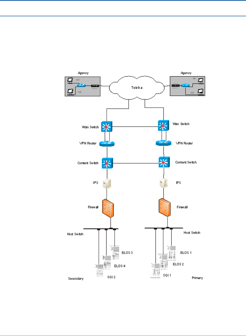
Appendix PAT Technical Manual
8-10 Confidential & Proprietary
8.1 Schematics
8.1.1 Network Schematic
Figure 125: Network Schematic
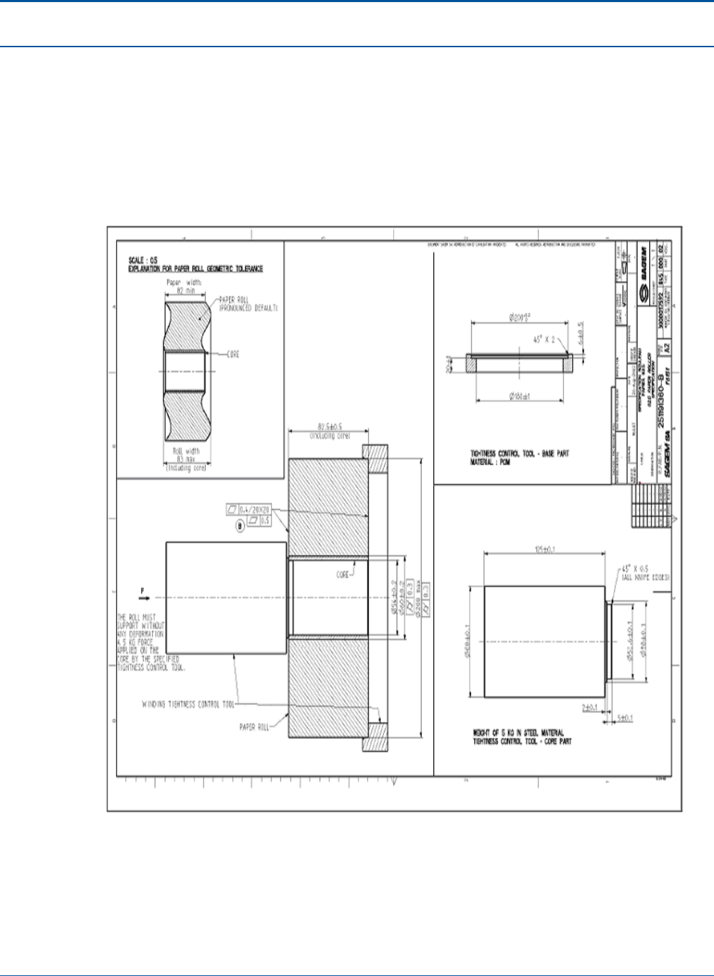
PAT Technical Manual Appendix
Confidential & Proprietary 8-11
8.2 Mechanical Drawings
8.2.1 Paper Roll Specification
Dimensions and tolerances associated with the printer roll are shown in the following
diagram:
Figure 126: Printer Paper Roll Dimensions and Tolerances
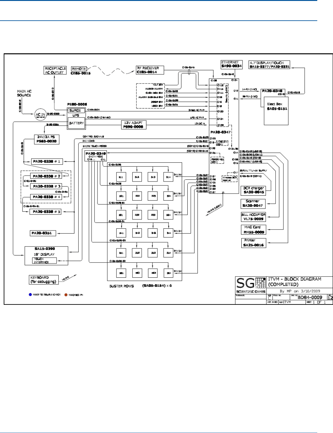
Appendix PAT Technical Manual
8-12 Confidential & Proprietary
8.2.2 PCT Block Diagram
Figure 127: PCT Block Diagram
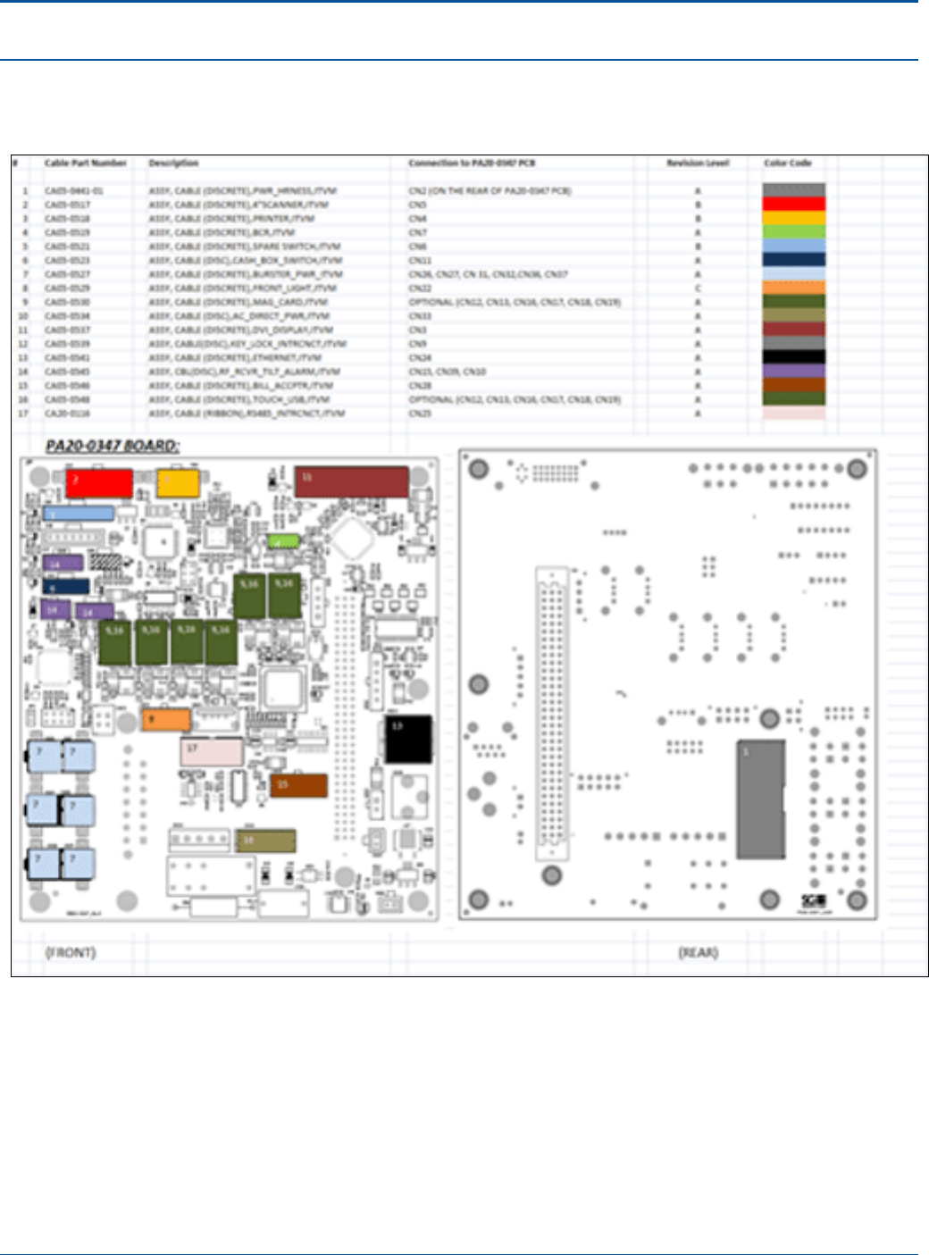
PAT Technical Manual Appendix
Confidential & Proprietary 8-13
8.2.3 Interface Board Wiring Diagram
Figure 128: PCT Interface Board Wiring Diagram
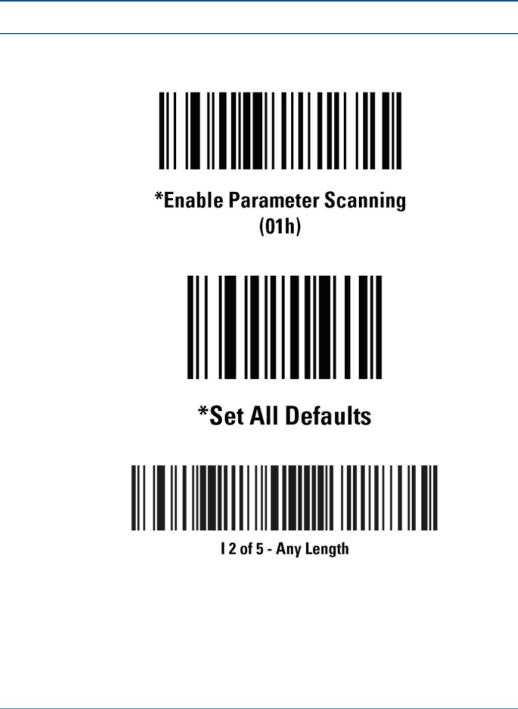
Appendix PAT Technical Manual
8-14 Confidential & Proprietary
8.2.4 Barcode Reader Initialization Functions
Figure 129: Sample Barcode - Enable Parameter Scanning
Figure 130: Sample Barcode - Set All Defaults
Figure 131: Sample Barcode - 12 of 5 – Any Length
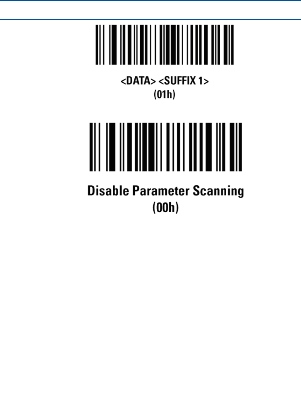
PAT Technical Manual Appendix
Confidential & Proprietary 8-15
Figure 132: Sample Barcode - Data/Suffix
Figure 133: Sample Barcode - Disable Parameter Scanning
9-1 Confidential & Proprietary
SECTION 9
ELECTRONICS TRAY TEST FORM
9.1 Purpose
The following is the electronics tray test form.
THERMALACTIVITYTEST
1min TAT
100% CPU Load PASS (I <60°C) FAIL (I ≥ 60°C)
SIGN HERE → PERFORMED BY: DATE:
VISUALINSPECTION
1. 1. VisualInspection:
FrontofElectronicsTray
PASS FAIL
1.1. CA10‐0104(DualUSB)issecurelyfastenedwith4screws.(ifapplicabledependingonE‐Tray
assembly)
1.2. Retailerdisplayissecure.
1.3. Lockiffunctional.
2. 2. VisualInspection:
Rightsidefacingfront
PASS FAIL
2.1. 4thumbturnssecurelyfastenharddrive.
2.2. ID65‐0044issecuredproperlytoCA05‐0497‐01.
2.3. Powersupplyfanhasairmovingtowardspowersupplyasindicatedbyarrowonfan.
2.4. Groundsaresecurelyfastenedintoplace.
2.5. AllCableconnectionsareproperandsecure.
3. 3. VisualInspection:
Leftsidefacingfront
PASS FAIL
3.1. PA50‐0026‐01(motherboard)issecurelyfastened.
3.2. PA50‐0026‐01(Motherboard)processorfanisdualballbearing.
3.3. Allcablesareproperlydressedandsecuredwithtie‐wrapsaccordingtoreworkinstructions.
3.4. Allcableconnectionsareproperandsecure.
SIGN HERE → PASSED BY: DATE:
POWERONFUNCTIONALINSPECTION
4. 4. PoweronFunctionalinspection:
Biosversion
PASS FAIL
4.1. EnsureBIOSversionisSGI2R027.
4.2. EnsurecorrectdateandtimeandissettoGMT‐5timezone.
5. 5. PoweronFunctionalinspection:
Displays
PASSFAIL
5.1. Retailerdisplayhasvideoandtouchfunctions.
5.2. Maincustomer19”displayhaspropervideoclarity.

Thermal Activity Test Form PAT Technical Manual
9-2 Confidential & Proprietary
5.3. Maincustomer19”displayiscalibratedwith25points.
5.4. Customeradvertisingdisplayhaspropervideoclarity.
6. 6. PoweronFunctionalinspection::
USBPorts
PASSFAIL
6.1. AllUSBportsarefunctional(8or6dependingonE‐Trayversion)
7. 7. PoweronFunctionalinspection:
NetworkPort
PASSFAIL
7.1. Properlycommunicatesthroughnetworkport
8. 8. PoweronFunctionalinspection:
Bursters
PASSFAIL
8.1. ElectronictraycommunicatestoBursters.
9. 9. PoweronFunctionalinspection:
BillAcceptor
PASSFAIL
9.1. BillacceptorcanbeloadedwithproperversionUS51VA71.
10. 10. PoweronFunctionalinspection:
Magneticcardreader
PASSFAIL
10.1. VerifyoperationalwithcorrectreadofMagneticcard.
11. 11. PoweronFunctionalinspection:
DocumentScanner
PASSFAIL
11.1. VerifyscannerishaspropergrayscaleadjustedbyverifyingwithTL20‐0006Rev2.
11.2. Verifyscannerfirmwareversionis1.17.
11.3. ScanprintedDiagnostictesttickets.
11.4. BrandDiagnostictesttickets.
11.5. EnsurePAplayslipisproperlyfeedintoreaderwithforwardejectingenabledtoensureproper
calibration.
12. 12. PoweronFunctionalinspection:
PrinterTest
PASSFAIL
12.1. Verifyprinterfirmwareversionis1.46.
12.2. VerifyDiagnostictestticketsareprinted.
12.3. Withblackstrippaper,verifyproperpaperlowfunction,whenstripchangesfromwhite(paper‐
lowfalse)toblack(paper‐lowtrue).
13. 13. PoweronFunctionalinspection:
Audio
PASSFAIL
13.1. Speakerisfunctionallywithclearaudio.
14. 14. PoweronFunctionalinspection:
BarcodeReader
PASSFAIL
14.1. VerifyBCRCTRL16VER25.
14.2. Properreadofanyofthefollowing:Interleaved2of5withinrangeof12through20digits,Code
39anyticketwithinrangeof9through11digits,DataMatrixbarcode,PDF417barcode.
14.3. PA20‐0347communicatesinwirelessmodewithaSA30‐0045‐02.
15. 15. PoweronFunctionalinspection:
LEDPA20‐0338
PASSFAIL
15.1. LEDfunctionsproperly.
16. 16. PoweronFunctionalinspection:
KeyFob
PASSFAIL
16.1. KeyFobisfunctional

PAT Technical Manual Thermal Activity Test Form
Confidential & Proprietary 9-3
17. 17. PoweronFunctionalinspection:
Switches
PASSFAIL
17.1. VerifySecurityBoardisloadedwithversion2.15.
17.2. VerifyMainDoorreports“DoorLocked”wheninlockedpositionwhenmaindoorisclosedandkey
isremovedfromtheLL73‐0009andhandleispulledupon.
17.3. VerifyMainDoorreport“Doorunlocked”whenkeyisinunlockedposition.
17.4. VerifyDooropen/doorclosed
17.5. NoTilt/Tilt
17.6. CashBoxopened/CashBoxclosed.Verifyswitchreportscorrectlywhenpulleduponwhilein
lockedposition.
SIGN HERE → PASSED BY: DATE:

Confidential & Proprietary Page 1
SECTION 10
APPROVALS
This specification document shall be signed by a representative of the Lottery, the
responsible representative of SGI, and the Software Development Manager (SDM) for
the Jurisdiction.
____________________________________________________________________
IA Representative: Name 1, Title 1} {Date}
____________________________________________________________________
IA Representative: Name 2, Title 2} {Date}
____________________________________________________________________
{SGI Representative: Name 3, Title 3} {Date}
____________________________________________________________________
{SGI Representative: Name 4, Title 4} {Date}
___________________________________________________________________
{Name 5, Title 5} {Date}
____________________________________________________________________
{Name 6, Title 6} {Date}

1500 Bluegrass Lakes Parkway
Alpharetta, Georgia 30004
U.S.A.