ScottCare DCDRX-1 8 Channel Capable, WMTS Receiver. User Manual 503131
ScottCare Corporation 8 Channel Capable, WMTS Receiver. 503131
Contents
- 1. Part15 Page Users Manual
- 2. User Manual
- 3. Service Manual
Service Manual

TeleRehab™ 2004
Service Manual

CARDIOPULMONARY MONITORING SYSTEM
TELEREHAB 2004
Service Manual
Pub. No. PM-39001 (REV8/04)
Copyright © 2004 by The ScottCare Corporation. All rights reserved.
U.S. Patent No. 5,474,090
The ScottCare Corporation
4791 West 150th Street
Cleveland, Ohio 44135
Phone (800) 243-9412
Phone (216) 362-0550
Fax (216) 267-6129
Omniprep™ and Nuprep™ are registered trademarks of
Weaver and Company, 565-C Nucla Way, Aurora, CO 80011

TeleRehab™ 2004 Cardiopulmonary Monitoring System Service Manual
________________________________________________________________________
-i-
PREFACE
DESIGN ................................................................................................................................................... 1
INTENDED USE........................................................................................................................................ 1
DIAGNOSTIC USE WARNING ................................................................................................................... 1
DISCLAIMER OF LIABILITIES.................................................................................................................. 1
FCC PART 15 INFORMATION .................................................................................................................. 2
FCC PART 68 INFORMATION .................................................................................................................. 2
INDUSTRY CANADA INFORMATION ....................................................................................................... 3
IMPORTANT SAFETY INFORMATION...................................................................................................... 4
WARNING: USE OF COMPUTER FOR OTHER SOFTWARE......................................................................... 4
TRANSTELEPHONIC EMERGENCIES ...................................................................................................... 4
ACCIDENTAL DISCONNECTION DURING TRANSTELEPHONIC MONITORING........................................... 4
TELEREHAB 2004 MONITORING SYSTEM
OVERVIEW ............................................................................................................................................. 5
QRS DETECTION ..................................................................................................................................... 5
HEART RATE .......................................................................................................................................... 5
ARRHYTHMIA DETECTION ..................................................................................................................... 6
ARTIFACT............................................................................................................................................... 6
CONTROL OF ARTIFACT ......................................................................................................................... 6
PREPARATION OF THE PATIENT ............................................................................................................. 6
ELECTRODE POSITION ........................................................................................................................... 7
CABLE POSITION .................................................................................................................................... 7
TRANSMITTER/CABLE MOTION.............................................................................................................. 7
OUT OF RANGE OR LOW BATTERY ......................................................................................................... 7
TELEREHAB 2004 HARDWARE CONFIGURATIONS
CONFIGURATION #1 - ONE SERVER WORKSTATION AND ONE MONITOR ............................................... 8
CONFIGURATION #2 - ONE SERVER WORKSTATION AND TWO MONITORS............................................. 8
CONFIGURATION #3 - CONFIGURATION #1 WITH AN ADDITIONAL WORKSTATION ............................... 9
SYSTEM DESCRIPTION............................................................................................................................ 9
TELEMETRY RECEIVERS/TRANSMITTERS ............................................................................................ 11
TELEMETRY INTERFACE BOX (TIB) ..................................................................................................... 11
STRIP CHART RECORDER ..................................................................................................................... 11
PRINTER INTERFACE BOX (PIB)............................................................................................................ 11
TRANSTELEPHONIC BASE STATION...................................................................................................... 11
TRANSTELEPHONIC INTERFACE BOX................................................................................................... 12
NETWORK SWITCH/HUB....................................................................................................................... 12
LASER PRINTER.................................................................................................................................... 12
FILE SERVER WORKSTATION ............................................................................................................... 12

TeleRehab™ 2004 Cardiopulmonary Monitoring System Service Manual
________________________________________________________________________
-ii-
ADDITIONAL WORKSTATION................................................................................................................ 12
PATIENT STATIONS............................................................................................................................... 12
ACCESSORIES ....................................................................................................................................... 13
SOFTWARE PROVIDED.......................................................................................................................... 13
TELEREHAB 2004 SYSTEM INSTALLATION AND MAINTENANCE
EQUIPMENT.......................................................................................................................................... 13
SITE REQUIREMENTS ........................................................................................................................... 14
ELECTRICAL SAFETY ........................................................................................................................... 14
PREPARATION FOR INSTALLATON ....................................................................................................... 14
CONNECTING THE TELEREHAB 2004 SYSTEM
LASER PRINTER.................................................................................................................................... 15
SERVER/WORKSTATION COMPUTERS .................................................................................................. 15
FLAT PANEL MONITORS ....................................................................................................................... 15
TELEMETRY RECEIVERS (ANALOG)..................................................................................................... 15
TELEMETRY RECEIVERS (DIGITAL) ..................................................................................................... 16
STRIP CHART RECORDER ..................................................................................................................... 16
TRANSTELEPHONIC BASE STATION (IF USED) ...................................................................................... 16
NETWORK SWITCH (HUB) .................................................................................................................... 17
SETTING UP A PATIENT STATION.......................................................................................................... 17
SYSTEM SET UP AND CALIBRATION...................................................................................................... 18
CALIBRATION OF THE TOUCH SCREEN ................................................................................................ 18
SET TIME AND DATE ............................................................................................................................. 19
SYSTEM HARDWARE CONFIGURATIONS............................................................................................... 19
SYSTEM OPERATION CHECK ................................................................................................................ 19
IF A SYSTEM IS EQUIPPED FOR TRANSTELEPHONIC MONITORING....................................................... 19
FOR ALL SYSTEMS................................................................................................................................ 20
SETTING UP A TETHERED PATIENT STATION ....................................................................................... 20
SETTING UP A NON-TETHERED PATIENT STATION ............................................................................... 20
DIGITAL TELEMTRY TRANSMITTER - MODEL DS2 ............................................................................... 21
TYPE CF DEFIBRILLATION PROTECTED EQUIPMENT ........................................................................... 21
EXPOSURE TO RADIO FREQUENCY RADIATION .................................................................................... 21
OPERATION OF THE SCOTTCARE DS2 TRANSMITTER
POWER UP ............................................................................................................................................ 21
PATIENT PREPARATION ....................................................................................................................... 22
POWER DOWN ...................................................................................................................................... 22
CARING FOR THE SCOTTCARE DS2....................................................................................................... 22

TeleRehab™ 2004 Cardiopulmonary Monitoring System Service Manual
________________________________________________________________________
-iii-
TROUBLESHOOTING............................................................................................................................. 23
SPECIFICATIONS .................................................................................................................................. 23
INSTALLING SOFTWARE UPDATES
SERVER/WORKSTATION ....................................................................................................................... 24
WORKSTATION MODULE ...................................................................................................................... 25
PREVENTIVE MAINTENANCE
VISUAL INSPECTION ............................................................................................................................. 25
ELECTRICAL SAFETY ........................................................................................................................... 25
PERFORMANCE TESTING...................................................................................................................... 26
CARE AND CLEANING ........................................................................................................................... 26
TROUBLESHOOTING
SYSTEM OPERATIONAL PROBLEMS...................................................................................................... 27
CONTROL OF ARTIFACT ....................................................................................................................... 27
2004 TROUBLESHOOTING GUIDE
SYSTEM DOES NOT COME UP (NO CRT DISPLAY).................................................................................. 28
SYSTEM BOOTS UP BUT FAILS TO GET TO WINDOWS DESKTOP............................................................ 29
TOUCHSCREEN ERRATIC OR OTHERWISE DOES NOT WORK CORRECTLY ........................................... 29
SYSTEM LOCKS UP DURING MONITORING............................................................................................ 29
UNABLE TO START THE 2004 PROGRAM .............................................................................................. 30
MONITORING SOFTWARE DISPLAYS CORRECTLY, BUT TRACES WILL NOT START .............................. 30
TCP/IP ERROR-RECEIVER MODULE NOT RESPONDING /LOSS OF REMOTE ........................................... 31
CHECK LEADS MESSAGE APPEARS ON A MONITORING CHANNEL (DIGITAL ONLY .............................. 31
CHECK BATTERY MESSAGE APPEARS ON A MONITORING CHANNEL (DIGITAL ONLY) ........................ 31
STRIP CHART RECORDER WILL NOT PRINT A STRIP............................................................................. 32
UNABLE TO PRINT TO SCOTTCARE NETWORK LASER PRINTER ........................................................... 32
UNABLE TO BACK UP FILES TO THE ZIP DRIVE..................................................................................... 32
TELEREHAB 2004 SPECIFICATIONS
MONITORING/SERVER WORKSTATION................................................................................................. 33
FLAT PANEL MONITOR ......................................................................................................................... 33
FLAT PANEL TOUCHSCREEN ................................................................................................................ 34
STRIP CHART RECORDER ..................................................................................................................... 34
NETWORK PRINTER.............................................................................................................................. 34
DATA STORAGE .................................................................................................................................... 35
TRANSMITTER (DIGITAL)..................................................................................................................... 35
RECEIVER BASE TECHNICAL INFORMATION (DIGITAL)....................................................................... 36
TeleRehab™ 2004 Cardiopulmonary Monitoring System Service Manual
________________________________________________________________________
-iv-
ECG TELEMETRY TRANSMITTER (ANALOG) ........................................................................................ 37
ECG CHANNEL RELATED (ANALOG)..................................................................................................... 37
TELEMETRY RECEIVER UNIT (ANALOG) .............................................................................................. 38
TELEMETRY ANTENNA......................................................................................................................... 38
MOUNTING ........................................................................................................................................... 38
FDA APPROVALS/CERTIFICATIONS ...................................................................................................... 38
TYPICAL TCP/IP ADDRESSES USED FOR TELEREHAB 2004 COMPONENTS............................................ 39
TeleRehab™ 2004 Cardiopulmonary Monitoring System Service Manual
________________________________________________________________________
-1-
PREFACE
Design
The ScottCare TeleRehab 2004 Cardiopulmonary Monitoring System is designed to allow
monitoring and recording of electrocardiograph (ECG) rhythm strips and related information for
patients undergoing an exercise therapy program. Patients are monitored via the use of medical
telemetry. The TeleRehab 2004 Cardiopulmonary Monitoring System includes a Program
Management module that provides the means to print reports of exercise sessions, cumulative
patient progress, and compliance.
Intended Use
The ScottCare TeleRehab 2004 Cardiopulmonary Monitoring System is intended for use as a
group rhythm strip-monitoring device for cardiac rehabilitation patients. The system is
comprised of the computerized central unit located at the monitoring site, and the RF
transmitting equipment.
The RF transmitting equipment is intended for use by a cardiac rehabilitation patient enrolled in
a group rhythm strip-monitoring program. These transmitters are only to be used under the
instruction and supervision of qualified personnel. Federal law restricts this device to sale by
or on the order of a physician. (Qualified personnel are defined as hospital or clinical
personnel that have been trained in the proper application and use of this equipment).
Diagnostic Use Warning
ScottCare Patient Equipment is designed to amplify and process rhythm strips. The shape of
transmitted ECG waveforms may be affected by body movement causing intermittent electrode
contact or by other factors external to the Transmitter module. ACCORDINGLY, SCOTTCARE
MAKES NO CLAIMS OR WARRANTIES, EXPRESS OR IMPLIED (INCLUDING
WARRANTIES OF MERCHANTABILITY AND FITNESS FOR A PARTICULAR
PURPOSE), AS TO THE QUALITY OF THE ECG SIGNAL RECEIVED, OR AS TO ITS
EFFECTIVENESS AS A DIAGNOSTIC TOOL.

TeleRehab™ 2004 Cardiopulmonary Monitoring System Service Manual
________________________________________________________________________
-2-
System Limitations:
The ScottCare TeleRehab Advantage monitoring system is capable of multi tasking, however, as
with all computer systems, there are limitations. Changes to the TeleRehab Advantage
configuration files should not be accomplished if any component of the system is in use, whether
a monitoring terminal or a work station being utilized for use of the program management
applications.
The ScottCare TeleRehab Advantage monitoring system is designed to extensively utilize the
multi tasking capabilities of the Windows XP Professional operating system. As a result, it is
possible that events may occur that cause what appear to be software anomalies that, in reality,
are a result of the interaction between the Advantage system software and the operating system.
Although rare, these idiosyncrasies can be a source of frustration for the equipment operator.
Examples include:
• When using the mouse and/or touchscreen to provide manipulation of the
Advantage system, it is possible to provide commands via clicking of the mouse
or touching of the touch screen monitor, faster than the system can respond. In a
small number of cases, the operating system will overload with a backup of input
commands producing undesirable results. Although the software has been
‘hardened’ to ignore commands when an too many commands are backed up,
system crashes are still a possibility.
To avoid these undesirable results, one should be patient when manipulating the
Advantage system, and not provide a new command until the last command has
been satisfied.
• It is possible for the interaction between the Advantage software and the
operating system to cause the random discontinuation of the recording of one or
more sessions when monitoring several patients at once. The Advantage system
continuously checks the recording function to verify that the recording of each
session is taking place. When a discontinuation occurs, the system will provide
notification as follows:
TeleRehab™ 2004 Cardiopulmonary Monitoring System Service Manual
________________________________________________________________________
-3-
If you wish to continue monitoring without recording, left click on the ‘Cancel’
button.
If left clicking on the ‘Retry’ button only results in this window being displayed
again, call ScottCare customer service (800-243-9412) for assistance.
Disclaimer of Liabilities
The ScottCare Corporation, its parent, affiliates, agents, officers and employees, shall not be
liable for special, incidental, or consequential loss or damages of any kind resulting from or
caused by any defect, failure or malfunctioning of the equipment described herein, whether a
claim for such loss or damages is based upon warranty, contract or otherwise. The ECG
Transmitter/Receiver system, manufactured by The ScottCare Corporation, is designed to
amplify and transmit Rhythm Strips. THE SCOTTCARE CORPORATION MAKES NO
CLAIMS OR WARRANTIES, EXPRESS OR IMPLIED (INCLUDING WARRANTIES OF
MERCHANTABILITY AND FITNESS FOR A PARTICULAR PURPOSE) AS TO ITS
EFFECTIVENESS AS A DIAGNOSTIC, LIFE SAVING OR LIFE SUPPORT TOOL.
FCC Part 15 Information
The Telemetry Transmitter provided complies with the limits for a biomedical telemetry device
pursuant to Part 15 of the FCC Rules. These limits are designed to provide reasonable protection
against harmful interference in a residential installation.
Operation of the Telemetry equipment is subject to the following two conditions:
1. The Telemetry Transmitter may not cause harmful interference.
2. The Telemetry Transmitter must accept any interference received, including
interference that may cause undesired operation.
Any changes or modification not expressly approved by ScottCare could void the user’s
authority to operate the telemetry equipment.
TeleRehab™ 2004 Cardiopulmonary Monitoring System Service Manual
________________________________________________________________________
-4-
The ScottCare Corporation
4791 West 150th Street
Cleveland, OH 44135
(216) 362-0550
(800) 243-9412
Important Safety Information
Read all of these instructions before operating the equipment, and save these instructions for
later reference. There are many instructions that relate to your safety.
WARNING: Use of Computer for Other Software
The Computer(s) used with the Tele-Rehab 2004 Cardiopulmonary Monitoring System have excess
capacity that might be used to run other software applications. It should be noted that the installation
and use of software or hardware other than that installed by ScottCare might compromise system
performance or cause system failure. ScottCare recommends against using any workstation as a common
computer, and is not responsible for any problems or system failure caused by use of other software not
expressly approved in writing by ScottCare for use on its systems.
TeleRehab™ 2004 Cardiopulmonary Monitoring System Service Manual
________________________________________________________________________
-5-
TELEREHAB 2004 MONITORING SYSTEM
Overview
The ScottCare TeleRehab Monitoring System Software is a comprehensive software package for
use on the TeleRehab 2004 computer based cardiopulmonary monitoring system designed to
provide monitoring capability specifically for patients involved in an exercise schedule
prescribed as a part of a cardiac or pulmonary rehabilitation program. Monitoring takes place
while the patient exercises locally within an exercise facility via the use of telemetry.
QRS Detection
The TeleRehab 2004 Monitoring System software detects QRS complexes in accordance with
the AAMI standard for Cardiac Monitors, Heart Rate Meters and Alarms (EC-13).
Heart Rate
The TeleRehab™ 2004 Monitoring System software detects the patient heart rate by counting
TeleRehab™ 2004 Cardiopulmonary Monitoring System Service Manual
________________________________________________________________________
-6-
the QRS complexes detected and displaying a running average of the last four (4) intervals.
Sampling occurs constantly and the display is adjusted with each interval. If the patient’s heart
rate exceeds a prescribed high limit value or drops below a prescribed low limit value, the QRS
complex and rate indication will turn RED and an alarm will sound to alert the system operator
that the rate limit has been violated.
Arrhythmia Detection
Rate related arrhythmias generally create a change in the R-to-R interval that is detectable by the
system. As the Tele-Rehab 2004 Monitoring System software monitors the interval between
QRS complexes, a change in R-to-R interval of greater than 25% will cause the displayed QRS
complex to turn blue and an alarm to sound to alert the system operator that an event has
occurred that might require attention. Rates displayed while the heart rate indicator is blue will
not be accurate heart rates.
Artifact
In order for the heart rate detection system and arrhythmia detection systems to perform at
optimum efficiency, artifact must be minimized. Detected intervals that make no sense to the
system will cause the display grid and rate indication to turn orange. Rates displayed while the
display is orange will not be accurate. Some forms of artifact are of a type that will be detected
by the system as potential arrhythmia in which case the QRS complex will turn blue and a soft
alarm will sound giving a false indication of arrhythmia. Rates displayed while the QRS complex
is blue will not be accurate.
Control of Artifact
It is essential that artifact be minimized to keep from interfering with the monitoring of the
exercising patient. Some types of artifact can cause the system to react as though it were seeing
ectopy, and other types cause the system to identify as erroneous, data generated when artifact is
detected. In general, artifact can be controlled. There is always the patient who generates artifact
no matter what you do; however, those are normally few and far between.
Several parameters can be involved in the production of artifact. Following are some causes and
cures:
Preparation of the Patient - The greatest cause of artifact is inadequate contact between the
patient and the electrodes. This condition is evident when artifact disappears when the
transmitter is attached to a patient simulator where optimum contact is assured. Some causes of
inadequate contact include the use of outdated pre-gelled electrodes where the conducting
medium is dried out, or inadequate preparation of the area where the electrode is to be placed.
TeleRehab™ 2004 Cardiopulmonary Monitoring System Service Manual
________________________________________________________________________
-7-
Alcohol is a commonly used means of patient prep. Although alcohol kills bacteria and cleans
the area, alcohol tends to dry out the skin thereby increasing the skins electrical resistance.
Roughing the area by rubbing with a gauze pad or terry cloth towel often helps to reduce skin
resistance when alcohol is to be used as the prep medium.
The best prep is usually done for stress test patients and is normally extensive in that the skin is
severely stressed before application of electrodes.
ScottCare recommends that a commercially available prep medium such as "Omniprep™" or
"Nuprep™" be used with the cardiopulmonary rehab patient. When adequately prepped, artifact
is rarely a problem.
Electrode Position - Often electrodes are placed on the patient’s chest area over the pectoral
muscle and/or over the soft area under the rib cage. Artifact is then created when the patient
exercises due to the contraction of the pectoral muscle.
ScottCare recommends that electrodes be placed above the pectoral muscle just under the
clavicle for the right arm and left arm leads, and on the lower rib area for the Left Leg and/or
Right Leg lead. This placement will not normally have a significant effect the QRS complex but
will eliminate motion artifact caused by muscle movement.
Cable Position - Patient Cables are frequently run from the patient transmitter, under the shirt,
to the electrode site. When the lead wires are against the skin, it is possible for artifact to be
introduced due to the rubbing of the wire against the skin during exercise.
ScottCare recommends that wires be run in such a manner as to minimize contact between the
skin and the patient lead wire.
Transmitter/Cable Motion – Transmitters are provided with belt clips and can be worn on the
belt line, placed in a pocket, placed in a pouch, or worn wherever comfortable and well
supported. Transmitters that are not well supported can move about freely which can create
motion artifact.
ScottCare recommends that transmitters be attached to the belt line off the hip to the rear in order
to minimize jostling by the leg during exercise. If a pouch is used, it should be secured to the
patient in a location least susceptible to jarring during exercise such as the center of the upper
chest area.
TeleRehab™ 2004 Cardiopulmonary Monitoring System Service Manual
________________________________________________________________________
-8-
Out of Range or Low Battery – Depending upon the specific type of transmitter in use,
transmitter range is approximately 100 feet depending upon the environment and what material
is between the transmitter and receiver. If the patient is “out of range” or if the battery voltage
drops below an acceptable level, the QRS signal will be diminished and may be over written by
artifact. Normal battery life is approximately 70 hours. When artifact appears as though the
transmitter is not connected, try changing the battery and patient lead in that order. If artifact
persists, call ScottCare for assistance. Refer to the section in the service manual regarding the
specific transmitter in use for more information.
TeleRehab™ 2004 Cardiopulmonary Monitoring System Service Manual
________________________________________________________________________
-9-
HARDWARE CONFIGURATIONS
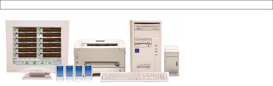
Configuration #1 - One Server Workstation and one monitor.
Standard configuration includes:
1 Windows XP Server Workstation with 2004 Software
1 Flat Panel, Touchscreen Monitor with Integrated Speakers
1 Receiver Module with Antenna (not shown)
2 Digital Telemetry Interface Box (DTIB1 and DTIB2) not shown
1-16 Telemetry Channels with 608-614 MHz Digital Transmitters
1 Strip Chart Recorder
1 Printer Interface Box (PIB)
1 Network Laser Printer
TeleRehab™ 2004 Cardiopulmonary Monitoring System Service Manual
________________________________________________________________________
-10-
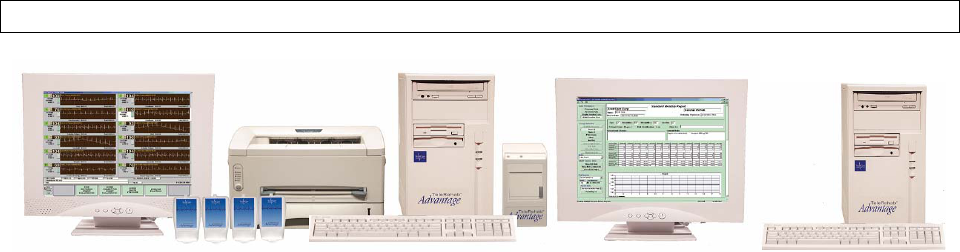
Configuration #2 – Configuration #1 with an additional workstation.
Standard configuration includes:
1 Windows XP Server Workstation with 2004 Software
1 Windows XP Workstation with 2004 Software
2 Flat Panel, Touchscreen Monitor with Integrated Speakers
1 Receiver Module with Antenna (not shown)
2 Digital Telemetry Interface Box (DTIB1 and DTIB2) not shown
1-16 Telemetry Channels with 608-614 MHz Digital Transmitters
1 Strip Chart Recorder
1 Printer Interface Box (PIB)
1 Network Laser Printer
System Description
The TeleRehab 2004 Monitoring System is an ECG monitoring system with the capability of
monitoring up to sixteen channels of data simultaneously on one workstation. The system also maintains
and processes a myriad of data regarding patients participating in the Cardiopulmonary Rehabilitation
Program.
The system receives the patients ECG signal from up to sixteen patient worn radio frequency (RF)
telemetry transmitters. ECG signals are received by the RF receiver module and coupled through the
telemetry interface box to the workstation via the network HUB where the signals are then processed and
displayed on the SVGA Monitor. The monitoring system is operated either through the use of a
touchscreen installed as a part of the SVGA monitor, a mouse, or a standard computer keyboard. A
thermal array printer is employed to provide a hard copy of the displayed rhythm strip on command.
The 2004 File Server workstation employs the File Server software to function as the network controller.
The workstation also functions as the repository of all data regarding patients seen by the monitoring
system. A laser printer is provided to generate reports applicable to the cardiac rehabilitation
environment.

TeleRehab™ 2004 Cardiopulmonary Monitoring System Service Manual
________________________________________________________________________
-11-
Telemetry
Receivers
Transtel Base
Station
Strip Chart
Recorder
Telemetry
Interface Box
(TIB)
Network Switch/HUB
Transtel
Interface Box
File Server/
Workstation
Additional
Workstation Laser Printer
Printer
Interface Box
(PIB)
Telemetry Receivers/Transmitters
The TeleRehab 2004 system is designed to utilize either analog or digital transmitter/receivers in the
608–614 MHz range.
Analog transmitters are not tunable and generally not field serviceable, although mechanical parts are
available and easily replaced. ScottCare employs an exchange program at reasonable cost to facilitate
speed and accuracy of repair. Likewise, receiver cards are available on an exchange.
Digital transmitters being waterproof and therefore sealed units are not field repairable. Exchange
units are readily available through ScottCare service. Digital transmitters are tunable to various
frequencies in the 608-614 MHz range through the use of calibration material available from
ScottCare.
TeleRehab™ 2004 Cardiopulmonary Monitoring System Service Manual
________________________________________________________________________
-12-
Digital Receiver cards are designed to include 2 receivers on each circuit board. These receivers, as with
others, are not field serviceable and can be exchanged when found to be defective.
Telemetry Interface Box(s) (TIB)
The Telemetry Interface Box contains the electronics needed to convert the method of
communication of the telemetry signal from RS232 technology to TCP/IP technology. The firmware
is programmed at the factory and is not changeable in the field with the exception of setting up the
frequencies for the receiver modules. A computer with specific software is required to change
receiver frequencies.
Strip Chart Recorder
The Strip Chart Recorder is a stand alone Thermal Array Printer manufactured by GSI Lumonics. It
uses standard thermal strip paper.
Printer Interface Box (PIB)
The Printer Interface Box (PIB) contains the electronics needed to convert the method of
communication of rhythm strip information from RS232 technology to TCP/IP technology. The
firmware is programmed at the factory and is not programmable in the field.
Network Switch/HUB
The Network Switch/HUB is the device that allows communication between all of the components of
the system. Each component is attached to the network switch through CAT5 cable connections.
Laser Printer
The Laser Printer is supplied to provide “hard copy” data concerning a patient’s activity. It is a
standard laser printer that uses TCP/IP communication technology to receive information regarding
reports as processed by a workstation.
File Server Workstation
The File Server Workstation is the heart of the system consisting of a computer with a proprietary
data base application that allows storage of patient information including session data. The File
Server application that controls patient lists and schedules, and the Program Management and
Monitoring application software as well as Outcomes software also reside on this computer. The
Monitor used with the File Server Workstation can be a 17” or 19” SVGA color flat panel, which
TeleRehab™ 2004 Cardiopulmonary Monitoring System Service Manual
________________________________________________________________________
-13-
may or may not be equipped with a touch screen.
Additional Workstation
The optional Additional Workstation consists of a computer with Outcomes, Program Management
and Monitoring application software resident. The Monitor used with the Additional Workstation can
be a 17” or 19” SVGA color flat panel, which may or may not be equipped with a touch screen.
Accessories
Battery, 9V, Alkaline (analog transmitters)
Battery, 1.5V AAA, Alkaline (digital transmitters)
Patient Lead Set, 2-wire Alligator Clip or Dot Snap (analog transmitters)
ANSI/AAMI DIN style shielded lead wire set (digital Transmitters)
Chart Paper, Recorder
Zip Disks (250MB)
Base Station Headset
Telemetry Antenna
Telephone Cables
Telemetry Cable
Receiver Power Supply, 9 Volt
Transtelephonic RS232 Cable
Transtelephonic Voice Cable
Software Provided
Windows XP
TeleRehab 2004 Monitoring System Software
Outcomes Software.
INSTALLATION AND MAINTENANCE
Equipment
The TeleRehab 2004 Monitoring System consists of a combination of the previously listed
components optimized to meet the needs of the customer. The number of telemetry channels will vary
from 0 to 16 for each monitoring.
TeleRehab™ 2004 Cardiopulmonary Monitoring System Service Manual
________________________________________________________________________
-14-
Site Requirements
The TeleRehab 2004 Monitoring System is typically located at a nurse’s station or at a cardiac rehab
monitoring station. The monitoring system may rest on a table or a shelf at a height and position for easy
viewing and operation of both the keyboard and touchscreen. Any components placed on the floor should
be placed so they are not subject to inadvertent contact.
The 2004 Data Management System can be co-located with the monitoring terminal either on the same
computer or as an additional workstation. An additional workstation can be located in an office or other
location more convenient to operating personnel. Connection is made between the server workstation and
the other components via CAT5 cables and a Network Switch/Hub.
All computers and laser printer are equipped with exhaust fans for cooling. The monitoring system
should be installed allowing a minimum of two inches airspace at the rear, top and both sides of the
computers, flat panel monitors and laser printer to allow for adequate ventilation and cooling. If the
system is to be installed into a console, the console must be designed to provide for adequate ventilation
and cooling.
115 Volt 60 Hz electrical outlets should be provided for each component.
Electrical Safety
Major components of the TeleRehab 2004 Monitoring System are equipped with approved 3-wire line
cords and meet leakage current specifications for office type equipment, and the system as a whole has
UL or ETL approval.
Electrical Safety testing should be in accordance with NFPA 99, and all interconnecting cables should be
in place when testing is performed.
If electrical outlets controlled from a central switch are not provided and an outlet strip is used to power
the various components of the system, it may be necessary to affix a redundant ground wire to the system
or provide an isolation transformer.
Preparation for Installation
Before interconnecting the individual components of the system, an equipment configuration should be
decided upon. The system components can be positioned in many different ways allowing for installation
TeleRehab™ 2004 Cardiopulmonary Monitoring System Service Manual
________________________________________________________________________
-15-
in various space allocations. The toner cartridge should be installed in the laser printer in accordance with
the manufacturers instructions.
CONNECTING THE TELEREHAB 2004 SYSTEM
Laser Printer
• Connect the Laser Printer network cable to the network switch/hub.
• Connect the Laser Printer Power Cord to the power connector on the rear of the Laser Printer,
then to the Power Outlet.
Server/Workstation Computers
• Connect the Windows XP Server/Workstation power cord to the power connector at the rear
of the unit, then to an acceptable power outlet. Install a CAT5 cable between the RJ45 port
on the back of the Server/Workstation Computer and the network switch/hub.
• Plug the keyboard cable into the jack provided on the rear of the PC.
• Plug the mouse cable into the jack provided on the rear of the PC.
• Connect the Modem phone cable to the RJ11 connector on the back of the
Server/Workstation computer and to the external RJ11 phone jack providing availability of
an analog phone line to the computer for use with the pcAnywhere application.
Flat Panel Monitors
• Connect the Touchscreen Cable if present, to the serial port labeled “Touchscreen” at the rear
of the Windows XP Server/Workstation.
• Connect the SVGA Cable to the DB15 Connector labeled “Monitor” at the rear of the
Windows XP Server/Workstation.
• Connect the flat panel monitor power cord to the power connector at the rear of the flat panel
monitor, then to the power outlet
• Connect the speaker cables between the Flat Panel Monitor and the audio output jack on the
back of the File Server/Workstation Computer. (Note: Some monitors may not have built in
speakers in which case separate speakers will be provided.)
TeleRehab™ 2004 Cardiopulmonary Monitoring System Service Manual
________________________________________________________________________
-16-
Telemetry Receivers (Analog)
• Connect the Telemetry Cable between the DB9 connector at the rear of the telemetry receiver
module and the DB9 connector at the rear of the Telemetry Interface Box (TIB). Plug the
telemetry receiver module power cable into an acceptable power outlet. Connect the TIB box
to the network switch/hub with the CAT5 cable. Attach the AC adapter to the TIB box and
plug into an acceptable power outlet. If system has more than eight channels, and therefore
requires a secondary TIB box, attach the TIB2 box to the TIB box using the supplied serial
cable being sure to also attach the AC adapter to the TIB2 box and plugging it in to an
acceptable power outlet.
• Connect the antenna wire attached to the telemetry antenna to the SO-239 jack provided at
the rear of each receiver module. The antenna should be placed at least 12” away from the
receiver box. Avoid coiling the antenna wires to cut down on the possibility of interference
caused by magnetic fields.
Telemetry Receivers (Digital)
• Connect a CAT5 Cable from the RJ45 connector on the Receiver Box to the network
switch/hub. Connect the Receiver Box Power Cable to an acceptable power outlet. The
power supply required for the receiver is a Volgen, Model SPU15A-3, Listed ITE Power
Supply.
Strip Chart Recorder
• Connect the serial cable between the DB9 connector on the Strip Chart Recorder and the
DB9 Connector on the Printer Interface Box (PIB). Attach the AC adapter to the Strip Chart
Recorder and plug into an acceptable power outlet.
• Connect a CAT5 Cable from the RJ45 Connector on the Printer Interface Box to the network
switch/hub. Attach the AC adapter to the Printer Interface Box and plug into an acceptable
power outlet.
Network Switch/Hub
• Plug the AC adapter into the back of the network switch/hub, and then plug the other end into
an approved electrical outlet.
System Set Up and Calibration
• Turn each individual power switch to the on position. Upon power-up, the Windows XP

TeleRehab™ 2004 Cardiopulmonary Monitoring System Service Manual
________________________________________________________________________
-17-
Server/Workstation will perform a self-test, while the laser printer will begin its warm-up
period. If the systems self tests are satisfactory, the system software will automatically boot, and
the desktop screen will be displayed (unless changed at initial installation). If the systems self
tests are unsatisfactory, an error message will be displayed on the screen. Record the error
message and try to correct the problem. Contact the Service Department for assistance if you are
unsuccessful. Start the TeleRehab 2004 Program by double-clicking the 2004 Icon on the
desktop. The 2004 Splash screen will be displayed as below.
Calibration of the Touch Screen
• From the Server’s desktop, double-touch the Touchware icon to start the calibration software.
Follow the onscreen prompts to calibrate.
• Close the Touchware window when finished, then double-click the 2004 Server and 2004
software icons to restart the program.
• Verify that the various screens can be selected either by using the touchscreen, or through use of
the keyboard function keys.
Set Time and Date
• The 2004 software will update its time and date information using the Microsoft Windows set
date and time. Therefore, to change its time and date, first change that data in MS Windows.
System Hardware Configuration
TeleRehab™ 2004 Cardiopulmonary Monitoring System Service Manual
________________________________________________________________________
-18-
System Configuration is pre-set at the factory and should not be changed without direction from
the ScottCare Corporation. Call 1-800-243-9412 for assistance.
System Operation Check
Refer to the Operators Manual for the different functions, menu selections, and report data format.
From the 2004 Splash Screen, click the Monitoring button. Install battery(s) in each telemetry
transmitter and attach patient leads to an ECG simulator. Put a name (Scott Care, e.g.) on the
screen for each channel and start the display. Activate the strip chart recorder to verify proper
calibration and operation. Verify that the QRS is accurately detected, recorded and displayed in
accordance with the applicable parts of AAMI/ANSI standard EC-13 and an acceptable QRS is
displayed on the monitor.
For All Systems
• Using a patient simulator and either a telemetry unit or patient kit, set up and record a session with a
minimum duration of 10 minutes. Be sure to go through each step and verify that the touchscreen,
function keys, and software function properly. Verify that the high and low alarms operate, and that
the heart rate displayed is within two beats of actual.
• Generate a full session report and verify that all of the various parameters are accurately reported.
• Using the pre-generated "Scott Care" data, generate monthly, 36 sessions, and compliance reports
and verify that all of the various reports are properly produced.
Digital Telemetry Transmitter, Model DS2
The ScottCare DS2 telemetry transmitter is intended only as an adjunct to patient assessment. It
cannot replace skilled nursing care and proper surveillance. Carefully read this operator’s manual, all
directions for use of the ScottCare 2004 cardiopulmonary monitoring system, and all precautionary
information before attempting clinical use of the transmitter. Always keep high-risk patients under
close surveillance. The information in this document is subject to change without notice.
Type CF Defibrillation Protected Equipment
Isolated patient connections comply with allowable leakage current limits for direct cardiac
application and are protected against effects of defibrillation. Does not contain latex.
TeleRehab™ 2004 Cardiopulmonary Monitoring System Service Manual
________________________________________________________________________
-19-
Exposure to Radio Frequency Radiation
The radiated output power of the internal wireless radio is far below the FCC radio frequency
exposure limits.
OPERATION OF THE SCOTTCARE DS2 TRANSMITTER
Power Up
The ScottCare DS2 transmitter will activate upon placement of three 1.5V AAA alkaline batteries
into battery compartment and turning the knob on battery cover to the ON position. Placement of
batteries and turning the knob to ON automatically enables the telemetry receiver.
CAUTION: To avoid damage to transmitter, use only 1.5V AAA alkaline batteries.
To install batteries and activate transmitter:
1. Access battery compartment by turning the knob on battery cover counterclockwise until the cover
can be removed.
2. Install batteries (noting correct polarity), install battery cover and turn the knob clockwise until
snug (Do not over tighten).
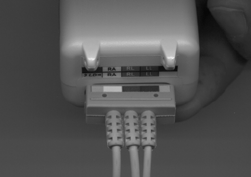
3. Connect the patient cables to the transmitter by plugging the connection block into the receptacle
in the top of the transmitter. Be sure to align the color-coded ports (See picture below).
Patient Preparation
Proper skin prep and electrode placement is critical to ensure patient safety and accurate readings.
1. SCOTTCARE recommends that a commercially available prep medium such as "Omniprep" or
"Nuprep" be used with the cardiac rehab patient. When adequately prepped, artifact is rarely a
problem. (NOTE: Omniprep and Nuprep are registered trademarks of Weaver and Company,
565-C Nucla Way, Aurora, CO 80011).
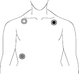
2. Attach lead wires to electrodes before applying electrodes to patient.
3. Apply electrodes to skin, pressing firmly around entire edge of adhesive surface (refer to the
illustration below for lead placement).
4. Ensure electrodes are placed in proper locations.
TeleRehab™ 2004 Cardiopulmonary Monitoring System Service Manual
________________________________________________________________________
-20-
5. Confirm appropriate alarm status and limits exist for patient based on clinical assessment.
whi t e
red
bl ack
Power Down
Discontinuation of the ScottCare DS2 transmitter requires that all leads and cables be removed from
patient. Scottcare DS2’s power remains on while batteries are in battery compartment and the
battery cover is in place. Remove batteries from the ScottCare DS2 for overnight storage or nonuse.
Caring for the ScottCare DS2
For cleaning, use only a lint-free, nonabrasive cloth, which has been slightly dampened with mild
detergent, a glass cleaner, or a non-alcoholic based solvent.
Avoid harsh cleaning solutions such as isopropyl alcohol or other solvents that might harm plastic
surfaces. Avoid anti-bacterial cleaning solutions, especially those containing Phenol. Do not spray
liquids directly on the DS2.
Do not allow liquids to penetrate connectors or the DS2's case.
Troubleshooting
Excessive noise or artifact on display….Check skin prep. Check electrodes. Placement may be
causing motion pick-up. Signal loss…. Electrode is lost or disconnected. ScottCare DS2 telemetry
is not displayed at the monitoring terminal…. Replace batteries. Ensure battery cover switch is in the
TeleRehab™ 2004 Cardiopulmonary Monitoring System Service Manual
________________________________________________________________________
-21-
"ON" position. Confirm the transmitter channel is the channel selected at the monitoring station.
Specifications
Physical
Size: 4.6 x 2.0 x 1.3 inches (HWD)
Weight: 3.7 oz less batteries, 5.0 oz with batteries
RF Characteristics
Transmission type: Digital
Frequency range: 608 – 614 MHz WMTS band
Frequency tolerance: Plus or minus 5 ppm
Output power: 5dbm
ECG
Leads transmitted: Lead II, V
Number of electrodes: 3 or 5
Leads transmitted simultaneously: 2
Input impedance (megohms): >20
Frequency response (Hz): 0.05 – 100
Pacer ID: Yes, 2mV to 700mV, 100usec. To 2msec.
Dynamic range: Plus or minus 5mV
DC Offset: Plus or minus 400mV
Common Mode Rejection Ratio: 80db @ 60Hz minimum
Defibrillation Recovery Time: within 8 seconds
Power
Battery type: 3-1.5V AAA, Alkaline
Battery life (days): Minimum 3 days with alkaline battery
Reverse battery protection: Yes
Low battery signal: Yes
Environmental
Temperature range: 10 – 40 degrees Celsius
Humidity range: 15% - 95% relative humidity
TeleRehab™ 2004 Cardiopulmonary Monitoring System Service Manual
________________________________________________________________________
-22-
INSTALLING SOFTWARE UPDATES
Follow these procedures for all Scottcare 2004 updates. Note that there is only one
Server/Workstation. This is the system that contains the 2004 Server software. All other units
are referred to as workstations only.
You need to edit and print all current session reports and run the back-up utility.
If you have any problems, or otherwise need help with the installation, please call us at 1-800-243-
9412 Option 2. We will be happy to assist you.
Note: To upgrade your SERVER computer, you need to do the following:
Step 1 To upgrade Advantage Server Software, ensure that no other programs are running at
the bottom of the screen to the right of the windows START button. I.E. [ScottCare TCP/IP
Ser…]
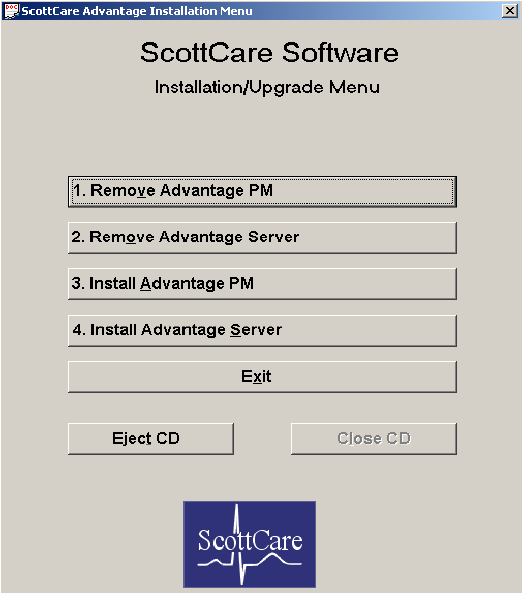
Step 2 Insert your upgrade CD-ROM into your system’s CD tray. The software will
AUTORUN and display the program screen shown in figure 1 on page 2.
Step 3 Click the [1. Remove Advantage PM] button on the program screen. Follow the
onscreen prompts using all default options.
Step 4 When that removal is complete, click the [2. Remove Advantage Server] button on the
program screen. Again, follow the onscreen prompts using all default options.
Step 5 When that removal is complete, click the [3. Install Advantage PM] button on the
program screen. Follow the onscreen prompts using all default options.
Step 6 When that installation is complete, click the [4. Install Advantage Server] button on
the program screen. Follow the onscreen prompts using all default options.
Step 7 When that installation is complete, click the [Eject CD] button, then the [Exit] button.
Software upgrade is complete.
TeleRehab™ 2004 Cardiopulmonary Monitoring System Service Manual
________________________________________________________________________
-23-
Note: To upgrade each of your WORKSTATION computers, you need to do the following:
Step 1 To upgrade Advantage Program Software, ensure that no other programs are running at the
bottom of the screen to the right of the windows START button. I.E. [ScottCare TCP/IP Ser…]
Step 2 Insert your upgrade CD-ROM into your system’s CD tray. The software will AUTORUN and
display the program screen shown in figure 1 on page 2.
Step 3 Click the [1. Remove Advantage PM] button on the program screen. Follow the onscreen
prompts using all default options.
Step 4 When that removal is complete, click the [3. Install Advantage PM] button on the program
screen. Follow the onscreen prompts using all default options.
Step 5 When that installation is complete, click the [Eject CD] button, then the [Exit] button. Software
upgrade is complete.
Figure 1: ScottCare Software Installation/Upgrade Menu
TeleRehab™ 2004 Cardiopulmonary Monitoring System Service Manual
________________________________________________________________________
-24-
PREVENTIVE MAINTENANCE
To assure continued optimum function, system components should be serviced at least annually and kept
clean as recommended below:
1. Visual Inspection
Examine the exterior of each of the components for cleanliness and general physical condition.
Examine all line cords and interconnecting cables to detect breaks in the insulation and to ensure that
strain relief is adequate to prevent rotation or other strain.
Confirm the operation of all visual indicators and the integrity of the visual display on the monitor.
Adjustment of the monitor should be accomplished in accordance with the manufacturers manual
provided with the system.
2. Electrical Safety
TeleRehab™ 2004 Cardiopulmonary Monitoring System Service Manual
________________________________________________________________________
-25-
Ground Resistance: Check the resistance between the male grounding pin and the chassis of each
component of the system. Line cords whose grounding resistance exceeds 0.5 Ohms should be replaced.
Leakage Current: Leakage current for each component of the system shall be less than 500 micro amps.
3. Performance Testing
Functionally test the system to verify operation of all operating modes. Connect an ECG simulator to
each telemetry transmitter and verify transmission of data and its display at the monitor. Check alarm
function, heart rate accuracy, and both touchscreen and keyboard operation. Patient kits should be
assembled and tested for proper operation before giving to a patient for use. Refer to the Operators
Manual for the different functions, menu selections, and report data format.
4. Care and Cleaning
Outside panels and housings should be cleaned with a soft cloth moistened with a mild soap solution.
Wipe dry with a clean cloth. Be sure system is off before cleaning the viewing area of the touchscreen
monitor.
Vacuum air inlets, fan outlets and interior surfaces of the system to minimize the potential for damage
caused by heat build up.
External surfaces of the telemetry transmitters should be cleaned as needed with a soft cloth moistened
with a mild soapy solution. Ensure that batteries are removed before cleaning.
NOTE: Patient cable life can be decreased through the use of alcohol or other chemicals in the
cleaning process. ScottCare recommends only the use of a mild soap solution for cleaning of patient
cables.
Patient kits should be cleaned thoroughly after each patient has completed his/her program and returns
the kit to the facility. Each component should be cleaned with a soft cloth moistened with a mild soapy
solution. Remove the battery from the patient transmitter before cleaning. IT IS RECOMMENDED
THAT PATIENT HEADSETS (if so equipped) BE REPLACED WITH A NEW HEADSET FOR
EACH PATIENT. To purchase replacement headsets, order Part No. 103HS101A.
TROUBLESHOOTING
The SCOTTCARE philosophy for field service is to isolate the problem to a component. The defective
TeleRehab™ 2004 Cardiopulmonary Monitoring System Service Manual
________________________________________________________________________
-26-
component is replaced with one known to function correctly. Some components are exchanged, and
others are returned to the factory for repair while a loaned component allows system operation.
In all cases, 24-hour service assistance is available by calling the ScottCare factory at 1-800-243-9412.
System Operational Problems - Experience has shown that the vast majority of problems encountered
with the TeleRehab 2004 system are related to system operation. In other words, the system operator
has either done something that the system doesn't like, or has not done something that the system expects,
and the system doesn't respond as expected. The best aid to troubleshooting a system operational problem
is the operator manual. Assistance is also readily available by calling 1-800-243-9412 option 2.
Control of Artifact - Care must be taken to prevent artifact from interfering with the monitoring of the
exercising patient. Some types of artifact can cause the system to react as though it were seeing
arrhythmia, and other types cause the system to identify as erroneous, data generated when artifact is
detected. In general, all artifacts can be controlled. There is always the patient who generates artifact no
matter what you do; however, those are normally few and far between.
Several parameters can be involved in the production of artifact. Following are some causes and cures:
• Preparation of the Patient - The greatest cause of artifact is inadequate contact between the
patient and the electrodes. This condition is evident when artifact disappears when the
transmitter is attached to a patient simulator. Inadequate contact can be caused by using
outdated pre-gelled electrodes where the conducting medium is dried out, or by inadequate
preparation of the area where the electrode is to be placed. Alcohol is a commonly used
means of patient prep. Although alcohol kills bacteria and cleans the area, it doesn't do much
to reduce skin resistance. Roughing the area by rubbing with a terry cloth towel is often
helpful.
The ideal prep is usually done for stress test patients and is normally extensive in that the
skin is severely stressed before application of electrodes.
ScottCare recommends that a commercially available prep medium such as "Omniprep" or
"Nuprep" be used with the cardiac rehab patient. When adequately prepped, artifact is rarely
a problem. (NOTE: Omniprep and Nuprep are registered trademarks of Weaver and
Company, 565-C Nucla Way, Aurora, CO 80011).
• Electrode Position - Often it is noted that electrodes are placed on the patient’s chest area
over the pectoral muscle and/or over the soft area under the rib cage. Artifact is then created
when the patient exercises due to the movement of the muscle tissue under the skin. This
type of artifact often manifests itself as a "wandering" base line.
ScottCare recommends that electrodes be placed above the pectoral muscle just under the
clavicle for the right arm and left arm leads, and on the lower rib area for the Left Leg lead.
TeleRehab™ 2004 Cardiopulmonary Monitoring System Service Manual
________________________________________________________________________
-27-
This placement will not dramatically affect the QRS complex while eliminating motion
artifact caused by muscle movement.
• Cable Position - Patient Cables are frequently run from the patient transmitter, under the
shirt, to the electrode site. When the lead wires are against the skin, it is possible for artifact
to be introduced due to the rubbing of the wire against the skin during exercise. This type of
artifact often manifests itself as low to moderate level interference that may or may not
interfere with the QRS complex.
ScottCare recommends that wires be run in such a manner as to minimize contact between
the skin and the patient lead wire.
• Transmitter/Cable Motion - Transmitters are provided with belt clips and can be worn on
the belt line, placed in a shirt pocket, placed in a pouch, or worn wherever comfortable and
well supported. Transmitters that are not well supported tend to swing around which can
create motion artifact similar to that caused by muscle use.
ScottCare recommends that transmitters be attached to the belt line off the hip to the rear in
order to minimize jostling by the leg during exercise. If a pouch is used, it should be secured
to the patient in a location least susceptible to jarring during exercise, generally in the top
center area of the chest.
• Out of Range or Low Battery – The Analog transmitter range is approximately 100 feet
depending upon the environment and what material is between the transmitter and receiver.
The battery will remain effective until the loaded voltage drops to approximately 7 volts. If
the patient is "out of range" or if the battery voltage drops below an acceptable level, the
QRS signal will be diminished and over written by artifact.
Normal battery life is approximately 60 hours. When artifact appears as though the
transmitter is not connected, try changing the battery and patient lead in that order. Digital
transmitters are equipped with the electronics necessary to monitor battery voltage. When the
battery voltage is low (approximately 3.2 Volts), the words ‘LOW BATTERY’ will appear
on the monitoring screen. If artifact persists, call ScottCare for assistance.
2004 TROUBLESHOOTING GUIDE
1. System does not come on (No CRT Display):
Does the File Server/Workstation computer appear to boot up?
TeleRehab™ 2004 Cardiopulmonary Monitoring System Service Manual
________________________________________________________________________
-28-
If NO, then
- Verify that the File Server/Workstation is plugged in to an acceptable, functioning power
source. If using a power strip, confirm that the power switch is in the ‘on’ position.
- Confirm that the power cable in use is not defective by exchanging it with one known to
be functional.
- If the power source is found to be adequate, call ScottCare for assistance.
If YES, then
- Verify that the Flat Panel Monitor is plugged in to an acceptable, functioning power
source. If using a power strip, confirm that the power switch is in the ‘on’ position.
- Confirm that the power cable in use is not defective by exchanging it with one known to
be functional.
- Check the connections/cable between the Flat Panel Monitor and the video card
connection on the back of the computer to confirm that the video signal is activated.
- Call ScottCare for assistance.
2. System boots up fine but fails to get to the windows desktop:
- Confirm that there is no floppy disk in the disk drive. If a disk is present in the drive,
remove it and press the <Enter> key to resume operation.
- If the system starts in windows ‘Safe’ mode, restart the system and when the menu
appears asking which mode to use in the start up, select ‘1 – Normal’, and the system
will boot to the windows desktop.
- Call ScottCare for assistance.
3. Touchscreen erratic or otherwise doesn’t work correctly:
- The touchscreen may be out of calibration. From the desktop, run the touchware
calibration utility. Follow the on screen prompts to recalibrate. Close the touchware
window when finished and restart the 2004 software to restart the program and verify
that the touchscreen works correctly.
- Confirm that the touchscreen cable is plugged into the DB9 connector on the back of the
computer labeled ‘touchscreen cable’.
- Call ScottCare for assistance.
4. System Locks up during Monitoring:
- If this is a multi station system, monitoring system lock up can be caused by a loss of
network connection to the File Server/Workstation computer. Check all CAT5
connections to the network switch/hub, to the workstation where monitoring is being
done, and to the File Server/Workstation computer.
- A static charge may have been introduced into the keyboard. Reboot the system. If this is
TeleRehab™ 2004 Cardiopulmonary Monitoring System Service Manual
________________________________________________________________________
-29-
a chronic problem, an anti static pad can be placed under the keyboard to reduce the
effects of static.
- Call ScottCare for assistance.
5. Unable to Start the 2004 Program:
- Confirm that the 2004 Server is running in the background. If not, activate the 2004
Server software from the desktop. When the menu appears, left click on ‘Start’. The
2004 Server software must be running to start the 2004 application.
- If the 2004 program will not start on a workstation other than the File
Server/Workstation, the network connection may be defective. Verify the connection of
the CAT5 cables between the network switch/hub, the File Server/Workstation and the
Workstation in question. Confirm that the network Switch/hub is functioning and that the
green lights on the network switch/hub are illuminated for the corresponding ports.
- TCP/IP addresses may have been changed. Call ScottCare for assistance.
6. Monitoring Software Displays Correctly, but Traces will not Start:
Analog Transmitters:
- Ensure leads and batteries are properly installed in transmitters.
- Confirm that the receiver box is plugged in to a reliable power source.
- Confirm that the receiver box is attached to the Telemetry Interface Box (TIB) via the
DB9 cable.
- Verify that the blue power light is on for the TIB and that the light on the rear of the TIB
is flashing green-amber-red. If not, reset the TIB by unplugging the power connector
from the TIB and reinserting it.
- Confirm that the TIB is connected to the network via the CAT5 cable between the TIB
box and the network switch/hub, and that the green light on the network switch/hub is
illuminated.
- Call ScottCare for assistance.
Digital Transmitters:
- Ensure that the transmitters are turned on.
- Confirm that batteries are in place and that patient lead sets are correctly installed.
- Confirm that the receiver box is plugged into a reliable power source and that the green
power indicator is on.
- Confirm that the antenna is correctly connected to the back of the receiver module.
- Verify that the blue power lights are on for the two digital interface boxes, and that the
lights on the back of each are green. Use the chart below to determine the status of the
DTIB boxes.

TeleRehab™ 2004 Cardiopulmonary Monitoring System Service Manual
________________________________________________________________________
-30-
The following is a description of the meaning of the blinking LED located on the rear of the
DTIB boxes:
DTIB box LED status INDICATION
MDE Blink red No connection
MDE Blink yellow DTIB-MDE box communicating with MDE receiver box.
MDE Blink green DTIB-MDE box has successfully setup channel frequencies
in the MDE receiver box.
ADV Blink red No connection
ADV Blink yellow DTIB-ADV box is successfully receiving data from the
DTIB-MDE box OR the DTIB-ADV box is connected to
the 2004 successfully.
ADV Blink green DTIB-ADV box is successfully receiving data from the
DTIB-MDE box AND the DTIB-ADV box is connected to
the 2004 successfully.
- Confirm that the DB9 cable is correctly installed between the DTIB-MDE and DTIB-
ADV box.
- Verify that the CAT5 connecter is securely fastened between the DTIB-ADV and the
network switch/hub, and that the green light on the network switch/hub is illuminated.
- Call ScottCare for assistance.
7. TCP/IP ERROR-Receiver module not responding (Loss of remote data):
- This message is displayed when the network connection between the TIB and the
network switch/hub is broken. Reestablish the connection by locating and resolving the
disconnect. Restart the monitoring function to continue. If the above fails, power down
the switch, wait for 20 seconds and power up.
8. “Check Leads” message appears on a monitoring channel (Digital only):
- Ensure that lead wires are securely pushed into the transmitter, and that the patient
electrodes are securely fastened to the patient in a medically accepted lead alignment
including proper placement of the ground lead.
9. “Check Battery” message appears on a monitoring channel (Digital only):
- Normally, this message will appear when the battery voltage is low. Replace the batteries
in the transmitter.
- Confirm that the power knob on the transmitter is on tightly.
- Confirm that the selected channel on the screen corresponds to the number of the
TeleRehab™ 2004 Cardiopulmonary Monitoring System Service Manual
________________________________________________________________________
-31-
transmitter being used by the patient
10. Strip Chart Recorder will not print a strip:
- Ensure that the strip chart printer is turned on.
- Verify that the Printer Interface Box (PIB) power cable is plugged in and the blue power light
is on. The amber light on the back of the PIB should be flashing to indicate connection to the
strip chart recorder.
- Verify that the DB9 cable is securely fashioned to both the PIB and the back of the strip chart
recorder.
- Verify that the CAT5 cable is securely connected to both the PIB box and the network
switch/hub, and that the green light on the network switch/hub is illuminated.
- Reset the PIB box by unplugging the power cable from the back of the unit. Wait ten
seconds, and then re-attach the cable. A message indicating that the strip chart recorder is
ready should be printed by the strip chart recorder.
- Reset the strip chart printer by turning the unit off and on by way of the power switch on the
rear of the unit.
- Contact ScottCare for assistance.
11. Unable to print to the ScottCare network laser printer:
- Ensure that the printer’s power cable is plugged in and that the power switch is in the ‘on’
position.
- Ensure that the CAT5 cable is securely fastened to the port on the rear of the printer and to
the network switch/hub.
- Verify that the printer selected as the default printer within the windows printer setup area is
the printer in use.
- Contact ScottCare for assistance.
12. Unable to back up files to the zip drive:
- Ensure that a correctly formatted zip disk is correctly loaded into the zip drive.
- Verify that the correct drive designation appears in the ‘Backup Drive’ block in the backup
utility.
- Restart the computer to assure establishment of communication with the zip drive.
- Contact ScottCare for assistance.
TeleRehab™ 2004 Cardiopulmonary Monitoring System Service Manual
________________________________________________________________________
-32-
2004 SPECIFICATIONS
Monitoring/Server Workstation
MODEL TELEREHAB 2004
Type: IBM Compatible
Environment: See Manufacturer's Manual
Dimensions: Approx. 7"Wx16"Dx14"H
Power: 120 V AC, 60Hz, 200 W Max.
Memory: 1024 Meg Min.
Disk Drives: 1 - 1.44 MB - 3.25: Floppy Drive
1 - 40 Gb (Min.) Fixed Disk
1 – Zip 250 Disk Drive
1 – 52X (Min) CD ROM
I/O: 1 - RS232 Serial Ports
1 - Parallel Printer Port
1 – LAN Port
2 – USB Ports
On Board Audio & Video
Display Output: Super VGA Compatible Color
Keyboard: 102 Key, ATX Style
Telemetry Input: 8-1.1 KHz ECG Sub carrier Signals via TCP/IP
Controls: Power Switch
Reset
Flat Panel Monitor
Type: Super VGA Compatible Color
Environment: See Manufacturer's Manual
Dimensions: Approx. 21.2"Wx10.6"Dx20.4"H
Power: 120 V AC, 60Hz, 95 W Max.
Screen Size: 17" Diagonally
Colors: Super VGA 256 Color Mode
Resolution: 1,024 x 768
Modifications: Touchscreen
Connector labels added
Controls: Power Switch
Brightness
Contrast
See Manufacturer's Manual for
Others
Standards: UL & FCC
TeleRehab™ 2004 Cardiopulmonary Monitoring System Service Manual
________________________________________________________________________
-33-
Flat Panel Touchscreen
Type: Capacitive Overlay -
Position Screening
Power: Internal
Resolution: 256 H x 256 V
Strip Chart Recorder
Type: Thermal Array Recorder - Printer
Mounting: Stand Alone case
Paper: 50mm Thermal, wound sensitive
Side-in
Print Width: 48mm
Chart Speed: 20mm/hr. to 50mm/sec.
(25mm/sec. In Base Unit)
Resolution: 200 dots/in. (8 dots/mm) Y-axis
800 dots/in (32 dots/mm)
Time-axis
Standards: AAMI Diagnostic
Electrocardiographic Device
UL 2601-1
CSA C22.2
European Union: 93/42/EEC
Network Printer
Type: Laser Jet ® Compatible
Environment: See Manufacturer's Manual
Size: See Manufacturer's Manual
Power: 120 V AC, 60 Hz, and 7.8A
Paper: 8.5" x 11" Electrostatic Copier or
Equivalent Paper
Resolution: 600 dots per inch
Connection: TCP/IP
Controls: Power Switch
On/Off Line
Reset
See Manufacturer's Manual for
Others
Standards: UL
FCC
TeleRehab™ 2004 Cardiopulmonary Monitoring System Service Manual
________________________________________________________________________
-34-
IECS 003 (Canadian)
NYCE
Data Storage
Session ECG
Recording: 2 GB min. available on fixed drive
128-bytes/sec avg. storage rate
Includes session parameters recording
Selected data retained on fixed drive
Patient Data Storage: 36 GB minimum available on
fixed drive
System Storage: 2 GB minimum available on
fixed drive
Transmitter (Digital)
PHYSICAL
Weight (oz): 4 oz less batteries
Size (in) approx: 4.1 x 2.0 x 1.2
RF
Frequency Range: 608-614MHz (US and Canada)
Transmission: Digital
Output Power: 5 dBM
Channel Spacing: 12.5KHz
Programmable Frequency: Yes
ECG
Leads Transmitted: Lead II, V
Number of Electrodes: 3 or 5
Leads transmitted
Simultaneously: 2
Input Impedance, Megohms: 20
Frequency response (Hz): 0.05-100
Pacer I.D.: Yes, 2mV to 700mV, 100usec. To 2msec.
Dynamic Range: Plus or minus 5mV
DC Offset: Plus or minus 400mV
Common Mode:
TeleRehab™ 2004 Cardiopulmonary Monitoring System Service Manual
________________________________________________________________________
-35-
Rejection Ratio: 80dB @ 60Hz minimum
Defibrillation Recovery: Within 8 seconds
Lead wires: Removable DIN (AAMI/AANSI Standard)
POWER
Battery Type: 3 AAA, alkaline
Reverse Battery Protection: Yes
Low-Battery Signal: Yes
ON/OFF switch: Yes
MISCELLANEOUS
Waterproof: Yes, sealed design
Cleaning: Dampened mild detergent, a glass cleaner, or a non-alcoholic based
solvent. Avoid anti-bacterial cleaning solutions, especially Phenol
based cleaners
Receiver Base Technical Information (Digital)
Type: 8 Channel
Manufacturer: ScottCare
Model: TR600-2
Size: Approx. 10"Wx6"Dx4"H
Required Power Supply: Volgen, Model SPU15A-3, Listed ITE Power Supply
Input: 50-Ohm RF Antenna, 600MHZ Band
Controls: None
Telemetry Band
INTERFACE
FCC WMTS (608-614 MHz)
Central: Standard 10Base-T ethernet.
Maximum distance: 285 feet
Telemetry Interface: Standard "F" connector
AutoNet (WLAN)Interface: Standard SMA
TeleRehab™ 2004 Cardiopulmonary Monitoring System Service Manual
________________________________________________________________________
-36-
DIAGNOSTICS
Green Indicator for good AutoNet (WLAN) communication
Green Indicator for each telemetry channel
Diagnostic Service panel for performance monitoring and setup assistance
ENVIRONMENTAL
Temperature: 10 to 40° C
Relative Humidity: 10 to 90 %
ECG Telemetry Transmitter (Analog)
Type: Battery Operated Telemetry
Transmitter
Size: 2.75"Lx5"Dx1"H
Power: 9V DC, 0.9mA max.
Power Source: 9V Li, Alkaline, or carbon zinc
Battery
Input: 2 or 3 wire ECG, 4mVP-P
Output: FM 176-216 MHz Band
Controls: Calibration Check Button
Battery Life: 60 hours
ECG Channel Related (Analog)
ECG Signal Bandwidth: 0.05Hz - 40Hz ± 3db
ECG Voltage Range: 4mVP-P
Calibration Pulse: 1mV
CMRR: 80db min.
ECG Recording Sampling:
120 Samples/sec recording
Peak Capture @ 240 samples/sec
8 bits/sample; Resolution=0.016mV
ECG Rate Detection: 30-240 beats/minute
Rate Detection Method: Slope change interval
Identification
Rate Detection Sensitivity: 0.25mV/0.125mV QRS
TeleRehab™ 2004 Cardiopulmonary Monitoring System Service Manual
________________________________________________________________________
-37-
Telemetry Receiver Unit (Analog)
Type: 8 Channel, VHF
Manufacturer: ScottCare
Model: TR403
Size: Approx. 10"Wx6"Dx4"H
Power: 9V DC, 0.3A max.
Power Supply: 120V AC to 9V DC UL Listed Plug-
In Converter
Input: 50-Ohm RF Antenna, 176-216 MHz
Band
Output: 8-1.1KHz FM Sub carrier ECG
Signals via 9 pin D Connector
Controls: None
Telemetry Antenna
Type: VHF Base mounted Y wave whip
Size: 15"H, Base 3"Wx4"Dx1"H
Cable: 10' RG-58
Connector: PL-259
Mounting
Tabletop or Wall-Mount (bracket included)
FDA Approvals/Certifications
K012336
K970763
K895719
UL 1950
CSA IEC 950
TeleRehab™ 2004 Cardiopulmonary Monitoring System Service Manual
________________________________________________________________________
-38-
TeleRehab™ 2004 Cardiopulmonary Monitoring System Service Manual
________________________________________________________________________
-39-
Typical TCP/IP Addresses Used for TeleRehab 2004 Components:
Server Workstation 192.254.0.191
Workstation #1 192.254.0.190
Workstation #2 192.254.0.189
Network Laser Printer 192.254.0.192
Printer Interface Box #1 192.254.0.99
Printer Interface Box#2 192.254.0.98
DTIB-ADV (Ch. 1-16) 192.254.0.100
DTIB-ADV (Ch. 17-32) 192.254.0.101
Receiver Module 192.254.0.149