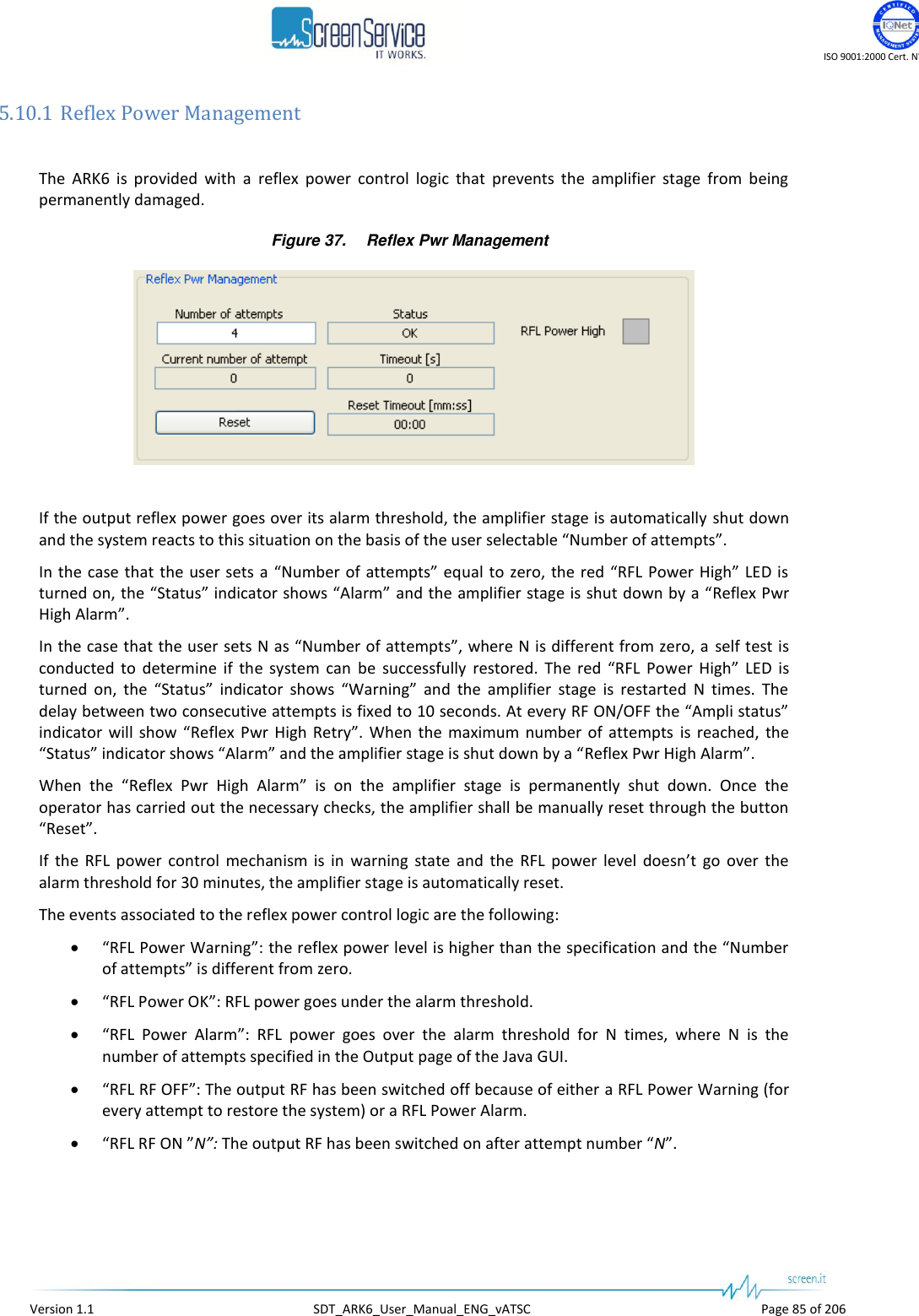
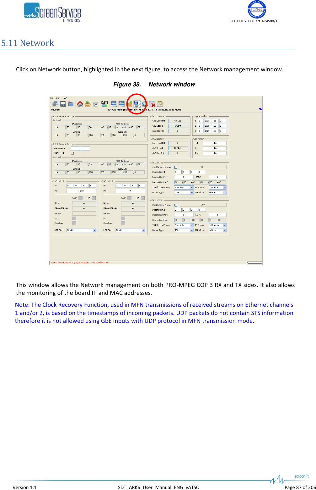
Screen Service Broadcasting Technologies SDT201UB-ARK6 125 Watt Multimode SDR Transmitter User Manual Software
Screen Service Broadcasting Technologies SpA 125 Watt Multimode SDR Transmitter Software
UserManual.wiki
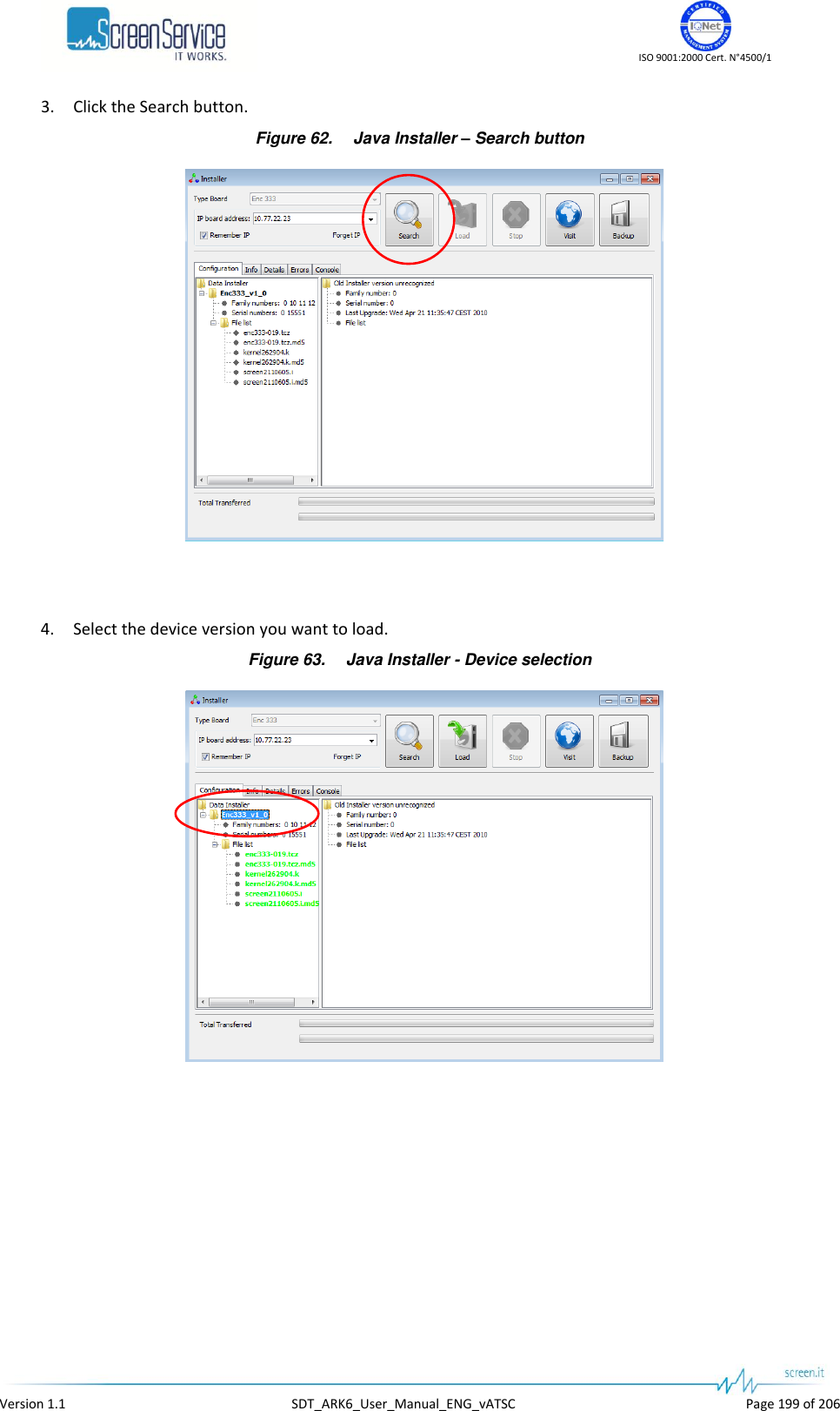
>
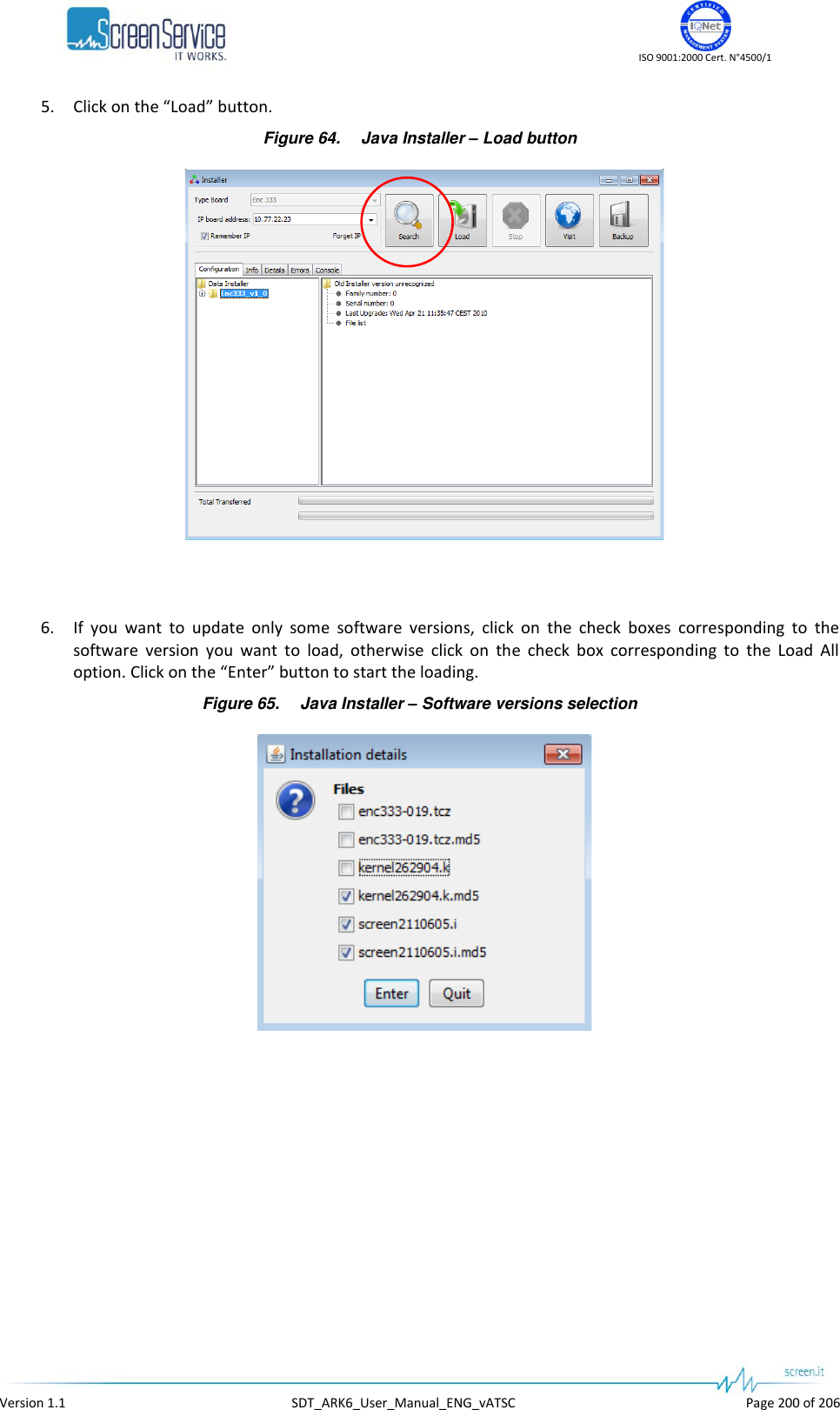
Screen Service Broadcasting Technologies
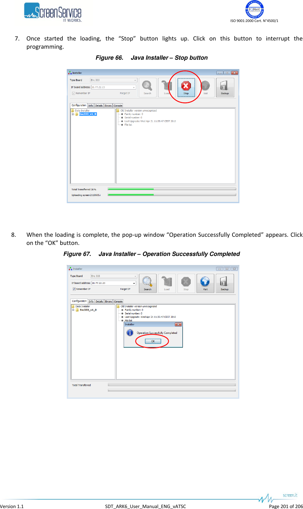
>
SDT201UB ARK6 User Manual
User Manual
Navigation menu
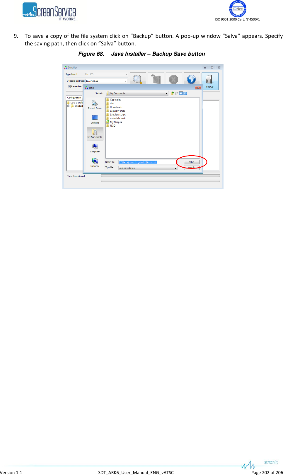
Upload a User Manual
Namespaces
Wiki Guide
HTML
PDF
Info
Views
User Manual
Discussion / Help
Navigation


![ISO 9001:2000 Cert. N°4500/1 Version 1.1 SDT_ARK6_User_Manual_ENG_vATSC Page 25 of 206 4.4 Power Supply IEC 1 Voltage 80 – 264 VAC Frequency 50 – 60 Hz ARK6 1U Mains Consumption [Test on ch. 21] MODE PWR [dBm] Vac [Volt] Iac[Amp] Consumption [W] ST-BY - 225 0,35 78,8 Power OFF - 225 0,40 90,0 Power ON 21 225 0,62 139,5 Power ON 31 225 0,64 144,0 Power ON 37 225 0,71 159,8 Power ON 41 225 0,80 180,0 ARK6 2U Mains Consumption [Test on ch. 21] MODE PWR [dBm] Vac [Volt] Iac[Amp] Consumption [W] ST-BY - 225 0,35 78,8 Power OFF - 225 0,40 90,0 Power ON 40 225 1.9 425 Power ON 47 225 2.9 650 Power ON 50 225 3.7 830 Power ON 52 225 4.4 990 Power ON 53 (1) 225 4.9 1100 Note to the table: (1) If required.](https://usermanual.wiki/Screen-Service-Broadcasting-Technologies/SDT201UB-ARK6/User-Guide-1671826-Page-25.png)
![ISO 9001:2000 Cert. N°4500/1 Version 1.1 SDT_ARK6_User_Manual_ENG_vATSC Page 26 of 206 ARK6 3U Mains Consumption [Test on ch. 45] MODE PWR [dBm] Vac [Volt] Iac[Amp] Consumption [W] ST-BY - 225 0,35 78,8 Power OFF - 225 0,40 90,0 Power ON 43 225 2.8 630 Power ON 50 225 4.5 1010 Power ON 53 225 5.7 1280 Power ON 55 225 6.8 1530 Power ON 56 (1) 225 7.4 1660 Note to the table: (1) If required.](https://usermanual.wiki/Screen-Service-Broadcasting-Technologies/SDT201UB-ARK6/User-Guide-1671826-Page-26.png)
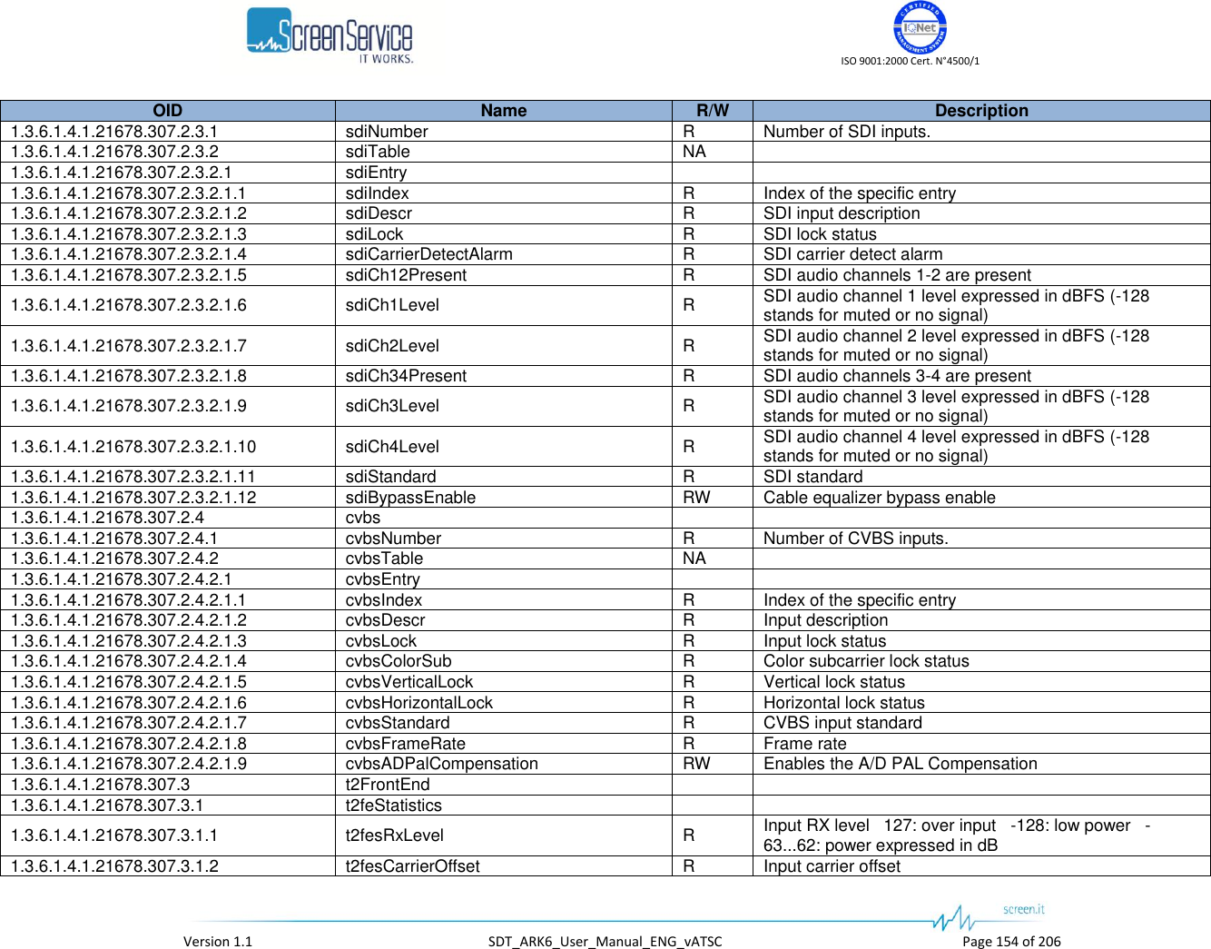
![ISO 9001:2000 Cert. N°4500/1 Version 1.1 SDT_ARK6_User_Manual_ENG_vATSC Page 35 of 206 Box Parameter / Control Description Admitted Ranges / Values GbE 2– Channel1/2 Overflow Input GbE overflow alarm status. This alarm condition occurs when the input bit-rate exceeds the capability of the modulation (Ref. to ETSI EN 302 755). Red: Alarm on Grey: Alarm off GbE 2– Statistics GBE Good Pck Total amount of frames delivered to the higher-level protocol. GbE 2– Statistics GbE Speed Ethernet connection speed. No duplex information is provided. 10 Mbit//s 100 Mbit//s 1 Gbit//s GbE 2– Statistics GBE Bad Pck The number of inbound packets that contained errors. SDI 1/2/3/4 Lock Shows the presence of a valid SDI input stream. Green: Locked Grey: Not locked SDI 1/2/3/4 CD Shows that the SDI input signal carrier has been correctly locked. Green: Locked Grey: Not locked SDI 1/2/3/4 Ch1-2 Shows that the SDI input audio data have been correctly locked. Green: Locked Grey: Not locked SDI 1/2/3/4 Ch3-4 Shows that the SDI input audio data have been correctly locked. Green: Locked Grey: Not locked SDI 1/2/3/4 Ch 1/2/3/4 Level [dBFS] Shows the embedded digital audio level. Measured in dB difference from the max digital level. 0 down to -114dB](https://usermanual.wiki/Screen-Service-Broadcasting-Technologies/SDT201UB-ARK6/User-Guide-1671826-Page-35.png)
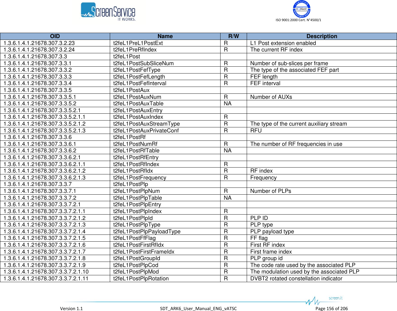
![ISO 9001:2000 Cert. N°4500/1 Version 1.1 SDT_ARK6_User_Manual_ENG_vATSC Page 36 of 206 Box Parameter / Control Description Admitted Ranges / Values SDI 1/2/3/4 Standard Shows the video standard detected for the SDI input. NTSC 4:2:2 component video; NTSC 4:2:2 16x9 component video; NTSC 4:4:4 13,5 MHz component video; PAL 4:2:2 component video; PAL 4:2:2 16x9 component video; PAL 4:4:4 13,5 MHz component video" Layers Rates Layer A/B/C Rate [bit/s] Bitrate actually used by the modulator. Used in remux mode only Layers Rates Layer A/B/C Overflow Layer input overflow alarm status. This alarm condition occurs when the input bit-rate exceeds the capability of the modulation Used in remux mode only. Red: Alarm on Grey: Alarm off Layers Rates Layer A/B/C Underflow Layer input underflow alarm status. Used in remux mode only. Red: Alarm on Grey: Alarm off](https://usermanual.wiki/Screen-Service-Broadcasting-Technologies/SDT201UB-ARK6/User-Guide-1671826-Page-36.png)
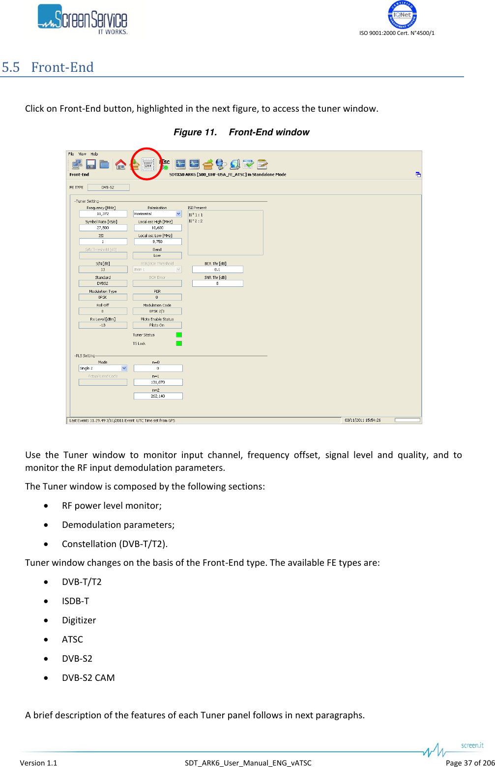
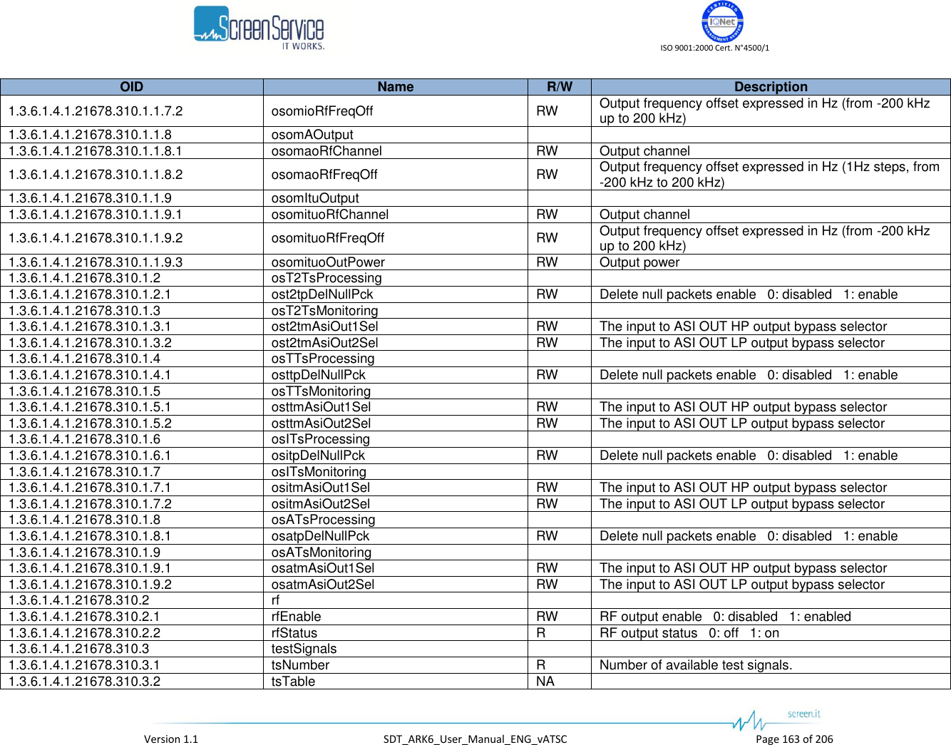
![ISO 9001:2000 Cert. N°4500/1 Version 1.1 SDT_ARK6_User_Manual_ENG_vATSC Page 38 of 206 5.5.1 Tuner window: RF power level monitor Figure 12. Tuner window: RF power level monitor Table 6. Tuner window: RF power level monitor Box Parameter / Control Description Admitted Ranges / Values General Rx Level [dBm] / Progress Bar Input RF power level monitor expressed in dBm. Min: -84 Max: -21 Low Power High Power General Low Power Rx Signal This alarm is raised when Max ADC Value is beneath the Low AGC Threshold and, consequently, both DAT 1 and DAT 2 are at their minimum values. Red: Alarm On Grey: Alarm Off General High Power Rx Signal This alarm is raised when Max ADC Value is beyond the High AGC Threshold and, consequently, both DAT 1 and DAT 2 are at their maximum values. Red: Alarm On Grey: Alarm Off General Channel This indicator shows the input RF channel. VHF: Min: E2 Max: E12 UHF: Min: 21 Max: 69 General Offset [Hz] This indicator shows the input frequency offset. Min: - 200 kHz Max: + 200 kHz General Bandwidth [MHz] Input channel bandwidth. It depends on the FE Type.](https://usermanual.wiki/Screen-Service-Broadcasting-Technologies/SDT201UB-ARK6/User-Guide-1671826-Page-38.png)
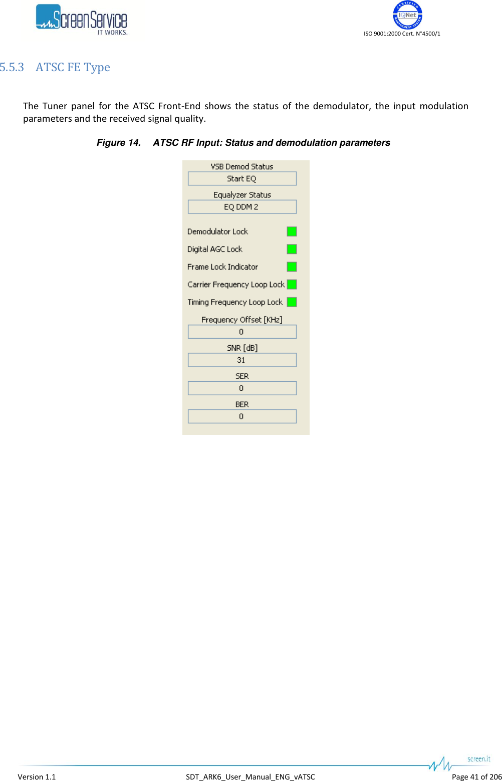
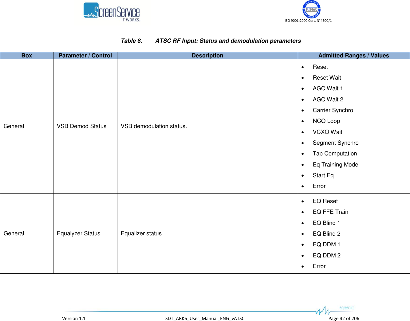
![ISO 9001:2000 Cert. N°4500/1 Version 1.1 SDT_ARK6_User_Manual_ENG_vATSC Page 43 of 206 Box Parameter / Control Description Admitted Ranges / Values General Demodulator Lock Demodulator lock status Green: Locked Grey: Unlocked General Digital AGC Lock Digital AGC lock status. Green: Locked Grey: Unlocked General Frame Lock Indicator Frame lock status. Green: Locked Grey: Unlocked General Carrier Frequency Loop Lock Carrier frequency loop lock status. Green: Locked Grey: Unlocked General Timing Frequency Loop Lock Timing frequency loop lock status. Green: Locked Grey: Unlocked General Frequency Offset [kHz] Output carrier offset. General SNR [dB] Signal to Noise Ratio [dB] General SER Segment Error Rate. General BER Bit Error Rate.](https://usermanual.wiki/Screen-Service-Broadcasting-Technologies/SDT201UB-ARK6/User-Guide-1671826-Page-43.png)
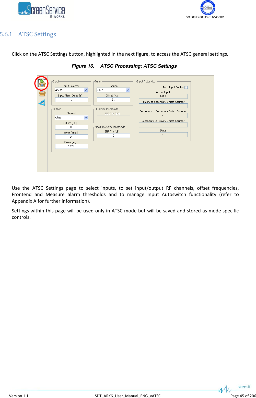
![ISO 9001:2000 Cert. N°4500/1 Version 1.1 SDT_ARK6_User_Manual_ENG_vATSC Page 46 of 206 Table 9. ATSC Processing: ATSC Settings Box Parameter / Control Description Admitted Ranges / Values Input Input Selector Input selector. It is not allowed to change input until the Input Autoswitch is enabled. In order to change the primary input, disable the Input Autoswitch functionality, select a different input through the input selector and then enable the Input Autoswitch functionality. ASI 1 ASI 2 ASI 3 ASI 4 Tuner GbE 2 ch1 GbE 2 ch2 Input Input Alarm Delay [s] Time to wait for No Input alarm rising expressed in seconds (refer to Alarms paragraph). Note: It is highly recommended to set an Input Alarm Delay value different from zero so as to allow the input signal locking. Min: 1 s Max: 25.5 s Input Autoswitch Auto Input Enable Enables the use of Input Autoswitch finite-state machine. Refer to Appendix A. for further information. Enabled Disabled Input Autoswitch Actual Input Shows the currently used input. ASI 1 ASI 2 ASI 3 ASI 4 Tuner GbE 2 ch1 GbE 2 ch2](https://usermanual.wiki/Screen-Service-Broadcasting-Technologies/SDT201UB-ARK6/User-Guide-1671826-Page-46.png)
![ISO 9001:2000 Cert. N°4500/1 Version 1.1 SDT_ARK6_User_Manual_ENG_vATSC Page 47 of 206 Box Parameter / Control Description Admitted Ranges / Values Input Autoswitch Primary to Secondary Switch Counter Primary to secondary input switch countdown expressed in seconds. Min: 0 s Max: *.def file dependant Default: 25 s Input Autoswitch Secondary to Secondary Switch Counter Secondary to secondary input switch countdown expressed in seconds. Min: 0 s Max: *.def file dependant Default: 25 s Input Autoswitch Secondary to Primary Switch Counter Secondary to primary input switch countdown expressed in seconds. Min: 0 s Max: *.def file dependant Default: 300 s Input Autoswitch State Current state of the finite-state machine Priority Input Locked Priority Input Not Locked Searching First Input Locked Check Priority Input Tuner Channel Input RF channel selector. Min: 14 Max: 77 Tuner Offset [Hz] The receiver frequency will accept offset frequencies in the range +/- 200 kHz (1 Hz steps). Min: - 200 kHz Max: + 200 kHz FE Alarm Thresholds SNR Thr [dB] FE Signal to Noise alarm threshold. Min: 10 dB Max: 50 dB](https://usermanual.wiki/Screen-Service-Broadcasting-Technologies/SDT201UB-ARK6/User-Guide-1671826-Page-47.png)
![ISO 9001:2000 Cert. N°4500/1 Version 1.1 SDT_ARK6_User_Manual_ENG_vATSC Page 48 of 206 Box Parameter / Control Description Admitted Ranges / Values MEAS Alarm Thresholds SNR Thr [dB] Meas Signal to Noise alarm threshold. Min: 10 Max: 50 Output Channel Output channel. Channel ranges are device’s definition dependant. Output Offset [Hz] Output frequency offset (expressed in Hz). Min: -200 kHz Max: +200 kHz Output Power [dBm] Output power (expressed in dBm). Output power ranges are device’s definition dependant. Output Power [W] Output power (expressed in W).](https://usermanual.wiki/Screen-Service-Broadcasting-Technologies/SDT201UB-ARK6/User-Guide-1671826-Page-48.png)
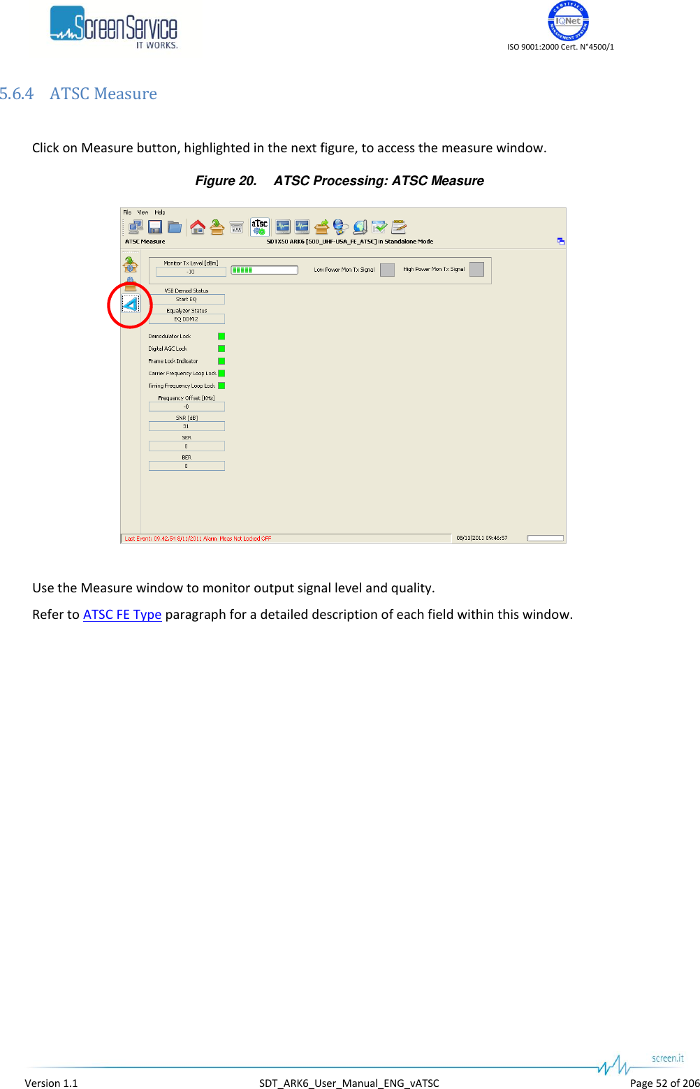
![ISO 9001:2000 Cert. N°4500/1 Version 1.1 SDT_ARK6_User_Manual_ENG_vATSC Page 53 of 206 5.6.4.1 ATSC Measure window: RF power level monitor Figure 21. ATSC Measure: RF power level monitor Table 11. ATSC Measure: RF power level monitor Box Parameter / Control Description Admitted Ranges / Values General Monitor Tx Level [dBm] / Progress Bar This value is the level of the signal, passing through the transmission section and re-entering the system after the channel filter, that will be used for the adaptive compensation. The tolerance of the read value is ±1 dB. Min: - 20 Max: 11,5 Low Power High Power General Low Power Tx Signal This alarm is raised when Max ADC Value is beneath the Low AGC Threshold and, consequently, input attenuation is at its minimum level. Red: Alarm On Grey: Alarm Off General High Power Tx Signal This alarm is raised when Max ADC Value is beyond the High AGC Threshold and, consequently, input attenuation is at its maximum level. Red: Alarm On Grey: Alarm Off](https://usermanual.wiki/Screen-Service-Broadcasting-Technologies/SDT201UB-ARK6/User-Guide-1671826-Page-53.png)
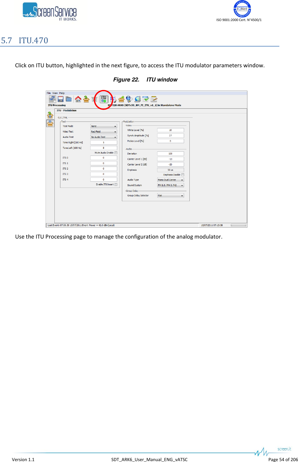
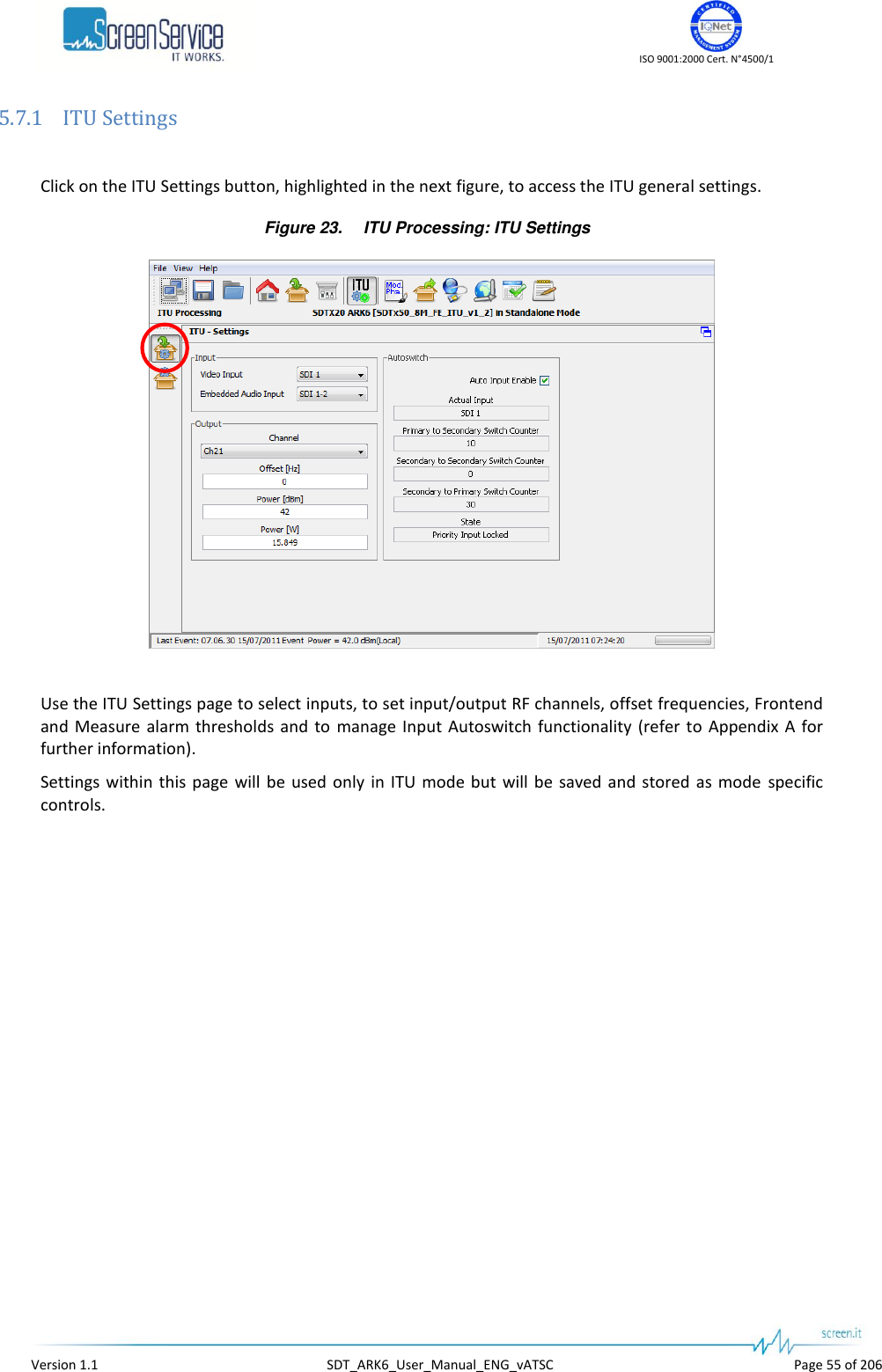
![ISO 9001:2000 Cert. N°4500/1 Version 1.1 SDT_ARK6_User_Manual_ENG_vATSC Page 56 of 206 Table 12. ITU Processing: ITU Settings Box Parameter / Control Description Admitted Ranges / Values Input Video input Video input selector. Use this control to select one of the available video inputs. CVBS analog inputs are available only when the A/V frontend is available. When and SDI input is selected, the embedded audio channel for that input are modulated and the user can select between channel 1-2 and channel 3-4. When CVBS input is selected the relative analog audio input channels are used. SDI 1 SDI 2 SDI 3 SDI 4 CVBS 1 CVBS 2 Input Embedded audio input Embedded audio channels selector. When a SDI input is selected this control can be used to send the embedded audio channels 1-2 or the embedded audio channels 3-4 to the modulation. Channel 1-2 Channel 3-4 Output Channel Output RF channel selector. Output channel selection depends on the channel planning definition loaded on the device. The following ranges and values are typical for Italian/European TV channels. VHF (BIII EU option): Min: E2 Max: E12 UHF (UHF EU option): Min: 21 Max: 69 Output Offset [Hz] The receiver frequency will accept offset frequencies in the range +/- 200 kHz (1 Hz steps). Min: - 200 kHz Max: + 200 kHz Output Power [dBm] Output power setting. This control sets the output power in dBm values. Changing this control will also change the value of power control expressed in W. Min and Max values depends on the power class of the device. e.g. for a SDTX-500 device: 28 dBm up to 48 dBm](https://usermanual.wiki/Screen-Service-Broadcasting-Technologies/SDT201UB-ARK6/User-Guide-1671826-Page-56.png)
![ISO 9001:2000 Cert. N°4500/1 Version 1.1 SDT_ARK6_User_Manual_ENG_vATSC Page 57 of 206 Box Parameter / Control Description Admitted Ranges / Values Output Power [w] Output power setting. This control sets the output power in W. Changing this control will also change the value of power control expressed in dBm. Min and Max values depends on the power class of the device. e.g. for a SDTX-500 device: 0.63 W up to 63 W Input Autoswitch Auto Input Enable Enables the use of Input Autoswitch finite-state machine. Refer to Appendix A. for further information. Enabled Disabled Input Autoswitch Actual Input Shows the currently used input. SDI 1 SDI 2 SDI 3 SDI 4 CVBS 1 CVBS 2 Input Autoswitch Primary to Secondary Switch Counter Primary to secondary input switch countdown expressed in seconds. Min: 0 s Max: *.def file dependant Default: 25 s Input Autoswitch Secondary to Secondary Switch Counter Secondary to secondary input switch countdown expressed in seconds. Min: 0 s Max: *.def file dependant Default: 25 s Input Autoswitch Secondary to Primary Switch Counter Secondary to primary input switch countdown expressed in seconds. Min: 0 s Max: *.def file dependant Default: 300 s](https://usermanual.wiki/Screen-Service-Broadcasting-Technologies/SDT201UB-ARK6/User-Guide-1671826-Page-57.png)
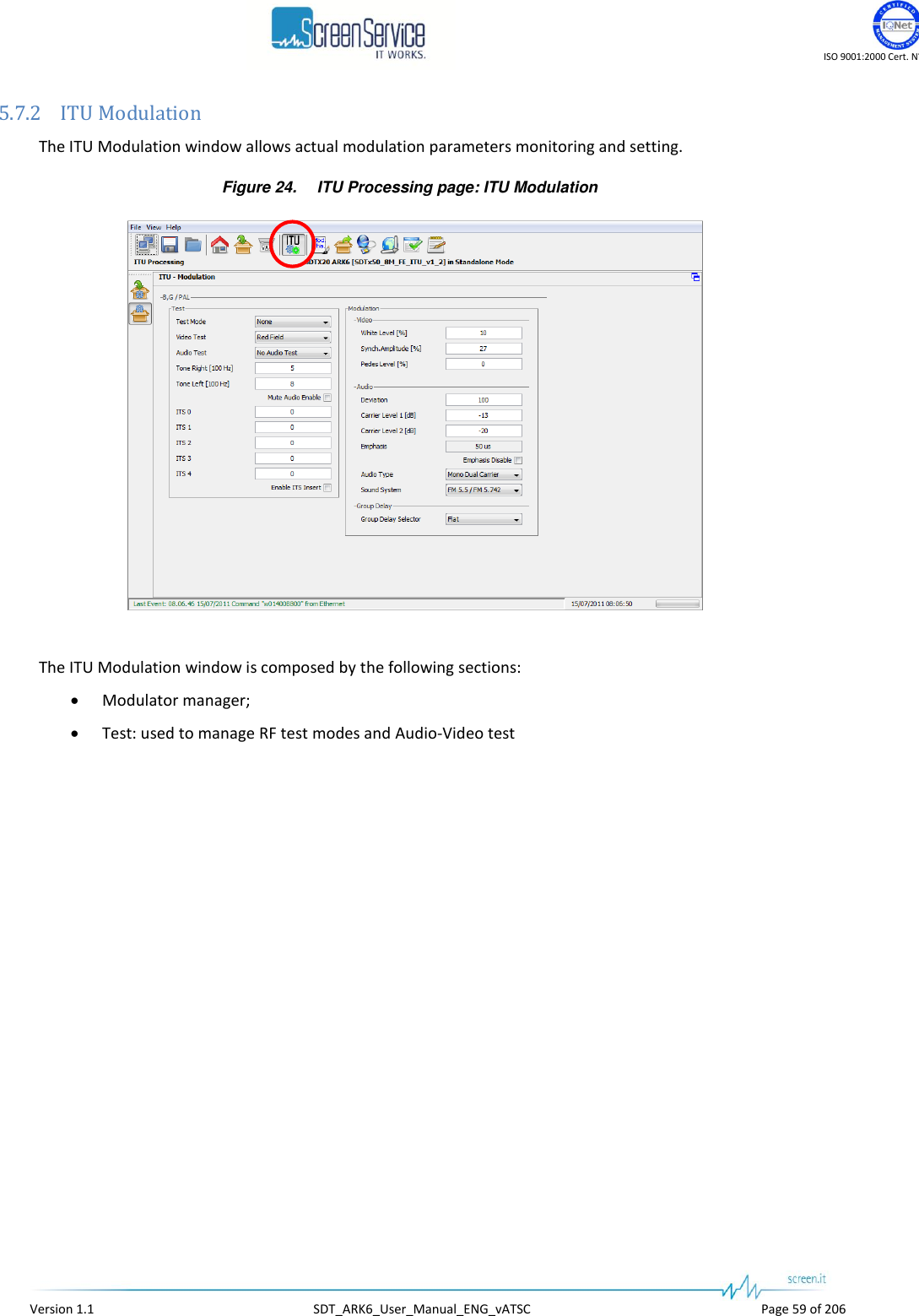
![ISO 9001:2000 Cert. N°4500/1 Version 1.1 SDT_ARK6_User_Manual_ENG_vATSC Page 61 of 206 Table 13. ITU Modulation: Modulator manager Box Parameter / Control Description Admitted Ranges / Values Video White Level [%] Video white level setting. The level value is in percentage upon the synch level. The synch level is taken as 100% reference. MIN: 10 MAX: 22 Step: 0,05 Video Synch. Amplitude [%] Video synch amplitude setting. The level value is in percentage upon the synch level. The synch level is taken as 100% reference. MIN: 22 MAX: 27,5 Step: 0,05 Video Pedes Level [%] Video pedes level setting. The level value is in percentage upon the synch level. The synch level is taken as 100% reference. MIN: 0 MAX: 7 Step: 0,05 Audio Deviation Audio deviation. This parameter is used to change the frequency deviation of the audio modulation in order to adjust the audio volume. Relative values 0 up to 255 Default value 100 Audio Carrier Level 1 [dB] Audio 1 carrier level setting. This parameter is the amplitude difference, expressed in dB values, between the video carrier and the audio 1 carrier. MIN: -22 MAX: -7 Step: 1](https://usermanual.wiki/Screen-Service-Broadcasting-Technologies/SDT201UB-ARK6/User-Guide-1671826-Page-61.png)
![ISO 9001:2000 Cert. N°4500/1 Version 1.1 SDT_ARK6_User_Manual_ENG_vATSC Page 62 of 206 Box Parameter / Control Description Admitted Ranges / Values Audio Carrier Level 2 [dB] Audio 2 carrier level setting. This parameter is the amplitude difference, expressed in dB values, between the video carrier and the audio 1 carrier. Not used for mono audio carrier configurations such as NTSC or PAL M. MIN: -22 MAX: -7 Step: 1 Audio Emphasis Audio emphasis value monitor. The audio emphasis used depends on the modulation standard. 50us (used for PAL-BG) 75us Audio Emphasis disable Audio emphasis disable. This control disables the audio emphasis. Audio emphasis enabled (not ticked); Audio emphasis disabled (ticked). Audio Audio type Audio modulation type selection. This control selects the audio modulation mode. Stereo and dual carrier modes are not available for standards that support mono audio only. Mono dual carrier; Dual sound; Stereo; Mono single carrier. Audio Sound system Audio carrier spacing selector. This control shows more options for the standard that supports more than one audio carrier spacing. FM 5.5/5.742 Group delay Group delay selector Select the group delay to apply. The available group delay curve depends on the group delay definition loaded on the device. e.g. for PAL BG: Flat (no group delay curve) Curve A Curve B](https://usermanual.wiki/Screen-Service-Broadcasting-Technologies/SDT201UB-ARK6/User-Guide-1671826-Page-62.png)
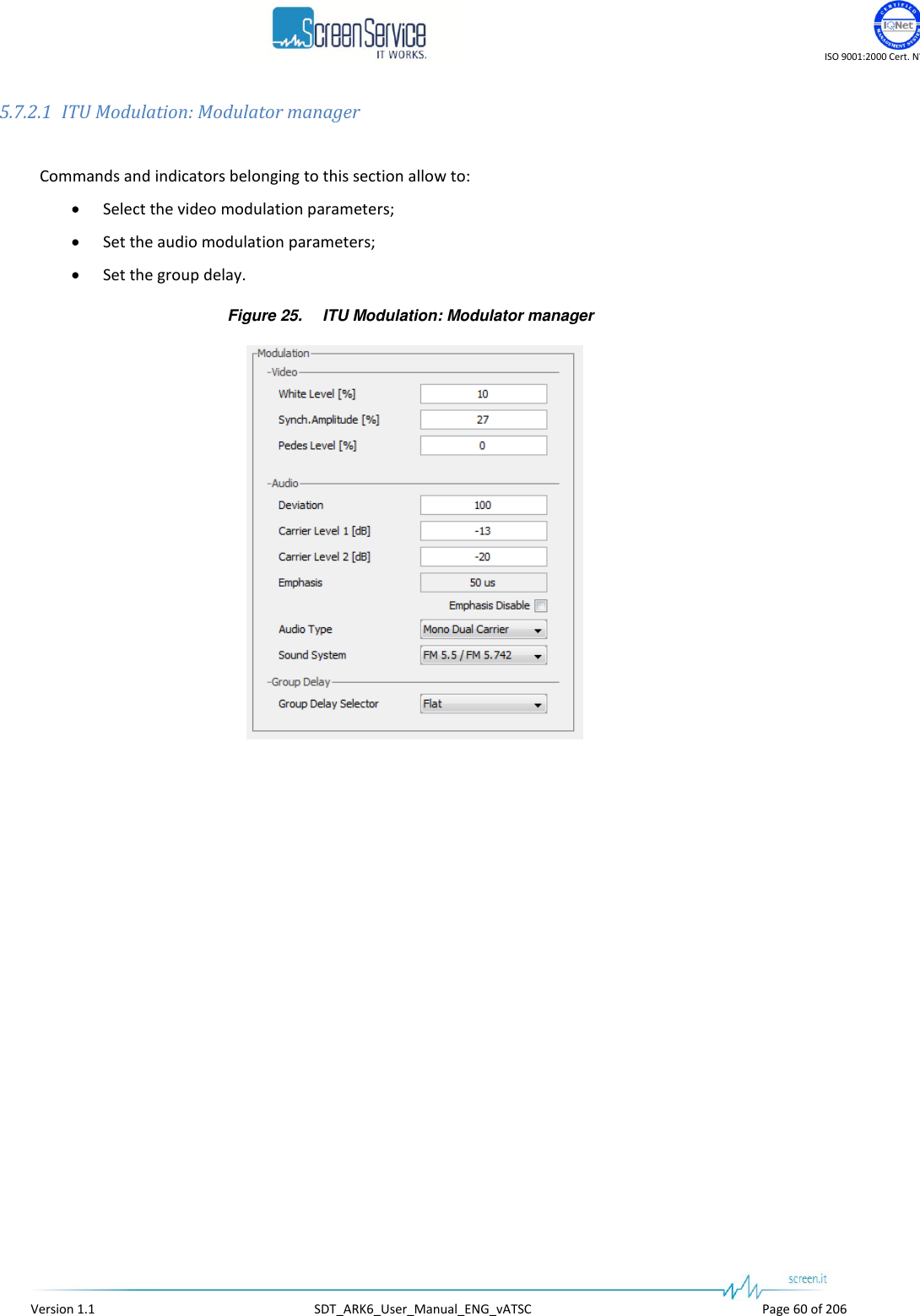
![ISO 9001:2000 Cert. N°4500/1 Version 1.1 SDT_ARK6_User_Manual_ENG_vATSC Page 64 of 206 Table 14. ITU Modulation: Modulator test modes Box Parameter / Control Description Admitted Ranges / Values Test Test mode Enables one of the available test modes for RF signal. None; CW: non modulated carrier at centre frequency; CW AV: non modulated video and audio carriers; Test Video test Enables one of the available video test signals. Input video. No test signal; SMPTE bars; Horizontal bars; Red field. Test Audio test Enables one of the available audio test signals. No audio test; Test tone. Sin waves at the selected frequency on left and right channel. (Left only for mono modulations) Test Tone right [100 Hz] Set the frequency of the right channel test tone. Base unit is 100Hz. Base unit 100 Hz; 0 up to 127, 0 up to 12.7 kHz. Test Tone left [100 Hz] Set the frequency of the right channel test tone. Base unit is 100Hz. Base unit 100 Hz; 0 up to 127, 0 up to 12.7 kHz. Test Mute audio enable Enables the audio carriers’ suppression for test purposes. Mute audio disabled: audio carries are transmitted; Mute audio enabled: audio carriers are suppressed.](https://usermanual.wiki/Screen-Service-Broadcasting-Technologies/SDT201UB-ARK6/User-Guide-1671826-Page-64.png)
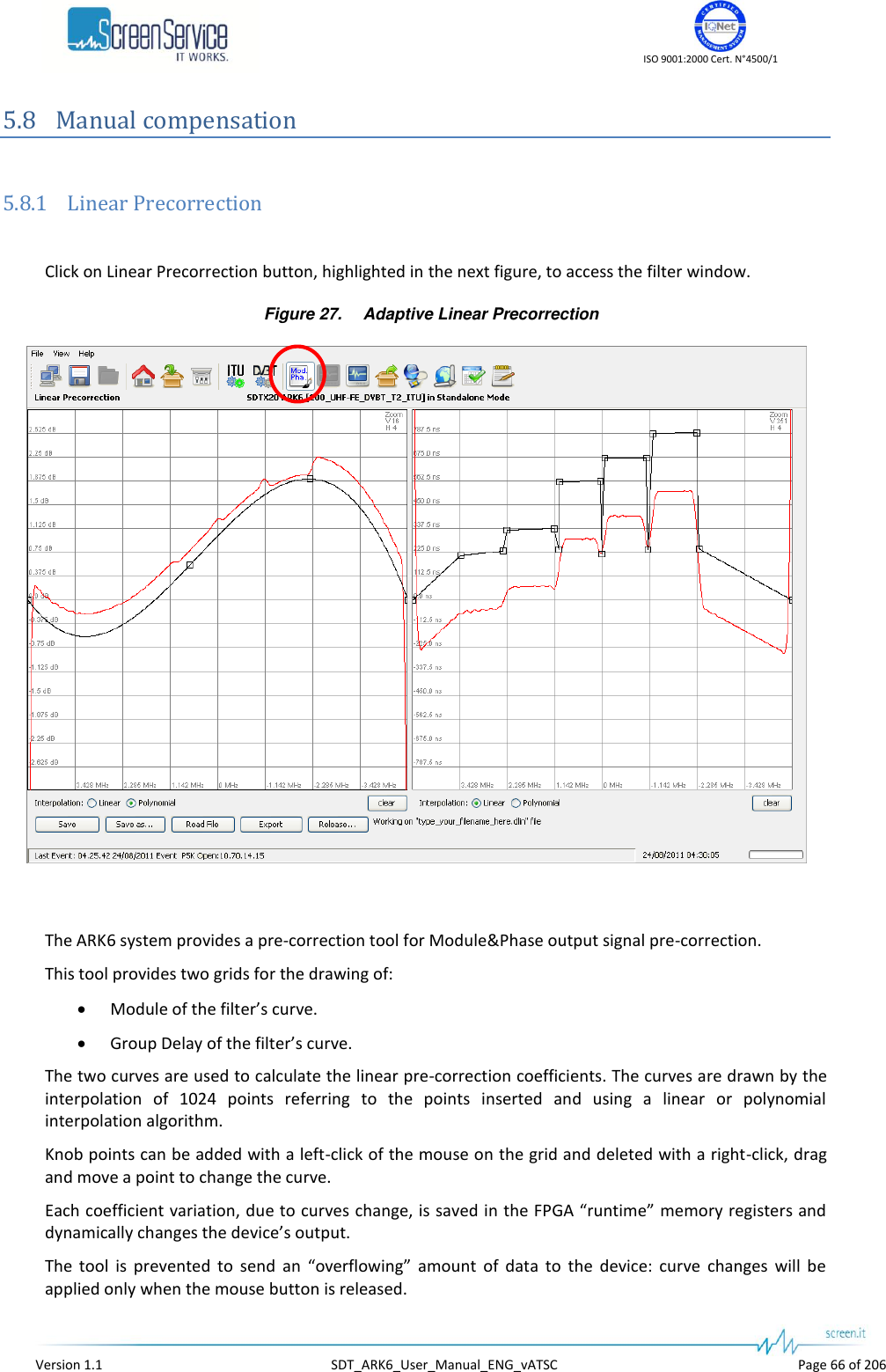
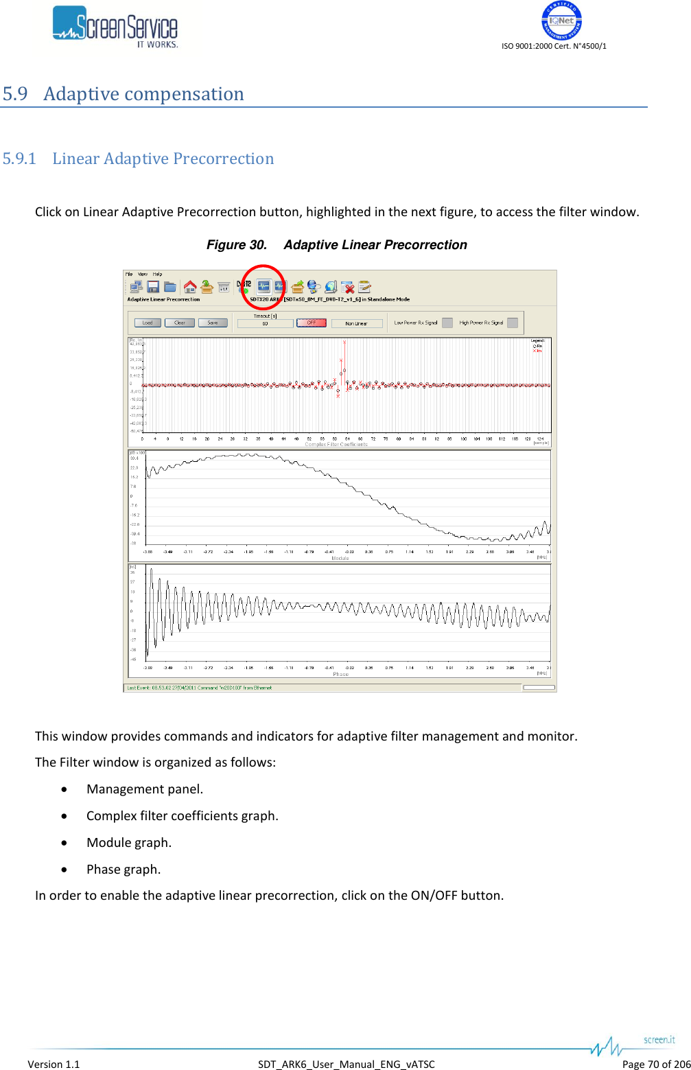
![ISO 9001:2000 Cert. N°4500/1 Version 1.1 SDT_ARK6_User_Manual_ENG_vATSC Page 72 of 206 5.9.1.2 Adaptive Linear Precorrection: Management panel Table 15. Adaptive Linear Precorrection: Management panel Box Parameter / Control Description Admitted Ranges / Values General Load Loads filter coefficients from the respective FPGA registers. General Clear Loads flat curve coefficients. General Timeout [s] Once enabled, the adaptive linear compensation has a timeout. When the timeout is expired, the precorrection is stopped. In order to continue updating coefficients, click on ON/OFF button. Fixed to 60 seconds General Save Saves the current adaptive filter coefficients. General ON/OFF Enables the adaptive linear compensation. ON(Green):Enabled OFF(Red): Disabled General Status Shows the type of adaptive compensation currently used, if any. None Linear Non Linear General Low Power Rx Signal Indicates that the signal that re-enters the system has a low power. When this flag is on, the automatic update of the filter coefficients is stopped. Red: Alarm On Grey: Alarm Off General High Power Rx Signal Indicates that the signal that re-enters the system has a high power. When this flag is on, the automatic update of the filter coefficients is stopped. Red: Alarm On Grey: Alarm Off](https://usermanual.wiki/Screen-Service-Broadcasting-Technologies/SDT201UB-ARK6/User-Guide-1671826-Page-72.png)
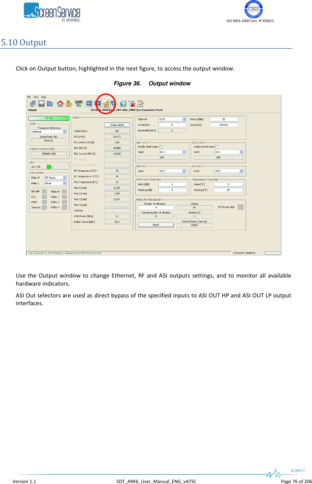
![ISO 9001:2000 Cert. N°4500/1 Version 1.1 SDT_ARK6_User_Manual_ENG_vATSC Page 77 of 206 Table 17. Output window Box Parameter / Control Description Admitted Ranges / Values General RF ON / OFF Output RF signal enabling. The possible output RF signal status are the following: ON; RF OFF: automatic switch off of the output signal (refer to Amplifier status); OFF: manual switch off of the output signal. Green: ON Green: RF OFF Red: OFF Clock Frequency reference Frequency reference source selector. This command will select the reference source used to lock the internal clocks (10 MHz and 1 PPS). When set to internal the 10 MHz clock and 1 PPS generator runs unlocked. When set to external or GPS the 10 MHz clock is locked to the source selected and the 1 PPS counter reset is triggered by the source 1 PPS. Note: External 10 MHz, 1PPS and GPS shall be connected and locked when the External and GPS are selected as frequency references. If the Network Mode is SFN and the Frequency Reference is set to Internal, the frequency reference is automatically forced to GPS and the event “Freq Ref Forced: GPS” is generated Use the Actual Freq. Ref.indicator in order to check the used reference source. External Internal GPS Clock Actual Freq. Ref. Frequency reference source actually used. External Internal GPS Centre Frequency[Hz] Shows the output centre frequency expressed in Hz. AGC AGC ON AGC status. Green: ON Grey: OFF](https://usermanual.wiki/Screen-Service-Broadcasting-Technologies/SDT201UB-ARK6/User-Guide-1671826-Page-77.png)
![ISO 9001:2000 Cert. N°4500/1 Version 1.1 SDT_ARK6_User_Manual_ENG_vATSC Page 78 of 206 Box Parameter / Control Description Admitted Ranges / Values Status PS 26V [V] First PSU voltage indicator, expressed in Volt, for SDTx20, SDTx50, SDTx201 and SDTx501 devices. Min: 24V Max: 28V Status PS Current 26V [A] First PSU current indicator, expressed in Ampere, for SDTx20, SDTx50, SDTx201 and SDTx501 devices. Max: 8A Status PS1 50V [V] Second PSU voltage indicator, expressed in Volt, for SDTx201 and SDT501 devices. Min: 45V Max: 55V Status PS1 Current 50V [A] Second PSU current indicator, expressed in Ampere, for SDTx201 and SDT501 devices. Max: 18A Status PS2 50V [V] Third PSU voltage indicator, expressed in Volt, for SDTx501 devices. Min: 45V Max: 55V Status PS2 Current 50V [A] Third PSU current indicator, expressed in Ampere, for SDTx501 devices. Max: 18A Status Ampli status Current amplifier status indicator: 1. ON: the amplifier has been manually set to on and no alarms or settings switched it off 2. PS Alarm OFF: when an alarm of over current, over voltage or over power occurs on the second or third Power Supply, the Amplifier is restarted four times, if the alarm is still on, the Amplifier is automatically switched off. Single Power Supply models do not support this status 3. Restart: the amplifier has been automatically restarted due to an alarm for over current, over voltage or forward power exceeding the upper limit on the second Power Supply. Single Power Supply models do not support this status 4. Stand-by OFF: the equipment has been put on Standby mode and the amplifier has been automatically muted 5. Init: at every amplifier initialization the amp is automatically switched off. ON PS Alarm OFF Restarting Stand-by OFF Init Alarm OFF RF OFF Opto OFF Change mode Missing file OFF](https://usermanual.wiki/Screen-Service-Broadcasting-Technologies/SDT201UB-ARK6/User-Guide-1671826-Page-78.png)
![ISO 9001:2000 Cert. N°4500/1 Version 1.1 SDT_ARK6_User_Manual_ENG_vATSC Page 79 of 206 Box Parameter / Control Description Admitted Ranges / Values 6. Alarm OFF: an alarm switched off the amplifier 7. RF OFF: amplifier manually set to off 8. Opto OFF: output RF is switched off by an optocoupler 9. Change mode: the amplifier is automatically switched off during the mode switch (e.g. T1 / T2) 10. Missing file OFF: the amplifier is automatically switched off because of the lack of *.cdef and *.def files (additional files will be included in future releases). 11. Loading New Config: the amplifier is automatically switched off during the loading of new T2 configuration parameters, 12. Reflex Pwr High retry: the output RF stage has been restart because of the reflex power that has gone over the maximum threshold. 13. Reflex Pwr Alarm: the maximum number of attempts to restore the system after a Reflex Power High warning has been reached, the equipment is in Reflex Power High alarm and the Amplifier has been automatically switched off. 14. Test Mode: the amplifier is in ON state, but the transmitter is modulating a test signal instead of the selected input. 15. Start New Firmware: during the loading of a new fw the output RF is OFF. 16. Restart Mode: a system error occurs and the FPGA fw boot is forced. During these operations the amplifier is turned OFF. Loading New Config Reflex Pwr High Retry Reflex Pwr High Alarm Test Mode Start New Fw Restart Mode Status RF Temperature [°C] Case temperature indicator (values are expressed in °C). Status RF Temperature 2 [°C] 2nd Case temperature indicator (values are expressed in °C). Only in SDTx201 and SDTx501 versions. Status PSU Temperature PSU temperature indicator (values are expressed in °C). Status Fan 1 Fan 1 speed indicator (values are expressed in rpm). Used in SDTx20, SDTx50, SDTx201 and SDTx501](https://usermanual.wiki/Screen-Service-Broadcasting-Technologies/SDT201UB-ARK6/User-Guide-1671826-Page-79.png)
![ISO 9001:2000 Cert. N°4500/1 Version 1.1 SDT_ARK6_User_Manual_ENG_vATSC Page 80 of 206 Box Parameter / Control Description Admitted Ranges / Values Status Fan 2 Fan 2 speed indicator (values are expressed in rpm). Used in SDTx20, SDTx50, SDTx201 and SDTx501. Status Fan 3 Fan 3 speed indicator (values are expressed in rpm). Used in SDTx20, SDTx50, SDTx201 and SDTx501. Status Fan 4 Fan 4 speed indicator (values are expressed in rpm). Used in SDTx501. Status CPU Fan Shows the status of the CPU fan. There are two types of errors: Fan fault: fan speed equal to zero; No Fan: the CPU fan is not connected. FAN_OK FAN_FAULT NO_FAN Status FWD Power [dBm] Output forward power indicator (values are expressed in dBm). Status Reflex Power [dBm] Output reflex power indicator (values are expressed in dBm). Opto & Relay Relay 0 Selector of Relay 0 mode. Alarm: indicator of an alarm condition Mode: indicator of operating mode RF Status: indicator output RF signal status (on/off) Opto & Relay Relay 1 Selector of Relay 1 mode. Alarm: indicator of an alarm condition Mode: indicator of operating mode](https://usermanual.wiki/Screen-Service-Broadcasting-Technologies/SDT201UB-ARK6/User-Guide-1671826-Page-80.png)
![ISO 9001:2000 Cert. N°4500/1 Version 1.1 SDT_ARK6_User_Manual_ENG_vATSC Page 82 of 206 Box Parameter / Control Description Admitted Ranges / Values General Offset [Hz] Output frequency offset (expressed in Hz). Min: -200 kHz Max: +200 kHz General Power [dBm] Output power (expressed in dBm). Output power ranges are device’s definition dependant. General Power [W] Output power (expressed in W). General Bandwidth [MHz] The output channel bandwidth. It depends on the device definition. FWD Power Thresholds Warning [dB] Forward power warning threshold expressed in dB. Min: -16 dB Max: 0 dB FWD Power Thresholds Alarm [dB] Forward power alarm threshold expressed in dB. Temperature Thresholds Warning [°C] Temperature warning threshold expressed in °C. Min: 50 °C Max: 74 °C Temperature Thresholds Alarm [°C] Temperature alarm threshold expressed in °C. GbE 2 ch1/2 Tx Enable send frame Ethernet channel 1 transmission enabling. Checked: Enabled Not checked: Disabled](https://usermanual.wiki/Screen-Service-Broadcasting-Technologies/SDT201UB-ARK6/User-Guide-1671826-Page-82.png)

![ISO 9001:2000 Cert. N°4500/1 Version 1.1 SDT_ARK6_User_Manual_ENG_vATSC Page 86 of 206 Table 18. Output window: Reflex Pwr Management Box Parameter / Control Description Admitted Ranges / Values Reflex Pwr Management Number of attempts The number of attempts to restore the system after RFL power has gone over the alarm threshold. Min: 0 Max: 255 Reflex Pwr Management Current number of attempt The current number attempt to restore the system. Min: 0 Max: “Number of attempts” Reflex Pwr Management Status It shows the current status of the Reflex Power. OK Warning Alarm Reflex Pwr Management RFL Power High It shows if RFL power goes over the alarm threshold. Red: RFL power over the alarm threshold Grey: RFL power under the alarm threshold Reflex Pwr Management Timeout [s] The timeout between two consecutive attempts. Fixed to 10 seconds Reflex Pwr Management Reset This button resets the amplifier stage when it is switched off due to a Reflex Power High alarm. Reflex Pwr Management Reset Timeout [s] If the RFL power control mechanism is in warning state and the RFL power level doesn’t go over the alarm threshold for 30 minutes, the amplifier stage is automatically reset. Fixed to 30 minutes](https://usermanual.wiki/Screen-Service-Broadcasting-Technologies/SDT201UB-ARK6/User-Guide-1671826-Page-86.png)
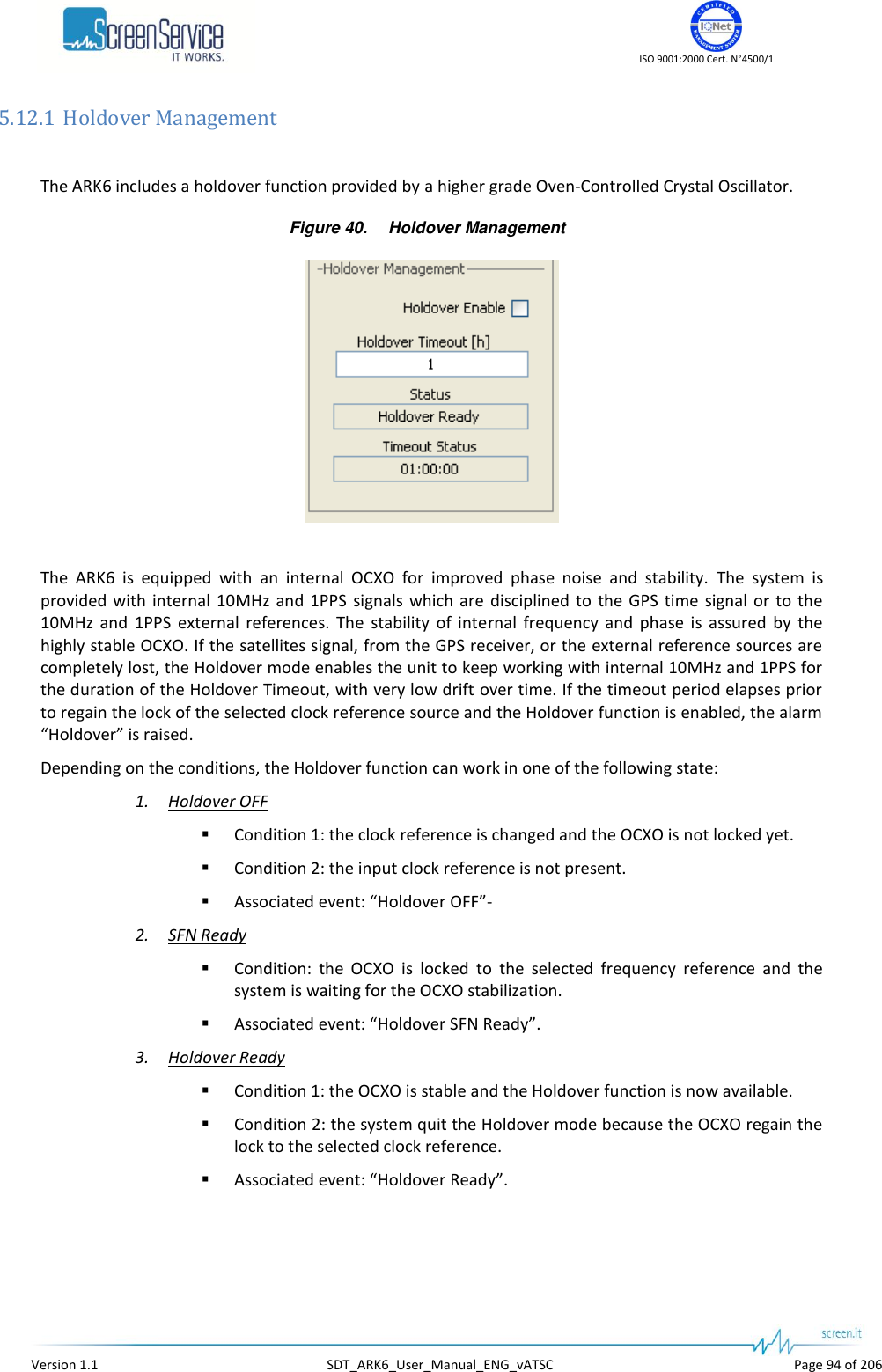
![ISO 9001:2000 Cert. N°4500/1 Version 1.1 SDT_ARK6_User_Manual_ENG_vATSC Page 97 of 206 Box Parameter / Control Description Admitted Ranges / Values OCXO GPS Lock OCXO locked to the external GPS reference. Green: Locked Grey: Not Locked OCXO Tracking It shows whenever the OCXO is not locked to the selected frequency reference or not. Green: Locked Grey: Not Locked OCXO SFN Ready It shows whenever the OCXO is locked to the selected frequency reference and the system is waiting for the OCXO stabilization or not. Green: SFN Ready Grey: SFN Not Ready OCXO Holdover Ready It shows whenever the Holdover function is available or not. Green: Holdover Ready Grey: Holdover Not Ready OCXO Holdover It notifies that the equipment entered into Holdover mode Green: Holdover On Grey: Holdover Off Holdover Management Holdover Enable Enables the Holdover mechanism. Checked: Enabled Not checked: Disabled Holdover Management Holdover Timeout [h] Sets the timeout of the Holdover in hour. Min: 0 h Max: 24 h Holdover Management Status The status of the Holdover mechanism. OFF SFN Ready Ready ON Expired](https://usermanual.wiki/Screen-Service-Broadcasting-Technologies/SDT201UB-ARK6/User-Guide-1671826-Page-97.png)
![ISO 9001:2000 Cert. N°4500/1 Version 1.1 SDT_ARK6_User_Manual_ENG_vATSC Page 98 of 206 Box Parameter / Control Description Admitted Ranges / Values Holdover Management Timeout Status The countdown of the Holdover timeout. Min:00:00:00 Max: “Holdover Timeout [s]”](https://usermanual.wiki/Screen-Service-Broadcasting-Technologies/SDT201UB-ARK6/User-Guide-1671826-Page-98.png)
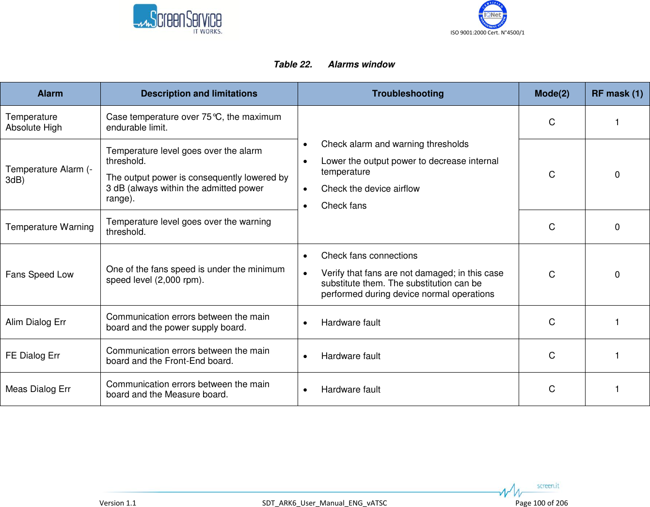
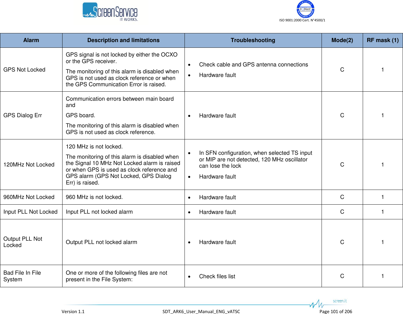
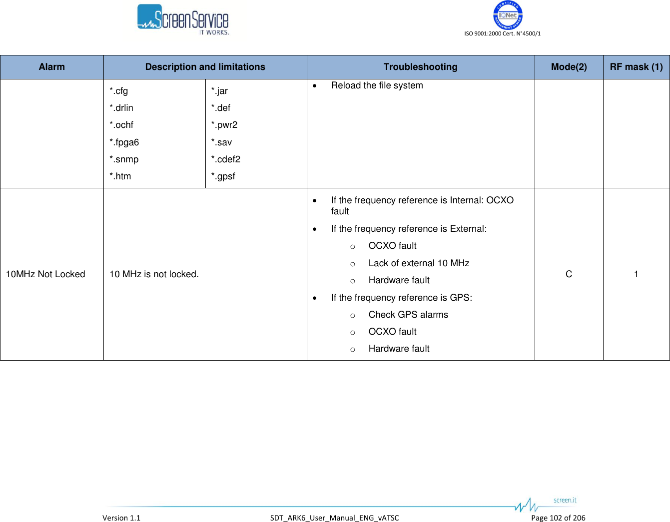
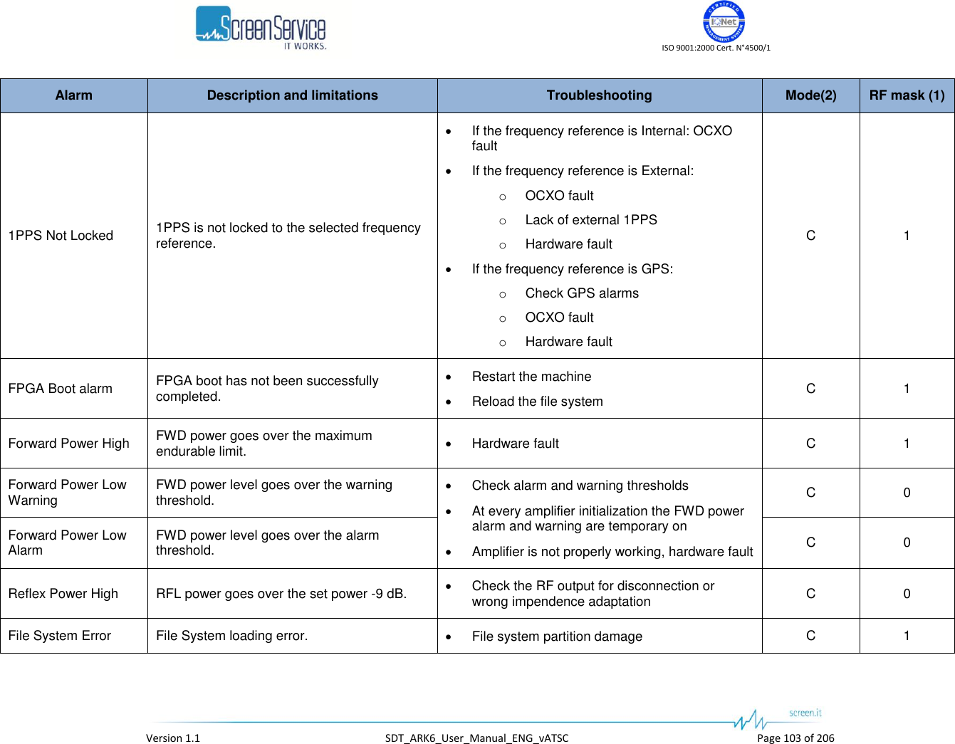
![ISO 9001:2000 Cert. N°4500/1 Version 1.1 SDT_ARK6_User_Manual_ENG_vATSC Page 104 of 206 Alarm Description and limitations Troubleshooting Mode(2) RF mask (1) PS Voltage Out Of Range Power Supply voltage out of range. This alarm is risen when at least one of the following conditions is met: PS 26V < 24V or > 28V PS1/PS2 50V < 45V or > 55V Hardware fault C 1 PS Current Out Of Range Power Supply current out of range. This alarm is risen when at least one of the following conditions is met: PS Current 26V > 8A PS1/PS2 Current 50V> 18A Hardware fault C 1 CPU Fan Error CPU fan speed equal to zero or CPU fan not connected. Check fan connection C 1 Test Mode The equipment is generating a test signal. Disable the test signal C 0 FE S2 Not Locked Lock state indicator of the satellite feed. Check input signal and cable C X FE S2 S/N Low Front-End S/N measure goes over the alarm threshold. Check input signal and cable C X FE S2 BER High Front-End BER measure goes over the alarm threshold. Check input signal and cable C X FE S2 Global Alarm C X [DVB-T2] No Input Selected TS input not locked. Check input cable Check input statistics T2 X](https://usermanual.wiki/Screen-Service-Broadcasting-Technologies/SDT201UB-ARK6/User-Guide-1671826-Page-104.png)
![ISO 9001:2000 Cert. N°4500/1 Version 1.1 SDT_ARK6_User_Manual_ENG_vATSC Page 105 of 206 Alarm Description and limitations Troubleshooting Mode(2) RF mask (1) [DVB-T2] Input Overflow Selected TS input overflow. Check the capability of the current modulation scheme Check if the configuration has been loaded T2 X [DVB-T2] FE Not Locked Logical AND between FE TS lock and FE demodulator ready (SyncStat equals to 6). Check input signal and cable T2 X [DVB-T2] FE Squelch Front-End Squelch level goes over the alarm threshold. Check input signal and cable T2 X [DVB-T2] FE Pre LDPC BER High Front-End Pre LDPC BER goes over the alarm threshold. Check input signal and cable T2 X [DVB-T2] FE SNR Low Front-End SNR goes under the alarm threshold. Check input signal and cable T2 X [DVB-T2] FE MER Low Front-End MER goes under the alarm threshold. Check input signal and cable T2 X [DVB-T2] FE Signal Quality Low Front-End Signal Quality goes under the alarm threshold. Check input signal and cable T2 X [DVB-T2] MEAS Not Locked Logical AND between Meas TS lock and Meas demodulator ready (SyncStat equals to 6). Check the configuration Check if the configuration has been loaded T2 0 [DVB-T2] MEAS Pre LDPC BER High Measure Pre LDPC BER goes over the alarm threshold. Check the configuration Check if the configuration has been loaded T2 0 [DVB-T2] MEAS SNR Low Measure SNR goes under the alarm threshold. Check the configuration Check if the configuration has been loaded T2 0](https://usermanual.wiki/Screen-Service-Broadcasting-Technologies/SDT201UB-ARK6/User-Guide-1671826-Page-105.png)
![ISO 9001:2000 Cert. N°4500/1 Version 1.1 SDT_ARK6_User_Manual_ENG_vATSC Page 106 of 206 Alarm Description and limitations Troubleshooting Mode(2) RF mask (1) [DVB-T2] MEAS MER Low Measure MER goes under the alarm threshold. Check the configuration Check if the configuration has been loaded T2 0 [DVB-T2] MEAS Signal Quality Low Measure Signal Quality goes under the alarm threshold. Check the configuration Check if the configuration has been loaded T2 0 [DVB-T2] T2-MI Err The logical OR of the following conditions: CRC of incoming T2-MI pkts is not correct. The Network mode is SFN but the selected Parameters Source is not T2-MI Parameters. Check input signal T2 1 [DVB-T2] T2-MIP Err T2-MIP errors Check input signal T2 X [DVB-T2] Holdover An alarm that is raised when the Holdover function is enabled and the set timeout period elapsed prior to regain the lock of the frequency reference. Check input frequency reference source. T2 X [DVB-T2] PPS Phase 1PPS is not lock to a source reference common to the network. This alarm is available only when the frequency reference is external. Check 1PPS Hardware fault T2 X [DVB-T2] Configuration Not Loaded Some configuration parameters have been changed and the current configuration has not been loaded yet. Load the configuration through the Load Config button in DVB-T2 Processing window T2 X [DVB-T2] FE LDPC Mean Err RF input LDPC iteration per minute goes over the alarm threshold. Check input signal T2 X](https://usermanual.wiki/Screen-Service-Broadcasting-Technologies/SDT201UB-ARK6/User-Guide-1671826-Page-106.png)
![ISO 9001:2000 Cert. N°4500/1 Version 1.1 SDT_ARK6_User_Manual_ENG_vATSC Page 107 of 206 Alarm Description and limitations Troubleshooting Mode(2) RF mask (1) [DVB-T2] MEAS LDPC Mean Err RF output LDPC iteration per minute goes over the alarm threshold. Check input signal T2 0 [DVB-T2] SFN Alarm The logical OR of the following conditions: T2-MI Timestamp error. T2-MI Timestamp wrong CRC. T2-MI Timestamp not present. The Holdover status is either OFF or TMO Expired. The monitoring of this alarm is disabled when the [DVB-T2] T2-MI Err alarm is on and when the Network mode is MFN. Check input signal T2 X [DVB-T] Input Not present Alarm Seamless improper working warning One or both Seamless logic input of the current mode isn’t locked. This alarm is enable only in Tx DVBT mode Check connection status of physical input associated to logic input Check type and source of input associated to logic input Hardware fault T 0](https://usermanual.wiki/Screen-Service-Broadcasting-Technologies/SDT201UB-ARK6/User-Guide-1671826-Page-107.png)
![ISO 9001:2000 Cert. N°4500/1 Version 1.1 SDT_ARK6_User_Manual_ENG_vATSC Page 108 of 206 Alarm Description and limitations Troubleshooting Mode(2) RF mask (1) [DVB-T] Input Not valid Alarm Seamless improper working warning An error has been detected on Logical seamless input. The possible errors which may be detected on input are: PAT error MIP error TS synchronization Packet jitter Transport error ASI word error When the alarm is detected, an event (if event mask is enabled on alarm mask) shows the cause of the error. The cause shown is only one, and it is the heaviest one. The priority in the errors is as previously listed (the heaviest error cause is the one listed in the bottom of the list, and so on). Check input signal Check cable connection status Hardware fault T 0 [DVB-T] MIP Delay High Seamless improper working warning This alarm is high when the MIP in one of the seamless inputs of the current mode, is not in its expected position. This can be caused by a too high delay on the input. Check cable connections Check Network delay Hardware Fault T 0 [DVB-T] No Input Selected TS input not locked. It could be either ASI or Tuner input. Check input cable Check input statistics T X [DVB-T] Input Overflow Selected TS input overflow. Check the capability of the current modulation scheme T X](https://usermanual.wiki/Screen-Service-Broadcasting-Technologies/SDT201UB-ARK6/User-Guide-1671826-Page-108.png)
![ISO 9001:2000 Cert. N°4500/1 Version 1.1 SDT_ARK6_User_Manual_ENG_vATSC Page 109 of 206 Alarm Description and limitations Troubleshooting Mode(2) RF mask (1) [DVB-T] MIP Err MIP packets missing. This alarm’s RF OFF mask should always be enabled. Alarm raising limitations: The monitoring of this alarm is enabled only when the device has SFN modulation enabled. The monitoring of this alarm is disabled when a No Input alarm is raised. Check input signal T 1 [DVB-T] PPS Phase 1PPS is not lock to a source reference common to the network. This alarm is available only when the frequency reference is external. Check 1PPS Hardware fault T X [DVB-T] SFN Alarm Seamless improper working warning This alarm is high when the Network delay is greater than the Maximum delay or when the internal counter, used to compute the System delay is not locked to 1PPS. This alarm shall always be enabled in the RF Off alarm mask. Check cable connections Check Network delay Check 1PPS Hardware Fault T 1 [DVB-T] FE Not Locked Logical AND between FE TS lock and FE demodulator ready (SyncStat equals to 6). Check input signal and cable T X [DVB-T] FE Squelch Front-End Squelch level goes over the alarm threshold. Check input signal and cable T X [DVB-T] FE Pre Viterbi BER High Front-End Pre Viterbi BER goes over the alarm threshold. Check input signal and cable T X [DVB-T] FE SNR Low Front-End SNR goes under the alarm threshold. Check input signal and cable T X](https://usermanual.wiki/Screen-Service-Broadcasting-Technologies/SDT201UB-ARK6/User-Guide-1671826-Page-109.png)
![ISO 9001:2000 Cert. N°4500/1 Version 1.1 SDT_ARK6_User_Manual_ENG_vATSC Page 110 of 206 Alarm Description and limitations Troubleshooting Mode(2) RF mask (1) [DVB-T] FE MER Low Front-End MER goes under the alarm threshold. Check input signal and cable T X [DVB-T] FE Signal Quality Low Front-End Signal Quality goes under the alarm threshold. Check input signal and cable T X [DVB-T] MEAS Not Locked Logical AND between Meas TS lock and Meas demodulator ready (SyncStat equals to 6). Check the configuration Check if the configuration has been loaded T 0 [DVB-T] MEAS Pre Viterbi BER High Measure Pre Viterbi BER goes over the alarm threshold. Check the configuration Check if the configuration has been loaded T 0 [DVB-T] MEAS SNR Low Measure SNR goes under the alarm threshold. Check the configuration Check if the configuration has been loaded T 0 [DVB-T] MEAS MER Low Measure MER goes under the alarm threshold. Check the configuration Check if the configuration has been loaded T 0 [DVB-T] MEAS Signal Quality Low Measure Signal Quality goes under the alarm threshold. Check the configuration Check if the configuration has been loaded T 0 [DVB-T] Holdover An alarm that is raised when the Holdover function is enabled and the set timeout period elapsed prior to regain the lock of the frequency reference. Check input frequency reference source. T X [ITU] No video input Selected input not locked. Check input cable Check input statistics ITU X](https://usermanual.wiki/Screen-Service-Broadcasting-Technologies/SDT201UB-ARK6/User-Guide-1671826-Page-110.png)
![ISO 9001:2000 Cert. N°4500/1 Version 1.1 SDT_ARK6_User_Manual_ENG_vATSC Page 111 of 206 Alarm Description and limitations Troubleshooting Mode(2) RF mask (1) [ITU] Input Wrong Standard Selected Input video standard (525 or 625 lines) not compatible with the ARK6 definition standard. Check input format Check input statistics ITU X [ITU] Holdover An alarm that is raised when the Holdover function is enabled and the set timeout period elapsed prior to regain the lock of the frequency reference. Check input frequency reference source. ITU X [ISDB-T] Input Error ISDB-T X [ISDB-T] IIP Modulation Error ISDB-T X [ISDB-T] 1PPS Phase 1PPS is not lock to a common reference of the network. This alarm is available only when the frequency reference is external. Check 1PPS Hardware fault ISDB-T X [ISDB-T] System delay ISDB-T X [ISDB-T] IIP SFN error ISDB-T X [ISDB-T] Network delay ISDB-T X [ISDB-T] Rate error Layer A The layer Rate alarm is on when the layer input bitrate is over/under the expected bitrate. Expected bit-rate depends on modulation parameter setting Check input bitrate Check modulation parameter setting ISDB-T X](https://usermanual.wiki/Screen-Service-Broadcasting-Technologies/SDT201UB-ARK6/User-Guide-1671826-Page-111.png)
![ISO 9001:2000 Cert. N°4500/1 Version 1.1 SDT_ARK6_User_Manual_ENG_vATSC Page 112 of 206 Alarm Description and limitations Troubleshooting Mode(2) RF mask (1) [ISDB-T] Rate error Layer B The layer Rate alarm is on when the layer input bitrate is over/under the expected bitrate. Expected bit-rate depends on modulation parameter setting Check input bitrate Check modulation parameter setting ISDB-T X [ISDB-T] Rate error Layer C The layer Rate alarm is on when the layer input bitrate is over/under the expected bitrate. Expected bit-rate depends on modulation parameter setting Check input bitrate Check modulation parameter setting ISDB-T X [ISDB-T] Table Overflow Layer A Table NOT inserted before next request to insert arrive Check the Table Bitrate Check input Bitrate Check modulation parameter setting ISDB-T X [ISDB-T] Table Overflow Layer B Table NOT inserted before next request to insert arrive Check the Table Bitrate Check input Bitrate Check modulation parameter setting ISDB-T X [ISDB-T] Table Overflow Layer C Table NOT inserted before next request to insert arrive Check the Table Bitrate Check input Bitrate Check modulation parameter setting ISDB-T X [ISDB-T] MEAS not locked Check the configuration Check if the configuration has been loaded ISDB-T 0 [ISDB-T] MEAS CN Low ISDB-T 0](https://usermanual.wiki/Screen-Service-Broadcasting-Technologies/SDT201UB-ARK6/User-Guide-1671826-Page-112.png)
![ISO 9001:2000 Cert. N°4500/1 Version 1.1 SDT_ARK6_User_Manual_ENG_vATSC Page 113 of 206 Alarm Description and limitations Troubleshooting Mode(2) RF mask (1) [ISDB-T] MEAS MER Layer A Measure MER goes under the alarm threshold. Check the configuration Hardware fault ISDB-T 0 [ISDB-T] MEAS MER Layer B Measure MER goes under the alarm threshold. Check the configuration Hardware fault ISDB-T 0 [ISDB-T] MEAS MER Layer C Measure MER goes under the alarm threshold. Check the configuration Hardware fault ISDB-T 0 [ISDB-T] MEAS Pre-Viterbi BER High Layer A Measure Pre-Viterbi BER goes over the alarm threshold. Check the configuration Hardware fault ISDB-T 0 [ISDB-T] MEAS Pre-Viterbi BER High Layer B Measure Pre-Viterbi BER goes over the alarm threshold. Check the configuration Hardware fault ISDB-T 0 [ISDB-T] MEAS Pre-Viterbi BER High Layer C Measure Pre-Viterbi BER goes over the alarm threshold. Check the configuration Hardware fault ISDB-T 0 [ISDB-T] FE Not Locked ISDB-T X [ISDB-T] FE Squelch Front-End Squelch level goes over the alarm threshold. Check input signal and cable ISDB-T X [ISDB-T] FE CN Low ISDB-T X [ISDB-T] FE MER Layer A Front-End MER goes over the alarm threshold. Check input signal and cable ISDB-T X](https://usermanual.wiki/Screen-Service-Broadcasting-Technologies/SDT201UB-ARK6/User-Guide-1671826-Page-113.png)
![ISO 9001:2000 Cert. N°4500/1 Version 1.1 SDT_ARK6_User_Manual_ENG_vATSC Page 114 of 206 Alarm Description and limitations Troubleshooting Mode(2) RF mask (1) [ISDB-T] FE MER Layer B Front-End MER goes over the alarm threshold. Check input signal and cable ISDB-T X [ISDB-T] FE MER Layer C Front-End MER goes over the alarm threshold. Check input signal and cable ISDB-T X [ISDB-T] FE Pre-Viterbi BER High Layer A Front-End Pre-Viterbi BER goes over the alarm threshold. Check input signal and cable ISDB-T X [ISDB-T] FE Pre-Viterbi BER High Layer B Front-End Pre-Viterbi BER goes over the alarm threshold. Check input signal and cable ISDB-T X [ISDB-T] FE Pre-Viterbi BER High Layer C Front-End Pre-Viterbi BER goes over the alarm threshold. Check input signal and cable ISDB-T X [ISDB-T] FE Emergency Flag ISDB-T X [ATSC] No Input Selected input is not present. It could be either ASI or Tuner input. Check input cable Check input statistics ATSC X [ATSC] Input Overflow Selected TS input overflow. Check input signal ATSC X [ATSC] MH Err MH error. Check input signal ATSC X [ATSC] MEAS Demodulator Not Locked ATSC demodulator of the Measure board not locked. Check the configuration ATSC 0](https://usermanual.wiki/Screen-Service-Broadcasting-Technologies/SDT201UB-ARK6/User-Guide-1671826-Page-114.png)
![ISO 9001:2000 Cert. N°4500/1 Version 1.1 SDT_ARK6_User_Manual_ENG_vATSC Page 115 of 206 Alarm Description and limitations Troubleshooting Mode(2) RF mask (1) [ATSC] MEAS SNR Low Measure SNR goes under the alarm threshold. Check the configuration ATSC 0 [ATSC] FE Demodulator Not Locked ATSC demodulator of the Front-End board not locked. Check input signal ATSC X [ATSC] FE SNR Low Front-End SNR goes under the alarm threshold. Check input signal ATSC X [ATSC] No TVCT Input TVCT table not present. Check input signal ATSC X Notes to the table: (1) 0/1 stands for disabled/enabled and is fixed, X stands for not fixed. (2) C stands for Common alarm. T2/T/ATSC/ITU/ISDB-T specifies the mode the alarm belongs to. Alarms are divided in two different classes: common alarms and mode-specific alarms. Common alarms are those which are HW dependant or are dependent on how the operating system has been designed. Common alarms are shared by all the operational modes. Mode-specific alarms are those which depend on the implemented functionalities and standards. Mode-specific alarms can be easily recognized thanks to the addition of the mode prefix enclosed in squared brackets.](https://usermanual.wiki/Screen-Service-Broadcasting-Technologies/SDT201UB-ARK6/User-Guide-1671826-Page-115.png)
![ISO 9001:2000 Cert. N°4500/1 Version 1.1 SDT_ARK6_User_Manual_ENG_vATSC Page 122 of 206 Alarm Description-Alarm 960MHz Not Locked 960MHz Not Locked Input PLL Not Locked Input PLL Not Locked Output PLL Not Locked Out PLL Not Locked 10MHz Not Locked 10MHz Not Locked 1PPS Not Locked 1PPS Not Locked FPGA Boot Error FPGA Boot Err Forward Power High FWD Power High Forward Power Low Warning FWD Pwr Low Warning Forward Power Low Alarm FWD Pwr Low Reflex Power High Reflex Power High File System Error File System Err Bad File In File System File Err PS Voltage Out Of Range PS1 V Out Of Range PS Current Out Of Range PS1 I Out Of Range CPU Fan Error CPU Fan Error Test Mode Test Mode FE S2 Not Locked FE S2 not locked FE S2 S/N Low FE S2 SNR Low FE S2 BER High FE S2 BER high FE S2 Global Alarm [DVB-T2] No Input No Input [DVB-T2] Input Overflow Input overflow [DVB-T2] FE Not Locked FE Not Locked [DVB-T2] FE Squelch FE Squelch [DVB-T2] FE Pre LDPC BER High FE Pre LDPC BER [DVB-T2] FE SNR Low FE SNR Low [DVB-T2] FE MER Low FE MER Low [DVB-T2] FE Signal Quality Low FE S.Quality Low [DVB-T2] MEAS Not Locked Meas Not Locked [DVB-T2] MEAS Pre LDPC BER High Meas Pre LDPC BER [DVB-T2] MEAS SNR Low Meas SNR Low](https://usermanual.wiki/Screen-Service-Broadcasting-Technologies/SDT201UB-ARK6/User-Guide-1671826-Page-122.png)
![ISO 9001:2000 Cert. N°4500/1 Version 1.1 SDT_ARK6_User_Manual_ENG_vATSC Page 123 of 206 Alarm Description-Alarm [DVB-T2] MEAS MER Low Meas MER Low [DVB-T2] MEAS Signal Quality Low Meas S.Quality Low [DVB-T2] T2-MI Err T2-MI Err [DVB-T2] T2-MIP Err T2-MIP Err [DVB-T2] Holdover Holdover [DVB-T2] PPS Phase PPS Phase [DVB-T2] Configuration Not Loaded Cfg. Not Loaded [DVB-T2] FE LDPC Mean Err FE LDPC Mean Err [DVB-T2] MEAS LDPC Mean Err MEAS LDPC Mean Err [DVB-T2] SFN Alarm SFN Alarm code code: Bit[0]: the Holdover function is enabled and the OCXO is not locked yet Bit[1]: the Timestamp is not present Bit[2]: wrong Timestamp CRC Bit[3]: wrong Timestamp Bit[4]: SFN Resynch [DVB-T] Input Not Present Input not present [DVB-T] Input Not valid Alarm Input not valid [DVB-T] MIP Delay High MIP delay high [DVB-T] No Input Input not detected [DVB-T] Input Overflow Input overflow [DVB-T] MIP Err MIP error [DVB-T] PPS Phase PPS phase wrong [DVB-T] SFN Alarm SFN Alarm [DVB-T] FE Not Locked FE Not Locked [DVB-T] FE Squelch FE Squelch [DVB-T] FE Pre Viterbi BER High FE Pre Vit BER [DVB-T] FE SNR Low FE SNR Low [DVB-T] FE MER Low FE MER Low [DVB-T] FE Signal Quality Low FE S.Quality Low [DVB-T] MEAS Not Locked Meas Not Locked [DVB-T] MEAS Pre Viterbi BER High Meas Pre Vit BER](https://usermanual.wiki/Screen-Service-Broadcasting-Technologies/SDT201UB-ARK6/User-Guide-1671826-Page-123.png)
![ISO 9001:2000 Cert. N°4500/1 Version 1.1 SDT_ARK6_User_Manual_ENG_vATSC Page 124 of 206 Alarm Description-Alarm [DVB-T] MEAS SNR Low Meas SNR Low [DVB-T] MEAS MER Low Meas MER Low [DVB-T] MEAS Signal Quality Low Meas S.Quality Low [DVB-T] Holdover Holdover [ITU] No Video Input Input not detect [ITU] Input wrong format Wrong standard [ITU] Holdover Holdover [ISDB-T] Input Error Input not valid [ISDB-T] IIP Modulation Error IIP error [ISDB-T] 1PPS Phase PPS phase wrong [ISDB-T] System delay System delay alarm [ISDB-T] IIP SFN error IIP SFN err [ISDB-T] Network delay Network Delay [ISDB-T] Rate error Layer A Layer A Err Rate [ISDB-T] Rate error Layer B Layer B Err Rate [ISDB-T] Rate error Layer C Layer C Err Rate [ISDB-T] Table Overflow Layer A Lay A Table ovfl [ISDB-T] Table Overflow Layer B Lay B Table ovfl [ISDB-T] Table Overflow Layer C Lay C Table ovfl [ISDB-T] MEAS not locked Meas Not Locked [ISDB-T] MEAS CN Low Meas C/N Low [ISDB-T] MEAS MER Layer A Meas MER A Low [ISDB-T] MEAS MER Layer B Meas MER B Low [ISDB-T] MEAS MER Layer C Meas MER C Low [ISDB-T] MEAS Pre-Viterbi BER High Layer A Meas Pre Vit A BER [ISDB-T] MEAS Pre-Viterbi BER High Layer B Meas Pre Vit B BER [ISDB-T] MEAS Pre-Viterbi BER High Layer C Meas Pre Vit C BER [ISDB-T] FE Not Locked FE Not Locked [ISDB-T] FE Squelch FE Squelch](https://usermanual.wiki/Screen-Service-Broadcasting-Technologies/SDT201UB-ARK6/User-Guide-1671826-Page-124.png)
![ISO 9001:2000 Cert. N°4500/1 Version 1.1 SDT_ARK6_User_Manual_ENG_vATSC Page 125 of 206 Alarm Description-Alarm [ISDB-T] FE CN Low FE C/N Low [ISDB-T] FE MER Layer A FE MER A Low [ISDB-T] FE MER Layer B FE MER B Low [ISDB-T] FE MER Layer C FE MER C Low [ISDB-T] FE Pre-Viterbi BER High Layer A FE Pre Vit A BER [ISDB-T] FE Pre-Viterbi BER High Layer B FE Pre Vit B BER [ISDB-T] FE Pre-Viterbi BER High Layer C FE Pre Vit C BER [ISDB-T] FE Emergency Flag FE emergency flag [ATSC] No Input Input not valid [ATSC] Input Overflow Input overflow [ATSC] MH Err MH Error [ATSC] MEAS Demodulator Not Locked Meas Not Locked [ATSC] MEAS SNR Low Meas SNR Low [ATSC] FE Demodulator Not Locked FE Not Locked [ATSC] FE SNR Low FE SNR Low [ATSC] No TVCT TVCT Not Present](https://usermanual.wiki/Screen-Service-Broadcasting-Technologies/SDT201UB-ARK6/User-Guide-1671826-Page-125.png)
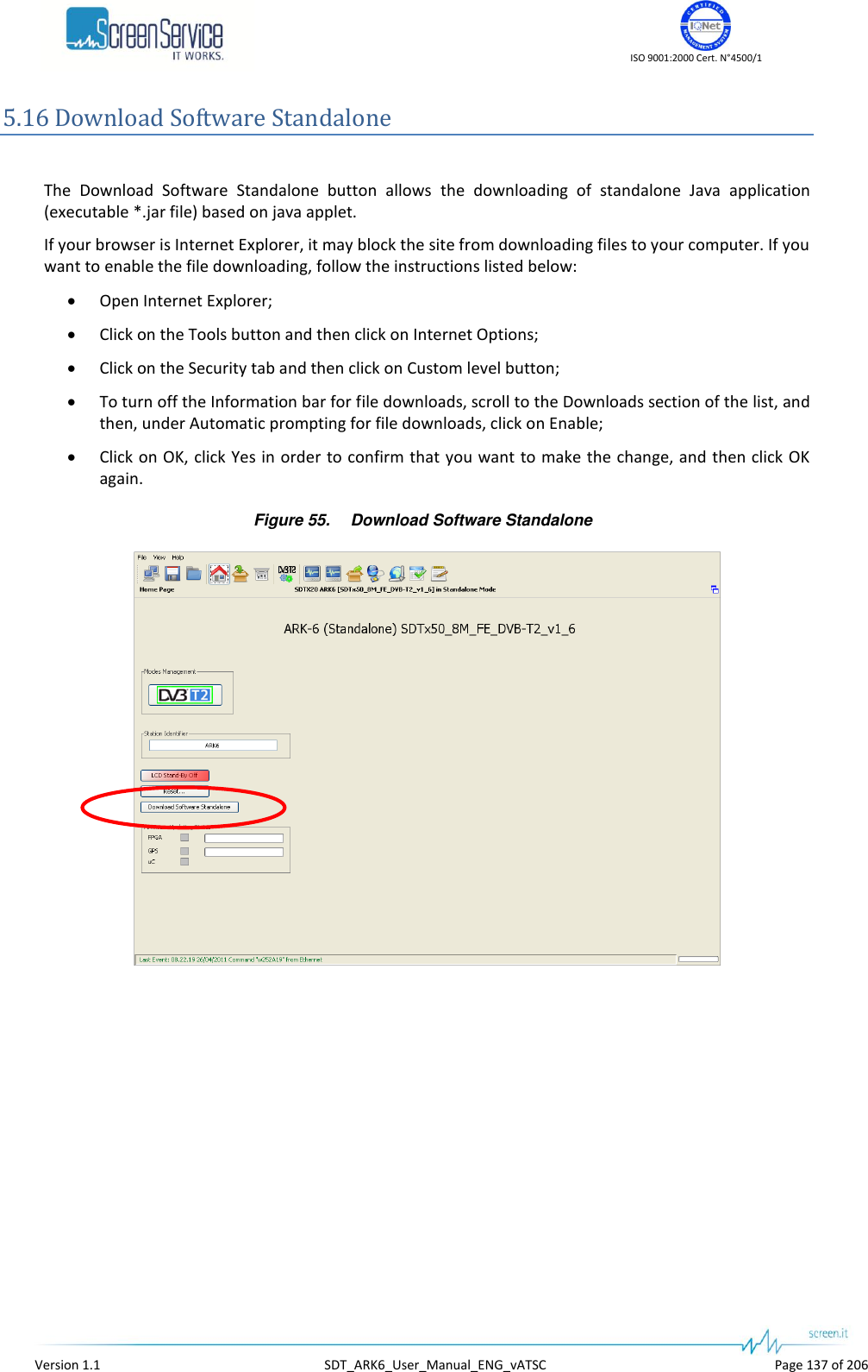
![ISO 9001:2000 Cert. N°4500/1 Version 1.1 SDT_ARK6_User_Manual_ENG_vATSC Page 133 of 206 5.15.2.1 Options window The Options window has two tabs: Time: Time Read Interval [s]; Alerts: the selection of events to display. Click on the Save button to save Java options; a new *.properties file will be created. The device is not loaded with a factory default *.properties file, but it is created and then stored in System File once properties are saved for the first time. 5.15.2.1.1 Time Figure 47. Time window This control allows changing the device-to-management PC java update time. The default value is 2 seconds. Click on Close button to quit this window. 5.15.2.1.2 Alerts Figure 48. Alerts window Alerts tab allows selecting which types of events will be notified through Alert boxes. Alerts appear on the right side of the monitor.](https://usermanual.wiki/Screen-Service-Broadcasting-Technologies/SDT201UB-ARK6/User-Guide-1671826-Page-133.png)
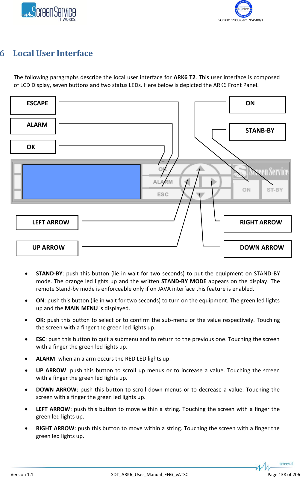
![ISO 9001:2000 Cert. N°4500/1 Version 1.1 SDT_ARK6_User_Manual_ENG_vATSC Page 139 of 206 6.1 Boot and Welcome Message Turning on the equipment, the display shows the progress bar as follow: Screen ServiceARK - DVB-T2System InitInit : [ ] Wait Screen ServiceARK - DVB-T2Boot FPGAInit : [ ] Wait Screen ServiceARK - DVB-T2Start systemInit : [ ] Wait Screen ServiceARK - DVB-T2Start systemInit : [ ] Ready When the boot is over, the device is ready. Screen ServiceARK - DVB-T2Start systemInit : [ ] Ready Screen ServiceARK - DVB-T2IP 10.77.98.44 Ready Press ESC to enter the main menu, otherwise after one minute waiting the idle status message appears.](https://usermanual.wiki/Screen-Service-Broadcasting-Technologies/SDT201UB-ARK6/User-Guide-1671826-Page-139.png)
![ISO 9001:2000 Cert. N°4500/1 Version 1.1 SDT_ARK6_User_Manual_ENG_vATSC Page 143 of 206 Alarm Alarm Message PS Voltage Out Of Range PS1V Out Of Range PS Current Out Of Range PS1I Out Of Range CPU Fan Error CPU Fan Error Test Mode Test Mode FE S2 Not Locked FE S2 not locked FE S2 S/N Low FE S2 SNR Low FE S2 BER High FE S2 BER high FE S2 Global Alarm [ATSC] No Input Input not valid [ATSC] Input Overflow Input overflow [ATSC] MH Err MH Error [ATSC] MEAS Demodulator Not Locked Meas Not Locked [ATSC] MEAS SNR Low Meas SNR Low [ATSC] FE Demodulator Not Locked FE Not Locked [ATSC] FE SNR Low FE SNR Low](https://usermanual.wiki/Screen-Service-Broadcasting-Technologies/SDT201UB-ARK6/User-Guide-1671826-Page-143.png)
![ISO 9001:2000 Cert. N°4500/1 Version 1.1 SDT_ARK6_User_Manual_ENG_vATSC Page 145 of 206 7.1 SNMP Protocol Preferences Go to SNMP Protocol Preferences. The following parameters should be set in order to correctly configure the SNMP Manager: SNMP protocol version: SNMPv1/SNMPv2; Read Community: the same of the one set in the Get field of Java interface, community section; Set Community: the same of the one set in the Set field of Java interface, community section; Timeout [s]: user defined; Retransmits: user defined; Port number: 161. Next figure illustrates how to configure SNMP Protocol Preferences using MG_SOFT MIB Browser as an example. Figure 56. SNMP Protocol Preferences](https://usermanual.wiki/Screen-Service-Broadcasting-Technologies/SDT201UB-ARK6/User-Guide-1671826-Page-145.png)
![ISO 9001:2000 Cert. N°4500/1 Version 1.1 SDT_ARK6_User_Manual_ENG_vATSC Page 148 of 206 Table 30. ARK6 SNMP Tree Structure OID Name R/W Description 1 iso 1.3 org 1.3.6 dod 1.3.6.1 internet 1.3.6.1.2 mgmt 1.3.6.1.2.1 mib-2 1.3.6.1.2.1.1 system 1.3.6.1.2.1.1.1 sysDescr R A textual description of the entity. This value includes the full name and version identification of the system" 1.3.6.1.2.1.1.2 sysObjectID R 1.3.6.1.2.1.1.3 sysUpTimeInstance R 1.3.6.1.2.1.1.4 sysContact R 1.3.6.1.2.1.1.5 sysName R Identification name of the equipment managed 1.3.6.1.2.1.1.6 sysLocation R 1.3.6.1.2.1.1.7 sysServices R 1.3.6.1.4 private 1.3.6.1.4.1 enterprise 1.3.6.1.4.1.21678 ssbt 1.3.6.1.4.1.21678.302 ssbtAtscModulation 1.3.6.1.4.1.21678.302.1 amMobileHandheld 1.3.6.1.4.1.21678.302.1.1 ammhPid RW ATSC M/H mode PID setting 1.3.6.1.4.1.21678.302.1.2 ammhEnable RW Enables ATSC M/H mode 1.3.6.1.4.1.21678.302.1.3 ammhFrameStatus R ATSC M/H frame alarm 1.3.6.1.4.1.21678.303 ssbtClock 1.3.6.1.4.1.21678.303.1 reference 1.3.6.1.4.1.21678.303.1.1 refClock RW Frequency reference selector 1.3.6.1.4.1.21678.303.2 gps 1.3.6.1.4.1.21678.303.2.1 satellites 1.3.6.1.4.1.21678.303.2.1.1 satVisible R Number of visible satellites. 1.3.6.1.4.1.21678.303.2.1.2 satTracked R Number of locked satellite. 1.3.6.1.4.1.21678.303.2.2 position 1.3.6.1.4.1.21678.303.2.2.1 positionLatitude R Latitude position [°] 1.3.6.1.4.1.21678.303.2.2.2 positionLongitude R Longitude position [°] 1.3.6.1.4.1.21678.303.2.3 utc](https://usermanual.wiki/Screen-Service-Broadcasting-Technologies/SDT201UB-ARK6/User-Guide-1671826-Page-148.png)
![ISO 9001:2000 Cert. N°4500/1 Version 1.1 SDT_ARK6_User_Manual_ENG_vATSC Page 149 of 206 OID Name R/W Description 1.3.6.1.4.1.21678.303.2.3.1 utcDate R UTC date and time as specified in SNMPv2-TC 1.3.6.1.4.1.21678.303.2.4 gpsLockStatus 1.3.6.1.4.1.21678.303.2.4.1 glsGps R GPS lock status derived from live data provided by the GPS receiver 1.3.6.1.4.1.21678.303.3 ocxo 1.3.6.1.4.1.21678.303.3.1 fineFreqAdjust RW Enables the Holdover mechanism 1.3.6.1.4.1.21678.303.3.2 dataToFlash R Sets the timeout of the Holdover in hour 1.3.6.1.4.1.21678.303.3.3 ocxoLockStatus 1.3.6.1.4.1.21678.303.3.3.1 olsGps R OCXO locked to the external GPS reference 1.3.6.1.4.1.21678.303.3.3.2 ols10Mhz R OCXO locked to the external 10 MHz reference 1.3.6.1.4.1.21678.303.3.3.3 ols1Pps R OCXO locked to the external 1PPS reference 1.3.6.1.4.1.21678.303.4 holdover 1.3.6.1.4.1.21678.303.4.1 hEnable RW Enables the Holdover mechanism 1.3.6.1.4.1.21678.303.4.2 hTimeout RW Sets the timeout of the Holdover in hour 1.3.6.1.4.1.21678.303.4.3 hStatus R The status of the Holdover mechanism 1.3.6.1.4.1.21678.303.4.4 hTmoStatus R The countdown of the Holdover timeout expressed in seconds 1.3.6.1.4.1.21678.306 ssbtHwMonitor 1.3.6.1.4.1.21678.306.1 reflexPower R Reflex power [dBm x 10] 1.3.6.1.4.1.21678.306.2 amplifierStatus R Amplifier status 1.3.6.1.4.1.21678.306.3 powerSupplies 1.3.6.1.4.1.21678.306.3.1 psNumber R The number of power supplies present on this system 1.3.6.1.4.1.21678.306.3.2 psTable NA 1.3.6.1.4.1.21678.306.3.2.1 psEntry 1.3.6.1.4.1.21678.306.3.2.1.1 psIndex R 1.3.6.1.4.1.21678.306.3.2.1.2 psDescr R Power supply description 1.3.6.1.4.1.21678.306.3.2.1.3 psVMeasUnit R Voltage unit of measurement 1.3.6.1.4.1.21678.306.3.2.1.4 psVoltage R Voltage indicator 1.3.6.1.4.1.21678.306.3.2.1.5 psCMeasUnit R Current unit of measurement 1.3.6.1.4.1.21678.306.3.2.1.6 psCurrent R Current indicator 1.3.6.1.4.1.21678.306.3.3 psRestart W Restarts the amplifier 1.3.6.1.4.1.21678.306.5 fans 1.3.6.1.4.1.21678.306.5.1 fansNumber R The number of fans present on this system 1.3.6.1.4.1.21678.306.5.2 fansTable NA 1.3.6.1.4.1.21678.306.5.2.1 fansEntry 1.3.6.1.4.1.21678.306.5.2.1.1 fansIndex R](https://usermanual.wiki/Screen-Service-Broadcasting-Technologies/SDT201UB-ARK6/User-Guide-1671826-Page-149.png)
![ISO 9001:2000 Cert. N°4500/1 Version 1.1 SDT_ARK6_User_Manual_ENG_vATSC Page 155 of 206 OID Name R/W Description 1.3.6.1.4.1.21678.307.3.1.3 t2fesIfAgc R Input IF AGC level 1.3.6.1.4.1.21678.307.3.1.4 t2fesRfAgc R Input RF AGC level 1.3.6.1.4.1.21678.307.3.1.5 t2fesTsLock R Demodulated TS Lock 1.3.6.1.4.1.21678.307.3.1.6 t2fesSyncStat R Sync statistics 1.3.6.1.4.1.21678.307.3.1.7 t2fesMer R Input MER [dBx1e3] 1.3.6.1.4.1.21678.307.3.1.8 t2fesSnr R Input SNR [dBx1e3] 1.3.6.1.4.1.21678.307.3.1.9 t2fesPreLdpcBer R Input Pre LDPC BER [1e7] 1.3.6.1.4.1.21678.307.3.1.10 t2fesPostBchFer R Input Post BCH FER [1e6] 1.3.6.1.4.1.21678.307.3.1.11 t2fesPreBchBer R Input Pre BCH BER [1e9] 1.3.6.1.4.1.21678.307.3.1.12 t2fesDemodPpm R Demodulated PPM [ppmx1e2] 1.3.6.1.4.1.21678.307.3.1.13 t2fesSignalQuality R Signal quality [%] 1.3.6.1.4.1.21678.307.3.1.14 t2fesBitrate R Expected bitrate 1.3.6.1.4.1.21678.307.3.1.15 t2fesLdpcIter R LDPC iterations per minute 1.3.6.1.4.1.21678.307.3.2 t2feL1Pre 1.3.6.1.4.1.21678.307.3.2.1 t2feL1PreType R Input stream type 1.3.6.1.4.1.21678.307.3.2.2 t2feL1PreBwt R BWT extension indicator 1.3.6.1.4.1.21678.307.3.2.3 t2feL1PreS1 R S1 field 1.3.6.1.4.1.21678.307.3.2.4 t2feL1PreS2 R S2 field 1.3.6.1.4.1.21678.307.3.2.5 t2feL1PreFftSize R FFT size 1.3.6.1.4.1.21678.307.3.2.6 t2feL1PreMixed R Mixed indicator 1.3.6.1.4.1.21678.307.3.2.7 t2feL1PreL1Repeat R L1 repeat enable flag 1.3.6.1.4.1.21678.307.3.2.8 t2feL1PreGuardInterval R Guard Interval 1.3.6.1.4.1.21678.307.3.2.9 t2feL1PrePapr R PAPR 1.3.6.1.4.1.21678.307.3.2.10 t2feL1PreL1Mod R L1 modulation scheme 1.3.6.1.4.1.21678.307.3.2.11 t2feL1PreL1CodeRate R L1 code rate 1.3.6.1.4.1.21678.307.3.2.12 t2feL1PreL1Fec R L1 FEC Type 1.3.6.1.4.1.21678.307.3.2.13 t2feL1PreL1PostSize R L1 Post Size 1.3.6.1.4.1.21678.307.3.2.14 t2feL1PreL1PostInfoSize R L1 Post Info Size 1.3.6.1.4.1.21678.307.3.2.15 t2feL1PrePilotPattern R Pilot Pattern 1.3.6.1.4.1.21678.307.3.2.16 t2feL1PreTxIdAvailability R TX Id 1.3.6.1.4.1.21678.307.3.2.17 t2feL1PreCellId R Cell Id 1.3.6.1.4.1.21678.307.3.2.18 t2feL1PreT2NetworkId R T2 Network Id 1.3.6.1.4.1.21678.307.3.2.19 t2feL1PreT2SystemId R T2 System Id 1.3.6.1.4.1.21678.307.3.2.20 t2feL1PreNumT2Frames R Number of T2 frames 1.3.6.1.4.1.21678.307.3.2.21 t2feL1PreNumDataSymb R Number of data symbols 1.3.6.1.4.1.21678.307.3.2.22 t2feL1PreRegenFlag R Regeneration count indicator](https://usermanual.wiki/Screen-Service-Broadcasting-Technologies/SDT201UB-ARK6/User-Guide-1671826-Page-155.png)
![ISO 9001:2000 Cert. N°4500/1 Version 1.1 SDT_ARK6_User_Manual_ENG_vATSC Page 157 of 206 OID Name R/W Description 1.3.6.1.4.1.21678.307.3.3.7.2.1.12 t2feL1PostPlpFec R The FEC type used by the associated PLP 1.3.6.1.4.1.21678.307.3.3.7.2.1.13 t2feL1PostNumBlocksMax R Maximum number of PLP blocks 1.3.6.1.4.1.21678.307.3.3.7.2.1.14 t2feL1PostFrameInterval R Frame interval 1.3.6.1.4.1.21678.307.3.3.7.2.1.15 t2feL1PostTimeIntLength R Time interleaving length 1.3.6.1.4.1.21678.307.3.3.7.2.1.16 t2feL1PostTimeIntType R Time interleaving type 1.3.6.1.4.1.21678.307.3.3.7.2.1.17 t2feL1PostInbandA R In-band A flag 1.3.6.1.4.1.21678.307.3.3.7.2.1.18 t2feL1PostInbandB R In-band B flag 1.3.6.1.4.1.21678.307.3.3.7.2.1.19 t2feL1PostPlpMode R PLP mode 1.3.6.1.4.1.21678.307.3.3.7.2.1.20 t2feL1PostStaticFlag R Static flag 1.3.6.1.4.1.21678.307.3.3.7.2.1.21 t2feL1PostStaticPaddFlag R Static padding flag 1.3.6.1.4.1.21678.307.4 tFrontEnd 1.3.6.1.4.1.21678.307.4.1 tfeStatistics 1.3.6.1.4.1.21678.307.4.1.1 tfesRxLevel R Input RX level 127: over input -128: low power -63...62: power expressed in dB 1.3.6.1.4.1.21678.307.4.1.2 tfesCarrierOffset R Input carrier offset 1.3.6.1.4.1.21678.307.4.1.3 tfesIfAgc R Input IF AGC level 1.3.6.1.4.1.21678.307.4.1.4 tfesRfAgc R Input RF AGC level 1.3.6.1.4.1.21678.307.4.1.5 tfesTsLock R Demodulated TS Lock 1.3.6.1.4.1.21678.307.4.1.6 tfesSyncStat R Sync statistics 1.3.6.1.4.1.21678.307.4.1.7 tfesMer R Input MER [dBx1e3] 1.3.6.1.4.1.21678.307.4.1.8 tfesSnr R Input SNR [dBx1e3] 1.3.6.1.4.1.21678.307.4.1.9 tfesPreVitBer R Input Pre Viterbi BER [1e7] 1.3.6.1.4.1.21678.307.4.1.10 tfesPreRsBer R Input Pre RS BER [1e7] 1.3.6.1.4.1.21678.307.4.1.11 tfesRsErrCount R Input RS errors count detected by the RS decoder over 1 second 1.3.6.1.4.1.21678.307.4.1.12 tfesDemodPpm R Demodulated PPM [ppmx1e2] 1.3.6.1.4.1.21678.307.4.1.13 tfesSignalQuality R Signal quality [%] 1.3.6.1.4.1.21678.307.4.1.14 tfesBitrate R Expected bitrate 1.3.6.1.4.1.21678.307.4.2 tfeDemodParams 1.3.6.1.4.1.21678.307.4.2.1 tfedpConstellation R Constellation for current modulation scheme 1.3.6.1.4.1.21678.307.4.2.2 tfedpHierMode R Hierarchy information for current modulation scheme 1.3.6.1.4.1.21678.307.4.2.3 tfedpHpCodeRate R High Priority Code Rate 1.3.6.1.4.1.21678.307.4.2.4 tfedpLpCodeRate R Low Priority Code Rate 1.3.6.1.4.1.21678.307.4.2.5 tfedpFft R FFT size 1.3.6.1.4.1.21678.307.4.2.6 tfedpGuardInterval R Guard interval 1.3.6.1.4.1.21678.307.4.2.7 tfedpCelllId R Cell identifier](https://usermanual.wiki/Screen-Service-Broadcasting-Technologies/SDT201UB-ARK6/User-Guide-1671826-Page-157.png)
![ISO 9001:2000 Cert. N°4500/1 Version 1.1 SDT_ARK6_User_Manual_ENG_vATSC Page 158 of 206 OID Name R/W Description 1.3.6.1.4.1.21678.307.5 s2FrontEnd 1.3.6.1.4.1.21678.307.5.1 s2feSettngs 1.3.6.1.4.1.21678.307.5.1.1 s2feFrequency RW Frequency [MHz] 1.3.6.1.4.1.21678.307.5.1.2 s2feSymbolRate RW Symbol Rate [KBaud] 1.3.6.1.4.1.21678.307.5.1.3 s2fePolarization RW Polarization 1.3.6.1.4.1.21678.307.5.1.4 s2feIsiA RW Input Stream Identifier A 1.3.6.1.4.1.21678.307.5.1.5 s2feIsiB RW Input Stream Identifier B 1.3.6.1.4.1.21678.307.5.1.6 s2fePls 1.3.6.1.4.1.21678.307.5.1.6.1 s2fepMode RW Mode selector 1.3.6.1.4.1.21678.307.5.1.6.2 s2fepN0 RW PLS number 0 setting 1.3.6.1.4.1.21678.307.5.1.6.3 s2fepN1 RW PLS number 1 setting 1.3.6.1.4.1.21678.307.5.1.6.4 s2fepN2 RW PLS number 2 setting 1.3.6.1.4.1.21678.307.5.2 s2feDemodParams 1.3.6.1.4.1.21678.307.5.2.1 s2fedpRxLevel R Input RX level [dBm] 1.3.6.1.4.1.21678.307.5.2.2 s2fedpLock R Transponder lock status 1.3.6.1.4.1.21678.307.5.2.3 s2fedpStandard R Input standard 1.3.6.1.4.1.21678.307.5.2.4 s2fedpRxModCode R Modulation mode 1.3.6.1.4.1.21678.307.5.2.5 s2fedpBand R Band 1.3.6.1.4.1.21678.307.5.2.6 s2fedpMode R Mode 1.3.6.1.4.1.21678.307.5.2.7 s2fedpSnr R S/N level [dB * 10] 1.3.6.1.4.1.21678.307.5.2.8 s2fedpPilots R Pilots 1.3.6.1.4.1.21678.307.5.2.9 s2fedpRollOff R Roll off 1.3.6.1.4.1.21678.307.5.2.10 s2fedpConstellation R Constellation 1.3.6.1.4.1.21678.307.5.2.11 s2fedpBer R Bit Error Rate (* 10^7) 1.3.6.1.4.1.21678.307.6 isdbtFrontEnd 1.3.6.1.4.1.21678.307.6.1 ifeStatistics 1.3.6.1.4.1.21678.307.6.1.1 ifesRxLevel R Input RX level 127: over input -128: low power -63...62: power expressed in dB 1.3.6.1.4.1.21678.307.6.1.2 ifesIfLevel R Input IF level 1.3.6.1.4.1.21678.307.6.1.3 ifesIfAgcDac R IF AGC output DAC value 1.3.6.1.4.1.21678.307.6.1.4 ifesDemState R The state of the sequencer 1.3.6.1.4.1.21678.307.6.1.5 ifesMode R Input mode 1.3.6.1.4.1.21678.307.6.1.6 ifesGuardInterval R Input guard interval 1.3.6.1.4.1.21678.307.6.1.7 ifesSTRFreqErr R Frequency error detected by symbol timing recovery [Hz] 1.3.6.1.4.1.21678.307.6.1.8 ifesCRFreqErr R Frequency error detected by carrier recovery [kHz] 1.3.6.1.4.1.21678.307.6.1.9 ifesCN R Estimated Carrier to Noise ratio (dB x 10)](https://usermanual.wiki/Screen-Service-Broadcasting-Technologies/SDT201UB-ARK6/User-Guide-1671826-Page-158.png)
![ISO 9001:2000 Cert. N°4500/1 Version 1.1 SDT_ARK6_User_Manual_ENG_vATSC Page 159 of 206 OID Name R/W Description 1.3.6.1.4.1.21678.307.6.2 ifeLayerStatistics 1.3.6.1.4.1.21678.307.6.2.1 ifelsNumber R The number of Layers 1.3.6.1.4.1.21678.307.6.2.2 ifelsTable NA 1.3.6.1.4.1.21678.307.6.2.2.1 ifelsEntry 1.3.6.1.4.1.21678.307.6.2.2.1.1 ifelsIndex R 1.3.6.1.4.1.21678.307.6.2.2.1.2 ifelsDescr R Layer description 1.3.6.1.4.1.21678.307.6.2.2.1.3 ifelsMod R Modulation scheme 1.3.6.1.4.1.21678.307.6.2.2.1.4 ifelsCodeRate R Code rate 1.3.6.1.4.1.21678.307.6.2.2.1.5 ifelsTILength R Time Interleaving length 1.3.6.1.4.1.21678.307.6.2.2.1.6 ifelsSegNum R Number of segments 1.3.6.1.4.1.21678.307.6.2.2.1.7 ifelsMer R MER [dB] (* 10) 1.3.6.1.4.1.21678.307.6.2.2.1.8 ifelsPreVitBer R Pre-Viterbi BER (* 10^9) 1.3.6.1.4.1.21678.307.6.2.2.1.9 ifelsPostVitBer R Post-Viterbi BER (* 10^9) 1.3.6.1.4.1.21678.307.6.2.2.1.10 ifelsPktErrRate R Packet Error Rate (* 10^9) 1.3.6.1.4.1.21678.307.7 atscFrontEnd 1.3.6.1.4.1.21678.307.7.1 afeStatistics 1.3.6.1.4.1.21678.307.7.1.1 afesFrequencyOffset R Input carrier offset 1.3.6.1.4.1.21678.307.7.1.2 afesDemodStatus R VSB demodulation status 1.3.6.1.4.1.21678.307.7.1.3 afesEqStatus R Equalizer status 1.3.6.1.4.1.21678.307.7.1.4 afesDemLock R Demodulator lock status 1.3.6.1.4.1.21678.307.7.1.5 afesAgcLock R Digital AGC lock status 1.3.6.1.4.1.21678.307.7.1.6 afesFrameLock R Frame lock status 1.3.6.1.4.1.21678.307.7.1.7 afesCarrierFreqLoopLock R Carrier frequency loop lock status 1.3.6.1.4.1.21678.307.7.1.8 afesTimingFreqLoopLock R Timing frequency loop lock status 1.3.6.1.4.1.21678.307.7.1.9 afesSnr R Signal to Noise Ratio [dB] 1.3.6.1.4.1.21678.307.7.1.10 afesSer R Segment Error Rate 1.3.6.1.4.1.21678.307.7.1.11 afesBer R Bit Error Rate 1.3.6.1.4.1.21678.308 ssbtIsdbtModulation 1.3.6.1.4.1.21678.308.1 imSettings 1.3.6.1.4.1.21678.308.1.1 imsIipStatus 1.3.6.1.4.1.21678.308.1.1.1 imsisValid R Input IIP valid 1.3.6.1.4.1.21678.308.1.1.2 imsisAlarm R Input IIP alarm 1.3.6.1.4.1.21678.308.1.2 imsNetworkMode RW Transmitter network mode selector 1.3.6.1.4.1.21678.308.1.3 imsEquipmentId RW Equipment ID 1.3.6.1.4.1.21678.308.1.4 imsDefIip R Equipment ID found in IIP 1.3.6.1.4.1.21678.308.1.5 imsNetworkDelay R Network delay [100ns]](https://usermanual.wiki/Screen-Service-Broadcasting-Technologies/SDT201UB-ARK6/User-Guide-1671826-Page-159.png)
![ISO 9001:2000 Cert. N°4500/1 Version 1.1 SDT_ARK6_User_Manual_ENG_vATSC Page 160 of 206 OID Name R/W Description 1.3.6.1.4.1.21678.308.1.6 imsEWS 1.3.6.1.4.1.21678.308.1.6.1 imsewsEnable RW Enables the local editing of the Emergency switch on control flag 1.3.6.1.4.1.21678.308.1.6.2 imsewsSetting RW Sets the Emergency switch on control flag 1.3.6.1.4.1.21678.308.1.7 imsLayersMonitor 1.3.6.1.4.1.21678.308.1.7.1 imslmNumber R The number of Layers 1.3.6.1.4.1.21678.308.1.7.2 imslmTable NA 1.3.6.1.4.1.21678.308.1.7.2.1 imslmEntry 1.3.6.1.4.1.21678.308.1.7.2.1.1 imslmIndex R 1.3.6.1.4.1.21678.308.1.7.2.1.2 imslmDescr R Layer description 1.3.6.1.4.1.21678.308.1.7.2.1.3 imslmPktXFrame R Number of packets per frame 1.3.6.1.4.1.21678.308.1.7.2.1.4 imslmOverflow R Overflow 1.3.6.1.4.1.21678.308.1.7.2.1.5 imslmUnderflow R Underflow 1.3.6.1.4.1.21678.308.2 imIipParams 1.3.6.1.4.1.21678.308.2.1 imipMode R IIP modulator mode. 1.3.6.1.4.1.21678.308.2.2 imipGuardInterval R IIP modulator guard interval. 1.3.6.1.4.1.21678.308.2.3 imipUsePartialReceptionFlag R IIP modulator use the Partial Reception Flag. 1.3.6.1.4.1.21678.308.2.4 imipMaxDelay R IIP maximum delay [100 ns]. 1.3.6.1.4.1.21678.308.2.5 imipSyncId R IIP modulator use the Synchronization ID. 1.3.6.1.4.1.21678.308.2.6 imipStaticDelay R IIP modulator use the Time Reference. 1.3.6.1.4.1.21678.308.2.7 imipTimeOffset R IIP time offset [100 ns]. 1.3.6.1.4.1.21678.308.2.8 imipLayers 1.3.6.1.4.1.21678.308.2.8.1 imiplNumber R The number of Layers 1.3.6.1.4.1.21678.308.2.8.2 imiplTable NA 1.3.6.1.4.1.21678.308.2.8.2.1 imiplEntry 1.3.6.1.4.1.21678.308.2.8.2.1.1 imiplIndex R 1.3.6.1.4.1.21678.308.2.8.2.1.2 imiplDescr R Layer description 1.3.6.1.4.1.21678.308.2.8.2.1.3 imiplMod R Modulation scheme 1.3.6.1.4.1.21678.308.2.8.2.1.4 imiplCodeRate R Code rate of inner code 1.3.6.1.4.1.21678.308.2.8.2.1.5 imiplTILength R Time Interleaving length 1.3.6.1.4.1.21678.308.2.8.2.1.6 imiplSegNum R Number of segments 1.3.6.1.4.1.21678.308.3 imLocalParams 1.3.6.1.4.1.21678.308.3.1 imlpMode RW Modulator mode. 1.3.6.1.4.1.21678.308.3.2 imlpGuardInterval RW Modulator guard interval. 1.3.6.1.4.1.21678.308.3.3 imlpUsePartialReceptionFlag RW Use the Partial Reception Flag. 1.3.6.1.4.1.21678.308.3.4 imlpUserDelay RW User delay [100 ns].](https://usermanual.wiki/Screen-Service-Broadcasting-Technologies/SDT201UB-ARK6/User-Guide-1671826-Page-160.png)
![ISO 9001:2000 Cert. N°4500/1 Version 1.1 SDT_ARK6_User_Manual_ENG_vATSC Page 161 of 206 OID Name R/W Description 1.3.6.1.4.1.21678.308.3.5 imlpLayers 1.3.6.1.4.1.21678.308.3.5.1 imlplNumber R The number of Layers 1.3.6.1.4.1.21678.308.3.5.2 imlplTable NA 1.3.6.1.4.1.21678.308.3.5.2.1 imlplEntry 1.3.6.1.4.1.21678.308.3.5.2.1.1 imlplIndex R 1.3.6.1.4.1.21678.308.3.5.2.1.2 imlplDescr RW Layer description 1.3.6.1.4.1.21678.308.3.5.2.1.3 imlplMod RW Modulation scheme 1.3.6.1.4.1.21678.308.3.5.2.1.4 imlplCodeRate RW Code rate of inner code 1.3.6.1.4.1.21678.308.3.5.2.1.5 imlplTILength RW Time Interleaving length 1.3.6.1.4.1.21678.308.3.5.2.1.6 imlplSegNum RW Number of segments 1.3.6.1.4.1.21678.308.4 imCurrentParams 1.3.6.1.4.1.21678.308.4.1 imcpMode R Current modulator mode. 1.3.6.1.4.1.21678.308.4.2 imcpGuardInterval R Current modulator guard interval. 1.3.6.1.4.1.21678.308.4.3 imcpUsePartialReceptionFlag R Use the Partial Reception Flag. 1.3.6.1.4.1.21678.308.4.4 imcpSystemDelay R Current system delay [100 ns]. 1.3.6.1.4.1.21678.308.4.5 imcpLayers 1.3.6.1.4.1.21678.308.4.5.1 imcplNumber R The number of Layers 1.3.6.1.4.1.21678.308.4.5.2 imcplTable NA 1.3.6.1.4.1.21678.308.4.5.2.1 imcplEntry 1.3.6.1.4.1.21678.308.4.5.2.1.1 imcplIndex R 1.3.6.1.4.1.21678.308.4.5.2.1.2 imcplDescr R Layer description 1.3.6.1.4.1.21678.308.4.5.2.1.3 imcplMod R Modulation scheme 1.3.6.1.4.1.21678.308.4.5.2.1.4 imcplCodeRate R Code rate of inner code 1.3.6.1.4.1.21678.308.4.5.2.1.5 imcplTILength R Time Interleaving length 1.3.6.1.4.1.21678.308.4.5.2.1.6 imcplSegNum R Number of segments 1.3.6.1.4.1.21678.309 ssbtItuModulation 1.3.6.1.4.1.21678.309.1 itumVideoSettings 1.3.6.1.4.1.21678.309.1.1 itumvsWhitelevel RW White level [%] (range 10 to 22) = [(x*0.05) + 10] (x: range 0 to 240) 1.3.6.1.4.1.21678.309.1.2 itumvsSynchAmplitude RW Synch Amplitude [%] (range: 22 to 27,5) = [(x*0.05) + 20] (x: range 40 to 150) 1.3.6.1.4.1.21678.309.1.3 itumvsPedesLevel RW Pedes level [%] (range: 0 to 7) = (x*0.05) (x: range 0 to 140) 1.3.6.1.4.1.21678.309.2 itumAudioSettings 1.3.6.1.4.1.21678.309.2.1 itumasDeviation RW Audio deviation level 1.3.6.1.4.1.21678.309.2.2 itumasSoundSystem RW Sound System selector](https://usermanual.wiki/Screen-Service-Broadcasting-Technologies/SDT201UB-ARK6/User-Guide-1671826-Page-161.png)
![ISO 9001:2000 Cert. N°4500/1 Version 1.1 SDT_ARK6_User_Manual_ENG_vATSC Page 162 of 206 OID Name R/W Description 1.3.6.1.4.1.21678.309.2.3 itumasCarrierLevel1 RW Carrier Level 1 [dB] (range: -7 to -22) = [-1* (x/10)] (range 70 to 220) 1.3.6.1.4.1.21678.309.2.4 itumasCarrierLevel2 RW Carrier Level 2 [dB] (range: -7 to -22) = [-1* (x/10)] (range 70 to 220) 1.3.6.1.4.1.21678.309.2.5 itumasEmphasis R Emphasis monitor 1.3.6.1.4.1.21678.309.2.6 itumasType RW Selects the audio type 1.3.6.1.4.1.21678.309.3 itumGroupDelay 1.3.6.1.4.1.21678.309.3.1 itumgdCurveSelector RW Mode selector for group delay filter 1.3.6.1.4.1.21678.310 ssbtOutput 1.3.6.1.4.1.21678.310.1 outputSettings 1.3.6.1.4.1.21678.310.1.1 osOutputManagement 1.3.6.1.4.1.21678.310.1.1.3 osomOutPower RW Output power 1.3.6.1.4.1.21678.310.1.1.4 osomRflManagement 1.3.6.1.4.1.21678.310.1.1.4.1 osomrmNumberAttempts RW Number of attempts to restore the system after a Reflex Power warning 1.3.6.1.4.1.21678.310.1.1.4.2 osomrmStatus R Reflex Power status 1.3.6.1.4.1.21678.310.1.1.4.3 osomrmRflHigh R Shows if the Reflex Power High goes over the alarm threshold 1.3.6.1.4.1.21678.310.1.1.4.4 osomrmCurrNumAttempt R Shows the current number of attemp to restore the system after a Reflex Power warning 1.3.6.1.4.1.21678.310.1.1.4.5 osomrmAttemptTimeout R Shows the coutdown expressed in seconds between two attemps 1.3.6.1.4.1.21678.310.1.1.4.6 osomrmReset W Resets the output amplifier stage once the device is in Reflex Power Alarm 1.3.6.1.4.1.21678.310.1.1.4.7 osomrmResetTimeout R Shows the coutdown expressed in seconds to come back from Warning to Ok state 1.3.6.1.4.1.21678.310.1.1.5 osomT2Output 1.3.6.1.4.1.21678.310.1.1.5.1 osomt2oRfChannel RW Output channel 1.3.6.1.4.1.21678.310.1.1.5.2 osomt2RfFreqOff RW Output frequency offset expressed in Hz (from -200 kHz up to 200 kHz) 1.3.6.1.4.1.21678.310.1.1.6 osomTOutput 1.3.6.1.4.1.21678.310.1.1.6.1 osomtoRfChannel RW Output channel 1.3.6.1.4.1.21678.310.1.1.6.2 osomtoRfFreqOff RW Output frequency offset expressed in Hz (from -200 kHz up to 200 kHz) 1.3.6.1.4.1.21678.310.1.1.7 osomIOutput 1.3.6.1.4.1.21678.310.1.1.7.1 osomioRfChannel RW Output channel](https://usermanual.wiki/Screen-Service-Broadcasting-Technologies/SDT201UB-ARK6/User-Guide-1671826-Page-162.png)
![ISO 9001:2000 Cert. N°4500/1 Version 1.1 SDT_ARK6_User_Manual_ENG_vATSC Page 164 of 206 OID Name R/W Description 1.3.6.1.4.1.21678.310.3.2.1 tsEntry 1.3.6.1.4.1.21678.310.3.2.1.1 tsIndex R 1.3.6.1.4.1.21678.310.3.2.1.2 tsDescr R Test signal description. 1.3.6.1.4.1.21678.310.3.2.1.3 tsEnable RW Test signal enable 0: disabled 1: enabled. 1.3.6.1.4.1.21678.310.3.3 tsItu 1.3.6.1.4.1.21678.310.3.3.1 video 1.3.6.1.4.1.21678.310.3.3.1.1 videoTestSel RW Video test signal selector 1.3.6.1.4.1.21678.310.3.3.2 audio 1.3.6.1.4.1.21678.310.3.3.2.1 audioToneEnable RW Enables the audio test tones 1.3.6.1.4.1.21678.310.3.3.2.2 audioToneRight RW Right tone frequency (range:0 to127) [unit x 100Hz] 1.3.6.1.4.1.21678.310.3.3.2.3 audioToneLeft RW Left tone frequency (range:0 to127) [unit x 100Hz] 1.3.6.1.4.1.21678.310.3.3.2.4 audioMuteEnable RW Enables the audio muting 1.3.6.1.4.1.21678.310.3.3.3 its 1.3.6.1.4.1.21678.310.3.3.3.1 itsEnable RW Enables ITS test signal insertion 1.3.6.1.4.1.21678.310.3.3.3.2 its0 RW ITS number 0 position 1.3.6.1.4.1.21678.310.3.3.3.3 its1 RW ITS number 1 position 1.3.6.1.4.1.21678.310.3.3.3.4 its2 RW ITS number 2 position 1.3.6.1.4.1.21678.310.3.3.3.5 its3 RW ITS number 3 position 1.3.6.1.4.1.21678.310.3.3.3.6 its4 RW ITS number 4 position 1.3.6.1.4.1.21678.310.4 outputMonitor 1.3.6.1.4.1.21678.310.4.1 omFwdPower R Forward power [dBm x 10] indicator 1.3.6.1.4.1.21678.310.4.2 omAgcMode R AGC mode status 0: analog 1: digital 1.3.6.1.4.1.21678.310.4.3 omAgcOn R Auto AGC status 0: off 1: on 1.3.6.1.4.1.21678.310.5 standBy 1.3.6.1.4.1.21678.310.5.1 sbEnable RW LCD stand-by button enable 1.3.6.1.4.1.21678.310.5.2 sbStatus R Current device mode 1.3.6.1.4.1.21678.311 ssbtTsOverIP 1.3.6.1.4.1.21678.311.1 inputChannels 1.3.6.1.4.1.21678.311.1.1 icIgmpEnable RW IGMP enable 1.3.6.1.4.1.21678.311.1.2 icNumber R Number of input Ethernet channels. 1.3.6.1.4.1.21678.311.1.3 icTable NA 1.3.6.1.4.1.21678.311.1.3.1 icEntry 1.3.6.1.4.1.21678.311.1.3.1.1 icIndex R 1.3.6.1.4.1.21678.311.1.3.1.2 icDescr R Description of input channel 1.3.6.1.4.1.21678.311.1.3.1.3 icLocalIpAddr RW IP address 1.3.6.1.4.1.21678.311.1.3.1.4 icLocalPort RW Port](https://usermanual.wiki/Screen-Service-Broadcasting-Technologies/SDT201UB-ARK6/User-Guide-1671826-Page-164.png)
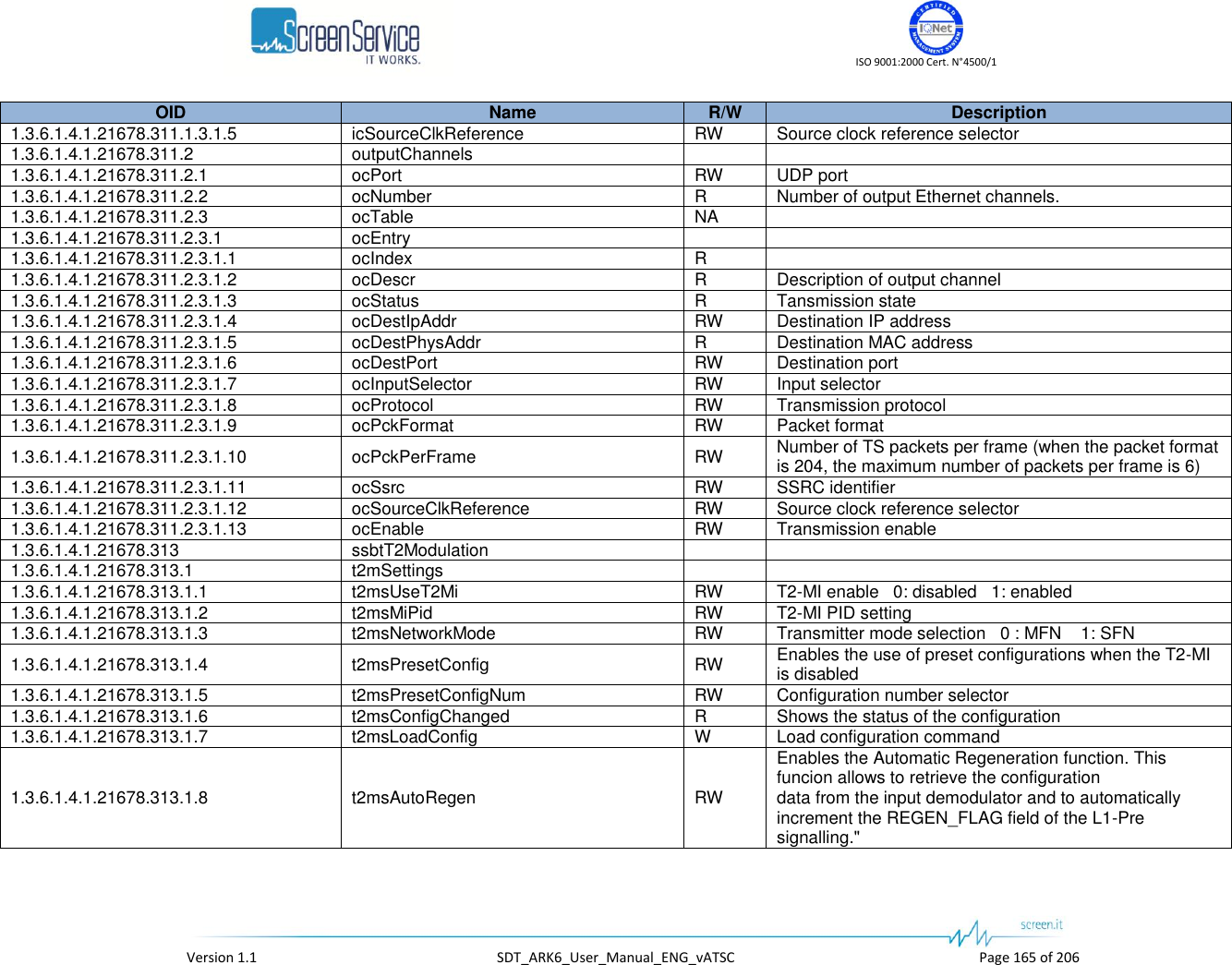
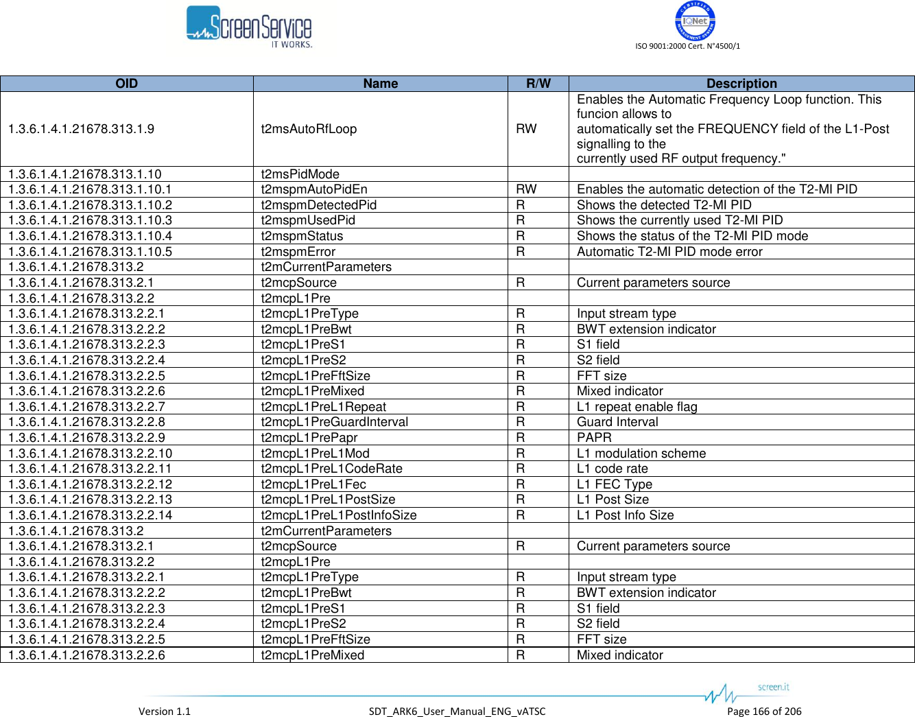
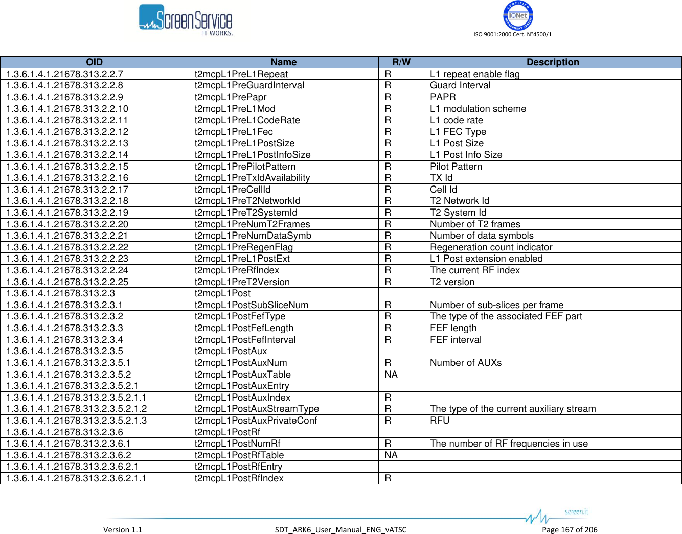
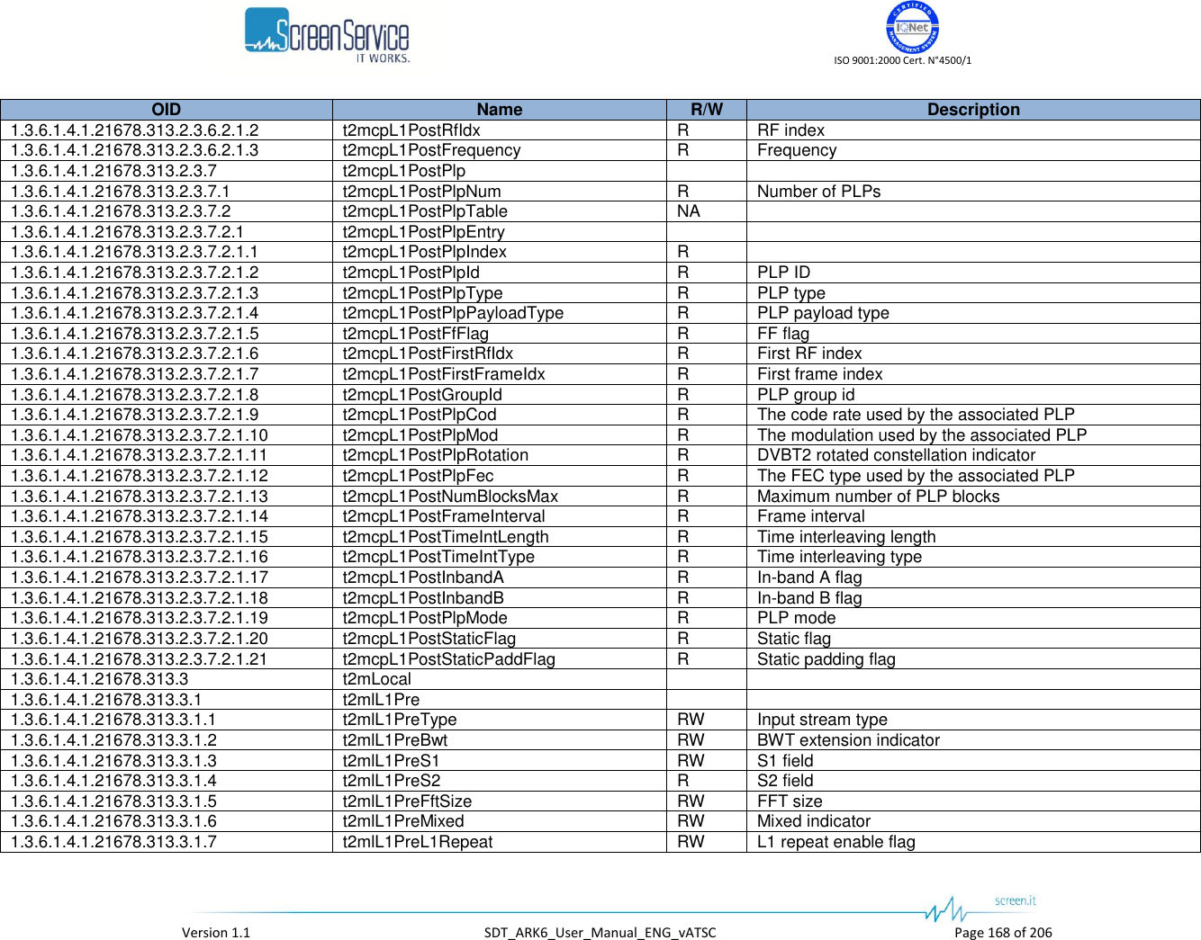
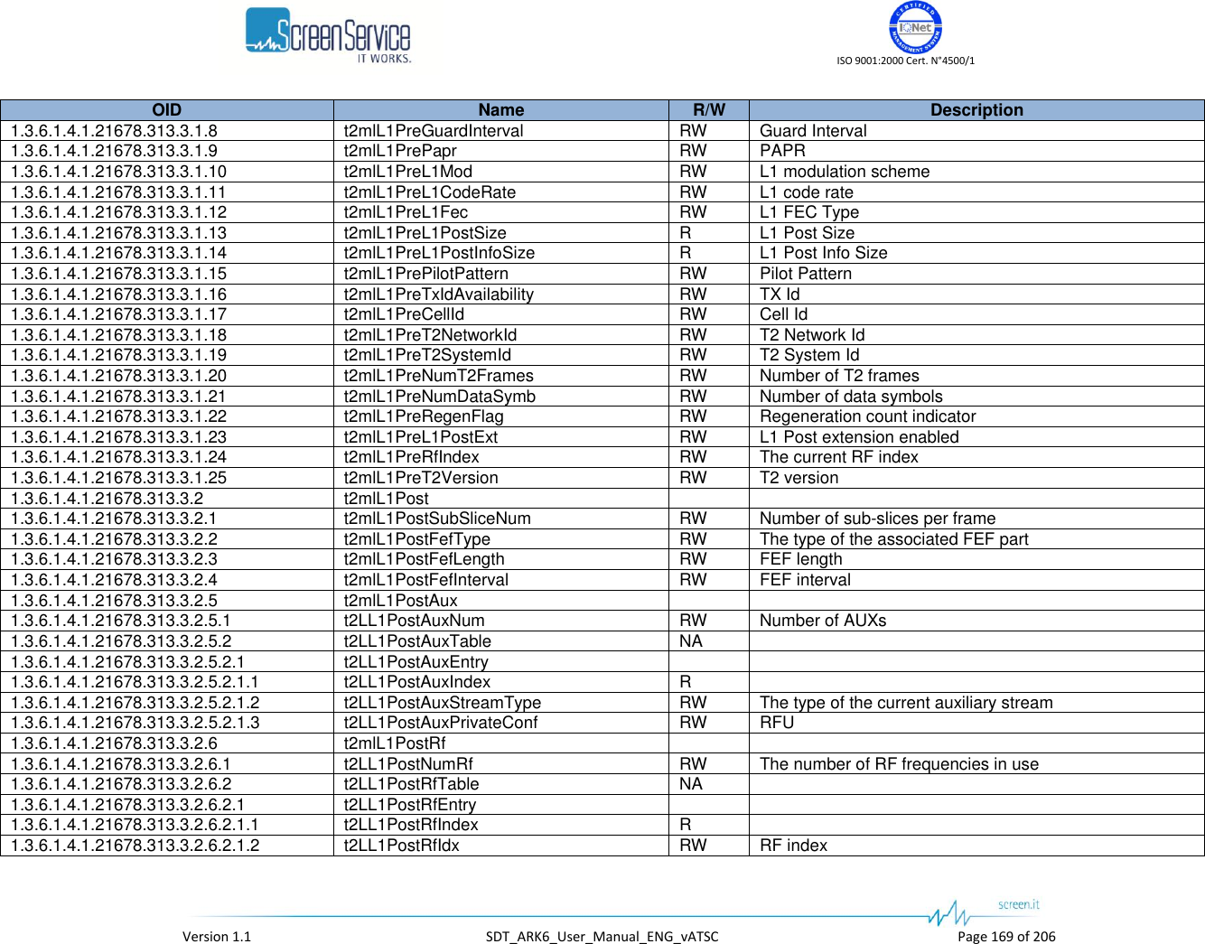
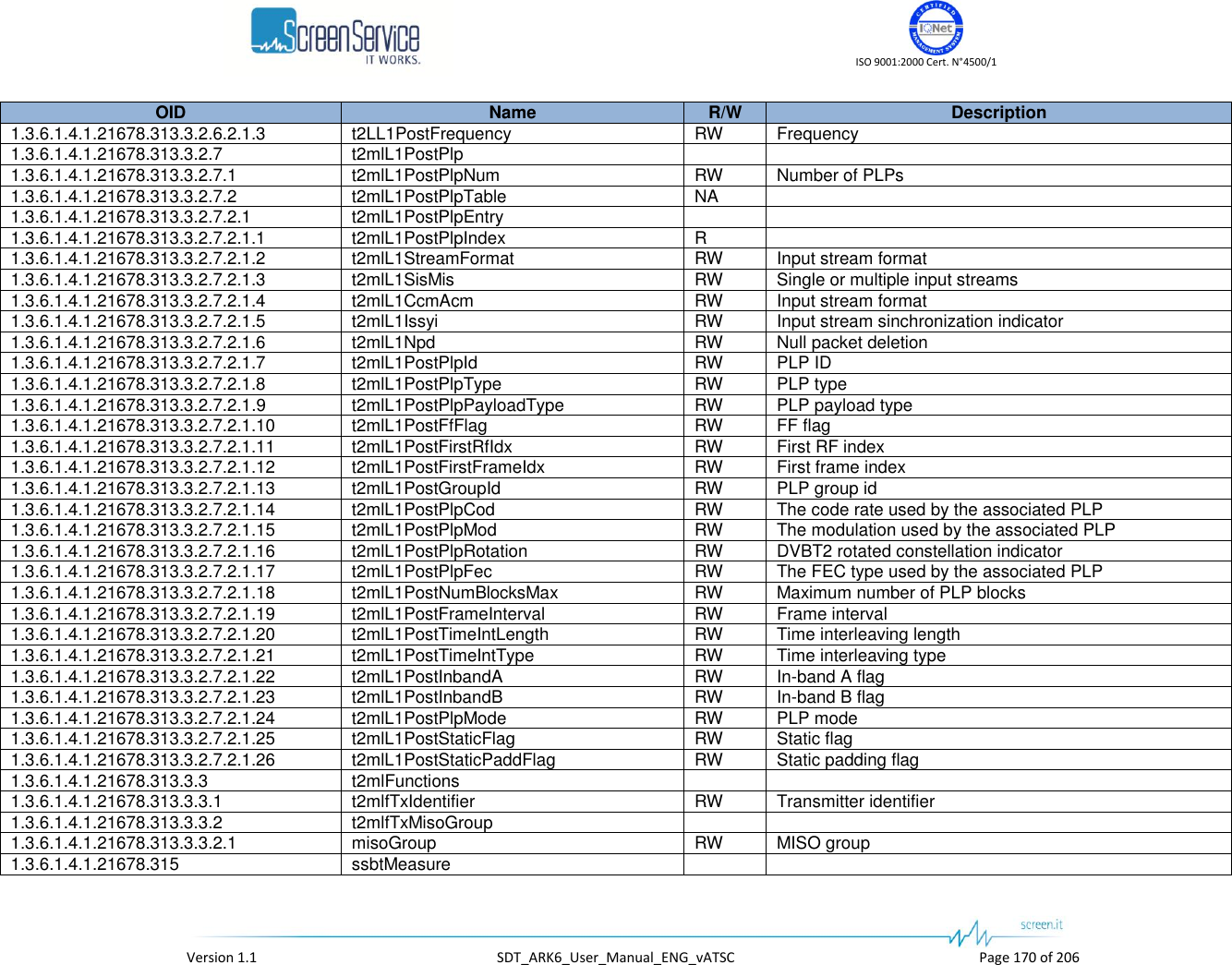
![ISO 9001:2000 Cert. N°4500/1 Version 1.1 SDT_ARK6_User_Manual_ENG_vATSC Page 171 of 206 OID Name R/W Description 1.3.6.1.4.1.21678.315.1 t2Measure 1.3.6.1.4.1.21678.315.1.1 t2mStatistics 1.3.6.1.4.1.21678.315.1.1.1 meas1RxLevel R Output RX level 127: over input -128: low power -63...62: power expressed in dB 1.3.6.1.4.1.21678.315.1.1.2 meas2RxLevel R Output RX level 127: over input -128: low power -63...62: power expressed in dB 1.3.6.1.4.1.21678.315.1.1.3 measCarrierOffset R Output carrier offset 1.3.6.1.4.1.21678.315.1.1.4 measIfAgc R Output IF AGC level 1.3.6.1.4.1.21678.315.1.1.5 measRfAgc R Output RF AGC level 1.3.6.1.4.1.21678.315.1.1.6 measTsLock R Demodulated TS Lock 1.3.6.1.4.1.21678.315.1.1.7 measSyncStat R Sync statistics 1.3.6.1.4.1.21678.315.1.1.8 measMer R Output MER [dBx1e3] 1.3.6.1.4.1.21678.315.1.1.9 measSnr R Output SNR [dBx1e3] 1.3.6.1.4.1.21678.315.1.1.10 measPreLdpcBer R Output Pre LDPC BER [1e7] 1.3.6.1.4.1.21678.315.1.1.11 measPostBchFer R Output Post BCH FER [1e6] 1.3.6.1.4.1.21678.315.1.1.12 measPreBchBer R Output Pre BCH BER [1e9] 1.3.6.1.4.1.21678.315.1.1.13 measDemodPpm R Demodulated PPM [ppmx1e2] 1.3.6.1.4.1.21678.315.1.1.14 measSignalQuality R Signal quality [%] 1.3.6.1.4.1.21678.315.1.1.15 measLdpcIter R LDPC iterations per minute 1.3.6.1.4.1.21678.315.1.2 t2mL1Pre 1.3.6.1.4.1.21678.315.1.2.1 t2mL1PreType R Input stream type 1.3.6.1.4.1.21678.315.1.2.2 t2mL1PreBwt R BWT extension indicator 1.3.6.1.4.1.21678.315.1.2.3 t2mL1PreS1 R S1 field 1.3.6.1.4.1.21678.315.1.2.4 t2mL1PreS2 R S2 field 1.3.6.1.4.1.21678.315.1.2.5 t2mL1PreFftSize R FFT size 1.3.6.1.4.1.21678.315.1.2.6 t2mL1PreMixed R Mixed indicator 1.3.6.1.4.1.21678.315.1.2.7 t2mL1PreL1Repeat R L1 repeat enable flag 1.3.6.1.4.1.21678.315.1.2.8 t2mL1PreGuardInterval R Guard Interval 1.3.6.1.4.1.21678.315.1.2.9 t2mL1PrePapr R PAPR 1.3.6.1.4.1.21678.315.1.2.10 t2mL1PreL1Mod R L1 modulation scheme 1.3.6.1.4.1.21678.315.1.2.11 t2mL1PreL1CodeRate R L1 code rate 1.3.6.1.4.1.21678.315.1.2.12 t2mL1PreL1Fec R L1 FEC Type 1.3.6.1.4.1.21678.315.1.2.13 t2mL1PreL1PostSize R L1 Post Size 1.3.6.1.4.1.21678.315.1.2.14 t2mL1PreL1PostInfoSize R L1 Post Info Size 1.3.6.1.4.1.21678.315.1.2.15 t2mL1PrePilotPattern R Pilot Pattern 1.3.6.1.4.1.21678.315.1.2.16 t2mL1PreTxIdAvailability R TX Id](https://usermanual.wiki/Screen-Service-Broadcasting-Technologies/SDT201UB-ARK6/User-Guide-1671826-Page-171.png)
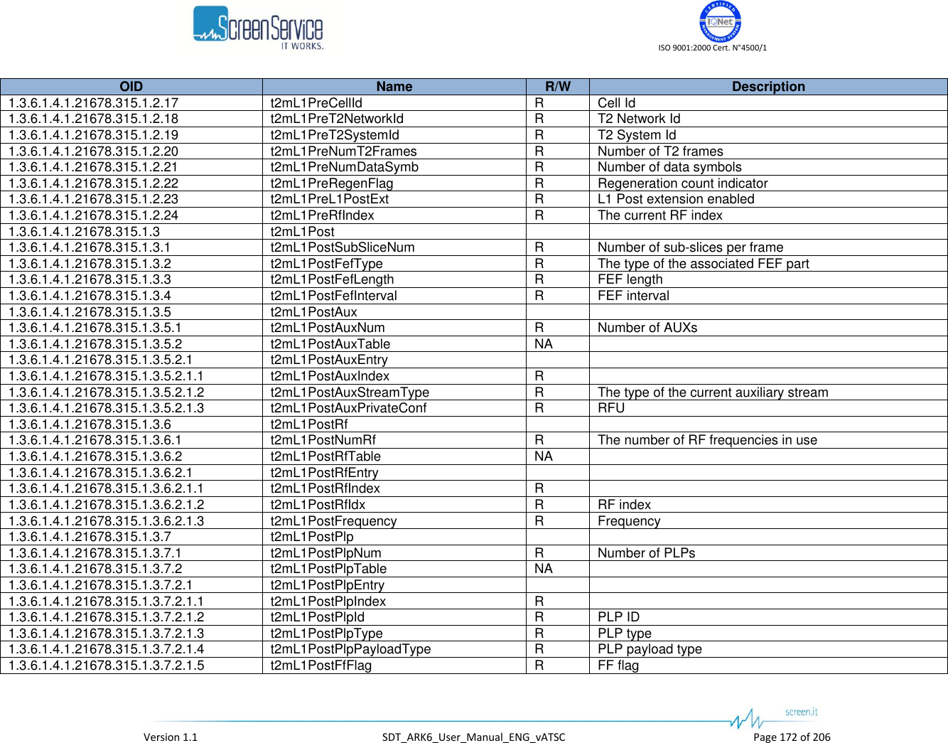
![ISO 9001:2000 Cert. N°4500/1 Version 1.1 SDT_ARK6_User_Manual_ENG_vATSC Page 173 of 206 OID Name R/W Description 1.3.6.1.4.1.21678.315.1.3.7.2.1.6 t2mL1PostFirstRfIdx R First RF index 1.3.6.1.4.1.21678.315.1.3.7.2.1.7 t2mL1PostFirstFrameIdx R First frame index 1.3.6.1.4.1.21678.315.1.3.7.2.1.8 t2mL1PostGroupId R PLP group id 1.3.6.1.4.1.21678.315.1.3.7.2.1.9 t2mL1PostPlpCod R The code rate used by the associated PLP 1.3.6.1.4.1.21678.315.1.3.7.2.1.10 t2mL1PostPlpMod R The modulation used by the associated PLP 1.3.6.1.4.1.21678.315.1.3.7.2.1.11 t2mL1PostPlpRotation R DVBT2 rotated constellation indicator 1.3.6.1.4.1.21678.315.1.3.7.2.1.12 t2mL1PostPlpFec R The FEC type used by the associated PLP 1.3.6.1.4.1.21678.315.1.3.7.2.1.13 t2mL1PostNumBlocksMax R Maximum number of PLP blocks 1.3.6.1.4.1.21678.315.1.3.7.2.1.14 t2mL1PostFrameInterval R Frame interval 1.3.6.1.4.1.21678.315.1.3.7.2.1.15 t2mL1PostTimeIntLength R Time interleaving length 1.3.6.1.4.1.21678.315.1.3.7.2.1.16 t2mL1PostTimeIntType R Time interleaving type 1.3.6.1.4.1.21678.315.1.3.7.2.1.17 t2mL1PostInbandA R In-band A flag 1.3.6.1.4.1.21678.315.1.3.7.2.1.18 t2mL1PostInbandB R In-band B flag 1.3.6.1.4.1.21678.315.1.3.7.2.1.19 t2mL1PostPlpMode R PLP mode 1.3.6.1.4.1.21678.315.1.3.7.2.1.20 t2mL1PostStaticFlag R Static flag 1.3.6.1.4.1.21678.315.1.3.7.2.1.21 t2mL1PostStaticPaddFlag R Static padding flag 1.3.6.1.4.1.21678.315.2 tMeasure 1.3.6.1.4.1.21678.315.2.1 tmStatistics 1.3.6.1.4.1.21678.315.2.1.1 tmsRxLevel R Output RX level 127: over input -128: low power -63...62: power expressed in dB 1.3.6.1.4.1.21678.315.2.1.2 tmsCarrierOffset R Output carrier offset 1.3.6.1.4.1.21678.315.2.1.3 tmsIfAgc R Output IF AGC level 1.3.6.1.4.1.21678.315.2.1.4 tmsRfAgc R Output RF AGC level 1.3.6.1.4.1.21678.315.2.1.5 tmsTsLock R Demodulated TS Lock 1.3.6.1.4.1.21678.315.2.1.6 tmsSyncStat R Sync statistics 1.3.6.1.4.1.21678.315.2.1.7 tmsMer R Output MER [dBx1e3] 1.3.6.1.4.1.21678.315.2.1.8 tmsSnr R Output SNR [dBx1e3] 1.3.6.1.4.1.21678.315.2.1.9 tmsPreVitBer R Output Pre LDPC BER [1e7] 1.3.6.1.4.1.21678.315.2.1.10 tmsPreRsBer R Output Post BCH FER [1e6] 1.3.6.1.4.1.21678.315.2.1.11 tmsRsErrCount R Output Pre BCH BER [1e9] 1.3.6.1.4.1.21678.315.2.1.12 tmsDemodPpm R Demodulated PPM [ppmx1e2] 1.3.6.1.4.1.21678.315.2.1.13 tmsSignalQuality R Signal quality [%] 1.3.6.1.4.1.21678.315.2.2 tmDemodParams 1.3.6.1.4.1.21678.315.2.2.1 tmdpConstellation R Constellation for current modulation scheme 1.3.6.1.4.1.21678.315.2.2.2 tmdpHierMode R Hierarchy information for current modulation scheme 1.3.6.1.4.1.21678.315.2.2.3 tmdpHpCodeRate R High Priority Code Rate](https://usermanual.wiki/Screen-Service-Broadcasting-Technologies/SDT201UB-ARK6/User-Guide-1671826-Page-173.png)
![ISO 9001:2000 Cert. N°4500/1 Version 1.1 SDT_ARK6_User_Manual_ENG_vATSC Page 174 of 206 OID Name R/W Description 1.3.6.1.4.1.21678.315.2.2.4 tmdpLpCodeRate R Low Priority Code Rate 1.3.6.1.4.1.21678.315.2.2.5 tmdpFft R FFT size 1.3.6.1.4.1.21678.315.2.2.6 tmdpGuardInterval R Guard interval 1.3.6.1.4.1.21678.315.2.2.7 tmdpCelllId R Cell identifier 1.3.6.1.4.1.21678.315.3 isdbtMeasure 1.3.6.1.4.1.21678.315.3.1 imStatistics 1.3.6.1.4.1.21678.315.3.1.1 imsMonTxLevel R Output TX level monitor 127: over input -128: low power -63...62: power expressed in dB 1.3.6.1.4.1.21678.315.3.1.2 imsIfLevel R Measured IF level 1.3.6.1.4.1.21678.315.3.1.3 imsIfAgcDac R Measured IF AGC output DAC value 1.3.6.1.4.1.21678.315.3.1.4 imsDemState R The state of the Meausure board sequencer 1.3.6.1.4.1.21678.315.3.1.5 imsMode R Mode 1.3.6.1.4.1.21678.315.3.1.6 imsGuardInterval R Guard interval 1.3.6.1.4.1.21678.315.3.1.7 imsSTRFreqErr R Frequency error detected by symbol timing recovery [Hz] 1.3.6.1.4.1.21678.315.3.1.8 imsCRFreqErr R Frequency error detected by carrier recovery [kHz] 1.3.6.1.4.1.21678.315.3.1.9 imsCN R Estimated Carrier to Noise ratio (dB x 10) 1.3.6.1.4.1.21678.315.3.2 imLayerStatistics 1.3.6.1.4.1.21678.315.3.2.1 imlsNumber R The number of Layers 1.3.6.1.4.1.21678.315.3.2.2 imlsTable NA 1.3.6.1.4.1.21678.315.3.2.2.1 imlsEntry 1.3.6.1.4.1.21678.315.3.2.2.1.1 imlsIndex R 1.3.6.1.4.1.21678.315.3.2.2.1.2 imlsDescr R Layer description 1.3.6.1.4.1.21678.315.3.2.2.1.3 imlsMod R Modulation scheme 1.3.6.1.4.1.21678.315.3.2.2.1.4 imlsCodeRate R Code rate 1.3.6.1.4.1.21678.315.3.2.2.1.5 imlsTILength R Time Interleaving length 1.3.6.1.4.1.21678.315.3.2.2.1.6 imlsSegNum R Number of segments 1.3.6.1.4.1.21678.315.3.2.2.1.7 imlsMer R MER [dB] (* 10) 1.3.6.1.4.1.21678.315.3.2.2.1.8 imlsPreVitBer R Pre-Viterbi BER (* 10^9) 1.3.6.1.4.1.21678.315.3.2.2.1.9 imlsPostVitBer R Post-Viterbi BER (* 10^9) 1.3.6.1.4.1.21678.315.3.2.2.1.10 imlsPktErrRate R Packet Error Rate (* 10^9) 1.3.6.1.4.1.21678.315.4 atscMeasure 1.3.6.1.4.1.21678.315.4.1 amStatistics 1.3.6.1.4.1.21678.315.4.1.1 amsFrequencyOffset R Output carrier offset 1.3.6.1.4.1.21678.315.4.1.2 amsDemodStatus R VSB demodulation status 1.3.6.1.4.1.21678.315.4.1.3 amsEqStatus R Equalizer status 1.3.6.1.4.1.21678.315.4.1.4 amsDemLock R Demodulator lock status](https://usermanual.wiki/Screen-Service-Broadcasting-Technologies/SDT201UB-ARK6/User-Guide-1671826-Page-174.png)
![ISO 9001:2000 Cert. N°4500/1 Version 1.1 SDT_ARK6_User_Manual_ENG_vATSC Page 175 of 206 OID Name R/W Description 1.3.6.1.4.1.21678.315.4.1.5 amsAgcLock R Digital AGC lock status 1.3.6.1.4.1.21678.315.4.1.6 amsFrameLock R Frame lock status 1.3.6.1.4.1.21678.315.4.1.7 amsCarrierFreqLoopLock R Carrier frequency loop lock status 1.3.6.1.4.1.21678.315.4.1.8 amsTimingFreqLoopLock R Timing frequency loop lock status 1.3.6.1.4.1.21678.315.4.1.9 amsSnr R Signal to Noise Ratio [dB] 1.3.6.1.4.1.21678.315.4.1.10 amsSer R Segment Error Rate 1.3.6.1.4.1.21678.315.4.1.11 amsBer R Bit Error Rate 1.3.6.1.4.1.21678.317 ssbtCommon 1.3.6.1.4.1.21678.317.1 info 1.3.6.1.4.1.21678.317.1.1 infoName RW The station identifier 1.3.6.1.4.1.21678.317.1.2 infoManufacturer R Manufacturer name 1.3.6.1.4.1.21678.317.1.3 infoVersion 1.3.6.1.4.1.21678.317.1.3.1 versionNumber R Number of software versions 1.3.6.1.4.1.21678.317.1.3.2 versionTable NA 1.3.6.1.4.1.21678.317.1.3.2.1 versionEntry 1.3.6.1.4.1.21678.317.1.3.2.1.1 versionIndex R Software version index 1.3.6.1.4.1.21678.317.1.3.2.1.2 versionDescr R Software description 1.3.6.1.4.1.21678.317.1.3.2.1.3 versionVersion R Software version 1.3.6.1.4.1.21678.317.1.4 infoHw 1.3.6.1.4.1.21678.317.1.4.1 hwNumber R Number of devices 1.3.6.1.4.1.21678.317.1.4.2 hwTable NA 1.3.6.1.4.1.21678.317.1.4.2.1 hwEntry 1.3.6.1.4.1.21678.317.1.4.2.1.1 hwIndex R Device index 1.3.6.1.4.1.21678.317.1.4.2.1.2 hwDescr R Device description 1.3.6.1.4.1.21678.317.1.4.2.1.3 hwSerialNumber R Serial number 1.3.6.1.4.1.21678.317.1.4.2.1.4 hwUniqueId R Unique device ID 1.3.6.1.4.1.21678.317.2 settings 1.3.6.1.4.1.21678.317.2.1 sDate RW Device date and time as specified in SNMPv2-TC 1.3.6.1.4.1.21678.317.2.2 sSystem 1.3.6.1.4.1.21678.317.2.2.1 ssLoadConfig W Load configuration 1.3.6.1.4.1.21678.317.2.2.2 ssSaveConfig W Save configuration 1.3.6.1.4.1.21678.317.2.2.3 ssReset W Reset board 1.3.6.1.4.1.21678.317.3 events 1.3.6.1.4.1.21678.317.3.1 evNumber R The total number of alarms 1.3.6.1.4.1.21678.317.3.2 evOverwritten R The events list has been overwritten. Obsolete events began to be overwritten."](https://usermanual.wiki/Screen-Service-Broadcasting-Technologies/SDT201UB-ARK6/User-Guide-1671826-Page-175.png)
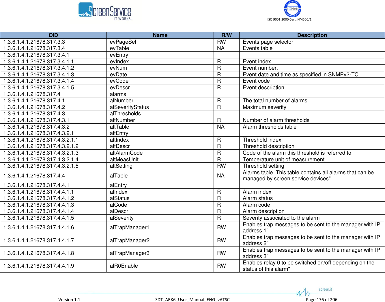
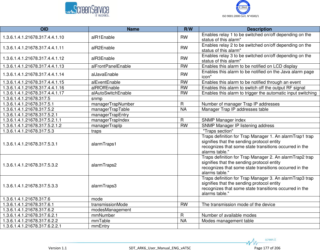
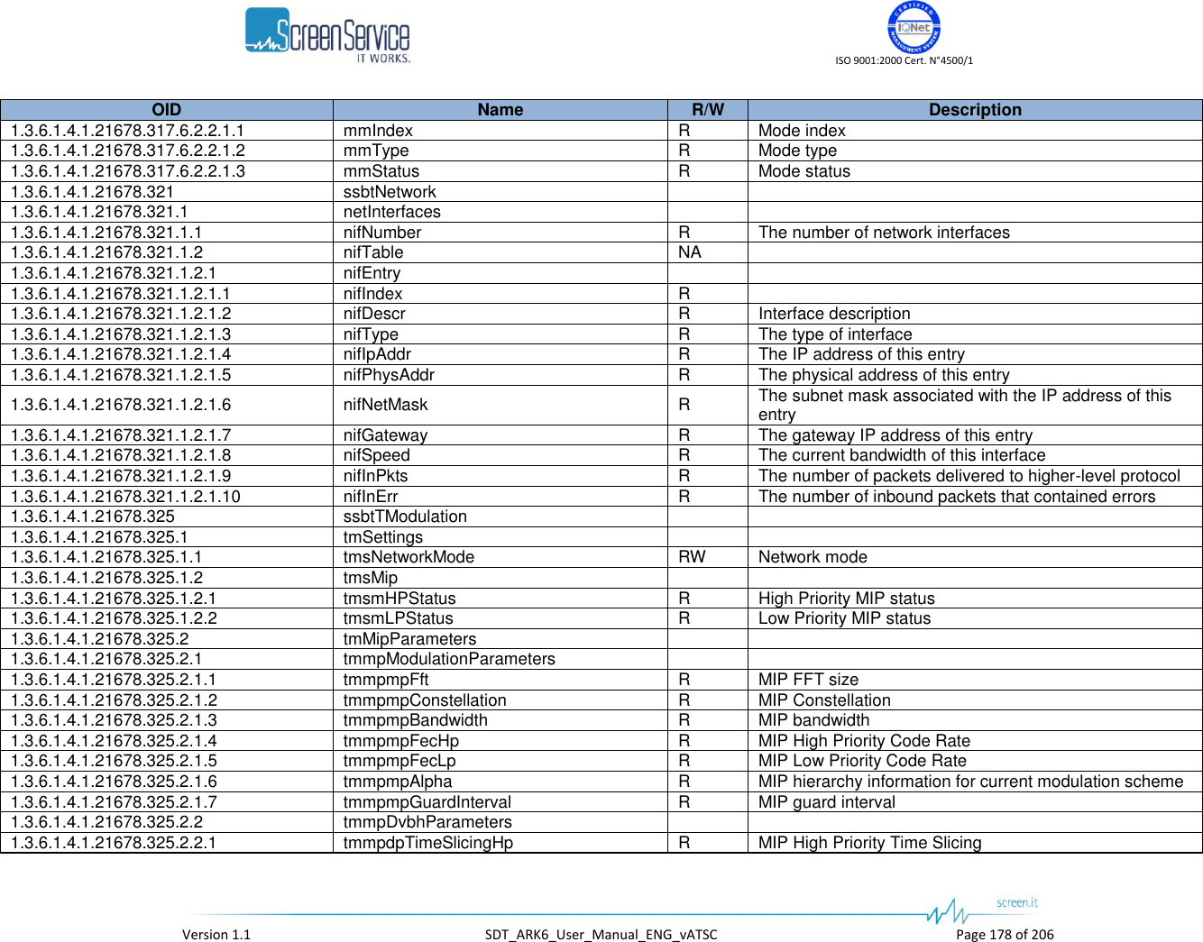
![ISO 9001:2000 Cert. N°4500/1 Version 1.1 SDT_ARK6_User_Manual_ENG_vATSC Page 179 of 206 OID Name R/W Description 1.3.6.1.4.1.21678.325.2.2.2 tmmpdpTimeSlicingLp R MIP Low Priority Time Slicing 1.3.6.1.4.1.21678.325.2.2.3 tmmpdpMpeFecHp R High Priority MPE-FEC 1.3.6.1.4.1.21678.325.2.2.4 tmmpdpMpeFecLp R Low Priority MPE-FEC 1.3.6.1.4.1.21678.325.2.2.5 tmmpdpInterleaver R MIP native/in-depth symbol interleaver selector 1.3.6.1.4.1.21678.325.2.3 tmmpMipFunctions 1.3.6.1.4.1.21678.325.2.3.1 tmmpmfTxId 1.3.6.1.4.1.21678.325.2.3.1.1 tmmpmftiNumber RW Transmitter identifier 1.3.6.1.4.1.21678.325.2.3.1.2 tmmpmftiEnableTxId0 RW Enables the TX ID 0 1.3.6.1.4.1.21678.325.2.3.2 tmmpmfCellId 1.3.6.1.4.1.21678.325.2.3.2.1 tmmpmfciEnable RW Enables the Cell ID function 1.3.6.1.4.1.21678.325.2.3.2.2 tmmpmfciFunctionEnable R Enable function status 1.3.6.1.4.1.21678.325.2.3.2.3 tmmpmfciFunctionTag R Cell id function tag detection status 1.3.6.1.4.1.21678.325.2.3.2.4 tmmpmfciStatus R Cell id function 1.3.6.1.4.1.21678.325.2.3.2.5 tmmpmfciWaitForEnable R Cell id function wait for enable status 1.3.6.1.4.1.21678.325.2.3.3 tmmpmfMaxDelay R MIP maximum delay [100ns] 1.3.6.1.4.1.21678.325.2.3.4 tmmpmfFrequencyOffset 1.3.6.1.4.1.21678.325.2.3.4.1 tmmpmffoEnable RW Enables the MIP frequency offset function 1.3.6.1.4.1.21678.325.2.3.4.2 tmmpmffoStatus R MIP frequency offset function [Hz] 1.3.6.1.4.1.21678.325.2.3.5 tmmpmfTimeOffset 1.3.6.1.4.1.21678.325.2.3.5.1 tmmpmftoEnable RW Enables the MIP time offset function 1.3.6.1.4.1.21678.325.2.3.5.2 tmmpmftoStatus R MIP time offset function [100ns] 1.3.6.1.4.1.21678.325.3 tmLocalParameters 1.3.6.1.4.1.21678.325.3.1 tmlpModulationParameters 1.3.6.1.4.1.21678.325.3.1.1 tmlpmpFft RW FFT size 1.3.6.1.4.1.21678.325.3.1.2 tmlpmpConstellation RW Constellation 1.3.6.1.4.1.21678.325.3.1.3 tmlpmpFecHp RW High Priority Code Rate 1.3.6.1.4.1.21678.325.3.1.4 tmlpmpFecLP RW Low Priority Code Rate 1.3.6.1.4.1.21678.325.3.1.5 tmlpmpAlpha RW Hierarchy information for current modulation scheme 1.3.6.1.4.1.21678.325.3.1.6 tmlpmpGuardInterval RW Guard interval 1.3.6.1.4.1.21678.325.3.2 tmlpDvbhParameters 1.3.6.1.4.1.21678.325.3.2.1 tmlpdpTimeSlicingHp RW Enables the High Priority Time Slicing 1.3.6.1.4.1.21678.325.3.2.2 tmlpdpTimeSlicingLp RW Enables the Low Priority Time Slicing 1.3.6.1.4.1.21678.325.3.2.3 tmlpdpMpeFecHp RW Enables the High Priority MPE-FEC 1.3.6.1.4.1.21678.325.3.2.4 tmlpdpMpeFecLp RW Enables the Low Priority MPE-FEC 1.3.6.1.4.1.21678.325.3.2.5 tmlpdpInterleaver RW Symbol interleaver selector 1.3.6.1.4.1.21678.325.3.3 tmlpMipFunctions](https://usermanual.wiki/Screen-Service-Broadcasting-Technologies/SDT201UB-ARK6/User-Guide-1671826-Page-179.png)
![ISO 9001:2000 Cert. N°4500/1 Version 1.1 SDT_ARK6_User_Manual_ENG_vATSC Page 180 of 206 OID Name R/W Description 1.3.6.1.4.1.21678.325.3.3.1 tmlpmfCellIdEnable RW Enables the use of the locally set Cell ID 1.3.6.1.4.1.21678.325.3.3.2 tmlpmfCellId RW Local cell id setting 1.3.6.1.4.1.21678.325.3.3.3 tmlpmflDelay RW User delay setting 100ns] 1.3.6.1.4.1.21678.325.3.3.4 tmlpmfFrequencyOffset RW Frequency offset setting [Hz] 1.3.6.1.4.1.21678.325.3.3.5 tmlpmfTimeOffset RW Time offset setting [100ns] 1.3.6.1.4.1.21678.325.4 tmCurrentParameters 1.3.6.1.4.1.21678.325.4.1 tmcpModulationParameters 1.3.6.1.4.1.21678.325.4.1.1 tmcpmpFft R Used transmission mode 1.3.6.1.4.1.21678.325.4.1.2 tmcpmpConstellation R Used constellation 1.3.6.1.4.1.21678.325.4.1.3 tmcpmpBandwidth R Used bandwidth 1.3.6.1.4.1.21678.325.4.1.4 tmcpmpFecHp R Used High Priority Code Rate 1.3.6.1.4.1.21678.325.4.1.5 tmcpmpFecLp R Used Low Priority Code Rate 1.3.6.1.4.1.21678.325.4.1.6 tmcpmpAlpha R Used hierarchical mode 1.3.6.1.4.1.21678.325.4.1.7 tmcpmpGuardInterval R Used guard interval 1.3.6.1.4.1.21678.325.4.2 tmcpDvbhParameters 1.3.6.1.4.1.21678.325.4.2.1 tmcpdpTimeSlicingHp R Used High Priority Time Slicing 1.3.6.1.4.1.21678.325.4.2.2 tmcpdpTimeSlicingLp R Used Low Priority Time Slicing 1.3.6.1.4.1.21678.325.4.2.3 tmcpdpMpeFecHp R Used High Priority MPE-FEC 1.3.6.1.4.1.21678.325.4.2.4 tmcpdpMpeFecLp R Used Low Priority MPE-FEC 1.3.6.1.4.1.21678.325.4.2.5 tmcpdpInterleaver R Used symbol interleaver 1.3.6.1.4.1.21678.325.4.3 tmcpsMipFunctions 1.3.6.1.4.1.21678.325.4.3.1 tmcpmfCellId R Used Cell ID 1.3.6.1.4.1.21678.325.4.3.2 tmcpmfSystemDelay R System delay indicator [100ns] 1.3.6.1.4.1.21678.325.4.3.3 tmcpmfFrequencyOffset R Used frequency offset 1.3.6.1.4.1.21678.325.4.3.4 tmcpmfTimeOffset R Used time offset [100ns] 1.3.6.1.4.1.21678.325.4.3.5 tmcpmfCentreFrequency R Centre frequency indicator (expressed in Hz) 1.3.6.1.4.1.21678.325.4.3.6 tmcpmfNetworkDelay R Network delay [100ns] indicator 1.3.6.1.4.1.21678.325.4.3.7 tmcpmfDeviceDelay R Shows the device delay [100ns]](https://usermanual.wiki/Screen-Service-Broadcasting-Technologies/SDT201UB-ARK6/User-Guide-1671826-Page-180.png)
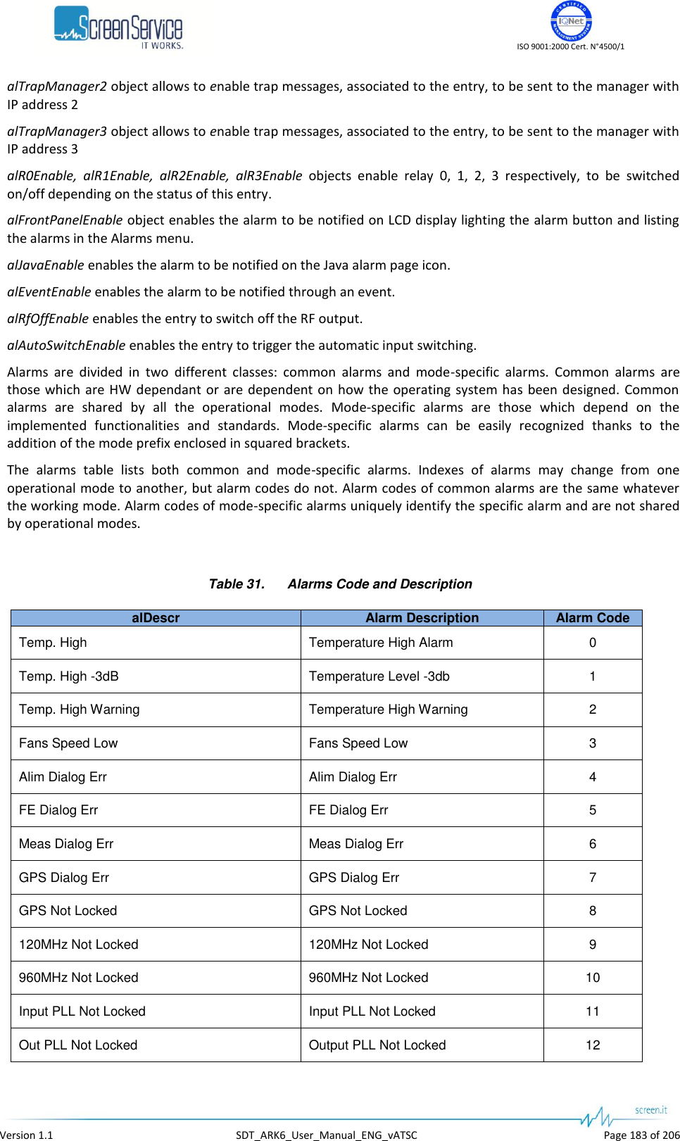
![ISO 9001:2000 Cert. N°4500/1 Version 1.1 SDT_ARK6_User_Manual_ENG_vATSC Page 184 of 206 alDescr Alarm Description Alarm Code 10MHz Not Locked 10MHz Not Locked 13 1PPS Not Locked 1 PPS Not Locked 14 FPGA Boot Err FPGA Boot Error 15 FWD Power High Forward Power High 16 FWD Pwr Low Warning Forward Power Low Warning 17 FWD Pwr Low Forward Power Low Alarm 18 Reflex Power High Reflex Power High 19 File System Err File System Error 20 File Err Bad File In File System 21 PS1 V Out Of Range PS Voltage Out Of Range 22 PS1 I Out Of Range PS Current Out Of Range 23 CPU Fan Err CPU Fan Error 24 Test Mode Test Mode 25 FE S2 Not Locked FE S2 not locked 26 FE S2 S/N Low FE S2 SNR Low 27 FE S2 BER High FE S2 BER high 28 [ATSC] No Input [ATSC] Input not valid 1056 [ATSC] Input Overflow [ATSC] Input overflow 1057 [ATSC] MH Err [ATSC] MH Error 1058 [ATSC] MEAS Demodulator Not Locked [ATSC] Meas Not Locked 1059 [ATSC] MEAS SNR Low [ATSC] Meas SNR Low 1060 [ATSC] FE Demodulator Not Locked [ATSC] FE Not Locked 1061 [ATSC] FE SNR Low [ATSC] FE SNR Low 1062 [ATSC] TVCT Not Present [ATSC] No TVCT 1063](https://usermanual.wiki/Screen-Service-Broadcasting-Technologies/SDT201UB-ARK6/User-Guide-1671826-Page-184.png)
![ISO 9001:2000 Cert. N°4500/1 Version 1.1 SDT_ARK6_User_Manual_ENG_vATSC Page 186 of 206 Table 32. Alarm Thresholds Description altDescr Threshold Description Alarm Code Temp. High -3dB Temperature warning threshold expressed in °C. 1 Temp. High Warning Temperature alarm threshold expressed in °C. 2 FWD Pwr Low Warning Forward power warning threshold expressed in dB. 17 FWD Pwr Low Forward power alarm threshold expressed in dB. 18 FE Squelch [DVB-T2] FE Squelch alarm threshold expressed in dB. 1315 FE Pre LDPC BER [DVB-T2] FE Pre LDPC BER alarm threshold expressed in dB*1e7. 1316 FE SNR Low [DVB-T2] FE Signal to Noise alarm threshold expressed in dB*1e3. 1317 FE MER Low [DVB-T2] FE MER alarm threshold expressed in dB*1e3. 1318 FE S.Quality Low [DVB-T2] FE Signal Quality alarm threshold. 1319 Meas Pre LDPC BER [DVB-T2] Measure Pre LDPC BER alarm threshold expressed in dB*1e7. 1321 Meas SNR Low [DVB-T2] Measure Signal to Noise alarm threshold expressed in dB*1e3. 1322 Meas MER Low [DVB-T2] Measure MER alarm threshold expressed in dB*1e3. 1323 Meas S.Quality Low [DVB-T2] Measure Signal Quality alarm threshold. 1324 FE LDPC Mean Err [DVB-T2] FE LDPC Mean Error alarm threshold 1330 MEAS LDPC Mean Err [DVB-T2] Measure LDPC Mean Error alarm threshold 1331 FE Squelch [DVB-T] FE Squelch alarm threshold. 809 FE Pre Viterbi BER [DVB-T] FE PreViterbi BER High alarm threshold (expressed in dB*1e7). 810 FE SNR Low [DVB-T] FE SNR Low alarm threshold (expressed in dB*1e3). 811 FE MER Low [DVB-T] FE MER Low alarm threshold (expressed in dB*1e3). 812 FE S.Quality Low [DVB-T] FE Signal Quality Low alarm threshold. 813 Meas Pre Viterbi BER [DVB-T] MEAS PreViterbi BER High alarm threshold (expressed in dB*1e7). 815 Meas SNR Low [DVB-T] MEAS SNR Low alarm threshold (expressed in dB*1e3). 816 Meas MER Low [DVB-T] MEAS MER Low alarm threshold (expressed in dB*1e3). 817](https://usermanual.wiki/Screen-Service-Broadcasting-Technologies/SDT201UB-ARK6/User-Guide-1671826-Page-186.png)
![ISO 9001:2000 Cert. N°4500/1 Version 1.1 SDT_ARK6_User_Manual_ENG_vATSC Page 187 of 206 altDescr Threshold Description Alarm Code Meas S.Quality Low [DVB-T] MEAS Signal Quality Low alarm threshold. 818 FE SNR Low [ATSC] FE SNR Low alarm threshold (expressed in dB*1e3). 1062 Meas SNR Low [ATSC] MEAS SNR Low alarm threshold (expressed in dB*1e3). 1060](https://usermanual.wiki/Screen-Service-Broadcasting-Technologies/SDT201UB-ARK6/User-Guide-1671826-Page-187.png)
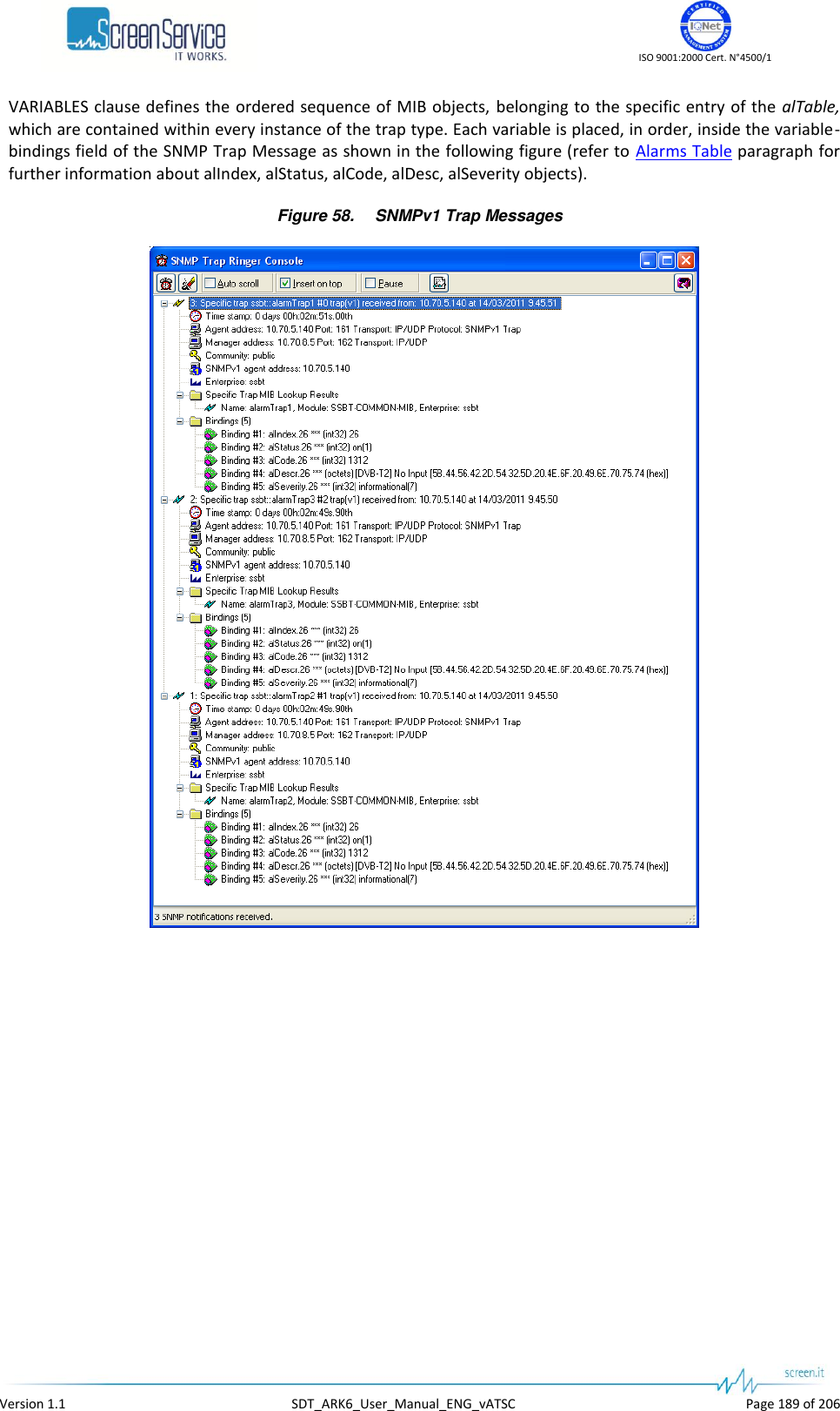
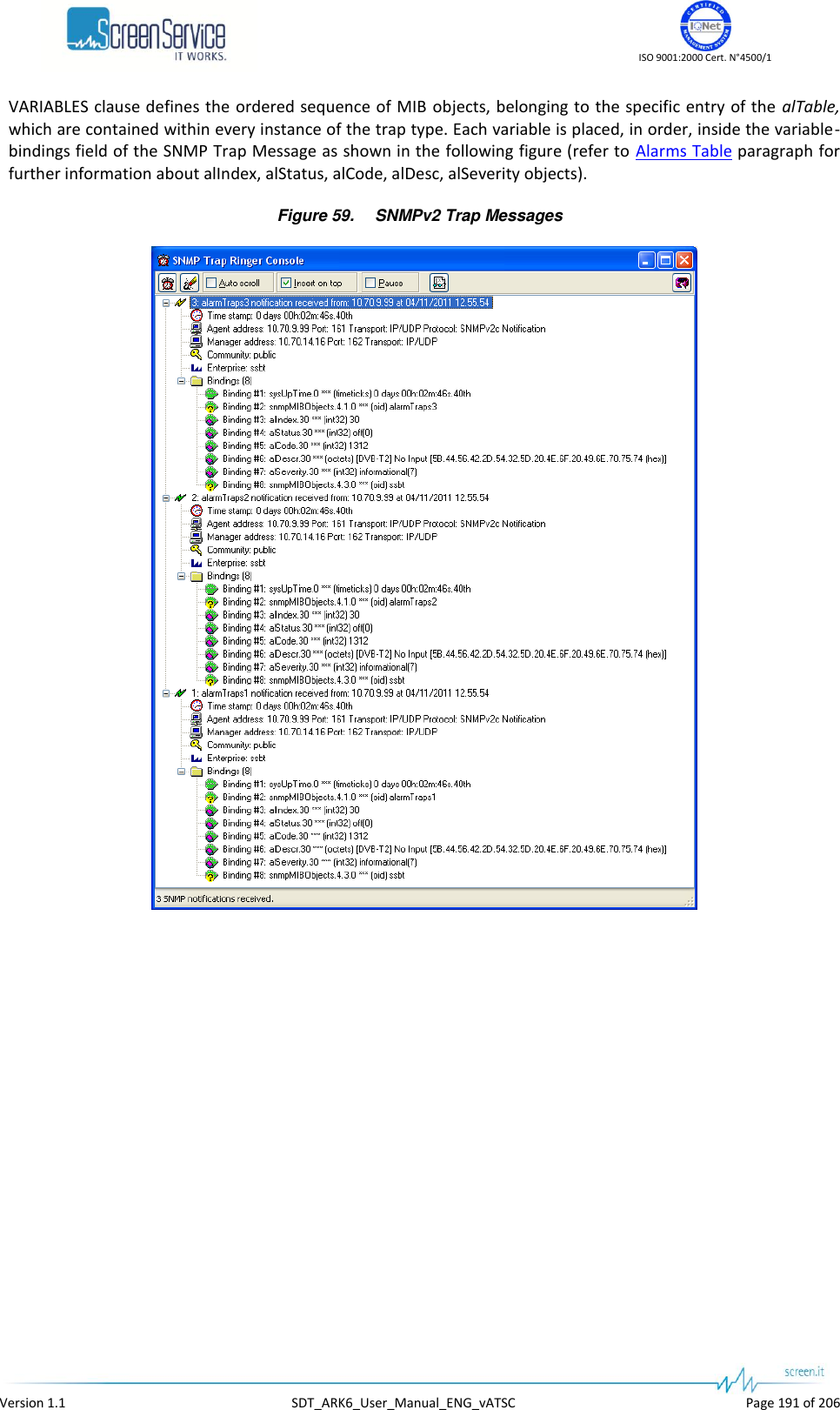
![ISO 9001:2000 Cert. N°4500/1 Version 1.1 SDT_ARK6_User_Manual_ENG_vATSC Page 194 of 206 Input switching rules can be selected in the Alarms page through the SWITCH alarm mask and depend on the transmission standard. Here below the available rules for each operative mode: ITU [ITU] No Video Input [ITU] Input wrong standard ATSC [ATSC] No Input: input Transport Stream not locked [ATSC] Input Overflow: input TS overflow [ATSC] MH Err [ATSC] FE Demodulator Not Locked: input RF signal not locked [ATSC] FE SNR Low: RF input SNR under the alarm threshold [ATSC] No TVCT: TVCT table not present in the selected input stream](https://usermanual.wiki/Screen-Service-Broadcasting-Technologies/SDT201UB-ARK6/User-Guide-1671826-Page-194.png)