Screen Service Broadcasting Technologies SDTX-ARK6 20 Watt Multimode SDR Transmitter User Manual Software
Screen Service Broadcasting Technologies SpA 20 Watt Multimode SDR Transmitter Software
User Manual

ISO 9001:2000
Cert. N°4500/1
Document name: SDT_ARK6_User_Manual_ENG_vATSC
Document code: ARK6-UM-000
Author: C. Di Biase
Date: September 23rd, 2011
Version: 1.1
Software User Manual
ARK6
External Document

ISO 9001:2000 Cert. N°4500/1
Version 1.1 SDT_ARK6_User_Manual_ENG_vATSC Page 2 of 206
Table of Contents
1 Document structure ............................................................................................................... 5
2 Scope of the document .......................................................................................................... 6
3 Introduction ........................................................................................................................... 7
3.1 Digitizer features .............................................................................................................. 9
3.2 Satellite receivers features ............................................................................................... 9
3.2.1 DVB-S/S2 .................................................................................................................. 9
3.2.2 DVB-S/S2 plus CAM ............................................................................................... 10
3.3 Terrestrial receivers features ......................................................................................... 11
3.3.1 ATSC ....................................................................................................................... 11
3.4 ITU Transmitter features ................................................................................................ 12
3.4.1 ITU Features........................................................................................................... 12
3.4.2 ITU Signal Processing ............................................................................................. 13
3.5 ATSC Transmitter features ............................................................................................. 14
3.5.1 ATSC Features ........................................................................................................ 14
3.5.2 ATSC Signal Processing .......................................................................................... 14
3.6 System Features ............................................................................................................. 15
3.7 Synchronization .............................................................................................................. 15
4 Specifications ....................................................................................................................... 16
4.1 Input Interfaces .............................................................................................................. 16
4.2 Output Interfaces ........................................................................................................... 19
4.3 Control Interfaces ........................................................................................................... 22
4.3.1 RS232 pinout ......................................................................................................... 23
4.3.2 TLC pinout .............................................................................................................. 23
4.3.3 TLS pinout .............................................................................................................. 24
4.4 Power Supply .................................................................................................................. 25
4.5 Environmental Specification .......................................................................................... 27
4.6 Mechanical Specification................................................................................................ 27
5 Java Graphic User Interface ................................................................................................. 28
5.1 Authentication Option ................................................................................................... 28
5.2 Java Menu Bar ................................................................................................................ 29
5.3 Home Page ..................................................................................................................... 31
5.4 Input ............................................................................................................................... 32
5.5 Front-End ........................................................................................................................ 37
5.5.1 Tuner window: RF power level monitor ................................................................ 38

ISO 9001:2000 Cert. N°4500/1
Version 1.1 SDT_ARK6_User_Manual_ENG_vATSC Page 3 of 206
5.5.2 DIGITIZER FE Type .................................................................................................. 39
5.5.3 ATSC FE Type ......................................................................................................... 41
5.6 ATSC ............................................................................................................................... 44
5.6.1 ATSC Settings ......................................................................................................... 45
5.6.2 ATSC Modulation ................................................................................................... 49
5.6.3 ATSC TVCT .............................................................................................................. 51
5.6.4 ATSC Measure ........................................................................................................ 52
5.7 ITU.470 ........................................................................................................................... 54
5.7.1 ITU Settings ............................................................................................................ 55
5.7.2 ITU Modulation ...................................................................................................... 59
5.8 Manual compensation ................................................................................................... 66
5.8.1 Linear Precorrection .............................................................................................. 66
5.8.2 Non Linear Precorrection ...................................................................................... 68
5.8.3 Port 5000 connection ............................................................................................ 69
5.9 Adaptive compensation ................................................................................................. 70
5.9.1 Linear Adaptive Precorrection ............................................................................... 70
5.9.2 Adaptive Non-Linear Precorrection ....................................................................... 74
5.10 Output ............................................................................................................................ 76
5.10.1 Reflex Power Management ................................................................................... 85
5.11 Network .......................................................................................................................... 87
5.12 GPS ................................................................................................................................. 92
5.12.1 Holdover Management ......................................................................................... 94
5.13 Alarms ............................................................................................................................ 99
5.14 Events ........................................................................................................................... 116
5.14.1 Date and Time Setting ......................................................................................... 126
5.14.2 Task Error Event ................................................................................................... 126
5.14.3 System Error Event .............................................................................................. 127
5.14.4 System Initialization Event .................................................................................. 128
5.15 System menu ................................................................................................................ 131
5.15.1 File Menu ............................................................................................................. 131
5.15.2 View Menu........................................................................................................... 132
5.15.3 Help Menu ........................................................................................................... 135
5.16 Download Software Standalone................................................................................... 137
6 Local User Interface ........................................................................................................... 138
6.1 Boot and Welcome Message ....................................................................................... 139

ISO 9001:2000 Cert. N°4500/1
Version 1.1 SDT_ARK6_User_Manual_ENG_vATSC Page 4 of 206
6.2 Idle Menu ..................................................................................................................... 140
6.3 Main Menu ................................................................................................................... 141
6.4 LCD Alarms ................................................................................................................... 142
7 SNMP – Simple Network Management Protocol ............................................................... 144
7.1 SNMP Protocol Preferences ......................................................................................... 145
7.2 Monitoring ................................................................................................................... 146
7.3 Events Monitoring ........................................................................................................ 181
7.4 Configuring alarm masks and alarm thresholds ........................................................... 182
7.4.1 Alarms Table ........................................................................................................ 182
7.4.2 Thresholds Table.................................................................................................. 185
7.5 Traps ............................................................................................................................. 188
7.5.1 SNMPv1 ............................................................................................................... 188
7.5.2 SNMPv2 ............................................................................................................... 190
7.5.3 Configuring traps ................................................................................................. 192
Appendix A. Automatic input source selection methods ........................................................ 193
A.1 Input Autoswitch .......................................................................................................... 193
A.2 Seamless input switching ............................................................................................. 196
Appendix B. Java Virtual Machine ........................................................................................... 197
B.1 Ethernet connection ..................................................................................................... 197
B.1.1 Configuration ....................................................................................................... 197
B.2 Java(TM) Platform ........................................................................................................ 197
B.2.1 Download ............................................................................................................ 197
B.2.2 Java Control Panel ............................................................................................... 197
B.3 Supported Web Browsers ............................................................................................ 197
Appendix C. Application Note .................................................................................................. 198
C.1 How to update.............................................................................................................. 198
Appendix D. Document versions .............................................................................................. 203

ISO 9001:2000 Cert. N°4500/1
Version 1.1 SDT_ARK6_User_Manual_ENG_vATSC Page 5 of 206
1 Document structure
This ARK6 User Manual has the following chapters and appendices:
Chapter 1 – Document structure.
Chapter 2 – Scope of the document.
Chapter 3 – Introduction
This chapter contains an overview of ARK6 and its features.
Chapter 4 – Specifications
This chapter lists the ARK6 specifications.
Chapter 5 – Java remote graphic user interface.
This chapter describes the Java interface provided for board managing.
Chapter 6 – Local user interface.
This chapter describes the local user interface provided for board managing.
Chapter 7 – SNMP - Simple Network Management Protocol
This chapter describes the SNMP interface provided for board managing.
Appendix A – Java Virtual Machine.
Appendix with all instruction needed to manage Java Virtual Machine.
Appendix B – Application Note.
Appendix with all instructions needed to update ARK6 devices.
Appendix C – Document versions.
Appendix with additional information, the present document versions.
Appendix D – List of Tables.
Appendix E – List of Figures.

ISO 9001:2000 Cert. N°4500/1
Version 1.1 SDT_ARK6_User_Manual_ENG_vATSC Page 6 of 206
2 Scope of the document
Purpose of this document is to provide a comprehensive description of the functionalities of the SDT
Series ARK-6 and to provide operating information on the software elements of the ARK6 system.
SDT ARK6 User Manual provides software setup information and includes an overview of Java, SNMP
and Local user interfaces.

ISO 9001:2000 Cert. N°4500/1
Version 1.1 SDT_ARK6_User_Manual_ENG_vATSC Page 7 of 206
3 Introduction
The SDT ARK-6 Series has been designed as a brand new model of software defined transmitters which
incorporate all the technical and functional capabilities of the previous models of the ARK-1 family (ARK-
1, ARK-R, ARK-T, ARK-ATSC, ECHO-2) together with a complete set of new functionalities that bring the
transmitter at the forefront of the technology edge.
The New SDT ARK-6 Series is the result of years of research and represents the state of the art of the
worldwide transmitter technology. We call it UNIVERSAL DRIVER because of its incredible capability to
modulate in all schemes, just uploading a proper software package. It is perfect for both international
broadcasters which have business in several countries to increase manageability of investment through
reduction of transmitter types and national broadcasters, due for its versatility in operation modes and
configuration. In fact it can be used as a Transmitter, an Heterodyne Transposer, a Regenerative
Transposer and Single Frequency Echo Canceller (proper to Single Frequency Networks), all in a single
hardware.
ARK-6 UNIVERSAL DRIVER is resilient to future evolutions of technology and standardization: this
platform guarantees a perfect upgrade path for new modulation schemes that the researchers will
delivery. Besides ARK-6 UNIVERSAL DRIVER already implements DVB-T/T2, PAL, ATSC/MH, NTSC, ISDB-T
modulations. The SDT ARK-6 allows selection of transmission modes in various ways: remotely, using a
dry contact; via SNMP commands; via TCP/IP, using the Web graphic interface; or even via a dedicated
command inserted into the transport stream. Functional interfaces are available for total remote control
of the apparatus by means of serial protocols or TCP/IP ports. Thanks to the internal Web server the
apparatus can be easily monitored and configured and updated using a LAN connection and a standard
Web browser. Moreover, the built-in SNMP agent allows full automated remote control.
Based on Software Defined Technology, ARK-6 allows the definition of different operative modes on the
same hardware platform. A single software controller allows the ARK-6 to be loaded with up to five
working modes simultaneously and to switch between them preserving each mode-specific
configuration.
The SDT ARK-6 Series specifications can be found in chapter 4.
A brief description of the main features and potentialities of each operative mode follows in next
paragraphs.
The following table shows all the allowed hardware configurations.

ISO 9001:2000 Cert. N°4500/1
Version 1.1 SDT_ARK6_User_Manual_ENG_vATSC Page 8 of 206
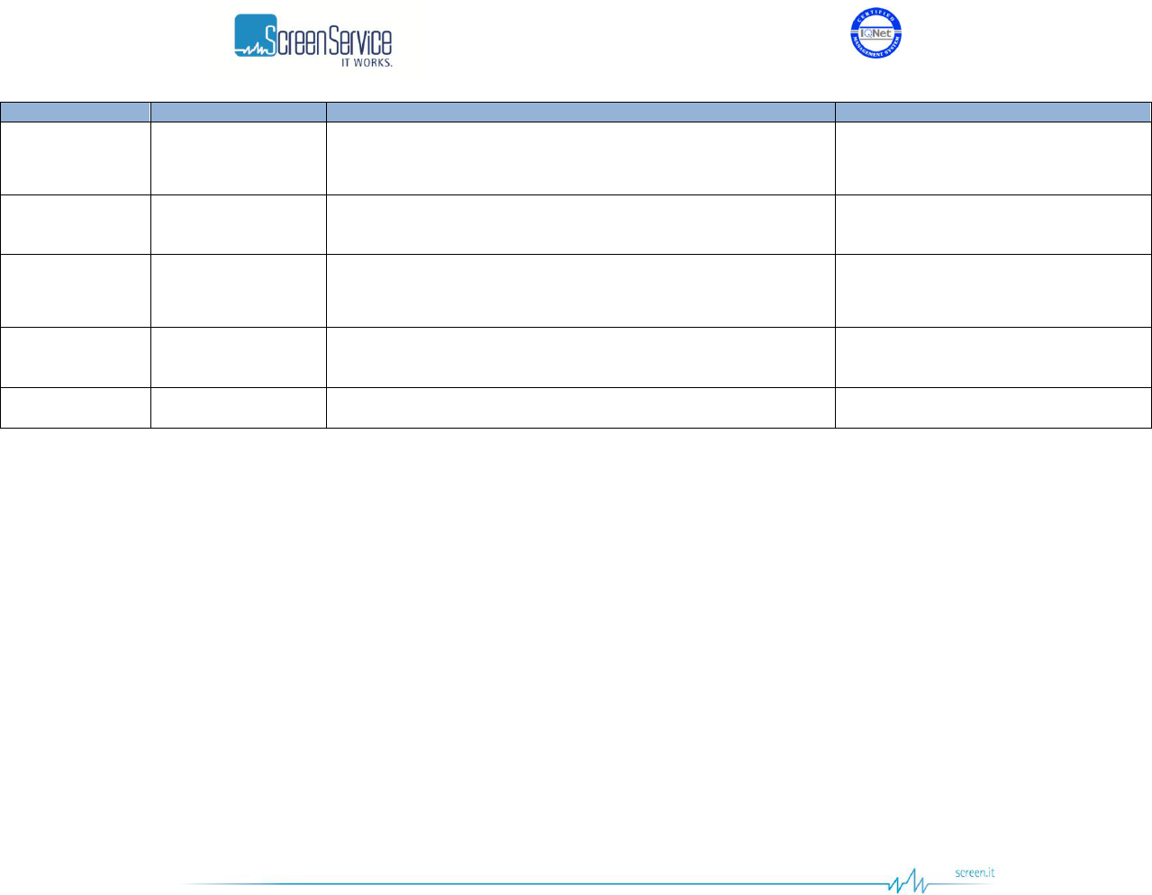
Table 1. Hardware options
Front-End
Modulation
DVB-T/H
DVB-T2
ISDBT
ATSC
ITU
None
Transmitter
Transmitter
Transmitter
Transmitter
Transmitter
DVB-S/S2
Transmitter
with DVB-S/S2 RF input
Transmitter
with DVB-S/S2 RF input
Transmitter
with DVB-S/S2 RF input
Transmitter
with DVB-S/S2 RF input
X
DVB-S/S2 + CAM
Transmitter
with DVB-S/S2 RF input
(with CAM)
Transmitter
with DVB-S/S2 RF input
(with CAM)
Transmitter
with DVB-S/S2 RF input
(with CAM)
Transmitter
with DVB-S/S2 RF input
(with CAM)
Transmitter with decoded
DVBS2 RX input
DVB-T/T2
Regenerative Transposer
Heterodyne Transposer
Echo Canceller
Regenerative Transposer
Heterodyne Transposer
Echo Canceller
X
X
X
ISDBT
X
X
Regenerative Transposer
Heterodyne Transposer
Echo Canceller
X
X
ATSC
X
X
X
Regenerative Transposer
Heterodyne Transposer
Echo Canceller
X
DIGITALIZER
X
X
X
X
Transmitter
with A/V analog inputs

ISO 9001:2000 Cert. N°4500/1
Version 1.1 SDT_ARK6_User_Manual_ENG_vATSC Page 9 of 206
3.1 Digitizer features
Supports the A/D conversion and decoding of NTSC and PAL CVBS inputs
Supports 2 CVBS video and 2 L/R audio inputs
Adaptive 2-D, 5-line, adaptive comb filter
Automatic video standard detection (NTSC/PAL)
Automatic video standard switching
Luma-peaking with programmable gain
3.2 Satellite receivers features
3.2.1 DVB-S/S2
Input DVB-S and DVB-S2 demodulator that conforms to ETSI EN 300 421 and ETSI TR 102 376
respectively.
Dual multi standard demodulation:
Legacy DVBS and DirecTVTM QPSK
DVBS2 QPSK, 8PSK, 16 and 32APSK
Multi-tap equalizer for RF reflection removal
Wide range carrier frequency tracking loop for offset recovery
Dual multi standard decoding:
DVBS or DirecTVTM legacy
DVBS2 FEC and framing
Up to 190 Mbit/s channel bit rate
Bit error rate monitoring

ISO 9001:2000 Cert. N°4500/1
Version 1.1 SDT_ARK6_User_Manual_ENG_vATSC Page 10 of 206
3.2.2 DVB-S/S2 plus CAM
Input DVB-S and DVB-S2 demodulator that conforms to ETSI EN 300 421 and ETSI TR 102 376
respectively.
Dual multi standard demodulation:
Legacy DVBS and DirecTVTM QPSK
DVBS2 QPSK, 8PSK, 16 and 32APSK
Multi-tap equalizer for RF reflection removal
Wide range carrier frequency tracking loop for offset recovery
Dual multi standard decoding:
DVBS or DirecTVTM legacy
DVBS2 FEC and framing
Up to 190 Mbit/s channel bit rate
Bit error rate monitoring
DVB common interface compliant
H.264/AVC Level 4.1 high profile video decoder
MPEG-2 HD/SD video decoder MP@HL
Programmable audio decoder supporting: MPEG1 layer 1, 2 and 3 (MP3), Dolby Digital, AAC LC
4 transport stream decoders and DVB descramblers
Teletext / WSS / PDC / CC / VBID insertion
Cross Colour / Cross Luminance Filters
PAL/NTSC/SECAM digital encoder
ITU-R 656 video input & output
Analog HD output via YPrPb
S/P-DIF output for PCM / MPEG / Dolby Digital 5.1

ISO 9001:2000 Cert. N°4500/1
Version 1.1 SDT_ARK6_User_Manual_ENG_vATSC Page 11 of 206
3.3 Terrestrial receivers features
3.3.1 ATSC
Agile VHF/UHF input Down-conversion (from 50.5 MHz up to 862 MHz)
Input adjustable offset frequencies: from -200 kHz to +200 kHz (1 Hz step)
Input ATSC demodulator that conforms to the ATSC A/53 standard
8VSB demodulator including a highly efficient adaptive equalizer
Excellent performance under static and dynamic multi-path environment
Fully A-74 and NTIA/CECB compliant
Dual AGC for optimal RF versus IF gain control
Fully-integrated digital channel filter reduces external IF circuitry to single SAW filter and VGA
Incorporates SNR monitor and BER monitor
Input RF signal level monitoring

ISO 9001:2000 Cert. N°4500/1
Version 1.1 SDT_ARK6_User_Manual_ENG_vATSC Page 12 of 206
3.4 ITU Transmitter features
The ARK-6 ITU is an ITU-R BT.470-6 compliant Transmitter. The key features of the ARK-6 ITU are:
Standard SDI inputs (SMPTE 259M-C – Component 4:2:2);
Agile UHF output Up-converter (from 470 MHz up to 862 MHz). The VHF option is also available.
Output adjustable offset frequencies: from -200 kHz to +200 kHz (1 Hz step).
3.4.1 ITU Features
Inputs
4 SDI, 2 CVBS (optional) and 2 L/R (optional)
Supported SDI Standard
SMPTE 259M-C – Component 4:2:2
270Mb/s for 525 and 625 lines, 13.5 MHz sampling, 4x3
and 16x9 aspect ratios.
Outputs
1 RF, 1 RF Monitor
2 SDI for inputs bypass
Test modes
CW, CW AV, Mute Audio Carrier, Mute Audio, Audio Test
Tone, Video In, SMPTE Bars, Horizontal Bars, Red Field,
ITS0, ITS1, ITS2, ITS3 and ITS4.
Pre-correction
Linear Compensation
Non-Linear Compensation
Redundancy
Input autoswitch algorithm supported

ISO 9001:2000 Cert. N°4500/1
Version 1.1 SDT_ARK6_User_Manual_ENG_vATSC Page 13 of 206
3.4.2 ITU Signal Processing
Digital audio channels presence and level monitoring.
Analog audio sampling rate fixed to 48 kHz.
Input redundancy provided by an input autoswitch algorithm based on primary feed presence (SDI
and CVBS).
Selectable Group Delay curve.
Selectable Audio Type.
Selectable Sound System.
Selectable Emphasis.
Adjustable Audio Deviation and Carriers Level.
Adjustable White Level, Synchronism Amplitude and Pedes Level.
Non-Linear Precorrection.
Linear Precorrection.

ISO 9001:2000 Cert. N°4500/1
Version 1.1 SDT_ARK6_User_Manual_ENG_vATSC Page 14 of 206
3.5 ATSC Transmitter features
The ARK-6 ATSC is an A/53 and A/153 compliant Transmitter. The key features of the ARK-6 ATSC are:
SMPTE-310M with 19.39 Mbps, DVB-ASI (EN-50083/9) and Gigabit Ethernet (PRO-MPEG
COP3 R2) inputs;
Agile UHF output Up-converter (from 470 MHz up to 862 MHz). The VHF option is also
available.
Output adjustable offset frequencies: from -200 kHz to +200 kHz (1 Hz step).
3.5.1 ATSC Features
Inputs
4 ASI, 2 TSoIP channels and 1 RF(optional)
Outputs
1 RF, 1 RF Monitor
2 ASI and 2 TSoIP channels for inputs bypass
Test modes
CW, Force Null Packets
Monitoring
Output signal level and quality monitoring
Pre-correction
Adaptive Linear Compensation
Adaptive Non-Linear Compensation
Redundancy
Input autoswitch algorithm supported
3.5.2 ATSC Signal Processing
Input stream monitoring
On-The-Fly substitution of Major and Minor channel numbers in the TVCT for user selectable ones.
PCR restamping
Null packets deletion
Bit rate adaptation through Null packets insertion
M/H mode supported
M/H Regenerative mode up to 8 M/H number of groups supported
User selectable input autoswitch criteria based on primary feed quality (RF, ASI and TSoIP)
Linear and Non-Linear Adaptive Precorrections

ISO 9001:2000 Cert. N°4500/1
Version 1.1 SDT_ARK6_User_Manual_ENG_vATSC Page 15 of 206
3.6 System Features
Synchronization
External or GPS
Internal clock
Oven Controlled OCXO oscillator (10 MHz and 1 PPS)
Output clock
1 PPS and 10 MHz
Management
Embedded SNMP v1 server
Embedded Web server
GbE Ports
GbE 1: 10/100/1000 Base T Management port
GbE 2: 10/100/1000 Base T Data port
Security
Authentication for GUI access supported.
3.7 Synchronization
The ARK6 includes a holdover function provided by a higher grade Oven-Controlled Crystal Oscillator.
The ARK6 is equipped with an internal OCXO for improved phase noise and stability. The system is
provided with internal 10MHz and 1PPS signals which are disciplined to the GPS time signal or to the
10MHz and 1PPS external references. The stability of internal frequency and phase is assured by the
highly stable OCXO. If the satellites signal, from the GPS receiver, or the external reference sources are
completely lost, the Holdover mode enables the unit to keep working with internal 10MHz and 1PPS for
the duration of the Holdover Timeout, with very low drift over time.

ISO 9001:2000 Cert. N°4500/1
Version 1.1 SDT_ARK6_User_Manual_ENG_vATSC Page 16 of 206
4 Specifications
4.1 Input Interfaces
ASI/SSI/SDI
Number of inputs
4
Connector
BNC
Zin
75 Ohm
Input voltage
800 mVpp (500 to 1200 mVpp)
Supported standards
CEI EN 50083-9
SMPTE 310M
SMPTE 259M
TSoIP
Number of channels
2
Connector
RJ45
Speed
10/100/1000
RF
Number of inputs
1
Connector
N female
Frequency
UHF (VHF optional)
Level
-76 dB to -16 dB
Zin
50 Ohm
Supported standards
It depends on the FE Type.

ISO 9001:2000 Cert. N°4500/1
Version 1.1 SDT_ARK6_User_Manual_ENG_vATSC Page 17 of 206
CVBS
Number of inputs
2
Connector
BNC
Zin
75 Ohm
Input Voltage
1 Vpp
Supported standards
PAL
NTSC
Analog Audio
Number of inputs
2 L/R
Connector
XLR3 (Cannon f)
Zin
600 Ohm balanced
Input level
+6dBm +/- 6 dB
Supported standards
EIA RF-297-A
GPS
Number of inputs
1
Connector
TNC
Zin
50 Ohm
Sensitivity
-185dBW
10 MHz
Number of inputs
1
Connector
BNC
Zin
50 Ohm
Input voltage
2 Vpp

ISO 9001:2000 Cert. N°4500/1
Version 1.1 SDT_ARK6_User_Manual_ENG_vATSC Page 18 of 206
1PPS
Number of inputs
1
Connector
BNC
Zin
50 Ohm
Input voltage
TTL (min 1,7 V)
Pulse width
100 us
Linear Precorrection
Number of inputs
1
Connector
SMA
Zin
50 Ohm
Input level
-20 to +11,5 dBm

ISO 9001:2000 Cert. N°4500/1
Version 1.1 SDT_ARK6_User_Manual_ENG_vATSC Page 19 of 206
4.2 Output Interfaces
RF
Number of outputs
1
Connector
N Female
Frequency
UHF (VHF optional)
Zout
50 Ohm
Spectrum polarity
Non-inverted (inverted optional)
Harmonic and spurious
<-50dBm below 1 GHz
Digital
Level
SDTx200: 18 to 38 dBm
SDTx500: 21 to 41 dBm
SDTx201:
SDTx501: 36 to 56 dBm
SDTx501-ATSC: 38 to 58 dBm
Spectrum outside band
+/-3,8 MHz: 0 dB
+/-4,25 MHz: < 46 dB
+/-5,25 MHz: < 56 dB
MER
SDTx500/200/201: > 38 dB
SDTx501: >36 dB
Analog
Level
SDTx200: 24 to 44 dBm
SDTx500: 28 to 48 dBm
SDTx201:
SDTx501: 40 to 60 dBm
RF Output Reverberate Loss
≥13dB
Video Modulation Degree
87.5%
Video Flatness
±1.0dB

ISO 9001:2000 Cert. N°4500/1
Version 1.1 SDT_ARK6_User_Manual_ENG_vATSC Page 20 of 206
TSoIP
Number of channels
2
Connector
RJ45
Speed
10/100/1000
Standard
PRO-MPEG COP3 R2
ASI Out Monitor
Number of outputs
2
Connector
BNC
Zout
75 Ohm
Output voltage
800 mVpp (500 to 1200 mVpp)
Supported standards
CEI EN 50083-9
SMPTE 310M
SMPTE 259M
RF Mon
Number of outputs
1
Connector
SMA
Frequency
UHF (VHF optional)
Level
-40 dBm RF Out
Zout
50 Ohm
10 MHz
Number of outputs
1
Connector
SMB
Zout
50 Ohm
Output voltage
2 Vpp

ISO 9001:2000 Cert. N°4500/1
Version 1.1 SDT_ARK6_User_Manual_ENG_vATSC Page 21 of 206
1PPS
Number of outputs
1
Connector
SMB
Zout
50 Ohm
Output voltage
TTL (min 2,4 V)
Pulse width
100 us

ISO 9001:2000 Cert. N°4500/1
Version 1.1 SDT_ARK6_User_Manual_ENG_vATSC Page 22 of 206
4.3 Control Interfaces
GbE 1
RS485
Number of interfaces
1
Number of interfaces
1
Connector
RJ45
Connector
DB9
Speed
10/100/1000
Type
CAM BUS
(Not available)
OPTO
Relays
Number of outputs
4
Number of outputs
4
Connector
SUB-D 15p Female
Connector
SUB-D 25p Female
Max current
-5 mA
Max voltage
125VAC / 60VDC @
0,3A – 30VDC @ 1A
RS232
Number of interfaces
1
Connector
DB9
Speed
Up to 230400 bps
Data
8-bit data
Parity
No parity bits
Flow control
None
Stop
1 stop bit
ISO 9001:2000 Cert. N°4500/1
Version 1.1 SDT_ARK6_User_Manual_ENG_vATSC Page 23 of 206
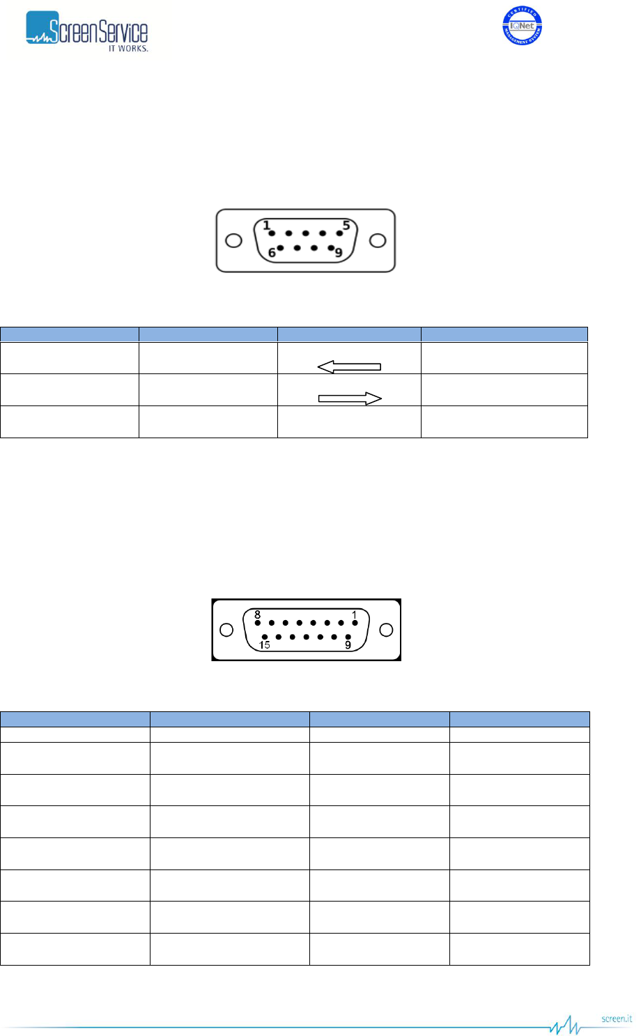
4.3.1 RS232 pinout
Usually personal computers use a standard RS 232 DE-9 connector.
Figure 1. DE-9 Male connector
Table 2. RS232 DE-9 pinout
DE-9 Pin
Name
Direction
Description
2
RXD
Receive Data
3
TXD
Transmit Data
5
GND
-
System Ground
4.3.2 TLC pinout
ARK6 has a SUB-D 15p Female connector for OPTOs with customized pin assignments.
Figure 2. TLC connector
Table 3. TLC pinout
Pin
Signal
Pin
Signal
1
IN_OPTO_0
9
O_GND_0
2
IN_OPTO_1
10
O_GND_1
3
IN_OPTO_2
11
O_GND_2
4
IN_OPTO_3
12
O_GND_3
5
OPTO_GND
13
OPTO_GND
6
VCC_P
14
VCC_P
7
GND
15
GND
8
NC
-
-

ISO 9001:2000 Cert. N°4500/1
Version 1.1 SDT_ARK6_User_Manual_ENG_vATSC Page 24 of 206
4.3.3 TLS pinout
ARK6 has a SUB-D 25p Female connector for Relays with customized pin assignments.
Figure 3. TLS connector
Table 4. TLS pinout
Pin
Signal
Pin
Signal
1
RL_NC0
14
RL0_NC0
2
RL_COM0
15
RL0_COM0
3
RL_NO0
16
RL0_NO0
4
RL_NC1
17
RL1_NC1
5
RL_COM1
18
RL1_COM1
6
RL_NO1
19
RL1_NO1
7
RL_NC2
20
RL2_NC2
8
RL_COM2
21
RL2_COM2
9
RL_NO2
22
RL2_NO2
10
RL_NC3
23
RL3_NC3
11
RL_COM3
24
RL3_COM3
12
RL_NO3
25
RL3_NO3
13
NC
-
-

ISO 9001:2000 Cert. N°4500/1
Version 1.1 SDT_ARK6_User_Manual_ENG_vATSC Page 25 of 206
4.4 Power Supply
IEC
1
Voltage
80 – 264 VAC
Frequency
50 – 60 Hz
ARK6 1U Mains Consumption [Test on ch. 21]
MODE
PWR [dBm]
Vac [Volt]
Iac[Amp]
Consumption [W]
ST-BY
-
225
0,35
78,8
Power OFF
-
225
0,40
90,0
Power ON
21
225
0,62
139,5
Power ON
31
225
0,64
144,0
Power ON
37
225
0,71
159,8
Power ON
41
225
0,80
180,0
ARK6 2U Mains Consumption [Test on ch. 21]
MODE
PWR [dBm]
Vac [Volt]
Iac[Amp]
Consumption [W]
ST-BY
-
225
0,35
78,8
Power OFF
-
225
0,40
90,0
Power ON
40
225
1.9
425
Power ON
47
225
2.9
650
Power ON
50
225
3.7
830
Power ON
52
225
4.4
990
Power ON
53 (1)
225
4.9
1100
Note to the table:
(1) If required.

ISO 9001:2000 Cert. N°4500/1
Version 1.1 SDT_ARK6_User_Manual_ENG_vATSC Page 26 of 206
ARK6 3U Mains Consumption [Test on ch. 45]
MODE
PWR [dBm]
Vac [Volt]
Iac[Amp]
Consumption [W]
ST-BY
-
225
0,35
78,8
Power OFF
-
225
0,40
90,0
Power ON
43
225
2.8
630
Power ON
50
225
4.5
1010
Power ON
53
225
5.7
1280
Power ON
55
225
6.8
1530
Power ON
56 (1)
225
7.4
1660
Note to the table:
(1) If required.

ISO 9001:2000 Cert. N°4500/1
Version 1.1 SDT_ARK6_User_Manual_ENG_vATSC Page 27 of 206
4.5 Environmental Specification
Climatic Temperature range operating
0 °C to +40 °C (+32 °F to +104 °F)
Temperature range within specs
+5 °C to +45 °C (41 °F to +113 °F)
Temperature range storage
-30 °C to +70 °C (-22 °F to +158 °F)
Humidity operating
max 90% RH
EMC
Compliant to EN50022 (emission)
and EN55024 (immunity)
Safety
Compliant to EN60950-1
RoHs
Compliant with directive 2002/95/EC
4.6 Mechanical Specification
Cabinet
19” wide, 1RU high
Width
19” (483 mm)
Height
1U: 44 mm (1.75”)
2U: 88 mm (3.5”)
3U: 132mm (5.25”)
Cooling
Long life fans to assist natural
convection
Transport and storage
Vibration acc. to IEC Publ.68
ISO 9001:2000 Cert. N°4500/1
Version 1.1 SDT_ARK6_User_Manual_ENG_vATSC Page 28 of 206
5 Java Graphic User Interface
The Java Graphic User Interface, stored in the board File System, is downloaded to the local PC every
time the user connects to the board with a Web Browser. A proper Java Virtual Machine is needed; refer
to the Appendix B for a description of supported Java and Internet Browsers.
5.1 Authentication Option
In order to prevent unauthorized users from accessing ARK6 devices via Java Graphic User Interface, an
authentication mechanism can be enabled by means of a factory setting. The name/password
credentials provide control only over who can open the GUI, and requires that all users know a single
name/password to access it.
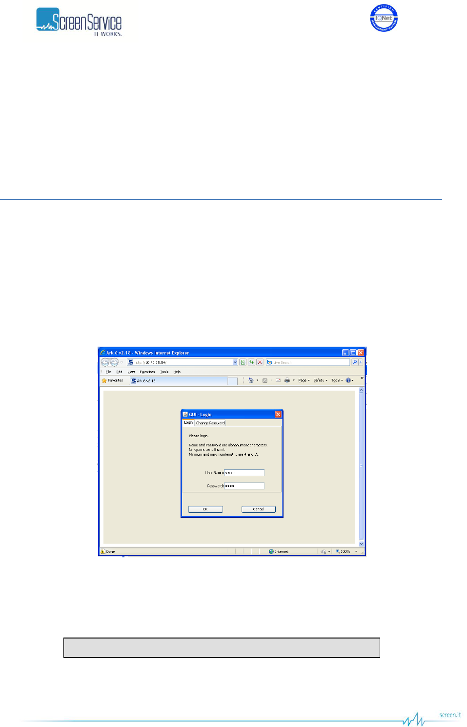
If the authentication mechanism is set for the GUI access, operators will be prompted to enter User
Name and Password before they can have read/write access. The following figure shows the window
that appears as soon as an operator tries to access the Java GUI.
Figure 4. GUI - Login
Enter your User Name and Password and then click “OK” in order to log in.
The default factory login credentials are:
Use the Change Password tab to change your credentials.
User name: “screen” Password: “0000”
ISO 9001:2000 Cert. N°4500/1
Version 1.1 SDT_ARK6_User_Manual_ENG_vATSC Page 29 of 206
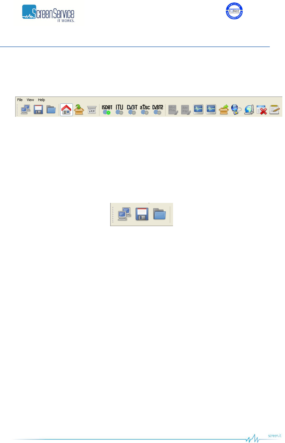
5.2 Java Menu Bar
The following figure shows the menu bar of the Java Graphic User Interface. It allows the switching
between control pages that will be described in detail in next chapters.
Figure 5. Java menu bar
The following controls are provided:
System commands bar allows to enable of the following commands:
Connect: releases/acquires the connection to the device.
Save: saves the device configuration.
Load: loads the last saved configuration.
Figure 6. System commands bar
Operation pages bar allows to switch between the following windows:
Home Page: shows the firmware updating status, allows to reset the device, to locally
download the *.jar file, to enable the Stand-by mode and to switch between operative modes.
Input: shows ASI, GbE and Tuner input statistics.
Tuner: allows to monitor input channel, frequency offset, signal level and quality and to
monitor the Front-End demodulation parameters.
ITU: allows to monitor and to set the ITU specific parameters.
ISDB-T: allows to monitor and to set the ISDB-T specific parameters.
DVB-T: allows to monitor and to set the DVB-T specific parameters.
ATSC: allows to monitor and to set the ATSC specific parameters.
DVB-T2: allows to monitor and to set the DVB-T2 specific parameters.
Mod. Pha.: allows to manage the linear compensation curves.
AM PM: allows to manage the non-linear compensation curves.
Adaptive Linear Precorrection: allows to manage the adaptive linear compensation.
Adaptive Non Linear Precorrection: allows to manage the adaptive non linear compensation.
Outputs: allows to set clock and output parameters and to monitor the hardware status.

ISO 9001:2000 Cert. N°4500/1
Version 1.1 SDT_ARK6_User_Manual_ENG_vATSC Page 30 of 206
Network: allows to monitor the Network settings of both GbE port 1 and GbE port 2 and to set
in/out Ethernet channels parameters.
GPS: shows received GPS statistics and provides commands to manage the Holdover
functionality.
Alarms: provides a grid where to set LCD, Graphic User Interface, Events, Relays, Traps, Input
Switch and RF Off alarm masks.
Events: shows the board events log and allows the manual setting of date and time.
Figure 7. Operation pages bar
System menu allows to access the same commands and windows as System commands and Operation
pages bars do, plus management options, help and version information (refer to System menu
paragraph).
Figure 8. System menu
A brief description of all the provided information and controls follows in the next paragraphs.
ISO 9001:2000 Cert. N°4500/1
Version 1.1 SDT_ARK6_User_Manual_ENG_vATSC Page 31 of 206
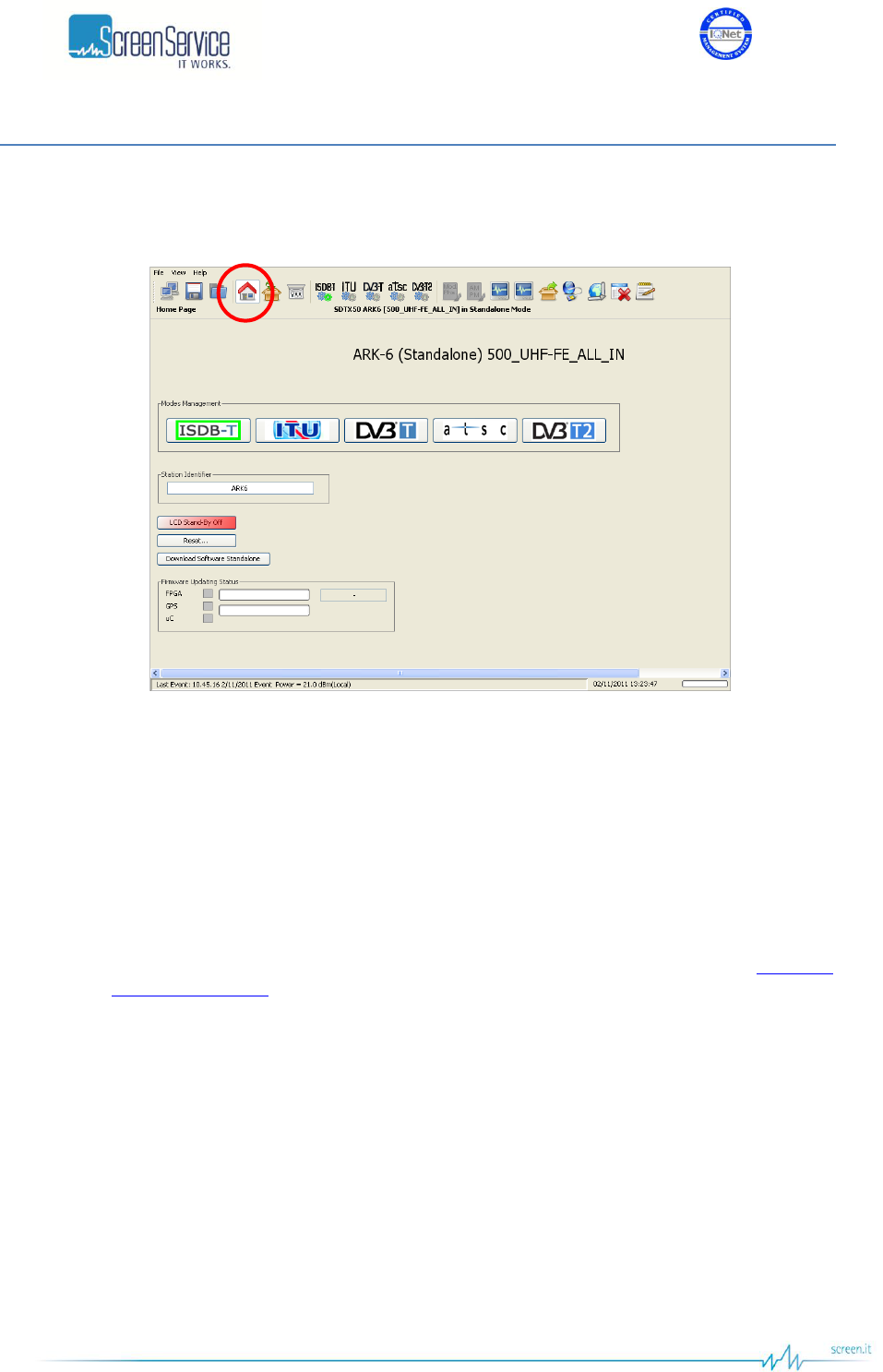
5.3 Home Page
Click on Home Page button, highlighted in the next figure, to access the Home Page.
Figure 9. Home Page window
The Home Page provides a general description of the equipment, the firmware updating status and a
subset of commands here below described:
Modes Management: shows the list of all the available modes, identified by their transmission
standard, and allows to switch between them.
Station Identifier: shows and sets the station name.
LCD Standby: enables the LCD Stand-by button.
Reset: resets the equipment.
Download Software Standalone: performs a local download of the *.jar file (refer to Download
Software Standaloneparagraph).
Firmware Updating Status: the three indicators turn into:
o Yellow during FPGA, uC and GPS updating;
o Green when the updating process is finished (FPGA and uC);
o Grey when new code has been loaded (after next system reset).
The progress bars, at the right side of the FPGA and GPS indicators, show the status of firmware
loading process into FLASH. The FPGA and GPS indicators remain yellow until the new firmware
is loaded. When either FPGA or uC indicators turn into green, the transmitter shall be reset in
order to load the new software.
In the Home Page is also specified the installer version the device has been loaded with.
ISO 9001:2000 Cert. N°4500/1
Version 1.1 SDT_ARK6_User_Manual_ENG_vATSC Page 32 of 206
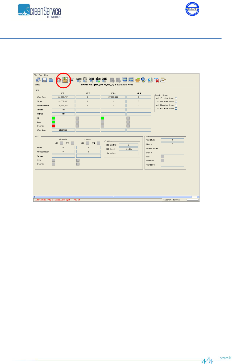
5.4 Input
Click on Input button, highlighted in the next figure, to monitor the input statistics window.
Figure 10. ATSC / DVB-T/T2 Input window
The Input window allows to monitor Transport Stream and SDI input statistics and to enable the cable
equalizer bypass of each one of them.

ISO 9001:2000 Cert. N°4500/1
Version 1.1 SDT_ARK6_User_Manual_ENG_vATSC Page 33 of 206
Table 5. Input window
Box
Parameter / Control
Description
Admitted Ranges / Values
ASI
Word rate
Input word rate.
Approximately 27 Mword/s
Tuner
Word rate
Input byte rate.
ASI - Tuner
Bitrate
Input bitrate.
ASI - Tuner
Filtered bitrate
Bitrate actually used by the modulator.
Zero when the input has not been
selected
Equal to the total bitrate, when
Delete Null Packets disabled
Less than total bitrate, when Delete
Null Packets enabled
ASI - Tuner
Format
Format of received TS Packets.
188 Bytes
204 Bytes
ASI
CD
ASI Carrier detect.
Green: Detected
Grey: Not detected
ASI - Tuner
Lock
The actual synchronization of the Transport Stream. It depends on
the number of correct sync bytes necessary for the device to
synchronize and on the number of destroyed sync bytes witch the
device cannot cope with.
Five consecutive correct sync bytes are sufficient for sync
acquisition, and two or more consecutive corrupted sync bytes
indicate sync loss (Ref. to ETSI TR 101 290)
Green: Locked
Grey: Not locked

ISO 9001:2000 Cert. N°4500/1
Version 1.1 SDT_ARK6_User_Manual_ENG_vATSC Page 34 of 206
Box
Parameter / Control
Description
Admitted Ranges / Values
ASI - Tuner
Overflow
TS input overflow indicator. This alarm condition occurs when the
input bit-rate exceeds the capability of the modulation (Ref. to ETSI
EN 302 755).
Red: Alarm On
Grey: Alarm Off
ASI
Word Errors
Input error rate: word errors per second.
Tuner
Word Errors
Input error rate: Byte errors per second.
Equalizer Bypass
ASI 1/2/3/4 Equalizer
Bypass
Equalizer Bypass
1/2/3/4
Enables/disables the bypassing of cable equalizers at ASI/SDI
inputs.
Checked: Cable equalizer is
bypassed
Not checked: Cable equalizer is
used
GbE 2–
Channel 1/2
Protocol
Ethernet input packets protocol.
UDP
RTP
GbE 2–
Channel 1/2
Bitrate
Bitrate of TS from Ethernet input.
GbE 2–
Channel 1/2
Filtered bitrate
Bitrate actually used by the modulator.
Zero when the input is not selected
Equal to the total bit-rate, when
Delete Null Packets disabled
Less than total bit-rate, when Delete
Null Packets enabled
GbE 2–
Channel 1/2
Format
Format of received TS Packets.
188 Bytes
204 Bytes
GbE 2–
Channel 1/2
Lock
TS lock status. The input Transport Stream is unlocked when more
than two consecutive Sync Byte are missed then five consecutive
Sync Bytes must occur to regain the lock (Ref. to ETSI TR 101 290)
Green: Locked
Grey: Not locked

ISO 9001:2000 Cert. N°4500/1
Version 1.1 SDT_ARK6_User_Manual_ENG_vATSC Page 35 of 206
Box
Parameter / Control
Description
Admitted Ranges / Values
GbE 2–
Channel1/2
Overflow
Input GbE overflow alarm status. This alarm condition occurs when
the input bit-rate exceeds the capability of the modulation (Ref. to
ETSI EN 302 755).
Red: Alarm on
Grey: Alarm off
GbE 2– Statistics
GBE Good Pck
Total amount of frames delivered to the higher-level protocol.
GbE 2– Statistics
GbE Speed
Ethernet connection speed. No duplex information is provided.
10 Mbit//s
100 Mbit//s
1 Gbit//s
GbE 2– Statistics
GBE Bad Pck
The number of inbound packets that contained errors.
SDI 1/2/3/4
Lock
Shows the presence of a valid SDI input stream.
Green: Locked
Grey: Not locked
SDI 1/2/3/4
CD
Shows that the SDI input signal carrier has been correctly locked.
Green: Locked
Grey: Not locked
SDI 1/2/3/4
Ch1-2
Shows that the SDI input audio data have been correctly locked.
Green: Locked
Grey: Not locked
SDI 1/2/3/4
Ch3-4
Shows that the SDI input audio data have been correctly locked.
Green: Locked
Grey: Not locked
SDI 1/2/3/4
Ch 1/2/3/4 Level
[dBFS]
Shows the embedded digital audio level. Measured in dB difference
from the max digital level.
0 down to -114dB

ISO 9001:2000 Cert. N°4500/1
Version 1.1 SDT_ARK6_User_Manual_ENG_vATSC Page 36 of 206
Box
Parameter / Control
Description
Admitted Ranges / Values
SDI 1/2/3/4
Standard
Shows the video standard detected for the SDI input.
NTSC 4:2:2 component video;
NTSC 4:2:2 16x9 component video;
NTSC 4:4:4 13,5 MHz component
video;
PAL 4:2:2 component video;
PAL 4:2:2 16x9 component video;
PAL 4:4:4 13,5 MHz component
video"
Layers Rates
Layer A/B/C
Rate [bit/s]
Bitrate actually used by the modulator.
Used in remux mode only
Layers Rates
Layer A/B/C
Overflow
Layer input overflow alarm status. This alarm condition occurs when
the input bit-rate exceeds the capability of the modulation
Used in remux mode only.
Red: Alarm on
Grey: Alarm off
Layers Rates
Layer A/B/C
Underflow
Layer input underflow alarm status.
Used in remux mode only.
Red: Alarm on
Grey: Alarm off
ISO 9001:2000 Cert. N°4500/1
Version 1.1 SDT_ARK6_User_Manual_ENG_vATSC Page 37 of 206
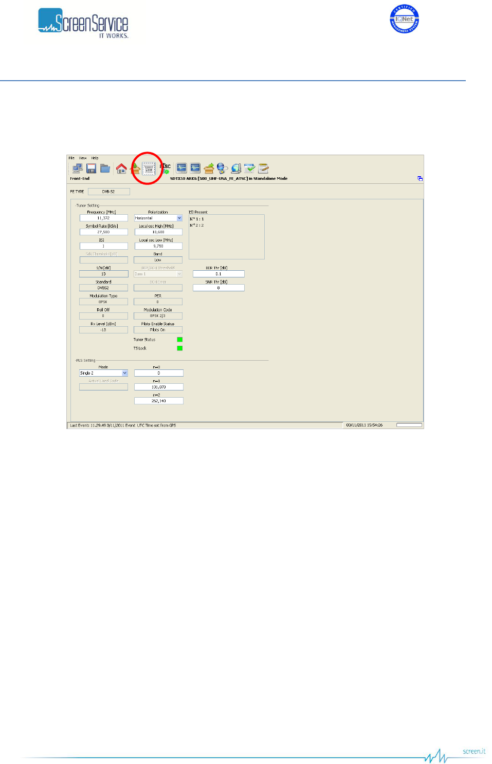
5.5 Front-End
Click on Front-End button, highlighted in the next figure, to access the tuner window.
Figure 11. Front-End window
Use the Tuner window to monitor input channel, frequency offset, signal level and quality, and to
monitor the RF input demodulation parameters.
The Tuner window is composed by the following sections:
RF power level monitor;
Demodulation parameters;
Constellation (DVB-T/T2).
Tuner window changes on the basis of the Front-End type. The available FE types are:
DVB-T/T2
ISDB-T
Digitizer
ATSC
DVB-S2
DVB-S2 CAM
A brief description of the features of each Tuner panel follows in next paragraphs.
ISO 9001:2000 Cert. N°4500/1
Version 1.1 SDT_ARK6_User_Manual_ENG_vATSC Page 38 of 206
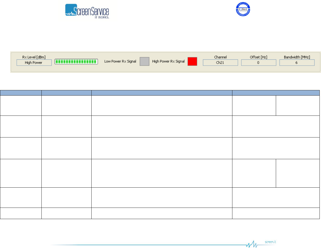
5.5.1 Tuner window: RF power level monitor
Figure 12. Tuner window: RF power level monitor
Table 6. Tuner window: RF power level monitor
Box
Parameter / Control
Description
Admitted Ranges / Values
General
Rx Level [dBm] /
Progress Bar
Input RF power level monitor expressed in dBm.
Min: -84
Max: -21
Low Power
High Power
General
Low Power Rx Signal
This alarm is raised when Max ADC Value is beneath the Low AGC
Threshold and, consequently, both DAT 1 and DAT 2 are at their
minimum values.
Red: Alarm On
Grey: Alarm Off
General
High Power Rx Signal
This alarm is raised when Max ADC Value is beyond the High AGC
Threshold and, consequently, both DAT 1 and DAT 2 are at their
maximum values.
Red: Alarm On
Grey: Alarm Off
General
Channel
This indicator shows the input RF channel.
VHF:
Min: E2
Max: E12
UHF:
Min: 21
Max: 69
General
Offset [Hz]
This indicator shows the input frequency offset.
Min: - 200 kHz
Max: + 200 kHz
General
Bandwidth [MHz]
Input channel bandwidth.
It depends on the FE Type.
ISO 9001:2000 Cert. N°4500/1
Version 1.1 SDT_ARK6_User_Manual_ENG_vATSC Page 39 of 206
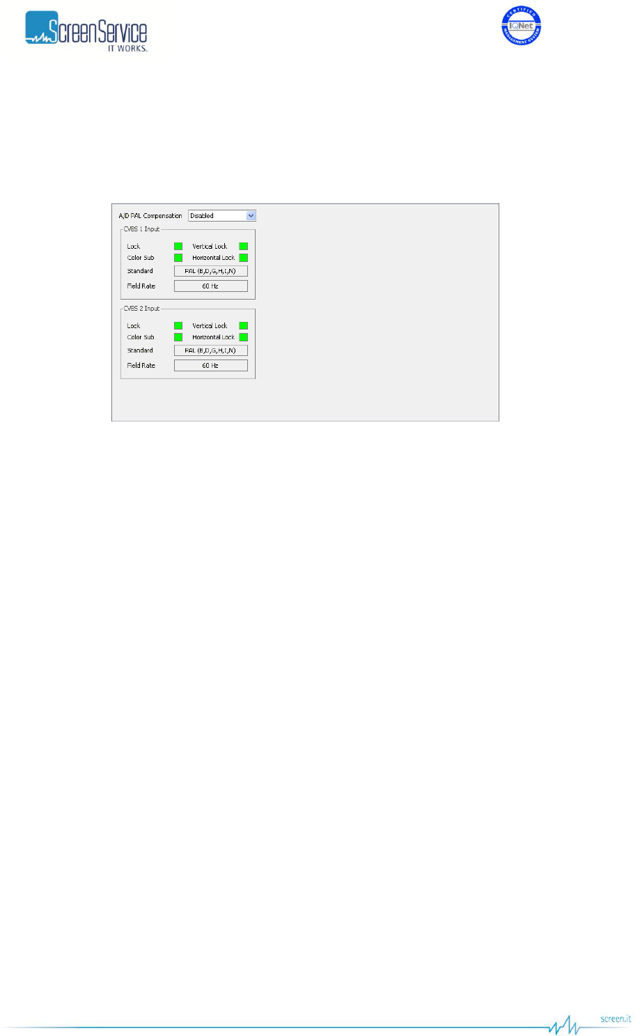
5.5.2 DIGITIZER FE Type
This page shows the available statistics for the analog input video.
Figure 13. CVBS Inputs: Statistics

ISO 9001:2000 Cert. N°4500/1
Version 1.1 SDT_ARK6_User_Manual_ENG_vATSC Page 40 of 206
Table 7. CVBS Inputs: Statistics
Box
Parameter / Control
Description
Admitted Ranges / Values
General
A/D PAL
Compensation
Enable the PAL compensation on digitized video. This features
should be enabled only for particular application e.g. the external
ITS insertion in a PAL-M system.
Enabled
Disabled
CVBS 1/2 input
Lock
General input video signal lock, this is on when the following three
signals are locked.
Green: Locked
Grey: Not locked
CVBS 1/2 input
Vertical lock
Shows the locking of the vertical synchronization signal.
Green: Locked
Grey: Not locked
CVBS 1/2 input
Color sub
Show the locking of the color subcarrier signal.
Green: Locked
Grey: Not locked
CVBS 1/2 input
Horizontal lock
Show the locking of the horizontal synchronization signal.
Green: Locked
Grey: Not locked
CVBS 1/2 input
Standard
Shows the detected input video standard. The video standard
detected must be compatible with the modulation defined for the
device, otherwise a “wrong input standard” alarm is raised.
NTSC (M, J),
PAL (B, D, G, H, I, N),
PAL (M),
PAL (Combination-N),
NTSC,
SECAM,
PAL (60)
CVBS 1/2 input
Field rate
Show the rate of video field refresh
50Hz
60Hz
ISO 9001:2000 Cert. N°4500/1
Version 1.1 SDT_ARK6_User_Manual_ENG_vATSC Page 41 of 206
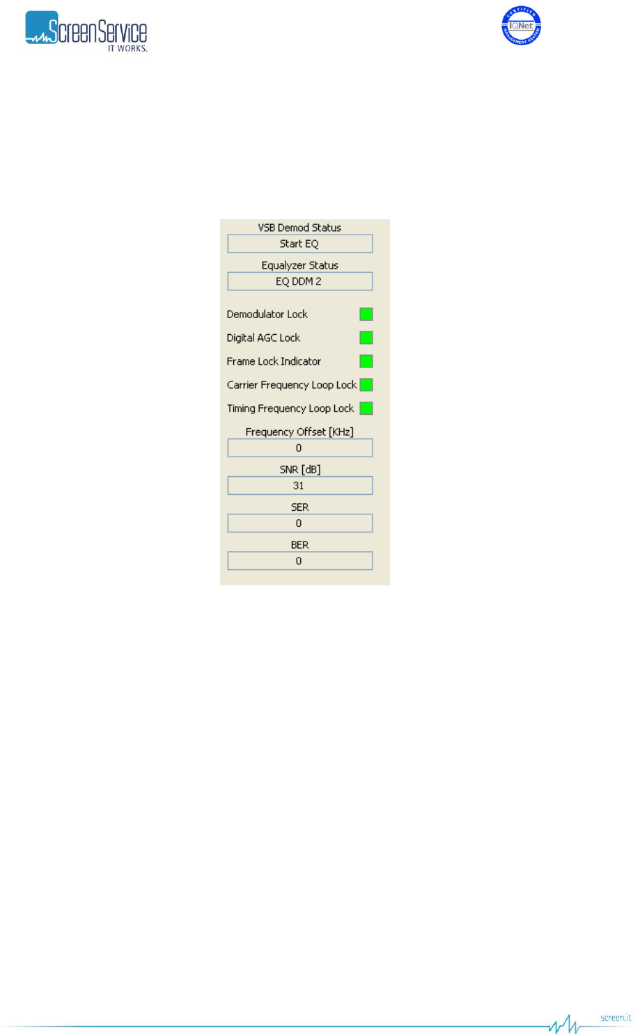
5.5.3 ATSC FE Type
The Tuner panel for the ATSC Front-End shows the status of the demodulator, the input modulation
parameters and the received signal quality.
Figure 14. ATSC RF Input: Status and demodulation parameters

ISO 9001:2000 Cert. N°4500/1
Version 1.1 SDT_ARK6_User_Manual_ENG_vATSC Page 42 of 206
Table 8. ATSC RF Input: Status and demodulation parameters
Box
Parameter / Control
Description
Admitted Ranges / Values
General
VSB Demod Status
VSB demodulation status.
Reset
Reset Wait
AGC Wait 1
AGC Wait 2
Carrier Synchro
NCO Loop
VCXO Wait
Segment Synchro
Tap Computation
Eq Training Mode
Start Eq
Error
General
Equalyzer Status
Equalizer status.
EQ Reset
EQ FFE Train
EQ Blind 1
EQ Blind 2
EQ DDM 1
EQ DDM 2
Error
ISO 9001:2000 Cert. N°4500/1
Version 1.1 SDT_ARK6_User_Manual_ENG_vATSC Page 43 of 206
Box
Parameter / Control
Description
Admitted Ranges / Values
General
Demodulator Lock
Demodulator lock status
Green: Locked
Grey: Unlocked
General
Digital AGC Lock
Digital AGC lock status.
Green: Locked
Grey: Unlocked
General
Frame Lock Indicator
Frame lock status.
Green: Locked
Grey: Unlocked
General
Carrier Frequency
Loop Lock
Carrier frequency loop lock status.
Green: Locked
Grey: Unlocked
General
Timing Frequency
Loop Lock
Timing frequency loop lock status.
Green: Locked
Grey: Unlocked
General
Frequency Offset
[kHz]
Output carrier offset.
General
SNR [dB]
Signal to Noise Ratio [dB]
General
SER
Segment Error Rate.
General
BER
Bit Error Rate.
ISO 9001:2000 Cert. N°4500/1
Version 1.1 SDT_ARK6_User_Manual_ENG_vATSC Page 44 of 206
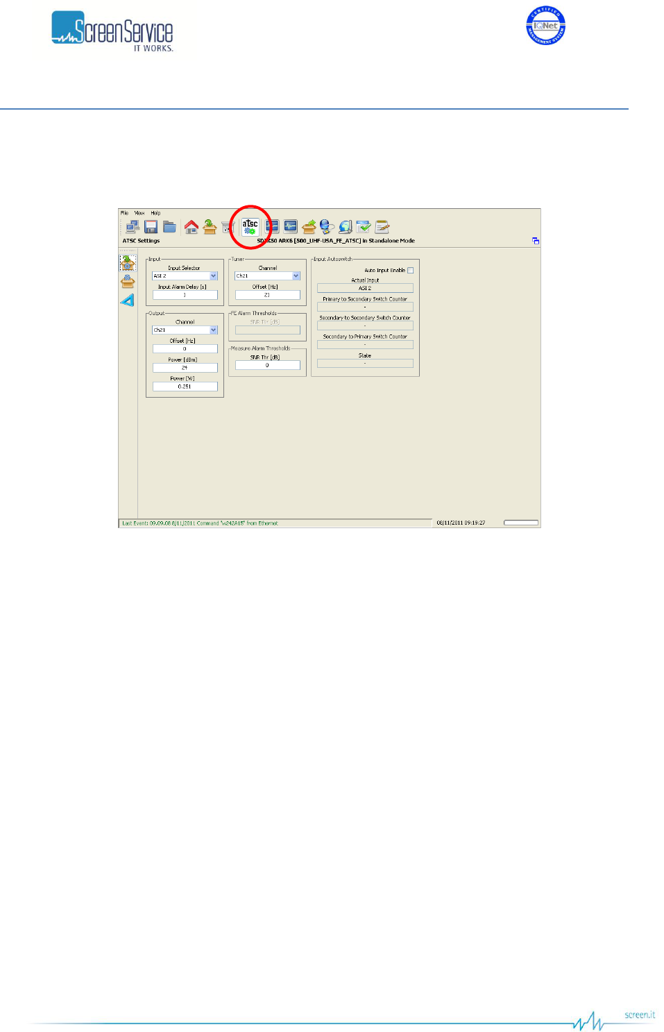
5.6 ATSC
Click on ATSC button, highlighted in the next figure, to access the ATSC window.
Figure 15. ATSC window
Use the ATSC Processing page to manage ATSC specific configuration parameters and to monitor output
signal level and quality.
ISO 9001:2000 Cert. N°4500/1
Version 1.1 SDT_ARK6_User_Manual_ENG_vATSC Page 45 of 206
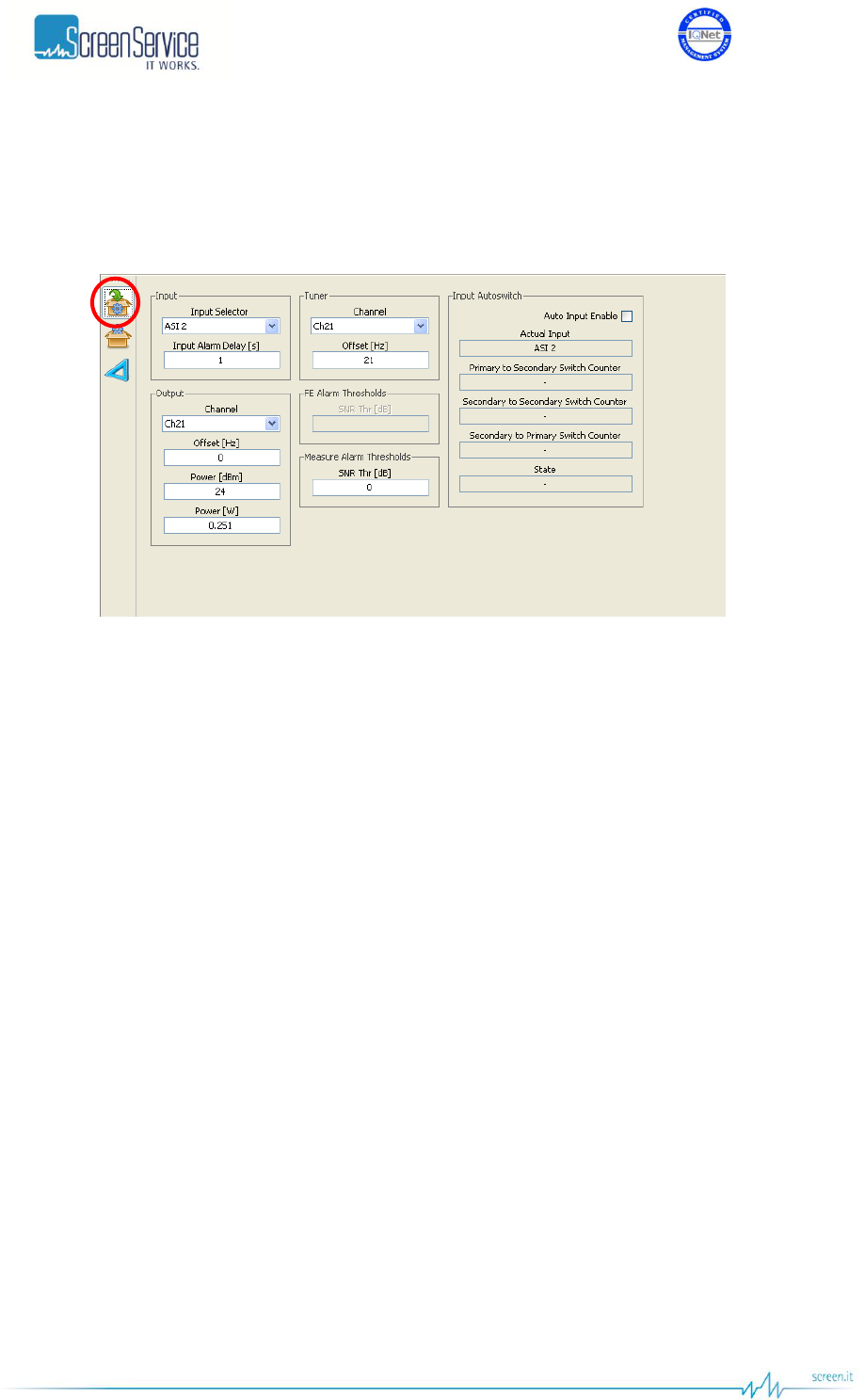
5.6.1 ATSC Settings
Click on the ATSC Settings button, highlighted in the next figure, to access the ATSC general settings.
Figure 16. ATSC Processing: ATSC Settings
Use the ATSC Settings page to select inputs, to set input/output RF channels, offset frequencies,
Frontend and Measure alarm thresholds and to manage Input Autoswitch functionality (refer to
Appendix A for further information).
Settings within this page will be used only in ATSC mode but will be saved and stored as mode specific
controls.

ISO 9001:2000 Cert. N°4500/1
Version 1.1 SDT_ARK6_User_Manual_ENG_vATSC Page 46 of 206
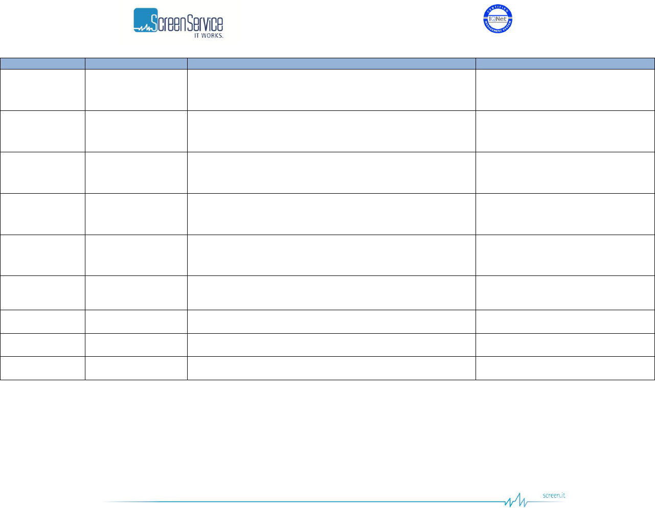
Table 9. ATSC Processing: ATSC Settings
Box
Parameter / Control
Description
Admitted Ranges / Values
Input
Input Selector
Input selector.
It is not allowed to change input until the Input Autoswitch is
enabled. In order to change the primary input, disable the Input
Autoswitch functionality, select a different input through the input
selector and then enable the Input Autoswitch functionality.
ASI 1
ASI 2
ASI 3
ASI 4
Tuner
GbE 2 ch1
GbE 2 ch2
Input
Input Alarm Delay [s]
Time to wait for No Input alarm rising expressed in seconds (refer to
Alarms paragraph).
Note: It is highly recommended to set an Input Alarm Delay value
different from zero so as to allow the input signal locking.
Min: 1 s
Max: 25.5 s
Input Autoswitch
Auto Input Enable
Enables the use of Input Autoswitch finite-state machine.
Refer to Appendix A. for further information.
Enabled
Disabled
Input Autoswitch
Actual Input
Shows the currently used input.
ASI 1
ASI 2
ASI 3
ASI 4
Tuner
GbE 2 ch1
GbE 2 ch2

ISO 9001:2000 Cert. N°4500/1
Version 1.1 SDT_ARK6_User_Manual_ENG_vATSC Page 47 of 206
Box
Parameter / Control
Description
Admitted Ranges / Values
Input Autoswitch
Primary to Secondary
Switch Counter
Primary to secondary input switch countdown expressed in
seconds.
Min: 0 s
Max: *.def file dependant
Default: 25 s
Input Autoswitch
Secondary to
Secondary Switch
Counter
Secondary to secondary input switch countdown expressed in
seconds.
Min: 0 s
Max: *.def file dependant
Default: 25 s
Input Autoswitch
Secondary to Primary
Switch Counter
Secondary to primary input switch countdown expressed in
seconds.
Min: 0 s
Max: *.def file dependant
Default: 300 s
Input Autoswitch
State
Current state of the finite-state machine
Priority Input Locked
Priority Input Not Locked
Searching First Input Locked
Check Priority Input
Tuner
Channel
Input RF channel selector.
Min: 14
Max: 77
Tuner
Offset [Hz]
The receiver frequency will accept offset frequencies in the range
+/- 200 kHz (1 Hz steps).
Min: - 200 kHz
Max: + 200 kHz
FE Alarm
Thresholds
SNR Thr [dB]
FE Signal to Noise alarm threshold.
Min: 10 dB
Max: 50 dB
ISO 9001:2000 Cert. N°4500/1
Version 1.1 SDT_ARK6_User_Manual_ENG_vATSC Page 48 of 206
Box
Parameter / Control
Description
Admitted Ranges / Values
MEAS Alarm
Thresholds
SNR Thr [dB]
Meas Signal to Noise alarm threshold.
Min: 10
Max: 50
Output
Channel
Output channel.
Channel ranges are device’s definition
dependant.
Output
Offset [Hz]
Output frequency offset (expressed in Hz).
Min: -200 kHz
Max: +200 kHz
Output
Power [dBm]
Output power (expressed in dBm).
Output power ranges are device’s
definition dependant.
Output
Power [W]
Output power (expressed in W).
ISO 9001:2000 Cert. N°4500/1
Version 1.1 SDT_ARK6_User_Manual_ENG_vATSC Page 49 of 206
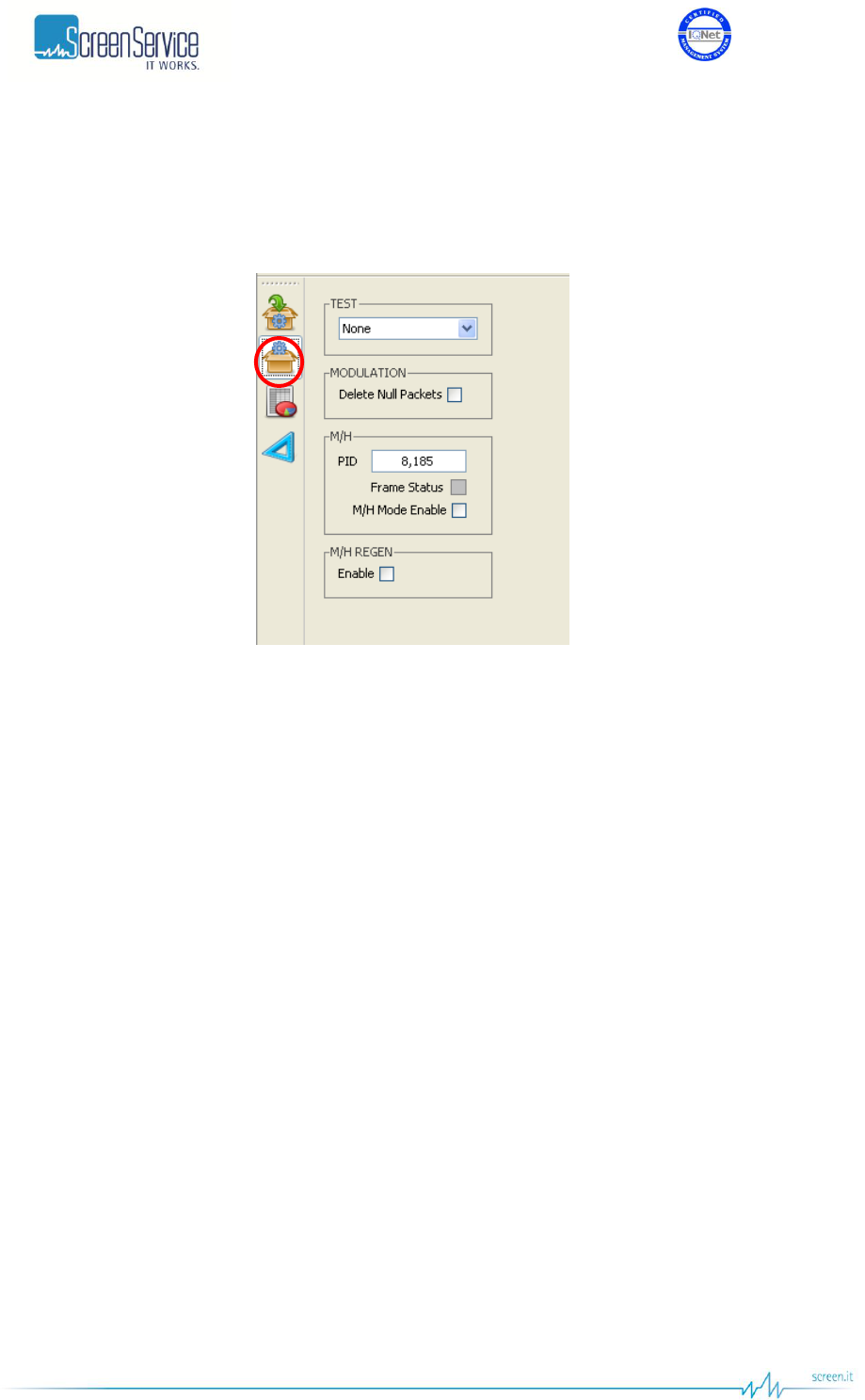
5.6.2 ATSC Modulation
The ATSC Modulation window allows to select test signals and to manage the M/H mode.
Figure 17. ATSC Processing: ATSC Modulation

ISO 9001:2000 Cert. N°4500/1
Version 1.1 SDT_ARK6_User_Manual_ENG_vATSC Page 50 of 206
Table 10. ATSC Processing: ATSC Modulation
Box
Parameter / Control
Description
Admitted Ranges / Values
MODULATION
Delete Null Packets
Delete null packets enabling check box.
Checked: Enabled
Not checked: Disabled
TEST
The selector of test signal.
None
CW
Force Null Packets
M/H
PID
Sets the PID of M/H packets.
Min: 0
Max: 8191
M/H
Frame Status
M/H frame alarm.
Grey: M/H mode disabled
Green: Alarm OFF.
Red: Alarm ON
M/H
M/H Mode Enable
Enables/disables the M/H mode.
Checked: Enabled
Not checked: Disabled
M/H REGEN
Enable
Enables/disables the M/H Regeneration mode.
The maximum M/H total number of groups supported by the M/H
Regeneration mode is 8.
Checked: Enabled
Not checked: Disabled
ISO 9001:2000 Cert. N°4500/1
Version 1.1 SDT_ARK6_User_Manual_ENG_vATSC Page 51 of 206
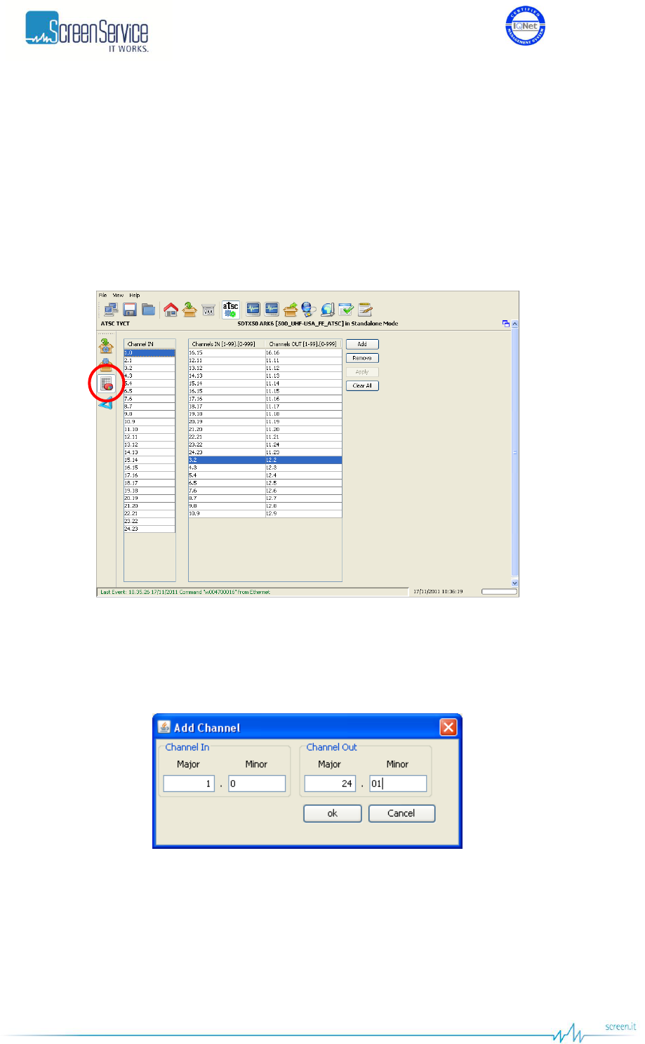
5.6.3 ATSC TVCT
The ATSC TVCT window allows to modify On-The-Fly Major and Minor channel numbers associated with
the virtual channels defined in the incoming TVCT.
If the definition of the current TVCT changes, the version number of the table shall be accordingly
modified otherwise the functioning of the facility is not assured.
Note: On-The-Fly processing of multi-section TVCTs is not supported.
Figure 18. ATSC Processing: ATSC Modulation
Click on Add button to add an entry to the channel numbers table. The insertion of a Channel In being
not defined in the incoming TVCT won’t result in any change in the output TVCT.
Figure 19. ATSC TVCT: Add button
The available controls in the ATSC TVCT windows follow:
Add: Adds an entry to the table.
Remove: Removes an entry from the table.
Apply: Applies the new configuration.
Clear All: Empties the entries of the channel numbers table.
ISO 9001:2000 Cert. N°4500/1
Version 1.1 SDT_ARK6_User_Manual_ENG_vATSC Page 52 of 206
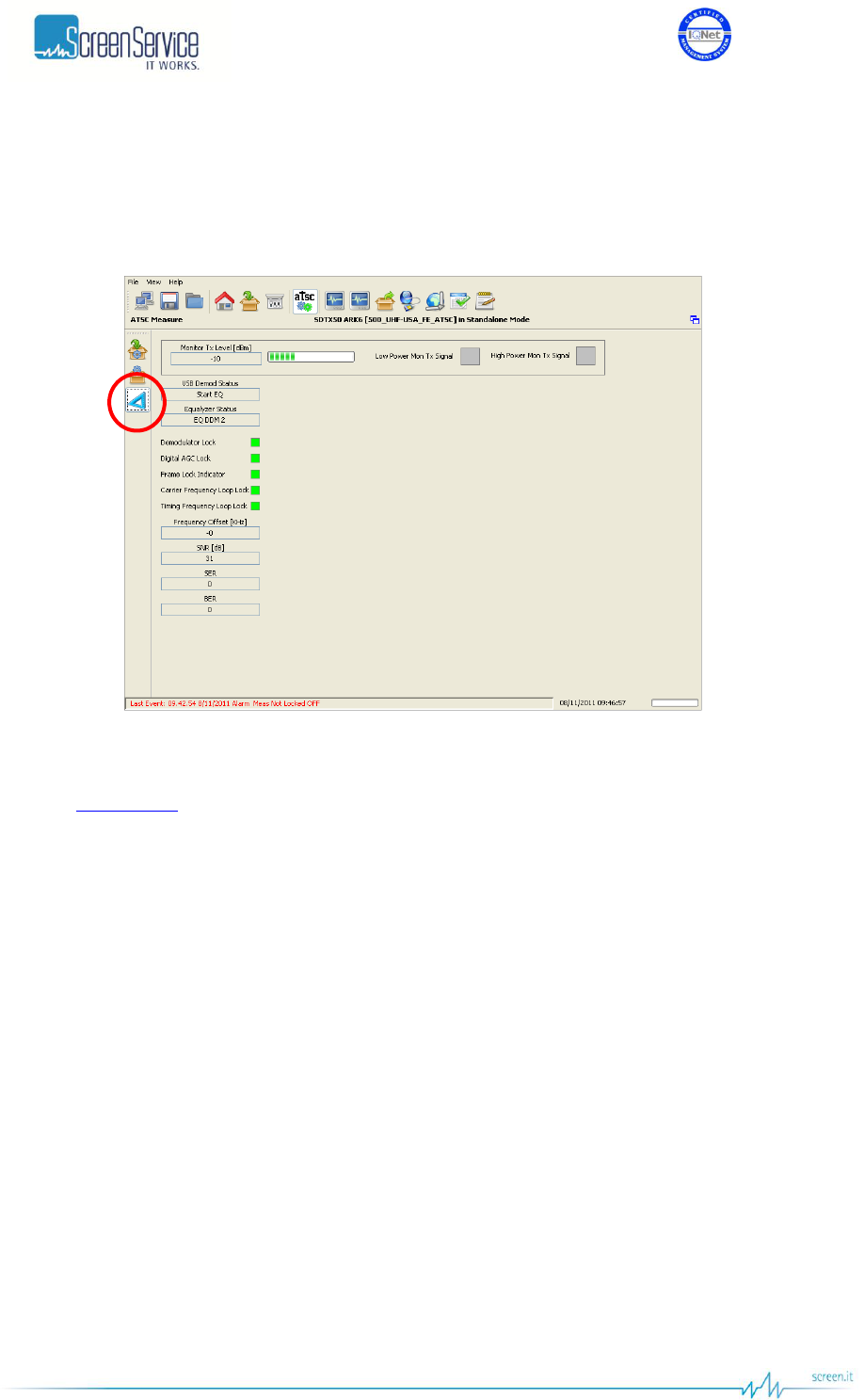
5.6.4 ATSC Measure
Click on Measure button, highlighted in the next figure, to access the measure window.
Figure 20. ATSC Processing: ATSC Measure
Use the Measure window to monitor output signal level and quality.
Refer to ATSC FE Type paragraph for a detailed description of each field within this window.
ISO 9001:2000 Cert. N°4500/1
Version 1.1 SDT_ARK6_User_Manual_ENG_vATSC Page 53 of 206
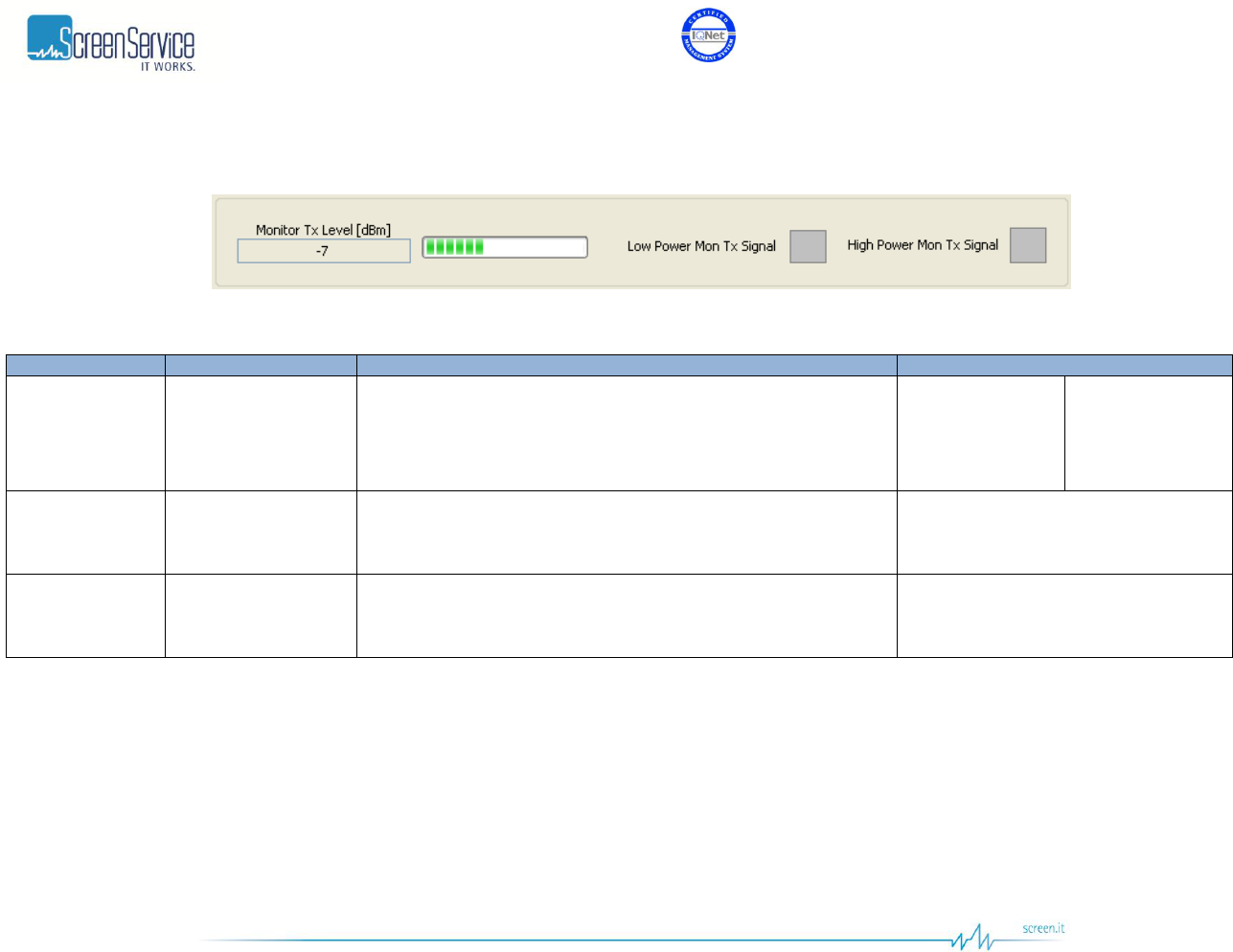
5.6.4.1 ATSC Measure window: RF power level monitor
Figure 21. ATSC Measure: RF power level monitor
Table 11. ATSC Measure: RF power level monitor
Box
Parameter / Control
Description
Admitted Ranges / Values
General
Monitor Tx Level
[dBm] /
Progress Bar
This value is the level of the signal, passing through the
transmission section and re-entering the system after the channel
filter, that will be used for the adaptive compensation.
The tolerance of the read value is ±1 dB.
Min: - 20
Max: 11,5
Low Power
High Power
General
Low Power Tx Signal
This alarm is raised when Max ADC Value is beneath the Low AGC
Threshold and, consequently, input attenuation is at its minimum
level.
Red: Alarm On
Grey: Alarm Off
General
High Power Tx Signal
This alarm is raised when Max ADC Value is beyond the High AGC
Threshold and, consequently, input attenuation is at its maximum
level.
Red: Alarm On
Grey: Alarm Off
ISO 9001:2000 Cert. N°4500/1
Version 1.1 SDT_ARK6_User_Manual_ENG_vATSC Page 54 of 206
5.7 ITU.470
Click on ITU button, highlighted in the next figure, to access the ITU modulator parameters window.
Figure 22. ITU window
Use the ITU Processing page to manage the configuration of the analog modulator.
ISO 9001:2000 Cert. N°4500/1
Version 1.1 SDT_ARK6_User_Manual_ENG_vATSC Page 55 of 206
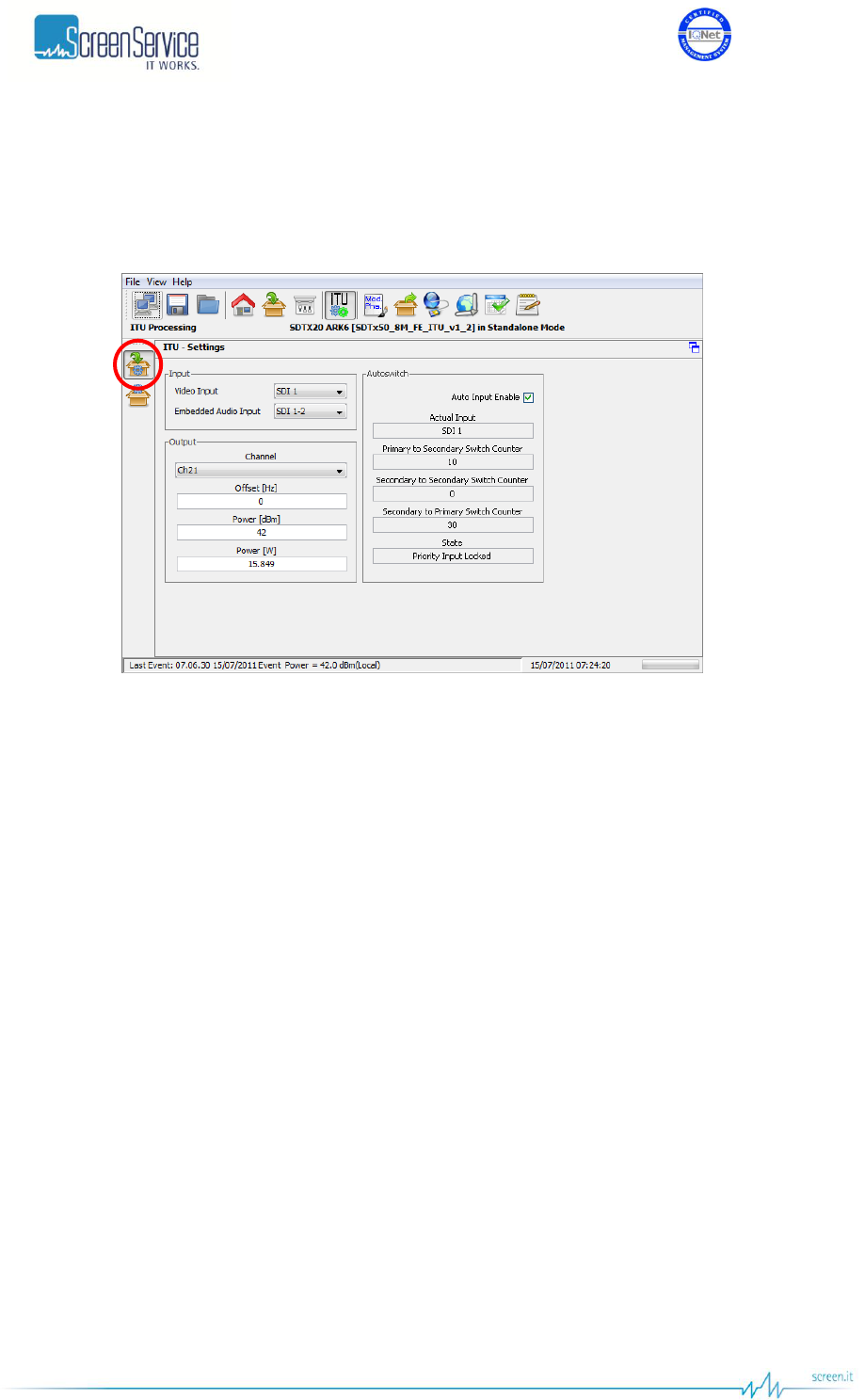
5.7.1 ITU Settings
Click on the ITU Settings button, highlighted in the next figure, to access the ITU general settings.
Figure 23. ITU Processing: ITU Settings
Use the ITU Settings page to select inputs, to set input/output RF channels, offset frequencies, Frontend
and Measure alarm thresholds and to manage Input Autoswitch functionality (refer to Appendix A for
further information).
Settings within this page will be used only in ITU mode but will be saved and stored as mode specific
controls.

ISO 9001:2000 Cert. N°4500/1
Version 1.1 SDT_ARK6_User_Manual_ENG_vATSC Page 56 of 206
Table 12. ITU Processing: ITU Settings
Box
Parameter / Control
Description
Admitted Ranges / Values
Input
Video input
Video input selector.
Use this control to select one of the available video inputs. CVBS
analog inputs are available only when the A/V frontend is available.
When and SDI input is selected, the embedded audio channel for
that input are modulated and the user can select between channel
1-2 and channel 3-4. When CVBS input is selected the relative
analog audio input channels are used.
SDI 1
SDI 2
SDI 3
SDI 4
CVBS 1
CVBS 2
Input
Embedded audio
input
Embedded audio channels selector.
When a SDI input is selected this control can be used to send the
embedded audio channels 1-2 or the embedded audio channels 3-4
to the modulation.
Channel 1-2
Channel 3-4
Output
Channel
Output RF channel selector.
Output channel selection depends on the channel planning
definition loaded on the device. The following ranges and values
are typical for Italian/European TV channels.
VHF (BIII EU
option):
Min: E2
Max: E12
UHF (UHF EU
option):
Min: 21
Max: 69
Output
Offset [Hz]
The receiver frequency will accept offset frequencies in the range
+/- 200 kHz (1 Hz steps).
Min: - 200 kHz
Max: + 200 kHz
Output
Power [dBm]
Output power setting.
This control sets the output power in dBm values. Changing this
control will also change the value of power control expressed in W.
Min and Max values depends on the
power class of the device. e.g. for a
SDTX-500 device:
28 dBm up to 48 dBm

ISO 9001:2000 Cert. N°4500/1
Version 1.1 SDT_ARK6_User_Manual_ENG_vATSC Page 57 of 206
Box
Parameter / Control
Description
Admitted Ranges / Values
Output
Power [w]
Output power setting.
This control sets the output power in W. Changing this control will
also change the value of power control expressed in dBm.
Min and Max values depends on the
power class of the device. e.g. for a
SDTX-500 device:
0.63 W up to 63 W
Input Autoswitch
Auto Input Enable
Enables the use of Input Autoswitch finite-state machine.
Refer to Appendix A. for further information.
Enabled
Disabled
Input Autoswitch
Actual Input
Shows the currently used input.
SDI 1
SDI 2
SDI 3
SDI 4
CVBS 1
CVBS 2
Input Autoswitch
Primary to Secondary
Switch Counter
Primary to secondary input switch countdown expressed in
seconds.
Min: 0 s
Max: *.def file dependant
Default: 25 s
Input Autoswitch
Secondary to
Secondary Switch
Counter
Secondary to secondary input switch countdown expressed in
seconds.
Min: 0 s
Max: *.def file dependant
Default: 25 s
Input Autoswitch
Secondary to Primary
Switch Counter
Secondary to primary input switch countdown expressed in
seconds.
Min: 0 s
Max: *.def file dependant
Default: 300 s
ISO 9001:2000 Cert. N°4500/1
Version 1.1 SDT_ARK6_User_Manual_ENG_vATSC Page 58 of 206
Box
Parameter / Control
Description
Admitted Ranges / Values
Input Autoswitch
State
Current state of the finite-state machine
Priority Input Locked
Priority Input Not Locked
Searching First Input Locked
Check Priority Input
ISO 9001:2000 Cert. N°4500/1
Version 1.1 SDT_ARK6_User_Manual_ENG_vATSC Page 59 of 206
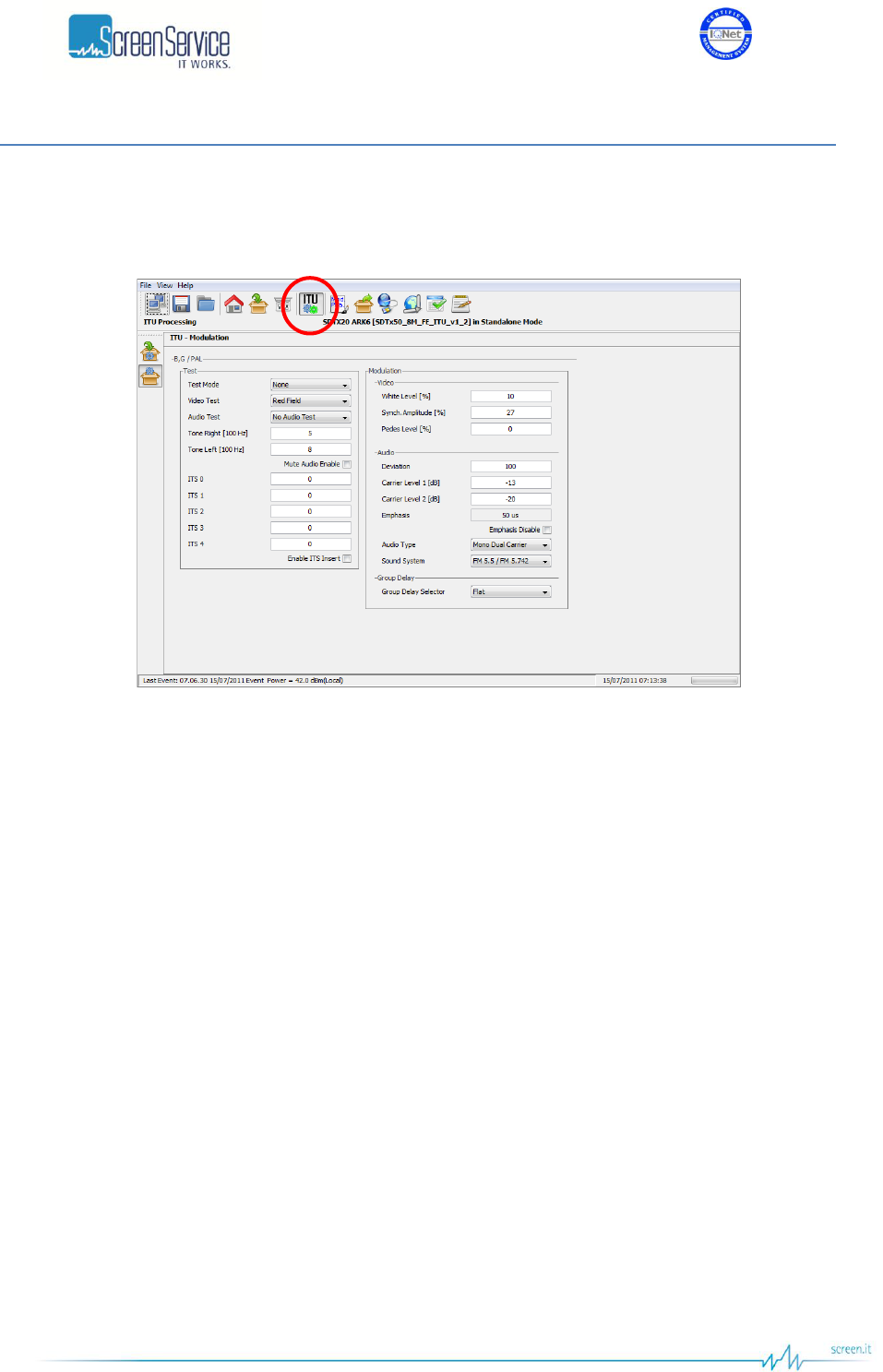
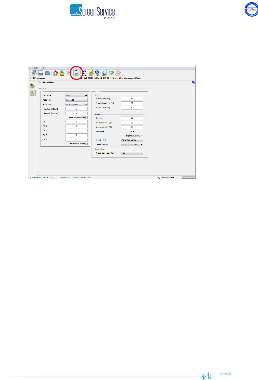
5.7.2 ITU Modulation
The ITU Modulation window allows actual modulation parameters monitoring and setting.
Figure 24. ITU Processing page: ITU Modulation
The ITU Modulation window is composed by the following sections:
Modulator manager;
Test: used to manage RF test modes and Audio-Video test
ISO 9001:2000 Cert. N°4500/1
Version 1.1 SDT_ARK6_User_Manual_ENG_vATSC Page 60 of 206
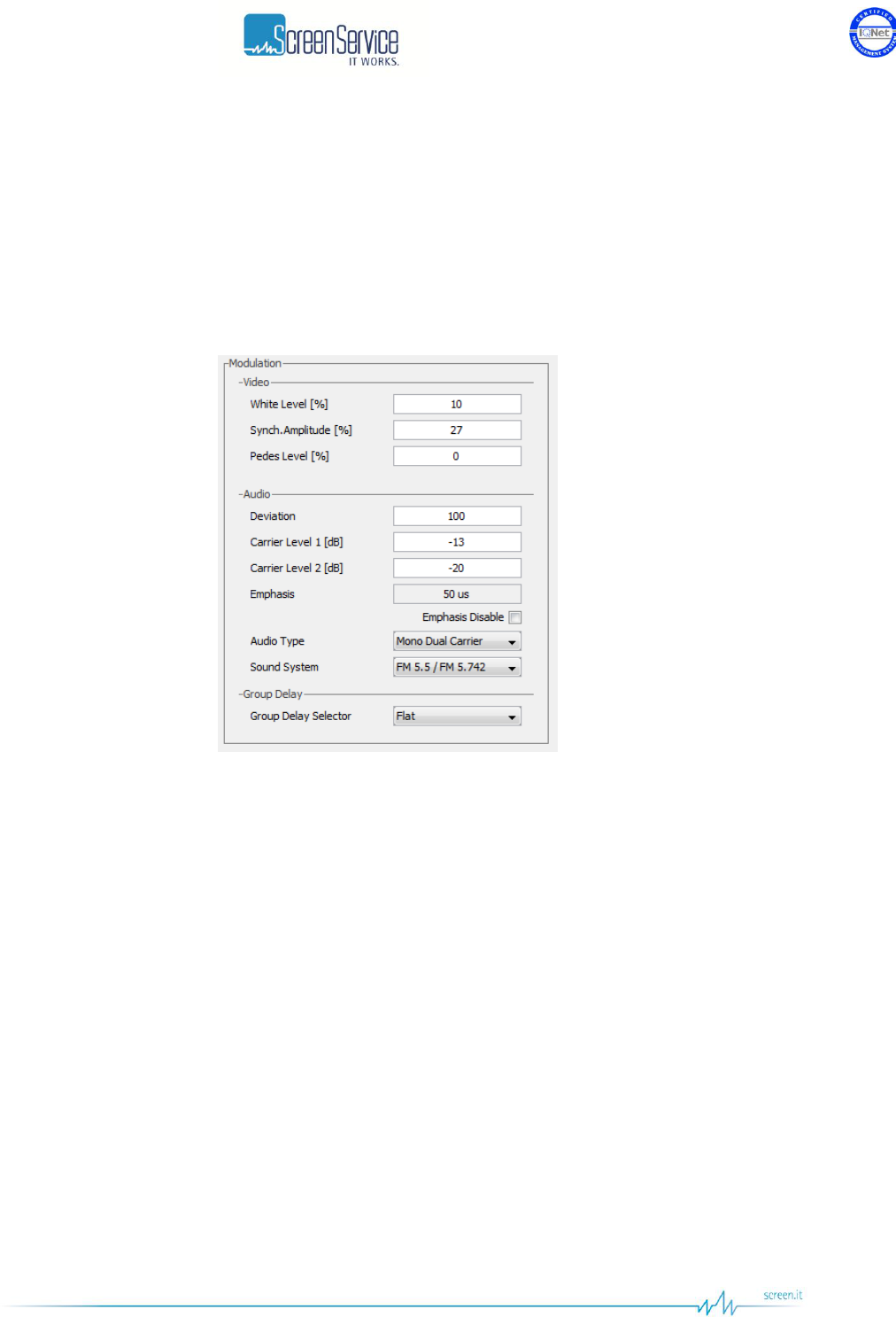
5.7.2.1 ITU Modulation: Modulator manager
Commands and indicators belonging to this section allow to:
Select the video modulation parameters;
Set the audio modulation parameters;
Set the group delay.
Figure 25. ITU Modulation: Modulator manager

ISO 9001:2000 Cert. N°4500/1
Version 1.1 SDT_ARK6_User_Manual_ENG_vATSC Page 61 of 206
Table 13. ITU Modulation: Modulator manager
Box
Parameter / Control
Description
Admitted Ranges / Values
Video
White Level [%]
Video white level setting. The level value is in percentage upon the
synch level. The synch level is taken as 100% reference.
MIN: 10
MAX: 22
Step: 0,05
Video
Synch. Amplitude
[%]
Video synch amplitude setting. The level value is in percentage
upon the synch level. The synch level is taken as 100% reference.
MIN: 22
MAX: 27,5
Step: 0,05
Video
Pedes Level [%]
Video pedes level setting. The level value is in percentage upon the
synch level. The synch level is taken as 100% reference.
MIN: 0
MAX: 7
Step: 0,05
Audio
Deviation
Audio deviation.
This parameter is used to change the frequency deviation of the
audio modulation in order to adjust the audio volume.
Relative values
0 up to 255
Default value 100
Audio
Carrier Level 1 [dB]
Audio 1 carrier level setting.
This parameter is the amplitude difference, expressed in dB values,
between the video carrier and the audio 1 carrier.
MIN: -22
MAX: -7
Step: 1

ISO 9001:2000 Cert. N°4500/1
Version 1.1 SDT_ARK6_User_Manual_ENG_vATSC Page 62 of 206
Box
Parameter / Control
Description
Admitted Ranges / Values
Audio
Carrier Level 2 [dB]
Audio 2 carrier level setting.
This parameter is the amplitude difference, expressed in dB values,
between the video carrier and the audio 1 carrier. Not used for
mono audio carrier configurations such as NTSC or PAL M.
MIN: -22
MAX: -7
Step: 1
Audio
Emphasis
Audio emphasis value monitor.
The audio emphasis used depends on the modulation standard.
50us (used for PAL-BG)
75us
Audio
Emphasis disable
Audio emphasis disable.
This control disables the audio emphasis.
Audio emphasis enabled (not
ticked);
Audio emphasis disabled (ticked).
Audio
Audio type
Audio modulation type selection.
This control selects the audio modulation mode. Stereo and dual
carrier modes are not available for standards that support mono
audio only.
Mono dual carrier;
Dual sound;
Stereo;
Mono single carrier.
Audio
Sound system
Audio carrier spacing selector.
This control shows more options for the standard that supports
more than one audio carrier spacing.
FM 5.5/5.742
Group delay
Group delay selector
Select the group delay to apply.
The available group delay curve depends on the group delay
definition loaded on the device.
e.g. for PAL BG:
Flat (no group delay curve)
Curve A
Curve B
ISO 9001:2000 Cert. N°4500/1
Version 1.1 SDT_ARK6_User_Manual_ENG_vATSC Page 63 of 206
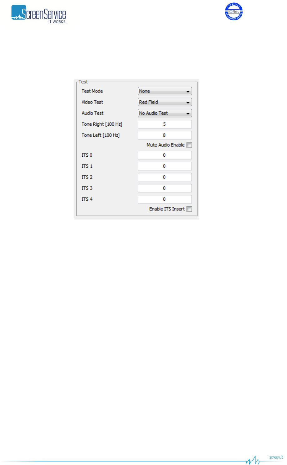
5.7.2.2 ITU Modulation: Modulator test controls
The following controls enable the testing of RF signal, audio and video.
Figure 26. ITU Modulation: Modulator test modes

ISO 9001:2000 Cert. N°4500/1
Version 1.1 SDT_ARK6_User_Manual_ENG_vATSC Page 64 of 206
Table 14. ITU Modulation: Modulator test modes
Box
Parameter / Control
Description
Admitted Ranges / Values
Test
Test mode
Enables one of the available test modes for RF signal.
None;
CW: non modulated carrier at
centre frequency;
CW AV: non modulated video and
audio carriers;
Test
Video test
Enables one of the available video test signals.
Input video. No test signal;
SMPTE bars;
Horizontal bars;
Red field.
Test
Audio test
Enables one of the available audio test signals.
No audio test;
Test tone. Sin waves at the
selected frequency on left and right
channel. (Left only for mono
modulations)
Test
Tone right [100 Hz]
Set the frequency of the right channel test tone. Base unit is
100Hz.
Base unit 100 Hz;
0 up to 127, 0 up to 12.7 kHz.
Test
Tone left [100 Hz]
Set the frequency of the right channel test tone. Base unit is
100Hz.
Base unit 100 Hz;
0 up to 127, 0 up to 12.7 kHz.
Test
Mute audio enable
Enables the audio carriers’ suppression for test purposes.
Mute audio disabled: audio carries
are transmitted;
Mute audio enabled: audio carriers
are suppressed.
ISO 9001:2000 Cert. N°4500/1
Version 1.1 SDT_ARK6_User_Manual_ENG_vATSC Page 65 of 206
Box
Parameter / Control
Description
Admitted Ranges / Values
Test
ITS 0
Select the line where to inject the ITS 0 when the enable ITS insert
option is enabled.
Min: 7
Max: 622
Test
ITS 1
Select the line where to inject the ITS 1 when the enable ITS insert
option is enabled.
Min: 7
Max: 622
Test
ITS 2
Select the line where to inject the ITS 2 when the enable ITS insert
option is enabled.
Min: 7
Max: 622
Test
ITS 3
Select the line where to inject the ITS 3 when the enable ITS insert
option is enabled.
Min: 7
Max: 622
Test
ITS 4
Select the line where to inject the ITS 4 when the enable ITS insert
option is enabled.
Min: 7
Max: 622
Test
Enable ITS insert
Enables the insertion of Injected Test Signals in the selected video
lines.
Min: 7
Max: 622
ISO 9001:2000 Cert. N°4500/1
Version 1.1 SDT_ARK6_User_Manual_ENG_vATSC Page 66 of 206
5.8 Manual compensation
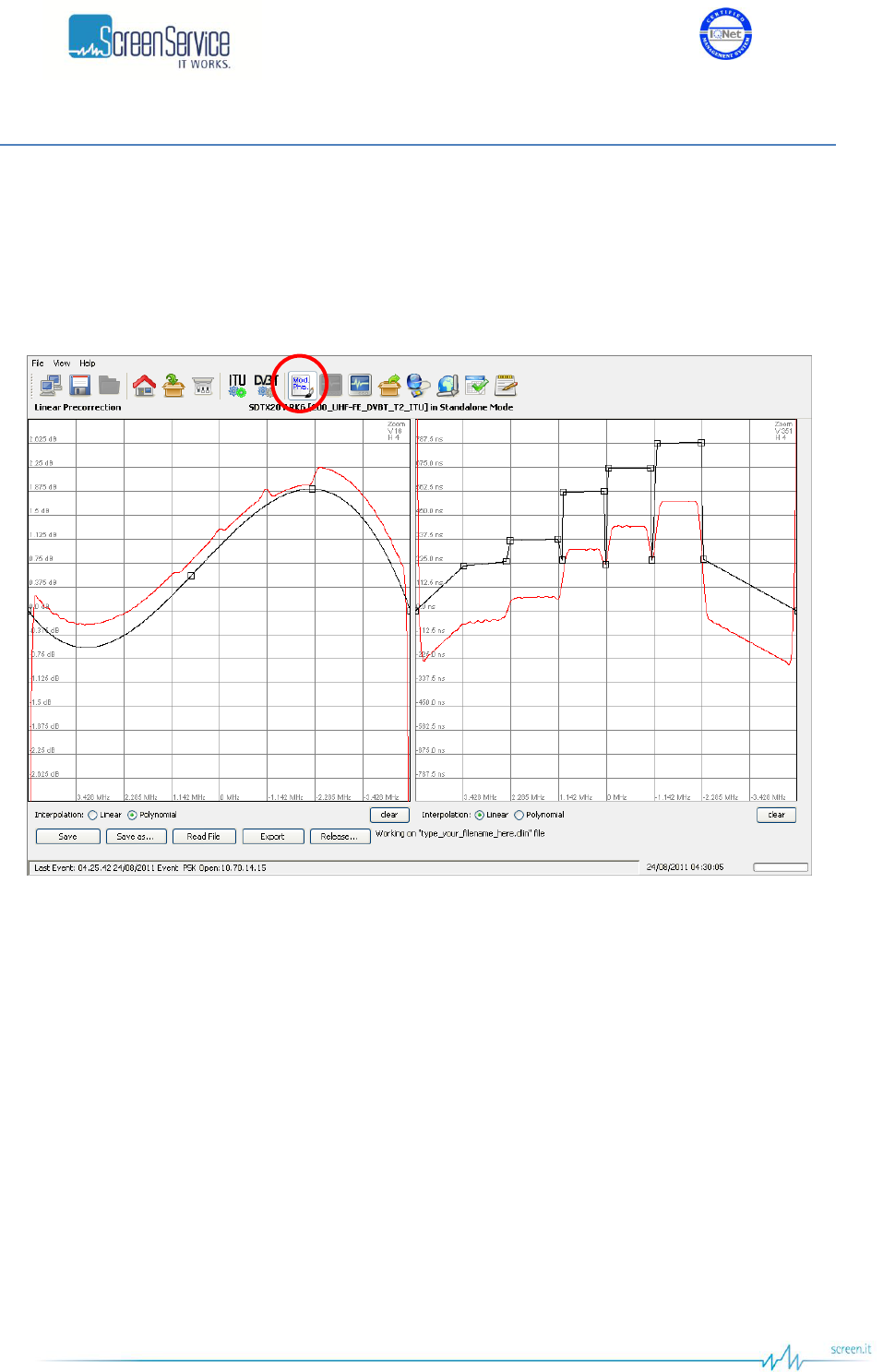
5.8.1 Linear Precorrection
Click on Linear Precorrection button, highlighted in the next figure, to access the filter window.
Figure 27. Adaptive Linear Precorrection
The ARK6 system provides a pre-correction tool for Module&Phase output signal pre-correction.
This tool provides two grids for the drawing of:
Module of the filter’s curve.
Group Delay of the filter’s curve.
The two curves are used to calculate the linear pre-correction coefficients. The curves are drawn by the
interpolation of 1024 points referring to the points inserted and using a linear or polynomial
interpolation algorithm.
Knob points can be added with a left-click of the mouse on the grid and deleted with a right-click, drag
and move a point to change the curve.
Each coefficient variation, due to curves change, is saved in the FPGA “runtime” memory registers and
dynamically changes the device’s output.
The tool is prevented to send an “overflowing” amount of data to the device: curve changes will be
applied only when the mouse button is released.

ISO 9001:2000 Cert. N°4500/1
Version 1.1 SDT_ARK6_User_Manual_ENG_vATSC Page 67 of 206
In the module grid, the red curve is used to monitor the current module curve calculating and saving.
The last saved coefficients are locally downloaded from the FPGA runtime memory registers in order to
redraw the curve.
Remember to click on the Save as button the first time you change the factory default curves in order to
do not overwrite them.
The following buttons allow the management of linear pre-correction files and the management of the
connection to port 5000:
Save: used to save in the device memory the current curves setting. The previously saved file
will be overwritten except in the event that no files have been saved before; in this case a
dedicated window appears in order to let the user name the new file.
Save as: used to save in the device memory the current curves setting. The previously saved file
will be overwritten with a new name. In the event that no files have been saved before, a new
file will be created.
Read file: used to reload the last saved file.
Export: used to download pre-correction files on the user PC. A browser window allows the
selection of the saving path.
Release: releases the connection in order to allow others remote machines to connect to port
5000 (refer to Connection to port 5000 paragraph).
ISO 9001:2000 Cert. N°4500/1
Version 1.1 SDT_ARK6_User_Manual_ENG_vATSC Page 68 of 206
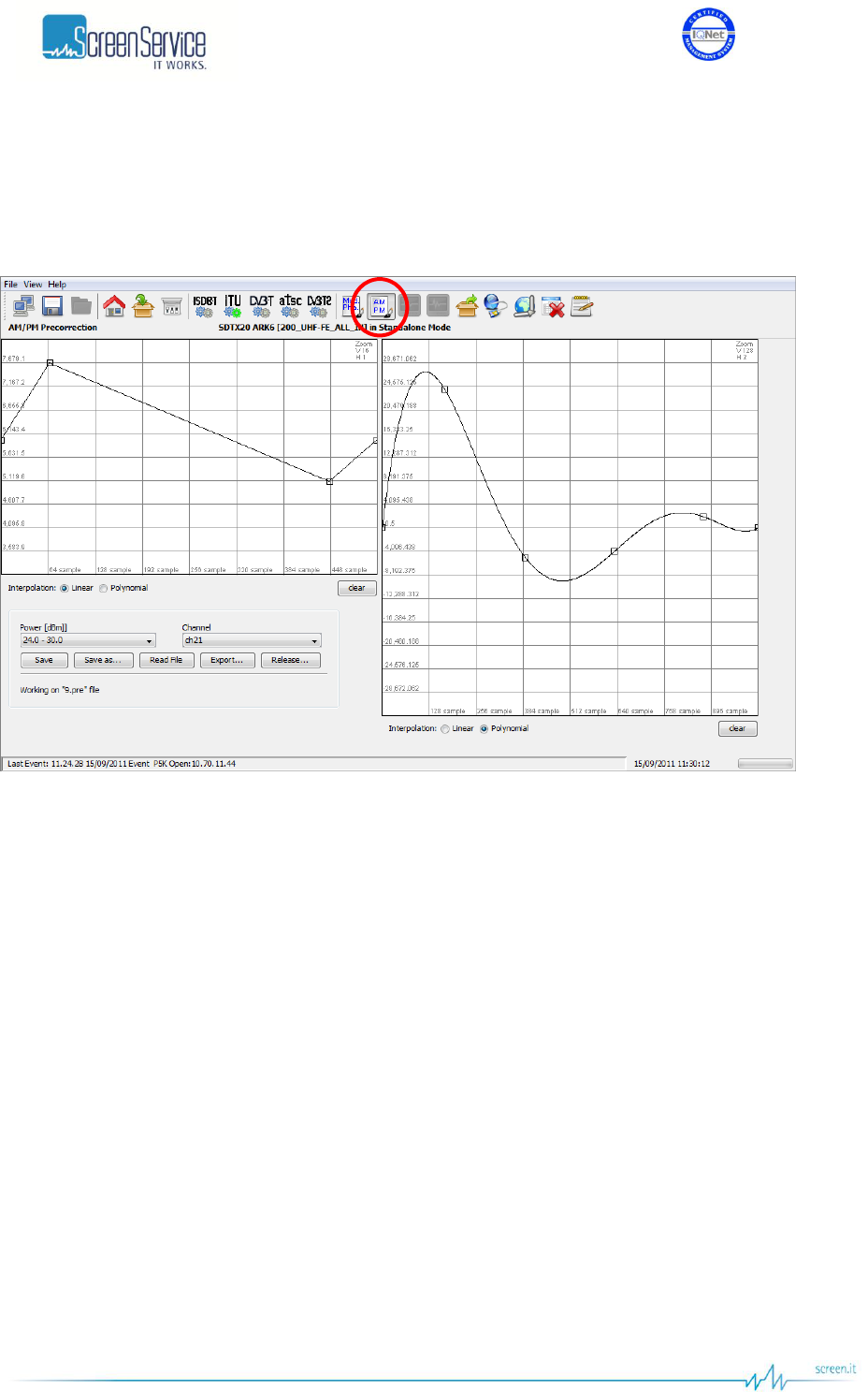
5.8.2 Non Linear Precorrection
Click on AM/PM button icon, highlighted in the next figure, to access the pre-correction window.
Figure 28. AM/PM Precorrection
Two main actions are possible in this section:
AM/AM and AM/PM curve drawing: used to change the AM/PM pre-correction coefficient.
AM/PM pre-correction files management: used to open or save AM/PM pre-correction setting
file.
AM/AM and AM/PM curves are specific for each power range of each output channel.
The two curves are used to calculate the AM/PM pre-correction coefficients. The curves are drawn by
the interpolation of 1024 points referring to the points inserted and using a linear or polynomial
interpolation algorithm.
Knob points can be added with a left-click of the mouse on the grid and deleted with a right-click, drag
and move a point to change the curve.
Each coefficient variation, due to curves change, is saved in the FPGA “runtime” memory registers and
dynamically changes the device’s output.
The tool is prevented to send an “overflowing” amount of data to the device: curve changes will be
applied only when the mouse button is released.
In the module grid, the red curve is used to monitor the current module curve calculating and saving.
The last saved coefficients are locally downloaded from the FPGA runtime memory registers in order to
redraw the curve.

ISO 9001:2000 Cert. N°4500/1
Version 1.1 SDT_ARK6_User_Manual_ENG_vATSC Page 69 of 206
During saving actions one linear pre-correction file is created, the *.dpre file, which contains the digital
coefficients for linear pre-correction filter.
The following buttons allow the management of non linear pre-correction files and the management of
the connection to port 5000:
Save: used to save in the device memory the current curves setting. The previously saved file
will be overwritten except in the event that no files have been saved before; in this case a
dedicated window appears in order to let the user name the new file.
Save as: used to save in the device memory the current curves setting. The previously saved file
will be overwritten with a new name. In the event that no files have been saved before, a new
file will be created.
Read file: used to reload the last saved file.
Export: used to download pre-correction files on the user PC. A browser window allows the
selection of the saving path.
Release: releases the connection in order to allow others remote machines to connect to port
5000 (refer to Connection to port 5000 paragraph).
5.8.3 Port 5000 connection
The connection to port 5000 is performed every time a pre-correction tool is opened through Mod. Pha.
and AM/PM buttons, from Java interface. The pre-correction tool opens and keeps busy the connection
to port 5000 till the connection releasing.
The connection to this port precludes the possibility of:
programming the device;
allowing more than one user, the very same one that is keeping busy the connection, to open
the pre-correction tools,
saving the parameters of the Option sub-menu.
The Release button comes through these limits. It closes the connection to port 5000, close the Mod.
Pha. / AM/PM window and opens the General window. Once clicked the Release buttons and before
quitting the pre-correction tool, three options are provided:
Continue: continue without saving;
Save and Release: save, continue and release the connection;
Cancel: cancel the request of releasing the connection.
Figure 29. Realizing connection
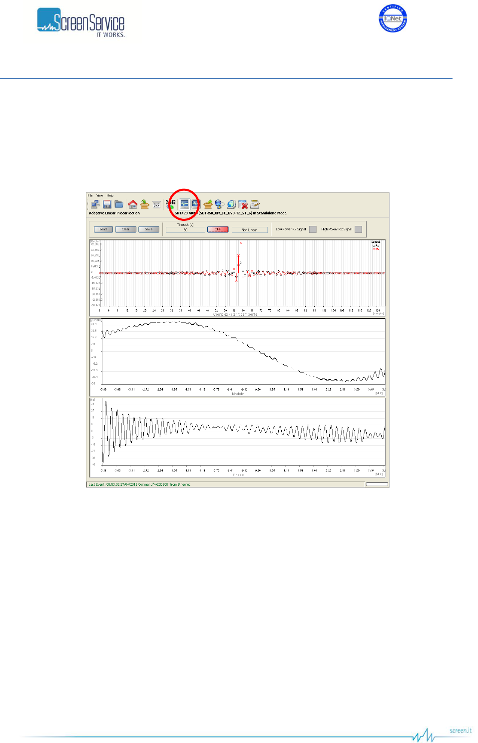
ISO 9001:2000 Cert. N°4500/1
Version 1.1 SDT_ARK6_User_Manual_ENG_vATSC Page 70 of 206
5.9 Adaptive compensation
5.9.1 Linear Adaptive Precorrection
Click on Linear Adaptive Precorrection button, highlighted in the next figure, to access the filter window.
Figure 30. Adaptive Linear Precorrection
This window provides commands and indicators for adaptive filter management and monitor.
The Filter window is organized as follows:
Management panel.
Complex filter coefficients graph.
Module graph.
Phase graph.
In order to enable the adaptive linear precorrection, click on the ON/OFF button.
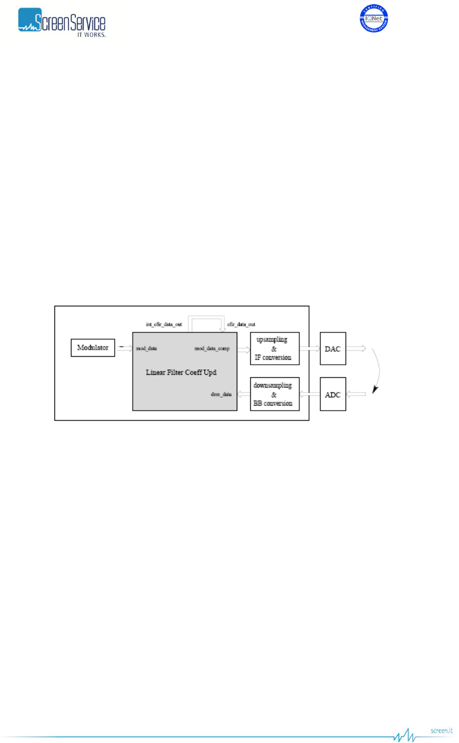
ISO 9001:2000 Cert. N°4500/1
Version 1.1 SDT_ARK6_User_Manual_ENG_vATSC Page 71 of 206
5.9.1.1 Adaptive Filter
The Adaptive Filter provides the ARK6 with an effective adaptive linear compensation.
The developed system is responsible for pre-emptively compensating a DVB-T/T2 signal in order to make
unimportant the contribution of the system transmission section. The signal passes through the
transmission section and re-enters the system as to determine the distortion and the compensating
adaptive filter.
The system is composed of two main blocks: a Power Calculation block and a 128-tap Complex FIR. The
modulated signal, with IQ format and sampled at c frequency, enters both blocks:
Power Calculation block is responsible for estimating the mean power level that will be restored at both
transmitting and receiving sides;
128-tap Complex FIR is responsible for linearly pre-correcting the modulated signal. Filter coefficients
are obtained by estimating the channel between the signal before the transmission section and the
signal reentering the system, after the channel distortion and the A/D conversion.
Figure 31. Adaptive Filter

ISO 9001:2000 Cert. N°4500/1
Version 1.1 SDT_ARK6_User_Manual_ENG_vATSC Page 72 of 206
5.9.1.2 Adaptive Linear Precorrection: Management panel
Table 15. Adaptive Linear Precorrection: Management panel
Box
Parameter / Control
Description
Admitted Ranges / Values
General
Load
Loads filter coefficients from the respective FPGA registers.
General
Clear
Loads flat curve coefficients.
General
Timeout [s]
Once enabled, the adaptive linear compensation has a timeout.
When the timeout is expired, the precorrection is stopped. In order
to continue updating coefficients, click on ON/OFF button.
Fixed to 60 seconds
General
Save
Saves the current adaptive filter coefficients.
General
ON/OFF
Enables the adaptive linear compensation.
ON(Green):Enabled
OFF(Red): Disabled
General
Status
Shows the type of adaptive compensation currently used, if any.
None
Linear
Non Linear
General
Low Power Rx Signal
Indicates that the signal that re-enters the system has a low power.
When this flag is on, the automatic update of the filter coefficients is
stopped.
Red: Alarm On
Grey: Alarm Off
General
High Power Rx Signal
Indicates that the signal that re-enters the system has a high power.
When this flag is on, the automatic update of the filter coefficients is
stopped.
Red: Alarm On
Grey: Alarm Off
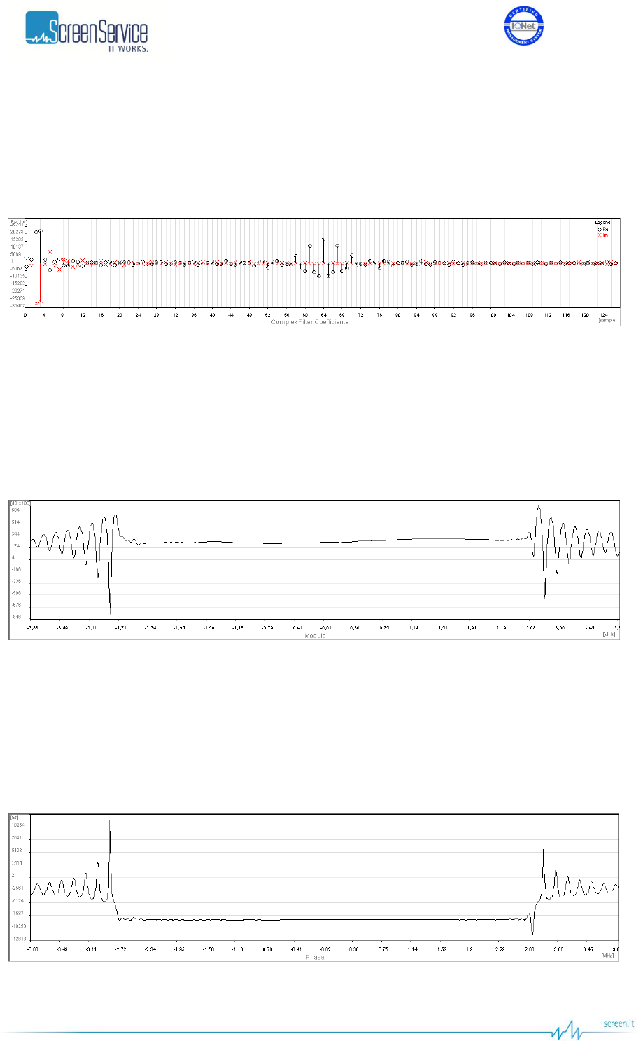
ISO 9001:2000 Cert. N°4500/1
Version 1.1 SDT_ARK6_User_Manual_ENG_vATSC Page 73 of 206
5.9.1.3 Complex Filter coefficients graph
The Complex Filter coefficients graph shows the current coefficients values. The circles indicate the real
part of coefficients; the red crosses indicate the imaginary one.
Figure 32. Filter window: complex filter coefficients graph
5.9.1.4 Module graph
The Module graph shows the actual output signal module according to the complex filer coefficients
applied.
Figure 33. Filter window: module graph
5.9.1.5 Phase graph
The Phase graph shows the actual output signal phase according to the complex filer coefficients
applied.
Figure 34. Filter window: phase graph
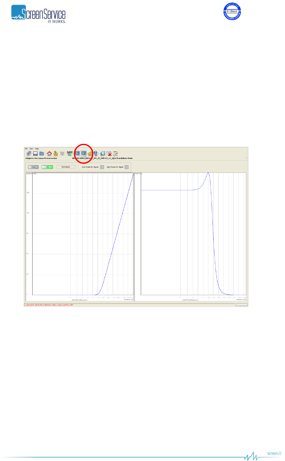
ISO 9001:2000 Cert. N°4500/1
Version 1.1 SDT_ARK6_User_Manual_ENG_vATSC Page 74 of 206
5.9.2 Adaptive Non-Linear Precorrection
The Non Linear Adaptive Filter provides the ARK6-T2 with an effective adaptive non linear
compensation.
The developed system is responsible for pre-emptively compensating the signal in order to make
unimportant the contribution of the intermodulation products due to the power amplifiers.
The signal passes through the power amplifiers and re-enters the system as to determine the distortion
and the compensating adaptive filter.
In order to enable the adaptive non linear precorrection, click on the ON/OFF button.
Figure 35. Adaptive Non Linear Precorrection
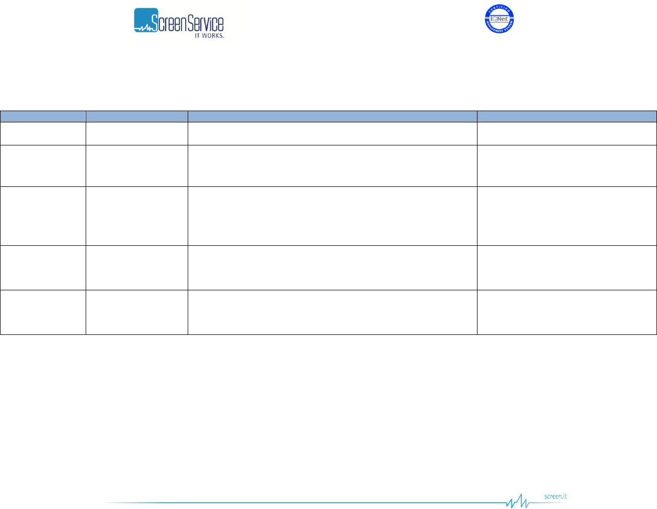
ISO 9001:2000 Cert. N°4500/1
Version 1.1 SDT_ARK6_User_Manual_ENG_vATSC Page 75 of 206
5.9.2.1 Adaptive Non Linear Precorrection: Management panel
Table 16. Adaptive Non Linear Precorrection: Management panel
Box
Parameter / Control
Description
Admitted Ranges / Values
General
Clear
Resets the filter coefficients to zero.
General
ON/OFF
Enables the adaptive non linear compensation.
ON(Green):Enabled
OFF(Red): Disabled
General
Status
Shows the type of adaptive compensation currently used, if any.
None
Linear
Non Linear
General
Low Power Rx Signal
Indicates that the signal that re-enters the system has a low power.
When this flag is on, the automatic update of the filter coefficients is
stopped.
Red: Alarm On
Grey: Alarm Off
General
High Power Rx Signal
Indicates that the signal that re-enters the system has a high power.
When this flag is on, the automatic update of the filter coefficients is
stopped.
Red: Alarm On
Grey: Alarm Off
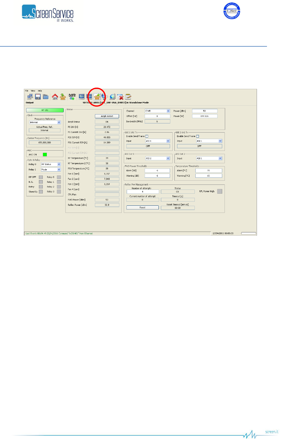
ISO 9001:2000 Cert. N°4500/1
Version 1.1 SDT_ARK6_User_Manual_ENG_vATSC Page 76 of 206
5.10 Output
Click on Output button, highlighted in the next figure, to access the output window.
Figure 36. Output window
Use the Output window to change Ethernet, RF and ASI outputs settings, and to monitor all available
hardware indicators.
ASI Out selectors are used as direct bypass of the specified inputs to ASI OUT HP and ASI OUT LP output
interfaces.

ISO 9001:2000 Cert. N°4500/1
Version 1.1 SDT_ARK6_User_Manual_ENG_vATSC Page 77 of 206
Table 17. Output window
Box
Parameter / Control
Description
Admitted Ranges / Values
General
RF ON / OFF
Output RF signal enabling. The possible output RF signal status are
the following:
ON;
RF OFF: automatic switch off of the output signal (refer to
Amplifier status);
OFF: manual switch off of the output signal.
Green: ON
Green: RF OFF
Red: OFF
Clock
Frequency reference
Frequency reference source selector. This command will select the
reference source used to lock the internal clocks (10 MHz and 1
PPS). When set to internal the 10 MHz clock and 1 PPS generator
runs unlocked. When set to external or GPS the 10 MHz clock is
locked to the source selected and the 1 PPS counter reset is
triggered by the source 1 PPS.
Note: External 10 MHz, 1PPS and GPS shall be connected and
locked when the External and GPS are selected as frequency
references. If the Network Mode is SFN and the Frequency
Reference is set to Internal, the frequency reference is
automatically forced to GPS and the event “Freq Ref Forced: GPS”
is generated Use the Actual Freq. Ref.indicator in order to check
the used reference source.
External
Internal
GPS
Clock
Actual Freq. Ref.
Frequency reference source actually used.
External
Internal
GPS
Centre
Frequency[Hz]
Shows the output centre frequency expressed in Hz.
AGC
AGC ON
AGC status.
Green: ON
Grey: OFF

ISO 9001:2000 Cert. N°4500/1
Version 1.1 SDT_ARK6_User_Manual_ENG_vATSC Page 78 of 206
Box
Parameter / Control
Description
Admitted Ranges / Values
Status
PS 26V [V]
First PSU voltage indicator, expressed in Volt, for SDTx20,
SDTx50, SDTx201 and SDTx501 devices.
Min: 24V
Max: 28V
Status
PS Current 26V [A]
First PSU current indicator, expressed in Ampere, for SDTx20,
SDTx50, SDTx201 and SDTx501 devices.
Max: 8A
Status
PS1 50V [V]
Second PSU voltage indicator, expressed in Volt, for SDTx201 and
SDT501 devices.
Min: 45V
Max: 55V
Status
PS1 Current 50V [A]
Second PSU current indicator, expressed in Ampere, for SDTx201
and SDT501 devices.
Max: 18A
Status
PS2 50V [V]
Third PSU voltage indicator, expressed in Volt, for SDTx501
devices.
Min: 45V
Max: 55V
Status
PS2 Current 50V [A]
Third PSU current indicator, expressed in Ampere, for SDTx501
devices.
Max: 18A
Status
Ampli status
Current amplifier status indicator:
1. ON: the amplifier has been manually set to on and no alarms
or settings switched it off
2. PS Alarm OFF: when an alarm of over current, over voltage or
over power occurs on the second or third Power Supply, the
Amplifier is restarted four times, if the alarm is still on, the
Amplifier is automatically switched off. Single Power Supply
models do not support this status
3. Restart: the amplifier has been automatically restarted due to
an alarm for over current, over voltage or forward power
exceeding the upper limit on the second Power Supply. Single
Power Supply models do not support this status
4. Stand-by OFF: the equipment has been put on Standby mode
and the amplifier has been automatically muted
5. Init: at every amplifier initialization the amp is automatically
switched off.
ON
PS Alarm OFF
Restarting
Stand-by OFF
Init
Alarm OFF
RF OFF
Opto OFF
Change mode
Missing file OFF

ISO 9001:2000 Cert. N°4500/1
Version 1.1 SDT_ARK6_User_Manual_ENG_vATSC Page 79 of 206
Box
Parameter / Control
Description
Admitted Ranges / Values
6. Alarm OFF: an alarm switched off the amplifier
7. RF OFF: amplifier manually set to off
8. Opto OFF: output RF is switched off by an optocoupler
9. Change mode: the amplifier is automatically switched off
during the mode switch (e.g. T1 / T2)
10. Missing file OFF: the amplifier is automatically switched off
because of the lack of *.cdef and *.def files (additional files will
be included in future releases).
11. Loading New Config: the amplifier is automatically switched off
during the loading of new T2 configuration parameters,
12. Reflex Pwr High retry: the output RF stage has been restart
because of the reflex power that has gone over the maximum
threshold.
13. Reflex Pwr Alarm: the maximum number of attempts to restore
the system after a Reflex Power High warning has been
reached, the equipment is in Reflex Power High alarm and the
Amplifier has been automatically switched off.
14. Test Mode: the amplifier is in ON state, but the transmitter is
modulating a test signal instead of the selected input.
15. Start New Firmware: during the loading of a new fw the output
RF is OFF.
16. Restart Mode: a system error occurs and the FPGA fw boot is
forced. During these operations the amplifier is turned OFF.
Loading New Config
Reflex Pwr High Retry
Reflex Pwr High Alarm
Test Mode
Start New Fw
Restart Mode
Status
RF Temperature [°C]
Case temperature indicator (values are expressed in °C).
Status
RF Temperature 2
[°C]
2nd Case temperature indicator (values are expressed in °C).
Only in SDTx201 and SDTx501 versions.
Status
PSU Temperature
PSU temperature indicator (values are expressed in °C).
Status
Fan 1
Fan 1 speed indicator (values are expressed in rpm).
Used in SDTx20, SDTx50, SDTx201 and SDTx501

ISO 9001:2000 Cert. N°4500/1
Version 1.1 SDT_ARK6_User_Manual_ENG_vATSC Page 80 of 206
Box
Parameter / Control
Description
Admitted Ranges / Values
Status
Fan 2
Fan 2 speed indicator (values are expressed in rpm).
Used in SDTx20, SDTx50, SDTx201 and SDTx501.
Status
Fan 3
Fan 3 speed indicator (values are expressed in rpm).
Used in SDTx20, SDTx50, SDTx201 and SDTx501.
Status
Fan 4
Fan 4 speed indicator (values are expressed in rpm).
Used in SDTx501.
Status
CPU Fan
Shows the status of the CPU fan.
There are two types of errors:
Fan fault: fan speed equal to zero;
No Fan: the CPU fan is not connected.
FAN_OK
FAN_FAULT
NO_FAN
Status
FWD Power [dBm]
Output forward power indicator (values are expressed in dBm).
Status
Reflex Power [dBm]
Output reflex power indicator (values are expressed in dBm).
Opto & Relay
Relay 0
Selector of Relay 0 mode.
Alarm: indicator of an alarm
condition
Mode: indicator of operating mode
RF Status: indicator output RF
signal status (on/off)
Opto & Relay
Relay 1
Selector of Relay 1 mode.
Alarm: indicator of an alarm
condition
Mode: indicator of operating mode

ISO 9001:2000 Cert. N°4500/1
Version 1.1 SDT_ARK6_User_Manual_ENG_vATSC Page 81 of 206
Box
Parameter / Control
Description
Admitted Ranges / Values
Opto & Relay
Relay 0…3
Relays status indicators.
Green: Alarm on/Mode A/RF Off
Grey: Alarm off/Mode B/RF On
Opto&Relay
RF OFF
RF Off Opto status indicators.
Opto 0 is a output RF manual on/off switch:
Closed (0): RF off
Opened (1): RF on (default value)
Green: Closed (0)
Grey: Opened (1)
Opto&Relay
N.A.
NOT AVAILABLE
Switch mode Opto status indicators.
When the Switch mode is set to Opto:
Closed (0): Switch to mode B
Opened (1): Switch to mode A
Green: Closed (0)
Grey: Opened (1)
Opto&Relay
N.A.
NOT AVAILABLE
Retry of amplifier alarms status indicators.(only in SDTX 201
version);
Green: Closed (0)
Grey: Opened (1)
Opto&Relay
Stand-By
Stand-by enabling Opto status indicators: .(in version SDTX
20/50/201);
Closed (0): stand-by on
Opened (1): stand-by off
Interlock Opto status indicators.(only in SDTX 501 version);
Closed (0): Interlock off
Opened (1): Interlock on
Stand-by enabling Opto status indicators
Green: Closed (0)
Grey: Opened (1)
Interlock Opto status indicators
Green: Closed (0)
Red: Opened (1)
General
Channel
Output channel.
Channel ranges are device’s definition
dependant.
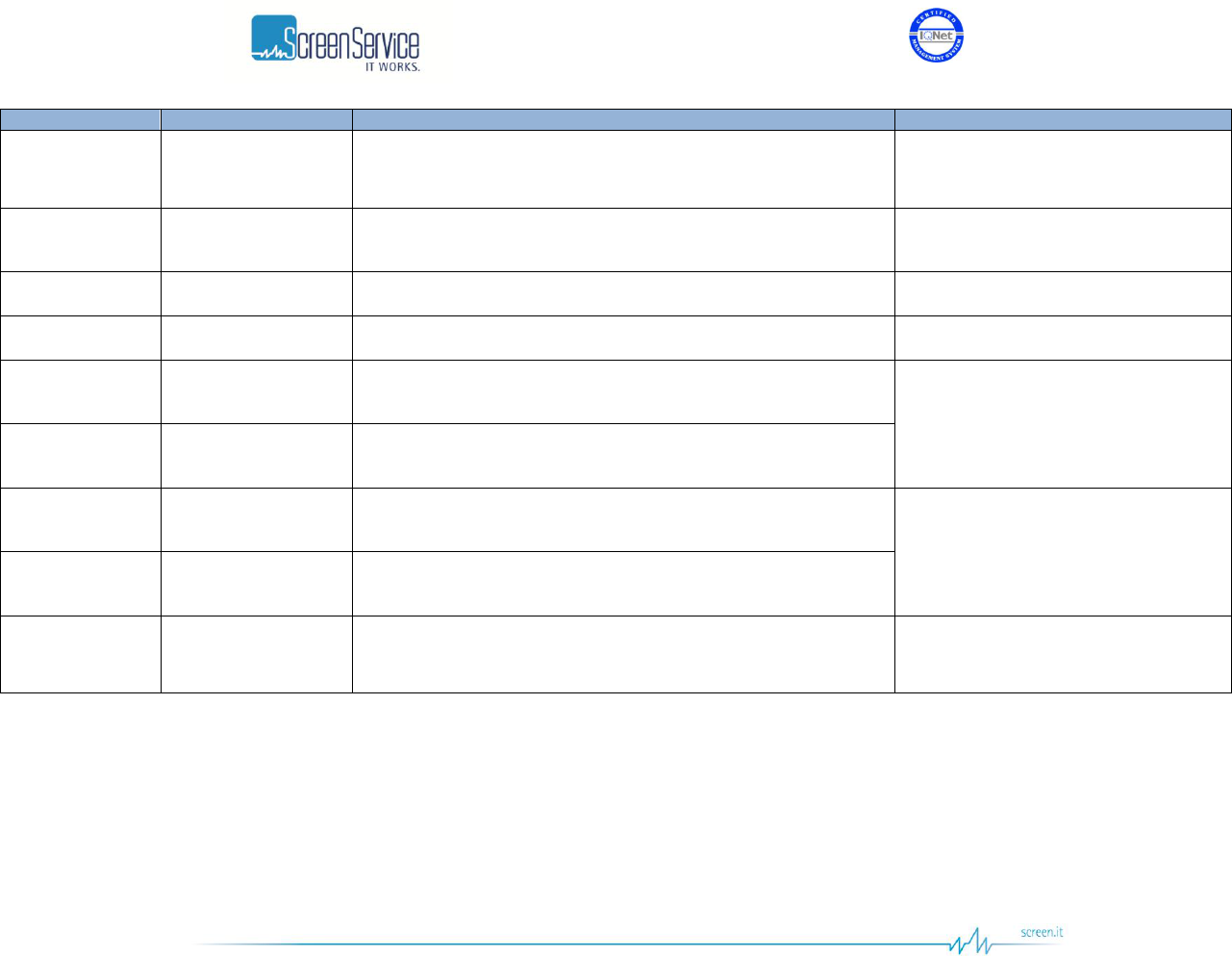
ISO 9001:2000 Cert. N°4500/1
Version 1.1 SDT_ARK6_User_Manual_ENG_vATSC Page 82 of 206
Box
Parameter / Control
Description
Admitted Ranges / Values
General
Offset [Hz]
Output frequency offset (expressed in Hz).
Min: -200 kHz
Max: +200 kHz
General
Power [dBm]
Output power (expressed in dBm).
Output power ranges are device’s
definition dependant.
General
Power [W]
Output power (expressed in W).
General
Bandwidth [MHz]
The output channel bandwidth.
It depends on the device definition.
FWD Power
Thresholds
Warning [dB]
Forward power warning threshold expressed in dB.
Min: -16 dB
Max: 0 dB
FWD Power
Thresholds
Alarm [dB]
Forward power alarm threshold expressed in dB.
Temperature
Thresholds
Warning [°C]
Temperature warning threshold expressed in °C.
Min: 50 °C
Max: 74 °C
Temperature
Thresholds
Alarm [°C]
Temperature alarm threshold expressed in °C.
GbE 2 ch1/2 Tx
Enable send frame
Ethernet channel 1 transmission enabling.
Checked: Enabled
Not checked: Disabled

ISO 9001:2000 Cert. N°4500/1
Version 1.1 SDT_ARK6_User_Manual_ENG_vATSC Page 83 of 206
Box
Parameter / Control
Description
Admitted Ranges / Values
GbE 2 ch1/2 Tx
Input
It selects which TS input shall be re-transmitted on RTP output
channel 1.
This selection is totally independent from the selection of the TS
input to the modulator.
ASI 1
ASI 2
ASI 3
ASI 4
Tuner 1 (if present)
Tuner 2 (if present)
GbE 2 ch1
GbE 2 ch2
GbE ch1/2 Out
Status
Ethernet transmission on channel 1 status indicator.
Resolving IP Addr.
IP not found
No entry
Transmitting data
Transmitting data multicast
No TS input
ON
OFF

ISO 9001:2000 Cert. N°4500/1
Version 1.1 SDT_ARK6_User_Manual_ENG_vATSC Page 84 of 206
Box
Parameter / Control
Description
Admitted Ranges / Values
ASI Out 1/2
Input
Digital modes:
Selects which Transport Stream shall be re-proposed on ASI OUT
HP/LP output.
Analog modes:
Selects which SDI input shall be re-proposed on ASI OUT HP/LP
output.
This selection is totally independent from the selection of the input
of the modulator.
Digital:
o ASI 1
o ASI 2
o ASI 3
o ASI 4
o Tuner 1 (if present)
o Tuner 2 (if present)
o GbE 2 ch1
o GbE 2 ch2
o Rate Ad Out
Analog:
o SDI 1
o SDI 2
o SDI 3
o SDI 4
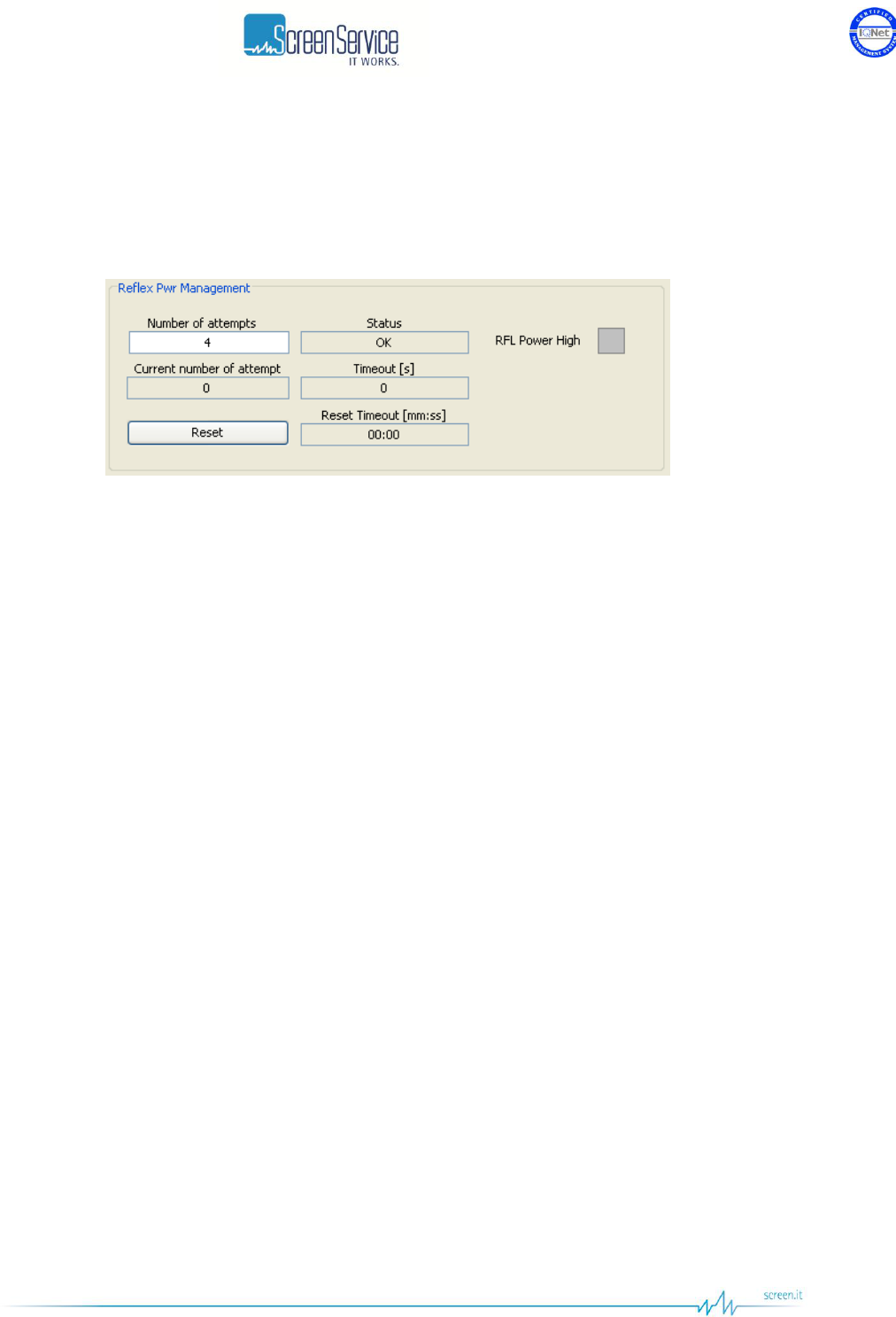
ISO 9001:2000 Cert. N°4500/1
Version 1.1 SDT_ARK6_User_Manual_ENG_vATSC Page 85 of 206
5.10.1 Reflex Power Management
The ARK6 is provided with a reflex power control logic that prevents the amplifier stage from being
permanently damaged.
Figure 37. Reflex Pwr Management
If the output reflex power goes over its alarm threshold, the amplifier stage is automatically shut down
and the system reacts to this situation on the basis of the user selectable “Number of attempts”.
In the case that the user sets a “Number of attempts” equal to zero, the red “RFL Power High” LED is
turned on, the “Status” indicator shows “Alarm” and the amplifier stage is shut down by a “Reflex Pwr
High Alarm”.
In the case that the user sets N as “Number of attempts”, where N is different from zero, a self test is
conducted to determine if the system can be successfully restored. The red “RFL Power High” LED is
turned on, the “Status” indicator shows “Warning” and the amplifier stage is restarted N times. The
delay between two consecutive attempts is fixed to 10 seconds. At every RF ON/OFF the “Ampli status”
indicator will show “Reflex Pwr High Retry”. When the maximum number of attempts is reached, the
“Status” indicator shows “Alarm” and the amplifier stage is shut down by a “Reflex Pwr High Alarm”.
When the “Reflex Pwr High Alarm” is on the amplifier stage is permanently shut down. Once the
operator has carried out the necessary checks, the amplifier shall be manually reset through the button
“Reset”.
If the RFL power control mechanism is in warning state and the RFL power level doesn’t go over the
alarm threshold for 30 minutes, the amplifier stage is automatically reset.
The events associated to the reflex power control logic are the following:
“RFL Power Warning”: the reflex power level is higher than the specification and the “Number
of attempts” is different from zero.
“RFL Power OK”: RFL power goes under the alarm threshold.
“RFL Power Alarm”: RFL power goes over the alarm threshold for N times, where N is the
number of attempts specified in the Output page of the Java GUI.
“RFL RF OFF”: The output RF has been switched off because of either a RFL Power Warning (for
every attempt to restore the system) or a RFL Power Alarm.
“RFL RF ON ”N”: The output RF has been switched on after attempt number “N”.

ISO 9001:2000 Cert. N°4500/1
Version 1.1 SDT_ARK6_User_Manual_ENG_vATSC Page 86 of 206
Table 18. Output window: Reflex Pwr Management
Box
Parameter / Control
Description
Admitted Ranges / Values
Reflex Pwr
Management
Number of attempts
The number of attempts to restore the system after RFL power has
gone over the alarm threshold.
Min: 0
Max: 255
Reflex Pwr
Management
Current number of
attempt
The current number attempt to restore the system.
Min: 0
Max: “Number of attempts”
Reflex Pwr
Management
Status
It shows the current status of the Reflex Power.
OK
Warning
Alarm
Reflex Pwr
Management
RFL Power High
It shows if RFL power goes over the alarm threshold.
Red: RFL power over the alarm
threshold
Grey: RFL power under the alarm
threshold
Reflex Pwr
Management
Timeout [s]
The timeout between two consecutive attempts.
Fixed to 10 seconds
Reflex Pwr
Management
Reset
This button resets the amplifier stage when it is switched off due to
a Reflex Power High alarm.
Reflex Pwr
Management
Reset Timeout [s]
If the RFL power control mechanism is in warning state and the
RFL power level doesn’t go over the alarm threshold for 30 minutes,
the amplifier stage is automatically reset.
Fixed to 30 minutes
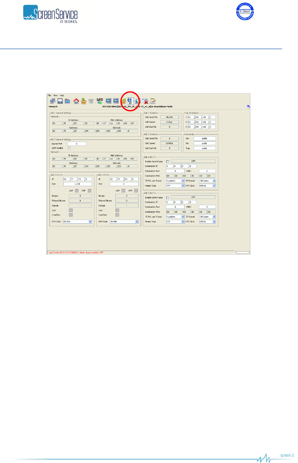
ISO 9001:2000 Cert. N°4500/1
Version 1.1 SDT_ARK6_User_Manual_ENG_vATSC Page 87 of 206
5.11 Network
Click on Network button, highlighted in the next figure, to access the Network management window.
Figure 38. Network window
This window allows the Network management on both PRO-MPEG COP 3 RX and TX sides. It also allows
the monitoring of the board IP and MAC addresses.
Note: The Clock Recovery Function, used in MFN transmissions of received streams on Ethernet channels
1 and/or 2, is based on the timestamps of incoming packets. UDP packets do not contain STS information
therefore it is not allowed using GbE inputs with UDP protocol in MFN transmission mode.

ISO 9001:2000 Cert. N°4500/1
Version 1.1 SDT_ARK6_User_Manual_ENG_vATSC Page 88 of 206
Table 19. Network window
Box
Parameter / Control
Description
Admitted Ranges / Values
GbE 1/2 General
Settings /
Network
IP address
Gbe port 1 / 2 IP address.
GbE 1/2 General
Settings /
Network
MAC address
Gbe port 1 / 2 MAC address.
GbE 1/2 General
Settings /
Network
Gateway
Gbe port 1 / 2 Gateway address.
GbE 1/2 General
Settings /
Network
Netmask
Gbe port 1 / 2 Netmask.
GbE 2 General
Settings /
Network
IGMP Enable
Enables the IGMP protocol.
Checked: Enabled
Not checked: Disabled
GbE 2 General
Settings /
Network
Source Port
Board transmitting port.
Min: 0
Max: 65.535
Trap IP address
1/2/3
Manager Trap 1/2/3 IP addresses.
GbE 2 ch1/2 Rx
IP Address
Channel 1/2 receiving IP address.
GbE 2 ch1/2 Rx
Port
Channel 1/2 receiving port.
Min: 0
Max: 65,535

ISO 9001:2000 Cert. N°4500/1
Version 1.1 SDT_ARK6_User_Manual_ENG_vATSC Page 89 of 206
Box
Parameter / Control
Description
Admitted Ranges / Values
GbE 2 ch1/2 Rx
Protocol
Ethernet input packets protocol.
UDP/RTP:
o Green: Detected
o Grey: Not detected
GbE 2 ch1/2 Rx
Bitrate
Bit-rate of TS from Ethernet input.
GbE 2 ch1/2 Rx
Filtered bitrate
Bit-rate actually used by the modulator.
Zero when the input is not selected
Equal to the total bit-rate, when
Delete Null Packets disabled
Less than total bit-rate, when Delete
Null Packets enabled
GbE 2 ch1/2 Rx
Format
Received transmission format.
188 Bytes
204 Bytes
GbE 2 ch1/2 Rx
Lock
Ethernet input lock status indicator. The input Transport Stream is
locked when no more than two consecutive Sync Byte are missed.
Green: Lock
Grey: Not locked
GbE 2 ch1/2 Rx
Overflow
Input GbE overflow alarm status. This alarm condition occurs when
the input bit-rate exceeds the capability of the modulation (Ref. to
ETSI EN 302 755).
Red: Alarm on
Grey: Alarm off
GbE 2 ch1/2 Rx
RTP Clock
RTP packets source clock reference.
90 kHz
27 MHz
GbE 1 / 2 Statistic
GbE Good Pck
Total amount of frames delivered to the higher-level protocol.
GbE 1 / 2 Statistic
GbE Speed
Ethernet connection speed. No duplex information is provided.
10 Mbit//s
100 Mbit//s
1 Gbit/s

ISO 9001:2000 Cert. N°4500/1
Version 1.1 SDT_ARK6_User_Manual_ENG_vATSC Page 90 of 206
Box
Parameter / Control
Description
Admitted Ranges / Values
GbE 1 / 2 Statistic
GbE Bad Pck
The number of inbound packets that contained errors.
Community
Get
Read community setting.
Community
Set
Set community setting.
Community
Trap
Trap community setting.
GbE 2 ch1/2 Tx
Enable send frame
Channel 1/2 Ethernet transmission enabling.
Checked: Enabled
Not checked: Disabled
GbE 2 ch1/2 Tx
IP
Channel 1/2 Ethernet transmission IP address.
GbE 2 ch1/2 Tx
Port
Port used for RTP/UDP data transmission
Min: 0
Max: 65,535
GbE 2 ch1/2 Tx
Status
Ethernet transmission on channel 1/2 status indicator.
Resolving IP Addr.
IP not found
No entry
Transmitting data
Transmitting data multicast
ON
OFF
GbE 2 ch1/2 Tx
Destination MAC
Destination MAC address.
GbE 2 ch1/2 Tx
SSRC
SSRC identifier of the RTP transmission on channel ½.

ISO 9001:2000 Cert. N°4500/1
Version 1.1 SDT_ARK6_User_Manual_ENG_vATSC Page 91 of 206
Box
Parameter / Control
Description
Admitted Ranges / Values
GbE 2 ch1/2 Tx
TS Pck per Frame
Number of packets per frame.
Min: 1
Max: 7
GbE 2 ch1/2 Tx
Frame type
Transmission protocol selector.
RTP
UDP
GbE 2 ch1/2 Tx
TS Format
Transmission format.
188 Bytes
204 Bytes
GbE 2 ch1/2 Tx
RTP Clock
RTP packets clock reference.
90 kHz
27 MHz
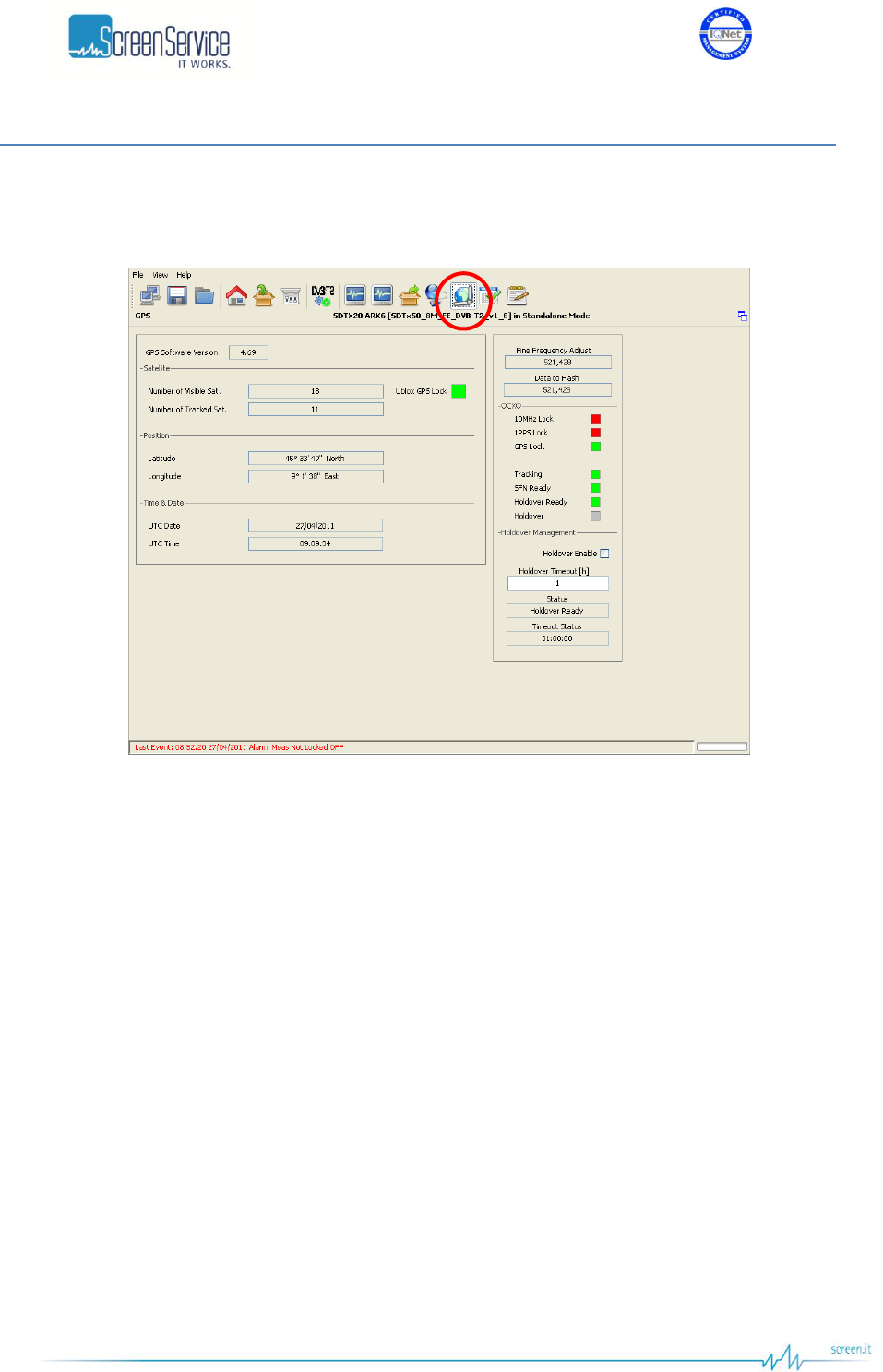
ISO 9001:2000 Cert. N°4500/1
Version 1.1 SDT_ARK6_User_Manual_ENG_vATSC Page 92 of 206
5.12 GPS
Click on GPS button, highlighted in the next figure, to access the GPS received statistics window.
Figure 39. GPS window

ISO 9001:2000 Cert. N°4500/1
Version 1.1 SDT_ARK6_User_Manual_ENG_vATSC Page 93 of 206
Table 20. GPS window
Box
Parameter / Control
Description
Admitted Ranges / Values
General
GPS Software
Version
The firmware version of the GPS module.
Satellite
#Number of Visible
sat
Number of visible GPS satellites indicator.
Satellite
#Number of Tracked
sat
Number of tracked GPS satellites indicator.
Satellite
Ublox GPS Lock
Ublox GPS Lock status. This LED shows the GPS lock status
derived from live data provided by the GPS receiver through a
proprietary protocol.
Green: GPS Locked
Red: GPS Not Locked
Position
Latitude (°)
Site latitude expressed in degrees.
Position
Longitude (°)
Site longitude expressed in degrees.
Date & Time
UTC Time
Current time indicator.
Each GPS satellite has an atomic clock and continually transmits
messages containing the current time and date at the start of the
message sent by the GPS itself.
Date & Time
UTC Date
Current date indicator.
Each GPS satellite has an atomic clock and continually transmits
messages containing the current time and date at the start of the
message send by the GPS itself.

ISO 9001:2000 Cert. N°4500/1
Version 1.1 SDT_ARK6_User_Manual_ENG_vATSC Page 94 of 206
5.12.1 Holdover Management
The ARK6 includes a holdover function provided by a higher grade Oven-Controlled Crystal Oscillator.
Figure 40. Holdover Management
The ARK6 is equipped with an internal OCXO for improved phase noise and stability. The system is
provided with internal 10MHz and 1PPS signals which are disciplined to the GPS time signal or to the
10MHz and 1PPS external references. The stability of internal frequency and phase is assured by the
highly stable OCXO. If the satellites signal, from the GPS receiver, or the external reference sources are
completely lost, the Holdover mode enables the unit to keep working with internal 10MHz and 1PPS for
the duration of the Holdover Timeout, with very low drift over time. If the timeout period elapses prior
to regain the lock of the selected clock reference source and the Holdover function is enabled, the alarm
“Holdover” is raised.
Depending on the conditions, the Holdover function can work in one of the following state:
1. Holdover OFF
Condition 1: the clock reference is changed and the OCXO is not locked yet.
Condition 2: the input clock reference is not present.
Associated event: “Holdover OFF”-
2. SFN Ready
Condition: the OCXO is locked to the selected frequency reference and the
system is waiting for the OCXO stabilization.
Associated event: “Holdover SFN Ready”.
3. Holdover Ready
Condition 1: the OCXO is stable and the Holdover function is now available.
Condition 2: the system quit the Holdover mode because the OCXO regain the
lock to the selected clock reference.
Associated event: “Holdover Ready”.

ISO 9001:2000 Cert. N°4500/1
Version 1.1 SDT_ARK6_User_Manual_ENG_vATSC Page 95 of 206
4. Holdover ON
Condition: if the OCXO is no more locked to the selected frequency reference
and the Holdover function is enabled and available, the equipment enters into
holdover mode.
Associated event: “Holdover ON”.
5. Holdover TMO Expired
Condition: the Holdover state is “Holdover ON” (the function is enabled) and
the Holdover timeout period elapses prior to regain the lock of the selected
clock reference source.
Associated event: “Holdover TMO Expired”.

ISO 9001:2000 Cert. N°4500/1
Version 1.1 SDT_ARK6_User_Manual_ENG_vATSC Page 96 of 206
Table 21. GPS window: Holdover Management
Box
Parameter / Control
Description
Admitted Ranges / Values
General
Fine Frequency
Adjust
Internal frequency reference fine tuning setting. It is possible to
increase and decrease the frequency offset of the OCXO with
reference to the 10MHz clock by 1/21 Hz steps using the Fine
Frequency Adjust. This field is accessible only if the Frequency
Reference selector is set to Internal
Min: 0
Max: 1,048,575
General
Data to Flash
The saved DAC value during the stabilization process of the OCXO.
It represents the last saved frequency offset of the OCXO,
expressed in 1/21 Hz steps, with respect to the selected frequency
reference source.
Using External or GPS as frequency reference, the last saved Data
to Flash value will be:
retained after a software reset;
reinitialized to zero after a hardware reset (unit powered
down and powered back up).
Using Internal as frequency reference, the last saved Data to Flash
value will be overwritten with the Fine Frequency Adjust value after:
a software reset;
an hardware reset;
setting to Internal the frequency reference.
Min: 0
Max: 1,048,575
OCXO
10MHz Lock
Shows the lock status of the OCXO to the external 10MHz
reference.
Red: Not Locked
Green: Locked
OCXO
1PPS lock
Shows the lock status of the OCXO to the external 1PPS reference.
Red: Not Locked
Green: Locked

ISO 9001:2000 Cert. N°4500/1
Version 1.1 SDT_ARK6_User_Manual_ENG_vATSC Page 97 of 206
Box
Parameter / Control
Description
Admitted Ranges / Values
OCXO
GPS Lock
OCXO locked to the external GPS reference.
Green: Locked
Grey: Not Locked
OCXO
Tracking
It shows whenever the OCXO is not locked to the selected
frequency reference or not.
Green: Locked
Grey: Not Locked
OCXO
SFN Ready
It shows whenever the OCXO is locked to the selected frequency
reference and the system is waiting for the OCXO stabilization or
not.
Green: SFN Ready
Grey: SFN Not Ready
OCXO
Holdover Ready
It shows whenever the Holdover function is available or not.
Green: Holdover Ready
Grey: Holdover Not Ready
OCXO
Holdover
It notifies that the equipment entered into Holdover mode
Green: Holdover On
Grey: Holdover Off
Holdover
Management
Holdover Enable
Enables the Holdover mechanism.
Checked: Enabled
Not checked: Disabled
Holdover
Management
Holdover Timeout [h]
Sets the timeout of the Holdover in hour.
Min: 0 h
Max: 24 h
Holdover
Management
Status
The status of the Holdover mechanism.
OFF
SFN Ready
Ready
ON
Expired
ISO 9001:2000 Cert. N°4500/1
Version 1.1 SDT_ARK6_User_Manual_ENG_vATSC Page 98 of 206
Box
Parameter / Control
Description
Admitted Ranges / Values
Holdover
Management
Timeout Status
The countdown of the Holdover timeout.
Min:00:00:00
Max: “Holdover Timeout [s]”
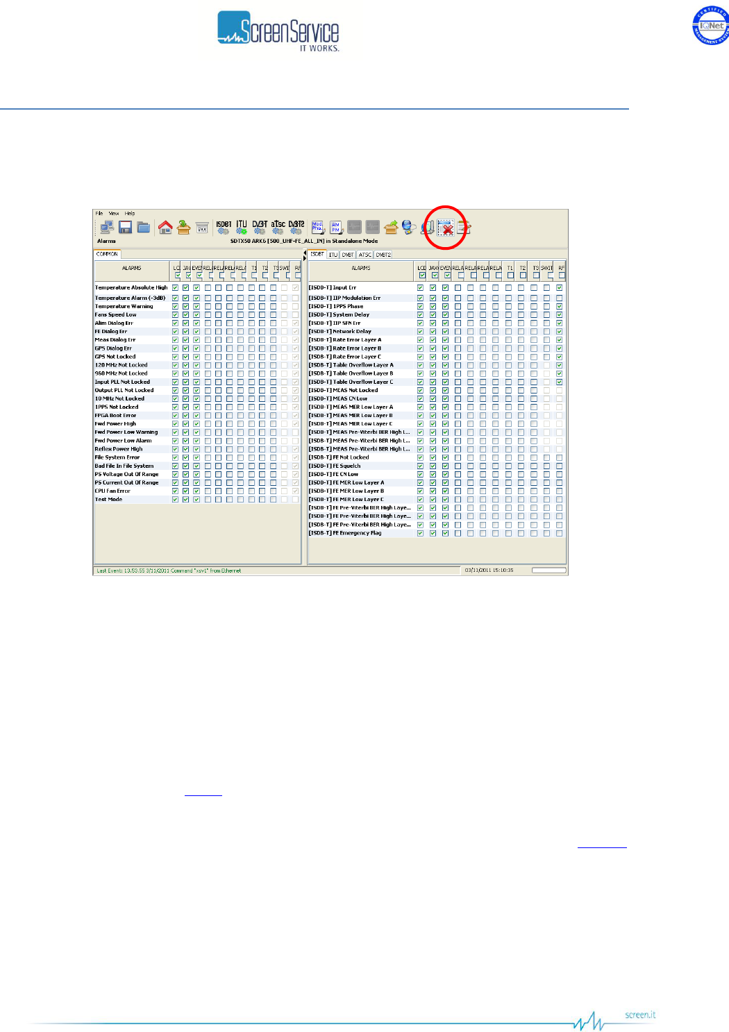
ISO 9001:2000 Cert. N°4500/1
Version 1.1 SDT_ARK6_User_Manual_ENG_vATSC Page 99 of 206
5.13 Alarms
Click on Alarms button, highlighted in the next figure, to access the alarms management window.
Figure 41. Alarms window
The Alarms window allows the setting of alarm masks and the monitoring of alarms status. Use alarm
masks to select how and which alarm have to be notified.
Masks are organized in columns. The twelve columns represent twelve destinations of each alarm
notification:
GUI: the selected alarms status is notified on the Java alarm page icon.
LCD: the selected alarms status is notified on LCD display lighting the alarm button and listing
the alarms in the Alarms menu.
Event: the selected alarms status generate an alarm event that will be logged in the event
memory (refer to Events paragraph).
RELAY0…3: the selected alarms switch on the corresponding relay.
T1…T3: the selected alarms generate the corresponding trap messages (refer to Network
paragraph to set destination IP addresses).
RF: the selected alarms switch off the output RF signal. The RF mask is almost entirely fixed in
order to avoid device damages or malfunctioning.
SWITCH: the selected alarms trigger the automatic input switching, if enabled.
In the Alarms window, when an alarm condition occurs, the relative alarm is red highlighted. The Total
check boxes enable all alarms-to-masks associations.

ISO 9001:2000 Cert. N°4500/1
Version 1.1 SDT_ARK6_User_Manual_ENG_vATSC Page 100 of 206
Table 22. Alarms window
Alarm
Description and limitations
Troubleshooting
Mode(2)
RF mask (1)
Temperature
Absolute High
Case temperature over 75°C, the maximum
endurable limit.
Check alarm and warning thresholds
Lower the output power to decrease internal
temperature
Check the device airflow
Check fans
C
1
Temperature Alarm (-
3dB)
Temperature level goes over the alarm
threshold.
The output power is consequently lowered by
3 dB (always within the admitted power
range).
C
0
Temperature Warning
Temperature level goes over the warning
threshold.
C
0
Fans Speed Low
One of the fans speed is under the minimum
speed level (2,000 rpm).
Check fans connections
Verify that fans are not damaged; in this case
substitute them. The substitution can be
performed during device normal operations
C
0
Alim Dialog Err
Communication errors between the main
board and the power supply board.
Hardware fault
C
1
FE Dialog Err
Communication errors between the main
board and the Front-End board.
Hardware fault
C
1
Meas Dialog Err
Communication errors between the main
board and the Measure board.
Hardware fault
C
1

ISO 9001:2000 Cert. N°4500/1
Version 1.1 SDT_ARK6_User_Manual_ENG_vATSC Page 101 of 206
Alarm
Description and limitations
Troubleshooting
Mode(2)
RF mask (1)
GPS Not Locked
GPS signal is not locked by either the OCXO
or the GPS receiver.
The monitoring of this alarm is disabled when
GPS is not used as clock reference or when
the GPS Communication Error is raised.
Check cable and GPS antenna connections
Hardware fault
C
1
GPS Dialog Err
Communication errors between main board
and
GPS board.
The monitoring of this alarm is disabled when
GPS is not used as clock reference.
Hardware fault
C
1
120MHz Not Locked
120 MHz is not locked.
The monitoring of this alarm is disabled when
the Signal 10 MHz Not Locked alarm is raised
or when GPS is used as clock reference and
GPS alarm (GPS Not Locked, GPS Dialog
Err) is raised.
In SFN configuration, when selected TS input
or MIP are not detected, 120 MHz oscillator
can lose the lock
Hardware fault
C
1
960MHz Not Locked
960 MHz is not locked.
Hardware fault
C
1
Input PLL Not Locked
Input PLL not locked alarm
Hardware fault
C
1
Output PLL Not
Locked
Output PLL not locked alarm
Hardware fault
C
1
Bad File In File
System
One or more of the following files are not
present in the File System:
Check files list
C
1
ISO 9001:2000 Cert. N°4500/1
Version 1.1 SDT_ARK6_User_Manual_ENG_vATSC Page 102 of 206
Alarm
Description and limitations
Troubleshooting
Mode(2)
RF mask (1)
*.cfg
*.drlin
*.ochf
*.fpga6
*.snmp
*.htm
*.jar
*.def
*.pwr2
*.sav
*.cdef2
*.gpsf
Reload the file system
10MHz Not Locked
10 MHz is not locked.
If the frequency reference is Internal: OCXO
fault
If the frequency reference is External:
o OCXO fault
o Lack of external 10 MHz
o Hardware fault
If the frequency reference is GPS:
o Check GPS alarms
o OCXO fault
o Hardware fault
C
1

ISO 9001:2000 Cert. N°4500/1
Version 1.1 SDT_ARK6_User_Manual_ENG_vATSC Page 103 of 206
Alarm
Description and limitations
Troubleshooting
Mode(2)
RF mask (1)
1PPS Not Locked
1PPS is not locked to the selected frequency
reference.
If the frequency reference is Internal: OCXO
fault
If the frequency reference is External:
o OCXO fault
o Lack of external 1PPS
o Hardware fault
If the frequency reference is GPS:
o Check GPS alarms
o OCXO fault
o Hardware fault
C
1
FPGA Boot alarm
FPGA boot has not been successfully
completed.
Restart the machine
Reload the file system
C
1
Forward Power High
FWD power goes over the maximum
endurable limit.
Hardware fault
C
1
Forward Power Low
Warning
FWD power level goes over the warning
threshold.
Check alarm and warning thresholds
At every amplifier initialization the FWD power
alarm and warning are temporary on
Amplifier is not properly working, hardware fault
C
0
Forward Power Low
Alarm
FWD power level goes over the alarm
threshold.
C
0
Reflex Power High
RFL power goes over the set power -9 dB.
Check the RF output for disconnection or
wrong impendence adaptation
C
0
File System Error
File System loading error.
File system partition damage
C
1

ISO 9001:2000 Cert. N°4500/1
Version 1.1 SDT_ARK6_User_Manual_ENG_vATSC Page 104 of 206
Alarm
Description and limitations
Troubleshooting
Mode(2)
RF mask (1)
PS Voltage Out Of
Range
Power Supply voltage out of range. This
alarm is risen when at least one of the
following conditions is met:
PS 26V < 24V or > 28V
PS1/PS2 50V < 45V or > 55V
Hardware fault
C
1
PS Current Out Of
Range
Power Supply current out of range. This alarm
is risen when at least one of the following
conditions is met:
PS Current 26V > 8A
PS1/PS2 Current 50V> 18A
Hardware fault
C
1
CPU Fan Error
CPU fan speed equal to zero or CPU fan not
connected.
Check fan connection
C
1
Test Mode
The equipment is generating a test signal.
Disable the test signal
C
0
FE S2 Not Locked
Lock state indicator of the satellite feed.
Check input signal and cable
C
X
FE S2 S/N Low
Front-End S/N measure goes over the alarm
threshold.
Check input signal and cable
C
X
FE S2 BER High
Front-End BER measure goes over the alarm
threshold.
Check input signal and cable
C
X
FE S2 Global Alarm
C
X
[DVB-T2] No Input
Selected TS input not locked.
Check input cable
Check input statistics
T2
X

ISO 9001:2000 Cert. N°4500/1
Version 1.1 SDT_ARK6_User_Manual_ENG_vATSC Page 105 of 206
Alarm
Description and limitations
Troubleshooting
Mode(2)
RF mask (1)
[DVB-T2] Input
Overflow
Selected TS input overflow.
Check the capability of the current modulation
scheme
Check if the configuration has been loaded
T2
X
[DVB-T2] FE Not
Locked
Logical AND between FE TS lock and FE
demodulator ready (SyncStat equals to 6).
Check input signal and cable
T2
X
[DVB-T2] FE Squelch
Front-End Squelch level goes over the alarm
threshold.
Check input signal and cable
T2
X
[DVB-T2] FE Pre
LDPC BER High
Front-End Pre LDPC BER goes over the
alarm threshold.
Check input signal and cable
T2
X
[DVB-T2] FE SNR
Low
Front-End SNR goes under the alarm
threshold.
Check input signal and cable
T2
X
[DVB-T2] FE MER
Low
Front-End MER goes under the alarm
threshold.
Check input signal and cable
T2
X
[DVB-T2] FE Signal
Quality Low
Front-End Signal Quality goes under the
alarm threshold.
Check input signal and cable
T2
X
[DVB-T2] MEAS Not
Locked
Logical AND between Meas TS lock and
Meas demodulator ready (SyncStat equals to
6).
Check the configuration
Check if the configuration has been loaded
T2
0
[DVB-T2] MEAS Pre
LDPC BER High
Measure Pre LDPC BER goes over the alarm
threshold.
Check the configuration
Check if the configuration has been loaded
T2
0
[DVB-T2] MEAS SNR
Low
Measure SNR goes under the alarm
threshold.
Check the configuration
Check if the configuration has been loaded
T2
0

ISO 9001:2000 Cert. N°4500/1
Version 1.1 SDT_ARK6_User_Manual_ENG_vATSC Page 106 of 206
Alarm
Description and limitations
Troubleshooting
Mode(2)
RF mask (1)
[DVB-T2] MEAS MER
Low
Measure MER goes under the alarm
threshold.
Check the configuration
Check if the configuration has been loaded
T2
0
[DVB-T2] MEAS
Signal Quality Low
Measure Signal Quality goes under the alarm
threshold.
Check the configuration
Check if the configuration has been loaded
T2
0
[DVB-T2] T2-MI Err
The logical OR of the following conditions:
CRC of incoming T2-MI pkts is not
correct.
The Network mode is SFN but the
selected Parameters Source is not T2-MI
Parameters.
Check input signal
T2
1
[DVB-T2] T2-MIP Err
T2-MIP errors
Check input signal
T2
X
[DVB-T2] Holdover
An alarm that is raised when the Holdover
function is enabled and the set timeout period
elapsed prior to regain the lock of the
frequency reference.
Check input frequency reference source.
T2
X
[DVB-T2] PPS Phase
1PPS is not lock to a source reference
common to the network. This alarm is
available only when the frequency reference
is external.
Check 1PPS
Hardware fault
T2
X
[DVB-T2]
Configuration Not
Loaded
Some configuration parameters have been
changed and the current configuration has not
been loaded yet.
Load the configuration through the Load Config
button in DVB-T2 Processing window
T2
X
[DVB-T2] FE LDPC
Mean Err
RF input LDPC iteration per minute goes over
the alarm threshold.
Check input signal
T2
X

ISO 9001:2000 Cert. N°4500/1
Version 1.1 SDT_ARK6_User_Manual_ENG_vATSC Page 107 of 206
Alarm
Description and limitations
Troubleshooting
Mode(2)
RF mask (1)
[DVB-T2] MEAS
LDPC Mean Err
RF output LDPC iteration per minute goes
over the alarm threshold.
Check input signal
T2
0
[DVB-T2] SFN Alarm
The logical OR of the following conditions:
T2-MI Timestamp error.
T2-MI Timestamp wrong CRC.
T2-MI Timestamp not present.
The Holdover status is either OFF or
TMO Expired.
The monitoring of this alarm is disabled when
the [DVB-T2] T2-MI Err alarm is on and when
the Network mode is MFN.
Check input signal
T2
X
[DVB-T] Input Not
present Alarm
Seamless improper working warning
One or both Seamless logic input of the
current mode isn’t locked.
This alarm is enable only in Tx DVBT mode
Check connection status of physical input
associated to logic input
Check type and source of input associated to
logic input
Hardware fault
T
0

ISO 9001:2000 Cert. N°4500/1
Version 1.1 SDT_ARK6_User_Manual_ENG_vATSC Page 108 of 206
Alarm
Description and limitations
Troubleshooting
Mode(2)
RF mask (1)
[DVB-T] Input Not
valid Alarm
Seamless improper working warning
An error has been detected on Logical
seamless input. The possible errors which
may be detected on input are:
PAT error
MIP error
TS synchronization
Packet jitter
Transport error
ASI word error
When the alarm is detected, an event (if event
mask is enabled on alarm mask) shows the
cause of the error. The cause shown is only
one, and it is the heaviest one. The priority in
the errors is as previously listed (the heaviest
error cause is the one listed in the bottom of
the list, and so on).
Check input signal
Check cable connection status
Hardware fault
T
0
[DVB-T] MIP Delay
High
Seamless improper working warning
This alarm is high when the MIP in one of the
seamless inputs of the current mode, is not in
its expected position. This can be caused by a
too high delay on the input.
Check cable connections
Check Network delay
Hardware Fault
T
0
[DVB-T] No Input
Selected TS input not locked. It could be
either ASI or Tuner input.
Check input cable
Check input statistics
T
X
[DVB-T] Input
Overflow
Selected TS input overflow.
Check the capability of the current modulation
scheme
T
X

ISO 9001:2000 Cert. N°4500/1
Version 1.1 SDT_ARK6_User_Manual_ENG_vATSC Page 109 of 206
Alarm
Description and limitations
Troubleshooting
Mode(2)
RF mask (1)
[DVB-T] MIP Err
MIP packets missing. This alarm’s RF OFF
mask should always be enabled.
Alarm raising limitations:
The monitoring of this alarm is enabled only
when the device has SFN modulation
enabled.
The monitoring of this alarm is disabled when
a No Input alarm is raised.
Check input signal
T
1
[DVB-T] PPS Phase
1PPS is not lock to a source reference
common to the network. This alarm is
available only when the frequency reference
is external.
Check 1PPS
Hardware fault
T
X
[DVB-T] SFN Alarm
Seamless improper working warning
This alarm is high when the Network delay is
greater than the Maximum delay or when the
internal counter, used to compute the System
delay is not locked to 1PPS. This alarm shall
always be enabled in the RF Off alarm mask.
Check cable connections
Check Network delay
Check 1PPS
Hardware Fault
T
1
[DVB-T] FE Not
Locked
Logical AND between FE TS lock and FE
demodulator ready (SyncStat equals to 6).
Check input signal and cable
T
X
[DVB-T] FE Squelch
Front-End Squelch level goes over the alarm
threshold.
Check input signal and cable
T
X
[DVB-T] FE Pre
Viterbi BER High
Front-End Pre Viterbi BER goes over the
alarm threshold.
Check input signal and cable
T
X
[DVB-T] FE SNR Low
Front-End SNR goes under the alarm
threshold.
Check input signal and cable
T
X
ISO 9001:2000 Cert. N°4500/1
Version 1.1 SDT_ARK6_User_Manual_ENG_vATSC Page 110 of 206
Alarm
Description and limitations
Troubleshooting
Mode(2)
RF mask (1)
[DVB-T] FE MER Low
Front-End MER goes under the alarm
threshold.
Check input signal and cable
T
X
[DVB-T] FE Signal
Quality Low
Front-End Signal Quality goes under the
alarm threshold.
Check input signal and cable
T
X
[DVB-T] MEAS Not
Locked
Logical AND between Meas TS lock and
Meas demodulator ready (SyncStat equals to
6).
Check the configuration
Check if the configuration has been loaded
T
0
[DVB-T] MEAS Pre
Viterbi BER High
Measure Pre Viterbi BER goes over the alarm
threshold.
Check the configuration
Check if the configuration has been loaded
T
0
[DVB-T] MEAS SNR
Low
Measure SNR goes under the alarm
threshold.
Check the configuration
Check if the configuration has been loaded
T
0
[DVB-T] MEAS MER
Low
Measure MER goes under the alarm
threshold.
Check the configuration
Check if the configuration has been loaded
T
0
[DVB-T] MEAS Signal
Quality Low
Measure Signal Quality goes under the alarm
threshold.
Check the configuration
Check if the configuration has been loaded
T
0
[DVB-T] Holdover
An alarm that is raised when the Holdover
function is enabled and the set timeout period
elapsed prior to regain the lock of the
frequency reference.
Check input frequency reference source.
T
X
[ITU] No video input
Selected input not locked.
Check input cable
Check input statistics
ITU
X

ISO 9001:2000 Cert. N°4500/1
Version 1.1 SDT_ARK6_User_Manual_ENG_vATSC Page 111 of 206
Alarm
Description and limitations
Troubleshooting
Mode(2)
RF mask (1)
[ITU] Input Wrong
Standard
Selected Input video standard (525 or 625
lines) not compatible with the ARK6 definition
standard.
Check input format
Check input statistics
ITU
X
[ITU] Holdover
An alarm that is raised when the Holdover
function is enabled and the set timeout period
elapsed prior to regain the lock of the
frequency reference.
Check input frequency reference source.
ITU
X
[ISDB-T] Input Error
ISDB-T
X
[ISDB-T] IIP
Modulation Error
ISDB-T
X
[ISDB-T] 1PPS Phase
1PPS is not lock to a common reference of
the network. This alarm is available only when
the frequency reference is external.
Check 1PPS
Hardware fault
ISDB-T
X
[ISDB-T] System
delay
ISDB-T
X
[ISDB-T] IIP SFN
error
ISDB-T
X
[ISDB-T] Network
delay
ISDB-T
X
[ISDB-T] Rate error
Layer A
The layer Rate alarm is on when the layer
input bitrate is over/under the expected
bitrate.
Expected bit-rate depends on modulation
parameter setting
Check input bitrate
Check modulation parameter setting
ISDB-T
X

ISO 9001:2000 Cert. N°4500/1
Version 1.1 SDT_ARK6_User_Manual_ENG_vATSC Page 112 of 206
Alarm
Description and limitations
Troubleshooting
Mode(2)
RF mask (1)
[ISDB-T] Rate error
Layer B
The layer Rate alarm is on when the layer
input bitrate is over/under the expected
bitrate.
Expected bit-rate depends on modulation
parameter setting
Check input bitrate
Check modulation parameter setting
ISDB-T
X
[ISDB-T] Rate error
Layer C
The layer Rate alarm is on when the layer
input bitrate is over/under the expected
bitrate.
Expected bit-rate depends on modulation
parameter setting
Check input bitrate
Check modulation parameter setting
ISDB-T
X
[ISDB-T] Table
Overflow Layer A
Table NOT inserted before next request to
insert arrive
Check the Table Bitrate
Check input Bitrate
Check modulation parameter setting
ISDB-T
X
[ISDB-T] Table
Overflow Layer B
Table NOT inserted before next request to
insert arrive
Check the Table Bitrate
Check input Bitrate
Check modulation parameter setting
ISDB-T
X
[ISDB-T] Table
Overflow Layer C
Table NOT inserted before next request to
insert arrive
Check the Table Bitrate
Check input Bitrate
Check modulation parameter setting
ISDB-T
X
[ISDB-T] MEAS not
locked
Check the configuration
Check if the configuration has been loaded
ISDB-T
0
[ISDB-T] MEAS CN
Low
ISDB-T
0

ISO 9001:2000 Cert. N°4500/1
Version 1.1 SDT_ARK6_User_Manual_ENG_vATSC Page 113 of 206
Alarm
Description and limitations
Troubleshooting
Mode(2)
RF mask (1)
[ISDB-T] MEAS MER
Layer A
Measure MER goes under the alarm
threshold.
Check the configuration
Hardware fault
ISDB-T
0
[ISDB-T] MEAS MER
Layer B
Measure MER goes under the alarm
threshold.
Check the configuration
Hardware fault
ISDB-T
0
[ISDB-T] MEAS MER
Layer C
Measure MER goes under the alarm
threshold.
Check the configuration
Hardware fault
ISDB-T
0
[ISDB-T] MEAS Pre-
Viterbi BER High
Layer A
Measure Pre-Viterbi BER goes over the alarm
threshold.
Check the configuration
Hardware fault
ISDB-T
0
[ISDB-T] MEAS Pre-
Viterbi BER High
Layer B
Measure Pre-Viterbi BER goes over the alarm
threshold.
Check the configuration
Hardware fault
ISDB-T
0
[ISDB-T] MEAS Pre-
Viterbi BER High
Layer C
Measure Pre-Viterbi BER goes over the alarm
threshold.
Check the configuration
Hardware fault
ISDB-T
0
[ISDB-T] FE Not
Locked
ISDB-T
X
[ISDB-T] FE Squelch
Front-End Squelch level goes over the alarm
threshold.
Check input signal and cable
ISDB-T
X
[ISDB-T] FE CN Low
ISDB-T
X
[ISDB-T] FE MER
Layer A
Front-End MER goes over the alarm
threshold.
Check input signal and cable
ISDB-T
X
ISO 9001:2000 Cert. N°4500/1
Version 1.1 SDT_ARK6_User_Manual_ENG_vATSC Page 114 of 206
Alarm
Description and limitations
Troubleshooting
Mode(2)
RF mask (1)
[ISDB-T] FE MER
Layer B
Front-End MER goes over the alarm
threshold.
Check input signal and cable
ISDB-T
X
[ISDB-T] FE MER
Layer C
Front-End MER goes over the alarm
threshold.
Check input signal and cable
ISDB-T
X
[ISDB-T] FE Pre-
Viterbi BER High
Layer A
Front-End Pre-Viterbi BER goes over the
alarm threshold.
Check input signal and cable
ISDB-T
X
[ISDB-T] FE Pre-
Viterbi BER High
Layer B
Front-End Pre-Viterbi BER goes over the
alarm threshold.
Check input signal and cable
ISDB-T
X
[ISDB-T] FE Pre-
Viterbi BER High
Layer C
Front-End Pre-Viterbi BER goes over the
alarm threshold.
Check input signal and cable
ISDB-T
X
[ISDB-T] FE
Emergency Flag
ISDB-T
X
[ATSC] No Input
Selected input is not present. It could be
either ASI or Tuner input.
Check input cable
Check input statistics
ATSC
X
[ATSC] Input
Overflow
Selected TS input overflow.
Check input signal
ATSC
X
[ATSC] MH Err
MH error.
Check input signal
ATSC
X
[ATSC] MEAS
Demodulator Not
Locked
ATSC demodulator of the Measure board not
locked.
Check the configuration
ATSC
0
ISO 9001:2000 Cert. N°4500/1
Version 1.1 SDT_ARK6_User_Manual_ENG_vATSC Page 115 of 206
Alarm
Description and limitations
Troubleshooting
Mode(2)
RF mask (1)
[ATSC] MEAS SNR
Low
Measure SNR goes under the alarm
threshold.
Check the configuration
ATSC
0
[ATSC] FE
Demodulator Not
Locked
ATSC demodulator of the Front-End board
not locked.
Check input signal
ATSC
X
[ATSC] FE SNR Low
Front-End SNR goes under the alarm
threshold.
Check input signal
ATSC
X
[ATSC] No TVCT
Input TVCT table not present.
Check input signal
ATSC
X
Notes to the table:
(1) 0/1 stands for disabled/enabled and is fixed, X stands for not fixed.
(2) C stands for Common alarm. T2/T/ATSC/ITU/ISDB-T specifies the mode the alarm belongs to. Alarms are divided in two different classes: common
alarms and mode-specific alarms.
Common alarms are those which are HW dependant or are dependent on how the operating system has been designed. Common alarms are
shared by all the operational modes.
Mode-specific alarms are those which depend on the implemented functionalities and standards. Mode-specific alarms can be easily recognized
thanks to the addition of the mode prefix enclosed in squared brackets.
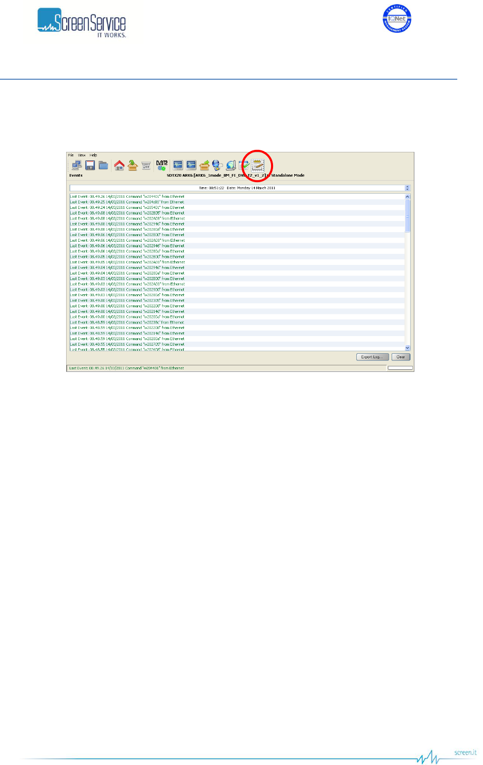
ISO 9001:2000 Cert. N°4500/1
Version 1.1 SDT_ARK6_User_Manual_ENG_vATSC Page 116 of 206
5.14 Events
Click on Events button, highlighted in the next figure, to access the events windows.
Figure 42. Events window
Open the Events window to slide the events list.
Events are reported with the following information:
Time: event detection time.
Date: event detection date.
Type: type of event:
o Alarm;
o Command;
o Event;
o System Init.
Description: event description:
o if the event type is Alarm: which alarm generated the event followed by “ON” or
“OFF”;
o if the event type is Command: the low level code and command source;
o if the event type is Event: event description;
o if the event type is System Init: system initialization, followed by the alarm in case of
error.

ISO 9001:2000 Cert. N°4500/1
Version 1.1 SDT_ARK6_User_Manual_ENG_vATSC Page 117 of 206
Each event type is characterized by a different colour, the following list explain the mean of each colour:
Red: alarm (refer to alarms list in Alarms paragraph and to Alarms list table);
Green: command (See ARK6_SW_Reference manual_v1_0.doc for further information);
Blue: system Init (refer to System Initialization Event paragraph);
Black:
o Event (refer to Events list table);
o TASK_ERR (refer to Task Error Event paragraph);
o SYS_ERR (refer to System Error Event paragraph).
Use the following buttons, sited on the right side of the window, to manage the Events list:
Clear: resets the events list.
Get History: gets all the stored events from the last board reset (max 512 events).
Table 23. Events descriptions list
Description-Event
Event Description
RF OFF enabled from OPTO
RF output switched off through OPTO 0.
RF OFF dis. from OPTO
RF output switched on through OPTO 0.
Stand-by ON from OPTO
Stand-by mode enabled through OPTO 3.
Stand-by ON from LCD
Stand-by mode enabled through LCD button or OPTO 3.
Stand-by ON CPU Fan Err
Stand-by mode enabled because of a CPU Fan error.
Stand-by OFF
Stand-by mode disabled through LCD button.
Power = xx.x dBm (Local)
New output power setting.
xx.x: output power expressed in dBm.
Update file *.xxxx
New file loading.
xxxx: file extension.
P5K open: xx.xx.xx.xx
Connection to port 5000 open.
xx.xx.xx.xx: host IP address.
P5K closed
Connection to port 5000 closed.
File system busy
File system already in use while trying to employ it (e.g. change mode
during a file loading).
Mode = (mode)
Manual change mode.
mode:
"OFF",
"ISDBT",
"ITU",
"DVB-T",
"ATSC",
"DVB-T2",
"ECHO",
"Rep. Analog",
"Rep. Digital".
UTC Time set from GPS
Time and date set by GPS. As soon as the GPS lock is regained,
once lost, and if the current time and date are different from the GPS
ones, the UTC time is set by GPS.

ISO 9001:2000 Cert. N°4500/1
Version 1.1 SDT_ARK6_User_Manual_ENG_vATSC Page 118 of 206
Description-Event
Event Description
PS Restart N
This event is reported when one of the following alarms is raised:
PS1/2 50V voltage out range
PS1/2 50V current out of range
The fourth time one of the preceding alarms is raised the amplifier is
restarted (from 1 up to 4 times).
N: number of amplifier restarting.
Only in SDTX 201 and 501 versions.
PS OFF
After the fourth time the amplifier has been restarted, if an alarm
condition causing a PS Restart event occurs, PS OFF event is
reported and the amplifier is turned off
When this event is reported amplifier can be turned on only by OPTO
2 or by the Restart button in the Output window (only in SDTX 201
and 501 versions).
Restart Amp. from OPTO
This event is reported when the retry command is given by the Retry
Alarm OPTO (OPTO 2).
PS ON
This event is reported at every amplifier restarting
Events List cleared
This event is reported when the events list is cleared.
Updating string fw...
This event is reported when the update of the FPGA firmware starts.
String values:
"ISDBT",
"ITU",
"DVB-T",
"ATSC",
"DVB-T2",
"ECHO",
"Rep. Analog",
"Rep. Digital".
FPGA firmware err xx
This event is reported when an error occurs during the update of the
FPGA firmware.
xx: error code:
0x10, 0x20, 0x01, 0x02, 0x03: programming error;
0x11: firmware not found in FS (for the current mode);
0x22: FPGA file opening error;
0x33: FPGA file reading error;
0x44: erasing FLASH memory block error.
FPGA firmware OK
New FPGA firmware successfully loaded.
Saving config…
Saving configuration task started (after the command “s” given by
RS232 or GbE commands).
Save config Finished
Saving configuration task correctly ended.
Save config error: xx
An error occurs during saving configuration.
xx: error code:
0x80: File system busy;
0x01: New *.sav file opening error;
0x02: uC header writing error;
0x03: uC data writing error;
0x04: FPGA header writing error;
0x05: FPGA data writing error;
0x07: File date writing error;
0x08: Old *.sav file deleting error
0x09: New file naming error (deleting of “*”);
0x0A: File date writing error it can’t be found into the FS
0x10: file already opened.
Pwr adjusted to xx.x dBm
New output power setting due to a set value exceeding the mode
specific power range.
xx.x: output power expressed in dBm.

ISO 9001:2000 Cert. N°4500/1
Version 1.1 SDT_ARK6_User_Manual_ENG_vATSC Page 119 of 206
Description-Event
Event Description
In. AUTO switch to string
When Input Select Mode is set on Autoswitch and the selected input
is not locked the device switch to the next available locked input (refer
to Task Error Event paragraph) and this event is generated.
string:
ASI1
ASI2
ASI3
ASI4
Tuner
RxCh1
RxCh2
Forced = mode
If the device is in Mode A and the selected working mode is disabled
by default (as established in the MODE_DIS field of the *.def file), the
next available working mode is forced.
mode:
"ISDBT",
"ITU",
"DVB-T",
"ATSC",
"DVB-T2",
"ECHO",
"Rep. Analog",
"Rep. Digital".
Forced Ch In A= string
Channel input.
Forced ChOut A= string
Channel output.
Forced reset for IIC err
An IIC error forced the board reset.
=>string err status
It notifies witch file generated the Bad file in File System alarm.
string: file extension
status: ON or OFF
ERR on delete file ‘string‘
After a FS file update the old file is renamed and then deleted. This
event is reported when the deletion of the old file during the system
initialization does not succeed.
string: file extension.
Delete file ‘string‘
FS file deleted.
string: file extension.
Init FS date
This event is reported once time and date table of the File System is
initialized for the first time.
Error init FS date xx
An error occurs during FS initialization.
xx: error code:
0x01: EEPROM data reading error;
0x02: EEPROM data writing error;
0x03: CRC error in time and date table.
Error on delete *.string
FS file deleting error.
string: file extension.
S1/S2 changed, P1 loading
Automatic update of P1 symbol. This event is reported at every
system initialization and, in T2-MI mode, when S1 and S2 fields of
incoming T2-MI pkts change.
Saving drlin …
Saving linear coefficients task started (after the command “p2” given
by RS232 or GbE commands).
Saving drlin Finished
Saving linear coefficients task correctly ended.

ISO 9001:2000 Cert. N°4500/1
Version 1.1 SDT_ARK6_User_Manual_ENG_vATSC Page 120 of 206
Description-Event
Event Description
Save drlin err: xx
An error occurs during saving linear precorrection coefficients.
xx: error code:
0x80: File system busy;
0x01: New *.drlin file opening error;
0x02: number of coefficients information writing error;
0x03: linear coefficients writing error;
0x07: File date writing error;
0x08: Old *.drlin file deleting error
0x09: New file naming error (deleting of “*”);
0x10: file already opened;
0x0A: File date writing error it can’t be found into the FS.
New T2MI PID N
New T2-MI PID found by the Automatic T2-MI PID Mode mechanism.
IIC Error
IIC bus error
DVB-T2 params err xx
An error occurs during T2 parameters loading.
xx: error code:
0x01: P1 symbol loading error;
0x02: P1 symbol loading error due to a not valid T2-MI input.
Re-start mode
When DVB-T2 params err 01 occurs during T2 parameters loading,
the FPGA firmware is reloaded and this event is generated.
DVB-T2 preset err xx
An error occurs during T2 preset configuration loading.
xx: error code:
0x80: File system busy;
0x01: *.t2cfg file opening error;
0x02: *.t2cfg file header reading error;
0x03: the selected configuration is corrupted;
0x04: preset configuration data too big;
0x05: memory allocation error;
0x06: *.t2cfg file header reading error;
0x09: *.t2cfg file not found;
0x10: the selected configuration is not present.
RFL Power Warning
RFL power goes over the alarm threshold for the first time and the
“Number of attempts” is different from zero.
RFL Power OK
RFL power goes under the alarm threshold.
RFL Power Alarm
RFL power goes over the alarm threshold for N times, where N is the
number of attempts specified in the Output page of the Java GUI.
RFL RF ON ”N”
When RFL power goes over the alarm threshold the system switch off
and on the output RF signal for a maximum number of times. N is the
current number of attempt.
T2-MI Autodetect PID OK
The Automatic T2-MI PID detection has been put across
T2MI PID PAT Err
During Automatic T2-MI PID operations, PAT has not been found in
the input Transport Stream.
T2-MI PID Not Valid
During Automatic T2-MI PID operations, no PIDs with stream type
x06 has been found in the PMT.
T2MI PID PMT Err
During Automatic T2-MI PID operations, more than one PID with
stream type x06 has been found in the PMT.
T2-MI PID Not Found
During Automatic T2-MI PID operations, the detected T2-MI PID has
not been found in the input Transport Stream
Freq Ref Forced: GPS
If the Network mode is SFN but the clock reference is set to Internal,
the frequency reference is automatically forced to GPS and this event
is generated.
Freq Ref set to string
Event generated at every new Frequency Reference selection.
string: the clock reference
External
Internal
GPS

ISO 9001:2000 Cert. N°4500/1
Version 1.1 SDT_ARK6_User_Manual_ENG_vATSC Page 121 of 206
Description-Event
Event Description
Holdover OFF
Condition 1: the clock reference is changed and the OCXO is not
locked yet.
Condition 2: the input clock reference is not present.
Holdover SFN Ready
The OCXO is locked to the selected frequency reference and the
system is waiting for the OCXO stabilization.
Holdover Ready
Condition 1: the OCXO is stable and the Holdover function is now
available.
Condition 2: the system quit the Holdover mode because the OCXO
regain the lock to the selected clock reference.
Holdover ON
If the OCXO is no more locked to the selected frequency reference
and the Holdover function is enabled and available, the equipment
enters in holdover mode.
Holdover TMO Expired
Condition: the Holdover state is “ON” (the function is enabled) and the
Holdover timeout period elapses prior to regain the lock of the
selected clock reference source.
Fan N Speed string
It notifies which fan caused the Fans Speed Low alarm.
string:
Low;
OK
Updating GPS fw…
This event is reported when the update of the GPS firmware starts.
GPS firmware err xx
This event is reported when an error occurs during the update of the
GPS firmware.
xx: error code:
0x80: File system busy;
0x01: firmware not found in FS (for the current mode);
0x02: GPS file opening error;
0x03: GPS file reading error;
0x06:GPS fw transferring into buffer error.
GPS firmware OK
New GPS firmware successfully loaded.
Updating GPS fw (NILL)…
When an error occurs during the update of the GPS firmware, the
system reloads the Nill firmware prior to attempt another update.
The following table lists the descriptions of all the alarm type events (refer to Alarms paragraph for
further information about alarms).
Table 24. Alarms descriptions list
Alarm
Description-Alarm
Temperature Absolute High
Temp. High
Temperature Alarm (-3dB)
Temp. High -3dB
Temperature Warning
Temp. High Warning
Fans Speed Low
Fans Speed Low
Alim Dialog Err
Alim Dialog Err
FE Dialog Err
FE Dialog Err
Meas Dialog Err
Meas Dialog Err
GPS Dialog Err
GPS Dialog Err
GPS Not Locked
GPS Not Locked
120MHz Not Locked
120MHz Not Locked

ISO 9001:2000 Cert. N°4500/1
Version 1.1 SDT_ARK6_User_Manual_ENG_vATSC Page 122 of 206
Alarm
Description-Alarm
960MHz Not Locked
960MHz Not Locked
Input PLL Not Locked
Input PLL Not Locked
Output PLL Not Locked
Out PLL Not Locked
10MHz Not Locked
10MHz Not Locked
1PPS Not Locked
1PPS Not Locked
FPGA Boot Error
FPGA Boot Err
Forward Power High
FWD Power High
Forward Power Low Warning
FWD Pwr Low Warning
Forward Power Low Alarm
FWD Pwr Low
Reflex Power High
Reflex Power High
File System Error
File System Err
Bad File In File System
File Err
PS Voltage Out Of Range
PS1 V Out Of Range
PS Current Out Of Range
PS1 I Out Of Range
CPU Fan Error
CPU Fan Error
Test Mode
Test Mode
FE S2 Not Locked
FE S2 not locked
FE S2 S/N Low
FE S2 SNR Low
FE S2 BER High
FE S2 BER high
FE S2 Global Alarm
[DVB-T2] No Input
No Input
[DVB-T2] Input Overflow
Input overflow
[DVB-T2] FE Not Locked
FE Not Locked
[DVB-T2] FE Squelch
FE Squelch
[DVB-T2] FE Pre LDPC BER High
FE Pre LDPC BER
[DVB-T2] FE SNR Low
FE SNR Low
[DVB-T2] FE MER Low
FE MER Low
[DVB-T2] FE Signal Quality Low
FE S.Quality Low
[DVB-T2] MEAS Not Locked
Meas Not Locked
[DVB-T2] MEAS Pre LDPC BER High
Meas Pre LDPC BER
[DVB-T2] MEAS SNR Low
Meas SNR Low

ISO 9001:2000 Cert. N°4500/1
Version 1.1 SDT_ARK6_User_Manual_ENG_vATSC Page 123 of 206
Alarm
Description-Alarm
[DVB-T2] MEAS MER Low
Meas MER Low
[DVB-T2] MEAS Signal Quality Low
Meas S.Quality Low
[DVB-T2] T2-MI Err
T2-MI Err
[DVB-T2] T2-MIP Err
T2-MIP Err
[DVB-T2] Holdover
Holdover
[DVB-T2] PPS Phase
PPS Phase
[DVB-T2] Configuration Not Loaded
Cfg. Not Loaded
[DVB-T2] FE LDPC Mean Err
FE LDPC Mean Err
[DVB-T2] MEAS LDPC Mean Err
MEAS LDPC Mean Err
[DVB-T2] SFN Alarm
SFN Alarm code
code:
Bit[0]: the Holdover function is enabled and the OCXO
is not locked yet
Bit[1]: the Timestamp is not present
Bit[2]: wrong Timestamp CRC
Bit[3]: wrong Timestamp
Bit[4]: SFN Resynch
[DVB-T] Input Not Present
Input not present
[DVB-T] Input Not valid Alarm
Input not valid
[DVB-T] MIP Delay High
MIP delay high
[DVB-T] No Input
Input not detected
[DVB-T] Input Overflow
Input overflow
[DVB-T] MIP Err
MIP error
[DVB-T] PPS Phase
PPS phase wrong
[DVB-T] SFN Alarm
SFN Alarm
[DVB-T] FE Not Locked
FE Not Locked
[DVB-T] FE Squelch
FE Squelch
[DVB-T] FE Pre Viterbi BER High
FE Pre Vit BER
[DVB-T] FE SNR Low
FE SNR Low
[DVB-T] FE MER Low
FE MER Low
[DVB-T] FE Signal Quality Low
FE S.Quality Low
[DVB-T] MEAS Not Locked
Meas Not Locked
[DVB-T] MEAS Pre Viterbi BER High
Meas Pre Vit BER

ISO 9001:2000 Cert. N°4500/1
Version 1.1 SDT_ARK6_User_Manual_ENG_vATSC Page 124 of 206
Alarm
Description-Alarm
[DVB-T] MEAS SNR Low
Meas SNR Low
[DVB-T] MEAS MER Low
Meas MER Low
[DVB-T] MEAS Signal Quality Low
Meas S.Quality Low
[DVB-T] Holdover
Holdover
[ITU] No Video Input
Input not detect
[ITU] Input wrong format
Wrong standard
[ITU] Holdover
Holdover
[ISDB-T] Input Error
Input not valid
[ISDB-T] IIP Modulation Error
IIP error
[ISDB-T] 1PPS Phase
PPS phase wrong
[ISDB-T] System delay
System delay alarm
[ISDB-T] IIP SFN error
IIP SFN err
[ISDB-T] Network delay
Network Delay
[ISDB-T] Rate error Layer A
Layer A Err Rate
[ISDB-T] Rate error Layer B
Layer B Err Rate
[ISDB-T] Rate error Layer C
Layer C Err Rate
[ISDB-T] Table Overflow Layer A
Lay A Table ovfl
[ISDB-T] Table Overflow Layer B
Lay B Table ovfl
[ISDB-T] Table Overflow Layer C
Lay C Table ovfl
[ISDB-T] MEAS not locked
Meas Not Locked
[ISDB-T] MEAS CN Low
Meas C/N Low
[ISDB-T] MEAS MER Layer A
Meas MER A Low
[ISDB-T] MEAS MER Layer B
Meas MER B Low
[ISDB-T] MEAS MER Layer C
Meas MER C Low
[ISDB-T] MEAS Pre-Viterbi BER High Layer A
Meas Pre Vit A BER
[ISDB-T] MEAS Pre-Viterbi BER High Layer B
Meas Pre Vit B BER
[ISDB-T] MEAS Pre-Viterbi BER High Layer C
Meas Pre Vit C BER
[ISDB-T] FE Not Locked
FE Not Locked
[ISDB-T] FE Squelch
FE Squelch

ISO 9001:2000 Cert. N°4500/1
Version 1.1 SDT_ARK6_User_Manual_ENG_vATSC Page 125 of 206
Alarm
Description-Alarm
[ISDB-T] FE CN Low
FE C/N Low
[ISDB-T] FE MER Layer A
FE MER A Low
[ISDB-T] FE MER Layer B
FE MER B Low
[ISDB-T] FE MER Layer C
FE MER C Low
[ISDB-T] FE Pre-Viterbi BER High Layer A
FE Pre Vit A BER
[ISDB-T] FE Pre-Viterbi BER High Layer B
FE Pre Vit B BER
[ISDB-T] FE Pre-Viterbi BER High Layer C
FE Pre Vit C BER
[ISDB-T] FE Emergency Flag
FE emergency flag
[ATSC] No Input
Input not valid
[ATSC] Input Overflow
Input overflow
[ATSC] MH Err
MH Error
[ATSC] MEAS Demodulator Not Locked
Meas Not Locked
[ATSC] MEAS SNR Low
Meas SNR Low
[ATSC] FE Demodulator Not Locked
FE Not Locked
[ATSC] FE SNR Low
FE SNR Low
[ATSC] No TVCT
TVCT Not Present

ISO 9001:2000 Cert. N°4500/1
Version 1.1 SDT_ARK6_User_Manual_ENG_vATSC Page 126 of 206
5.14.1 Date and Time Setting
The upper part of the event window shows the actual time and date and allows the manual setting of
those parameters.
Figure 43. Time and date setting
Click to each part of the date and time to change the parameter and then increase or decrease its value
with the up/down arrows.
Note: When the onboard GPS receiver is locked and GPS frequency reference is enabled, the date and
time information are received by GPS satellite and updated every thirty seconds.
The board incorporates a rechargeable battery to maintain the time when there isn’t a power supply.
The battery supplies the clock for two or three days, after that the time shall be reset either by char
interface, or LCD display, or Java interface or selecting the GPS as frequency reference.
5.14.2 Task Error Event
The watchdog performs a periodic (every 20 seconds) polling of tasks and triggers a system reset if one
or more tasks do not answer, restarting the Code loader (See Codeloader_Operations_Note_v1.1.doc for
further information) and generating a TSK ERR event as follows:
The blue underlined 32-bits word is the enabling status of the alarms mask. The red underlined 32-bits
word indicates the status of tasks (1 if the task has been successfully performed, otherwise 0) as
specified in the following table:
Table 25. Task error event specific data
TASK
Description
Bit
WD_FAN_TASK
This task controls fans speed on the basis of the board
temperature.
0
WD_UPCV_TASK
This task controls the Up-converter status.
1
WD_GPS_TASK
This task controls the GPS status.
2
WD_STATUS_TASK
This task gathers quite all the board information in order to
perform the following operations:
It updates all variables of the system;
It manages alarms;
It manages the RF status (e.g. on, off…);
It manages the mode switch;
It manages the ARP resolution in DVB mode.
3
TSK ERR 00000028, 0000003c

ISO 9001:2000 Cert. N°4500/1
Version 1.1 SDT_ARK6_User_Manual_ENG_vATSC Page 127 of 206
TASK
Description
Bit
WD_TCP_IP_TASK
This task implements the TCP-IP protocol stack.
4
WD_TIMER_TICK_TASK
This task generates the clock for the TCP-IP task.
5
WD_STV0362_TASK
This task gathers information from both the HP and LP tuners
and configures them.
6
WD_ARK6AL_TASK
This task gathers information from:
Get ADC value
Get Amplifier Voltage and current measure
Calculate FWD power level
Output AGC
Calculate Reflex power
Get temperature
Get opto & relay status
Disable alim status
7
The default tasks mask at the board startup is set to 0x0000007D (please note that the up-converter task
is initially skipped). Once the presence of the up-converter is assured, the up-converter task bit is
automatically enabled and the mask is set to 0x0000007F. Tasks execution is stopped during de-
fragmentation operations and FPGA boots.
5.14.3 System Error Event
For critical and fatal errors, the system calls the system error function and the SYS_ERR event is
reported.
The error codes are described below:
0x00: Out of memory. Memory pool size is too small.
0x01: Invalid memory block release. Buffer data has been written out of boundaries of the
allocated memory block.
0x02: Link pointer corrupted. Buffer data has been written out of boundaries of the allocated
memory block.
0x03: No free UDP Sockets. The system has run out of UDP Sockets.
0x04: No free TCP Sockets. The system has run out of TCP Sockets.
0x05: TCP socket is in an undefined state. System memory has been accidentally overwritten.

ISO 9001:2000 Cert. N°4500/1
Version 1.1 SDT_ARK6_User_Manual_ENG_vATSC Page 128 of 206
5.14.4 System Initialization Event
At every system initialization the event System Init is generated.
This event is followed by 25 bytes specifying type and specific code of errors occurred during system
initialization.
Each byte refers to an error as described in the following table:
Table 26. Init system event specific data
Description
Errors code
Byte
FS_ERR
File System error.
0x00: File System ok.
0x01: FS partition error (invalid FS).
1°
INFO_ERR
*.cfg file error.
0x00: File ok.
0x01: File not found or File open error.
0x02…0x03: Invalid file (syntax errors).
2°
DEF_ERR
*.def file error.
0x00: File ok.
0x01: File open error.
0x02: File not found.
3°
LCD_ERR
LCD error.
0x00: LCD ok.
0x01: LCD not found.
4°
PLL_960M_ERR
960 MHz PLL error.
0x00: PLL locked.
0x01: PLL not locked
5°
BOOT_ERR
FPGA boot error.
0x00: FPGA boot ok.
0x01: FPGA NILL boot error
0x02: FPGA file version error
0x03: FPGA code error.
6°
LOAD_CFG_ERR
*.sav file error.
0x00: File ok.
0x01: File open error.
0x02…0x05: Invalid file (syntax errors).
7°
SNMP_ERR
SNMP file error.
0x00: SNMP file ok.
0x01: SNMP file not found.
0x02: File open error.
0x03: UDP socket initialization error.
0x04: Port 161 open error.
8°

ISO 9001:2000 Cert. N°4500/1
Version 1.1 SDT_ARK6_User_Manual_ENG_vATSC Page 129 of 206
Description
Errors code
Byte
CALIB_ERR
*.pwr file error.
0x00: File ok.
0x01: Current AGC mode file not found.
0x02: Current AGC mode file open error.
0x03…0x12: Invalid current AGC mode file (syntax error).
0x20: Other AGC mode file not found
0x21: Other AGC mode file open error.
0x22…0x26: Invalid other AGC mode file (syntax error).
Please note that the AGC mode may be analog or digital.
Actual AGC mode is displayed in Java output window.
9°
PREC_ERR
0x00: File ok.
10°
LINEAR_ERR
0x00: File ok.
0x01: File not found.
0x02: File open error.
0x03…0x06: Invalid file (syntax errors).
11°
DOWNCV_ERR
Downconverter PLL not
locked error.
0x00: PLL locked.
0x01: PLL not locked
0x10: PLL disabled.
12°
UPCV_ERR
Upconverter error.
0x00: Upconverter ready.
13°
CH_FILT_ERR
*.chf7 or *.chf8 file error.
0x00: File ok.
0x01: File not found.
0x02: File open error.
0x03…0x06: Invalid file (syntax errors).
Please note that checked file is the one which refers to the
current signal bandwidth: *.chf7 refers to VHF bandwidth, *.chf8
refers to UHF bandwidth.
14°

ISO 9001:2000 Cert. N°4500/1
Version 1.1 SDT_ARK6_User_Manual_ENG_vATSC Page 130 of 206
Description
Errors code
Byte
CH_DEF_ERR
*.cdef file error.
0x00: File ok.
0x01: File not found.
0x02: File open error.
0x03: syntax error or lack of input number of channels.
0x13: syntax error or lack of output number of channels.
0x04: input channels memory allocation error.
0x14: output channels memory allocation error.
0x05: when the automatic indexing of channels listed in
*.cdef file is disabled, it notifies syntax errors or lack of input
channels definition lines.
0x15: when the automatic indexing of channels listed in
*.cdef file is disabled, it notifies syntax errors or lack of
output channels definition lines.
0x06: when the automatic indexing of channels listed in
*.cdef file is enabled, it notifies syntax errors or lack of input
channels definition lines.
0x16: when the automatic indexing of channels listed in
*.cdef file is enabled, it notifies syntax errors or lack of
output channels definition lines.
15°
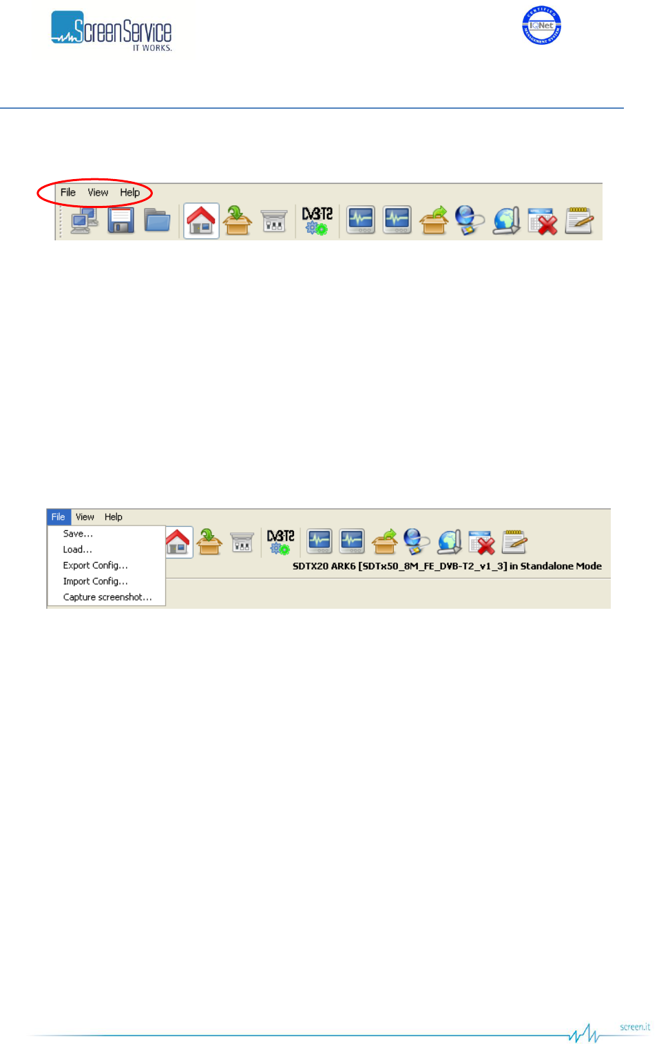
ISO 9001:2000 Cert. N°4500/1
Version 1.1 SDT_ARK6_User_Manual_ENG_vATSC Page 131 of 206
5.15 System menu
Figure 44. Menu bar
The menu bar allows the access to three menus:
File: allows to import/export the configuration file, to load and save the board configuration
and to download the screenshots of the Java GUI;
View: allows to navigate windows and to configure java update time and events alert massages;
Help: allows to access information such as board name, board IP address, serial numbers of HW
components, File System content, an abstract of the User Manual and system characteristics.
5.15.1 File Menu
Figure 45. File menu
The File menu is structured as follows:
Save: saves the current device configuration.
Load: loads the last saved configuration.
Export Config: exports last saved configuration of the device (the *.sav file).
Import Config: imports a new configuration file (the *.sav file).
Capture screenshots: downloads a screenshot for each one of the selected windows.
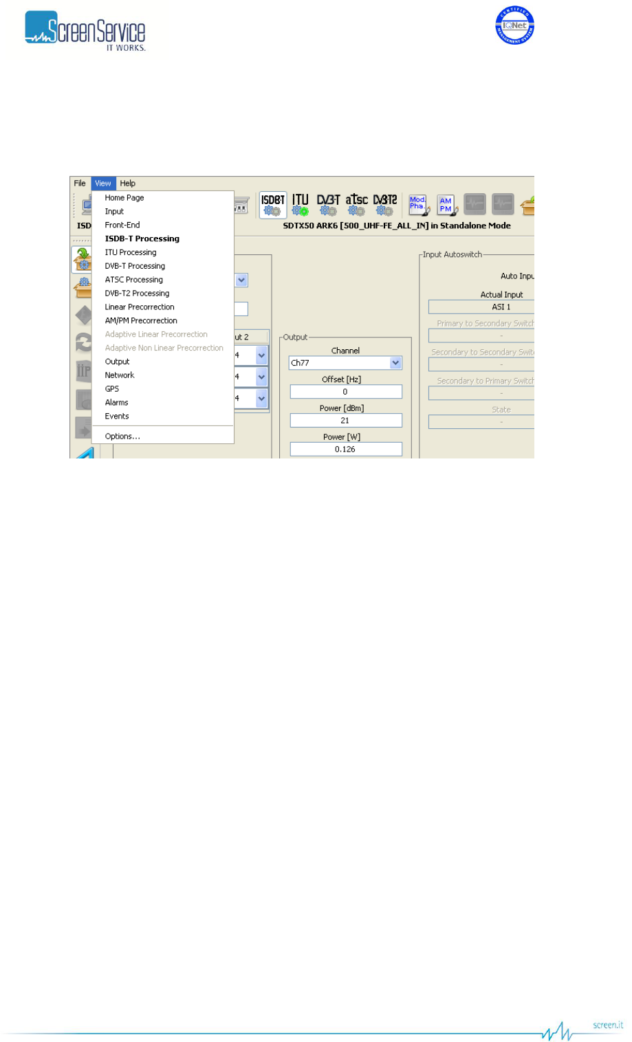
ISO 9001:2000 Cert. N°4500/1
Version 1.1 SDT_ARK6_User_Manual_ENG_vATSC Page 132 of 206
5.15.2 View Menu
Figure 46. View menu
The View menu allows accessing the following windows:
Home Page
Input
Front-End
ISDB-T Processing
ITU Processing
DVB-T Processing
ATSC Processing
DVB-T2 Processing
Linear Precorrection
AM/PM Precorrection
Adaptive Linear Precorrection
Adaptive Non Linear Precorrection
Output
Network.
GPS.
Alarms
Events: Events window.
Options...: Options window.
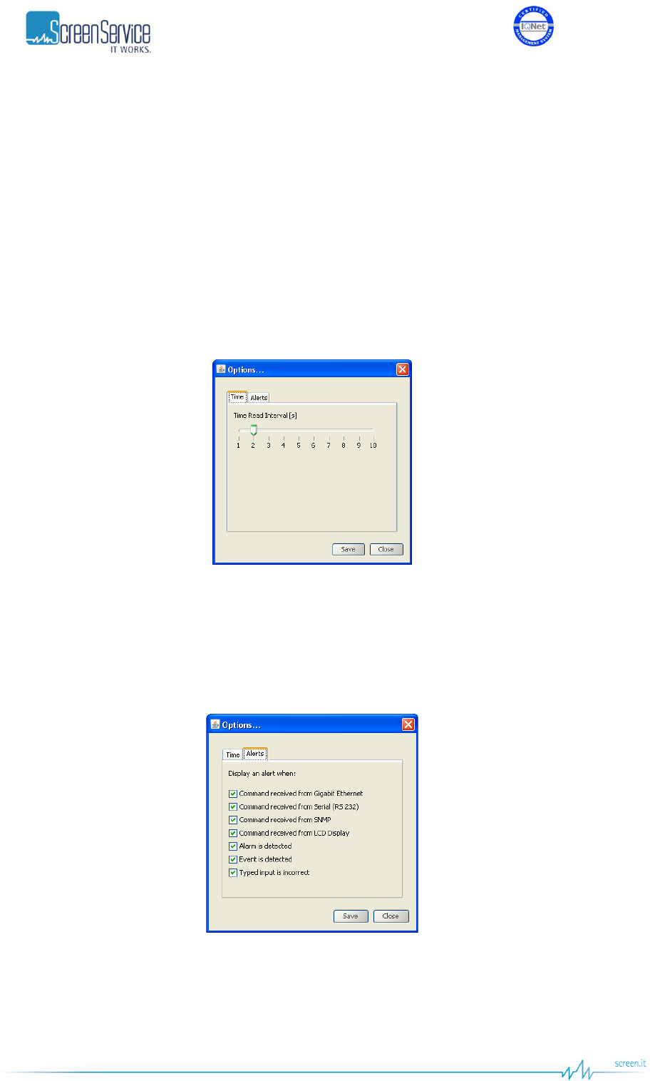
ISO 9001:2000 Cert. N°4500/1
Version 1.1 SDT_ARK6_User_Manual_ENG_vATSC Page 133 of 206
5.15.2.1 Options window
The Options window has two tabs:
Time: Time Read Interval [s];
Alerts: the selection of events to display.
Click on the Save button to save Java options; a new *.properties file will be created.
The device is not loaded with a factory default *.properties file, but it is created and then stored in
System File once properties are saved for the first time.
5.15.2.1.1 Time
Figure 47. Time window
This control allows changing the device-to-management PC java update time. The default value is 2
seconds. Click on Close button to quit this window.
5.15.2.1.2 Alerts
Figure 48. Alerts window
Alerts tab allows selecting which types of events will be notified through Alert boxes. Alerts appear on
the right side of the monitor.
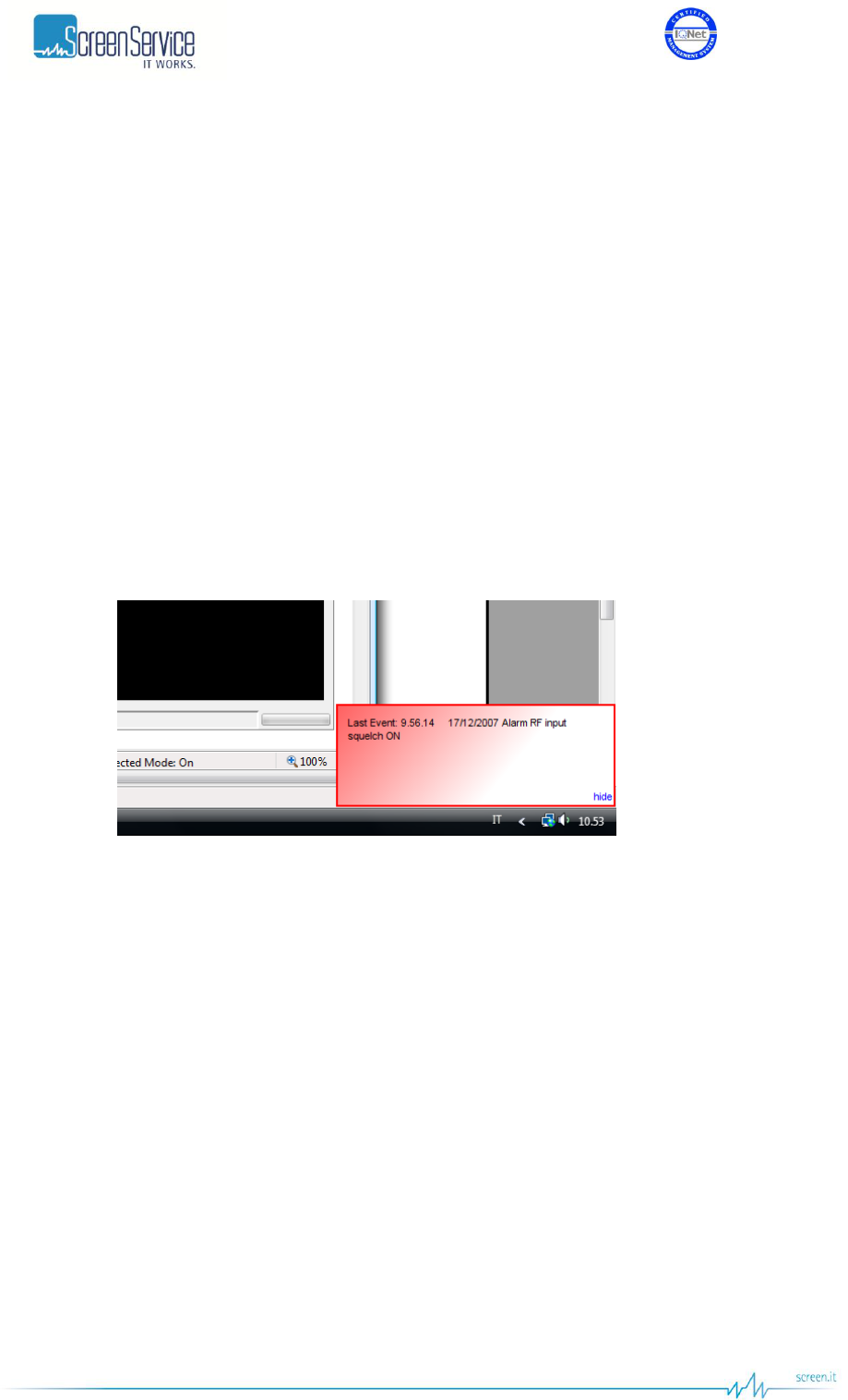
ISO 9001:2000 Cert. N°4500/1
Version 1.1 SDT_ARK6_User_Manual_ENG_vATSC Page 134 of 206
The selection is performed among the following types of event:
Commands (blue boxes):
o Gigabit Ethernet commands;
o RS232 commands;
o SNMP commands;
o LCD Display commands.
Alarms (red boxes);
Events (green messages):
o Board events.
Typing error (yellow messages):
o Typed setting is incorrect.
Click on hide button to close alerts popup windows.
Figure 49. Alert message
Alerts can be disabled through the hide button located on the right side of the box.
The hide button, once clicked, disables all boxes belonging to the same class.
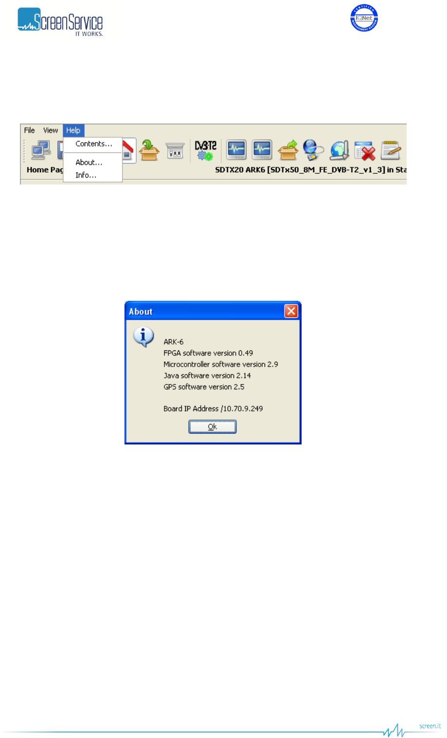
ISO 9001:2000 Cert. N°4500/1
Version 1.1 SDT_ARK6_User_Manual_ENG_vATSC Page 135 of 206
5.15.3 Help Menu
Figure 50. Help menu
The Help menu allows to select one of the following options:
Contents: Help with an abstract of the User Manual.
About: shows the board name and the management IP address. It also provides uC, FPGA, Java
and GPS software versions. Click on OK button to close the window.
Figure 51. About window
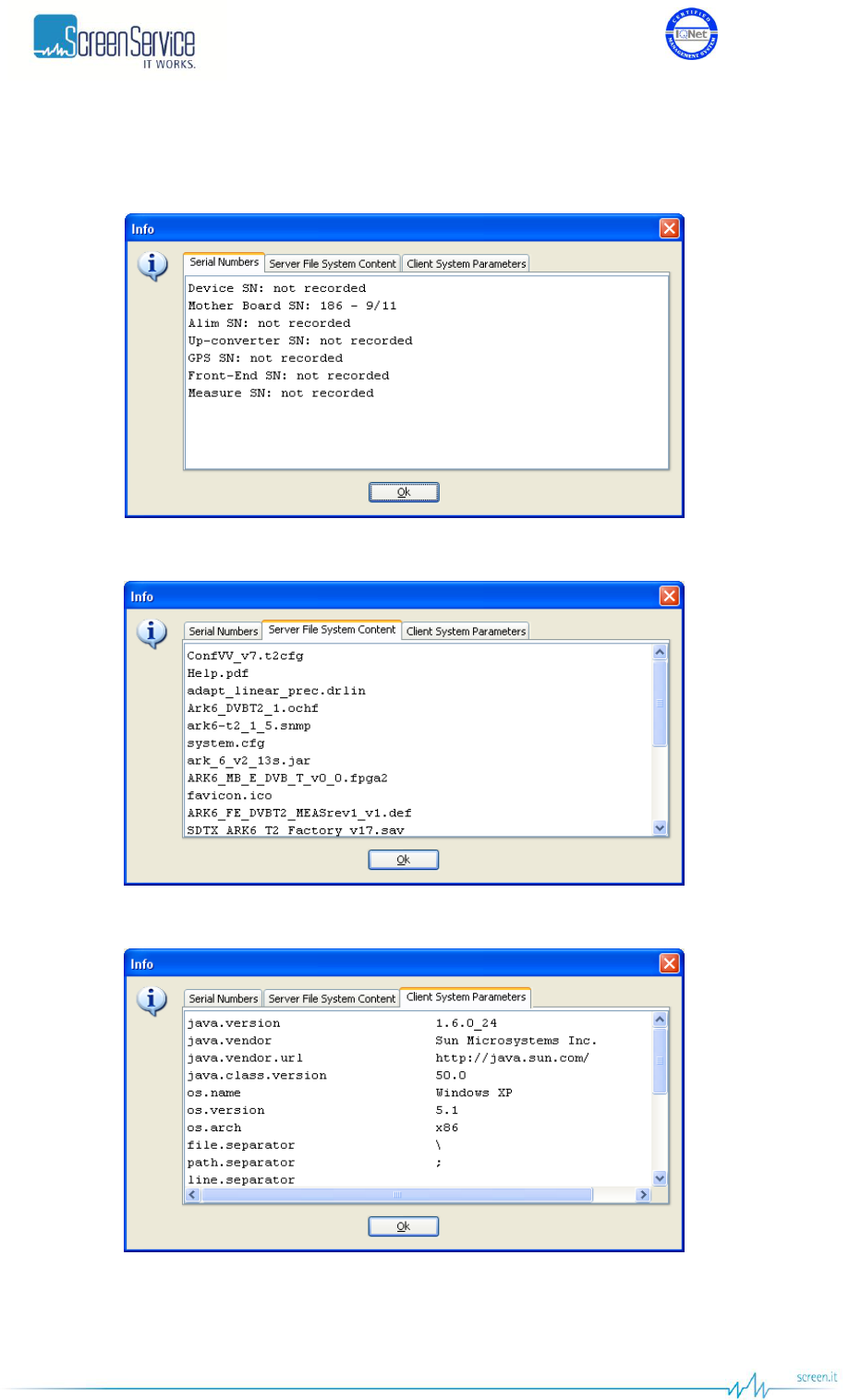
ISO 9001:2000 Cert. N°4500/1
Version 1.1 SDT_ARK6_User_Manual_ENG_vATSC Page 136 of 206
Info: shows serial numbers of HW components, File System content and the managed system
characteristics. Click on OK button to close Info window.
Figure 52. Info window: Serial Numbers
Figure 53. Info window: Server File System Content
Figure 54. Info window: Client System Parameters
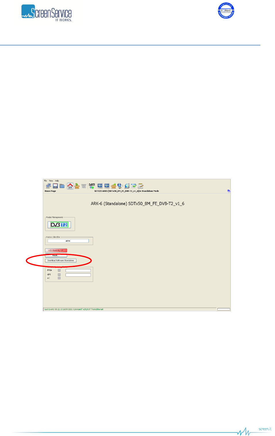
ISO 9001:2000 Cert. N°4500/1
Version 1.1 SDT_ARK6_User_Manual_ENG_vATSC Page 137 of 206
5.16 Download Software Standalone
The Download Software Standalone button allows the downloading of standalone Java application
(executable *.jar file) based on java applet.
If your browser is Internet Explorer, it may block the site from downloading files to your computer. If you
want to enable the file downloading, follow the instructions listed below:
Open Internet Explorer;
Click on the Tools button and then click on Internet Options;
Click on the Security tab and then click on Custom level button;
To turn off the Information bar for file downloads, scroll to the Downloads section of the list, and
then, under Automatic prompting for file downloads, click on Enable;
Click on OK, click Yes in order to confirm that you want to make the change, and then click OK
again.
Figure 55. Download Software Standalone
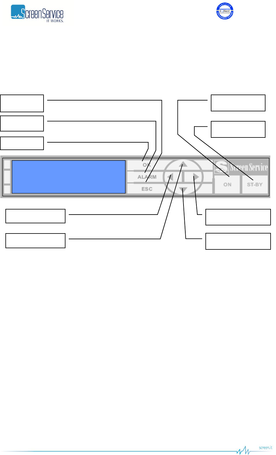
ISO 9001:2000 Cert. N°4500/1
Version 1.1 SDT_ARK6_User_Manual_ENG_vATSC Page 138 of 206
6 Local User Interface
The following paragraphs describe the local user interface for ARK6 T2. This user interface is composed
of LCD Display, seven buttons and two status LEDs. Here below is depicted the ARK6 Front Panel.
STAND-BY: push this button (lie in wait for two seconds) to put the equipment on STAND-BY
mode. The orange led lights up and the written STAND-BY MODE appears on the display. The
remote Stand-by mode is enforceable only if on JAVA interface this feature is enabled.
ON: push this button (lie in wait for two seconds) to turn on the equipment. The green led lights
up and the MAIN MENU is displayed.
OK: push this button to select or to confirm the sub-menu or the value respectively. Touching
the screen with a finger the green led lights up.
ESC: push this button to quit a submenu and to return to the previous one. Touching the screen
with a finger the green led lights up.
ALARM: when an alarm occurs the RED LED lights up.
UP ARROW: push this button to scroll up menus or to increase a value. Touching the screen
with a finger the green led lights up.
DOWN ARROW: push this button to scroll down menus or to decrease a value. Touching the
screen with a finger the green led lights up.
LEFT ARROW: push this button to move within a string. Touching the screen with a finger the
green led lights up.
RIGHT ARROW: push this button to move within a string. Touching the screen with a finger the
green led lights up.
OK
ALARM
ESCAPE
ON
STANB-BY
LEFT ARROW
UP ARROW
RIGHT ARROW
DOWN ARROW
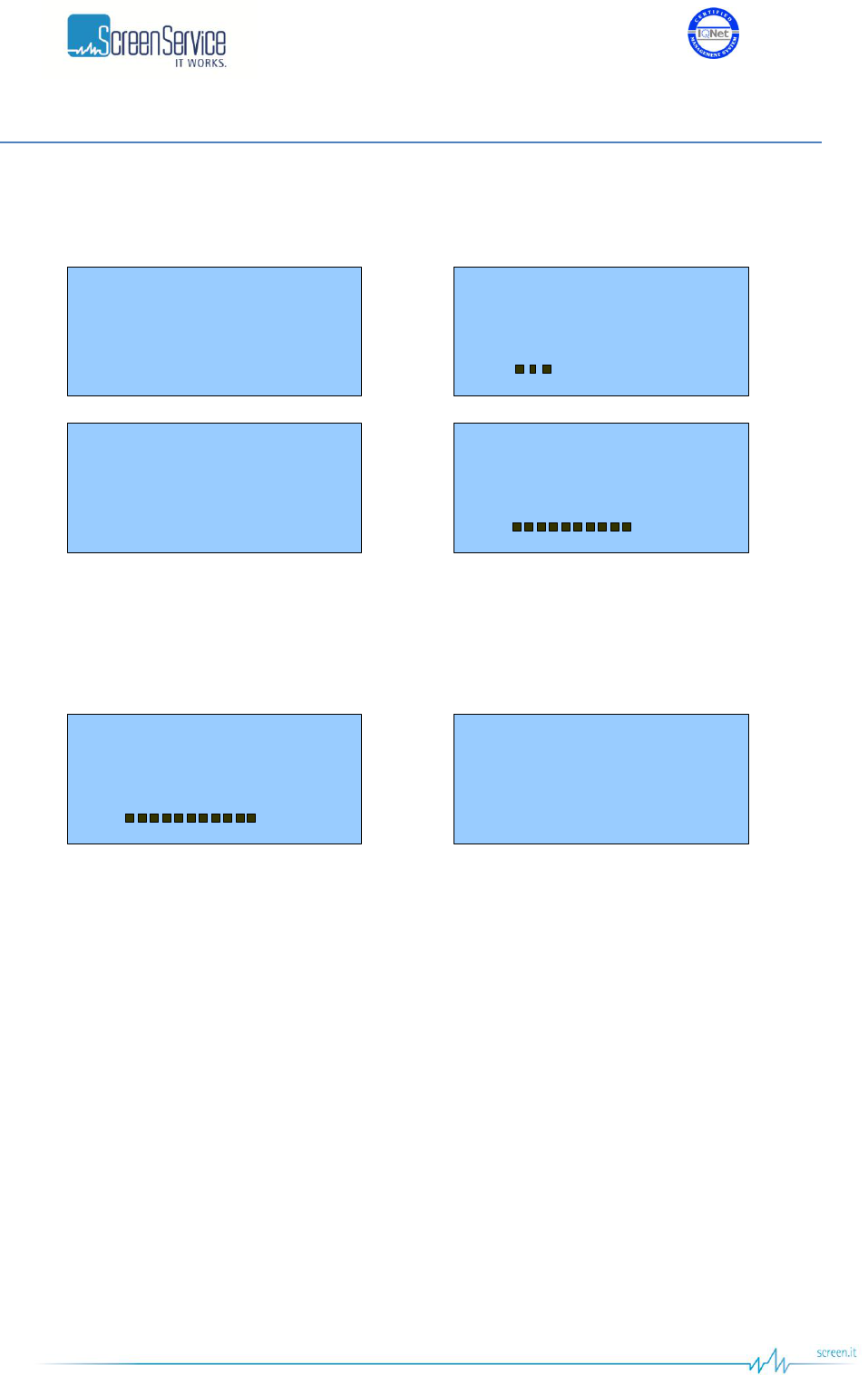
ISO 9001:2000 Cert. N°4500/1
Version 1.1 SDT_ARK6_User_Manual_ENG_vATSC Page 139 of 206
6.1 Boot and Welcome Message
Turning on the equipment, the display shows the progress bar as follow:
Screen Service
ARK - DVB-T2
System Init
Init : [ ] Wait
Screen Service
ARK - DVB-T2
Boot FPGA
Init : [ ] Wait
Screen Service
ARK - DVB-T2
Start system
Init : [ ] Wait
Screen Service
ARK - DVB-T2
Start system
Init : [ ] Ready
When the boot is over, the device is ready.
Screen Service
ARK - DVB-T2
Start system
Init : [ ] Ready
Screen Service
ARK - DVB-T2
IP 10.77.98.44
Ready
Press ESC to enter the main menu, otherwise after one minute waiting the idle status message appears.

ISO 9001:2000 Cert. N°4500/1
Version 1.1 SDT_ARK6_User_Manual_ENG_vATSC Page 140 of 206
6.2 Idle Menu
ARK - DVB-T2
In:ASI1
Out 17.1dBm CH:22
UTC: 14:11 10/03/11
This menu appears after one minute waiting from the last touch. Information contained in the Idle Menu
are described in next table.
Table 27. Local User Interface: Idle Menu
Information
Description
ARK – DVB-T2 (ATSC)
Device description
In
Input signal source
Out
Output power and channel
IP
Management IP address (GBE 1)
UTC
UTC time and date
Press ESC to enter the MAIN MENU.

ISO 9001:2000 Cert. N°4500/1
Version 1.1 SDT_ARK6_User_Manual_ENG_vATSC Page 141 of 206
6.3 Main Menu
Events
Network setup
Time & Date setup
/ OK: SET
/
This menu shows six SUBMENUs. It is possible to view them sliding the menu up and down, with the UP
or DOWN ARROWS, and to select one of them by pushing OK button.
Submenus contained in the Main Menu are described in next table.
Table 28. Local User Interface: submenus descriptions
Submenu
Description
Network setup
Enter this submenu to set:
GbE1 Board IP address
GbE1 Gateway address
GbE1 Netmask
GbE2 IP address
GbE2 Gateway address
GbE2 Netmask
Settings in this submenu do not need to be saved; they will be loaded
at next device restart.
Time & Date setup
Enter this submenu to set:
Time
Date
Settings in this submenu do not need to be saved in order to be
loaded at next device restart.
System Status
Enter this submenu to monitor system status and installer version the
device is loaded with.
Alarms
Alarms, detected and associated to the local interface by the relative
mask, are listed in this submenu.
Reset system
Enter this submenu to reset the device.
Events
Enter this submenu to manage and monitor the events list.

ISO 9001:2000 Cert. N°4500/1
Version 1.1 SDT_ARK6_User_Manual_ENG_vATSC Page 142 of 206
6.4 LCD Alarms
Through the LCD Alarms mask it is possible to select which alarm has to be notified on LCD display. When
an alarm condition occurs the alarm button is lighted and an alarm message is displayed in the Alarms
submenu.
The following table lists alarms to alarm messages association (refer to Alarms paragraph for further
information about alarms and their masks).
Table 29. Alarms descriptions list
Alarm
Alarm Message
Temperature Absolute High
Temp. High
Temperature Alarm (-3dB)
Temp. High (-3dB)
Temperature Warning
Temp.High Warning
Fans Speed Low
Fans Speed Low
Alim Dialog Err
Alim Dialog Err
FE Dialog Err
FE Dialog Err
Meas Dialog Err
Meas Dialog Err
GPS Dialog Err
GPS Dialog Err
GPS Not Locked
GPS Not Locked
120MHz Not Locked
120M Not Locked
960MHz Not Locked
960M Not Locked
Input PLL Not Locked
In PLL Not Locked
Output PLL Not Locked
Out PLL Not Locked
10MHz Not Locked
10M Not Locked
1PPS Not Locked
1PPS Not Locked
FPGA Boot Error
FPGA Boot Err
Forward Power High
FWD Power High
Forward Power Low Warning
FWD Low Warning
Forward Power Low Alarm
FWD Pwr Low
Reflex Power High
Reflex Power High
File System Error
FS Err
Bad File In File System
File Error

ISO 9001:2000 Cert. N°4500/1
Version 1.1 SDT_ARK6_User_Manual_ENG_vATSC Page 143 of 206
Alarm
Alarm Message
PS Voltage Out Of Range
PS1V Out Of Range
PS Current Out Of Range
PS1I Out Of Range
CPU Fan Error
CPU Fan Error
Test Mode
Test Mode
FE S2 Not Locked
FE S2 not locked
FE S2 S/N Low
FE S2 SNR Low
FE S2 BER High
FE S2 BER high
FE S2 Global Alarm
[ATSC] No Input
Input not valid
[ATSC] Input Overflow
Input overflow
[ATSC] MH Err
MH Error
[ATSC] MEAS Demodulator Not Locked
Meas Not Locked
[ATSC] MEAS SNR Low
Meas SNR Low
[ATSC] FE Demodulator Not Locked
FE Not Locked
[ATSC] FE SNR Low
FE SNR Low

ISO 9001:2000 Cert. N°4500/1
Version 1.1 SDT_ARK6_User_Manual_ENG_vATSC Page 144 of 206
7 SNMP – Simple Network Management Protocol
The SNMP model assumes the existence of managers and agents. A manager is a software module in a
management system responsible for managing the device. An agent is a software module in a managed
device responsible for maintaining local management information and delivering that information to a
manager via SNMP. A management information exchange can be initiated by the manager (via polling)
or by the agent (via trap).
Interaction between a user of board management and the board management software takes place
across a user interface. Such an interface is needed to provide users with a monitoring and controlling
tool in order to allow some parameters to be viewed or set locally.
The operations that are supported in SNMP network management are the alteration and inspection of
variables. Specifically, three general-purpose operations may be performed on scalar objects:
Get: a management station retrieves a scalar object value from a managed station.
Set: a management station updates a scalar object value in a managed station.
Trap: a managed station sends an unsolicited scalar object value to a management station.
Management information accessible via SNMP is maintained in a management information base (MIB) at
each manager and agent node.
On manager side, ARK6 management system has been tested with MG-SOFT as MIB Browser; besides
compatibility with any other MIB browser is assured.
The following MIB libraries are required for the SNMP management of the equipment:
screenservice.mib
screen-common-types.mib
ark6-t2.mib
clk-ref.mib
clock.mib
gps.mib
hw-monitor.mib
input.mib
measure.mib
s2-fe.mib2
ark6.mib
network.mib
output.mib
screen-common.mib
t2-fe.mib
t2-meas.mib
t2-modulation.mib
ts-over-ip.mib
itu-modulation.mib2
t-fe.mib2
t-meas.mib2
t-modulation.mib2
ark6-atsc.mib2
ark6-isdbt.mib2
ark6-itu.mib2
ark6-t.mib2
atsc-fe.mib2
atsc-meas.mib2
atsc-modulation.mib2
isdbt-fe.mib2
isdbt-meas.mib2
isdbt-modulation.mib2
Compatibility tested and assured with SNMP version 1 and 2.
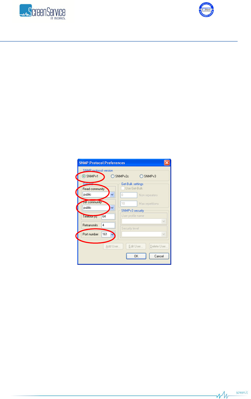
ISO 9001:2000 Cert. N°4500/1
Version 1.1 SDT_ARK6_User_Manual_ENG_vATSC Page 145 of 206
7.1 SNMP Protocol Preferences
Go to SNMP Protocol Preferences. The following parameters should be set in order to correctly configure
the SNMP Manager:
SNMP protocol version: SNMPv1/SNMPv2;
Read Community: the same of the one set in the Get field of Java interface, community section;
Set Community: the same of the one set in the Set field of Java interface, community section;
Timeout [s]: user defined;
Retransmits: user defined;
Port number: 161.
Next figure illustrates how to configure SNMP Protocol Preferences using MG_SOFT MIB Browser as an
example.
Figure 56. SNMP Protocol Preferences
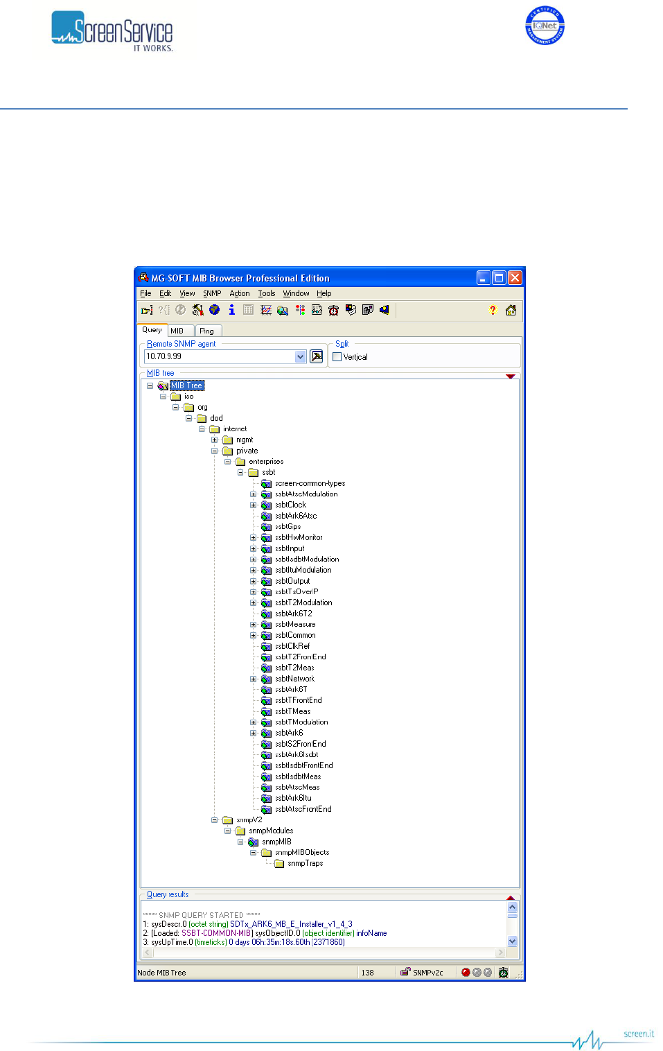
ISO 9001:2000 Cert. N°4500/1
Version 1.1 SDT_ARK6_User_Manual_ENG_vATSC Page 146 of 206
7.2 Monitoring
All status and setup information can be queried via SNMP. To get the setup and status information you
need a management system (or a special MIB browser).
Next figure, referring to MG-SOFT MIB Browser as an example, is a broad view of the ARK6 tree
structure.
Figure 57. ARK6 Tree Structure

ISO 9001:2000 Cert. N°4500/1
Version 1.1 SDT_ARK6_User_Manual_ENG_vATSC Page 147 of 206
The SSBT MIBs are:
ssbt-common-types: the MIB module housing SSBT Textual Conventions.
ssbtAtscModulation: the MIB module to manage the equipment configuration when operated
in ATSC mode.
ssbtClock: the MIB module for clock management.
ssbtArk6Atsc: the specific ARK6-ATSC MIB.
ssbtGps: the MIB module to monitor the collection of live data from the GPS receiver.
ssbtHwMonitor: The MIB module for HW monitor.
ssbtInput: the MIB module to monitor and manage inputs.
ssbtIsdbtModulation: the MIB module to manage the equipment configuration when operated
in ISDB-T mode.
ssbtItuModulation: the MIB module to manage the equipment configuration when operated in
ITU mode.
ssbtOutput: the MIB module to monitor and manage outputs.
ssbtTsOverIP: the MIB module to manage input and output GbE channels.
ssbtT2Modulation: the MIB module to manage the equipment configuration when operated in
DVB-T2 mode.
ssbtArk6T2: the specific ARK6-T2 MIB.
ssbtMeasure: the MIB module to manage and monitor ARK6 Measure board.
ssbtCommon: the MIB module housing SSBT common objects.
ssbtClkRef: the MIB module to set the frequency reference.
ssbtT2FrontEnd: the MIB module to manage and monitor information from DVB-T2 Front-End.
ssbtT2Meas: the MIB module to manage and monitor T2 information from Measure board.
ssbtNetwork: the MIB module for network monitoring.
ssbtArk6T: the specific ARK6-T MIB.
ssbtTFrontEnd: the MIB module to manage and monitor information from DVB-T Front-End.
ssbtTMeas: the MIB module to manage and monitor DVB-T information from Measure board.
ssbtTModulation: the MIB module to manage the equipment configuration when operated in
DVB-T mode.
ssbtArk6: the MIB module for the objects common to all ARK6 modes.
ssbtS2FrontEnd: the MIB module to manage and monitor information from DVB-S/S2 Front-End.
ssbtArk6Isdbt: the specific ARK6-ISDBT MIB.
ssbtIsdbtFrontEnd: the MIB module to manage and monitor information from ISDB-T Front-End.
ssbtIsdbtMeas: the MIB module to manage and monitor ISDB-T information from Measure
board.
ssbtAtscMeas: the MIB module to manage and monitor ATSC information from Measure board.
ssbtArk6Itu: the specific ARK6-ITU MIB.
ssbtAtscFrontEnd: the MIB module to manage and monitor information from ATSC Front-End.

ISO 9001:2000 Cert. N°4500/1
Version 1.1 SDT_ARK6_User_Manual_ENG_vATSC Page 148 of 206
Table 30. ARK6 SNMP Tree Structure
OID
Name
R/W
Description
1
iso
1.3
org
1.3.6
dod
1.3.6.1
internet
1.3.6.1.2
mgmt
1.3.6.1.2.1
mib-2
1.3.6.1.2.1.1
system
1.3.6.1.2.1.1.1
sysDescr
R
A textual description of the entity. This value includes the
full name and version identification of the system"
1.3.6.1.2.1.1.2
sysObjectID
R
1.3.6.1.2.1.1.3
sysUpTimeInstance
R
1.3.6.1.2.1.1.4
sysContact
R
1.3.6.1.2.1.1.5
sysName
R
Identification name of the equipment managed
1.3.6.1.2.1.1.6
sysLocation
R
1.3.6.1.2.1.1.7
sysServices
R
1.3.6.1.4
private
1.3.6.1.4.1
enterprise
1.3.6.1.4.1.21678
ssbt
1.3.6.1.4.1.21678.302
ssbtAtscModulation
1.3.6.1.4.1.21678.302.1
amMobileHandheld
1.3.6.1.4.1.21678.302.1.1
ammhPid
RW
ATSC M/H mode PID setting
1.3.6.1.4.1.21678.302.1.2
ammhEnable
RW
Enables ATSC M/H mode
1.3.6.1.4.1.21678.302.1.3
ammhFrameStatus
R
ATSC M/H frame alarm
1.3.6.1.4.1.21678.303
ssbtClock
1.3.6.1.4.1.21678.303.1
reference
1.3.6.1.4.1.21678.303.1.1
refClock
RW
Frequency reference selector
1.3.6.1.4.1.21678.303.2
gps
1.3.6.1.4.1.21678.303.2.1
satellites
1.3.6.1.4.1.21678.303.2.1.1
satVisible
R
Number of visible satellites.
1.3.6.1.4.1.21678.303.2.1.2
satTracked
R
Number of locked satellite.
1.3.6.1.4.1.21678.303.2.2
position
1.3.6.1.4.1.21678.303.2.2.1
positionLatitude
R
Latitude position [°]
1.3.6.1.4.1.21678.303.2.2.2
positionLongitude
R
Longitude position [°]
1.3.6.1.4.1.21678.303.2.3
utc

ISO 9001:2000 Cert. N°4500/1
Version 1.1 SDT_ARK6_User_Manual_ENG_vATSC Page 149 of 206
OID
Name
R/W
Description
1.3.6.1.4.1.21678.303.2.3.1
utcDate
R
UTC date and time as specified in SNMPv2-TC
1.3.6.1.4.1.21678.303.2.4
gpsLockStatus
1.3.6.1.4.1.21678.303.2.4.1
glsGps
R
GPS lock status derived from live data provided by the
GPS receiver
1.3.6.1.4.1.21678.303.3
ocxo
1.3.6.1.4.1.21678.303.3.1
fineFreqAdjust
RW
Enables the Holdover mechanism
1.3.6.1.4.1.21678.303.3.2
dataToFlash
R
Sets the timeout of the Holdover in hour
1.3.6.1.4.1.21678.303.3.3
ocxoLockStatus
1.3.6.1.4.1.21678.303.3.3.1
olsGps
R
OCXO locked to the external GPS reference
1.3.6.1.4.1.21678.303.3.3.2
ols10Mhz
R
OCXO locked to the external 10 MHz reference
1.3.6.1.4.1.21678.303.3.3.3
ols1Pps
R
OCXO locked to the external 1PPS reference
1.3.6.1.4.1.21678.303.4
holdover
1.3.6.1.4.1.21678.303.4.1
hEnable
RW
Enables the Holdover mechanism
1.3.6.1.4.1.21678.303.4.2
hTimeout
RW
Sets the timeout of the Holdover in hour
1.3.6.1.4.1.21678.303.4.3
hStatus
R
The status of the Holdover mechanism
1.3.6.1.4.1.21678.303.4.4
hTmoStatus
R
The countdown of the Holdover timeout expressed in
seconds
1.3.6.1.4.1.21678.306
ssbtHwMonitor
1.3.6.1.4.1.21678.306.1
reflexPower
R
Reflex power [dBm x 10]
1.3.6.1.4.1.21678.306.2
amplifierStatus
R
Amplifier status
1.3.6.1.4.1.21678.306.3
powerSupplies
1.3.6.1.4.1.21678.306.3.1
psNumber
R
The number of power supplies present on this system
1.3.6.1.4.1.21678.306.3.2
psTable
NA
1.3.6.1.4.1.21678.306.3.2.1
psEntry
1.3.6.1.4.1.21678.306.3.2.1.1
psIndex
R
1.3.6.1.4.1.21678.306.3.2.1.2
psDescr
R
Power supply description
1.3.6.1.4.1.21678.306.3.2.1.3
psVMeasUnit
R
Voltage unit of measurement
1.3.6.1.4.1.21678.306.3.2.1.4
psVoltage
R
Voltage indicator
1.3.6.1.4.1.21678.306.3.2.1.5
psCMeasUnit
R
Current unit of measurement
1.3.6.1.4.1.21678.306.3.2.1.6
psCurrent
R
Current indicator
1.3.6.1.4.1.21678.306.3.3
psRestart
W
Restarts the amplifier
1.3.6.1.4.1.21678.306.5
fans
1.3.6.1.4.1.21678.306.5.1
fansNumber
R
The number of fans present on this system
1.3.6.1.4.1.21678.306.5.2
fansTable
NA
1.3.6.1.4.1.21678.306.5.2.1
fansEntry
1.3.6.1.4.1.21678.306.5.2.1.1
fansIndex
R

ISO 9001:2000 Cert. N°4500/1
Version 1.1 SDT_ARK6_User_Manual_ENG_vATSC Page 150 of 206
OID
Name
R/W
Description
1.3.6.1.4.1.21678.306.5.2.1.2
fansDescr
R
Fan description
1.3.6.1.4.1.21678.306.5.2.1.3
fansMeasUnit
R
Fan speed unit of measurement
1.3.6.1.4.1.21678.306.5.2.1.4
fansSpeed
R
Fan speed
1.3.6.1.4.1.21678.306.6
temperatures
1.3.6.1.4.1.21678.306.6.1
tempNumber
R
The number of temperature sensors present on this
system
1.3.6.1.4.1.21678.306.6.2
tempTable
NA
1.3.6.1.4.1.21678.306.6.2.1
tempEntry
1.3.6.1.4.1.21678.306.6.2.1.1
tempIndex
R
1.3.6.1.4.1.21678.306.6.2.1.2
tempDescr
R
Temperature indicator description
1.3.6.1.4.1.21678.306.6.2.1.3
tempMeasUnit
R
Temperature unit of measurement
1.3.6.1.4.1.21678.306.6.2.1.4
tempLevel
R
Temperature indicator
1.3.6.1.4.1.21678.306.7
relays
1.3.6.1.4.1.21678.306.7.1
rlNumber
R
The number of relays present on this system
1.3.6.1.4.1.21678.306.7.2
rlTable
NA
1.3.6.1.4.1.21678.306.7.2.1
rlEntry
1.3.6.1.4.1.21678.306.7.2.1.1
rlIndex
R
1.3.6.1.4.1.21678.306.7.2.1.2
rlDescr
R
Relay description
1.3.6.1.4.1.21678.306.7.2.1.3
rlStatus
R
Relay status
1.3.6.1.4.1.21678.306.8
optocouplers
1.3.6.1.4.1.21678.306.8.1
optNumber
R
The number of optocouplers present on this system
1.3.6.1.4.1.21678.306.8.2
optTable
NA
1.3.6.1.4.1.21678.306.8.2.1
optEntry
1.3.6.1.4.1.21678.306.8.2.1.1
optIndex
R
1.3.6.1.4.1.21678.306.8.2.1.2
optDescr
R
Optocoupler description
1.3.6.1.4.1.21678.306.8.2.1.3
optStatus
R
Optocoupler status
1.3.6.1.4.1.21678.306.9
cpuFan
1.3.6.1.4.1.21678.306.9.1
cfNoFan
R
CPU Fan missing alarm status
1.3.6.1.4.1.21678.306.9.2
cfFanFault
R
CPU ventilation blocked alarm status
1.3.6.1.4.1.21678.307
ssbtInput
1.3.6.1.4.1.21678.307.1
inputSettings
1.3.6.1.4.1.21678.307.1.1
isT2InputManagement
1.3.6.1.4.1.21678.307.1.1.1
ist2imInputSel
RW
Input selector
1.3.6.1.4.1.21678.307.1.1.2
ist2imRfChannel
RW
Input channel selector
1.3.6.1.4.1.21678.307.1.1.3
ist2imRfFreqOff
RW
Input frequency offset expressed in Hz (1Hz steps, from -
200 kHz to 200 kHz)

ISO 9001:2000 Cert. N°4500/1
Version 1.1 SDT_ARK6_User_Manual_ENG_vATSC Page 151 of 206
OID
Name
R/W
Description
1.3.6.1.4.1.21678.307.1.2
isT2InputAutoswitch
1.3.6.1.4.1.21678.307.1.2.1
ist2iaEnable
RW
Enables the use of Input Autoswitch finite-state machine
1.3.6.1.4.1.21678.307.1.2.2
ist2iaState
R
Current state of the finite-state machine
1.3.6.1.4.1.21678.307.1.2.3
ist2iaActualInput
R
Shows the currently used input
1.3.6.1.4.1.21678.307.1.2.4
ist2iaPrimaryToSecondaryCounter
R
Primary to secondary input switch countdown expressed
in seconds
1.3.6.1.4.1.21678.307.1.2.5
ist2iaSecondaryToSecondaryCounter
R
Secondary to secondary input switch countdown
expressed in seconds
1.3.6.1.4.1.21678.307.1.2.6
ist2iaSecondaryToPrimaryCounter
R
Secondary to primary input switch countdown expressed
in seconds
1.3.6.1.4.1.21678.307.1.3
isTInputManagement
1.3.6.1.4.1.21678.307.1.3.1
istimInputSel
1.3.6.1.4.1.21678.307.1.3.1.1
istimisHpInput1
RW
High Priority input 1 selector
1.3.6.1.4.1.21678.307.1.3.1.2
istimisLpInput1
RW
Low Priority input 1 selector
1.3.6.1.4.1.21678.307.1.3.1.3
istimisHpInput2
RW
High Priority input 2 selector
1.3.6.1.4.1.21678.307.1.3.1.4
istimisLpInput2
RW
Low Priority input 2 selector
1.3.6.1.4.1.21678.307.1.3.2
istimRfChannel
RW
Input channel selector
1.3.6.1.4.1.21678.307.1.3.3
istimRfFreqOff
RW
Input frequency offset +/- 200 kHz (1Hz step)
1.3.6.1.4.1.21678.307.1.4
isTSeamlessSwitch
1.3.6.1.4.1.21678.307.1.4.1
istssHpInput
1.3.6.1.4.1.21678.307.1.4.1.1
istsshiForceInput
RW
Forces the use of the selected input as High Priority input
1.3.6.1.4.1.21678.307.1.4.1.2
istsshiPriorityInput
RW
Sets the priority input
1.3.6.1.4.1.21678.307.1.4.1.3
istsshiUsedInput
R
Shows the currently used input
1.3.6.1.4.1.21678.307.1.4.1.4
istsshiSwitchState
R
Shows the status of the Seamless Switch
1.3.6.1.4.1.21678.307.1.4.2
istssLpInput
1.3.6.1.4.1.21678.307.1.4.2.1
istsslpForceInput
RW
Forces the use of the selected input as Low Priority input
1.3.6.1.4.1.21678.307.1.4.2.2
istsslpPriorityInput
RW
Sets the priority input
1.3.6.1.4.1.21678.307.1.4.2.3
istsslpUsedInput
R
Shows the currently used input
1.3.6.1.4.1.21678.307.1.4.2.4
istsslpSwitchState
R
Shows the status of the Seamless Switch
1.3.6.1.4.1.21678.307.1.4.3
istssSeamlessAlarms
1.3.6.1.4.1.21678.307.1.4.3.1
istsssaInputNumber
R
The number of inputs depending on the Hierarchical
Mode and on the HP/LP Force Input selectors
1.3.6.1.4.1.21678.307.1.4.3.2
istsssaTable
NA
1.3.6.1.4.1.21678.307.1.4.3.2.1
istsssaEntry
1.3.6.1.4.1.21678.307.1.4.3.2.1.1
istsssaIndex
R
1.3.6.1.4.1.21678.307.1.4.3.2.1.2
istsssaInputDescr
R
Input description

ISO 9001:2000 Cert. N°4500/1
Version 1.1 SDT_ARK6_User_Manual_ENG_vATSC Page 152 of 206
OID
Name
R/W
Description
1.3.6.1.4.1.21678.307.1.4.3.2.1.3
istsssaPatCrcEn
RW
Enables the PAT CRC alarm bit in the Seamless Alarm
Mask
1.3.6.1.4.1.21678.307.1.4.3.2.1.4
istsssaMipCrcEn
RW
Enables the MIP CRC alarm bit in the Seamless Alarm
Mask
1.3.6.1.4.1.21678.307.1.4.3.2.1.5
istsssaSyncErrEn
RW
Enables the Sync alarm bit in the Seamless Alarm Mask
1.3.6.1.4.1.21678.307.1.4.3.2.1.6
istsssaPktJitterEn
RW
Enables the Packet Jitter alarm bit in the Seamless Alarm
Mask
1.3.6.1.4.1.21678.307.1.4.3.2.1.7
istsssaTransportErrEn
RW
Enables the Transport Error alarm bit in the Seamless
Alarm Mask
1.3.6.1.4.1.21678.307.1.4.3.2.1.8
istsssaAsiWordErrEn
RW
Enables the ASI Word Error alarm bit in the Seamless
Alarm Mask
1.3.6.1.4.1.21678.307.1.4.3.2.1.9
istsssaMipPriorityErrEn
RW
Enables the MIP Priority alarm bit in the Seamless Alarm
Mask
1.3.6.1.4.1.21678.307.1.4.3.2.1.10
istsssaNetworkDelay
R
Shows the Network Delay of the specific entry
1.3.6.1.4.1.21678.307.1.4.3.2.1.11
istsssaWatchdogErr
R
Input Watchdog alarm status
1.3.6.1.4.1.21678.307.1.4.3.2.1.12
istsssaLateMipErr
R
Late MIP alarm status
1.3.6.1.4.1.21678.307.1.4.3.2.1.13
istsssaNotValidErr
R
Invalid Input alarm status
1.3.6.1.4.1.21678.307.1.4.3.2.1.14
istsssaPatCrcErr
R
PAT CRC alarm status
1.3.6.1.4.1.21678.307.1.4.3.2.1.15
istsssaMipCrcErr
R
MIP CRC alarm status
1.3.6.1.4.1.21678.307.1.4.3.2.1.16
istsssaSyncErr
R
Transport Stream Sync Error alarm status
1.3.6.1.4.1.21678.307.1.4.3.2.1.17
istsssaPktJitterErr
R
Packet Jitter alarm status
1.3.6.1.4.1.21678.307.1.4.3.2.1.18
istsssaTransportErr
R
Transport Error alarm status
1.3.6.1.4.1.21678.307.1.4.3.2.1.19
istsssaAsiWordErr
R
ASI Word Error alarm status
1.3.6.1.4.1.21678.307.1.4.3.2.1.20
istsssaNetworkDelayErr
R
Network Delay alarm status
1.3.6.1.4.1.21678.307.1.4.3.2.1.21
istsssaMipPriorityErr
R
MIP Priority alarm status
1.3.6.1.4.1.21678.307.1.5
isIInputManagement
1.3.6.1.4.1.21678.307.1.5.1
isiimInputSel
RW
Input selector
1.3.6.1.4.1.21678.307.1.5.2
isiimRfChannel
RW
Input channel selector
1.3.6.1.4.1.21678.307.1.5.3
isiimRfFreqOff
RW
Input frequency offset expressed in Hz (1Hz steps, from -
200 kHz to 200 kHz)
1.3.6.1.4.1.21678.307.1.6
isAInputManagement
1.3.6.1.4.1.21678.307.1.6.1
isaimInputSel
RW
Input selector
1.3.6.1.4.1.21678.307.1.6.2
isaimRfChannel
RW
Input channel selector
1.3.6.1.4.1.21678.307.1.6.3
isaimRfFreqOff
RW
Input frequency offset +/- 200 kHz (1Hz step)
1.3.6.1.4.1.21678.307.1.7
isAInputAutoswitch
1.3.6.1.4.1.21678.307.1.7.1
isaiaEnable
RW
Enables the use of Input Autoswitch finite-state machine
1.3.6.1.4.1.21678.307.1.7.2
isaiaState
R
Current state of the finite-state machine

ISO 9001:2000 Cert. N°4500/1
Version 1.1 SDT_ARK6_User_Manual_ENG_vATSC Page 153 of 206
OID
Name
R/W
Description
1.3.6.1.4.1.21678.307.1.7.3
isaiaActualInput
R
Shows the currently used input
1.3.6.1.4.1.21678.307.1.7.4
isaiaPrimaryToSecondaryCounter
R
Primary to secondary input switch countdown expressed
in seconds
1.3.6.1.4.1.21678.307.1.7.5
isaiaSecondaryToSecondaryCounter
R
Secondary to secondary input switch countdown
expressed in seconds
1.3.6.1.4.1.21678.307.1.7.6
isaiaSecondaryToPrimaryCounter
R
Secondary to primary input switch countdown expressed
in seconds
1.3.6.1.4.1.21678.307.1.8
isItuInputManagement
1.3.6.1.4.1.21678.307.1.8.1
isituimInputSel
RW
Input selector
1.3.6.1.4.1.21678.307.1.8.2
isituimSdiAudioSel
RW
SDI audio selector
1.3.6.1.4.1.21678.307.1.9
isItuInputAutoswitch
1.3.6.1.4.1.21678.307.1.9.1
isituiaEnable
RW
Enables the use of Input Autoswitch finite-state machine
1.3.6.1.4.1.21678.307.1.9.2
isituiaState
R
Current state of the finite-state machine
1.3.6.1.4.1.21678.307.1.9.3
isituiaActualInput
R
Shows the currently used input
1.3.6.1.4.1.21678.307.1.9.4
isituiaPrimaryToSecondaryCounter
R
Primary to secondary input switch countdown expressed
in seconds
1.3.6.1.4.1.21678.307.1.9.5
isituiaSecondaryToSecondaryCounter
R
Secondary to secondary input switch countdown
expressed in seconds
1.3.6.1.4.1.21678.307.1.9.6
isituiaSecondaryToPrimaryCounter
R
Secondary to primary input switch countdown expressed
in seconds
1.3.6.1.4.1.21678.307.2
inputStatistics
1.3.6.1.4.1.21678.307.2.1
isNumber
R
Number of inputs
1.3.6.1.4.1.21678.307.2.2
isTable
NA
1.3.6.1.4.1.21678.307.2.2.1
isEntry
1.3.6.1.4.1.21678.307.2.2.1.1
isIndex
R
1.3.6.1.4.1.21678.307.2.2.1.2
isDescr
R
Input descriptor
1.3.6.1.4.1.21678.307.2.2.1.3
isType
R
Input type
1.3.6.1.4.1.21678.307.2.2.1.4
isWordRate
R
Input word rate
1.3.6.1.4.1.21678.307.2.2.1.5
isBitRate
R
Iinput bitrate
1.3.6.1.4.1.21678.307.2.2.1.6
isFiltered
R
Filtered bitrate
1.3.6.1.4.1.21678.307.2.2.1.7
isOverflow
R
Overflow
1.3.6.1.4.1.21678.307.2.2.1.8
isLock
R
Lock status
1.3.6.1.4.1.21678.307.2.2.1.9
isPckFormat
R
Packet format
1.3.6.1.4.1.21678.307.2.2.1.10
isCarrierDetect
R
Carrier detect indicator
1.3.6.1.4.1.21678.307.2.2.1.11
isErrors
R
Wrong bytes received
1.3.6.1.4.1.21678.307.2.2.1.12
isBypassEnable
RW
Cable equalizer bypass enable
1.3.6.1.4.1.21678.307.2.3
sdi

ISO 9001:2000 Cert. N°4500/1
Version 1.1 SDT_ARK6_User_Manual_ENG_vATSC Page 154 of 206
OID
Name
R/W
Description
1.3.6.1.4.1.21678.307.2.3.1
sdiNumber
R
Number of SDI inputs.
1.3.6.1.4.1.21678.307.2.3.2
sdiTable
NA
1.3.6.1.4.1.21678.307.2.3.2.1
sdiEntry
1.3.6.1.4.1.21678.307.2.3.2.1.1
sdiIndex
R
Index of the specific entry
1.3.6.1.4.1.21678.307.2.3.2.1.2
sdiDescr
R
SDI input description
1.3.6.1.4.1.21678.307.2.3.2.1.3
sdiLock
R
SDI lock status
1.3.6.1.4.1.21678.307.2.3.2.1.4
sdiCarrierDetectAlarm
R
SDI carrier detect alarm
1.3.6.1.4.1.21678.307.2.3.2.1.5
sdiCh12Present
R
SDI audio channels 1-2 are present
1.3.6.1.4.1.21678.307.2.3.2.1.6
sdiCh1Level
R
SDI audio channel 1 level expressed in dBFS (-128
stands for muted or no signal)
1.3.6.1.4.1.21678.307.2.3.2.1.7
sdiCh2Level
R
SDI audio channel 2 level expressed in dBFS (-128
stands for muted or no signal)
1.3.6.1.4.1.21678.307.2.3.2.1.8
sdiCh34Present
R
SDI audio channels 3-4 are present
1.3.6.1.4.1.21678.307.2.3.2.1.9
sdiCh3Level
R
SDI audio channel 3 level expressed in dBFS (-128
stands for muted or no signal)
1.3.6.1.4.1.21678.307.2.3.2.1.10
sdiCh4Level
R
SDI audio channel 4 level expressed in dBFS (-128
stands for muted or no signal)
1.3.6.1.4.1.21678.307.2.3.2.1.11
sdiStandard
R
SDI standard
1.3.6.1.4.1.21678.307.2.3.2.1.12
sdiBypassEnable
RW
Cable equalizer bypass enable
1.3.6.1.4.1.21678.307.2.4
cvbs
1.3.6.1.4.1.21678.307.2.4.1
cvbsNumber
R
Number of CVBS inputs.
1.3.6.1.4.1.21678.307.2.4.2
cvbsTable
NA
1.3.6.1.4.1.21678.307.2.4.2.1
cvbsEntry
1.3.6.1.4.1.21678.307.2.4.2.1.1
cvbsIndex
R
Index of the specific entry
1.3.6.1.4.1.21678.307.2.4.2.1.2
cvbsDescr
R
Input description
1.3.6.1.4.1.21678.307.2.4.2.1.3
cvbsLock
R
Input lock status
1.3.6.1.4.1.21678.307.2.4.2.1.4
cvbsColorSub
R
Color subcarrier lock status
1.3.6.1.4.1.21678.307.2.4.2.1.5
cvbsVerticalLock
R
Vertical lock status
1.3.6.1.4.1.21678.307.2.4.2.1.6
cvbsHorizontalLock
R
Horizontal lock status
1.3.6.1.4.1.21678.307.2.4.2.1.7
cvbsStandard
R
CVBS input standard
1.3.6.1.4.1.21678.307.2.4.2.1.8
cvbsFrameRate
R
Frame rate
1.3.6.1.4.1.21678.307.2.4.2.1.9
cvbsADPalCompensation
RW
Enables the A/D PAL Compensation
1.3.6.1.4.1.21678.307.3
t2FrontEnd
1.3.6.1.4.1.21678.307.3.1
t2feStatistics
1.3.6.1.4.1.21678.307.3.1.1
t2fesRxLevel
R
Input RX level 127: over input -128: low power -
63...62: power expressed in dB
1.3.6.1.4.1.21678.307.3.1.2
t2fesCarrierOffset
R
Input carrier offset

ISO 9001:2000 Cert. N°4500/1
Version 1.1 SDT_ARK6_User_Manual_ENG_vATSC Page 155 of 206
OID
Name
R/W
Description
1.3.6.1.4.1.21678.307.3.1.3
t2fesIfAgc
R
Input IF AGC level
1.3.6.1.4.1.21678.307.3.1.4
t2fesRfAgc
R
Input RF AGC level
1.3.6.1.4.1.21678.307.3.1.5
t2fesTsLock
R
Demodulated TS Lock
1.3.6.1.4.1.21678.307.3.1.6
t2fesSyncStat
R
Sync statistics
1.3.6.1.4.1.21678.307.3.1.7
t2fesMer
R
Input MER [dBx1e3]
1.3.6.1.4.1.21678.307.3.1.8
t2fesSnr
R
Input SNR [dBx1e3]
1.3.6.1.4.1.21678.307.3.1.9
t2fesPreLdpcBer
R
Input Pre LDPC BER [1e7]
1.3.6.1.4.1.21678.307.3.1.10
t2fesPostBchFer
R
Input Post BCH FER [1e6]
1.3.6.1.4.1.21678.307.3.1.11
t2fesPreBchBer
R
Input Pre BCH BER [1e9]
1.3.6.1.4.1.21678.307.3.1.12
t2fesDemodPpm
R
Demodulated PPM [ppmx1e2]
1.3.6.1.4.1.21678.307.3.1.13
t2fesSignalQuality
R
Signal quality [%]
1.3.6.1.4.1.21678.307.3.1.14
t2fesBitrate
R
Expected bitrate
1.3.6.1.4.1.21678.307.3.1.15
t2fesLdpcIter
R
LDPC iterations per minute
1.3.6.1.4.1.21678.307.3.2
t2feL1Pre
1.3.6.1.4.1.21678.307.3.2.1
t2feL1PreType
R
Input stream type
1.3.6.1.4.1.21678.307.3.2.2
t2feL1PreBwt
R
BWT extension indicator
1.3.6.1.4.1.21678.307.3.2.3
t2feL1PreS1
R
S1 field
1.3.6.1.4.1.21678.307.3.2.4
t2feL1PreS2
R
S2 field
1.3.6.1.4.1.21678.307.3.2.5
t2feL1PreFftSize
R
FFT size
1.3.6.1.4.1.21678.307.3.2.6
t2feL1PreMixed
R
Mixed indicator
1.3.6.1.4.1.21678.307.3.2.7
t2feL1PreL1Repeat
R
L1 repeat enable flag
1.3.6.1.4.1.21678.307.3.2.8
t2feL1PreGuardInterval
R
Guard Interval
1.3.6.1.4.1.21678.307.3.2.9
t2feL1PrePapr
R
PAPR
1.3.6.1.4.1.21678.307.3.2.10
t2feL1PreL1Mod
R
L1 modulation scheme
1.3.6.1.4.1.21678.307.3.2.11
t2feL1PreL1CodeRate
R
L1 code rate
1.3.6.1.4.1.21678.307.3.2.12
t2feL1PreL1Fec
R
L1 FEC Type
1.3.6.1.4.1.21678.307.3.2.13
t2feL1PreL1PostSize
R
L1 Post Size
1.3.6.1.4.1.21678.307.3.2.14
t2feL1PreL1PostInfoSize
R
L1 Post Info Size
1.3.6.1.4.1.21678.307.3.2.15
t2feL1PrePilotPattern
R
Pilot Pattern
1.3.6.1.4.1.21678.307.3.2.16
t2feL1PreTxIdAvailability
R
TX Id
1.3.6.1.4.1.21678.307.3.2.17
t2feL1PreCellId
R
Cell Id
1.3.6.1.4.1.21678.307.3.2.18
t2feL1PreT2NetworkId
R
T2 Network Id
1.3.6.1.4.1.21678.307.3.2.19
t2feL1PreT2SystemId
R
T2 System Id
1.3.6.1.4.1.21678.307.3.2.20
t2feL1PreNumT2Frames
R
Number of T2 frames
1.3.6.1.4.1.21678.307.3.2.21
t2feL1PreNumDataSymb
R
Number of data symbols
1.3.6.1.4.1.21678.307.3.2.22
t2feL1PreRegenFlag
R
Regeneration count indicator

ISO 9001:2000 Cert. N°4500/1
Version 1.1 SDT_ARK6_User_Manual_ENG_vATSC Page 156 of 206
OID
Name
R/W
Description
1.3.6.1.4.1.21678.307.3.2.23
t2feL1PreL1PostExt
R
L1 Post extension enabled
1.3.6.1.4.1.21678.307.3.2.24
t2feL1PreRfIndex
R
The current RF index
1.3.6.1.4.1.21678.307.3.3
t2feL1Post
1.3.6.1.4.1.21678.307.3.3.1
t2feL1PostSubSliceNum
R
Number of sub-slices per frame
1.3.6.1.4.1.21678.307.3.3.2
t2feL1PostFefType
R
The type of the associated FEF part
1.3.6.1.4.1.21678.307.3.3.3
t2feL1PostFefLength
R
FEF length
1.3.6.1.4.1.21678.307.3.3.4
t2feL1PostFefInterval
R
FEF interval
1.3.6.1.4.1.21678.307.3.3.5
t2feL1PostAux
1.3.6.1.4.1.21678.307.3.3.5.1
t2feL1PostAuxNum
R
Number of AUXs
1.3.6.1.4.1.21678.307.3.3.5.2
t2feL1PostAuxTable
NA
1.3.6.1.4.1.21678.307.3.3.5.2.1
t2feL1PostAuxEntry
1.3.6.1.4.1.21678.307.3.3.5.2.1.1
t2feL1PostAuxIndex
R
1.3.6.1.4.1.21678.307.3.3.5.2.1.2
t2feL1PostAuxStreamType
R
The type of the current auxiliary stream
1.3.6.1.4.1.21678.307.3.3.5.2.1.3
t2feL1PostAuxPrivateConf
R
RFU
1.3.6.1.4.1.21678.307.3.3.6
t2feL1PostRf
1.3.6.1.4.1.21678.307.3.3.6.1
t2feL1PostNumRf
R
The number of RF frequencies in use
1.3.6.1.4.1.21678.307.3.3.6.2
t2feL1PostRfTable
NA
1.3.6.1.4.1.21678.307.3.3.6.2.1
t2feL1PostRfEntry
1.3.6.1.4.1.21678.307.3.3.6.2.1.1
t2feL1PostRfIndex
R
1.3.6.1.4.1.21678.307.3.3.6.2.1.2
t2feL1PostRfIdx
R
RF index
1.3.6.1.4.1.21678.307.3.3.6.2.1.3
t2feL1PostFrequency
R
Frequency
1.3.6.1.4.1.21678.307.3.3.7
t2feL1PostPlp
1.3.6.1.4.1.21678.307.3.3.7.1
t2feL1PostPlpNum
R
Number of PLPs
1.3.6.1.4.1.21678.307.3.3.7.2
t2feL1PostPlpTable
NA
1.3.6.1.4.1.21678.307.3.3.7.2.1
t2feL1PostPlpEntry
1.3.6.1.4.1.21678.307.3.3.7.2.1.1
t2feL1PostPlpIndex
R
1.3.6.1.4.1.21678.307.3.3.7.2.1.2
t2feL1PostPlpId
R
PLP ID
1.3.6.1.4.1.21678.307.3.3.7.2.1.3
t2feL1PostPlpType
R
PLP type
1.3.6.1.4.1.21678.307.3.3.7.2.1.4
t2feL1PostPlpPayloadType
R
PLP payload type
1.3.6.1.4.1.21678.307.3.3.7.2.1.5
t2feL1PostFfFlag
R
FF flag
1.3.6.1.4.1.21678.307.3.3.7.2.1.6
t2feL1PostFirstRfIdx
R
First RF index
1.3.6.1.4.1.21678.307.3.3.7.2.1.7
t2feL1PostFirstFrameIdx
R
First frame index
1.3.6.1.4.1.21678.307.3.3.7.2.1.8
t2feL1PostGroupId
R
PLP group id
1.3.6.1.4.1.21678.307.3.3.7.2.1.9
t2feL1PostPlpCod
R
The code rate used by the associated PLP
1.3.6.1.4.1.21678.307.3.3.7.2.1.10
t2feL1PostPlpMod
R
The modulation used by the associated PLP
1.3.6.1.4.1.21678.307.3.3.7.2.1.11
t2feL1PostPlpRotation
R
DVBT2 rotated constellation indicator

ISO 9001:2000 Cert. N°4500/1
Version 1.1 SDT_ARK6_User_Manual_ENG_vATSC Page 157 of 206
OID
Name
R/W
Description
1.3.6.1.4.1.21678.307.3.3.7.2.1.12
t2feL1PostPlpFec
R
The FEC type used by the associated PLP
1.3.6.1.4.1.21678.307.3.3.7.2.1.13
t2feL1PostNumBlocksMax
R
Maximum number of PLP blocks
1.3.6.1.4.1.21678.307.3.3.7.2.1.14
t2feL1PostFrameInterval
R
Frame interval
1.3.6.1.4.1.21678.307.3.3.7.2.1.15
t2feL1PostTimeIntLength
R
Time interleaving length
1.3.6.1.4.1.21678.307.3.3.7.2.1.16
t2feL1PostTimeIntType
R
Time interleaving type
1.3.6.1.4.1.21678.307.3.3.7.2.1.17
t2feL1PostInbandA
R
In-band A flag
1.3.6.1.4.1.21678.307.3.3.7.2.1.18
t2feL1PostInbandB
R
In-band B flag
1.3.6.1.4.1.21678.307.3.3.7.2.1.19
t2feL1PostPlpMode
R
PLP mode
1.3.6.1.4.1.21678.307.3.3.7.2.1.20
t2feL1PostStaticFlag
R
Static flag
1.3.6.1.4.1.21678.307.3.3.7.2.1.21
t2feL1PostStaticPaddFlag
R
Static padding flag
1.3.6.1.4.1.21678.307.4
tFrontEnd
1.3.6.1.4.1.21678.307.4.1
tfeStatistics
1.3.6.1.4.1.21678.307.4.1.1
tfesRxLevel
R
Input RX level 127: over input -128: low power -
63...62: power expressed in dB
1.3.6.1.4.1.21678.307.4.1.2
tfesCarrierOffset
R
Input carrier offset
1.3.6.1.4.1.21678.307.4.1.3
tfesIfAgc
R
Input IF AGC level
1.3.6.1.4.1.21678.307.4.1.4
tfesRfAgc
R
Input RF AGC level
1.3.6.1.4.1.21678.307.4.1.5
tfesTsLock
R
Demodulated TS Lock
1.3.6.1.4.1.21678.307.4.1.6
tfesSyncStat
R
Sync statistics
1.3.6.1.4.1.21678.307.4.1.7
tfesMer
R
Input MER [dBx1e3]
1.3.6.1.4.1.21678.307.4.1.8
tfesSnr
R
Input SNR [dBx1e3]
1.3.6.1.4.1.21678.307.4.1.9
tfesPreVitBer
R
Input Pre Viterbi BER [1e7]
1.3.6.1.4.1.21678.307.4.1.10
tfesPreRsBer
R
Input Pre RS BER [1e7]
1.3.6.1.4.1.21678.307.4.1.11
tfesRsErrCount
R
Input RS errors count detected by the RS decoder over 1
second
1.3.6.1.4.1.21678.307.4.1.12
tfesDemodPpm
R
Demodulated PPM [ppmx1e2]
1.3.6.1.4.1.21678.307.4.1.13
tfesSignalQuality
R
Signal quality [%]
1.3.6.1.4.1.21678.307.4.1.14
tfesBitrate
R
Expected bitrate
1.3.6.1.4.1.21678.307.4.2
tfeDemodParams
1.3.6.1.4.1.21678.307.4.2.1
tfedpConstellation
R
Constellation for current modulation scheme
1.3.6.1.4.1.21678.307.4.2.2
tfedpHierMode
R
Hierarchy information for current modulation scheme
1.3.6.1.4.1.21678.307.4.2.3
tfedpHpCodeRate
R
High Priority Code Rate
1.3.6.1.4.1.21678.307.4.2.4
tfedpLpCodeRate
R
Low Priority Code Rate
1.3.6.1.4.1.21678.307.4.2.5
tfedpFft
R
FFT size
1.3.6.1.4.1.21678.307.4.2.6
tfedpGuardInterval
R
Guard interval
1.3.6.1.4.1.21678.307.4.2.7
tfedpCelllId
R
Cell identifier

ISO 9001:2000 Cert. N°4500/1
Version 1.1 SDT_ARK6_User_Manual_ENG_vATSC Page 158 of 206
OID
Name
R/W
Description
1.3.6.1.4.1.21678.307.5
s2FrontEnd
1.3.6.1.4.1.21678.307.5.1
s2feSettngs
1.3.6.1.4.1.21678.307.5.1.1
s2feFrequency
RW
Frequency [MHz]
1.3.6.1.4.1.21678.307.5.1.2
s2feSymbolRate
RW
Symbol Rate [KBaud]
1.3.6.1.4.1.21678.307.5.1.3
s2fePolarization
RW
Polarization
1.3.6.1.4.1.21678.307.5.1.4
s2feIsiA
RW
Input Stream Identifier A
1.3.6.1.4.1.21678.307.5.1.5
s2feIsiB
RW
Input Stream Identifier B
1.3.6.1.4.1.21678.307.5.1.6
s2fePls
1.3.6.1.4.1.21678.307.5.1.6.1
s2fepMode
RW
Mode selector
1.3.6.1.4.1.21678.307.5.1.6.2
s2fepN0
RW
PLS number 0 setting
1.3.6.1.4.1.21678.307.5.1.6.3
s2fepN1
RW
PLS number 1 setting
1.3.6.1.4.1.21678.307.5.1.6.4
s2fepN2
RW
PLS number 2 setting
1.3.6.1.4.1.21678.307.5.2
s2feDemodParams
1.3.6.1.4.1.21678.307.5.2.1
s2fedpRxLevel
R
Input RX level [dBm]
1.3.6.1.4.1.21678.307.5.2.2
s2fedpLock
R
Transponder lock status
1.3.6.1.4.1.21678.307.5.2.3
s2fedpStandard
R
Input standard
1.3.6.1.4.1.21678.307.5.2.4
s2fedpRxModCode
R
Modulation mode
1.3.6.1.4.1.21678.307.5.2.5
s2fedpBand
R
Band
1.3.6.1.4.1.21678.307.5.2.6
s2fedpMode
R
Mode
1.3.6.1.4.1.21678.307.5.2.7
s2fedpSnr
R
S/N level [dB * 10]
1.3.6.1.4.1.21678.307.5.2.8
s2fedpPilots
R
Pilots
1.3.6.1.4.1.21678.307.5.2.9
s2fedpRollOff
R
Roll off
1.3.6.1.4.1.21678.307.5.2.10
s2fedpConstellation
R
Constellation
1.3.6.1.4.1.21678.307.5.2.11
s2fedpBer
R
Bit Error Rate (* 10^7)
1.3.6.1.4.1.21678.307.6
isdbtFrontEnd
1.3.6.1.4.1.21678.307.6.1
ifeStatistics
1.3.6.1.4.1.21678.307.6.1.1
ifesRxLevel
R
Input RX level 127: over input -128: low power -
63...62: power expressed in dB
1.3.6.1.4.1.21678.307.6.1.2
ifesIfLevel
R
Input IF level
1.3.6.1.4.1.21678.307.6.1.3
ifesIfAgcDac
R
IF AGC output DAC value
1.3.6.1.4.1.21678.307.6.1.4
ifesDemState
R
The state of the sequencer
1.3.6.1.4.1.21678.307.6.1.5
ifesMode
R
Input mode
1.3.6.1.4.1.21678.307.6.1.6
ifesGuardInterval
R
Input guard interval
1.3.6.1.4.1.21678.307.6.1.7
ifesSTRFreqErr
R
Frequency error detected by symbol timing recovery [Hz]
1.3.6.1.4.1.21678.307.6.1.8
ifesCRFreqErr
R
Frequency error detected by carrier recovery [kHz]
1.3.6.1.4.1.21678.307.6.1.9
ifesCN
R
Estimated Carrier to Noise ratio (dB x 10)

ISO 9001:2000 Cert. N°4500/1
Version 1.1 SDT_ARK6_User_Manual_ENG_vATSC Page 159 of 206
OID
Name
R/W
Description
1.3.6.1.4.1.21678.307.6.2
ifeLayerStatistics
1.3.6.1.4.1.21678.307.6.2.1
ifelsNumber
R
The number of Layers
1.3.6.1.4.1.21678.307.6.2.2
ifelsTable
NA
1.3.6.1.4.1.21678.307.6.2.2.1
ifelsEntry
1.3.6.1.4.1.21678.307.6.2.2.1.1
ifelsIndex
R
1.3.6.1.4.1.21678.307.6.2.2.1.2
ifelsDescr
R
Layer description
1.3.6.1.4.1.21678.307.6.2.2.1.3
ifelsMod
R
Modulation scheme
1.3.6.1.4.1.21678.307.6.2.2.1.4
ifelsCodeRate
R
Code rate
1.3.6.1.4.1.21678.307.6.2.2.1.5
ifelsTILength
R
Time Interleaving length
1.3.6.1.4.1.21678.307.6.2.2.1.6
ifelsSegNum
R
Number of segments
1.3.6.1.4.1.21678.307.6.2.2.1.7
ifelsMer
R
MER [dB] (* 10)
1.3.6.1.4.1.21678.307.6.2.2.1.8
ifelsPreVitBer
R
Pre-Viterbi BER (* 10^9)
1.3.6.1.4.1.21678.307.6.2.2.1.9
ifelsPostVitBer
R
Post-Viterbi BER (* 10^9)
1.3.6.1.4.1.21678.307.6.2.2.1.10
ifelsPktErrRate
R
Packet Error Rate (* 10^9)
1.3.6.1.4.1.21678.307.7
atscFrontEnd
1.3.6.1.4.1.21678.307.7.1
afeStatistics
1.3.6.1.4.1.21678.307.7.1.1
afesFrequencyOffset
R
Input carrier offset
1.3.6.1.4.1.21678.307.7.1.2
afesDemodStatus
R
VSB demodulation status
1.3.6.1.4.1.21678.307.7.1.3
afesEqStatus
R
Equalizer status
1.3.6.1.4.1.21678.307.7.1.4
afesDemLock
R
Demodulator lock status
1.3.6.1.4.1.21678.307.7.1.5
afesAgcLock
R
Digital AGC lock status
1.3.6.1.4.1.21678.307.7.1.6
afesFrameLock
R
Frame lock status
1.3.6.1.4.1.21678.307.7.1.7
afesCarrierFreqLoopLock
R
Carrier frequency loop lock status
1.3.6.1.4.1.21678.307.7.1.8
afesTimingFreqLoopLock
R
Timing frequency loop lock status
1.3.6.1.4.1.21678.307.7.1.9
afesSnr
R
Signal to Noise Ratio [dB]
1.3.6.1.4.1.21678.307.7.1.10
afesSer
R
Segment Error Rate
1.3.6.1.4.1.21678.307.7.1.11
afesBer
R
Bit Error Rate
1.3.6.1.4.1.21678.308
ssbtIsdbtModulation
1.3.6.1.4.1.21678.308.1
imSettings
1.3.6.1.4.1.21678.308.1.1
imsIipStatus
1.3.6.1.4.1.21678.308.1.1.1
imsisValid
R
Input IIP valid
1.3.6.1.4.1.21678.308.1.1.2
imsisAlarm
R
Input IIP alarm
1.3.6.1.4.1.21678.308.1.2
imsNetworkMode
RW
Transmitter network mode selector
1.3.6.1.4.1.21678.308.1.3
imsEquipmentId
RW
Equipment ID
1.3.6.1.4.1.21678.308.1.4
imsDefIip
R
Equipment ID found in IIP
1.3.6.1.4.1.21678.308.1.5
imsNetworkDelay
R
Network delay [100ns]

ISO 9001:2000 Cert. N°4500/1
Version 1.1 SDT_ARK6_User_Manual_ENG_vATSC Page 160 of 206
OID
Name
R/W
Description
1.3.6.1.4.1.21678.308.1.6
imsEWS
1.3.6.1.4.1.21678.308.1.6.1
imsewsEnable
RW
Enables the local editing of the Emergency switch on
control flag
1.3.6.1.4.1.21678.308.1.6.2
imsewsSetting
RW
Sets the Emergency switch on control flag
1.3.6.1.4.1.21678.308.1.7
imsLayersMonitor
1.3.6.1.4.1.21678.308.1.7.1
imslmNumber
R
The number of Layers
1.3.6.1.4.1.21678.308.1.7.2
imslmTable
NA
1.3.6.1.4.1.21678.308.1.7.2.1
imslmEntry
1.3.6.1.4.1.21678.308.1.7.2.1.1
imslmIndex
R
1.3.6.1.4.1.21678.308.1.7.2.1.2
imslmDescr
R
Layer description
1.3.6.1.4.1.21678.308.1.7.2.1.3
imslmPktXFrame
R
Number of packets per frame
1.3.6.1.4.1.21678.308.1.7.2.1.4
imslmOverflow
R
Overflow
1.3.6.1.4.1.21678.308.1.7.2.1.5
imslmUnderflow
R
Underflow
1.3.6.1.4.1.21678.308.2
imIipParams
1.3.6.1.4.1.21678.308.2.1
imipMode
R
IIP modulator mode.
1.3.6.1.4.1.21678.308.2.2
imipGuardInterval
R
IIP modulator guard interval.
1.3.6.1.4.1.21678.308.2.3
imipUsePartialReceptionFlag
R
IIP modulator use the Partial Reception Flag.
1.3.6.1.4.1.21678.308.2.4
imipMaxDelay
R
IIP maximum delay [100 ns].
1.3.6.1.4.1.21678.308.2.5
imipSyncId
R
IIP modulator use the Synchronization ID.
1.3.6.1.4.1.21678.308.2.6
imipStaticDelay
R
IIP modulator use the Time Reference.
1.3.6.1.4.1.21678.308.2.7
imipTimeOffset
R
IIP time offset [100 ns].
1.3.6.1.4.1.21678.308.2.8
imipLayers
1.3.6.1.4.1.21678.308.2.8.1
imiplNumber
R
The number of Layers
1.3.6.1.4.1.21678.308.2.8.2
imiplTable
NA
1.3.6.1.4.1.21678.308.2.8.2.1
imiplEntry
1.3.6.1.4.1.21678.308.2.8.2.1.1
imiplIndex
R
1.3.6.1.4.1.21678.308.2.8.2.1.2
imiplDescr
R
Layer description
1.3.6.1.4.1.21678.308.2.8.2.1.3
imiplMod
R
Modulation scheme
1.3.6.1.4.1.21678.308.2.8.2.1.4
imiplCodeRate
R
Code rate of inner code
1.3.6.1.4.1.21678.308.2.8.2.1.5
imiplTILength
R
Time Interleaving length
1.3.6.1.4.1.21678.308.2.8.2.1.6
imiplSegNum
R
Number of segments
1.3.6.1.4.1.21678.308.3
imLocalParams
1.3.6.1.4.1.21678.308.3.1
imlpMode
RW
Modulator mode.
1.3.6.1.4.1.21678.308.3.2
imlpGuardInterval
RW
Modulator guard interval.
1.3.6.1.4.1.21678.308.3.3
imlpUsePartialReceptionFlag
RW
Use the Partial Reception Flag.
1.3.6.1.4.1.21678.308.3.4
imlpUserDelay
RW
User delay [100 ns].

ISO 9001:2000 Cert. N°4500/1
Version 1.1 SDT_ARK6_User_Manual_ENG_vATSC Page 161 of 206
OID
Name
R/W
Description
1.3.6.1.4.1.21678.308.3.5
imlpLayers
1.3.6.1.4.1.21678.308.3.5.1
imlplNumber
R
The number of Layers
1.3.6.1.4.1.21678.308.3.5.2
imlplTable
NA
1.3.6.1.4.1.21678.308.3.5.2.1
imlplEntry
1.3.6.1.4.1.21678.308.3.5.2.1.1
imlplIndex
R
1.3.6.1.4.1.21678.308.3.5.2.1.2
imlplDescr
RW
Layer description
1.3.6.1.4.1.21678.308.3.5.2.1.3
imlplMod
RW
Modulation scheme
1.3.6.1.4.1.21678.308.3.5.2.1.4
imlplCodeRate
RW
Code rate of inner code
1.3.6.1.4.1.21678.308.3.5.2.1.5
imlplTILength
RW
Time Interleaving length
1.3.6.1.4.1.21678.308.3.5.2.1.6
imlplSegNum
RW
Number of segments
1.3.6.1.4.1.21678.308.4
imCurrentParams
1.3.6.1.4.1.21678.308.4.1
imcpMode
R
Current modulator mode.
1.3.6.1.4.1.21678.308.4.2
imcpGuardInterval
R
Current modulator guard interval.
1.3.6.1.4.1.21678.308.4.3
imcpUsePartialReceptionFlag
R
Use the Partial Reception Flag.
1.3.6.1.4.1.21678.308.4.4
imcpSystemDelay
R
Current system delay [100 ns].
1.3.6.1.4.1.21678.308.4.5
imcpLayers
1.3.6.1.4.1.21678.308.4.5.1
imcplNumber
R
The number of Layers
1.3.6.1.4.1.21678.308.4.5.2
imcplTable
NA
1.3.6.1.4.1.21678.308.4.5.2.1
imcplEntry
1.3.6.1.4.1.21678.308.4.5.2.1.1
imcplIndex
R
1.3.6.1.4.1.21678.308.4.5.2.1.2
imcplDescr
R
Layer description
1.3.6.1.4.1.21678.308.4.5.2.1.3
imcplMod
R
Modulation scheme
1.3.6.1.4.1.21678.308.4.5.2.1.4
imcplCodeRate
R
Code rate of inner code
1.3.6.1.4.1.21678.308.4.5.2.1.5
imcplTILength
R
Time Interleaving length
1.3.6.1.4.1.21678.308.4.5.2.1.6
imcplSegNum
R
Number of segments
1.3.6.1.4.1.21678.309
ssbtItuModulation
1.3.6.1.4.1.21678.309.1
itumVideoSettings
1.3.6.1.4.1.21678.309.1.1
itumvsWhitelevel
RW
White level [%] (range 10 to 22) = [(x*0.05) + 10] (x:
range 0 to 240)
1.3.6.1.4.1.21678.309.1.2
itumvsSynchAmplitude
RW
Synch Amplitude [%] (range: 22 to 27,5) = [(x*0.05) + 20]
(x: range 40 to 150)
1.3.6.1.4.1.21678.309.1.3
itumvsPedesLevel
RW
Pedes level [%] (range: 0 to 7) = (x*0.05) (x: range 0 to
140)
1.3.6.1.4.1.21678.309.2
itumAudioSettings
1.3.6.1.4.1.21678.309.2.1
itumasDeviation
RW
Audio deviation level
1.3.6.1.4.1.21678.309.2.2
itumasSoundSystem
RW
Sound System selector

ISO 9001:2000 Cert. N°4500/1
Version 1.1 SDT_ARK6_User_Manual_ENG_vATSC Page 162 of 206
OID
Name
R/W
Description
1.3.6.1.4.1.21678.309.2.3
itumasCarrierLevel1
RW
Carrier Level 1 [dB] (range: -7 to -22) = [-1* (x/10)] (range
70 to 220)
1.3.6.1.4.1.21678.309.2.4
itumasCarrierLevel2
RW
Carrier Level 2 [dB] (range: -7 to -22) = [-1* (x/10)] (range
70 to 220)
1.3.6.1.4.1.21678.309.2.5
itumasEmphasis
R
Emphasis monitor
1.3.6.1.4.1.21678.309.2.6
itumasType
RW
Selects the audio type
1.3.6.1.4.1.21678.309.3
itumGroupDelay
1.3.6.1.4.1.21678.309.3.1
itumgdCurveSelector
RW
Mode selector for group delay filter
1.3.6.1.4.1.21678.310
ssbtOutput
1.3.6.1.4.1.21678.310.1
outputSettings
1.3.6.1.4.1.21678.310.1.1
osOutputManagement
1.3.6.1.4.1.21678.310.1.1.3
osomOutPower
RW
Output power
1.3.6.1.4.1.21678.310.1.1.4
osomRflManagement
1.3.6.1.4.1.21678.310.1.1.4.1
osomrmNumberAttempts
RW
Number of attempts to restore the system after a Reflex
Power warning
1.3.6.1.4.1.21678.310.1.1.4.2
osomrmStatus
R
Reflex Power status
1.3.6.1.4.1.21678.310.1.1.4.3
osomrmRflHigh
R
Shows if the Reflex Power High goes over the alarm
threshold
1.3.6.1.4.1.21678.310.1.1.4.4
osomrmCurrNumAttempt
R
Shows the current number of attemp to restore the
system after a Reflex Power warning
1.3.6.1.4.1.21678.310.1.1.4.5
osomrmAttemptTimeout
R
Shows the coutdown expressed in seconds between two
attemps
1.3.6.1.4.1.21678.310.1.1.4.6
osomrmReset
W
Resets the output amplifier stage once the device is in
Reflex Power Alarm
1.3.6.1.4.1.21678.310.1.1.4.7
osomrmResetTimeout
R
Shows the coutdown expressed in seconds to come back
from Warning to Ok state
1.3.6.1.4.1.21678.310.1.1.5
osomT2Output
1.3.6.1.4.1.21678.310.1.1.5.1
osomt2oRfChannel
RW
Output channel
1.3.6.1.4.1.21678.310.1.1.5.2
osomt2RfFreqOff
RW
Output frequency offset expressed in Hz (from -200 kHz
up to 200 kHz)
1.3.6.1.4.1.21678.310.1.1.6
osomTOutput
1.3.6.1.4.1.21678.310.1.1.6.1
osomtoRfChannel
RW
Output channel
1.3.6.1.4.1.21678.310.1.1.6.2
osomtoRfFreqOff
RW
Output frequency offset expressed in Hz (from -200 kHz
up to 200 kHz)
1.3.6.1.4.1.21678.310.1.1.7
osomIOutput
1.3.6.1.4.1.21678.310.1.1.7.1
osomioRfChannel
RW
Output channel

ISO 9001:2000 Cert. N°4500/1
Version 1.1 SDT_ARK6_User_Manual_ENG_vATSC Page 163 of 206
OID
Name
R/W
Description
1.3.6.1.4.1.21678.310.1.1.7.2
osomioRfFreqOff
RW
Output frequency offset expressed in Hz (from -200 kHz
up to 200 kHz)
1.3.6.1.4.1.21678.310.1.1.8
osomAOutput
1.3.6.1.4.1.21678.310.1.1.8.1
osomaoRfChannel
RW
Output channel
1.3.6.1.4.1.21678.310.1.1.8.2
osomaoRfFreqOff
RW
Output frequency offset expressed in Hz (1Hz steps, from
-200 kHz to 200 kHz)
1.3.6.1.4.1.21678.310.1.1.9
osomItuOutput
1.3.6.1.4.1.21678.310.1.1.9.1
osomituoRfChannel
RW
Output channel
1.3.6.1.4.1.21678.310.1.1.9.2
osomituoRfFreqOff
RW
Output frequency offset expressed in Hz (from -200 kHz
up to 200 kHz)
1.3.6.1.4.1.21678.310.1.1.9.3
osomituoOutPower
RW
Output power
1.3.6.1.4.1.21678.310.1.2
osT2TsProcessing
1.3.6.1.4.1.21678.310.1.2.1
ost2tpDelNullPck
RW
Delete null packets enable 0: disabled 1: enable
1.3.6.1.4.1.21678.310.1.3
osT2TsMonitoring
1.3.6.1.4.1.21678.310.1.3.1
ost2tmAsiOut1Sel
RW
The input to ASI OUT HP output bypass selector
1.3.6.1.4.1.21678.310.1.3.2
ost2tmAsiOut2Sel
RW
The input to ASI OUT LP output bypass selector
1.3.6.1.4.1.21678.310.1.4
osTTsProcessing
1.3.6.1.4.1.21678.310.1.4.1
osttpDelNullPck
RW
Delete null packets enable 0: disabled 1: enable
1.3.6.1.4.1.21678.310.1.5
osTTsMonitoring
1.3.6.1.4.1.21678.310.1.5.1
osttmAsiOut1Sel
RW
The input to ASI OUT HP output bypass selector
1.3.6.1.4.1.21678.310.1.5.2
osttmAsiOut2Sel
RW
The input to ASI OUT LP output bypass selector
1.3.6.1.4.1.21678.310.1.6
osITsProcessing
1.3.6.1.4.1.21678.310.1.6.1
ositpDelNullPck
RW
Delete null packets enable 0: disabled 1: enable
1.3.6.1.4.1.21678.310.1.7
osITsMonitoring
1.3.6.1.4.1.21678.310.1.7.1
ositmAsiOut1Sel
RW
The input to ASI OUT HP output bypass selector
1.3.6.1.4.1.21678.310.1.7.2
ositmAsiOut2Sel
RW
The input to ASI OUT LP output bypass selector
1.3.6.1.4.1.21678.310.1.8
osATsProcessing
1.3.6.1.4.1.21678.310.1.8.1
osatpDelNullPck
RW
Delete null packets enable 0: disabled 1: enable
1.3.6.1.4.1.21678.310.1.9
osATsMonitoring
1.3.6.1.4.1.21678.310.1.9.1
osatmAsiOut1Sel
RW
The input to ASI OUT HP output bypass selector
1.3.6.1.4.1.21678.310.1.9.2
osatmAsiOut2Sel
RW
The input to ASI OUT LP output bypass selector
1.3.6.1.4.1.21678.310.2
rf
1.3.6.1.4.1.21678.310.2.1
rfEnable
RW
RF output enable 0: disabled 1: enabled
1.3.6.1.4.1.21678.310.2.2
rfStatus
R
RF output status 0: off 1: on
1.3.6.1.4.1.21678.310.3
testSignals
1.3.6.1.4.1.21678.310.3.1
tsNumber
R
Number of available test signals.
1.3.6.1.4.1.21678.310.3.2
tsTable
NA

ISO 9001:2000 Cert. N°4500/1
Version 1.1 SDT_ARK6_User_Manual_ENG_vATSC Page 164 of 206
OID
Name
R/W
Description
1.3.6.1.4.1.21678.310.3.2.1
tsEntry
1.3.6.1.4.1.21678.310.3.2.1.1
tsIndex
R
1.3.6.1.4.1.21678.310.3.2.1.2
tsDescr
R
Test signal description.
1.3.6.1.4.1.21678.310.3.2.1.3
tsEnable
RW
Test signal enable 0: disabled 1: enabled.
1.3.6.1.4.1.21678.310.3.3
tsItu
1.3.6.1.4.1.21678.310.3.3.1
video
1.3.6.1.4.1.21678.310.3.3.1.1
videoTestSel
RW
Video test signal selector
1.3.6.1.4.1.21678.310.3.3.2
audio
1.3.6.1.4.1.21678.310.3.3.2.1
audioToneEnable
RW
Enables the audio test tones
1.3.6.1.4.1.21678.310.3.3.2.2
audioToneRight
RW
Right tone frequency (range:0 to127) [unit x 100Hz]
1.3.6.1.4.1.21678.310.3.3.2.3
audioToneLeft
RW
Left tone frequency (range:0 to127) [unit x 100Hz]
1.3.6.1.4.1.21678.310.3.3.2.4
audioMuteEnable
RW
Enables the audio muting
1.3.6.1.4.1.21678.310.3.3.3
its
1.3.6.1.4.1.21678.310.3.3.3.1
itsEnable
RW
Enables ITS test signal insertion
1.3.6.1.4.1.21678.310.3.3.3.2
its0
RW
ITS number 0 position
1.3.6.1.4.1.21678.310.3.3.3.3
its1
RW
ITS number 1 position
1.3.6.1.4.1.21678.310.3.3.3.4
its2
RW
ITS number 2 position
1.3.6.1.4.1.21678.310.3.3.3.5
its3
RW
ITS number 3 position
1.3.6.1.4.1.21678.310.3.3.3.6
its4
RW
ITS number 4 position
1.3.6.1.4.1.21678.310.4
outputMonitor
1.3.6.1.4.1.21678.310.4.1
omFwdPower
R
Forward power [dBm x 10] indicator
1.3.6.1.4.1.21678.310.4.2
omAgcMode
R
AGC mode status 0: analog 1: digital
1.3.6.1.4.1.21678.310.4.3
omAgcOn
R
Auto AGC status 0: off 1: on
1.3.6.1.4.1.21678.310.5
standBy
1.3.6.1.4.1.21678.310.5.1
sbEnable
RW
LCD stand-by button enable
1.3.6.1.4.1.21678.310.5.2
sbStatus
R
Current device mode
1.3.6.1.4.1.21678.311
ssbtTsOverIP
1.3.6.1.4.1.21678.311.1
inputChannels
1.3.6.1.4.1.21678.311.1.1
icIgmpEnable
RW
IGMP enable
1.3.6.1.4.1.21678.311.1.2
icNumber
R
Number of input Ethernet channels.
1.3.6.1.4.1.21678.311.1.3
icTable
NA
1.3.6.1.4.1.21678.311.1.3.1
icEntry
1.3.6.1.4.1.21678.311.1.3.1.1
icIndex
R
1.3.6.1.4.1.21678.311.1.3.1.2
icDescr
R
Description of input channel
1.3.6.1.4.1.21678.311.1.3.1.3
icLocalIpAddr
RW
IP address
1.3.6.1.4.1.21678.311.1.3.1.4
icLocalPort
RW
Port

ISO 9001:2000 Cert. N°4500/1
Version 1.1 SDT_ARK6_User_Manual_ENG_vATSC Page 165 of 206
OID
Name
R/W
Description
1.3.6.1.4.1.21678.311.1.3.1.5
icSourceClkReference
RW
Source clock reference selector
1.3.6.1.4.1.21678.311.2
outputChannels
1.3.6.1.4.1.21678.311.2.1
ocPort
RW
UDP port
1.3.6.1.4.1.21678.311.2.2
ocNumber
R
Number of output Ethernet channels.
1.3.6.1.4.1.21678.311.2.3
ocTable
NA
1.3.6.1.4.1.21678.311.2.3.1
ocEntry
1.3.6.1.4.1.21678.311.2.3.1.1
ocIndex
R
1.3.6.1.4.1.21678.311.2.3.1.2
ocDescr
R
Description of output channel
1.3.6.1.4.1.21678.311.2.3.1.3
ocStatus
R
Tansmission state
1.3.6.1.4.1.21678.311.2.3.1.4
ocDestIpAddr
RW
Destination IP address
1.3.6.1.4.1.21678.311.2.3.1.5
ocDestPhysAddr
R
Destination MAC address
1.3.6.1.4.1.21678.311.2.3.1.6
ocDestPort
RW
Destination port
1.3.6.1.4.1.21678.311.2.3.1.7
ocInputSelector
RW
Input selector
1.3.6.1.4.1.21678.311.2.3.1.8
ocProtocol
RW
Transmission protocol
1.3.6.1.4.1.21678.311.2.3.1.9
ocPckFormat
RW
Packet format
1.3.6.1.4.1.21678.311.2.3.1.10
ocPckPerFrame
RW
Number of TS packets per frame (when the packet format
is 204, the maximum number of packets per frame is 6)
1.3.6.1.4.1.21678.311.2.3.1.11
ocSsrc
RW
SSRC identifier
1.3.6.1.4.1.21678.311.2.3.1.12
ocSourceClkReference
RW
Source clock reference selector
1.3.6.1.4.1.21678.311.2.3.1.13
ocEnable
RW
Transmission enable
1.3.6.1.4.1.21678.313
ssbtT2Modulation
1.3.6.1.4.1.21678.313.1
t2mSettings
1.3.6.1.4.1.21678.313.1.1
t2msUseT2Mi
RW
T2-MI enable 0: disabled 1: enabled
1.3.6.1.4.1.21678.313.1.2
t2msMiPid
RW
T2-MI PID setting
1.3.6.1.4.1.21678.313.1.3
t2msNetworkMode
RW
Transmitter mode selection 0 : MFN 1: SFN
1.3.6.1.4.1.21678.313.1.4
t2msPresetConfig
RW
Enables the use of preset configurations when the T2-MI
is disabled
1.3.6.1.4.1.21678.313.1.5
t2msPresetConfigNum
RW
Configuration number selector
1.3.6.1.4.1.21678.313.1.6
t2msConfigChanged
R
Shows the status of the configuration
1.3.6.1.4.1.21678.313.1.7
t2msLoadConfig
W
Load configuration command
1.3.6.1.4.1.21678.313.1.8
t2msAutoRegen
RW
Enables the Automatic Regeneration function. This
funcion allows to retrieve the configuration
data from the input demodulator and to automatically
increment the REGEN_FLAG field of the L1-Pre
signalling."

ISO 9001:2000 Cert. N°4500/1
Version 1.1 SDT_ARK6_User_Manual_ENG_vATSC Page 166 of 206
OID
Name
R/W
Description
1.3.6.1.4.1.21678.313.1.9
t2msAutoRfLoop
RW
Enables the Automatic Frequency Loop function. This
funcion allows to
automatically set the FREQUENCY field of the L1-Post
signalling to the
currently used RF output frequency."
1.3.6.1.4.1.21678.313.1.10
t2msPidMode
1.3.6.1.4.1.21678.313.1.10.1
t2mspmAutoPidEn
RW
Enables the automatic detection of the T2-MI PID
1.3.6.1.4.1.21678.313.1.10.2
t2mspmDetectedPid
R
Shows the detected T2-MI PID
1.3.6.1.4.1.21678.313.1.10.3
t2mspmUsedPid
R
Shows the currently used T2-MI PID
1.3.6.1.4.1.21678.313.1.10.4
t2mspmStatus
R
Shows the status of the T2-MI PID mode
1.3.6.1.4.1.21678.313.1.10.5
t2mspmError
R
Automatic T2-MI PID mode error
1.3.6.1.4.1.21678.313.2
t2mCurrentParameters
1.3.6.1.4.1.21678.313.2.1
t2mcpSource
R
Current parameters source
1.3.6.1.4.1.21678.313.2.2
t2mcpL1Pre
1.3.6.1.4.1.21678.313.2.2.1
t2mcpL1PreType
R
Input stream type
1.3.6.1.4.1.21678.313.2.2.2
t2mcpL1PreBwt
R
BWT extension indicator
1.3.6.1.4.1.21678.313.2.2.3
t2mcpL1PreS1
R
S1 field
1.3.6.1.4.1.21678.313.2.2.4
t2mcpL1PreS2
R
S2 field
1.3.6.1.4.1.21678.313.2.2.5
t2mcpL1PreFftSize
R
FFT size
1.3.6.1.4.1.21678.313.2.2.6
t2mcpL1PreMixed
R
Mixed indicator
1.3.6.1.4.1.21678.313.2.2.7
t2mcpL1PreL1Repeat
R
L1 repeat enable flag
1.3.6.1.4.1.21678.313.2.2.8
t2mcpL1PreGuardInterval
R
Guard Interval
1.3.6.1.4.1.21678.313.2.2.9
t2mcpL1PrePapr
R
PAPR
1.3.6.1.4.1.21678.313.2.2.10
t2mcpL1PreL1Mod
R
L1 modulation scheme
1.3.6.1.4.1.21678.313.2.2.11
t2mcpL1PreL1CodeRate
R
L1 code rate
1.3.6.1.4.1.21678.313.2.2.12
t2mcpL1PreL1Fec
R
L1 FEC Type
1.3.6.1.4.1.21678.313.2.2.13
t2mcpL1PreL1PostSize
R
L1 Post Size
1.3.6.1.4.1.21678.313.2.2.14
t2mcpL1PreL1PostInfoSize
R
L1 Post Info Size
1.3.6.1.4.1.21678.313.2
t2mCurrentParameters
1.3.6.1.4.1.21678.313.2.1
t2mcpSource
R
Current parameters source
1.3.6.1.4.1.21678.313.2.2
t2mcpL1Pre
1.3.6.1.4.1.21678.313.2.2.1
t2mcpL1PreType
R
Input stream type
1.3.6.1.4.1.21678.313.2.2.2
t2mcpL1PreBwt
R
BWT extension indicator
1.3.6.1.4.1.21678.313.2.2.3
t2mcpL1PreS1
R
S1 field
1.3.6.1.4.1.21678.313.2.2.4
t2mcpL1PreS2
R
S2 field
1.3.6.1.4.1.21678.313.2.2.5
t2mcpL1PreFftSize
R
FFT size
1.3.6.1.4.1.21678.313.2.2.6
t2mcpL1PreMixed
R
Mixed indicator

ISO 9001:2000 Cert. N°4500/1
Version 1.1 SDT_ARK6_User_Manual_ENG_vATSC Page 167 of 206
OID
Name
R/W
Description
1.3.6.1.4.1.21678.313.2.2.7
t2mcpL1PreL1Repeat
R
L1 repeat enable flag
1.3.6.1.4.1.21678.313.2.2.8
t2mcpL1PreGuardInterval
R
Guard Interval
1.3.6.1.4.1.21678.313.2.2.9
t2mcpL1PrePapr
R
PAPR
1.3.6.1.4.1.21678.313.2.2.10
t2mcpL1PreL1Mod
R
L1 modulation scheme
1.3.6.1.4.1.21678.313.2.2.11
t2mcpL1PreL1CodeRate
R
L1 code rate
1.3.6.1.4.1.21678.313.2.2.12
t2mcpL1PreL1Fec
R
L1 FEC Type
1.3.6.1.4.1.21678.313.2.2.13
t2mcpL1PreL1PostSize
R
L1 Post Size
1.3.6.1.4.1.21678.313.2.2.14
t2mcpL1PreL1PostInfoSize
R
L1 Post Info Size
1.3.6.1.4.1.21678.313.2.2.15
t2mcpL1PrePilotPattern
R
Pilot Pattern
1.3.6.1.4.1.21678.313.2.2.16
t2mcpL1PreTxIdAvailability
R
TX Id
1.3.6.1.4.1.21678.313.2.2.17
t2mcpL1PreCellId
R
Cell Id
1.3.6.1.4.1.21678.313.2.2.18
t2mcpL1PreT2NetworkId
R
T2 Network Id
1.3.6.1.4.1.21678.313.2.2.19
t2mcpL1PreT2SystemId
R
T2 System Id
1.3.6.1.4.1.21678.313.2.2.20
t2mcpL1PreNumT2Frames
R
Number of T2 frames
1.3.6.1.4.1.21678.313.2.2.21
t2mcpL1PreNumDataSymb
R
Number of data symbols
1.3.6.1.4.1.21678.313.2.2.22
t2mcpL1PreRegenFlag
R
Regeneration count indicator
1.3.6.1.4.1.21678.313.2.2.23
t2mcpL1PreL1PostExt
R
L1 Post extension enabled
1.3.6.1.4.1.21678.313.2.2.24
t2mcpL1PreRfIndex
R
The current RF index
1.3.6.1.4.1.21678.313.2.2.25
t2mcpL1PreT2Version
R
T2 version
1.3.6.1.4.1.21678.313.2.3
t2mcpL1Post
1.3.6.1.4.1.21678.313.2.3.1
t2mcpL1PostSubSliceNum
R
Number of sub-slices per frame
1.3.6.1.4.1.21678.313.2.3.2
t2mcpL1PostFefType
R
The type of the associated FEF part
1.3.6.1.4.1.21678.313.2.3.3
t2mcpL1PostFefLength
R
FEF length
1.3.6.1.4.1.21678.313.2.3.4
t2mcpL1PostFefInterval
R
FEF interval
1.3.6.1.4.1.21678.313.2.3.5
t2mcpL1PostAux
1.3.6.1.4.1.21678.313.2.3.5.1
t2mcpL1PostAuxNum
R
Number of AUXs
1.3.6.1.4.1.21678.313.2.3.5.2
t2mcpL1PostAuxTable
NA
1.3.6.1.4.1.21678.313.2.3.5.2.1
t2mcpL1PostAuxEntry
1.3.6.1.4.1.21678.313.2.3.5.2.1.1
t2mcpL1PostAuxIndex
R
1.3.6.1.4.1.21678.313.2.3.5.2.1.2
t2mcpL1PostAuxStreamType
R
The type of the current auxiliary stream
1.3.6.1.4.1.21678.313.2.3.5.2.1.3
t2mcpL1PostAuxPrivateConf
R
RFU
1.3.6.1.4.1.21678.313.2.3.6
t2mcpL1PostRf
1.3.6.1.4.1.21678.313.2.3.6.1
t2mcpL1PostNumRf
R
The number of RF frequencies in use
1.3.6.1.4.1.21678.313.2.3.6.2
t2mcpL1PostRfTable
NA
1.3.6.1.4.1.21678.313.2.3.6.2.1
t2mcpL1PostRfEntry
1.3.6.1.4.1.21678.313.2.3.6.2.1.1
t2mcpL1PostRfIndex
R

ISO 9001:2000 Cert. N°4500/1
Version 1.1 SDT_ARK6_User_Manual_ENG_vATSC Page 168 of 206
OID
Name
R/W
Description
1.3.6.1.4.1.21678.313.2.3.6.2.1.2
t2mcpL1PostRfIdx
R
RF index
1.3.6.1.4.1.21678.313.2.3.6.2.1.3
t2mcpL1PostFrequency
R
Frequency
1.3.6.1.4.1.21678.313.2.3.7
t2mcpL1PostPlp
1.3.6.1.4.1.21678.313.2.3.7.1
t2mcpL1PostPlpNum
R
Number of PLPs
1.3.6.1.4.1.21678.313.2.3.7.2
t2mcpL1PostPlpTable
NA
1.3.6.1.4.1.21678.313.2.3.7.2.1
t2mcpL1PostPlpEntry
1.3.6.1.4.1.21678.313.2.3.7.2.1.1
t2mcpL1PostPlpIndex
R
1.3.6.1.4.1.21678.313.2.3.7.2.1.2
t2mcpL1PostPlpId
R
PLP ID
1.3.6.1.4.1.21678.313.2.3.7.2.1.3
t2mcpL1PostPlpType
R
PLP type
1.3.6.1.4.1.21678.313.2.3.7.2.1.4
t2mcpL1PostPlpPayloadType
R
PLP payload type
1.3.6.1.4.1.21678.313.2.3.7.2.1.5
t2mcpL1PostFfFlag
R
FF flag
1.3.6.1.4.1.21678.313.2.3.7.2.1.6
t2mcpL1PostFirstRfIdx
R
First RF index
1.3.6.1.4.1.21678.313.2.3.7.2.1.7
t2mcpL1PostFirstFrameIdx
R
First frame index
1.3.6.1.4.1.21678.313.2.3.7.2.1.8
t2mcpL1PostGroupId
R
PLP group id
1.3.6.1.4.1.21678.313.2.3.7.2.1.9
t2mcpL1PostPlpCod
R
The code rate used by the associated PLP
1.3.6.1.4.1.21678.313.2.3.7.2.1.10
t2mcpL1PostPlpMod
R
The modulation used by the associated PLP
1.3.6.1.4.1.21678.313.2.3.7.2.1.11
t2mcpL1PostPlpRotation
R
DVBT2 rotated constellation indicator
1.3.6.1.4.1.21678.313.2.3.7.2.1.12
t2mcpL1PostPlpFec
R
The FEC type used by the associated PLP
1.3.6.1.4.1.21678.313.2.3.7.2.1.13
t2mcpL1PostNumBlocksMax
R
Maximum number of PLP blocks
1.3.6.1.4.1.21678.313.2.3.7.2.1.14
t2mcpL1PostFrameInterval
R
Frame interval
1.3.6.1.4.1.21678.313.2.3.7.2.1.15
t2mcpL1PostTimeIntLength
R
Time interleaving length
1.3.6.1.4.1.21678.313.2.3.7.2.1.16
t2mcpL1PostTimeIntType
R
Time interleaving type
1.3.6.1.4.1.21678.313.2.3.7.2.1.17
t2mcpL1PostInbandA
R
In-band A flag
1.3.6.1.4.1.21678.313.2.3.7.2.1.18
t2mcpL1PostInbandB
R
In-band B flag
1.3.6.1.4.1.21678.313.2.3.7.2.1.19
t2mcpL1PostPlpMode
R
PLP mode
1.3.6.1.4.1.21678.313.2.3.7.2.1.20
t2mcpL1PostStaticFlag
R
Static flag
1.3.6.1.4.1.21678.313.2.3.7.2.1.21
t2mcpL1PostStaticPaddFlag
R
Static padding flag
1.3.6.1.4.1.21678.313.3
t2mLocal
1.3.6.1.4.1.21678.313.3.1
t2mlL1Pre
1.3.6.1.4.1.21678.313.3.1.1
t2mlL1PreType
RW
Input stream type
1.3.6.1.4.1.21678.313.3.1.2
t2mlL1PreBwt
RW
BWT extension indicator
1.3.6.1.4.1.21678.313.3.1.3
t2mlL1PreS1
RW
S1 field
1.3.6.1.4.1.21678.313.3.1.4
t2mlL1PreS2
R
S2 field
1.3.6.1.4.1.21678.313.3.1.5
t2mlL1PreFftSize
RW
FFT size
1.3.6.1.4.1.21678.313.3.1.6
t2mlL1PreMixed
RW
Mixed indicator
1.3.6.1.4.1.21678.313.3.1.7
t2mlL1PreL1Repeat
RW
L1 repeat enable flag

ISO 9001:2000 Cert. N°4500/1
Version 1.1 SDT_ARK6_User_Manual_ENG_vATSC Page 169 of 206
OID
Name
R/W
Description
1.3.6.1.4.1.21678.313.3.1.8
t2mlL1PreGuardInterval
RW
Guard Interval
1.3.6.1.4.1.21678.313.3.1.9
t2mlL1PrePapr
RW
PAPR
1.3.6.1.4.1.21678.313.3.1.10
t2mlL1PreL1Mod
RW
L1 modulation scheme
1.3.6.1.4.1.21678.313.3.1.11
t2mlL1PreL1CodeRate
RW
L1 code rate
1.3.6.1.4.1.21678.313.3.1.12
t2mlL1PreL1Fec
RW
L1 FEC Type
1.3.6.1.4.1.21678.313.3.1.13
t2mlL1PreL1PostSize
R
L1 Post Size
1.3.6.1.4.1.21678.313.3.1.14
t2mlL1PreL1PostInfoSize
R
L1 Post Info Size
1.3.6.1.4.1.21678.313.3.1.15
t2mlL1PrePilotPattern
RW
Pilot Pattern
1.3.6.1.4.1.21678.313.3.1.16
t2mlL1PreTxIdAvailability
RW
TX Id
1.3.6.1.4.1.21678.313.3.1.17
t2mlL1PreCellId
RW
Cell Id
1.3.6.1.4.1.21678.313.3.1.18
t2mlL1PreT2NetworkId
RW
T2 Network Id
1.3.6.1.4.1.21678.313.3.1.19
t2mlL1PreT2SystemId
RW
T2 System Id
1.3.6.1.4.1.21678.313.3.1.20
t2mlL1PreNumT2Frames
RW
Number of T2 frames
1.3.6.1.4.1.21678.313.3.1.21
t2mlL1PreNumDataSymb
RW
Number of data symbols
1.3.6.1.4.1.21678.313.3.1.22
t2mlL1PreRegenFlag
RW
Regeneration count indicator
1.3.6.1.4.1.21678.313.3.1.23
t2mlL1PreL1PostExt
RW
L1 Post extension enabled
1.3.6.1.4.1.21678.313.3.1.24
t2mlL1PreRfIndex
RW
The current RF index
1.3.6.1.4.1.21678.313.3.1.25
t2mlL1PreT2Version
RW
T2 version
1.3.6.1.4.1.21678.313.3.2
t2mlL1Post
1.3.6.1.4.1.21678.313.3.2.1
t2mlL1PostSubSliceNum
RW
Number of sub-slices per frame
1.3.6.1.4.1.21678.313.3.2.2
t2mlL1PostFefType
RW
The type of the associated FEF part
1.3.6.1.4.1.21678.313.3.2.3
t2mlL1PostFefLength
RW
FEF length
1.3.6.1.4.1.21678.313.3.2.4
t2mlL1PostFefInterval
RW
FEF interval
1.3.6.1.4.1.21678.313.3.2.5
t2mlL1PostAux
1.3.6.1.4.1.21678.313.3.2.5.1
t2LL1PostAuxNum
RW
Number of AUXs
1.3.6.1.4.1.21678.313.3.2.5.2
t2LL1PostAuxTable
NA
1.3.6.1.4.1.21678.313.3.2.5.2.1
t2LL1PostAuxEntry
1.3.6.1.4.1.21678.313.3.2.5.2.1.1
t2LL1PostAuxIndex
R
1.3.6.1.4.1.21678.313.3.2.5.2.1.2
t2LL1PostAuxStreamType
RW
The type of the current auxiliary stream
1.3.6.1.4.1.21678.313.3.2.5.2.1.3
t2LL1PostAuxPrivateConf
RW
RFU
1.3.6.1.4.1.21678.313.3.2.6
t2mlL1PostRf
1.3.6.1.4.1.21678.313.3.2.6.1
t2LL1PostNumRf
RW
The number of RF frequencies in use
1.3.6.1.4.1.21678.313.3.2.6.2
t2LL1PostRfTable
NA
1.3.6.1.4.1.21678.313.3.2.6.2.1
t2LL1PostRfEntry
1.3.6.1.4.1.21678.313.3.2.6.2.1.1
t2LL1PostRfIndex
R
1.3.6.1.4.1.21678.313.3.2.6.2.1.2
t2LL1PostRfIdx
RW
RF index

ISO 9001:2000 Cert. N°4500/1
Version 1.1 SDT_ARK6_User_Manual_ENG_vATSC Page 170 of 206
OID
Name
R/W
Description
1.3.6.1.4.1.21678.313.3.2.6.2.1.3
t2LL1PostFrequency
RW
Frequency
1.3.6.1.4.1.21678.313.3.2.7
t2mlL1PostPlp
1.3.6.1.4.1.21678.313.3.2.7.1
t2mlL1PostPlpNum
RW
Number of PLPs
1.3.6.1.4.1.21678.313.3.2.7.2
t2mlL1PostPlpTable
NA
1.3.6.1.4.1.21678.313.3.2.7.2.1
t2mlL1PostPlpEntry
1.3.6.1.4.1.21678.313.3.2.7.2.1.1
t2mlL1PostPlpIndex
R
1.3.6.1.4.1.21678.313.3.2.7.2.1.2
t2mlL1StreamFormat
RW
Input stream format
1.3.6.1.4.1.21678.313.3.2.7.2.1.3
t2mlL1SisMis
RW
Single or multiple input streams
1.3.6.1.4.1.21678.313.3.2.7.2.1.4
t2mlL1CcmAcm
RW
Input stream format
1.3.6.1.4.1.21678.313.3.2.7.2.1.5
t2mlL1Issyi
RW
Input stream sinchronization indicator
1.3.6.1.4.1.21678.313.3.2.7.2.1.6
t2mlL1Npd
RW
Null packet deletion
1.3.6.1.4.1.21678.313.3.2.7.2.1.7
t2mlL1PostPlpId
RW
PLP ID
1.3.6.1.4.1.21678.313.3.2.7.2.1.8
t2mlL1PostPlpType
RW
PLP type
1.3.6.1.4.1.21678.313.3.2.7.2.1.9
t2mlL1PostPlpPayloadType
RW
PLP payload type
1.3.6.1.4.1.21678.313.3.2.7.2.1.10
t2mlL1PostFfFlag
RW
FF flag
1.3.6.1.4.1.21678.313.3.2.7.2.1.11
t2mlL1PostFirstRfIdx
RW
First RF index
1.3.6.1.4.1.21678.313.3.2.7.2.1.12
t2mlL1PostFirstFrameIdx
RW
First frame index
1.3.6.1.4.1.21678.313.3.2.7.2.1.13
t2mlL1PostGroupId
RW
PLP group id
1.3.6.1.4.1.21678.313.3.2.7.2.1.14
t2mlL1PostPlpCod
RW
The code rate used by the associated PLP
1.3.6.1.4.1.21678.313.3.2.7.2.1.15
t2mlL1PostPlpMod
RW
The modulation used by the associated PLP
1.3.6.1.4.1.21678.313.3.2.7.2.1.16
t2mlL1PostPlpRotation
RW
DVBT2 rotated constellation indicator
1.3.6.1.4.1.21678.313.3.2.7.2.1.17
t2mlL1PostPlpFec
RW
The FEC type used by the associated PLP
1.3.6.1.4.1.21678.313.3.2.7.2.1.18
t2mlL1PostNumBlocksMax
RW
Maximum number of PLP blocks
1.3.6.1.4.1.21678.313.3.2.7.2.1.19
t2mlL1PostFrameInterval
RW
Frame interval
1.3.6.1.4.1.21678.313.3.2.7.2.1.20
t2mlL1PostTimeIntLength
RW
Time interleaving length
1.3.6.1.4.1.21678.313.3.2.7.2.1.21
t2mlL1PostTimeIntType
RW
Time interleaving type
1.3.6.1.4.1.21678.313.3.2.7.2.1.22
t2mlL1PostInbandA
RW
In-band A flag
1.3.6.1.4.1.21678.313.3.2.7.2.1.23
t2mlL1PostInbandB
RW
In-band B flag
1.3.6.1.4.1.21678.313.3.2.7.2.1.24
t2mlL1PostPlpMode
RW
PLP mode
1.3.6.1.4.1.21678.313.3.2.7.2.1.25
t2mlL1PostStaticFlag
RW
Static flag
1.3.6.1.4.1.21678.313.3.2.7.2.1.26
t2mlL1PostStaticPaddFlag
RW
Static padding flag
1.3.6.1.4.1.21678.313.3.3
t2mlFunctions
1.3.6.1.4.1.21678.313.3.3.1
t2mlfTxIdentifier
RW
Transmitter identifier
1.3.6.1.4.1.21678.313.3.3.2
t2mlfTxMisoGroup
1.3.6.1.4.1.21678.313.3.3.2.1
misoGroup
RW
MISO group
1.3.6.1.4.1.21678.315
ssbtMeasure

ISO 9001:2000 Cert. N°4500/1
Version 1.1 SDT_ARK6_User_Manual_ENG_vATSC Page 171 of 206
OID
Name
R/W
Description
1.3.6.1.4.1.21678.315.1
t2Measure
1.3.6.1.4.1.21678.315.1.1
t2mStatistics
1.3.6.1.4.1.21678.315.1.1.1
meas1RxLevel
R
Output RX level 127: over input -128: low power -
63...62: power expressed in dB
1.3.6.1.4.1.21678.315.1.1.2
meas2RxLevel
R
Output RX level 127: over input -128: low power -
63...62: power expressed in dB
1.3.6.1.4.1.21678.315.1.1.3
measCarrierOffset
R
Output carrier offset
1.3.6.1.4.1.21678.315.1.1.4
measIfAgc
R
Output IF AGC level
1.3.6.1.4.1.21678.315.1.1.5
measRfAgc
R
Output RF AGC level
1.3.6.1.4.1.21678.315.1.1.6
measTsLock
R
Demodulated TS Lock
1.3.6.1.4.1.21678.315.1.1.7
measSyncStat
R
Sync statistics
1.3.6.1.4.1.21678.315.1.1.8
measMer
R
Output MER [dBx1e3]
1.3.6.1.4.1.21678.315.1.1.9
measSnr
R
Output SNR [dBx1e3]
1.3.6.1.4.1.21678.315.1.1.10
measPreLdpcBer
R
Output Pre LDPC BER [1e7]
1.3.6.1.4.1.21678.315.1.1.11
measPostBchFer
R
Output Post BCH FER [1e6]
1.3.6.1.4.1.21678.315.1.1.12
measPreBchBer
R
Output Pre BCH BER [1e9]
1.3.6.1.4.1.21678.315.1.1.13
measDemodPpm
R
Demodulated PPM [ppmx1e2]
1.3.6.1.4.1.21678.315.1.1.14
measSignalQuality
R
Signal quality [%]
1.3.6.1.4.1.21678.315.1.1.15
measLdpcIter
R
LDPC iterations per minute
1.3.6.1.4.1.21678.315.1.2
t2mL1Pre
1.3.6.1.4.1.21678.315.1.2.1
t2mL1PreType
R
Input stream type
1.3.6.1.4.1.21678.315.1.2.2
t2mL1PreBwt
R
BWT extension indicator
1.3.6.1.4.1.21678.315.1.2.3
t2mL1PreS1
R
S1 field
1.3.6.1.4.1.21678.315.1.2.4
t2mL1PreS2
R
S2 field
1.3.6.1.4.1.21678.315.1.2.5
t2mL1PreFftSize
R
FFT size
1.3.6.1.4.1.21678.315.1.2.6
t2mL1PreMixed
R
Mixed indicator
1.3.6.1.4.1.21678.315.1.2.7
t2mL1PreL1Repeat
R
L1 repeat enable flag
1.3.6.1.4.1.21678.315.1.2.8
t2mL1PreGuardInterval
R
Guard Interval
1.3.6.1.4.1.21678.315.1.2.9
t2mL1PrePapr
R
PAPR
1.3.6.1.4.1.21678.315.1.2.10
t2mL1PreL1Mod
R
L1 modulation scheme
1.3.6.1.4.1.21678.315.1.2.11
t2mL1PreL1CodeRate
R
L1 code rate
1.3.6.1.4.1.21678.315.1.2.12
t2mL1PreL1Fec
R
L1 FEC Type
1.3.6.1.4.1.21678.315.1.2.13
t2mL1PreL1PostSize
R
L1 Post Size
1.3.6.1.4.1.21678.315.1.2.14
t2mL1PreL1PostInfoSize
R
L1 Post Info Size
1.3.6.1.4.1.21678.315.1.2.15
t2mL1PrePilotPattern
R
Pilot Pattern
1.3.6.1.4.1.21678.315.1.2.16
t2mL1PreTxIdAvailability
R
TX Id

ISO 9001:2000 Cert. N°4500/1
Version 1.1 SDT_ARK6_User_Manual_ENG_vATSC Page 172 of 206
OID
Name
R/W
Description
1.3.6.1.4.1.21678.315.1.2.17
t2mL1PreCellId
R
Cell Id
1.3.6.1.4.1.21678.315.1.2.18
t2mL1PreT2NetworkId
R
T2 Network Id
1.3.6.1.4.1.21678.315.1.2.19
t2mL1PreT2SystemId
R
T2 System Id
1.3.6.1.4.1.21678.315.1.2.20
t2mL1PreNumT2Frames
R
Number of T2 frames
1.3.6.1.4.1.21678.315.1.2.21
t2mL1PreNumDataSymb
R
Number of data symbols
1.3.6.1.4.1.21678.315.1.2.22
t2mL1PreRegenFlag
R
Regeneration count indicator
1.3.6.1.4.1.21678.315.1.2.23
t2mL1PreL1PostExt
R
L1 Post extension enabled
1.3.6.1.4.1.21678.315.1.2.24
t2mL1PreRfIndex
R
The current RF index
1.3.6.1.4.1.21678.315.1.3
t2mL1Post
1.3.6.1.4.1.21678.315.1.3.1
t2mL1PostSubSliceNum
R
Number of sub-slices per frame
1.3.6.1.4.1.21678.315.1.3.2
t2mL1PostFefType
R
The type of the associated FEF part
1.3.6.1.4.1.21678.315.1.3.3
t2mL1PostFefLength
R
FEF length
1.3.6.1.4.1.21678.315.1.3.4
t2mL1PostFefInterval
R
FEF interval
1.3.6.1.4.1.21678.315.1.3.5
t2mL1PostAux
1.3.6.1.4.1.21678.315.1.3.5.1
t2mL1PostAuxNum
R
Number of AUXs
1.3.6.1.4.1.21678.315.1.3.5.2
t2mL1PostAuxTable
NA
1.3.6.1.4.1.21678.315.1.3.5.2.1
t2mL1PostAuxEntry
1.3.6.1.4.1.21678.315.1.3.5.2.1.1
t2mL1PostAuxIndex
R
1.3.6.1.4.1.21678.315.1.3.5.2.1.2
t2mL1PostAuxStreamType
R
The type of the current auxiliary stream
1.3.6.1.4.1.21678.315.1.3.5.2.1.3
t2mL1PostAuxPrivateConf
R
RFU
1.3.6.1.4.1.21678.315.1.3.6
t2mL1PostRf
1.3.6.1.4.1.21678.315.1.3.6.1
t2mL1PostNumRf
R
The number of RF frequencies in use
1.3.6.1.4.1.21678.315.1.3.6.2
t2mL1PostRfTable
NA
1.3.6.1.4.1.21678.315.1.3.6.2.1
t2mL1PostRfEntry
1.3.6.1.4.1.21678.315.1.3.6.2.1.1
t2mL1PostRfIndex
R
1.3.6.1.4.1.21678.315.1.3.6.2.1.2
t2mL1PostRfIdx
R
RF index
1.3.6.1.4.1.21678.315.1.3.6.2.1.3
t2mL1PostFrequency
R
Frequency
1.3.6.1.4.1.21678.315.1.3.7
t2mL1PostPlp
1.3.6.1.4.1.21678.315.1.3.7.1
t2mL1PostPlpNum
R
Number of PLPs
1.3.6.1.4.1.21678.315.1.3.7.2
t2mL1PostPlpTable
NA
1.3.6.1.4.1.21678.315.1.3.7.2.1
t2mL1PostPlpEntry
1.3.6.1.4.1.21678.315.1.3.7.2.1.1
t2mL1PostPlpIndex
R
1.3.6.1.4.1.21678.315.1.3.7.2.1.2
t2mL1PostPlpId
R
PLP ID
1.3.6.1.4.1.21678.315.1.3.7.2.1.3
t2mL1PostPlpType
R
PLP type
1.3.6.1.4.1.21678.315.1.3.7.2.1.4
t2mL1PostPlpPayloadType
R
PLP payload type
1.3.6.1.4.1.21678.315.1.3.7.2.1.5
t2mL1PostFfFlag
R
FF flag

ISO 9001:2000 Cert. N°4500/1
Version 1.1 SDT_ARK6_User_Manual_ENG_vATSC Page 173 of 206
OID
Name
R/W
Description
1.3.6.1.4.1.21678.315.1.3.7.2.1.6
t2mL1PostFirstRfIdx
R
First RF index
1.3.6.1.4.1.21678.315.1.3.7.2.1.7
t2mL1PostFirstFrameIdx
R
First frame index
1.3.6.1.4.1.21678.315.1.3.7.2.1.8
t2mL1PostGroupId
R
PLP group id
1.3.6.1.4.1.21678.315.1.3.7.2.1.9
t2mL1PostPlpCod
R
The code rate used by the associated PLP
1.3.6.1.4.1.21678.315.1.3.7.2.1.10
t2mL1PostPlpMod
R
The modulation used by the associated PLP
1.3.6.1.4.1.21678.315.1.3.7.2.1.11
t2mL1PostPlpRotation
R
DVBT2 rotated constellation indicator
1.3.6.1.4.1.21678.315.1.3.7.2.1.12
t2mL1PostPlpFec
R
The FEC type used by the associated PLP
1.3.6.1.4.1.21678.315.1.3.7.2.1.13
t2mL1PostNumBlocksMax
R
Maximum number of PLP blocks
1.3.6.1.4.1.21678.315.1.3.7.2.1.14
t2mL1PostFrameInterval
R
Frame interval
1.3.6.1.4.1.21678.315.1.3.7.2.1.15
t2mL1PostTimeIntLength
R
Time interleaving length
1.3.6.1.4.1.21678.315.1.3.7.2.1.16
t2mL1PostTimeIntType
R
Time interleaving type
1.3.6.1.4.1.21678.315.1.3.7.2.1.17
t2mL1PostInbandA
R
In-band A flag
1.3.6.1.4.1.21678.315.1.3.7.2.1.18
t2mL1PostInbandB
R
In-band B flag
1.3.6.1.4.1.21678.315.1.3.7.2.1.19
t2mL1PostPlpMode
R
PLP mode
1.3.6.1.4.1.21678.315.1.3.7.2.1.20
t2mL1PostStaticFlag
R
Static flag
1.3.6.1.4.1.21678.315.1.3.7.2.1.21
t2mL1PostStaticPaddFlag
R
Static padding flag
1.3.6.1.4.1.21678.315.2
tMeasure
1.3.6.1.4.1.21678.315.2.1
tmStatistics
1.3.6.1.4.1.21678.315.2.1.1
tmsRxLevel
R
Output RX level 127: over input -128: low power -
63...62: power expressed in dB
1.3.6.1.4.1.21678.315.2.1.2
tmsCarrierOffset
R
Output carrier offset
1.3.6.1.4.1.21678.315.2.1.3
tmsIfAgc
R
Output IF AGC level
1.3.6.1.4.1.21678.315.2.1.4
tmsRfAgc
R
Output RF AGC level
1.3.6.1.4.1.21678.315.2.1.5
tmsTsLock
R
Demodulated TS Lock
1.3.6.1.4.1.21678.315.2.1.6
tmsSyncStat
R
Sync statistics
1.3.6.1.4.1.21678.315.2.1.7
tmsMer
R
Output MER [dBx1e3]
1.3.6.1.4.1.21678.315.2.1.8
tmsSnr
R
Output SNR [dBx1e3]
1.3.6.1.4.1.21678.315.2.1.9
tmsPreVitBer
R
Output Pre LDPC BER [1e7]
1.3.6.1.4.1.21678.315.2.1.10
tmsPreRsBer
R
Output Post BCH FER [1e6]
1.3.6.1.4.1.21678.315.2.1.11
tmsRsErrCount
R
Output Pre BCH BER [1e9]
1.3.6.1.4.1.21678.315.2.1.12
tmsDemodPpm
R
Demodulated PPM [ppmx1e2]
1.3.6.1.4.1.21678.315.2.1.13
tmsSignalQuality
R
Signal quality [%]
1.3.6.1.4.1.21678.315.2.2
tmDemodParams
1.3.6.1.4.1.21678.315.2.2.1
tmdpConstellation
R
Constellation for current modulation scheme
1.3.6.1.4.1.21678.315.2.2.2
tmdpHierMode
R
Hierarchy information for current modulation scheme
1.3.6.1.4.1.21678.315.2.2.3
tmdpHpCodeRate
R
High Priority Code Rate

ISO 9001:2000 Cert. N°4500/1
Version 1.1 SDT_ARK6_User_Manual_ENG_vATSC Page 174 of 206
OID
Name
R/W
Description
1.3.6.1.4.1.21678.315.2.2.4
tmdpLpCodeRate
R
Low Priority Code Rate
1.3.6.1.4.1.21678.315.2.2.5
tmdpFft
R
FFT size
1.3.6.1.4.1.21678.315.2.2.6
tmdpGuardInterval
R
Guard interval
1.3.6.1.4.1.21678.315.2.2.7
tmdpCelllId
R
Cell identifier
1.3.6.1.4.1.21678.315.3
isdbtMeasure
1.3.6.1.4.1.21678.315.3.1
imStatistics
1.3.6.1.4.1.21678.315.3.1.1
imsMonTxLevel
R
Output TX level monitor 127: over input -128: low power
-63...62: power expressed in dB
1.3.6.1.4.1.21678.315.3.1.2
imsIfLevel
R
Measured IF level
1.3.6.1.4.1.21678.315.3.1.3
imsIfAgcDac
R
Measured IF AGC output DAC value
1.3.6.1.4.1.21678.315.3.1.4
imsDemState
R
The state of the Meausure board sequencer
1.3.6.1.4.1.21678.315.3.1.5
imsMode
R
Mode
1.3.6.1.4.1.21678.315.3.1.6
imsGuardInterval
R
Guard interval
1.3.6.1.4.1.21678.315.3.1.7
imsSTRFreqErr
R
Frequency error detected by symbol timing recovery [Hz]
1.3.6.1.4.1.21678.315.3.1.8
imsCRFreqErr
R
Frequency error detected by carrier recovery [kHz]
1.3.6.1.4.1.21678.315.3.1.9
imsCN
R
Estimated Carrier to Noise ratio (dB x 10)
1.3.6.1.4.1.21678.315.3.2
imLayerStatistics
1.3.6.1.4.1.21678.315.3.2.1
imlsNumber
R
The number of Layers
1.3.6.1.4.1.21678.315.3.2.2
imlsTable
NA
1.3.6.1.4.1.21678.315.3.2.2.1
imlsEntry
1.3.6.1.4.1.21678.315.3.2.2.1.1
imlsIndex
R
1.3.6.1.4.1.21678.315.3.2.2.1.2
imlsDescr
R
Layer description
1.3.6.1.4.1.21678.315.3.2.2.1.3
imlsMod
R
Modulation scheme
1.3.6.1.4.1.21678.315.3.2.2.1.4
imlsCodeRate
R
Code rate
1.3.6.1.4.1.21678.315.3.2.2.1.5
imlsTILength
R
Time Interleaving length
1.3.6.1.4.1.21678.315.3.2.2.1.6
imlsSegNum
R
Number of segments
1.3.6.1.4.1.21678.315.3.2.2.1.7
imlsMer
R
MER [dB] (* 10)
1.3.6.1.4.1.21678.315.3.2.2.1.8
imlsPreVitBer
R
Pre-Viterbi BER (* 10^9)
1.3.6.1.4.1.21678.315.3.2.2.1.9
imlsPostVitBer
R
Post-Viterbi BER (* 10^9)
1.3.6.1.4.1.21678.315.3.2.2.1.10
imlsPktErrRate
R
Packet Error Rate (* 10^9)
1.3.6.1.4.1.21678.315.4
atscMeasure
1.3.6.1.4.1.21678.315.4.1
amStatistics
1.3.6.1.4.1.21678.315.4.1.1
amsFrequencyOffset
R
Output carrier offset
1.3.6.1.4.1.21678.315.4.1.2
amsDemodStatus
R
VSB demodulation status
1.3.6.1.4.1.21678.315.4.1.3
amsEqStatus
R
Equalizer status
1.3.6.1.4.1.21678.315.4.1.4
amsDemLock
R
Demodulator lock status

ISO 9001:2000 Cert. N°4500/1
Version 1.1 SDT_ARK6_User_Manual_ENG_vATSC Page 175 of 206
OID
Name
R/W
Description
1.3.6.1.4.1.21678.315.4.1.5
amsAgcLock
R
Digital AGC lock status
1.3.6.1.4.1.21678.315.4.1.6
amsFrameLock
R
Frame lock status
1.3.6.1.4.1.21678.315.4.1.7
amsCarrierFreqLoopLock
R
Carrier frequency loop lock status
1.3.6.1.4.1.21678.315.4.1.8
amsTimingFreqLoopLock
R
Timing frequency loop lock status
1.3.6.1.4.1.21678.315.4.1.9
amsSnr
R
Signal to Noise Ratio [dB]
1.3.6.1.4.1.21678.315.4.1.10
amsSer
R
Segment Error Rate
1.3.6.1.4.1.21678.315.4.1.11
amsBer
R
Bit Error Rate
1.3.6.1.4.1.21678.317
ssbtCommon
1.3.6.1.4.1.21678.317.1
info
1.3.6.1.4.1.21678.317.1.1
infoName
RW
The station identifier
1.3.6.1.4.1.21678.317.1.2
infoManufacturer
R
Manufacturer name
1.3.6.1.4.1.21678.317.1.3
infoVersion
1.3.6.1.4.1.21678.317.1.3.1
versionNumber
R
Number of software versions
1.3.6.1.4.1.21678.317.1.3.2
versionTable
NA
1.3.6.1.4.1.21678.317.1.3.2.1
versionEntry
1.3.6.1.4.1.21678.317.1.3.2.1.1
versionIndex
R
Software version index
1.3.6.1.4.1.21678.317.1.3.2.1.2
versionDescr
R
Software description
1.3.6.1.4.1.21678.317.1.3.2.1.3
versionVersion
R
Software version
1.3.6.1.4.1.21678.317.1.4
infoHw
1.3.6.1.4.1.21678.317.1.4.1
hwNumber
R
Number of devices
1.3.6.1.4.1.21678.317.1.4.2
hwTable
NA
1.3.6.1.4.1.21678.317.1.4.2.1
hwEntry
1.3.6.1.4.1.21678.317.1.4.2.1.1
hwIndex
R
Device index
1.3.6.1.4.1.21678.317.1.4.2.1.2
hwDescr
R
Device description
1.3.6.1.4.1.21678.317.1.4.2.1.3
hwSerialNumber
R
Serial number
1.3.6.1.4.1.21678.317.1.4.2.1.4
hwUniqueId
R
Unique device ID
1.3.6.1.4.1.21678.317.2
settings
1.3.6.1.4.1.21678.317.2.1
sDate
RW
Device date and time as specified in SNMPv2-TC
1.3.6.1.4.1.21678.317.2.2
sSystem
1.3.6.1.4.1.21678.317.2.2.1
ssLoadConfig
W
Load configuration
1.3.6.1.4.1.21678.317.2.2.2
ssSaveConfig
W
Save configuration
1.3.6.1.4.1.21678.317.2.2.3
ssReset
W
Reset board
1.3.6.1.4.1.21678.317.3
events
1.3.6.1.4.1.21678.317.3.1
evNumber
R
The total number of alarms
1.3.6.1.4.1.21678.317.3.2
evOverwritten
R
The events list has been overwritten. Obsolete events
began to be overwritten."

ISO 9001:2000 Cert. N°4500/1
Version 1.1 SDT_ARK6_User_Manual_ENG_vATSC Page 176 of 206
OID
Name
R/W
Description
1.3.6.1.4.1.21678.317.3.3
evPageSel
RW
Events page selector
1.3.6.1.4.1.21678.317.3.4
evTable
NA
Events table
1.3.6.1.4.1.21678.317.3.4.1
evEntry
1.3.6.1.4.1.21678.317.3.4.1.1
evIndex
R
Event index
1.3.6.1.4.1.21678.317.3.4.1.2
evNum
R
Event number.
1.3.6.1.4.1.21678.317.3.4.1.3
evDate
R
Event date and time as specified in SNMPv2-TC
1.3.6.1.4.1.21678.317.3.4.1.4
evCode
R
Event code
1.3.6.1.4.1.21678.317.3.4.1.5
evDescr
R
Event description
1.3.6.1.4.1.21678.317.4
alarms
1.3.6.1.4.1.21678.317.4.1
alNumber
R
The total number of alarms
1.3.6.1.4.1.21678.317.4.2
alSeverityStatus
R
Maximum severity
1.3.6.1.4.1.21678.317.4.3
alThresholds
1.3.6.1.4.1.21678.317.4.3.1
altNumber
R
Number of alarm thresholds
1.3.6.1.4.1.21678.317.4.3.2
altTable
NA
Alarm thresholds table
1.3.6.1.4.1.21678.317.4.3.2.1
altEntry
1.3.6.1.4.1.21678.317.4.3.2.1.1
altIndex
R
Threshold index
1.3.6.1.4.1.21678.317.4.3.2.1.2
altDescr
R
Threshold description
1.3.6.1.4.1.21678.317.4.3.2.1.3
altAlarmCode
R
Code of the alarm this threshold is referred to
1.3.6.1.4.1.21678.317.4.3.2.1.4
altMeasUnit
R
Temperature unit of measurement
1.3.6.1.4.1.21678.317.4.3.2.1.5
altSetting
RW
Threshold setting
1.3.6.1.4.1.21678.317.4.4
alTable
NA
Alarms table. This table contains all alarms that can be
managed by screen service devices"
1.3.6.1.4.1.21678.317.4.4.1
alEntry
1.3.6.1.4.1.21678.317.4.4.1.1
alIndex
R
Alarm index
1.3.6.1.4.1.21678.317.4.4.1.2
alStatus
R
Alarm status
1.3.6.1.4.1.21678.317.4.4.1.3
alCode
R
Alarm code
1.3.6.1.4.1.21678.317.4.4.1.4
alDescr
R
Alarm description
1.3.6.1.4.1.21678.317.4.4.1.5
alSeverity
R
Severity associated to the alarm
1.3.6.1.4.1.21678.317.4.4.1.6
alTrapManager1
RW
Enables trap messages to be sent to the manager with IP
address 1"
1.3.6.1.4.1.21678.317.4.4.1.7
alTrapManager2
RW
Enables trap messages to be sent to the manager with IP
address 2"
1.3.6.1.4.1.21678.317.4.4.1.8
alTrapManager3
RW
Enables trap messages to be sent to the manager with IP
address 3"
1.3.6.1.4.1.21678.317.4.4.1.9
alR0Enable
RW
Enables relay 0 to be switched on/off depending on the
status of this alarm"
ISO 9001:2000 Cert. N°4500/1
Version 1.1 SDT_ARK6_User_Manual_ENG_vATSC Page 177 of 206
OID
Name
R/W
Description
1.3.6.1.4.1.21678.317.4.4.1.10
alR1Enable
RW
Enables relay 1 to be switched on/off depending on the
status of this alarm"
1.3.6.1.4.1.21678.317.4.4.1.11
alR2Enable
RW
Enables relay 2 to be switched on/off depending on the
status of this alarm"
1.3.6.1.4.1.21678.317.4.4.1.12
alR3Enable
RW
Enables relay 3 to be switched on/off depending on the
status of this alarm"
1.3.6.1.4.1.21678.317.4.4.1.13
alFrontPanelEnable
RW
Enables this alarm to be notified on LCD display
1.3.6.1.4.1.21678.317.4.4.1.14
alJavaEnable
RW
Enables this alarm to be notified on the Java alarm page
icon"
1.3.6.1.4.1.21678.317.4.4.1.15
alEventEnable
RW
Enables this alarm to be notified through an event
1.3.6.1.4.1.21678.317.4.4.1.16
alRfOffEnable
RW
Enables this alarm to switch off the output RF signal
1.3.6.1.4.1.21678.317.4.4.1.17
alAutoSwitchEnable
RW
Enables this alarm to trigger the automatic input switching
1.3.6.1.4.1.21678.317.5
snmp
1.3.6.1.4.1.21678.317.5.1
managerTrapNumber
R
Number of manager Trap IP addresses
1.3.6.1.4.1.21678.317.5.2
managerTrapTable
NA
Manager Trap IP addresses table
1.3.6.1.4.1.21678.317.5.2.1
managerTrapEntry
1.3.6.1.4.1.21678.317.5.2.1.1
managerTrapIndex
R
SNMP Manager index
1.3.6.1.4.1.21678.317.5.2.1.2
managerTrapIp
RW
SNMP Manager IP listening address
1.3.6.1.4.1.21678.317.5.3
traps
"Traps section"
1.3.6.1.4.1.21678.317.5.3.1
alarmTraps1
Traps definition for Trap Manager 1. An alarmTrap1 trap
signifies that the sending protocol entity
recognizes that some state transitions occurred in the
alarms table."
1.3.6.1.4.1.21678.317.5.3.2
alarmTraps2
Traps definition for Trap Manager 2. An alarmTrap2 trap
signifies that the sending protocol entity
recognizes that some state transitions occurred in the
alarms table."
1.3.6.1.4.1.21678.317.5.3.3
alarmTraps3
Traps definition for Trap Manager 3. An alarmTrap3 trap
signifies that the sending protocol entity
recognizes that some state transitions occurred in the
alarms table."
1.3.6.1.4.1.21678.317.6
mode
1.3.6.1.4.1.21678.317.6.1
transmissionMode
RW
The transmission mode of the device
1.3.6.1.4.1.21678.317.6.2
modesManagement
1.3.6.1.4.1.21678.317.6.2.1
mmNumber
R
Number of available modes
1.3.6.1.4.1.21678.317.6.2.2
mmTable
NA
Modes management table
1.3.6.1.4.1.21678.317.6.2.2.1
mmEntry

ISO 9001:2000 Cert. N°4500/1
Version 1.1 SDT_ARK6_User_Manual_ENG_vATSC Page 178 of 206
OID
Name
R/W
Description
1.3.6.1.4.1.21678.317.6.2.2.1.1
mmIndex
R
Mode index
1.3.6.1.4.1.21678.317.6.2.2.1.2
mmType
R
Mode type
1.3.6.1.4.1.21678.317.6.2.2.1.3
mmStatus
R
Mode status
1.3.6.1.4.1.21678.321
ssbtNetwork
1.3.6.1.4.1.21678.321.1
netInterfaces
1.3.6.1.4.1.21678.321.1.1
nifNumber
R
The number of network interfaces
1.3.6.1.4.1.21678.321.1.2
nifTable
NA
1.3.6.1.4.1.21678.321.1.2.1
nifEntry
1.3.6.1.4.1.21678.321.1.2.1.1
nifIndex
R
1.3.6.1.4.1.21678.321.1.2.1.2
nifDescr
R
Interface description
1.3.6.1.4.1.21678.321.1.2.1.3
nifType
R
The type of interface
1.3.6.1.4.1.21678.321.1.2.1.4
nifIpAddr
R
The IP address of this entry
1.3.6.1.4.1.21678.321.1.2.1.5
nifPhysAddr
R
The physical address of this entry
1.3.6.1.4.1.21678.321.1.2.1.6
nifNetMask
R
The subnet mask associated with the IP address of this
entry
1.3.6.1.4.1.21678.321.1.2.1.7
nifGateway
R
The gateway IP address of this entry
1.3.6.1.4.1.21678.321.1.2.1.8
nifSpeed
R
The current bandwidth of this interface
1.3.6.1.4.1.21678.321.1.2.1.9
nifInPkts
R
The number of packets delivered to higher-level protocol
1.3.6.1.4.1.21678.321.1.2.1.10
nifInErr
R
The number of inbound packets that contained errors
1.3.6.1.4.1.21678.325
ssbtTModulation
1.3.6.1.4.1.21678.325.1
tmSettings
1.3.6.1.4.1.21678.325.1.1
tmsNetworkMode
RW
Network mode
1.3.6.1.4.1.21678.325.1.2
tmsMip
1.3.6.1.4.1.21678.325.1.2.1
tmsmHPStatus
R
High Priority MIP status
1.3.6.1.4.1.21678.325.1.2.2
tmsmLPStatus
R
Low Priority MIP status
1.3.6.1.4.1.21678.325.2
tmMipParameters
1.3.6.1.4.1.21678.325.2.1
tmmpModulationParameters
1.3.6.1.4.1.21678.325.2.1.1
tmmpmpFft
R
MIP FFT size
1.3.6.1.4.1.21678.325.2.1.2
tmmpmpConstellation
R
MIP Constellation
1.3.6.1.4.1.21678.325.2.1.3
tmmpmpBandwidth
R
MIP bandwidth
1.3.6.1.4.1.21678.325.2.1.4
tmmpmpFecHp
R
MIP High Priority Code Rate
1.3.6.1.4.1.21678.325.2.1.5
tmmpmpFecLp
R
MIP Low Priority Code Rate
1.3.6.1.4.1.21678.325.2.1.6
tmmpmpAlpha
R
MIP hierarchy information for current modulation scheme
1.3.6.1.4.1.21678.325.2.1.7
tmmpmpGuardInterval
R
MIP guard interval
1.3.6.1.4.1.21678.325.2.2
tmmpDvbhParameters
1.3.6.1.4.1.21678.325.2.2.1
tmmpdpTimeSlicingHp
R
MIP High Priority Time Slicing

ISO 9001:2000 Cert. N°4500/1
Version 1.1 SDT_ARK6_User_Manual_ENG_vATSC Page 179 of 206
OID
Name
R/W
Description
1.3.6.1.4.1.21678.325.2.2.2
tmmpdpTimeSlicingLp
R
MIP Low Priority Time Slicing
1.3.6.1.4.1.21678.325.2.2.3
tmmpdpMpeFecHp
R
High Priority MPE-FEC
1.3.6.1.4.1.21678.325.2.2.4
tmmpdpMpeFecLp
R
Low Priority MPE-FEC
1.3.6.1.4.1.21678.325.2.2.5
tmmpdpInterleaver
R
MIP native/in-depth symbol interleaver selector
1.3.6.1.4.1.21678.325.2.3
tmmpMipFunctions
1.3.6.1.4.1.21678.325.2.3.1
tmmpmfTxId
1.3.6.1.4.1.21678.325.2.3.1.1
tmmpmftiNumber
RW
Transmitter identifier
1.3.6.1.4.1.21678.325.2.3.1.2
tmmpmftiEnableTxId0
RW
Enables the TX ID 0
1.3.6.1.4.1.21678.325.2.3.2
tmmpmfCellId
1.3.6.1.4.1.21678.325.2.3.2.1
tmmpmfciEnable
RW
Enables the Cell ID function
1.3.6.1.4.1.21678.325.2.3.2.2
tmmpmfciFunctionEnable
R
Enable function status
1.3.6.1.4.1.21678.325.2.3.2.3
tmmpmfciFunctionTag
R
Cell id function tag detection status
1.3.6.1.4.1.21678.325.2.3.2.4
tmmpmfciStatus
R
Cell id function
1.3.6.1.4.1.21678.325.2.3.2.5
tmmpmfciWaitForEnable
R
Cell id function wait for enable status
1.3.6.1.4.1.21678.325.2.3.3
tmmpmfMaxDelay
R
MIP maximum delay [100ns]
1.3.6.1.4.1.21678.325.2.3.4
tmmpmfFrequencyOffset
1.3.6.1.4.1.21678.325.2.3.4.1
tmmpmffoEnable
RW
Enables the MIP frequency offset function
1.3.6.1.4.1.21678.325.2.3.4.2
tmmpmffoStatus
R
MIP frequency offset function [Hz]
1.3.6.1.4.1.21678.325.2.3.5
tmmpmfTimeOffset
1.3.6.1.4.1.21678.325.2.3.5.1
tmmpmftoEnable
RW
Enables the MIP time offset function
1.3.6.1.4.1.21678.325.2.3.5.2
tmmpmftoStatus
R
MIP time offset function [100ns]
1.3.6.1.4.1.21678.325.3
tmLocalParameters
1.3.6.1.4.1.21678.325.3.1
tmlpModulationParameters
1.3.6.1.4.1.21678.325.3.1.1
tmlpmpFft
RW
FFT size
1.3.6.1.4.1.21678.325.3.1.2
tmlpmpConstellation
RW
Constellation
1.3.6.1.4.1.21678.325.3.1.3
tmlpmpFecHp
RW
High Priority Code Rate
1.3.6.1.4.1.21678.325.3.1.4
tmlpmpFecLP
RW
Low Priority Code Rate
1.3.6.1.4.1.21678.325.3.1.5
tmlpmpAlpha
RW
Hierarchy information for current modulation scheme
1.3.6.1.4.1.21678.325.3.1.6
tmlpmpGuardInterval
RW
Guard interval
1.3.6.1.4.1.21678.325.3.2
tmlpDvbhParameters
1.3.6.1.4.1.21678.325.3.2.1
tmlpdpTimeSlicingHp
RW
Enables the High Priority Time Slicing
1.3.6.1.4.1.21678.325.3.2.2
tmlpdpTimeSlicingLp
RW
Enables the Low Priority Time Slicing
1.3.6.1.4.1.21678.325.3.2.3
tmlpdpMpeFecHp
RW
Enables the High Priority MPE-FEC
1.3.6.1.4.1.21678.325.3.2.4
tmlpdpMpeFecLp
RW
Enables the Low Priority MPE-FEC
1.3.6.1.4.1.21678.325.3.2.5
tmlpdpInterleaver
RW
Symbol interleaver selector
1.3.6.1.4.1.21678.325.3.3
tmlpMipFunctions
ISO 9001:2000 Cert. N°4500/1
Version 1.1 SDT_ARK6_User_Manual_ENG_vATSC Page 180 of 206
OID
Name
R/W
Description
1.3.6.1.4.1.21678.325.3.3.1
tmlpmfCellIdEnable
RW
Enables the use of the locally set Cell ID
1.3.6.1.4.1.21678.325.3.3.2
tmlpmfCellId
RW
Local cell id setting
1.3.6.1.4.1.21678.325.3.3.3
tmlpmflDelay
RW
User delay setting 100ns]
1.3.6.1.4.1.21678.325.3.3.4
tmlpmfFrequencyOffset
RW
Frequency offset setting [Hz]
1.3.6.1.4.1.21678.325.3.3.5
tmlpmfTimeOffset
RW
Time offset setting [100ns]
1.3.6.1.4.1.21678.325.4
tmCurrentParameters
1.3.6.1.4.1.21678.325.4.1
tmcpModulationParameters
1.3.6.1.4.1.21678.325.4.1.1
tmcpmpFft
R
Used transmission mode
1.3.6.1.4.1.21678.325.4.1.2
tmcpmpConstellation
R
Used constellation
1.3.6.1.4.1.21678.325.4.1.3
tmcpmpBandwidth
R
Used bandwidth
1.3.6.1.4.1.21678.325.4.1.4
tmcpmpFecHp
R
Used High Priority Code Rate
1.3.6.1.4.1.21678.325.4.1.5
tmcpmpFecLp
R
Used Low Priority Code Rate
1.3.6.1.4.1.21678.325.4.1.6
tmcpmpAlpha
R
Used hierarchical mode
1.3.6.1.4.1.21678.325.4.1.7
tmcpmpGuardInterval
R
Used guard interval
1.3.6.1.4.1.21678.325.4.2
tmcpDvbhParameters
1.3.6.1.4.1.21678.325.4.2.1
tmcpdpTimeSlicingHp
R
Used High Priority Time Slicing
1.3.6.1.4.1.21678.325.4.2.2
tmcpdpTimeSlicingLp
R
Used Low Priority Time Slicing
1.3.6.1.4.1.21678.325.4.2.3
tmcpdpMpeFecHp
R
Used High Priority MPE-FEC
1.3.6.1.4.1.21678.325.4.2.4
tmcpdpMpeFecLp
R
Used Low Priority MPE-FEC
1.3.6.1.4.1.21678.325.4.2.5
tmcpdpInterleaver
R
Used symbol interleaver
1.3.6.1.4.1.21678.325.4.3
tmcpsMipFunctions
1.3.6.1.4.1.21678.325.4.3.1
tmcpmfCellId
R
Used Cell ID
1.3.6.1.4.1.21678.325.4.3.2
tmcpmfSystemDelay
R
System delay indicator [100ns]
1.3.6.1.4.1.21678.325.4.3.3
tmcpmfFrequencyOffset
R
Used frequency offset
1.3.6.1.4.1.21678.325.4.3.4
tmcpmfTimeOffset
R
Used time offset [100ns]
1.3.6.1.4.1.21678.325.4.3.5
tmcpmfCentreFrequency
R
Centre frequency indicator (expressed in Hz)
1.3.6.1.4.1.21678.325.4.3.6
tmcpmfNetworkDelay
R
Network delay [100ns] indicator
1.3.6.1.4.1.21678.325.4.3.7
tmcpmfDeviceDelay
R
Shows the device delay [100ns]

ISO 9001:2000 Cert. N°4500/1
Version 1.1 SDT_ARK6_User_Manual_ENG_vATSC Page 181 of 206
7.3 Events Monitoring
In MIB ssbtCommon the events node allows the monitoring of events.
evNumber object specifies the total number of events stored in memory.
evOverwritten object notifies if the events list exceeded the memory limit. If this object returns “1”, obsolete
events have begun to be overwritten.
evPageSel object selects which page has to be monitored through the events table. Each page is composed by 16
events.
The total number of entries of the evTable is fixed to 16. Each entry in the table is defined as follows:
EvEntry ::= SEQUENCE {
evIndex INTEGER,
evNum INTEGER,
evDate DateAndTime,
evCode EvType,
evDescr DisplayString
}
evIndex is the index of the specific entry.
evNum object specifies the numerical order of the specific entry.
evDate object provides the date and time of the event generation as specified in SNMv2-TC.
evCode object provides the Type of the specific entry (ref. to Events chapter for further information).
evDescr object provides the Description of the specific entry (ref. to Events chapter for further information).

ISO 9001:2000 Cert. N°4500/1
Version 1.1 SDT_ARK6_User_Manual_ENG_vATSC Page 182 of 206
7.4 Configuring alarm masks and alarm thresholds
In ssbtCommon MIB the alarms node allows the monitoring of alarms status, the setting of alarm masks and
thresholds.
7.4.1 Alarms Table
The alTable table is used to monitor alarms status and to set alarm masks. alNumber object specifies the total
number of entries in the alarms table. alSeverityStatus specifies the maximum severity of currently raised
alarms. Each entry in the table is defined as follows:
AlEntry ::= SEQUENCE {
alIndex INTEGER,
alStatus OnOff,
alCode INTEGER,
alDescr DisplayString,
alSeverity Severity,
alTrapManager1 EnDis,
alTrapManager2 EnDis,
alTrapManager3 EnDis,
alR1Enable EnDis,
alR2Enable EnDis,
alR3Enable EnDis,
alR4Enable EnDis,
alFrontPanelEnable EnDis,
alJavaEnable EnDis,
alEventEnable EnDis,
alRfOffEnable EnDis,
alAutoSwitchEnable EnDis
}
alIndex is the index of the specific entry.
alStatus object shows the alarm status (on/off).
alCode object univocally identifies the alarm (refer to Alarms Code and Description table).
alDescr object provides a textual description of the specific entry (refer to Alarms Code and Description table for
the complete list of alarms descriptions).
alSeverity defines the severity associated to the alarm.
alTrapManager1 object allows to enable trap messages, associated to the entry, to be sent to the manager with
IP address 1

ISO 9001:2000 Cert. N°4500/1
Version 1.1 SDT_ARK6_User_Manual_ENG_vATSC Page 183 of 206
alTrapManager2 object allows to enable trap messages, associated to the entry, to be sent to the manager with
IP address 2
alTrapManager3 object allows to enable trap messages, associated to the entry, to be sent to the manager with
IP address 3
alR0Enable, alR1Enable, alR2Enable, alR3Enable objects enable relay 0, 1, 2, 3 respectively, to be switched
on/off depending on the status of this entry.
alFrontPanelEnable object enables the alarm to be notified on LCD display lighting the alarm button and listing
the alarms in the Alarms menu.
alJavaEnable enables the alarm to be notified on the Java alarm page icon.
alEventEnable enables the alarm to be notified through an event.
alRfOffEnable enables the entry to switch off the RF output.
alAutoSwitchEnable enables the entry to trigger the automatic input switching.
Alarms are divided in two different classes: common alarms and mode-specific alarms. Common alarms are
those which are HW dependant or are dependent on how the operating system has been designed. Common
alarms are shared by all the operational modes. Mode-specific alarms are those which depend on the
implemented functionalities and standards. Mode-specific alarms can be easily recognized thanks to the
addition of the mode prefix enclosed in squared brackets.
The alarms table lists both common and mode-specific alarms. Indexes of alarms may change from one
operational mode to another, but alarm codes do not. Alarm codes of common alarms are the same whatever
the working mode. Alarm codes of mode-specific alarms uniquely identify the specific alarm and are not shared
by operational modes.
Table 31. Alarms Code and Description
alDescr
Alarm Description
Alarm Code
Temp. High
Temperature High Alarm
0
Temp. High -3dB
Temperature Level -3db
1
Temp. High Warning
Temperature High Warning
2
Fans Speed Low
Fans Speed Low
3
Alim Dialog Err
Alim Dialog Err
4
FE Dialog Err
FE Dialog Err
5
Meas Dialog Err
Meas Dialog Err
6
GPS Dialog Err
GPS Dialog Err
7
GPS Not Locked
GPS Not Locked
8
120MHz Not Locked
120MHz Not Locked
9
960MHz Not Locked
960MHz Not Locked
10
Input PLL Not Locked
Input PLL Not Locked
11
Out PLL Not Locked
Output PLL Not Locked
12

ISO 9001:2000 Cert. N°4500/1
Version 1.1 SDT_ARK6_User_Manual_ENG_vATSC Page 184 of 206
alDescr
Alarm Description
Alarm Code
10MHz Not Locked
10MHz Not Locked
13
1PPS Not Locked
1 PPS Not Locked
14
FPGA Boot Err
FPGA Boot Error
15
FWD Power High
Forward Power High
16
FWD Pwr Low Warning
Forward Power Low Warning
17
FWD Pwr Low
Forward Power Low Alarm
18
Reflex Power High
Reflex Power High
19
File System Err
File System Error
20
File Err
Bad File In File System
21
PS1 V Out Of Range
PS Voltage Out Of Range
22
PS1 I Out Of Range
PS Current Out Of Range
23
CPU Fan Err
CPU Fan Error
24
Test Mode
Test Mode
25
FE S2 Not Locked
FE S2 not locked
26
FE S2 S/N Low
FE S2 SNR Low
27
FE S2 BER High
FE S2 BER high
28
[ATSC] No Input
[ATSC] Input not valid
1056
[ATSC] Input Overflow
[ATSC] Input overflow
1057
[ATSC] MH Err
[ATSC] MH Error
1058
[ATSC] MEAS Demodulator Not Locked
[ATSC] Meas Not Locked
1059
[ATSC] MEAS SNR Low
[ATSC] Meas SNR Low
1060
[ATSC] FE Demodulator Not Locked
[ATSC] FE Not Locked
1061
[ATSC] FE SNR Low
[ATSC] FE SNR Low
1062
[ATSC] TVCT Not Present
[ATSC] No TVCT
1063

ISO 9001:2000 Cert. N°4500/1
Version 1.1 SDT_ARK6_User_Manual_ENG_vATSC Page 185 of 206
7.4.2 Thresholds Table
The alThresholds subtree is used to set alarms thresholds. altNumber object specifies the total number of entries
in the alarm thresholds table. Each entry in the table is defined as follows:
AltEntry ::= SEQUENCE {
altIndex INTEGER,
altDescr DisplayString,
altAlarmCode INTEGER,
altMeasUnit MeasureType,
altSetting INTEGER
}
altIndex is the index of the specific entry.
altDescr object provides a textual description of the specific entry (refer to Alarm Thresholds Description table
for the complete list of thresholds descriptions).
altAlarmCode object univocally identifies the alarm this threshold refers to (refer to Alarms Code and
Description table).
altMeasUnit object specifies the unit of measurement of the entry.
altSetting object is used to set the threshold.
The thresholds table lists both common and mode-specific alarm thresholds. Indexes of thresholds may change
from one operational mode to another, but alarm codes of the alarms they refer to do not. Alarm codes of
common alarms are the same whatever the working mode. Alarm codes of mode-specific alarms uniquely
identify the specific alarm and are not shared by operational modes.

ISO 9001:2000 Cert. N°4500/1
Version 1.1 SDT_ARK6_User_Manual_ENG_vATSC Page 186 of 206
Table 32. Alarm Thresholds Description
altDescr
Threshold Description
Alarm Code
Temp. High -3dB
Temperature warning threshold expressed in °C.
1
Temp. High Warning
Temperature alarm threshold expressed in °C.
2
FWD Pwr Low Warning
Forward power warning threshold expressed in dB.
17
FWD Pwr Low
Forward power alarm threshold expressed in dB.
18
FE Squelch
[DVB-T2] FE Squelch alarm threshold expressed in dB.
1315
FE Pre LDPC BER
[DVB-T2] FE Pre LDPC BER alarm threshold expressed in
dB*1e7.
1316
FE SNR Low
[DVB-T2] FE Signal to Noise alarm threshold expressed in
dB*1e3.
1317
FE MER Low
[DVB-T2] FE MER alarm threshold expressed in dB*1e3.
1318
FE S.Quality Low
[DVB-T2] FE Signal Quality alarm threshold.
1319
Meas Pre LDPC BER
[DVB-T2] Measure Pre LDPC BER alarm threshold
expressed in dB*1e7.
1321
Meas SNR Low
[DVB-T2] Measure Signal to Noise alarm threshold
expressed in dB*1e3.
1322
Meas MER Low
[DVB-T2] Measure MER alarm threshold expressed in
dB*1e3.
1323
Meas S.Quality Low
[DVB-T2] Measure Signal Quality alarm threshold.
1324
FE LDPC Mean Err
[DVB-T2] FE LDPC Mean Error alarm threshold
1330
MEAS LDPC Mean Err
[DVB-T2] Measure LDPC Mean Error alarm threshold
1331
FE Squelch
[DVB-T] FE Squelch alarm threshold.
809
FE Pre Viterbi BER
[DVB-T] FE PreViterbi BER High alarm threshold
(expressed in dB*1e7).
810
FE SNR Low
[DVB-T] FE SNR Low alarm threshold (expressed in
dB*1e3).
811
FE MER Low
[DVB-T] FE MER Low alarm threshold (expressed in
dB*1e3).
812
FE S.Quality Low
[DVB-T] FE Signal Quality Low alarm threshold.
813
Meas Pre Viterbi BER
[DVB-T] MEAS PreViterbi BER High alarm threshold
(expressed in dB*1e7).
815
Meas SNR Low
[DVB-T] MEAS SNR Low alarm threshold (expressed in
dB*1e3).
816
Meas MER Low
[DVB-T] MEAS MER Low alarm threshold (expressed in
dB*1e3).
817

ISO 9001:2000 Cert. N°4500/1
Version 1.1 SDT_ARK6_User_Manual_ENG_vATSC Page 187 of 206
altDescr
Threshold Description
Alarm Code
Meas S.Quality Low
[DVB-T] MEAS Signal Quality Low alarm threshold.
818
FE SNR Low
[ATSC] FE SNR Low alarm threshold (expressed in
dB*1e3).
1062
Meas SNR Low
[ATSC] MEAS SNR Low alarm threshold (expressed in
dB*1e3).
1060

ISO 9001:2000 Cert. N°4500/1
Version 1.1 SDT_ARK6_User_Manual_ENG_vATSC Page 188 of 206
7.5 Traps
While a management station can poll, at fixed time interval, all the agents it knows for some key information,
each agent is responsible for notifying the management station of any alarm condition. These events are
communicated in SNMP messages known as traps.
The following parameters shall be set in order to correctly configure traps:
SNMP Agent Port: 162.
SNMP Agent Transport protocol: IP/UDP.
7.5.1 SNMPv1
ARK6 devices transmit alarm-specific traps. For every Trap Manager there is a different SNMPv1 trap definition:
alarmTrap1 TRAP-TYPE
ENTERPRISE ssbt
VARIABLES { alIndex, alStatus, alCode, alDescr, alSeverity}
DESCRIPTION
"Traps definition for Trap Manager 1"
::= 0
alarmTrap2 TRAP-TYPE
ENTERPRISE ssbt
VARIABLES { alIndex, alStatus, alCode, alDescr, alSeverity}
DESCRIPTION
"Traps definition for Trap Manager 2"
::= 1
alarmTrap3 TRAP-TYPE
ENTERPRISE ssbt
VARIABLES { alIndex, alStatus, alCode, alDescr, alSeverity}
DESCRIPTION
"Traps definition for Trap Manager 3"
::= 2
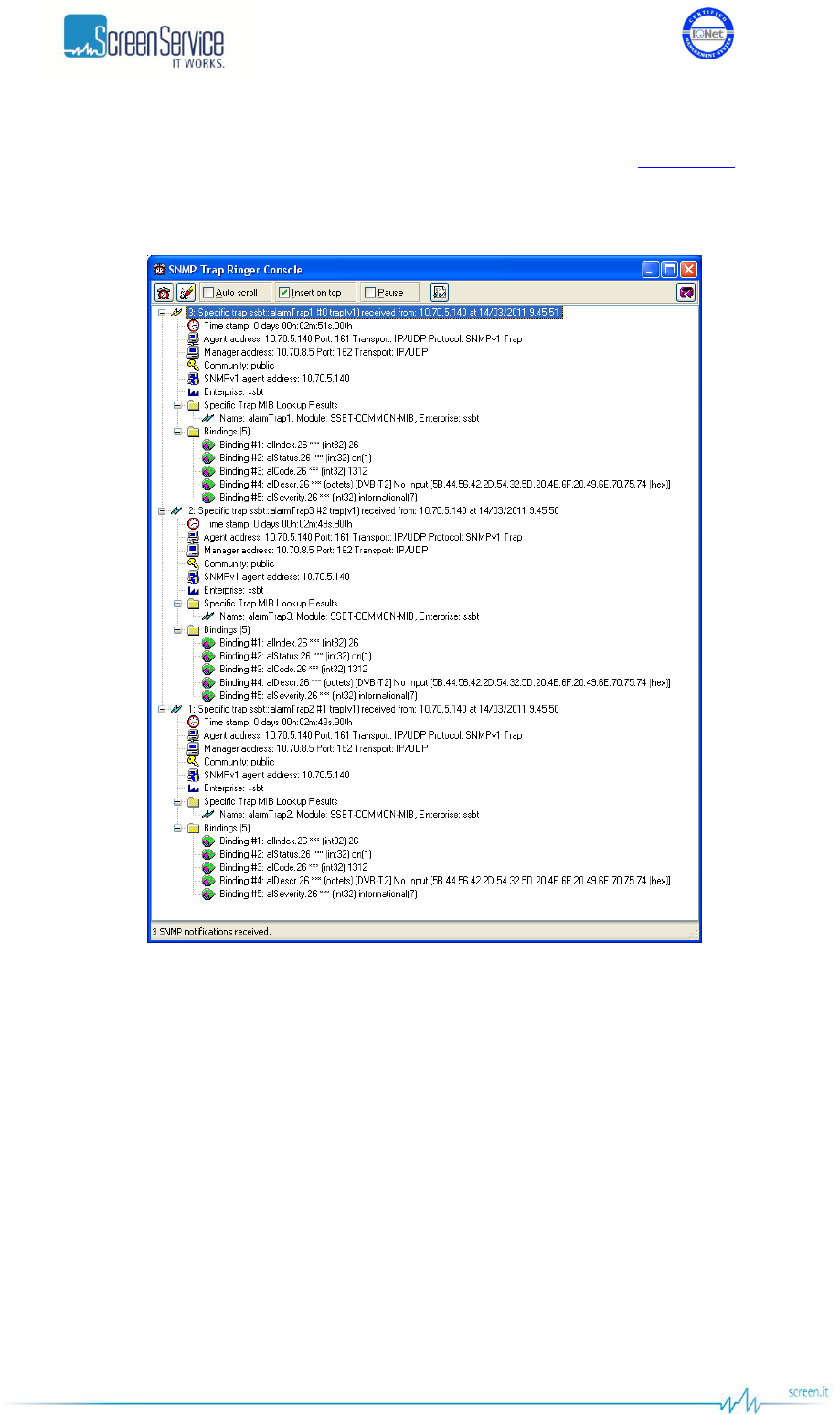
ISO 9001:2000 Cert. N°4500/1
Version 1.1 SDT_ARK6_User_Manual_ENG_vATSC Page 189 of 206
VARIABLES clause defines the ordered sequence of MIB objects, belonging to the specific entry of the alTable,
which are contained within every instance of the trap type. Each variable is placed, in order, inside the variable-
bindings field of the SNMP Trap Message as shown in the following figure (refer to Alarms Table paragraph for
further information about alIndex, alStatus, alCode, alDesc, alSeverity objects).
Figure 58. SNMPv1 Trap Messages

ISO 9001:2000 Cert. N°4500/1
Version 1.1 SDT_ARK6_User_Manual_ENG_vATSC Page 190 of 206
7.5.2 SNMPv2
ARK6 devices transmit alarm-specific traps. For every Trap Manager there is a different SNMv2 trap definition:
traps OBJECT IDENTIFIER ::= { snmp 3 }
alarmTraps1 NOTIFICATION-TYPE
OBJECTS {alIndex, alStatus, alCode, alDescr, alSeverity}
STATUS current
DESCRIPTION
"Traps definition for Trap Manager 1. An alarmTrap1 trap signifies that the sending
protocol entity recognizes that some state transitions occurred in the alarms
table."
::= { traps 1 }
alarmTraps2 NOTIFICATION-TYPE
OBJECTS {alIndex, alStatus, alCode, alDescr, alSeverity}
STATUS current
DESCRIPTION
"Traps definition for Trap Manager 2. An alarmTrap2 trap signifies that the sending
protocol entity recognizes that some state transitions occurred in the alarms
table."
::= { traps 2 }
alarmTraps3 NOTIFICATION-TYPE
OBJECTS {alIndex, alStatus, alCode, alDescr, alSeverity}
STATUS current
DESCRIPTION
"Traps definition for Trap Manager 3. An alarmTrap3 trap signifies that the sending
protocol entity recognizes that some state transitions occurred in the alarms
table."
::= { traps 3 }
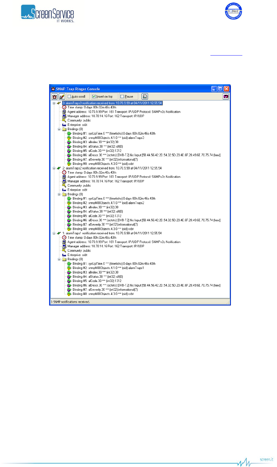
ISO 9001:2000 Cert. N°4500/1
Version 1.1 SDT_ARK6_User_Manual_ENG_vATSC Page 191 of 206
VARIABLES clause defines the ordered sequence of MIB objects, belonging to the specific entry of the alTable,
which are contained within every instance of the trap type. Each variable is placed, in order, inside the variable-
bindings field of the SNMP Trap Message as shown in the following figure (refer to Alarms Table paragraph for
further information about alIndex, alStatus, alCode, alDesc, alSeverity objects).
Figure 59. SNMPv2 Trap Messages

ISO 9001:2000 Cert. N°4500/1
Version 1.1 SDT_ARK6_User_Manual_ENG_vATSC Page 192 of 206
7.5.3 Configuring traps
Use Java (refer to Network and Alarms paragraphs for further information) or SNMP user interfaces to configure
traps.
The configuration of traps is performed through the setting of three different alarm masks, by means of
alTrapManager1, alTrapManager2, alTrapManager3 objects in the alTable (refer to Alarms Table paragraph),
and through the setting of the destination IP Address of the receiving management stations, by means of the
managerTrapTable in the snmp subtree in ssbtCommon MIB.
managerTrapNumber object specifies the total number of entries in the trap manager address table.
Each entry of the managerTrapTable is defined as follows:
ManagerTrapEntry ::= SEQUENCE {
managerTrapIndex INTEGER,
managerTrapIp IpAddress
}
managerTrapIndex is the SNMP manager index.
managerTrapIp object allows the setting of the SNMP manager IP listening address. There are up to 3 different
manager IP addresses that can be configured, one for each alTrapManager mask.
The Community shown in trap messages can be set from Java interface in the Community box within the
Network window (refer to Network paragraph).

ISO 9001:2000 Cert. N°4500/1
Version 1.1 SDT_ARK6_User_Manual_ENG_vATSC Page 193 of 206
Appendix A. Automatic input source selection methods
A.1 Input Autoswitch
The SDT ARK62 series supports an automatic switching control mechanism between incoming signal sources.
The ARK6 is capable of switching between inputs on the basis of primary feed quality, depending on how it is
presented to the transmitter (RF, ASI – Ethernet, SDI and CVBS feeds). The feed switching algorithm is
irrespective of payload and bitrate of both primary and reserve feeds.
The primary input is selected from the drop-down list of Input Selector. It is not allowed to dynamically change
the preferred input until the Input Autoswitch is enabled. Secondary inputs are checked in circular order,
starting from the one that follows the primary input. The numerical order is:
DVB-T - T2 - ISDB-T - ATSC
ITU
1. ASI 1
2. ASI 2
3. ASI 3
4. ASI 4
5. Tuner 1/Tuner (if available)
6. Tuner 2 (if available)
7. GbE 2 ch1
8. GbE 2 ch2
1. SDI 1
2. SDI 2
3. SDI 3
4. SDI 4
5. CVBS 1
6. CVBS 2
E.g. In DVB-T2 mode, if Tuner is set to priority the algorithm for selecting secondary inputs starts with GbE 2
Ethernet channels and then works down all other ASI inputs starting from ASI 1.
If the reserve feed, the one being used, does not meet anymore the necessary quality requirements, the
secondary to secondary input switch mechanism will start from the input that follows the primary input.

ISO 9001:2000 Cert. N°4500/1
Version 1.1 SDT_ARK6_User_Manual_ENG_vATSC Page 194 of 206
Input switching rules can be selected in the Alarms page through the SWITCH alarm mask and depend on the
transmission standard. Here below the available rules for each operative mode:
ITU
[ITU] No Video Input
[ITU] Input wrong standard
ATSC
[ATSC] No Input: input Transport Stream not locked
[ATSC] Input Overflow: input TS overflow
[ATSC] MH Err
[ATSC] FE Demodulator Not Locked: input RF signal not locked
[ATSC] FE SNR Low: RF input SNR under the alarm threshold
[ATSC] No TVCT: TVCT table not present in the selected input stream

ISO 9001:2000 Cert. N°4500/1
Version 1.1 SDT_ARK6_User_Manual_ENG_vATSC Page 195 of 206
Feed selection and switching criteria are available via both transmitter SNMP and Java GUI interfaces.
A Finite State Machine has been used to give a description of the behaviour of the system. The FSM of the Input
Autoswitch algorithm consists of:
Four states:
1. Priority Input Locked
Condition: the primary feed is the one being used.
2. Priority Input Not Locked
Condition 1: the primary feed does not meet the necessary quality requirements as
well as reserve feeds, if any.
Condition 2: the primary feed does not meet the necessary quality requirements and
the FSM is waiting for the primary to secondary feed changeover timeout to elapse.
3. Searching First Locked Input
Condition 1: the primary to secondary feed changeover timeout elapsed and the FSM
is searching for a reserve feed.
Condition 2: the reserve feed, the one being used, does not meet anymore the
necessary quality requirements, the secondary to secondary input switch timeout
elapsed and FSM is searching for another reserve feed.
4. Checking Priority Input
Condition: the reserve input is the one being used and FSM keeps checking the priority
feed to trigger the secondary to primary changeover.
Three countdowns to N seconds, where N is defined by default in the *.def file:
1. Primary to Secondary Switch Counter
It starts when the primary feed does not meet anymore the necessary quality
requirements and the system lay in waiting for the reserve feed to be checked.
2. Secondary to Secondary Switch Counter
It starts when the secondary feed does not meet anymore the necessary quality
requirements and the system lay in waiting for another reserve feed to be checked.
3. Secondary to Primary Switch Counter
It starts when the input set to priority is found to meet again the necessary quality
requirements and the system is waiting to switch back to the primary input.
Timeouts are reset when the actually used input, whether it is the preferred one or not, regain his quality
requirements.

ISO 9001:2000 Cert. N°4500/1
Version 1.1 SDT_ARK6_User_Manual_ENG_vATSC Page 196 of 206
A.2 Seamless input switching
SDT ARK6 series supports a seamless input switching algorithm that increases the reliability of the system in a
SFN environment. The developed algorithm is capable of changing input signal source on the basis of MIP
packets within the incoming Transport Stream. The algorithm provides a reserve feed to the apparatus in a SFN
environment in the event that the primary input signal source does not meet anymore the SFN constrains. The
device is designed to manage the redundancy between two different sources in a SFN environment by seamless
switching between them
Both HP and LP streams have two different selected inputs. The two selected input are real-time analyzed under
some presence and validity rules. The inputs that are present and valid are eligible to be sent to output in
dependence on the priority rule set. If only one input is present, then is sent to output without the application of
any validity rule.
The presence of an input is evaluated under the following rules:
The input is an ASI compliant (CEI EN 80083-9) encoded signal.
The input transports an MPEG-2 TS (ITU.T 13818-1) with no Synchronization Error (as defined by ETSI
ETR 290).
The validity of an input is evaluated under the following rules:
The Transport Error flag (as defined by ITU.T 13818-1) does not rise in any packet.
The timing of reception of each input packet is inside the standard boundaries (as defined by ETSI ETR
290).
The SFN adaptation of the input TS is guaranteed by the presence of a correct MIP (as defined by ETSI
TR 101 191), guaranteed by a CRC32 algorithm checking.
The TS data validity is guaranteed by the presence of PAT (as defined by ETSI EN 300 468) correct after a
CRC32 algorithm checking.
The TS data validity is guaranteed by the presence of PMT (as defined by ETSI EN 300 468) correct after
a CRC32 algorithm checking.
The total delay applied by the distribution network to the input signal is not higher than the Max Delay
set by the SFN adapter.
The time window available to deliver the TS to the output is higher than the network margin applied.
When the used input check fails, the device seamlessly switches to the secondary input if present and valid,
otherwise it continue to output the same flow despite of the validity rules check.

ISO 9001:2000 Cert. N°4500/1
Version 1.1 SDT_ARK6_User_Manual_ENG_vATSC Page 197 of 206
Appendix B. Java Virtual Machine
The Java interface requires a host computer connected via Ethernet to the board with the proper Java Machine
version installed.
B.1 Ethernet connection
The host computer has to be connected via Ethernet to the board.
Direct or crossed UTP category 6 cable is recommended.
NOTE: for best performances, a fast connection (i.e. gigabit Ethernet) is required. After careful testing it was
found that a slow connection makes it difficult the use of precorrection tools.
B.1.1 Configuration
In order to connect to the board trough a LAN, all the devices have to be on the same network.
The default IP address settings of the X-port are:
IP address: 10.77.xx.xx , where xx is the host address unique for each board.
Subnet mask: 255.255.0.0.
Remember to change these settings if they are not compatible with the LAN where the computer and the board
are connected.
IP address and network parameters can be changed only using the local interface. Please refer to chapter 6 for
the network setting commands.
B.2 Java(TM) Platform
B.2.1 Download
The Java Interface works with any Sun Java Virtual Machine after the 1.4.1 version.
If the computer has no Java Virtual Machine installed, the recommended 1.5.0 version can be downloaded from
the Sun Server trough this link:
http://www.java.com/
B.2.2 Java Control Panel
Java caching must be disabled.
B.3 Supported Web Browsers
The Java GUI is designed to support every Web Browser that uses Sun Java Virtual Machine from 1.4.1 and
newer.
Here’s a list of Web Browsers where Java GUI has been tested and troubleshot: Microsoft Internet Explorer,
version 5 and newer. Mozilla Firefox, version 1.5 and newer.
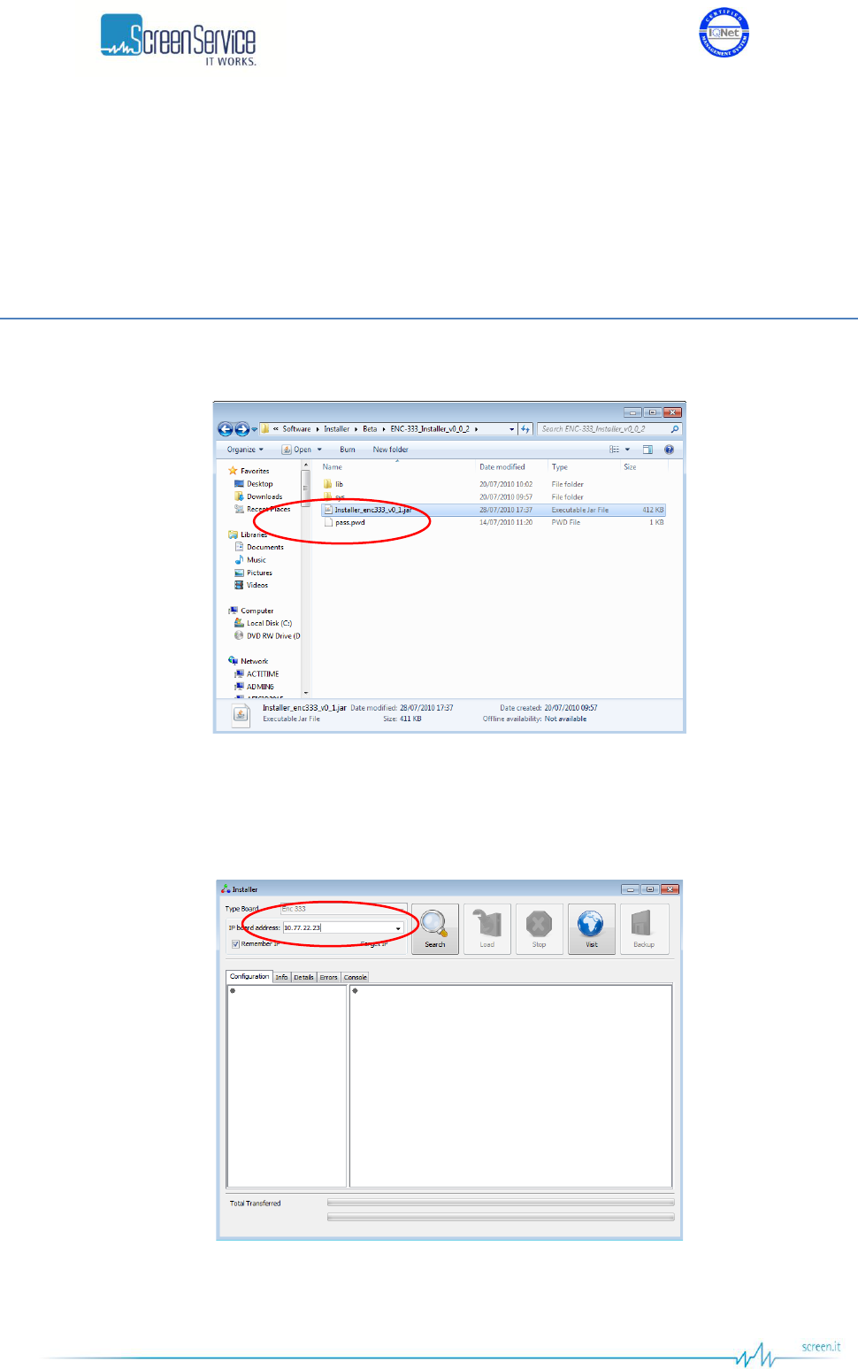
ISO 9001:2000 Cert. N°4500/1
Version 1.1 SDT_ARK6_User_Manual_ENG_vATSC Page 198 of 206
Appendix C. Application Note
Screenshots of this application note are used as an example and the shown file names are not related to ARK6-
T2 device.
C.1 How to update
1. Launch the Java installer.
Figure 60. Java installer
2. Insert the IRRM2 BTS Remux IP address into the numeric field.
Figure 61. Java installer – IP address insertion
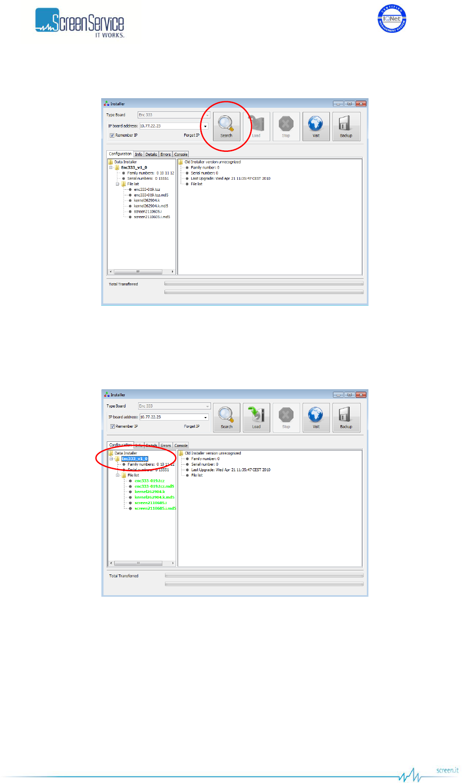
ISO 9001:2000 Cert. N°4500/1
Version 1.1 SDT_ARK6_User_Manual_ENG_vATSC Page 199 of 206
3. Click the Search button.
Figure 62. Java Installer – Search button
4. Select the device version you want to load.
Figure 63. Java Installer - Device selection
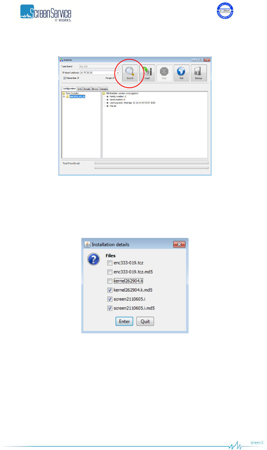
ISO 9001:2000 Cert. N°4500/1
Version 1.1 SDT_ARK6_User_Manual_ENG_vATSC Page 200 of 206
5. Click on the “Load” button.
Figure 64. Java Installer – Load button
6. If you want to update only some software versions, click on the check boxes corresponding to the
software version you want to load, otherwise click on the check box corresponding to the Load All
option. Click on the “Enter” button to start the loading.
Figure 65. Java Installer – Software versions selection
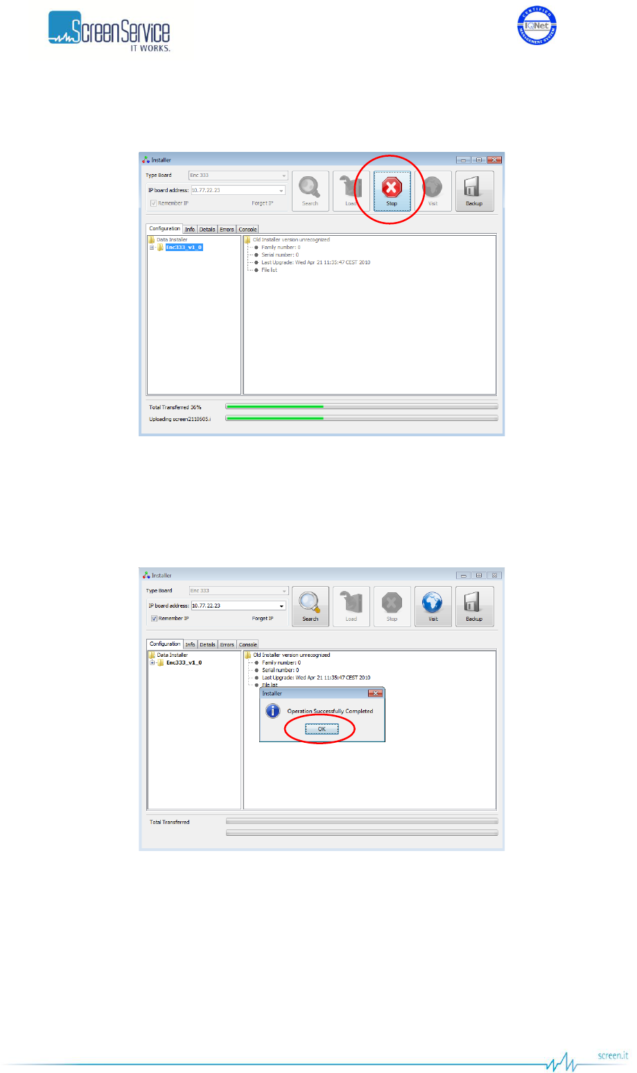
ISO 9001:2000 Cert. N°4500/1
Version 1.1 SDT_ARK6_User_Manual_ENG_vATSC Page 201 of 206
7. Once started the loading, the “Stop” button lights up. Click on this button to interrupt the
programming.
Figure 66. Java Installer – Stop button
8. When the loading is complete, the pop-up window “Operation Successfully Completed” appears. Click
on the “OK” button.
Figure 67. Java Installer – Operation Successfully Completed
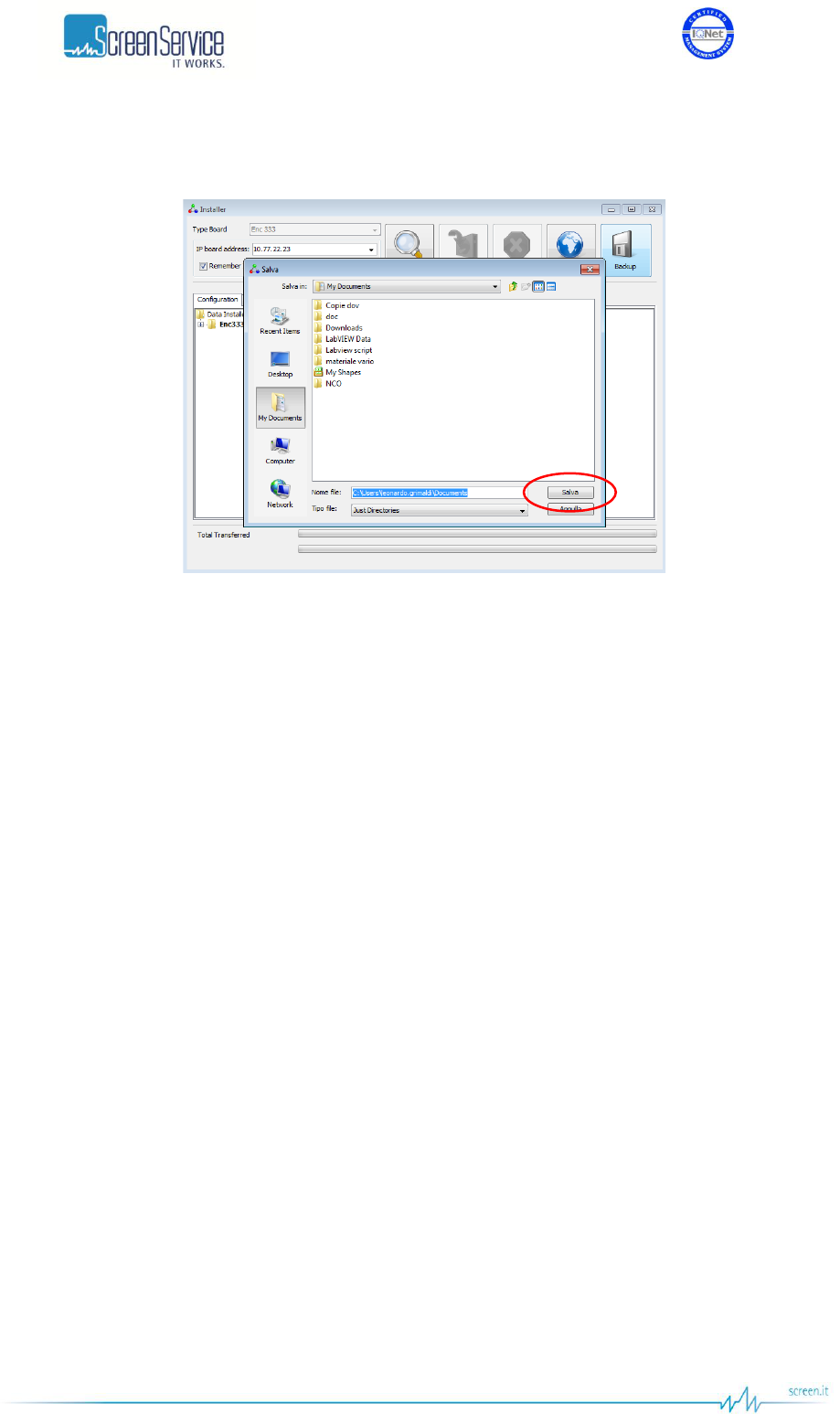
ISO 9001:2000 Cert. N°4500/1
Version 1.1 SDT_ARK6_User_Manual_ENG_vATSC Page 202 of 206
9. To save a copy of the file system click on “Backup” button. A pop-up window “Salva” appears. Specify
the saving path, then click on “Salva” button.
Figure 68. Java Installer – Backup Save button

ISO 9001:2000 Cert. N°4500/1
Version 1.1 SDT_ARK6_User_Manual_ENG_vATSC Page 203 of 206
Appendix D. Document versions
Table 33. Document Versions
Version
Author
Revised by
Date
Note
1.0
Di Biase
November 8th, 2011
First version with all the
operative modes.
1.1
Di Biase
November 23rd, 2011
Updated paragraphs 4.2 and
4.4.

ISO 9001:2000 Cert. N°4500/1
Version 1.1 SDT_ARK6_User_Manual_ENG_vATSC Page 204 of 206
List of Tables
Table 1. Hardware options .................................................................................................................... 8
Table 2. RS232 DE-9 pinout ................................................................................................................. 23
Table 3. TLC pinout .............................................................................................................................. 23
Table 4. TLS pinout .............................................................................................................................. 24
Table 5. Input window ........................................................................................................................ 33
Table 6. Tuner window: RF power level monitor ................................................................................ 38
Table 7. CVBS Inputs: Statistics ........................................................................................................... 40
Table 8. ATSC RF Input: Status and demodulation parameters .......................................................... 42
Table 9. ATSC Processing: ATSC Settings ............................................................................................. 46
Table 10. ATSC Processing: ATSC Modulation....................................................................................... 50
Table 11. ATSC Measure: RF power level monitor ................................................................................ 53
Table 12. ITU Processing: ITU Settings .................................................................................................. 56
Table 13. ITU Modulation: Modulator manager ................................................................................... 61
Table 14. ITU Modulation: Modulator test modes ............................................................................... 64
Table 15. Adaptive Linear Precorrection: Management panel ............................................................. 72
Table 16. Adaptive Non Linear Precorrection: Management panel ..................................................... 75
Table 17. Output window...................................................................................................................... 77
Table 18. Output window: Reflex Pwr Management ............................................................................ 86
Table 19. Network window ................................................................................................................... 88
Table 20. GPS window ........................................................................................................................... 93
Table 21. GPS window: Holdover Management ................................................................................... 96
Table 22. Alarms window .................................................................................................................... 100
Table 23. Events descriptions list ........................................................................................................ 117
Table 24. Alarms descriptions list ....................................................................................................... 121
Table 25. Task error event specific data ............................................................................................. 126
Table 26. Init system event specific data ............................................................................................ 128
Table 27. Local User Interface: Idle Menu .......................................................................................... 140
Table 28. Local User Interface: submenus descriptions ..................................................................... 141
Table 29. Alarms descriptions list ....................................................................................................... 142
Table 30. ARK6 SNMP Tree Structure ................................................................................................. 148
Table 31. Alarms Code and Description .............................................................................................. 183
Table 32. Alarm Thresholds Description ............................................................................................. 186
Table 33. Document Versions ............................................................................................................. 203

ISO 9001:2000 Cert. N°4500/1
Version 1.1 SDT_ARK6_User_Manual_ENG_vATSC Page 205 of 206
List of Figures
Figure 1. DE-9 Male connector ............................................................................................................. 23
Figure 2. TLC connector ........................................................................................................................ 23
Figure 3. TLS connector ........................................................................................................................ 24
Figure 4. GUI - Login ............................................................................................................................. 28
Figure 5. Java menu bar ....................................................................................................................... 29
Figure 6. System commands bar .......................................................................................................... 29
Figure 7. Operation pages bar .............................................................................................................. 30
Figure 8. System menu ......................................................................................................................... 30
Figure 9. Home Page window ............................................................................................................... 31
Figure 10. ATSC / DVB-T/T2 Input window ............................................................................................ 32
Figure 11. Front-End window ................................................................................................................. 37
Figure 12. Tuner window: RF power level monitor ................................................................................ 38
Figure 13. CVBS Inputs: Statistics ........................................................................................................... 39
Figure 14. ATSC RF Input: Status and demodulation parameters .......................................................... 41
Figure 15. ATSC window ......................................................................................................................... 44
Figure 16. ATSC Processing: ATSC Settings ............................................................................................. 45
Figure 17. ATSC Processing: ATSC Modulation....................................................................................... 49
Figure 18. ATSC Processing: ATSC Modulation....................................................................................... 51
Figure 19. ATSC TVCT: Add button ......................................................................................................... 51
Figure 20. ATSC Processing: ATSC Measure ........................................................................................... 52
Figure 21. ATSC Measure: RF power level monitor ................................................................................ 53
Figure 22. ITU window ............................................................................................................................ 54
Figure 23. ITU Processing: ITU Settings .................................................................................................. 55
Figure 24. ITU Processing page: ITU Modulation ................................................................................... 59
Figure 25. ITU Modulation: Modulator manager ................................................................................... 60
Figure 26. ITU Modulation: Modulator test modes ............................................................................... 63
Figure 27. Adaptive Linear Precorrection ............................................................................................... 66
Figure 28. AM/PM Precorrection ........................................................................................................... 68
Figure 29. Realizing connection .............................................................................................................. 69
Figure 30. Adaptive Linear Precorrection ............................................................................................... 70
Figure 31. Adaptive Filter ....................................................................................................................... 71
Figure 32. Filter window: complex filter coefficients graph ................................................................... 73
Figure 33. Filter window: module graph ................................................................................................ 73
Figure 34. Filter window: phase graph ................................................................................................... 73

ISO 9001:2000 Cert. N°4500/1
Version 1.1 SDT_ARK6_User_Manual_ENG_vATSC Page 206 of 206
Figure 35. Adaptive Non Linear Precorrection ....................................................................................... 74
Figure 36. Output window...................................................................................................................... 76
Figure 37. Reflex Pwr Management ....................................................................................................... 85
Figure 38. Network window ................................................................................................................... 87
Figure 39. GPS window ........................................................................................................................... 92
Figure 40. Holdover Management ......................................................................................................... 94
Figure 41. Alarms window ...................................................................................................................... 99
Figure 42. Events window .................................................................................................................... 116
Figure 43. Time and date setting .......................................................................................................... 126
Figure 44. Menu bar ............................................................................................................................. 131
Figure 45. File menu ............................................................................................................................. 131
Figure 46. View menu ........................................................................................................................... 132
Figure 47. Time window ....................................................................................................................... 133
Figure 48. Alerts window ...................................................................................................................... 133
Figure 49. Alert message ...................................................................................................................... 134
Figure 50. Help menu ........................................................................................................................... 135
Figure 51. About window ..................................................................................................................... 135
Figure 52. Info window: Serial Numbers .............................................................................................. 136
Figure 53. Info window: Server File System Content ........................................................................... 136
Figure 54. Info window: Client System Parameters ............................................................................. 136
Figure 55. Download Software Standalone .......................................................................................... 137
Figure 56. SNMP Protocol Preferences ................................................................................................ 145
Figure 57. ARK6 Tree Structure ............................................................................................................ 146
Figure 58. SNMPv1 Trap Messages ...................................................................................................... 189
Figure 59. SNMPv2 Trap Messages ...................................................................................................... 191
Figure 60. Java installer ........................................................................................................................ 198
Figure 61. Java installer – IP address insertion .................................................................................... 198
Figure 62. Java Installer – Search button ............................................................................................. 199
Figure 63. Java Installer - Device selection ........................................................................................... 199
Figure 64. Java Installer – Load button ................................................................................................ 200
Figure 65. Java Installer – Software versions selection ........................................................................ 200
Figure 66. Java Installer – Stop button ................................................................................................. 201
Figure 67. Java Installer – Operation Successfully Completed ............................................................. 201
Figure 68. Java Installer – Backup Save button .................................................................................... 202