Se Jin Electron SKR-2006 Keyboard User Manual THE SPECIFICATION
Se Jin Electron Inc Keyboard THE SPECIFICATION
users manual
1
User’s Manual
(SKR-2006)
Sejin Electron Inc.

2
FCC NOTICE
THIS DEVICE COMPLIES WITH PART 15 OF THE FCC FULES.
OPERATION IS SUBJECT TO THE FOLLOWING TWO CONDITION:
(1) THIS DEVICE MAY NOT CAUSE HARMFUL INTERFERENCE, AND
(2) THIS DEVICE MUST ACCEPT ANY INTERFERENCE RECEIVED,
INCLUDING INTERFERENCE THAT MAY CAUSE UNDERSIRED
OPERATION.
This equipment has been tested and found to comply with the limits for a Class B digital device,
pursuant to part 15 of the FCC Rules. These limits are designed to provide reasonable protection
against harmful interference in a residential installation. This equipment generates, uses and can
radiate radio frequency energy and, if not installed and used in accordance with the instructions,
may cause harmful interference to radio communication. However, there is no guarantee that
interference will not
occur in a particular installation. If this equipment does cause harmful interference to
radio or television reception, which can be determined by turning the equipment off and on, the
user is encouraged to try to correct the interference by one or more of the following measures :
- Reorient or relocate the receiving antenna.
- Increase the separation between the equipment and receiver.
- Connect the equipment into an outlet on a circuit difference from that to which
the receiver is connected.
- Consult the dealer of an experienced radio/TV technician for help.
NOTE : The manufacturer is not responsible for any radio or TV interference caused by
unauthorized modifications to this equipment. Such modifications could void the user’s
authority to operate the equipment.
3
1.0 ELECTRRICAL
1.1 Power
1.1.1 5VDC±10%, 40mA .
2.0 POWER ON ROUTINE
2.1 Power on Reset-POR-
2.2.1 The keyboard will perform a power on reset -POR- within a minimum of
150㎳ and a maximum of 2 ㎳.
2.2 Basic Assurance Test -BAT-
2.2.1 The keyboard will conduct a basic assurance test -BAT- of the processor.
2.2.2 Turn the LED's(if so equipped) on at the beginning of the test and off at
the end of the test.
2.2.3 Transmit the completion code AAH if the test was successful.
2.2.4 The -BAT- takes a maximum of 500 ㎳. During this time all activity on the
clock and data lines will be ignored.
2.2.5 The completion code will be transmitted within 450 ㎳ and not more than
2.5sec after -POR-, and within 500 ㎳ after a reset command is acknowledge.
3.0 DATA TRANSMISSION
3.1 Clock and Data lines
3.1.1 The click and data lines are used for communication in both directions
between the system and the keyboard. These lines are driven by an open
collector device which allows either the system or the keyboard to force the
line to an inactive(low)level. When no communication is occurring both lines
are active(high).
3.1.2 The keyboard provides the clocking signals used to clock serial data to and
from the keyboard.
3.1.3 The data line is used for transmission of data by both the system and the
keyboard. The system issues a`Request to Send' -RTS- by pulling the data line
to logic`0'.
3.2 DATA format
3.2.1 The data protocol is an 11-bit data stream that consists of 1 start
bit(always Logic 0), 8 data bits(least significant bit to most significant bit
respectively), 1 odd parity bit, and 1 stop bit(always Logic 1).
3.2.2 See figure 14 for graphic representation of these signals.
3.3 Keyboard to System line protocol
3.3.1 Keyboard checks clock line, if Logic 1 continue, if Logic 0 store keystrokes
if protocol is 11-bit(inhibited); otherwise check for possible reset.
3.3.2 Keyboard checks data line, if Logic 1 continue, if Logic 0 prepare to receive
data from system if protocol is 11-bit; otherwise store keystrokes(inhibited).
3.3.3 Keyboard transmits data. While transmitting in the 11-bit protocol, the
keyboard checks the clock line for logic level 1 at least every 60 ㎲.(See line
contention below).
3.4 Line Contention
3.4.1 The system may interrupt keyboard data transmission at any time up to the
10th clock by pulling the system must receive the keyboard data.
3.5 Line Contention
3.5.1 System inhibits keyboard by lowering clock line to logic 0 for a minimum of
60㎲.
3.5.2 System requests transmission by lowering the data to logic 0(-RTS-)and
allows the clock line to go active.
4
3.5.3 Keyboard monitors the clock line(10 ㎳ intervals)and detects the active level.
3.5.4 Keyboard detects -RTS-on the data line and clocks it in as the logic 0 start
bit. then clocks 8 data bits and parity.
3.5.5 Keyboard looks for a logic 1 on the data line then forces it low clocks one
more bit. This action signals the system that the keyboard has received the
data. If the data line is not at logic level 0 following the 10th bit, the
keyboard will continue to clock bits until the line becomes active. The
keyboard then pulls data line low and transmits a resends.
4.0 FIFO
4.1 FIFO Capacity
4.1.1. The keyboard contains at least a 16-byte first-in-first-out(FIFO)buffer. The
keyboard stores the scan codes until the system is ready to receive them.
4.2 Overrun Conditions
4.2.1 A buffer-overrun condition occurs when the keyboard tries to place more
characters than the keyboard buffer can hold. When this occurs, an overrun
code(FFH for scan code set 1, and 00H for scan code sets 2&3)replaces the
last byte. If more keys are pressed before the system allows keyboard
output, the additional data lost.
4.3 Special Cases
4.3.1 When the keyboard is allowed send data, the bytes in the buffer will be sent
as in normal operation, and new data entered is detected and sent. Response
codes do not occupy a buffer position.
4.3.2 If keystrokes generate a multiple-byte sequence, the entire sequence must fit
into the available buffer space or the keystroke is discarded and a buffer
overrun condition occurs.
5.0 KETS
5.1 Key Type Description
5.1.1 While using scan code sets 1&2, all the keys on the keyboard are
make/break (M/B) except station 16. Scan code set 3 default conditions are
given in the code tables. The make scan code is sent to the system when
the key is depressed and the break code is sent when the key is released.
5.2 Auto-Repeat Protocol
5.2.1 If a key is typmatic (auto-repeats), the key will auto-repeat after the initial
delay has expired. Rollover to another auto-repeat key will stop repeating
operation and will produce the scan code for the second key. After an initial
delay, the keyboard will the second code.
6.0 PC CABLE CONNECTOR
6.1 Pinout Table
6pin 5pin
DIN Signal Type
5 1 KBD Clk I/O
1 2 KBD data I/O
2 3
3 4 Ground Power
4 5 +5.0Vdc Power
5
Shield Shield Fram GND
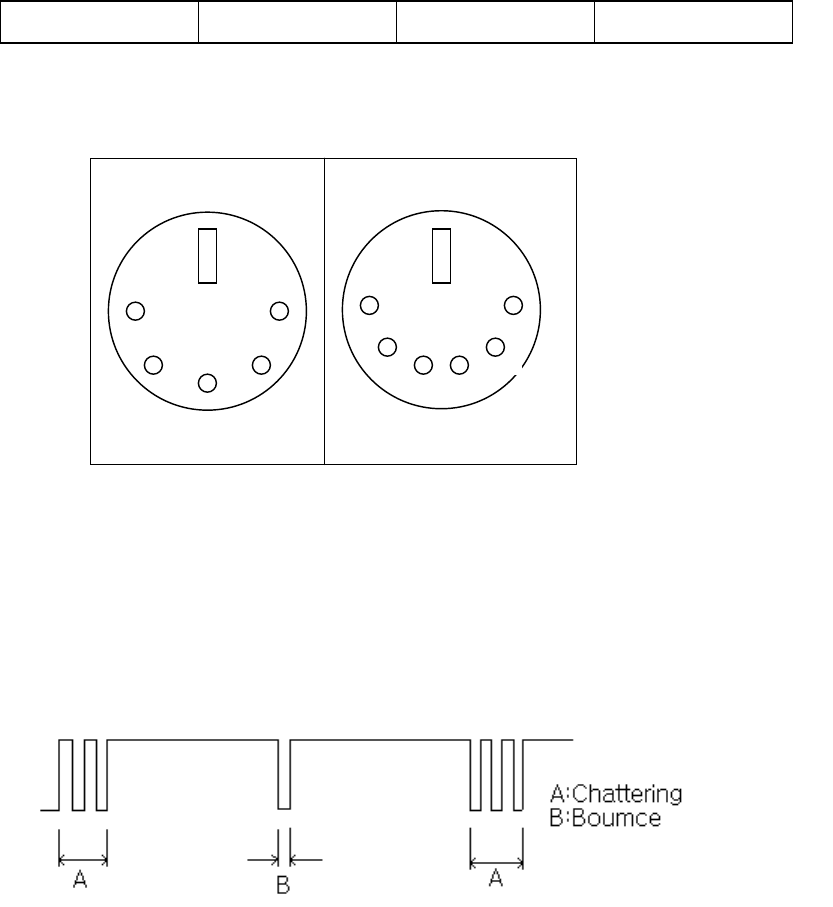
6.2 Connector Schematics
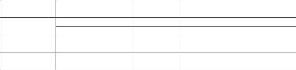
7.0 CHATTERING AND BOUNCE
Operation force shall be applied according to the normal operating method at 5V DC,
5mA.There shall be no bounce and chattering within 10msec when it is measured using a
specially prepared tester or a synchroscope.
※ Chattering and bounce are defined in the following diagram :
8.0 TEMPERATURE AND HUMIDITY
12.0.1 Based on laboratory test conditions, there shall be no electrical or
mechanical damage to the keyboard as a result of the following tests.
12.1 Operating
12.1.1 The keyboard will be capable of withstanding 10 to 40 degrees C with a 40
degree C maximum wet bulb temperature (20% to 95%max. relative humidity
non condensing) cycled for 10 days.
12.2 Storage
12.2.1 The keyboard will be capable of withstanding a temperature of -20 degrees
C to +60 degrees C with a 48 degree C maximum wet bulb temperature(90%
max. humidity non condensing)cycled for ten days.
9.0 DROP TEST(NON-OPERATION)
Purpose of test: To verify the keyboard’s ability to withstand being dropped from lap and desk
heights.
Test Parameters/Conditions: 25°C @ 50% R.H.
Standard: After test, If the keyboard is recoverable(able to be re- assembled), it is
2
2
1
1
3
3
4
4
5
5 6
5 PIN DIN 6 PIN
6
acceptable.
Packing
Condition Drop surface Height Test Description
Hard wood 70Cm 2 drops for each corner
Non-packing Carpet 70Cm 1drop for 6 surfaces
Inner box Concrete 90Cm 1drop for 6 surfaces and 4 corners.
(Totally 10drop)
Out box Concrete 60Cm 1drop for 6 surfaces and 4 corners.
(Totally 10drop)
10.0 VIBRATION
10.1 Pack non operate
14.1.1 The keyboards as packaged in individual boxes (exclusive of bulk pack or
overpack containers) shall withstand 24 hours of vibration of 50 Hz and 5
G`s without electrical or mechanical damage to the keyboard. The shipping
container will be rigidly mounted with the key array in the up position.
10.2 Unpacked operated
14.2.1 The keyboard in its normal operation, shall withstand 24 hours of cycling
between 10 and 59 Hz at 0.005inch displacement double amplitude.
10.3 Unpacked, Non operate
14.3.1 The keyboard in its normal operating position shall withstand 30 minutes of
cycling 56 Hz to 500 Hz at 2.0G`s in each of its three major axis.
11.0 ELECTROSTATICS DISCHARGE(ESD)
11.1 Test Method
15.1.1 Test per IEC 801-2
15.1.2 Direct Discharge applied to all areas which may be touched by an operator
with the keyboard in it`s normal operating position.
11.2 Field Limits
11.2.1 E-Field 0 to ±12KV
11.2.2 H-Field 0 to ±12KV
11.2.3 Direct Discharge 0 to 12 KV
11.3 Keyboard Operation
15.3.1 The keyboard shall be tested such that keyboard output can be monitored
during test using a word processing program.
11.4 Error Definition
11.4.1 Soft Error-Temporary loss of function during test, however function can be
restored without initiating a reset command, or cycling of the power.
11.4.2 Hard Error-The keyboard becomes locked up or hangs and operation
continues only after a reset command or power to the keyboard is cycled.
11.4.3 Hardware Error-The keyboard has sustained damage such that continued
operation cannot occur.
11.5 Performance Criteria
11.5.1 ±6KV No error Allowed
11.5.2 ±8KV Soft Errors Allowed
11.5.3 ±10KV Hard Error Allowed
11.5.4 ±12KV No Hardware Errors are permitted.
7
12.0 ALTITUDE
16.1 Operating and Storage
The keyboard shall withstand both an operating and storage altitude of sea
level to 15,000 feet.
13.0 KEY LIFE TEST
Standard: a. key-switch life: 10,000,000 cycles
b. Test equipment : Plunger Type.
Actuation speed : 4 times/sec
Press pressure : 200±50gf
14.0 AGENCY APPROVALS
18.0.1 SEJIN ELECTRON keyboards are UL recognized (UL file XXXXXXX)
and CSA certified (CSA file #XXXXXXXX) components. Any proposed changes,
to the generic keyboard design, must be reviewed by SEJIN ELECTRON
Engineering to determine any impact on agency approvals prior to incorporation
of said change into production keyboards.
15.0GENERAL KEYBOARD REQUIREMENTS
15.1Membrane.
Contact membrane switching technology is applied. The membrane
consists of a two layers of EL grade polyester printed with a combination of
silver/carbon and UV dielectric compounds.
15.2 Contact resistance
20.2.1 Closed circuit resistance 300Ω(max)
20.2.2 Open circuit resistance 100 ㏁(min)
15.4 Insulation Resistance
19.4.1 (measured between any two adjacent sense or drive line) 100 ㏁minimum,
with 100 VDC test voltage.
15.5 Key top Height Variation
The key top height variation must not greater than 0.5mm when measured between the center to
center of keys next to each other. The measurement will be performed with keys in the home
positions.
15.6 Keytop Alignment
The key top alignment tolerances must not exceed 0.5mm when keytop measured between the
center to center of keys next to each other. The measurement will be performed with keys in the
home positions.
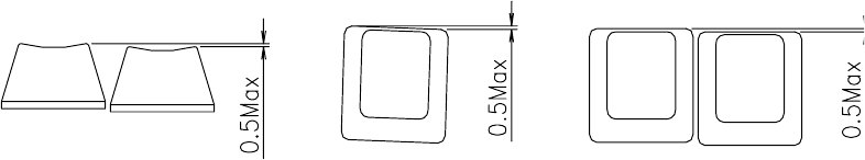
15.7 Rotational Alignment
The maximum rotation of key shall be less than 0.5mm as shown below.
Rotational Alignment Alignment
Height variation
15.8 End stroke strength
End stroke should withstand a static load of 500gf applied on the tip of the key stem in the
perpendicular direction for 1minute.
8
15.9 Keytop pulling strength
The keytop pull out force shall be 0.5Kg or more at normal temperature during initial conditions.
The keytop shall be not pulled out by an ordinary typing operations.
9