Se Jin Electron SKR-4200SU KEYBOARD User Manual skr 4200SU CE FCC
Se Jin Electron Inc KEYBOARD skr 4200SU CE FCC
USERS MANUAL
SEJIN ELECTRON, INC
1 SCOPE
This document provides a specification for the SEJIN AND OEM USB keyboard.
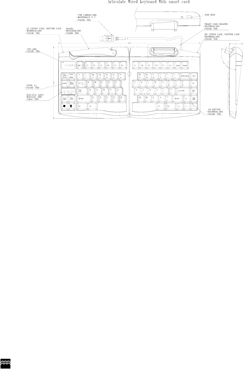
2 THE SEJIN Mini-keyboard with FSR MOUSE,SMART CARD
z Designed with the users in mind, it has a pleasant appearance and is
Convenient to use.
z No extra power supply is required.
z It is compatible with the Microsoft Keyboard and Trackball, Smart card
z
3 Mini-keyboard with FSR MOUSE INSTALLATION
z Turn the power supply off to your computer.
z Check the USB port at the back of your computer and insert
The connrctor at the end of the Mini key-board cables into the USB port
z Turn the power supply on to your computer.
4 MECHANICAL PERFORMANCE
4.1 Key switch Operation
2.1.1 Operating system
Non - lock rubber tactile feeling.
2.1.2 Stroke
3.5±0.5mm with measuring load 200gf applied.
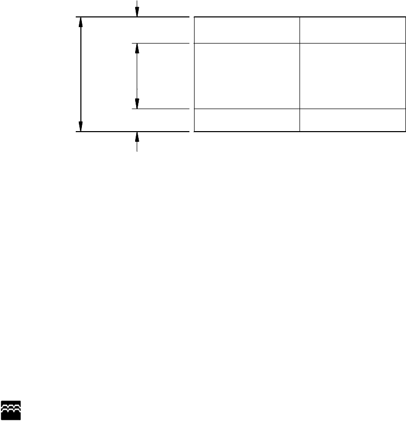
2.1.3 Operating Region
ON/OFF
Swithing
region
0.7mm
0.8mm
Total traval
3.5±0.5mm
Bottom en
d
To
p
en
d
ON re
g
ion
OFF re
g
ion
Need to modify the above diagram according to new key travel.
2.1.4 Operating force
The operating curve is defined to the following drawing and the relationship
between the operating force and travel is provided. The operating force has a
tolerance of 60±25gf
4.2 Operating feeling
No definite stickiness or other abnormality shall be allowed when force is applied with a
finger to key-top center at the rate of 3 times on a second.
4.3 Using the Keyboard
SEJIN ELECTRON, INC
you can have access to all the key functions of a full-sized keyboard
Using the Numeric Keypad
Press NumLK key to turn on the embedded numeric key pad. The numeric functions of the key pad are
Enabled and the NumLock LED turn on.
To turn the numeric key pad off, press NumLK again The Num Lock LED turn off.
5 WORKMANSHIP STANDARDS
5.1 Electrical Criteria
Electrical assemblies and components shall meet the requirements of commercial.
5.2 Keycap Cosmetics
The legend of keycap has to be printed with LASER cutting methodology by SEJIN standard and will
have to pass the Sejin standard abrasion test.
6 ELECTRICAL REQUIREMENTS
6.1 Operating voltage range
DC 4.0V ~5.25V
6.2 Operating current
Max 250mA, 5VDC
6.3 Insulation resistance
More than 100M ohm at 250V DC
6.4 Contact resistance
2KΩor less
SEJIN ELECTRON, INC
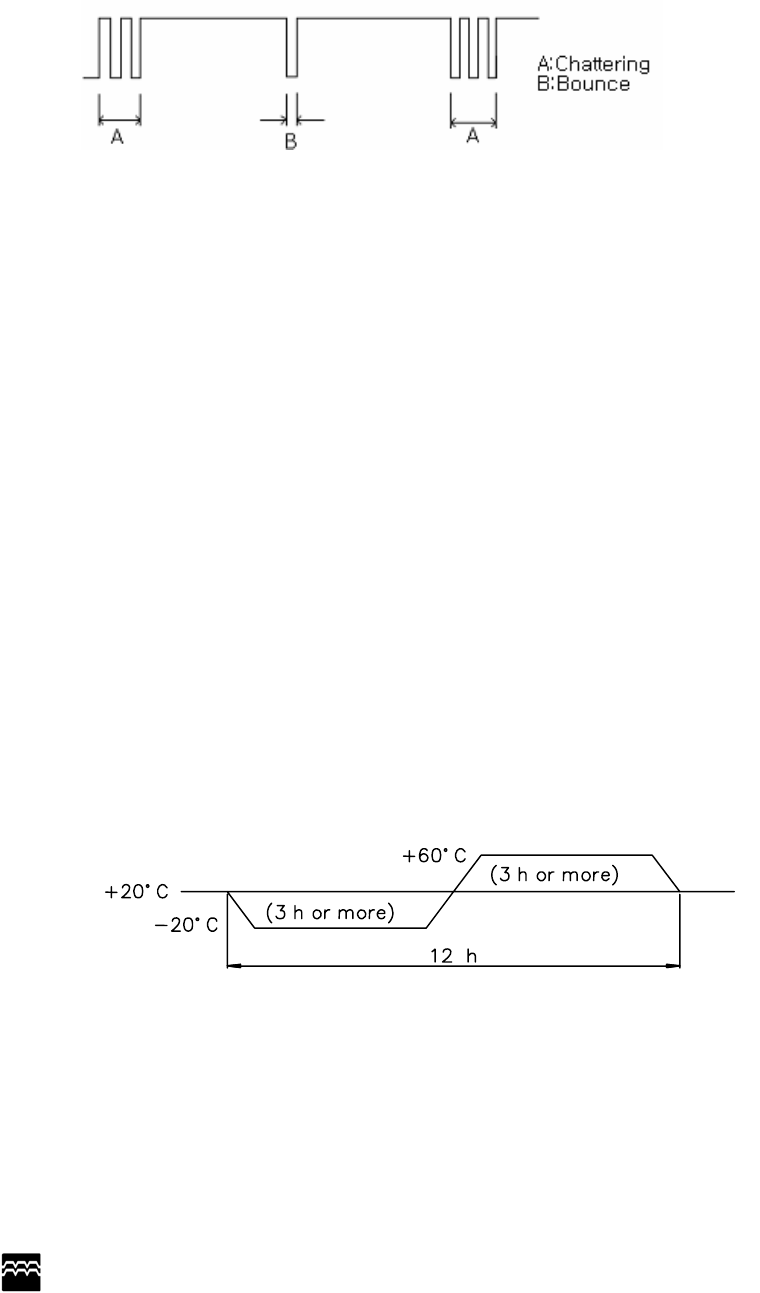
6.5 Chattering and bounce
The operation force shall be applied according to the normal operating method at 5V DC, 5mA.There shall
be no bounce and chattering within 10msec when it is measured using a specially prepared tester or a
synchroscope.
Chattering and bounce are defined as following diagram :※
7 ENVIRONMENTAL REQUIREMENTS
The following specifications pertain to the keyboard assembly.
7.1 Operational ambient temperature and humidity
Temperature : 0 ~ 50℃
Humidity : 85%RH
7.2 Storage ambient temperature and humidity
Temperature : -20 ~ 60℃
Humidity : 95%RH
7.3 Shock
There should be no abnormal operation and appearance of the keyboard when an impact of 10G has
been applied to the packaged keyboard. The testing method shall be in accordance with 213B of MIL-
STD-202E
7.4 Key life Test
Standard: a. key-switch life: 10,000,000 cycles of operation at 25 degrees Celsius ambient temperature. The
cycling rate is between 10 to 1000 cycles of operation per minute
1) Test equipment : Plunger Type.
2) Actuation speed : 4 times/sec
3) Press pressure : 150±50g
7.5 Heat Cycle Test
Check Method: By the condition shown in the figure below, repeat heat cycle
test for 2 times.
Standard: When the test is finished, followings must be satisfied.
a. All functions operate normally.
b. There are no defects which harm commercial value, e.g., change
of color, rust or change of form.
7.6 Low Temperature Test
Check Method: Leave for 96 hours under –25℃.
SEJIN ELECTRON, INC
Standard: The keyboard operates normally after the test.
7.7 High Temperature Test
Check Method: Leave for 96hours under +70℃.
Standard: The keyboard operates normally after the test.
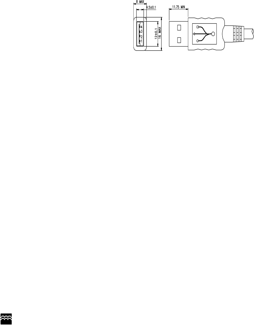
8 USB Keyboard interface
The keyboard comprises the key switch section and signal processing circuit.
The keyboard cable connects to the system with a USB connector.
The following table shows the pin configuration and signal assignments.
Contact Number Signal Name
1 VBUS
2 D-
3 D+
4 GND
Shell Shield
FCC NOTICE
THIS DEVICE COMPLIES WITH PART 15 OF THE FCC RULES.
OPERATION IS SUBJECT TO THE FOLLOWING TWO CONDITION:
(1) THIS DEVICE MAY NOT CAUSE HARMFUL INTERFERENCE, AND
(2) THIS DEVICE MUST ACCEPT ANY INTERFERENCE RECEIVED,
INCLUDING INTERFERENCE THAT MAY CAUSE UNDERSIRED
OPERATION.
This equipment has been tested and found to comply with the limits for a Class B
digital device, pursuant to part 15 of the FCC Rules. These limits are designed to
provide reasonable protection against harmful interference in a residential installation.
This equipment generates, uses and can radiate radio frequency energy and, if not
installed and used in accordance with the instructions, may cause harmful interference
to radio communication. However, there is no guarantee that interference will not
occur in a particular installation. If this equipment does cause harmful interference to
radio or television reception, which can be determined by turning the equipment off and
on, the user is encouraged to try to correct the interference by one or more of the
following measures :
- Reorient or relocate the receiving antenna.
- Increase the separation between the equipment and receiver.
- Connect the equipment into an outlet on a circuit difference from that to which
the receiver is connected.
- Consult the dealer of an experienced radio/TV technician for help.
NOTE : The manufacturer is not responsible for any radio or TV interference caused by
unauthorized modifications to this equipment. Such modifications could void the user’s
authority to operate the equipment.