Se Jin Electron SKR-4200U KEYBOARD User Manual manual
Se Jin Electron Inc KEYBOARD manual
USERS MANUAL
1. SCOPE
This document provides a specification for the SEJIN standard USB keyboard.
2. MECHANICAL PERFORMANCE
2.1 Key switch Operation
2.1.1 Operating system
Non - lock rubber tactile feeling.
2.1.2 Stroke
3.5±0.5mm with measuring load 200gf applied.
2.1.3 Operating Region
ON/OFF
Swithing
region
0.7mm
0.8mm
Total traval
3.5±0.5mm
Bottom en
d
To
p
en
d
ON re
g
ion
OFF re
g
ion
2.1.4 Operating force
The operating curve is defined to the following drawing and the relationship between
the operating force and travel is provided. The operating force has a tolerance of 60±
25gf
2.2 Operating feeling
No definite stickiness or other abnormality shall be allowed when force is applied with
a finger to keytop center at the rate of 3 times on a second.
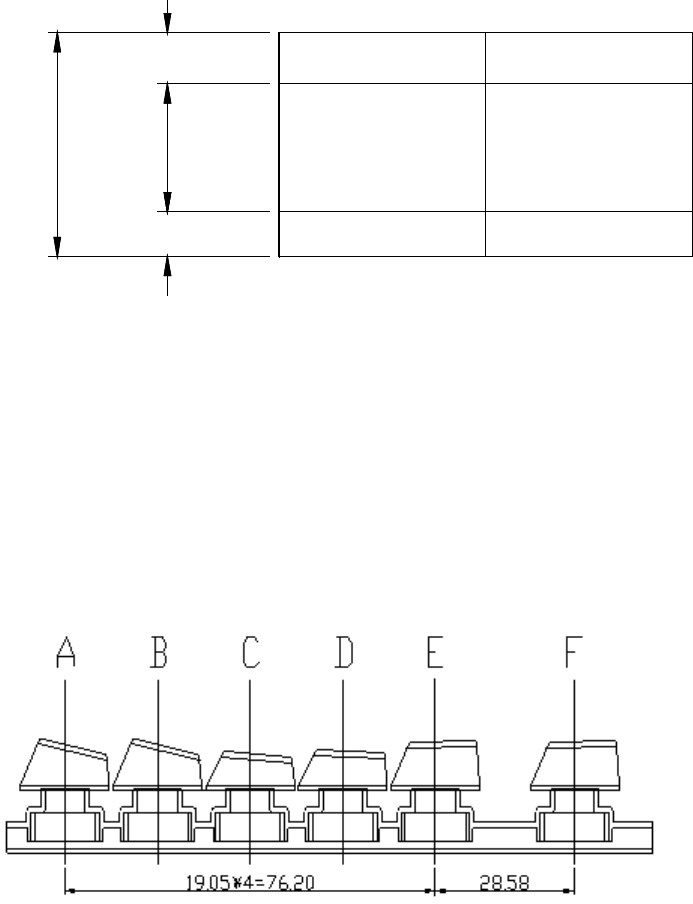
2.3 Construction and dimensions
Note: The applied keycap for “F” row is “E” row keycap.
2.4 Key top Height Variation
The key top height variation must not greater than 0.5mm when measured between the
center to center of keys next to each other. The measurement will be performed with keys
2.0mm
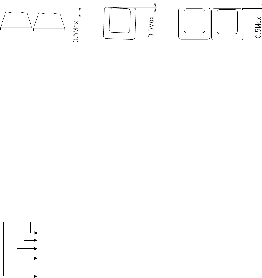
in the home positions.
2.5 Keytop Alignment
The key top alignment tolerances must not exceed 0.5mm when keytop measured
between the center to center of keys next to each other. The measurement will be
performed with keys in the home positions.
2.6 Rotational Alignment
The maximum rotation of key shall be less than 0.5mm as shown below.
Rotational Alignment Alignment
Height variation
2.7 End stroke strength
End stroke should withstand a static load of 500gf applied on the tip of the key stem in
the perpendicular direction for 1minute.
2.8 Keytop pulling strength
The keytop pull out force shall be 0.5Kg or more at normal temperature during initial
conditions.
The keytop shall be not pulled out by an ordinary typing operations.
2.09 Back Label
The label will be squarely aligned and securely adhered with no voids or air bubbles.
The materials used and the way of manufacture and installation will be such as to
render the label "tamper-proof," that is, the label material and adhesive combination
will be such that a label will be damaged, delaminated, or destroyed upon removal or
attempted removal. The back label will contain MIC agency symbols, model number,
part number, serial number and product of origin.
※ Serial Number Information
1 K A B 000001
Produced Quantity
Production Line
Internal LOT Number
Produced Month (A=Jan, B=Feb, C=Mar, D=Apr, E=May, F=Jun,
G=Jul, H= Aug, I=Sep, J=Oct, K=Nov, L=Dec)
Last digit of Year
3. WORKMANSHIP STANDARDS
3.1 Electrical Criteria
Electrical assemblies and components shall meet the requirements of IPC-A-610 and
J-STD-001, Class-1.
3.2 Keycap Cosmetics
The legend of keycap has to be printed with LASER MARKING methodology
by SEJIN standard and will have to pass the Sejin abrasion test.
4. ELECTRICAL REQUIREMENTS
4.1 Operating voltage range
DC 5V±0.25
4.2 Operating current
Max 100mA
4.3 Insulation resistance
More than 100M ohm at 250V DC
4.4 Contact resistance
2KΩor less
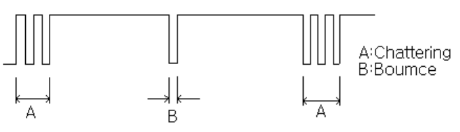
4.5 Chattering and bounce
Operation force shall be applied according to the normal operating method at 5V DC,
5mA.There shall be no bounce and chattering within 10msec when it is measured using
a specially prepared tester or a synchroscope.
※ Chattering and bounce are defined in the following diagram :
5. ENVIRONMENTAL REQUIREMENTS
The following specifications pertain to the keyboard assembly.
5.1 Operational ambient temperature and humidity
Temperature : 0 ~ 50℃
Humidity : 85%RH
5.2 Storage ambient temperature and humidity
Temperature : -20 ~ 60℃
Humidity : 95%RH
5.3 Shock
There shall be no abnormally in operation and appearance of the keyboard when an
impact of 10G has been applied to the package keyboard. The testing method shall
be in accordance with 213B of MIL-STD-202E
5.4 Vibration
The keyboard shall not be damaged electrically and mechanically when the following
vibration has been applied to the packaged keyboard. The testing method shall be in
accordance with 201A of MIL-STD-202E.
Frequency: 10~55Hz
Amplitude: 0.5mm
Direction of vibration: Direction X, Y and Z individually
Time of vibration: 2 hours
5.5 Drop Test (Non-Operating)
Purpose of test: To verify the keyboard’s ability to withstand being dropped from lap
and desk heights.
Test Parameters/Conditions: 25°C @ 50% R.H.
Standard: After test, If the keyboard is recoverable(able to be
re- assembled), it is acceptable.
Packing
Condition Drop surface Height Test Description
Hard wood 70Cm 2 drops for each corner Non-
packing Carpet 70Cm 1drop for 6 surfaces
Inner box Concrete 90Cm 1drop for 6 surfaces and 4
corners. (Totally 10drop)
Out box Concrete 60Cm 1drop for 6 surfaces and 4
corners. (Totally 10drop)
5.6 Key life Test
Standard: a. key-switch life: 10,000,000 cycles
b. Test equipment : Plunger Type.
Actuation speed : 4 times/sec
Press pressure : 200±50gf
5.7 Low Temperature Test
Check Method: Leave for 96 hours under –25℃.
Standard: The keyboard operates normally after the test.
5.8 High Temperature Test
Check Method: Leave for 96hours under +65℃.
Standard: The keyboard operates normally after the test.
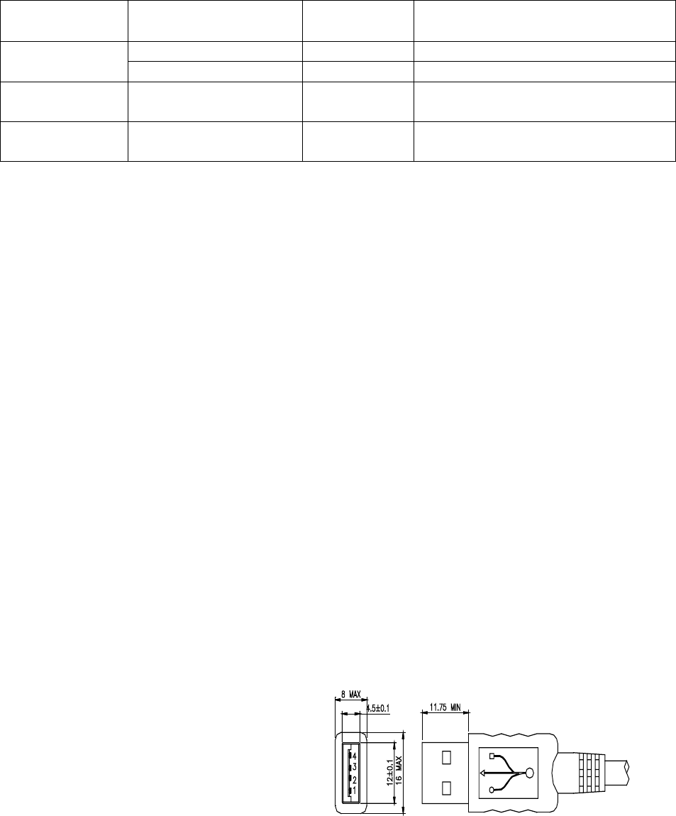
6. CONFIGURATION
The keyboard comprises the key switch section and signal processing circuit.
The keyboard cable connects to the system with a USB connector.
The following table shows the pin configuration and signal assignments.
Contact Number Signal Name
1 VBUS
2 D-
3 D+
4 GND
Shell Shield
Thanks for using SEJIN Keyboard (MODEL:SKR-4200U)
THE SEJIN Keyboard
Designed with the users in mind, it has a pleasant appearance and is Convenient to use.
No extra power supply is required.
It is compatible with the Microsoft Keyboard.
Mini-keyboard INSTALLATION
Turn the power supply off to your computer.
Check the USB keyboard/mouse port at the back of your computer and insert
The connector at the end of the Key-board cables into the usb port .
Turn the power supply on to your computer.
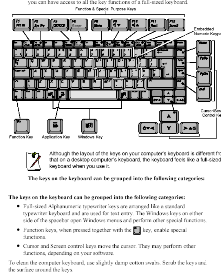
Using the Keyboard
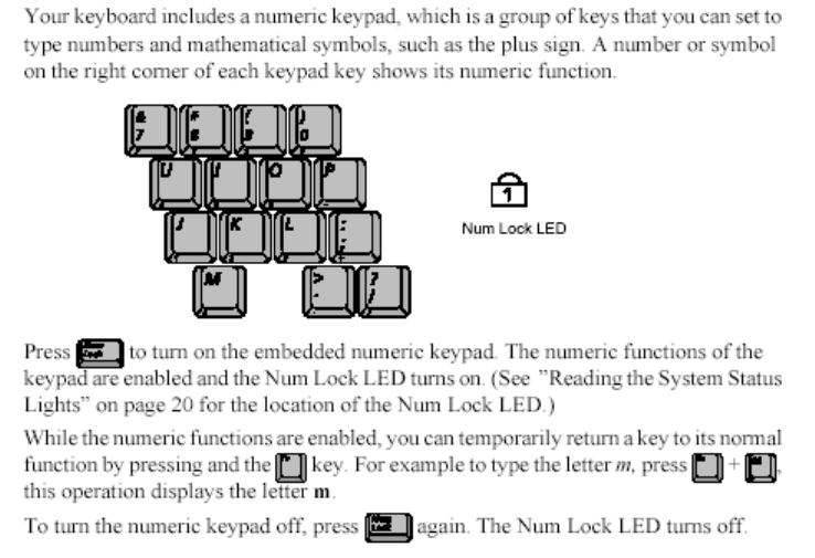
Using the Numeric KeyPad
FCC NOTICE
THIS DEVICE COMPLIES WITH PART 15 OF THE FCC RULES.
OPERATION IS SUBJECT TO THE FOLLOWING TWO CONDITION:
(1) THIS DEVICE MAY NOT CAUSE HARMFUL INTERFERENCE, AND
(2) THIS DEVICE MUST ACCEPT ANY INTERFERENCE RECEIVED,
INCLUDING INTERFERENCE THAT MAY CAUSE UNDERSIRED
OPERATION.
This equipment has been tested and found to comply with the limits for a Class B
digital device, pursuant to part 15 of the FCC Rules. These limits are designed to
provide reasonable protection against harmful interference in a residential installation.
This equipment generates, uses and can radiate radio frequency energy and, if not
installed and used in accordance with the instructions, may cause harmful interference
to radio communication. However, there is no guarantee that interference will not
occur in a particular installation. If this equipment does cause harmful interference to
radio or television reception, which can be determined by turning the equipment off and
on, the user is encouraged to try to correct the interference by one or more of the
following measures :
- Reorient or relocate the receiving antenna.
- Increase the separation between the equipment and receiver.
- Connect the equipment into an outlet on a circuit difference from that to which
the receiver is connected.
- Consult the dealer of an experienced radio/TV technician for help.
NOTE : The manufacturer is not responsible for any radio or TV interference caused by
unauthorized modifications to this equipment. Such modifications could void the user’s
authority to operate the equipment.