Se Jin Electron SKS-4210UH USB Keyboard User Manual
Se Jin Electron Inc USB Keyboard
User Manual
SEJIN ELECTRON, INC
SEJIN confidential - Copyright© Sejin electron, Inc. 2009.
This Document contains proprietary to Sejin Electron, Inc. Use or disclosure without written
permission from an officer of Sejin is expressly forbidden.
Document number : R-FB-0 Page 1/13 Issued date : 2009-02-11
SPECIFICATIONS
for
SEJIN USB Keyboard with articulation
V1.0
Model Name SKS-4210UH
P / N
USER P / N
TYPE
Description
Specification No R-FB-0
Issued Mechanical
checking
Electrical
checking
Approved

SEJIN ELECTRON, INC
SEJIN confidential - Copyright© Sejin electron, Inc. 2009.
This Document contains proprietary to Sejin Electron, Inc. Use or disclosure without written
permission from an officer of Sejin is expressly forbidden.
Document number : R-FB-0 Page 2/13 Issued date : 2009-02-11
Contents
1 Revision History...............................................................................................................4
2 Scope................................................................................................................................. 4
3 Features.............................................................................................................................4
4 Mechanical Specifications................................................................................................4
4.1 General ......................................................................................................................................... 4
4.2 Key switch Operation................................................................................................................... 4
4.3 Operating Region ......................................................................................................................... 6
4.4 Key-top Deflection....................................................................................................................... 6
4.5 Operating feeling.......................................................................................................................... 6
4.6 Key-top Height Variation............................................................................................................. 6
4.7 Tilt................................................................................................................................................ 6
4.8 Key-top Alignment....................................................................................................................... 7
4.9 Rotational Alignment ................................................................................................................... 7
4.10 End stroke strength....................................................................................................................... 7
4.11 Key-top pull out force .................................................................................................................. 7
4.12 Information for serial number on the back label .......................................................................... 7
5 Electrical Specification..................................................................................................... 8
5.1 Power supply voltage ...................................................................................................................8
5.2 Power supply current consumption.............................................................................................. 8
5.3 Insulation resistance..................................................................................................................... 8
5.4 Chattering and bounce.................................................................................................................. 8
5.5 Cable length ................................................................................................................................. 8
5.6 Contact terminating assignment. .................................................................................................. 8
5.7 USB Soft Ware I/F....................................................................................................................... 8
5.8 USB HUB..................................................................................................................................... 9
6 Environmental Characteristic ...........................................................................................9
6.1 Operational ambient temperature and humidity ........................................................................... 9
6.2 Storage ambient temperature and humidity.................................................................................. 9
7 Environmental Performance.............................................................................................9
7.1 Shock............................................................................................................................................ 9
7.2 Vibration ...................................................................................................................................... 9
7.3 Heat Cycle Test.......................................................................................................................... 10
7.4 Key life Test............................................................................................................................... 10
7.5 Low Temperature Test ............................................................................................................... 10
7.6 High Temperature Test............................................................................................................... 10

SEJIN ELECTRON, INC
SEJIN confidential - Copyright© Sejin electron, Inc. 2009.
This Document contains proprietary to Sejin Electron, Inc. Use or disclosure without written
permission from an officer of Sejin is expressly forbidden.
Document number : R-FB-0 Page 3/13 Issued date : 2009-02-11
8 Keyboard Layout ............................................................................................................11
9 Block Diagram................................................................................................................12
10 Information to the user....................................................................................................13
SEJIN ELECTRON, INC
SEJIN confidential - Copyright© Sejin electron, Inc. 2009.
This Document contains proprietary to Sejin Electron, Inc. Use or disclosure without written
permission from an officer of Sejin is expressly forbidden.
Document number : R-FB-0 Page 4/13 Issued date : 2009-02-11
1 Revision History
Rev. No Issued date & Descriptions Date Issued by Checked by
Ver 1.0 Initially released 2009-02-11 S. R, Hong
2 Scope
This document describes a specification for “Key-Obeation” USB Keyboard
3 Features
● Low profile Ergonomic Keyboard with articulation
● High-Speed USB2.0
● Scissor – Switch technology
● Functionality: Microsoft Windows Vista & MAC OS
● Quite tactile feel
● Nun-skid rubber feet
● Built-in a USB port on right side of the keyboard for plugging in your mouse and
Other USB devices
● Pseudo N- key roll over
4 Mechanical Specifications
4.1 General
Keyswitch type Membrane & rubber contact with Quiet tactile feel
Number of keys 90 keys
Keyswitch life 2,000,000 cycles
Key travel (Full stroke) 2.5±0.5 mm
Operating force 45±15gf
Dimension 345.2 x 129.1 x 25.5 mm (13.5 x 5.0 x 1.0 in)
4.2 Key switch Operation
Key switch operating parameters should comply with those listed below.
Figure on the below represents typical pressure force and displacement values acceptable to SEJIN.
SEJIN ELECTRON, INC
SEJIN confidential - Copyright© Sejin electron, Inc. 2009.
This Document contains proprietary to Sejin Electron, Inc. Use or disclosure without written
permission from an officer of Sejin is expressly forbidden.
Document number : R-FB-0 Page 5/13 Issued date : 2009-02-11
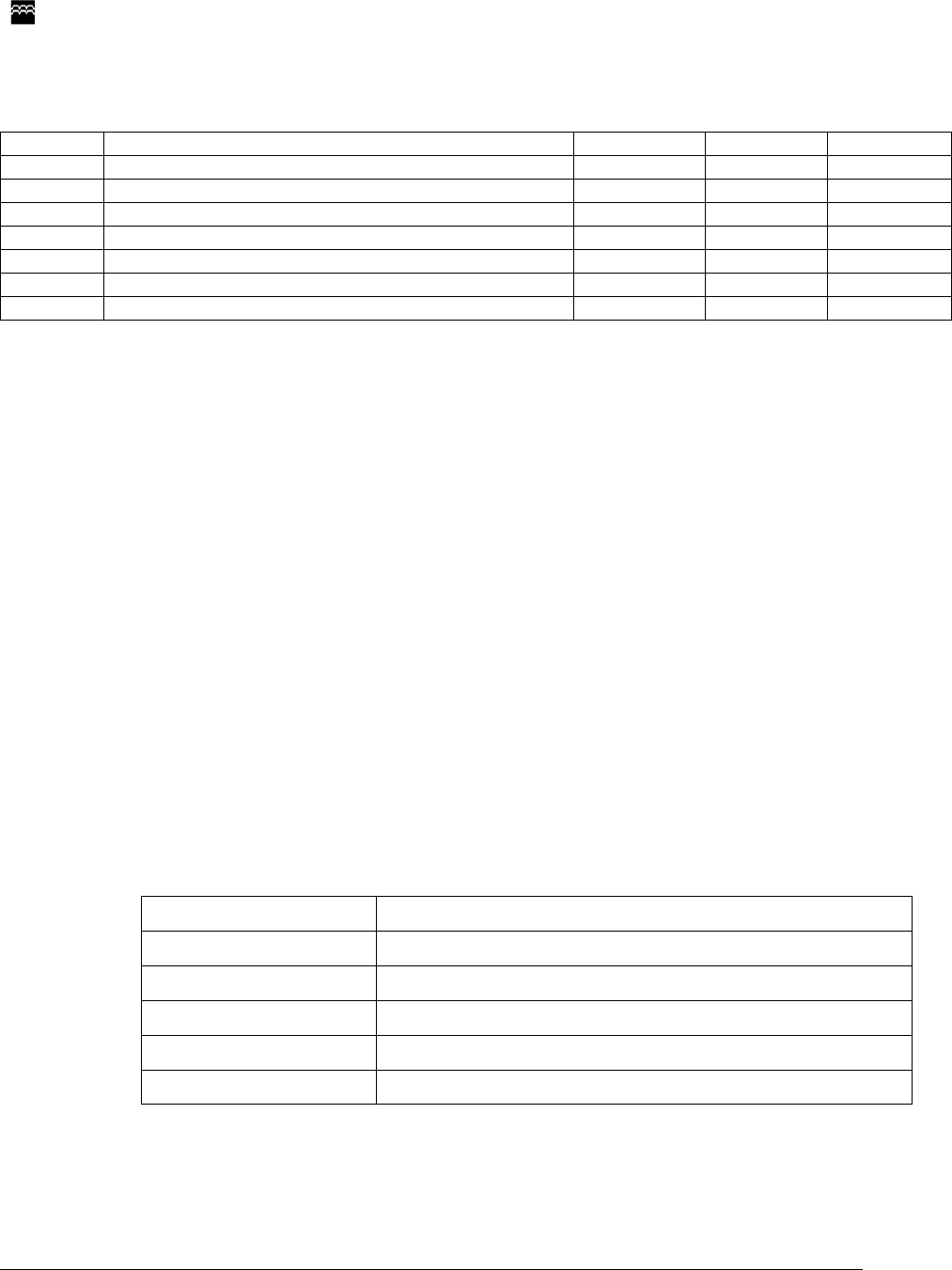
The force/displacement curve should not exhibit any significant step or plateau from P2 to the end of
full travel. Linear measures are in mm and the values represent the force and displacement of a key
switch after it has been preloaded by 10 to 20 grams.
Standard: a. Non-lock rubber tactile feeling
b. P0 (Preloaded Point)
Travel = 0 mm / Force = 10 +10/-5 grams
c. P1 (Break over Point)
Travel = 0.8 ± 0.3 mm / Force = 45 ± 15 grams
d. P2 (Make Point)
Travel = 1.75 ± 0.95 mm / Force = P1 - Delta
Delta = 45% to 60% of the P1 force, but 20 grams minimum.
e. P3 (Normally End Point)
Travel = 2.5 ± 0.5 mm / Force = P1 + 10 to 15 grams
Check Point: a. Operating feeling: No definite stickiness or other abnormality shall be allowed. When
force is applied with a finger on the key-top center at the rate of three times a second.
b. Key-top pulling strength: A key-top should come off after applying a force of 0.5Kg to
8Kg range in the vertical direction.
SEJIN ELECTRON, INC
SEJIN confidential - Copyright© Sejin electron, Inc. 2009.
This Document contains proprietary to Sejin Electron, Inc. Use or disclosure without written
permission from an officer of Sejin is expressly forbidden.
Document number : R-FB-0 Page 6/13 Issued date : 2009-02-11
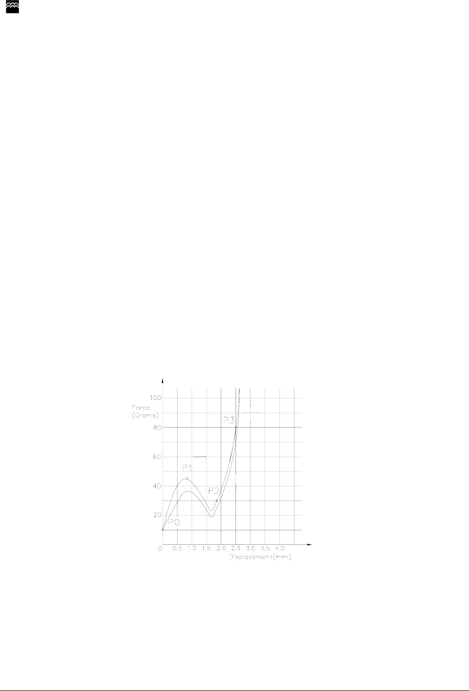
4.3 Operating Region
ON/OFF
Swithing
region
0.5mm
1.2mm
0.8mm
Total
traval
2.5mm
Bottom end
Top end
ON region
OFF region
4.4 Key-top Deflection
Key-top deflection to on side shall be 0.8mm or less.
4.5 Operating feeling
No definite stickiness or other abnormality shall be allowed when force is applied with a finger to Key-
top center at the rate of 3 times a second.
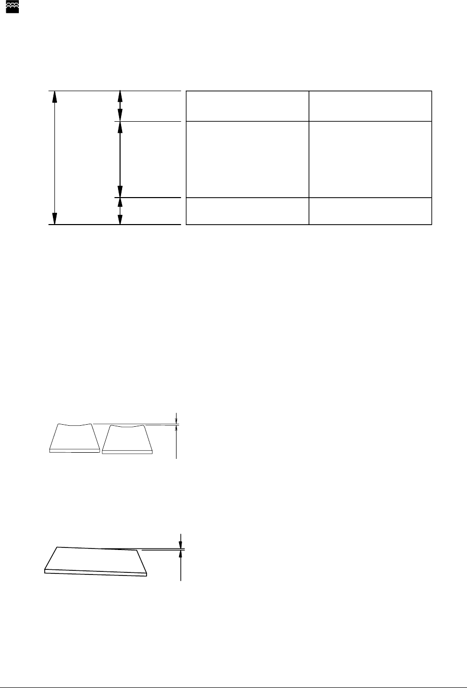
4.6 Key-top Height Variation
The key top height variation must not greater than 0.5mm when measured between the center to
center of keys next to each other. The measurement will be performed with keys in the home positions.
0.5mm Max
4.7 Tilt
The keys must not exhibit tilt greater than 0.5mm.for the 1x1 key top, 0.6mm for the 1x1.25 key top
and 0.7mm for the 1x1.5 key
A<0.5mm (1x1, 0.75(FUN) key)
< 0.6mm (1x1.25, 1.5 key)
<0.7mm (1x1.75, 4.25 key)
SEJIN ELECTRON, INC
SEJIN confidential - Copyright© Sejin electron, Inc. 2009.
This Document contains proprietary to Sejin Electron, Inc. Use or disclosure without written
permission from an officer of Sejin is expressly forbidden.
Document number : R-FB-0 Page 7/13 Issued date : 2009-02-11
4.8 Key-top Alignment
The key top alignments will not exceed 0.5mm when top measured between the center to center of
keys next to each other. The measurement will be performed with keys in the home positions.
0.5 mm Max
4.9 Rotational Alignment
The maximum rotation of key shall be less than 0.5mm as shown below.
A
<0.5mm (1X1.75 Unit key Max)
0.7mm(1X2 Unit key Max)
4.10 End stroke strength
End stroke should withstand a static load of 500gf applied on the tip of the key stem in the
perpendicular direction for 1minute.
4.11 Key-top pull out force
The Key-top pull out force shall be 0.5kg or more at normal temperature during initial state. The Key-
top shall be not pull out by an ordinary typing operation.
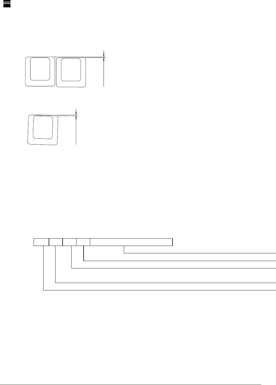
4.12 Information for serial number on the back label
0 C A C 0 0 0 0 0 3
Serial No.
Production line(A=A line, B=B line, C=C line)
Product revision number(A~Z)
Produced Month (A~Z)(A=Jan, B=Feb, C=Mar, D=Apr, E=May, F=June,
G=July, H=Aug, I=Sept, J=Oct, K=Nov, L=Dec)
Last Digit of Year(7=2007, 8=2008, 9=2009)
SEJIN ELECTRON, INC
SEJIN confidential - Copyright© Sejin electron, Inc. 2009.
This Document contains proprietary to Sejin Electron, Inc. Use or disclosure without written
permission from an officer of Sejin is expressly forbidden.
Document number : R-FB-0 Page 8/13 Issued date : 2009-02-11
5 Electrical Specification
5.1 Power supply voltage
DC 5.0V
5.2 Power supply current consumption
Max 500mA
5.3 Insulation resistance
More than 100M ohm at 250V DC
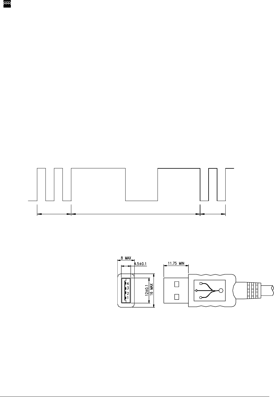
5.4 Chattering and bounce
Operation force shall be applied according to the normal operating method at 5V DC, 5mA.There shall
be no bounce and chattering within 10msec when it is measured using a specially prepared tester or a
synchroscope.
※ Chattering and bounce are defined in the following diagram :
A:Chattering
B: Bounce
A
B
A
5.5 Cable length
1.6m (Straight)
5.6 Contact terminating assignment.
Contact Number Signal Name
1 VBUS
2 D-
3 D+
4 GND
Shell Shield
5.7 USB Soft Ware I/F
Compliant with USB Serial Bus Specification 2.0
High speed USB standard for USB HUB
Low speed USB standard for keyboard interface (Revision 1.1 September 23, 1998)

SEJIN ELECTRON, INC
SEJIN confidential - Copyright© Sejin electron, Inc. 2009.
This Document contains proprietary to Sejin Electron, Inc. Use or disclosure without written
permission from an officer of Sejin is expressly forbidden.
Document number : R-FB-0 Page 9/13 Issued date : 2009-02-11
5.8 USB HUB
Bus powered USB 2.0 high speed USB HUB functionality
One internal USB port is used for keyboard
One USB 2.0 high speed downstream port is available for external low power USB devices
The external USB devices that attached on the downstream ports must be low power USB devices
which maximum 100mA of power current
6 Environmental Characteristic
6.1 Operational ambient temperature and humidity
Temperature : 0 ~ 40℃
Humidity: 85%RH (without condensation)
6.2 Storage ambient temperature and humidity
Temperature : -20 ~ 50℃
Humidity: 95%RH
7 Environmental Performance
7.1 Shock
There shall be no abnormally in operation and appearance of the keyboard when an impact of 10G
has been applied to the package keyboard. The testing method shall be in accordance with 213B of
MIL-STD-202E
7.2 Vibration
The keyboard shall not be damaged electrically and mechanically when the following vibration has
been applied to the packaged keyboard. The testing method shall be in accordance with 201A of MIL-
STD-202E.
Frequency: 10~55Hz
Amplitude: 0.5mm
Direction of vibration: Direction X, Y and Z individually
Time of vibration: 2 hours
SEJIN ELECTRON, INC
SEJIN confidential - Copyright© Sejin electron, Inc. 2009.
This Document contains proprietary to Sejin Electron, Inc. Use or disclosure without written
permission from an officer of Sejin is expressly forbidden.
Document number : R-FB-0 Page 10/13 Issued date : 2009-02-11
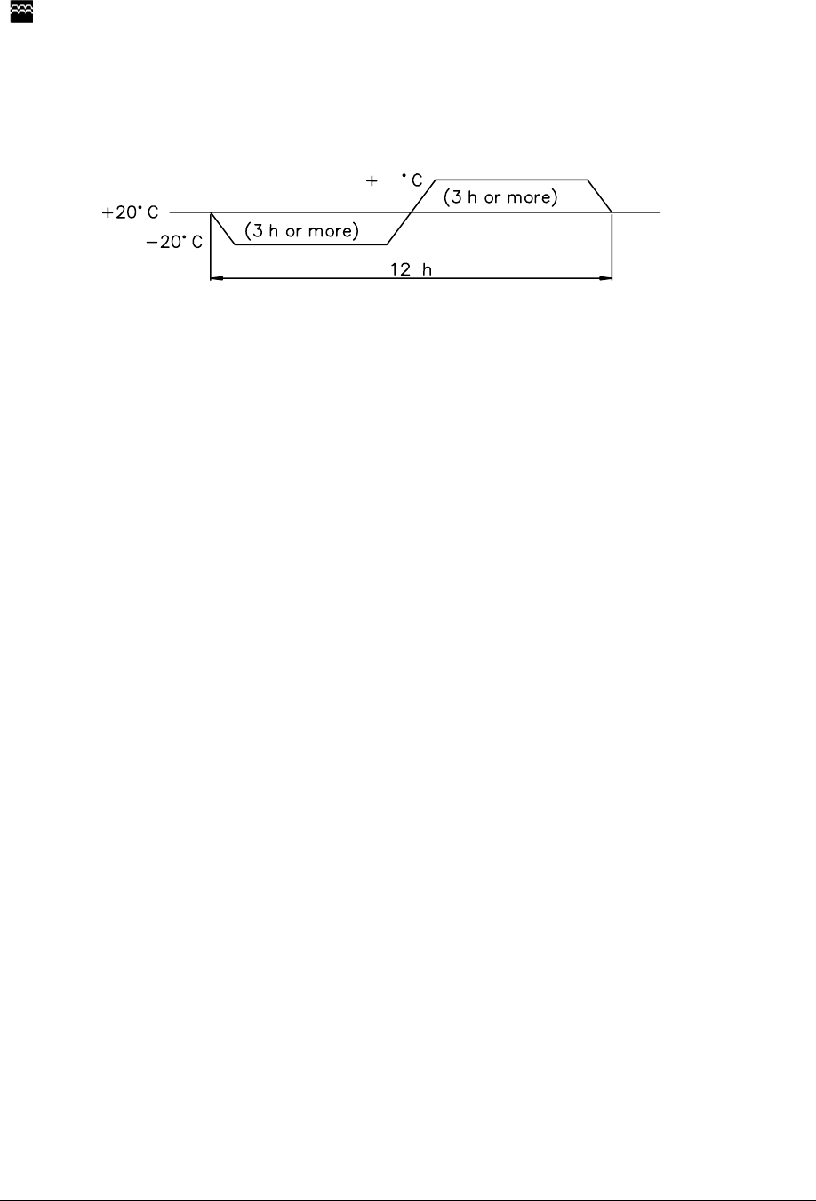
7.3 Heat Cycle Test
Check Method: By the condition shown in the figure below, repeat heat cycle test for 2 times.
50
Standard: When the test is finished, followings must be satisfied.
a. All functions operate normally.
b. There are no defects which harm commercial value, e.g., change of color, rust or
change of form.
7.4 Key life Test
Standard: a. key-switch life: 2,000,000 cycles
b. Keyboard is qualified using Hasco pneumatic life tester using soft cushion actuator with
a 4cycles / second actuation speed 120 ~ 150gf air pressure.
7.5 Low Temperature Test
Check Method: Leave for 96 hours under –20℃.
Standard: The keyboard operates normally after the test.
7.6 High Temperature Test
Check Method: Leave for 96hours under +50℃.
Standard: The keyboard operates normally after the test.
SEJIN ELECTRON, INC
SEJIN confidential - Copyright© Sejin electron, Inc. 2009.
This Document contains proprietary to Sejin Electron, Inc. Use or disclosure without written
permission from an officer of Sejin is expressly forbidden.
Document number : R-FB-0 Page 11/13 Issued date : 2009-02-11
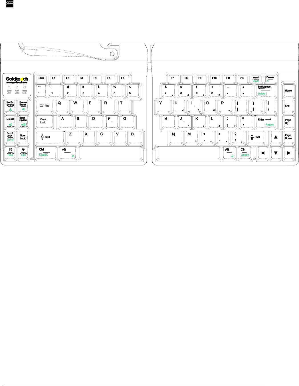
8 Keyboard Layout
SEJIN ELECTRON, INC
SEJIN confidential - Copyright© Sejin electron, Inc. 2009.
This Document contains proprietary to Sejin Electron, Inc. Use or disclosure without written
permission from an officer of Sejin is expressly forbidden.
Document number : R-FB-0 Page 12/13 Issued date : 2009-02-11
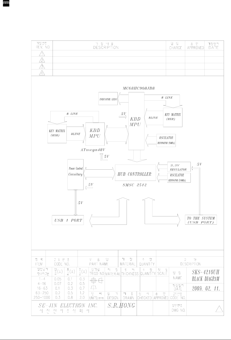
9 Block Diagram

SEJIN ELECTRON, INC
SEJIN confidential - Copyright© Sejin electron, Inc. 2009.
This Document contains proprietary to Sejin Electron, Inc. Use or disclosure without written
permission from an officer of Sejin is expressly forbidden.
Document number : R-FB-0 Page 13/13 Issued date : 2009-02-11
10 Information to the user
Note: This equipment has been tested and found to comply with the limits for a Class
B digital device, pursuant to part 15 of the FCC Rules. These limits are designed to
provide reasonable protection against harmful interference in a residential
installation. This equipment generates, uses and can radiate radio frequency
energy and, if not installed and used in accordance with the instructions, may
cause harmful interference to radio communications. However, there is no
guarantee that interference will not occur in a particular installation. If this
equipment does cause harmful interference to radio or television reception, which
can be determined by turning the equipment off and on, the user is encouraged to
try to correct the interference by one or more of the following measures:
- Reorient or relocate the receiving antenna.
- Increase the separation between the equipment and receiver.
- Connect the equipment into an outlet on a circuit different from that to which the
receiver is connected.
- Consult the dealer or an experienced radio/TV technician for help.
Modifications not expressly approved by the manufacturer could void the user's
authority to operated the equipment under FCC rules.
-----The end of specification-----