Sealed Air DRX 13.56MHz RFID TRANSMITTER WITH USB INTERFACE User Manual Cryovac Inc
Sealed Air Corp. 13.56MHz RFID TRANSMITTER WITH USB INTERFACE Cryovac Inc
UserManual.wiki
>
Sealed Air
>
DRX User Manual
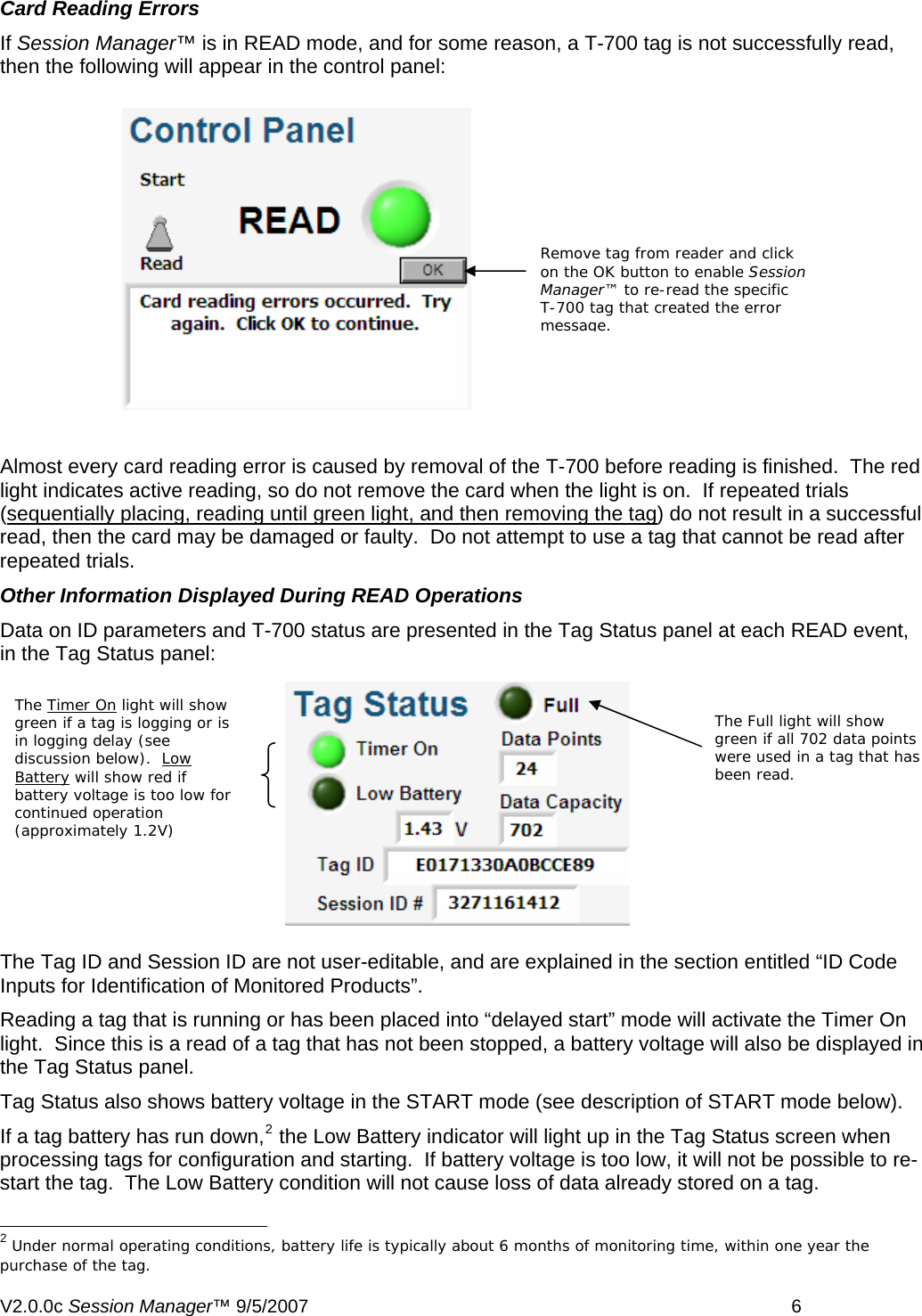
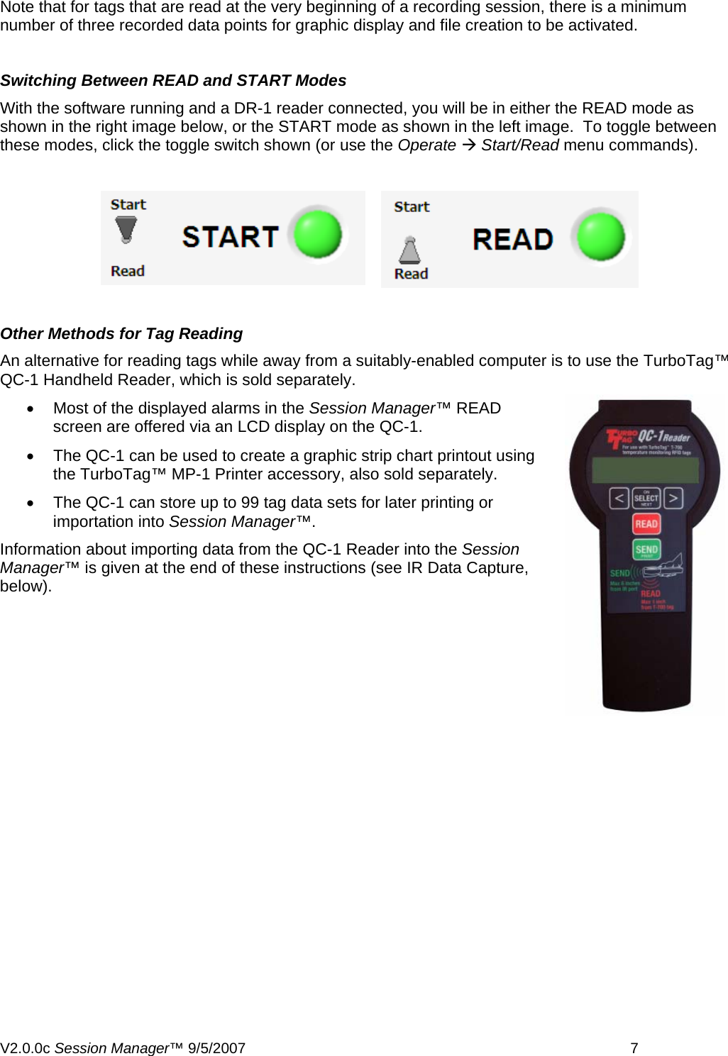
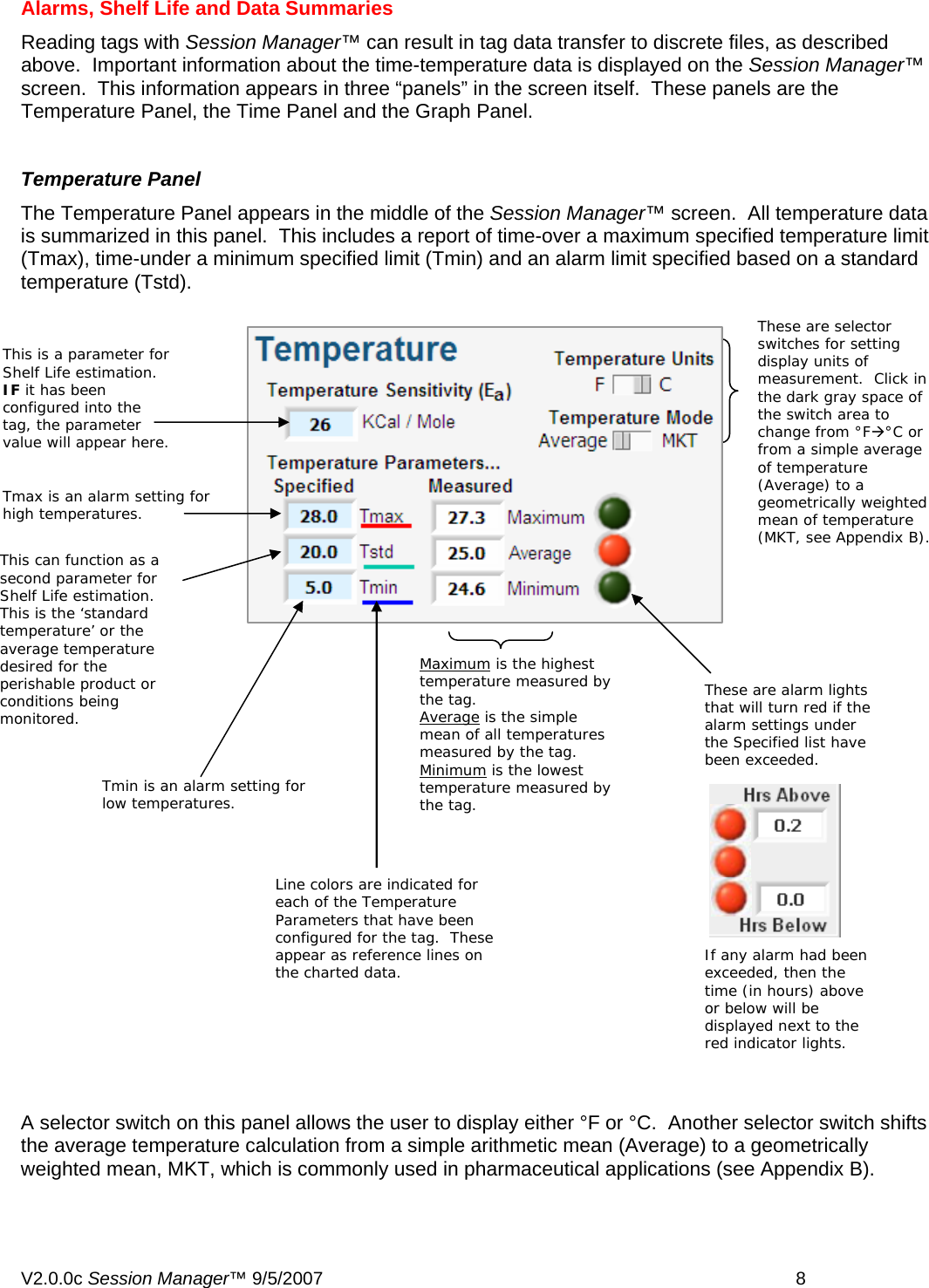
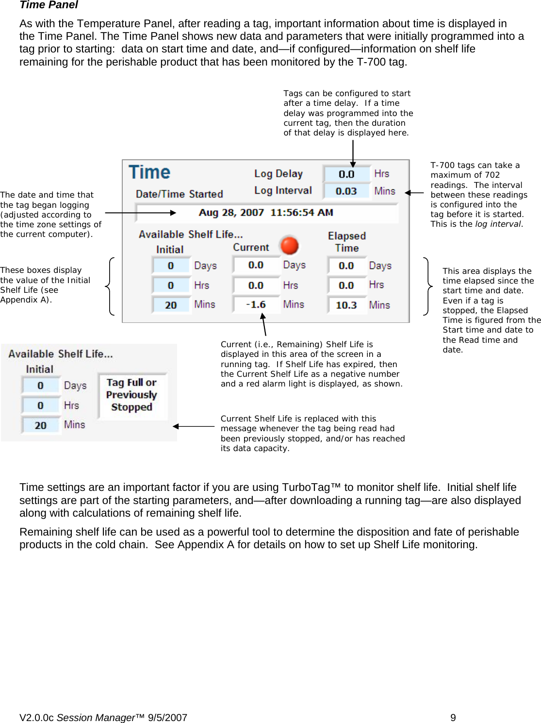
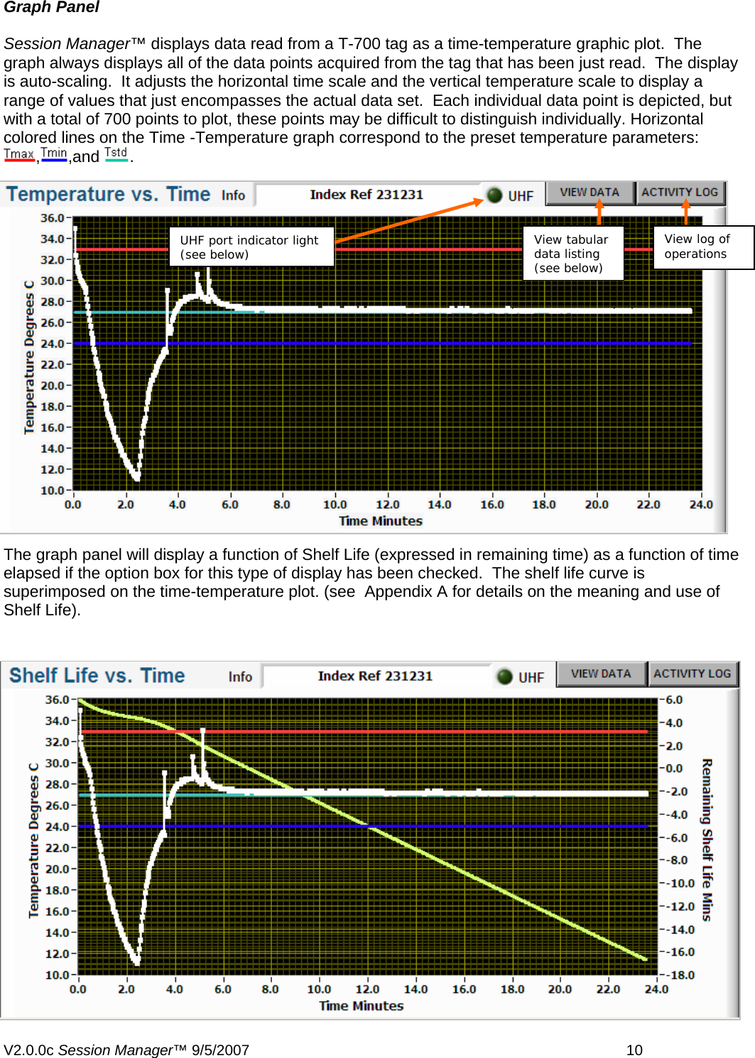
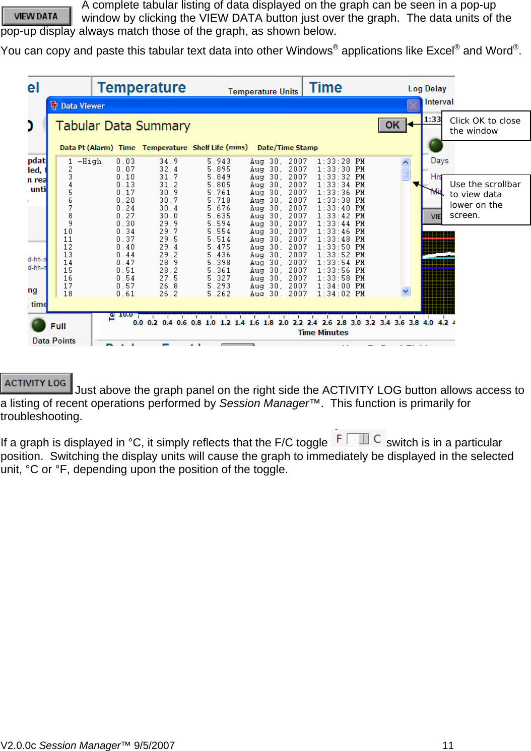
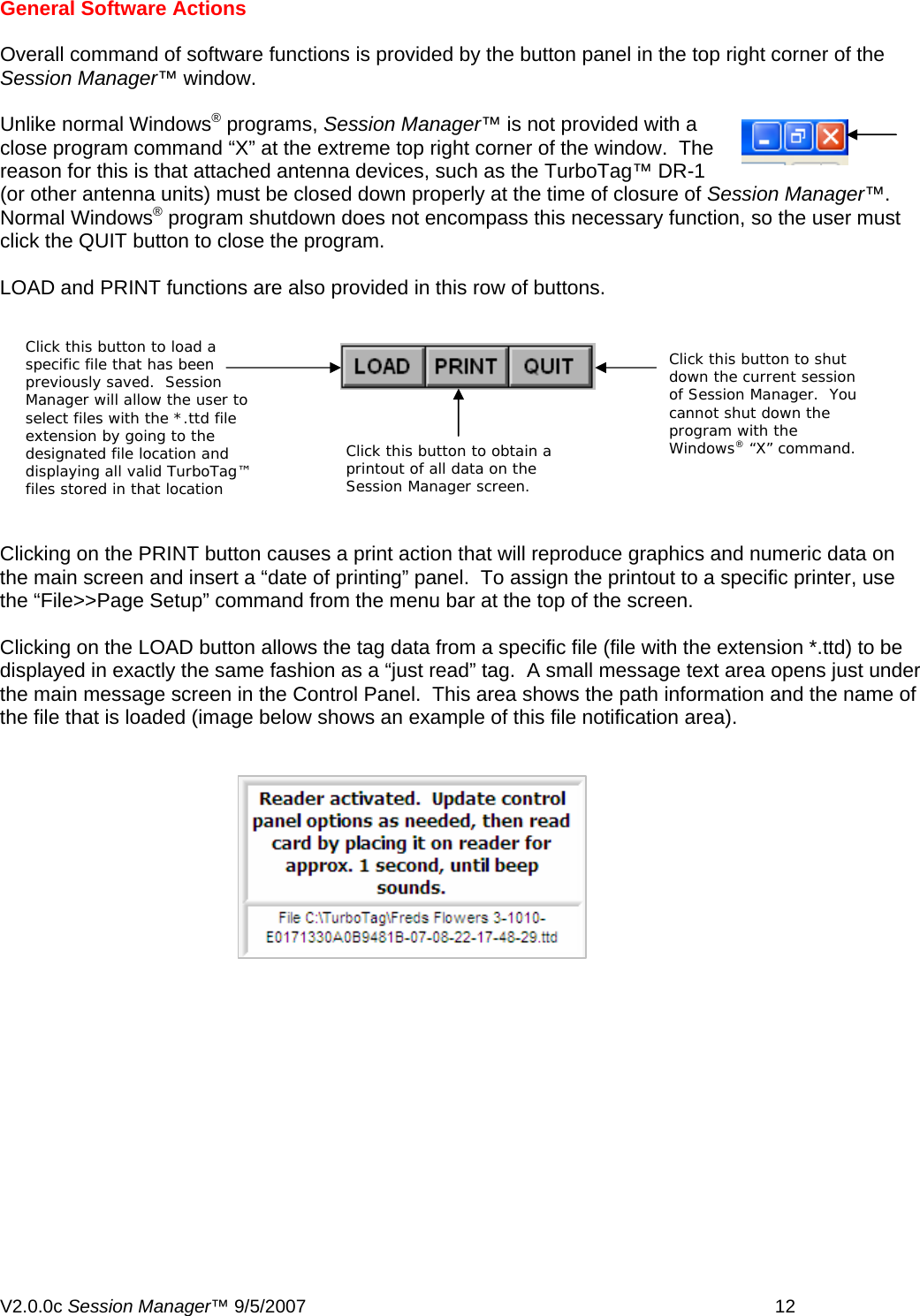
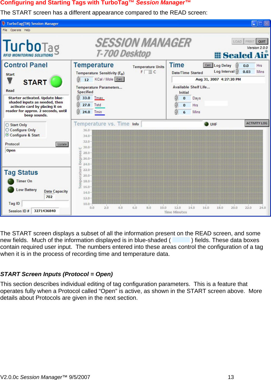
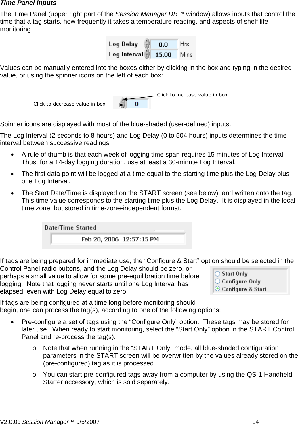
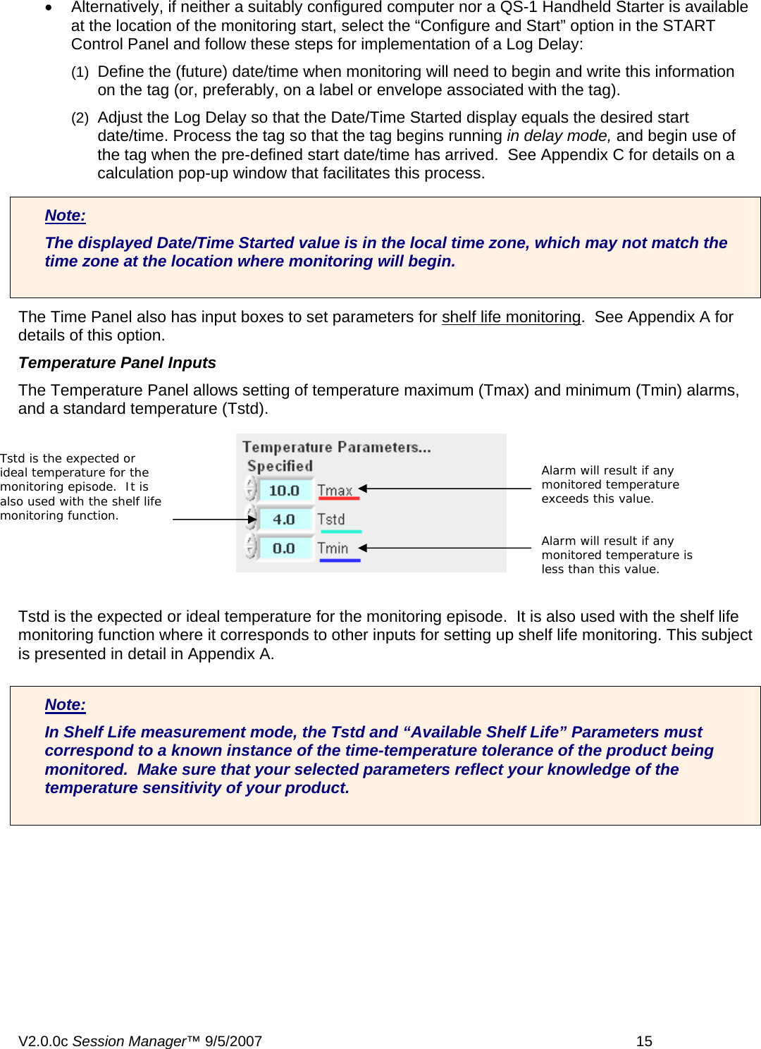
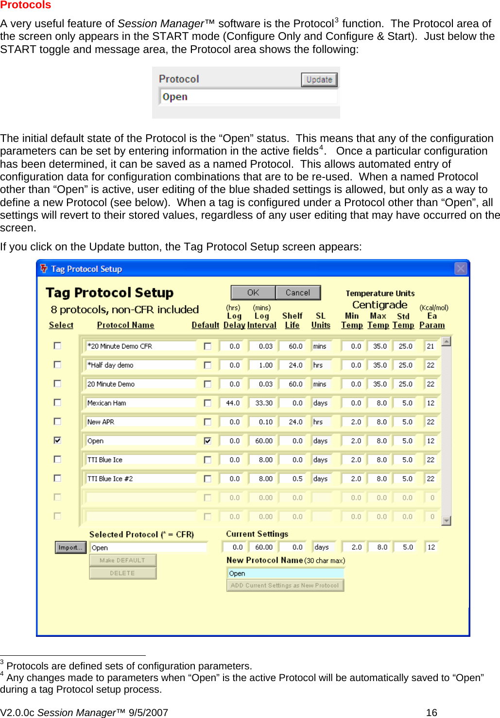
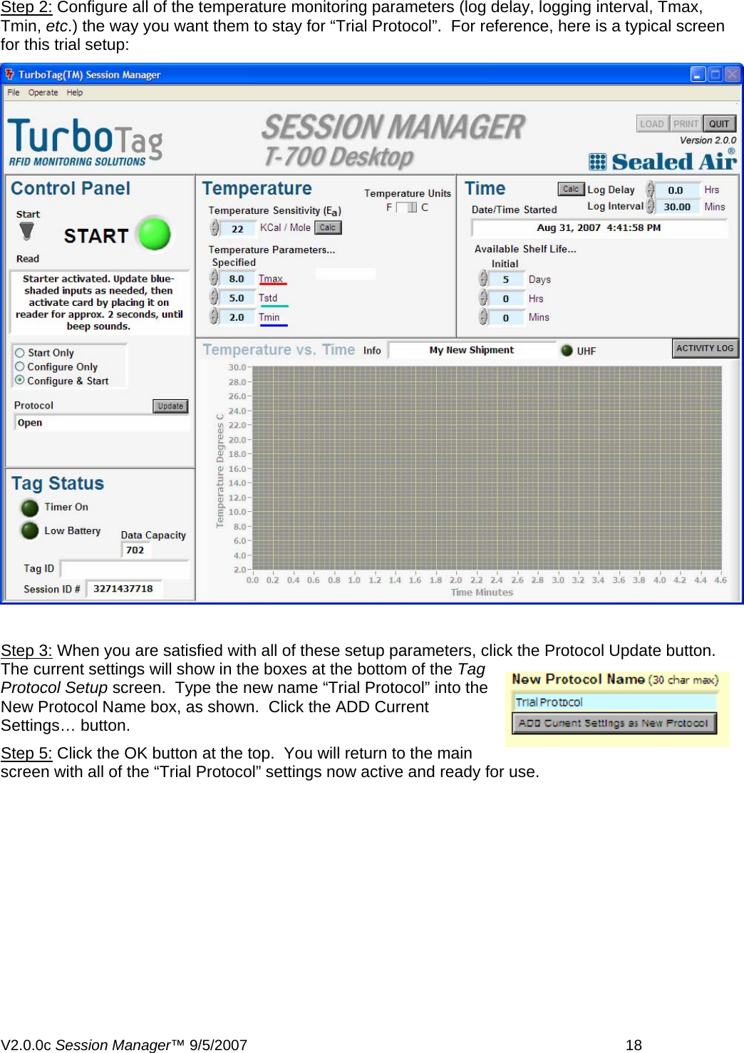
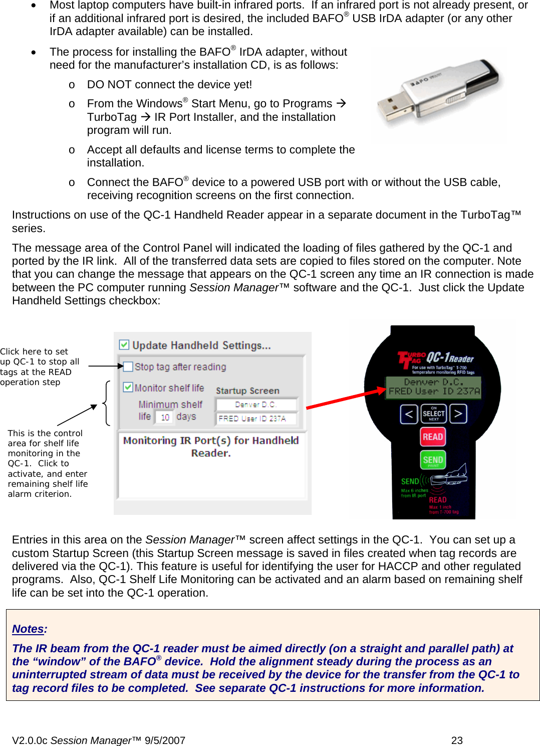
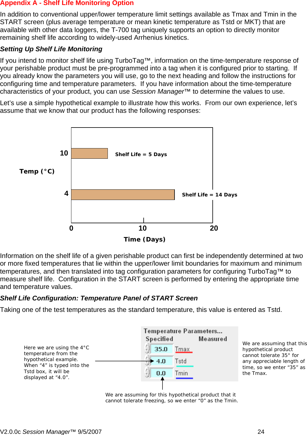
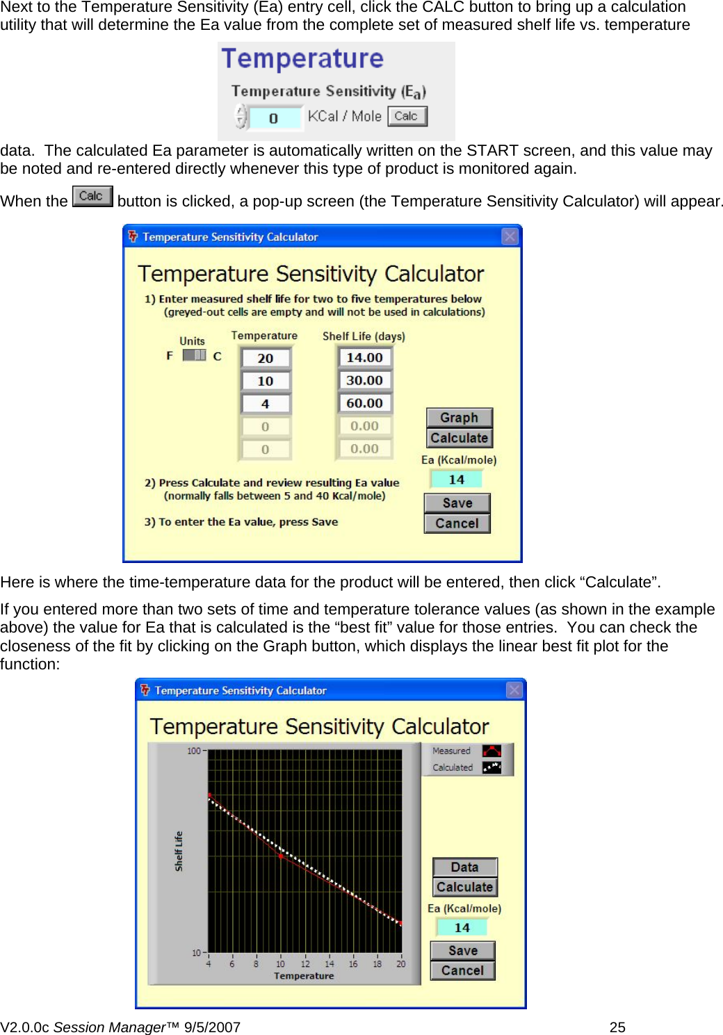
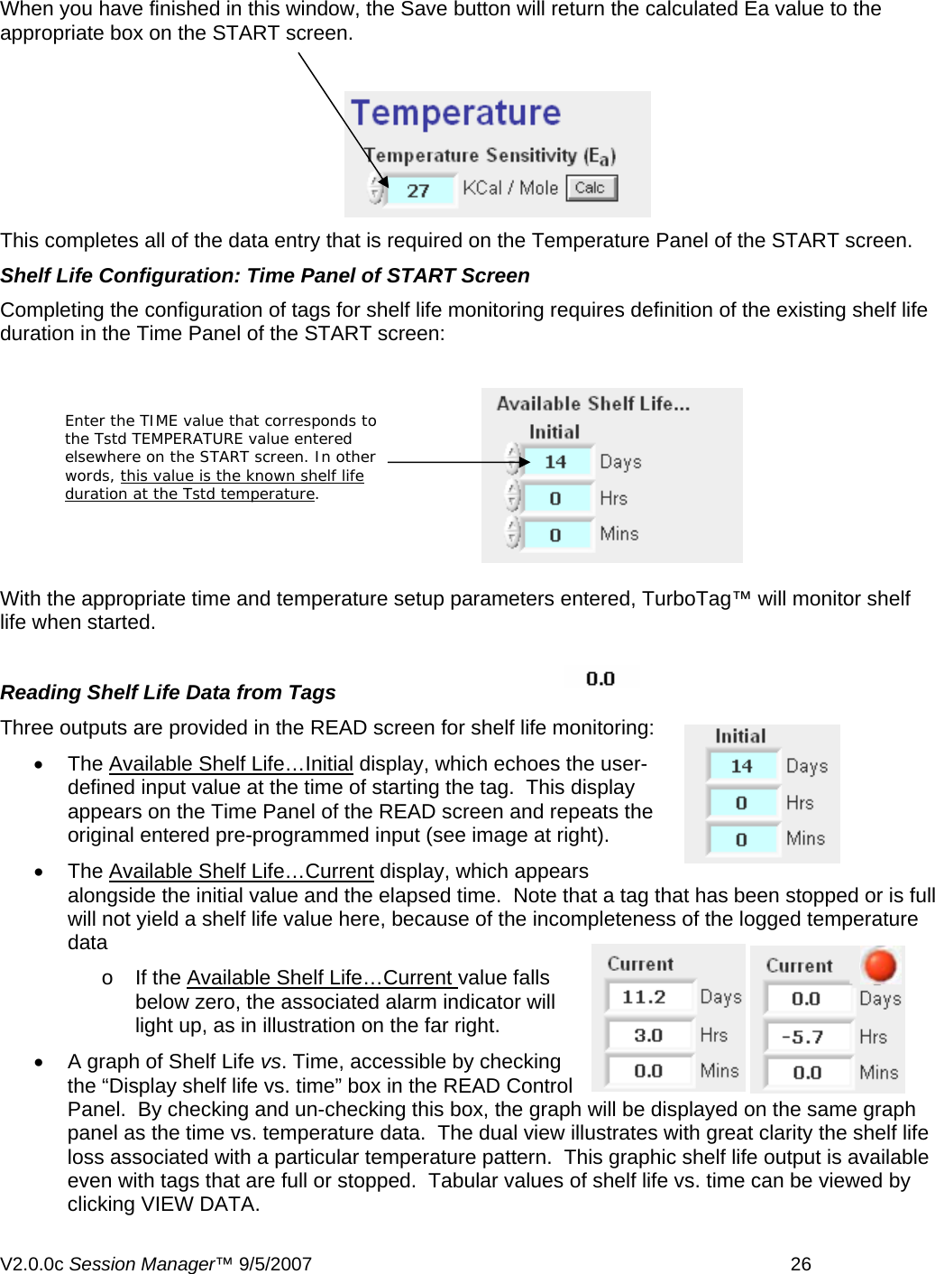
USERS MANUAL
Navigation menu
Upload a User Manual
Namespaces
Wiki Guide
HTML
PDF
Info
Views
User Manual
Discussion / Help
Navigation