Sears 113 23611 Users Manual
113236110 113236110 CRAFTSMAN 16 INCH SCROLL SAW - Manuals and Guides L0903184 View the owners manual for your CRAFTSMAN 16 INCH SCROLL SAW #113236110. Home:Tool Parts:Craftsman Parts:Craftsman 16 INCH SCROLL SAW Manual
CRAFTSMAN Saw Scroll Manual L0903184 CRAFTSMAN Saw Scroll Owner's Manual, CRAFTSMAN Saw Scroll installation guides
113.23611 to the manual 92ec8cf1-e927-43c8-9400-68d9eb65fcae
2015-02-05
: Sears Sears-113-23611-Users-Manual-399421 sears-113-23611-users-manual-399421 sears pdf
Open the PDF directly: View PDF ![]() .
.
Page Count: 20
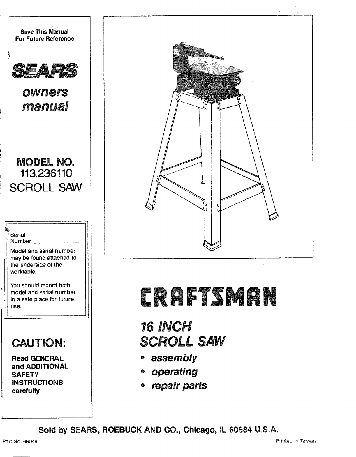
Save This:Manual
For Future Reference
MODEL NO.
113.236!10
SCROLL SAW
! Serial
Number
Model and serial number
may be found attached to
the underside of the
worktable.
You should record both
model and serial number
in a safe place for future
use.
CAUTION:
Read GENERAL
and ADDITIONAL
SAFETY
INSTRUCTIONS
carefully
16 INCH
SCROLL
o assembly
ooperating
®repair parts
Sold by SEARS, ROEBUCK AND CO., Chicago, IL 60684 U.S.A.
Part No, 66048 Printed in T_{war_

_:,::_ :::/, . - ) : : :: : :, .
SCROLL SAW
.=to adefect in material or
--I'SMAN SCROLL SAW TO THE NEAREST
tN THE UNITED STATES.
also have other rights which vary from state to
Seam Tower; BSC 41-3, Chicago, fill®is 60884
general safety instructions for power teems
1. KNOW YOUR POWER TOOL
Read and understand the owner's manual and labels
affixed to the toot. Learn its application and limitationsas
well as the specific potential hazards pecutiar to thistool.
2. GROUND ALL TOOLS
This tool is equipped with an approved 3-conductor cord
and a 3_prong grounding type plug to fit the proper
groundir_g type receptacle. The green conductor in the
cord is the grounding wire. Never connect the green wire
to a live terminal.
3; KEEPGUARDS IN PLACE
--in working order, and place adjustment and alignment.
4. REMOVE ADJUSTING KEYS AND WRENCHES
Form'a habit of checking to see that keys and adjusting
wrenches are removed from tool before turning it on.
5, KEEP WORK AREA CLEAN
Cluttered areas and benches invite accidents. Floor must
notbe slippery due towax or sawdust.
6,: AVOID DANGEROUS ENVIRONMENT
7. KEEP CHILDREN AWAY ..... =
All Visitorsshoutd be kept a safe distance from workarea;
8. MAKE WORKSHOP CHILD PROOF : :
with padlocks, master switches, or by removingstarter
keys.
9. DON'T FORCE TOOL
It will do the job better and safer at the rate fo{"which it
was designed.
USE RIGHT TOOL
Don't force tool or attachment to do a job it was not
designed for.
WEAR PROPER APPAREL
Do not wear loose clothing, gloves, neckties or jewelry
(rings, wristwatches) to get caught in moving parts.
NONSLIP footwear is recommended. Wear protective
hair covering to contain long hair.RGII longsleeves above
the elbow.
10.
!1.
12; USE SAFETY GOGGLES (Head Protection)
Wear safety goggles (must comply with ANSI Z87.1)at all
times; ,Everyday eyeglasses only have impact resistant
lens. the/are NOT safety glasses." Also, use face or dust
mask if cutting operation is dusty, and ear protectors
(plugs or muffs) during extended periods of operation.
13. SECURE WORK
Use clamps or a vise to hold work when practical. It's
safer than using your hands and frees both hands to
operate tool,
14, DON'T OVERREACH
Keep proper footing and balance at all times,
15. MAINTAI N TOOLS WITH CARE
Keep tools sharp and clean for best and safest perfor-
mance. Follow instructions for lubricating and changing
accessories.
16.
17.
18.
DISCONNECT TOOLS
before servicing; when changing accessories such as
blades, bits, cutters, etc.
AVOID ACCIDENTAL STARTING
Make sure switch is in "OFF" position before plugging
in power cord.
USE RECOMMENDED ACCESSORIES
Consult the owner's manual for recommended acces-
sories. Followthe instructionsthat accompany the acces-
sones. The use of improper accessories may cause
hazards.
19_ NEVER STAND ON TOOL
Serious injury could occur if the tool is tipped or if the
cutting tool is accidentally contacted.
Do not store materials above or near the tool such that
it is necessary to stand on the tool to reach them.
20. CHECK DAMAGED PARTS
Before further use of the tool, a guard or other part that
is damaged should be carefully checked to ensure that
it will operate properly and perform its intended function.
Check for alignment of moving parts, binding of moving
parts, breakage of parts, mounting, and any other con-
ditions that may affect its operation. A guard or other part
that is damaged should be properly repaired or replaced.
21. DIRECTION OF FEED
Feed work into a blade or cutter against the direction of
rotation of the blade or cutter only,
22. NEVER LEAVE TOOL RUNNING UNATTENDED
Turn power off Don't leave tool until it comes to a
complete stop,
2
additionaJ safety instructions for scroll saw
Safety is a combination of operator common sense and altert-
ness at all times when the scroll saw is being used,
WARNING: FOR YOUR OWN SAFETY, DO NOT ATTEMPT
TO OPERATE YOUR SCROLL St_' UNTIL IT IS COMPLETELY
ASSEMBLED AND iNSTALLED ACCORDING TO THE
INSTRUCTIONS...AND UNTIL YOU READ AND UNDER.
STAND THE FOLLOWING:
Page
1. General Safety Instructions for Power Tools ...... 2
2. Assembly .................................. 6
3. Getting To Know Your Scroll Saw .............. 12
4. Basic Scroll Saw Operation ................... 14
5. Maintenance ............................... 16
6. Stability of Machine.
Your scroll saw must be bolted securely to stand or work
bench, In addition, if there is any tendencyfor the scroll saw
to move during certain operations,bolt your scrollsaw stand
or workbench to the floor.
7. Location
This scroll saw is intended for indoor use only.
8. Protection: Eyes, Hands, Face, Ears, Body
A. To avoid being pulled into the blade:
1. Roll long sleeves above elbows
2. Do not wear:
a. Gloves
b. Jewelry
c. Ties or other loose clothing
3. Tie back long hair
B. Do not cut pieces of material too small to hold by hand
outside the blade guard.
C. Avoid awkward hand positions where a sudden slip
could cause a hand to move into the blade.
D. Toavoid slips due to lifting of the work piece make sure
the blade teeth point downward toward the table.
E. To avoid blade breakage always adjust blade tension
correctly.
F. To avoid losing control of the work piece or tool:
1. When cutting alarge piece of material make sure it
is fully supported at table height.
2. Hold the work piece firmly against the table.
3. Do notfeed the material too fast while cutting. Only
feed the material fast enough so that the blade will
cut.
4. Use caution when cutting off material which is
irregular incross section which could pinch the blade
before the cut is completed. A piece of moiding, for
example, must ray flat on the table and not be per-
mitted to rock while being cut.
5. Use caution when cutting off round material such as
dowel rods, or tubing. They have a tendency to roll
while being cut causing the blade to bite. Use a V-
block to control the piece.
G. When backing the blade out of the workpiece, the blade
may bind in the kerf (cut).,.this is usually caused by
sawdust clogging up the kerf. If this happens: Turn off
the scroll saw.. .remove plug from power source
outlet...wedge open the kerr.., back the blade out ofthe
workpiece.
H. To avoid unsupervised work, use or accidents due to
inattention:
t. Never leave the scroll saw work area with the power
on, before the machine has come to a complete stop,
or without removing and storing the switch key.
2. Do not perform layout, assembly or set up work on
the table while the cutting tool is in operation.
3. Turn saw "OFF" and remove plug from power supply
outlet before installing or removing an accessory
attachment.
4. Never turn your scrolt saw "ON" before clearing the
table of all objects: (tools, scraps of wood, etc.) except
for the work piece and related feed or support
devices for the operation planned.
9. Should any part of this scroll saw be missing, bent, or fail
in any way, or any electrical component fail to perform
properly, shut off power switch and remove plug from power
supply outlet. Replace damaged, missing, and/or failed
parts before resuming operation.
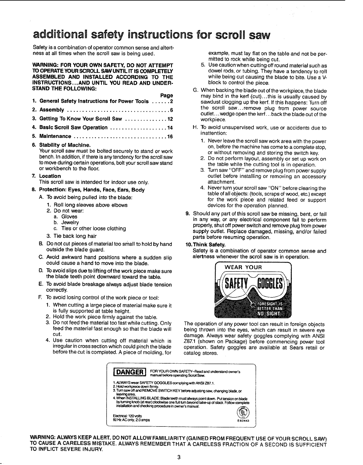
10.Think Safety.
Safety is a combination of operator common sense and
alertness whenever the scroll saw is in operation.
WEAR YOUR
The operation of any power tool can resuit in foreign objects
being thrown into the eyes, which can result in severe eye
damage. Always wear safety goggles complying with ANSI
Z87.1 (shown on Package) before commencing power tool
operation. Safety goggles are available at Sears retail or
catalog stores.
i DANGER ! _o,You_ownSAF_'_-__._ o._.
manu_bek_'eoparat_j Sc_t Saw.
t. ALWAYS wear SAFETY GOGGLES complying with ANSi 7.87.!.
3. Turn saw Off and REMOVE SW]TCH KEY before ad_ saw, ch_ blade, or
_vingarea.
4. When INSTALLING BLADE: Blade teeth must a_ays point down. Put tension on blade
I_ turr_ kno_ (at rear) dook_se or_ _1t _,_rnI_ t_,e,up of _, F_ _
installal_ az_ ct'_YJng: procedure inowner's manual. _\
Eiect_al: 120voWs
60 HZ AC 0_ty, 2,0 amps es,_4_=
I
J
WARNING: ALWAYS KEEP ALERT. DO NOT ALLOW FAMILIARITY (GAINED FROM FREQUENT USE OF YOUR SCROLL SAW)
TO CAUSE A CARELESS MISTAKE. ALWAYS REMEMBER THAT A CARELESS FRACTION OF ASECOND IS SUFFICIENT
TO iNFLICT SEVERE INJURY.
CONNECTING:'I_POWERSUPPLY:OUTLETi....
tf power:cord is worn or Cut, or damaged:in :anyway, have it
:replaced immediately.
WARNING: IF NOT PROPERLY GROUNDED THIS POWER
TOOLCANCAUSEANELECTRICALSHOCKPARTICULARLY
WHEN USED !N DAMP LOCATIONS CLOSE TO PLUMBING.
IF AN ELECTRICAL SHOCK OCCURS THERE iS THE
POTENTIAL OF A SECONDARY HAZARD SUCH AS YOUR
HANDS CONTACTING THE SAW BLADE.
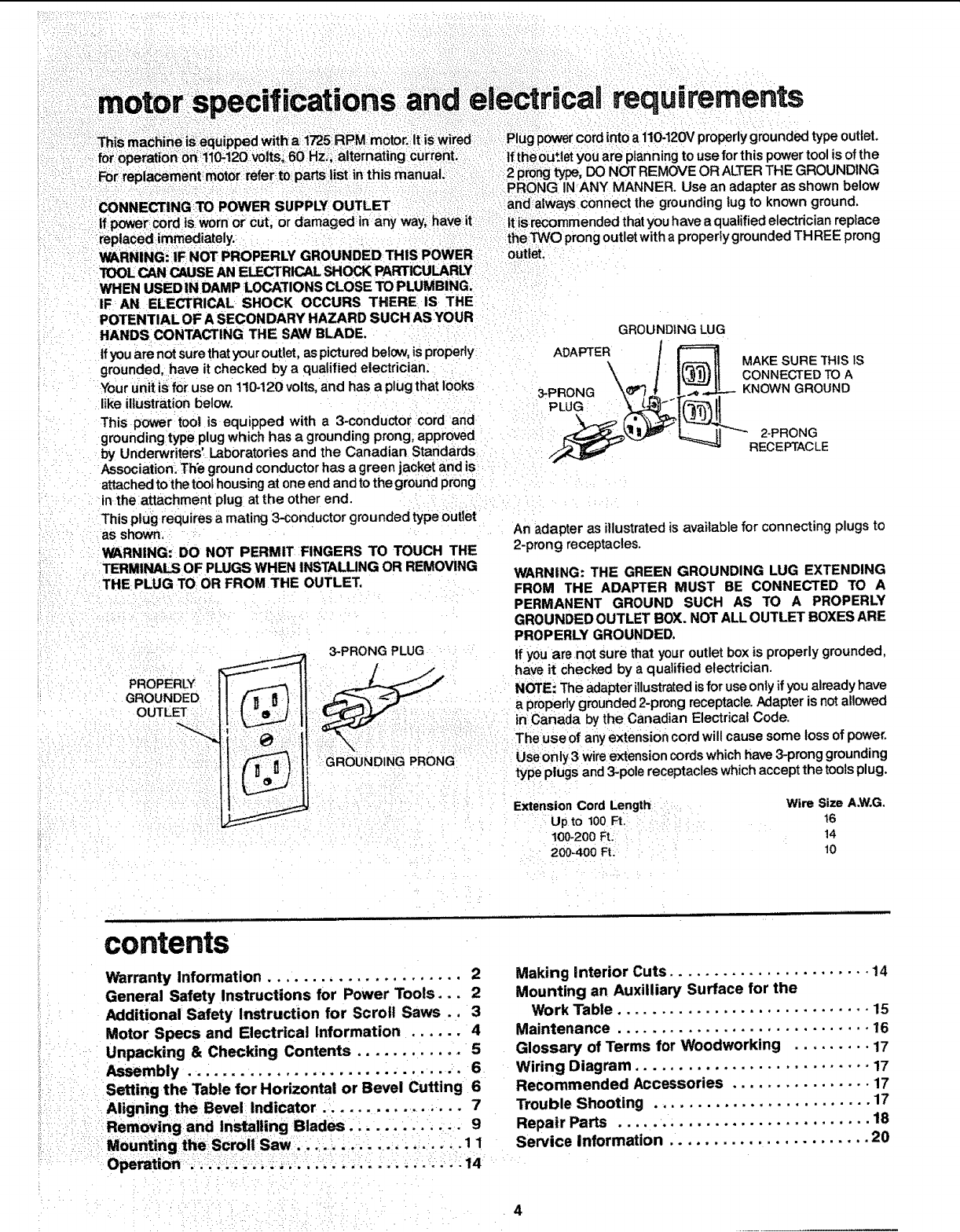
If you are not sure thatyour ouUet, as pictured below, is properly
grounded, have it checked by a qualified electrician.
Your unit is for use on 110-120 volts, and has a plug that looks
like illustration below.
This power tool is equipped with a 3-conductor cord and
grounding type plugwhich has a grounding prong, approved
by Underwriters' Laboratories and the Canadian Standards
Association: Th'e ground conductor has a green jacket and is
attached tothe tool housing at one end and tothe ground prong
inthe attachment plug at the other end.
This plug requires amating 3-conductor grounded type outlet
as shown,
WARNING: DO NOT PERMIT FINGERS TO TOUCH THE
TERMINALS OF PLUGS WHEN INSTALLING OR REMOVING
THE PLUG TO OR FROM THE OUTLET,
PROPER_
GROUNDED
OUTLET
3-PRONG PLUG
GROUNDING PRONG
PRONG INANY MANNER. Use an adapter as shown below
andalways connect the grounding lug to known ground,
it iSrecommended that you have a qualified electrician replace
the TWO prong outlet with a properly grounded THREE prong
outlet:
ADAPTER
3-PRONG
PLUG
GROUNDING LUG
MAKE SURETHIStS
CONNECTED TOA
KNOWN GROUND
2-PRONG
RECE PTAC LE
An adapter as illustrated is available for connecting plugs to
2-prong receptacles.
WARN|NG: THE GREEN GROUNDING LUG EXTENDING
FROM THE ADAPTER MUST BE CONNECTED TO A
PERMANENT GROUND SUCH AS TO A PROPERLY
GROUNDED OUTLET BOX. NOT ALL OUTLET BOXES ARE
PROPERLY GROUNDED.
If you are not sure that your outlet box is properly grounded,
have it checked by a qualified electrician.
NOTE: The adapter illustrated isfor use only if you already have
a properly grounded 2-prong receptacle. Adapter is not allowed
in Canada by the Canadian Electrical Code.
The use of any extension cord will cause some loss of power,
Use only 3 wire extension cords which have 3-prong grounding
type plugs and 3-pole receptacles which accept the tools plug.
Extension Cord Length Wire Size A.W.G.
Up to 100 Ft. 16
100-200 Ft: "14
200-400 Ft. 10
contents
Warranty Information ...................... 2
General Safety Instructions for Power Tools,,. 2
Additional Safety Instruction for Scroll Saws., 3
Motor Specs and Electrical Information ...... 4
Unpacking & Checking Contents ............ 5
Assembly ............... ................ 6
Setting the Table for Horizontal or Bevel Cutting 6
Aligning the Bevel Indicator .................. 7
-:Removing and Installing Blades ........ .. ,. 9
Mounting the! Scroll Saw....:. ....... ,,...... 1 1
Operation ................... ............ 14
Making interior Cuts ....................... 14
Mounting an Auxiiliary Surface for the
Work Table ............................. 15
Maintenance ............................. 16
Glossary of Terms for Woodworking ......... 17
Wiring Diagram ........................... 17
Recommended Accessories ................ 17
Trouble Shooting ......................... 17
Repair Parts ............................. 18
Service information ....................... 20
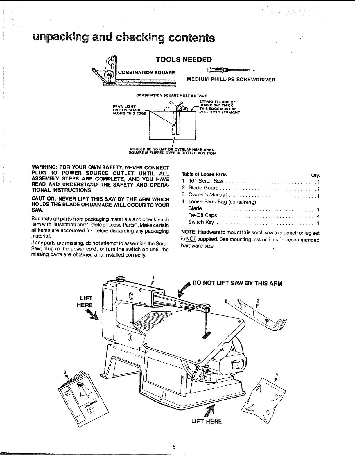
unpacking and checking contents
TOOLS NEEDED
COMBINATION SQUARE
MEDIUM PHILLIPS SCREWDRIVER
COMBINATION SQUARE MUST BE TRUE
STRAtGHT EDGE OF
BOARD 3t4" THICK
DRAW LIGHT EDGE MUST BE
LINE ON BOARD PERFECTLY STRAIGHT
ALONG THiS EDG_
LJ
/,
SHOULD BE NO GAP OR OVERLAP HERE WHEN
SQUARE IS FLIPPED OVER IN DOTTED POSITION
WARNING: FOR YOUR OWN SAFETY, NEVER CONNECT
PLUG TO POWER SOURCE OUTLET UNTIL ALL
ASSEMBLY STEPS ARE COMPLETE, AND YOU HAVE
READ AND UNDERSTAND THE SAFETY AND OPERA-
TIONAL INSTRUCTIONS.
CAUTION: NEVER LIFT THIS SAW BY THE ARM WHICH
HOLDS THE BLADE OR DAMAGE WILL OCCUR TO YOUR
SAW.
Separate all parts from packaging materials and check each
item with illustration and "Table of Loose Parts". Make certain
al! items are accounted for before discarding any packaging
material.
if any parts are r_issing, do not attempt to assemble the Scroll
Saw, plug in the power cord, or turn the switch on until the
missing parts are obtained and installed correctly.
Table of Loose Parts Qty.
t. 16" Scroll Saw ................................ 1
2. Blade Guard .................................. 1
3. Owner's Manual ............................... 1
4. Loose Parts Bag (containing)
Blade ....................................... 1
Re-Oil Caps .................................. 4
Switch Key ................................... 1
NOTE: Hardware to mount this scroll sawto a bench or leg set
is NOT supplied. See mounting instructions for recommended
hardware size.
LIFT
HERE
'N
1
¥
DO NOT LIFT SAW BY THIS ARM
2
¥
3
LIFT HERE
4
II I
5
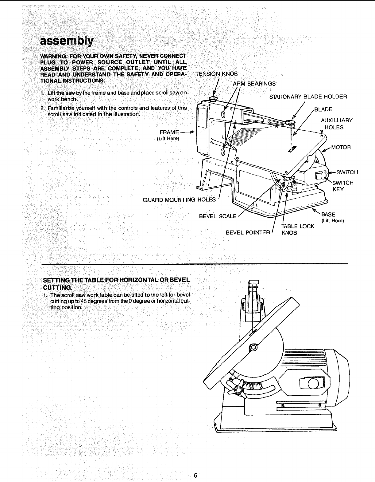
TIONAL INSTRUCTIONS.
the frame and base and place scroll saw on
work:bench:
2. FamiliariZe yourself with the controls and features of this
scroll saw indicated in the il]usVation.
FRAME
(LiftHere)
KNOB
ARM BEARINGS
STATIONARY BLADE HOLDER
/
BLADE
AUXILLIARY
HOLES
GUARD MOUNTING HOLES J
BEVEL SCALE
BEVEL POINTER
TABLE LOCK
KNOB
fITCH
KEY
BASE
(Lift Here)
SETTINGTHETABLE:FOR HORIZONTAL OR BEVEL
CU_ING: ....
1. The scrol! saw work table can be tilted to the leftfor bevel
cutting upto45 degrees from theOdegree orhorizontalcut-
ting position:i:::
/
/
6
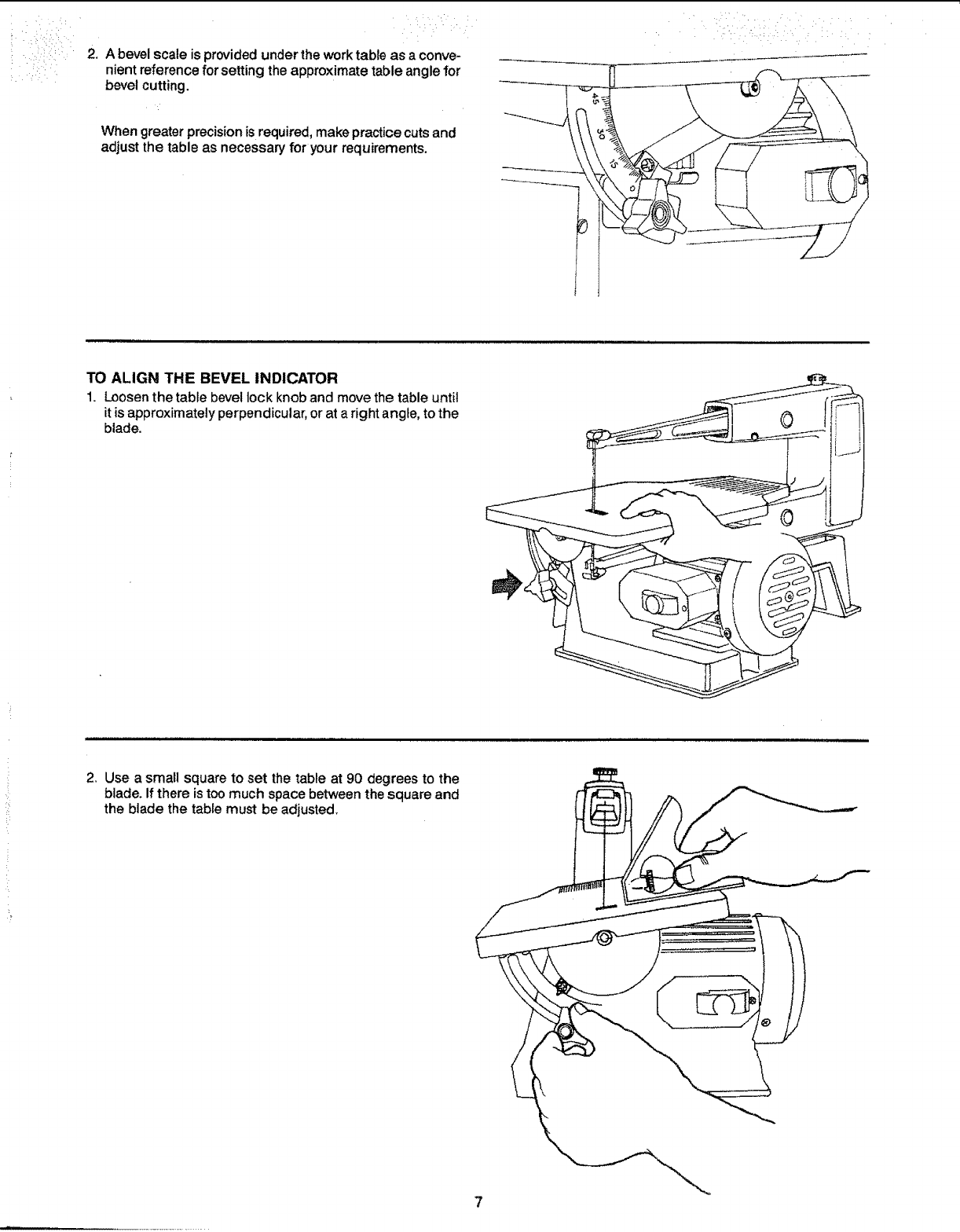
2. A bevel scale is provided under the work table as a conve-
nient reference for setting the approximate table angle for
bevel cutting.
When greater precision is required, make practice cuts and
adjust the table as necessary for your requirements.
• • _••• •i;¸ :•• •• •
TO ALIGN THE BEVEL INDICATOR
1. Loosen the table bevel lock knob and move the table until
it is approximately perpendicular, or at a right angle, to the
blade.
2. Use asmall square to set the table at 90 degrees to the
blade. If there is too much space between the square and
the blade the table must be adjusted.
minil
: =: : The
\/
,J_ i' '
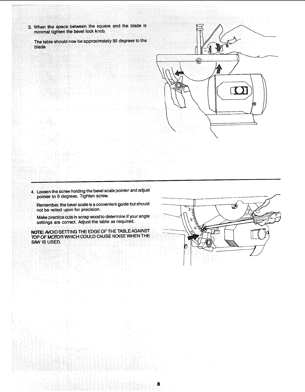
4; Loosen the screw holding the bevel scale pointer and adjust
;pointer to 0 degrees, Tighten screw,
Remember. the bevelscale is a convenientguide butshould
:not be relied upon for precision. _
:Make practic_ecutsin scrap woodto determine if yourangle _-___I\\ _
settings are correct.:AdjuStthe table as required,
TOP OF MOTORWHICH COULD CAUSE NOISE WHEN 3"HE
SAWtSUSED.
:- t I
8

removing and installing bmades
WARNING: TO AVOID INJURY FROM ACCIDENTAL
STARTING, ALWAYS TURN SWITCH "OFF" AND
REMOVE SWITCH KEY BEFORE REMOVING OR
REPLACING THE BLADE.
1_ Loosen tension on blade by turning tension knob counter-
clockwise _ about two full turns.
Slight Pressure Here
2_ Remove blade by pulling forward on blade and then lifting
the blade through the access hole in the table.
Slight downward pressure against the upper arm may be
helpful when removing blade from upper holder.
3, Look at the blade holders closely and notice the blade slots
and pin recesses inthe blade holder. The blade holder is
made so you can position the blade for cutting from the
front or one side of the saw.
Cutting from the side of the sawwilt be necessarywhen your
work piece exceeds !6 inches in length. For zero degree
bevel angle only.
9
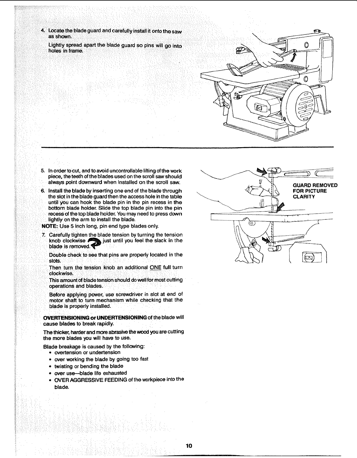
: 4,1_Locate theblade guard and carefully installitonto the saw
ughti_sp_a_a_arttheb_ad_guardsop_nsw,tgo_.to
holes in:frame:.;_
\
E
_i :
5. Inorder to cut, and to avoid uncontrollable liltingof the work
piece, the teeth of the blades used on the scroll sawshould
always point downward when installed on the scroll saw.
6: Install the blade by inserting one end of the blade through
the slot intheblade guard then the access hole inthe table
untilyou can hook the blade pin in the pin recess _nthe
bottom blade holder. Slide the top blade pin into the pin
recesS ofthe top blade holder. Youmay need to press down
lightly on the arm to install the blade
NOTE: Use 5 inch long, pin end type blades only.
7. Carefully tighten the blade tension by turning the tension
knob clockwise _just until you feel the slack in the
blade is removed?T v
Double check to see that pins are properly located in the
slots:
Then turn the tension knob an additional ONE full turn
clockwise.
ThisamoUnt of blade tension should dowelt for mostcutting
operations and blades.
BefOre applying power, use screwdriver in slot at end of
.... motor shaft to turn mechanism while checking that the
....... properly installed.
OVERTENSIONI_NG or UNDERTENSIONING of the blade will
cause blades to break rapidly.
The thicker, harderand more abrasive the woodyou are cutting
the more blades you will have to use.
Blade breakage is caused by the following:
• overtension or undertension
•over working the blade by going too fast
• twisting or bending the blade
•over use-blade life exhausted
•OVER AGGRESSIVE FEEDING of the workpiece intothe
blade.
GUARD REMOVED
FOR PICTURE
CLARITY
•• •_::::•::::::ii_?:i:::•_!:_iii:i::i!:::ii:¸_:':,!:::•i::::::::!.!::::::i:!?_:i::_i:::i_:: lo
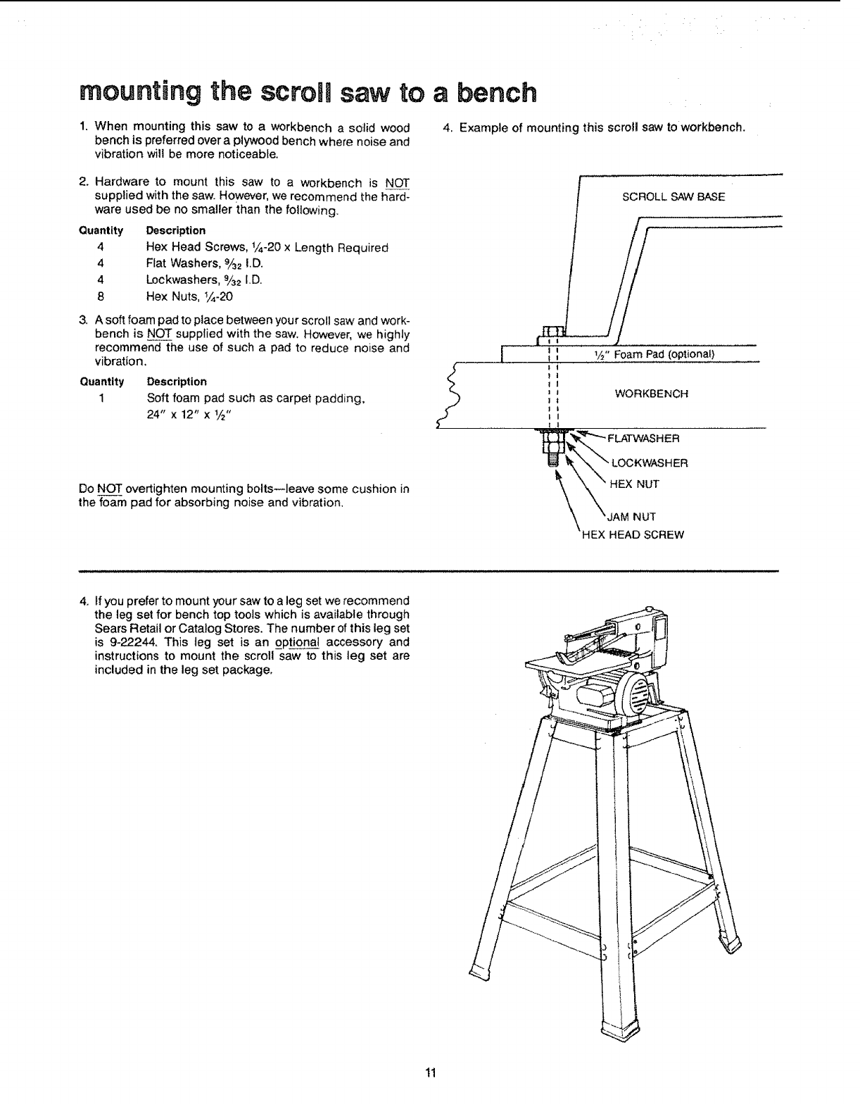
mounting the scroll saw to
1, When mounting this saw to a workbench aso,lid wood
bench is preferred over a plywood bench where noise and
vibration wilt be more noticeable.
2, Hardware to mount this saw to aworkbench is NOT
supplied with the saw. However, we recommend the hard-
ware used be no smaller than the following,
Quantity Description
4 Hex Head Screws, _/_-20x Length Required
4 Flat Washers, %2 I,D.
4 Lockwashers. %2 I.D.
8 Hex Nuts, _/_-20
3, A soft foam pad to place between your scroll saw and work-
bench is NOT supplied with the saw. However, we highly
recommend the use of such a pad to reduce noise and
vibration.
Quantity
1
Description
Soft foam pad such as carpet padding,
24" x 12" x _/_"
abench
4. Example of mounting this scrol! saw to workbench.
SCROLL SAW BASE
!
T_" Foam Pad (optional)
WORKBENCH
Do NOT overtighten mounting bolts--leave some cushion in
the foam pad for absorbing noise and vibration, \LOCKWASHER
HEX NUT
IAM NUT
HEAD SCREW
4, If you prefer to mount your saw to a leg set we recommend
the leg set for bench top tools which is available through
Sears Retail or Catalog Stores. The number of this leg set
is 9-22244, This leg set is an optionat accessory and
instructions to mount the scroll saw to this leg set are
included in the leg set package,
11
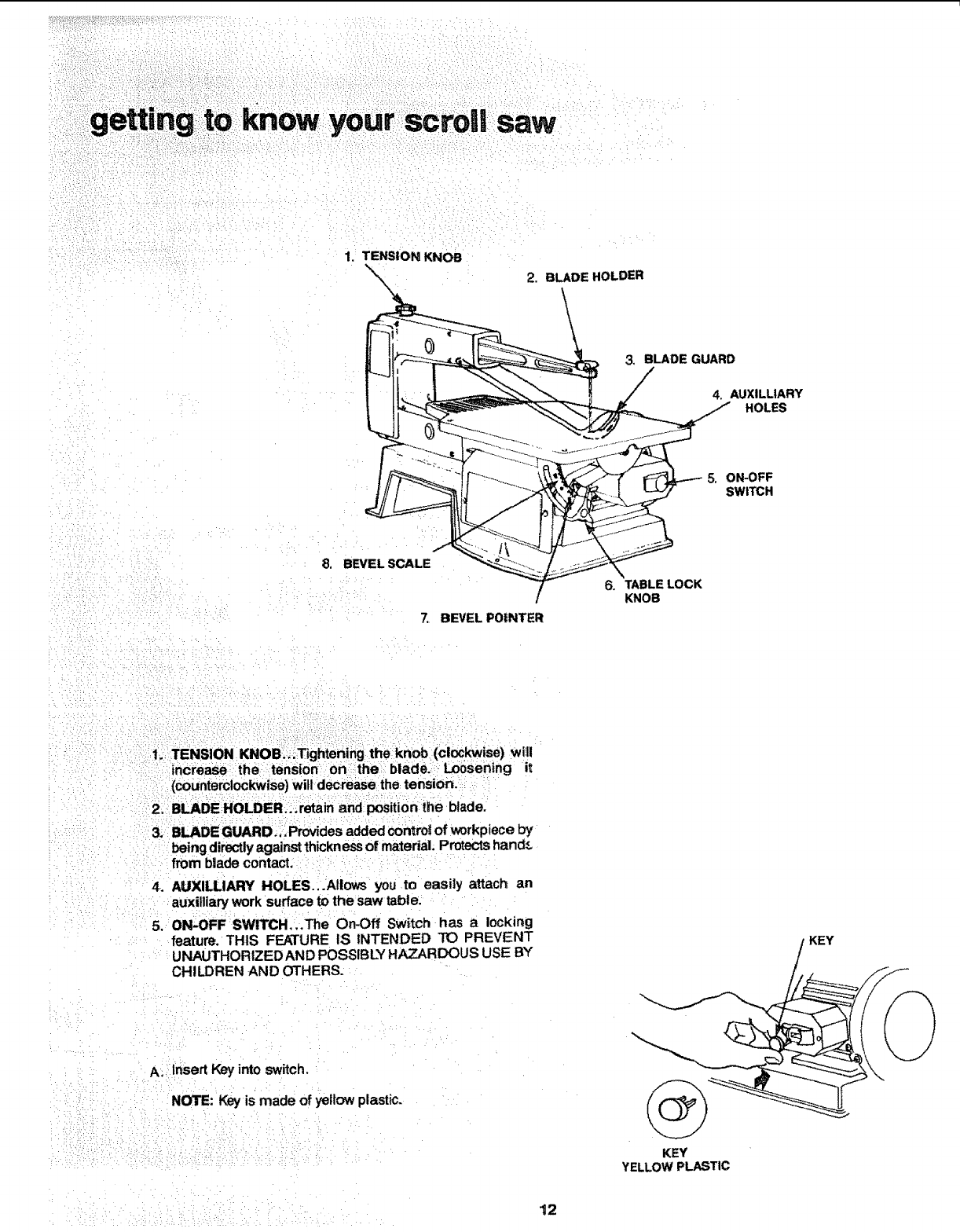
your scrollsaw
i
1. TENSION KNOB
%\\2. BLADE HOLDER
\
3. BLADE GUARD
/
4. AUXILLtARY
HOLES
5, ON-OFF
SWITCH
8. BEVEL SCALE
i
BEVEL PO|NTER
1; TENSION KNOe:;;Tightening the knob(clockwise) will
increase the tension on the blade.-LoOsening it
(counterclockwise) will decrease the tension.
2. BLADE:HOLDER..; retain and position the blade.
3. BLADE GUARD.,.Provides added control of workpiece by
being directly against thickness of material. Protects hand_
from blade contact.
4. AUXILLIARY HOLES...Allows you to easily attach an
auxilliary work surface to the saw table.
5. ON-OFF SWITCH,,.The On-Off Switch has a locking
feature, THIS FEATURE IS INTENDED TO PREVENT
UNAUTHORIZEDAND POSSIBLY HAZARDOUS USE BY
CHILDREN AND OTHERS.
A. Insert Key into switch.
NOTE: Key is made of yellow plastic.
6. TABLE LOCK
KNOB
KEY
KEY
YELLOW PLASTIC
12
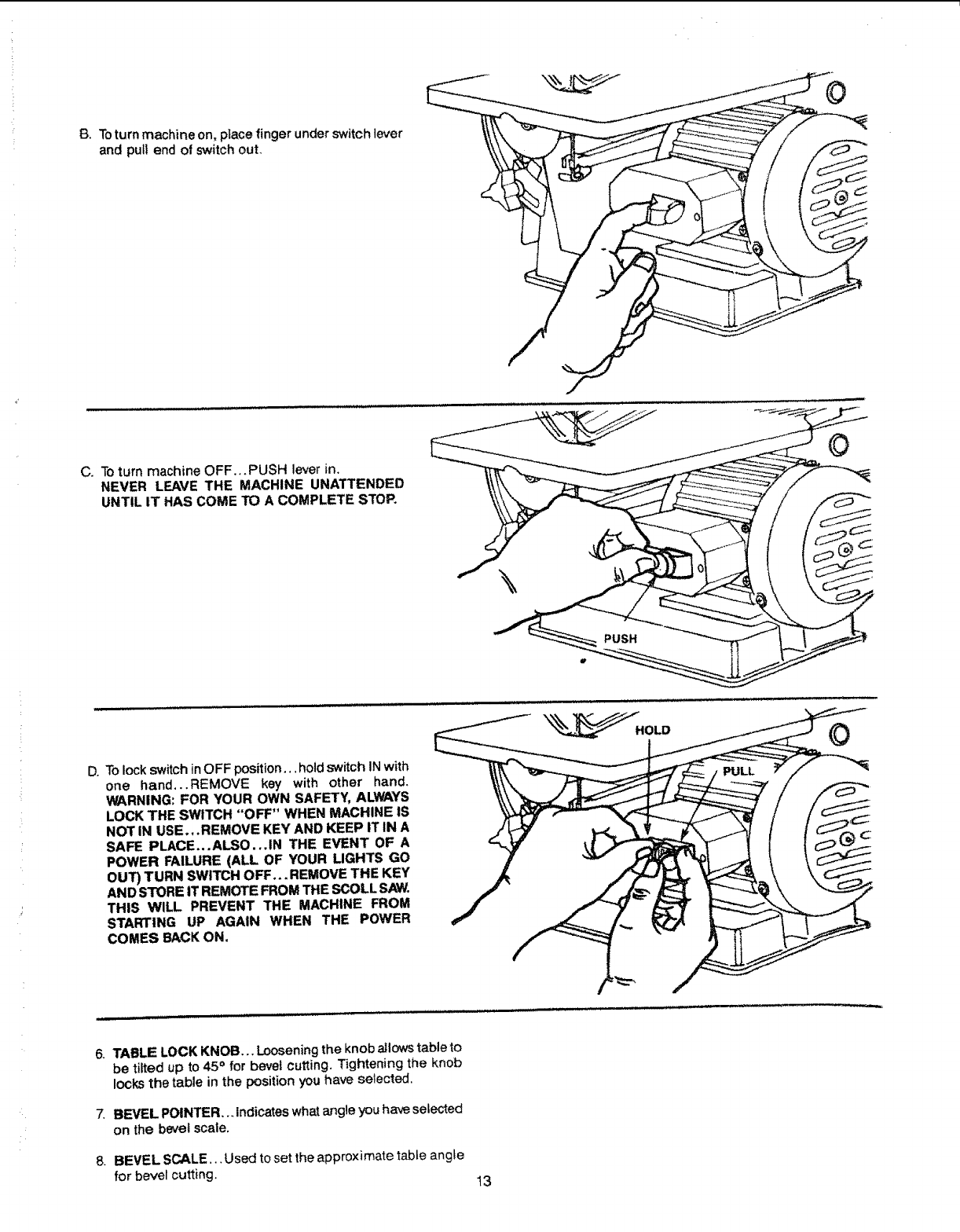
13.Toturnmachineon,place finger under switchlever
and pull end of switch ouL
C. Toturn machine OFF_.PUSH lever in.
NEVER LEAVE THE MACHINE UNATTENDED
UNTIL IT HAS COME TO A COMPLETE STOP,
O
D. Tolock switch inOFF position.., hold switch INwith
one hand,..REMOVE key with other hand.
WARNING: FOR YOUR OWN SAFETY, ALWAYS
LOCK THE SWITCH "OFF" WHEN MACHINE IS
NOT IN USE.,.REMOVE KEY AND KEEP IT IN A
SAFE PLACE...ALSO...IN THE EVENT OF A
POWER FAILURE (ALL OF YOUR LIGHTS GO
OUT) TURN SWITCH OFF... REMOVE THE KEY
AND STORE IT REMOTE FROM THE SCOLL SAW.
THIS WILL PREVENT THE MACHINE FROM
STARTING UP AGAIN WHEN THE POWER
COMES BACK ON,
©
6. TABLE LOCK KNOB,.. Looseningthe knob allows table to
be tilted up to 45° for beret cutting, Tightening the knob
locks the table in the position you have selected.
7. BEVEL POINTER,.. Indicates what angle you have selected
on the bevel scale.
8. BEVEL SCALE... Used to set the approximate table angle
for bevel cutting. 13
you_ scrou: saw before attempting to use the saw.
4; "There is a learning curve for each person whowants to use
this saw. During that period of time itis expected that some
bladeswill break until you learn how to use the saw and
receive the greatest benefit from the blades:
5. Best results are achieved when cutting ,,,_:_1less than one
inch thick.
6. When cutting wood thicker than one inch the user must
guide the wood very, very slowly into the blade and take
extra care not to bend or twist the blade while Cutting in
order to maximize blade life.
7. Teeth on scroll saw blades wear out and as such must be
replaced frequently for best cutting results, Scroll saw
blades generally stay sharp for 1/2 hour to 2 hours of
Cutting.
8. _Toget accurate cuts be prepared to compensate for the
blades' tendency to follow the wood grain as you are
cutting.
9. This scroll saw is intended to cut wood or wood products
only,
10i: When choOsing a blade to use with your scroll saw con-
sider the following carefully.
= Very fine, narrow blades should be used to scroll cut
in thin wood 1/4inch thick or less.
•To cut wood over 1/4inch thick use wider blades.
• Most blade packages state the size or thicknessof wood
which that blade isintended to cut, and the radius, size
of curve, which can be cut with that blade.
•Wider blades can't cut curvesast_ghtor small asthinner
blades.
• Narrower blades work well only on thinner wood
material.
tl.
12.
This saw uses 5 inch long, pin end type blades only. See
your Sears Catalog or Retail Store for accessory blades.
Blades wear faster when cutting p_ywood, which is very
abrasive; when sawing wood which is thicker than the 3/_
inch blade stroke; and when sawing hardwood, or when
side pressure is placed on the blade.
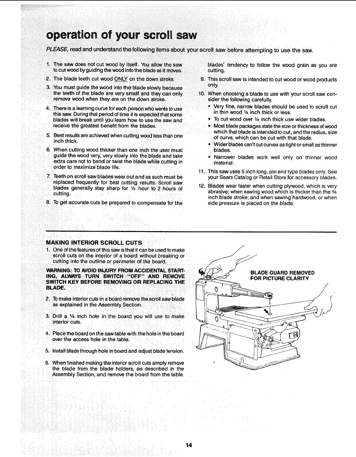
MAKING INTERIOR SCROLL CUTS
1. One ofthe features ofthis saw is that it Can be used to make
scroll cuts on the interior of aboard without breaking or
Cutting into the outline or perimeter of the board.
WARNING: TOAVOID INJURY FROM ACCIDENTAL; START-
IN ...... '_' "
G, ALWAYS TURN SWITCH_ =,OFF ,AND REMOVE
SWITCH KEY BEFORE REMOVING OR REPI,_CING THE
BLADE,
2:T0 make interior cuts in a board remove the Scroll saw blade
as explained in the Assembly Section.
3. Drill a ¼ inch hole in the board you will use to: make
interior cuts.
4._ Place the board on the saw table with the hole inthe board
over the access hole in the table:
5. Install blade throughhole in board and adjust blade tension.
6. When finished making the interiorscroll cuts simply remove
the blade from the blade holders, as described in the
Assembly Section, and remove the board from the table.
/
/
/
BLADE GUARD REMOVED
FOR PICTURE CLARITY
14

MOUNTING AN AUXILLIARY WORK TABLE
1. Fourholes are provided in the work tabte so you can easily
attach an auxiiliary work surface to the saw if your needs
require.
2. Mounting an auxilliary table can allow you to build a Larger
support area to suit your project, and could render a
smoother work surface, as your needs require and an
auxitliary surface can give you more support close to the
blade for special cutting needs tike very small or detailed
projects.
EXAMPLE OF MOUNTING AN AUXILLIARY WORK SURFACE TO THE SAW TABLE
4
-._ FLAT HEAD SCREWS
4 MOUNTING
HOLES tN
TABLE--TYPICAL
COUNTERSINK THE AREA
AROUND EACH HOLE SO
SCREW HEAD WILL NOT
_GET IN YOUR WAYAND
AUX, SURFACEWILL BE SMOOTH
I
"_ ] _'_ OPTIONAL AUX. WORK SURFACE
_'1 TO BE MADE BY SAW USER
! , I
.......1.. I !
__ 4 FLATWASHERS
4LOCKWASHERS
!
_"_ -,_ 4 HEX NUTS
I
%•
II !
ii
II
I I
11
WARNING: TO AVOID TOOL TIPPING OR SUPPORT
FAILURE, AUXILLIARY WORK SURFACE SHOULD NOT
EXCEED 24" x 12" x_/_"
At least an 1/4inch hole will be needed in the auxi!liary surface
to insert blades.
DRILL the hole for the blade first. Then MARK location of other
holes.
HARDWARE--not supplied--recommended to
auxitliary surface to saw worktable.
Quantity Description
4 Flat Head Screws #8*32 x 1
4 Fiat Washers #8
4 Lockwashers #8
4 He× Nuts #8-32
mount
15
SWITCH
FROM POWER
OR LUBRI-
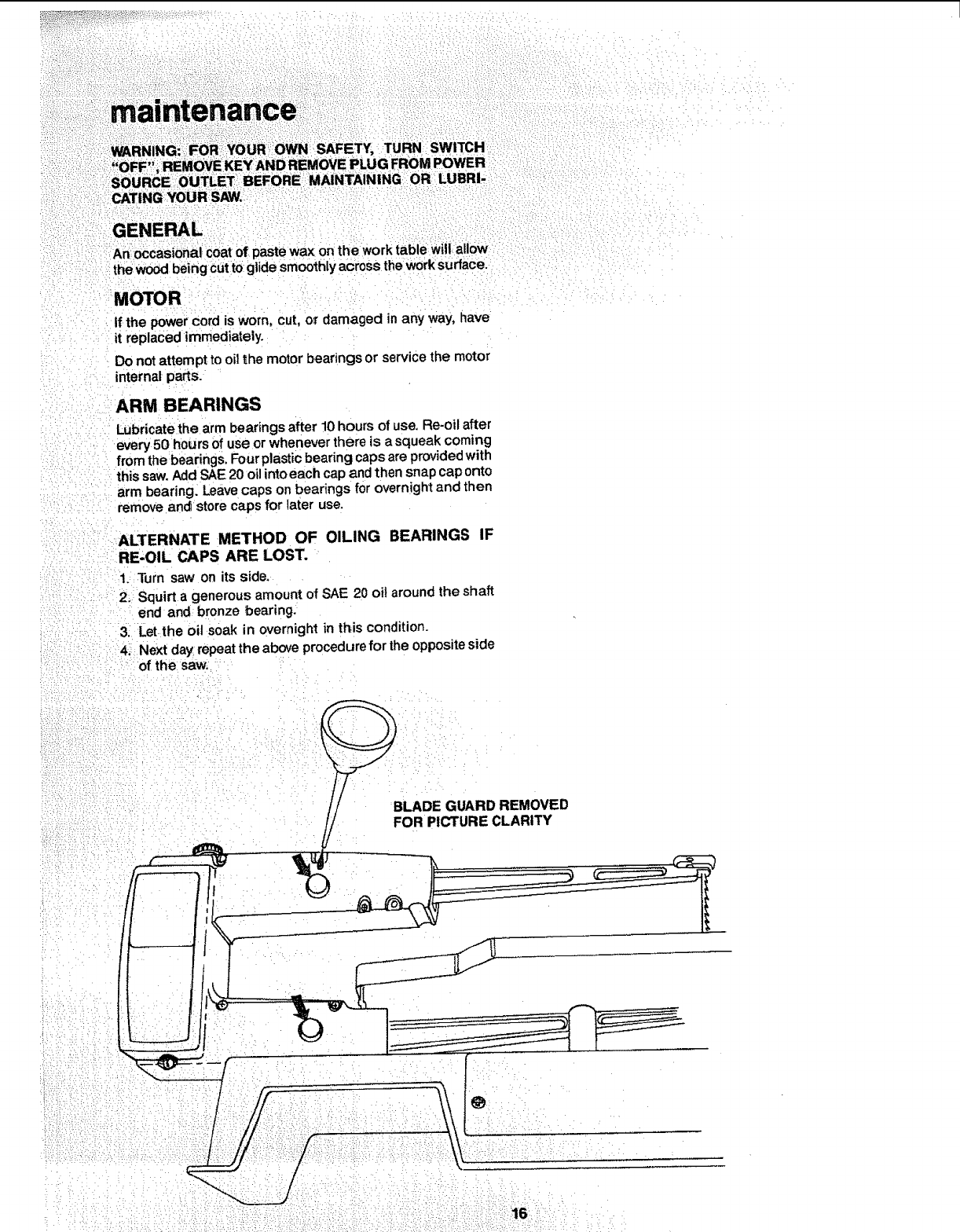
An occasional coat of paste wax on the work table will:allow
the wood being CuttOglide smoothly across the work surface.
MOTOR
if the power cord is worn, cut, o_ damaged in any way, have
it replaced immediately.
Do not attempt to oil the motor bearings or service the motor
internal parts.
ARM BEARINGS
Lubricate the arm bearings after 10 hours of use. Re-oil after
every 50 hours of use or whenever there is asqueak coming
from the bearings. Four plastic bearing caps are provided with
this saw. Add SAE 20 oil into each cap and then snap cap onto
arm bearing. Leave caps on bearings for overnight and then
remove an_ store caps for later use.
ALTERNATE METHOD OF OILING BEARINGS IF
RE,OIL CAPS ARE LOST.
I. Turn saw on its side.
2. Squirt a generous amount of SAE 20 oil around the shaft
end and bronze bearing.
3. Let the oil soak in overnight in this condition.
4, Next day repeat the above procedure for the opposite side
of the saw.
BLADE GUARD REMOVED
FOR PICTURE CLARITY
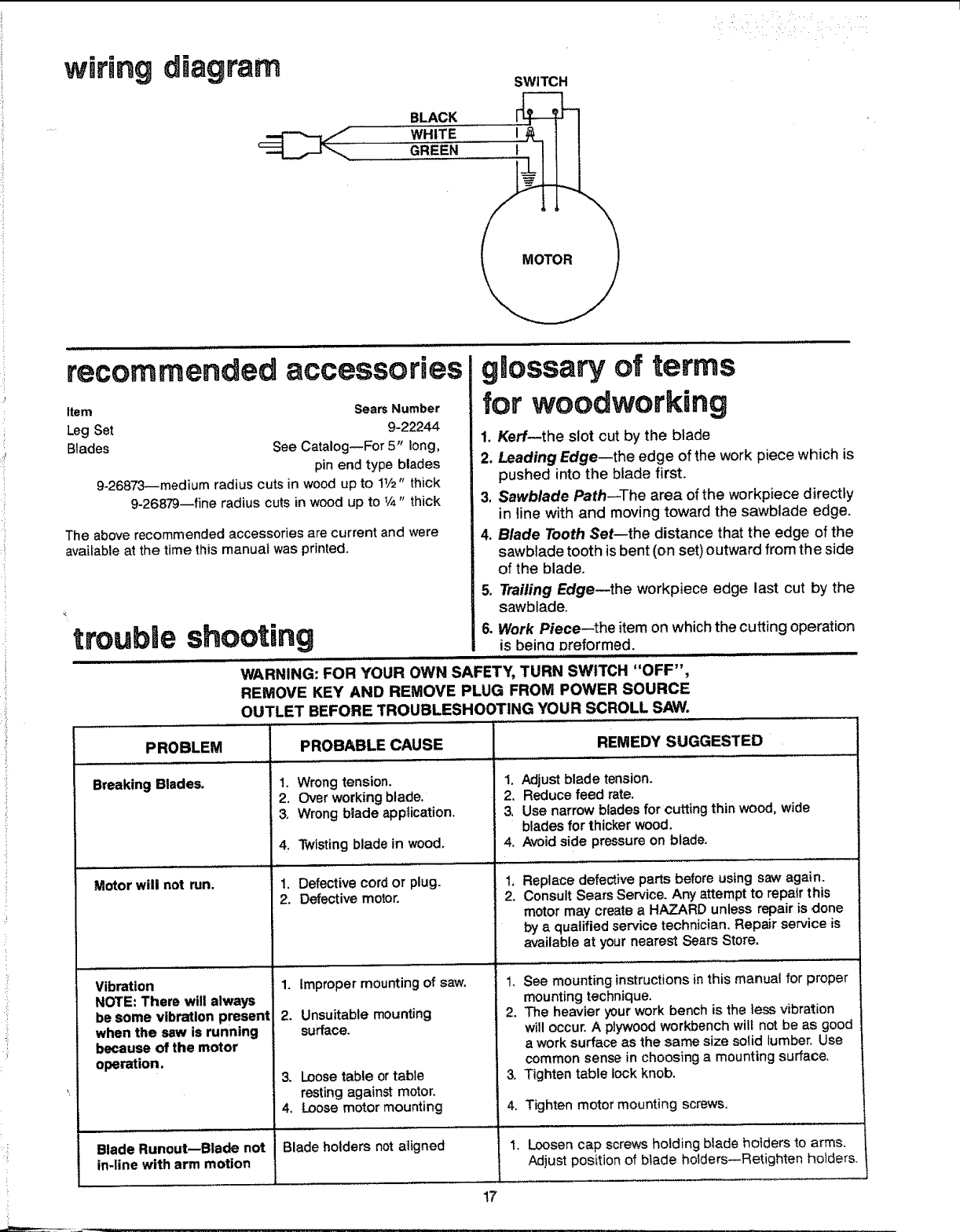
diagram
BLACK
wHITE ....
GREEN: ....
SWITCH
,,
recommended accessories
Item Sears Number
Leg Set 9-22244
Blades See Catalog--For 5" long,
pin end type blades
9-26873--medium radius cuts in wood up to 11/2" thick
9-26879--fine radius cuts in wood up to 1/4" thick
The above recommended accessories are current and were
available at the time this manual was printed.
glossary of terms
for woodworking
1. Kerf--the slot cut by the blade
2, Leading Edge--the edge of the work piece which is
pushed into the blade first.
3, Sawblade Path--The area of the workpiece directly
in line with and moving toward the sawblade edge.
4. Blade Tooth Set--the distance that the edge of the
sawblade tooth is bent (on set) outward from the side
of the blade.
=
6.
Trailing Edge--the workpiece edge last cut by the
sawblade.
trouble shooting Work Piece--the item on which the cutting operation
is beina preformed.
WARNING: FOR YOUR OWN SAFETY, TURN SWITCH "OFF",
REMOVE KEY AND REMOVE PLUG FROM POWER SOURCE
OUTLET BEFORE TROUBLESHOOTING YOUR SCROLL SAW.
PROBLEM PROBABLE CAUSE REMEDY SUGGESTED
Breaking Blades.
Motor will not run.
Vibration
NOTE: There will always
be some vibration present
when the saw is running
because of the motor
operation.
1. Wrong tension.
2. Over working blade.
3. Wrong blade application.
4. Twisting blade in wood,
1. Defective cord or plug.
2. Defective motor.
.....,, ,,,,,
1. improper mounting of saw.
2. Unsuitable mounting
surface.
3. Loose table or table
resting against motor.
4, Loose motor mounting
Blade Runout--Blade not Blade holders not aligned
in-line with arm motion
1, Adjust blade tension.
2. Reduce feed rate.
3, Use narrow blades for cutting thin wood, wide
blades for thicker wood.
4. Avoid side pressure on blade.
1,
2.
1,
2,
.
4.
1.
Replace defective parts before using saw again.
Consult Sears Service, Any attempt to repair this
motor may create a HAZARD unless repair is done
by a qualified service technician. Repair service is
available at your nearest Sears Store.
See mounting instructions in this manual for proper
mounting technique.
The heavier your work bench is the less vibration
will occur, A plywood workbench will not be as good
a work surface as the same size solid lumber. Use
common sense in choosing a mounting surface,
Tighten table lock knob.
Tighten motor mounting screws,
Loosen cap screws holding blade hoiders to arms.
Adjust position of blade holders--Retighten holders.
17

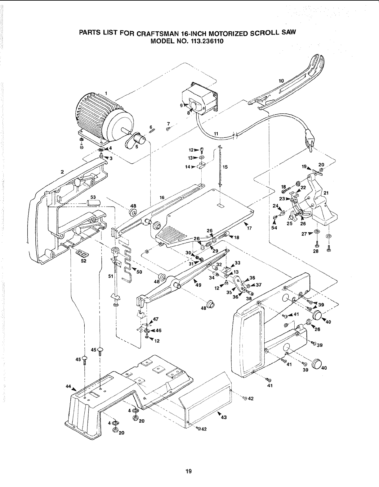
PAroS LIST FOR CRAFTSMAN 16-iNCH MOTORIZED SCROLL SAW
":++•.......... MODEL NO. 1;13.2 36110
Always: order by Part Nurn bet---Not
..... by Key Number
:::Key¸¸
:No; i
:=: I++' 66055 ,+Motor(includes Switch & Cord) i
166066 HousingAsm; (includesKey No.48)
;_3iSTD 522507 *Hex, Head Screw 1t4-20 x 314
41STD 55i125 *Lockwasher 1/4
5 66047 " Coupling, Eccentric
6STD 503103 *Screw, Set 5/16-18 x 5116
7 STD 510602 *Screw Pan Cross 6-32 x 1/4
8 " 60256 "Key Switch i
9 62442 Switch, Locking ....
i 0 66049 Guard Blade
iii 66056 Cord With Plug
;12 66070 *Screw, I-{ex, Soc. Cap #8-32 x
:t 3t8 ....
• +
*Lockwasher, External No. 8
Holder, Upper Blade
:tBlade
:::,++16::.: LArm+ upper
Table
+Screw, He:< Soc. Cap 114-20 x
:I 1-518 1
! 9 66058 SPring, Anti-Rattle
STD54!025 *Nut, Rex 1/4 x20
Support Table
22: .66044 Bracket, Tilt
! *ScreWi Pan: Cross Type"T _':10-32
Key
NO.
28 STD 523107
29 66063
30 193250
31 66069
32 66060
33 66051
34 66045
35 66054
36 STD 551110
37 STD 541110
38 60116
39 66071
40 66046
41 66072
42 STD 51t 103
43 66057
44 66040
45 STD 532510
46 STD 55! 108
47 66059
48 i66041
49 66068
66061
52 66062
53 :66043
66048
Part
No. Description
| i
Screw, Hex Hd. 5/16 -!8 x 7/8
Spring, Compression
*Screw, Hex Soc. Cap 10-32 x 7/8
Washer
Spacer, Bearing
Holder, Lower Blade
Bushing
Link Arm
*Lockwasher No. 10
*Nut Hex t0-32
*Screw, Hex Soc. Cap 10-32 x 3/4
*Screw, Pan Cross Type "T" 8-32
x 1-1/8
Cap, Re-Oil
*Screw, Pan Cross Type "T" 8-32
x1-318
*Screw Pan Cross 10-32 x 3/8
Plate, Cover
Base
*Bolt, Carriage 114" x 20 x 1
*Lockwasher No. 8
Retainer
Bearing, Flanged
Arm, Lower
Spring
Knob Asm. Tension
Retainer, Bolt
Bumper
Owners Manual (not illustrated)
*Screw Pan Cross 1!4-20 x 112
*Standardhardwareitems--may be purchasedlocally.
1" Stock Item--May be secured through the Hardware Dept.
of most Sears Retail Stores or Catatooj Order Houses.
18
PARTS LIST FOR CRAFTSMAN 16-INCH MOTORIZED SCROLL SAW
MODEL NO, 113,236!10
53
52
\, 48
26
13
36
35 3E
i"
39
4_20
19
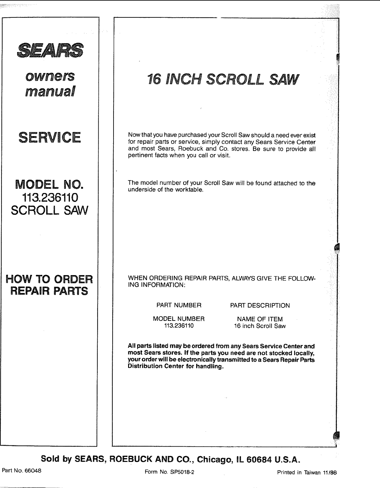
RVlCE
MODEL NO.
113.236110
SCROLL SAW
HOW TO ORDER
REPAIR PARTS
16 INCH SCROLL
Now that you have purchased your Scroll Saw should a need ever exist
for repair parts or service, simply contact any Sears Service Center
and most Sears, Roebuck and Co. stores. Be sure to provide all
pertinent facts when you call or visit.
The model number of your Scroll Saw will be found attached to the
underside of the worktable.
WHEN ORDERING REPAIR PARTS, ALWAYS GIVE THE FOLLOW-
ING INFORMATION:
PART NUMBER
MODEL NUMBER
113.236110
PART DESCRIPTION
NAME OF ITEM
16 inch Scroll Saw
All parts listed may be ordered from any Sears Service Center and
most Sears stores, if the parts you need are not stocked locally,
your order will be electronically transmitted to a Sears Repair Parts
Distribution Center for handling.
!
_i_i__I
Sold by SEARS, ROEBUCK AND CO., Chicago, IL 60684 U.S.A.
Part No. 66048 Form No. SP5018-2 Printed in Taiwan 11186
