Sears 113 2945 Users Manual
11329450 11329450 CRAFTSMAN CRAFTSMAN 10 IN. RADIAL ARM SAW - Manuals and Guides L0810016 View the owners manual for your CRAFTSMAN CRAFTSMAN 10 IN. RADIAL ARM SAW #11329450. Home:Tool Parts:Craftsman Parts:Craftsman CRAFTSMAN 10 IN. RADIAL ARM SAW Manual
CRAFTSMAN Saw Radial Manual L0810016 CRAFTSMAN Saw Radial Owner's Manual, CRAFTSMAN Saw Radial installation guides
113.2945 to the manual dd58eec4-68df-4b6b-865d-097b073163b4
2015-02-05
: Sears Sears-113-2945-Users-Manual-399425 sears-113-2945-users-manual-399425 sears pdf
Open the PDF directly: View PDF ![]() .
.
Page Count: 28

Sears owners manual
MODEL No.
113.29450
CAUTION:
Read Safety
Rules and
Instructions
Carefully
•Assembly
• Operating
• Repair Parts
CRArT MR"/
SAFETY RULES FOR POWER TOOLS
I. KNOW YOUR POWER TOOL
Read the owner's manual carefully. Learn its applica-
tion and limitations as well as the specific potential
hazards peculiar to this tool.
2. GROUND ALL TOOLS
If tool is equipped with three-prong plug, it should be
plugged into a three-hole receptacle. If adapter is used
to accommodate two-prong receptacle, the adapter wire
must be attached to a known ground. Never remove
third prong.
3. KEEP GUARDS IN PLACE
and in working order.
4. REMOVE ADJUSTING KEYS AND
WRENCHES
Form habit of checking to see that keys and adjusting
wrenches are removed from tool before turning on tool.
5. KEEP WORK AREA CLEAN
Cluttered areas and benches invite accidents.
6. AVOID DANGEROUS ENVIRONMENT
Don't use power tools in damp or wet locations. Keep
work area well illuminated.
7. KEEP CHILDREN AWAY
All visitors should be kept a safe distance from work
area.
8. MAKE WORKSHOP KID PROOF
--with padlocks, master switches, or by removing
starter keys.
9. DON'T FORCE TOOL
It will do the job better and be safer at the rate for
which it was designed.
I0. USE RIGHT TOOL
Don't force tool or attachment to do ajob it was not
designed for.
11.
12.
13.
WEAR PROPER APPAREL
No loose clothing or jewelry to get caught in moving
parts.
USE SAFETY GLASSES
Also use face or dust mask if cutting operation is dusty.
SECURE WORK
Use clamps or a vise to hold work when practical. It's
safer than using your hand, frees both hands to oper-
ate tool.
14. DON'T OVERREACH
Keep your proper footing and balance at all times.
15. MAINTAIN TOOLS IN TOP
CONDITION
Keep tools sharp and clean for best and safest per-
formance. Follow instructions for lubricating and
changing accessories.
16. DISCONNECT TOOLS
before servicing and when changing accessories such
as blades, bits, cutters.
17.
18.
AVOID ACCIDENTAL STARTING
Make sure switch is "OFF" before plugging in cord.
USE RECOMMENDED ACCESSORIES
Consult the owner°s manual. Use of improper acces-
sories may be hazardous.
WEAR YOUR
Copyright 1969 by Power Tool Institute, Inc. All rights reserved.
The operation of any power tool can result in foreign objects
being thrown into the eyes, which can result in severe eye
damage. Always wear safety glasses or eye shields before
commencing power tool operation. We recommend Wide
Vision Safety Mask for use over spectacles, or standard safety
glasses.., available at Sears retail or catalog stores.
THIS SAFETY SEAL OF THE
POWER TOOL INSTITUTE ASSURES YOU...
1. That the manufacturer's power tools, including the particular tool
associated with the Seal, are produced in accordance with applicable
Standards For Safety of Underwriters' Laboratories and American
National Standards (ANSI).
2. That compliance with applicable safety standards is assured by in-
dependent inspection and testing conducted by Underwriters" Labora-
tories (UL).
3. That every motorized tool is inspected under power.
4. That every tool has with it adequate instructions and a list of safety
rules for the protection of the user.
5. That the tool manufacturer is a member of the Power Tool Institute and
is a sponsor of the Institute's Consumer Safety Education Program.
ASSEMBLING AND ADJUSTING YOUR SAW
2
Figure 1
10 9
1
4
S
7
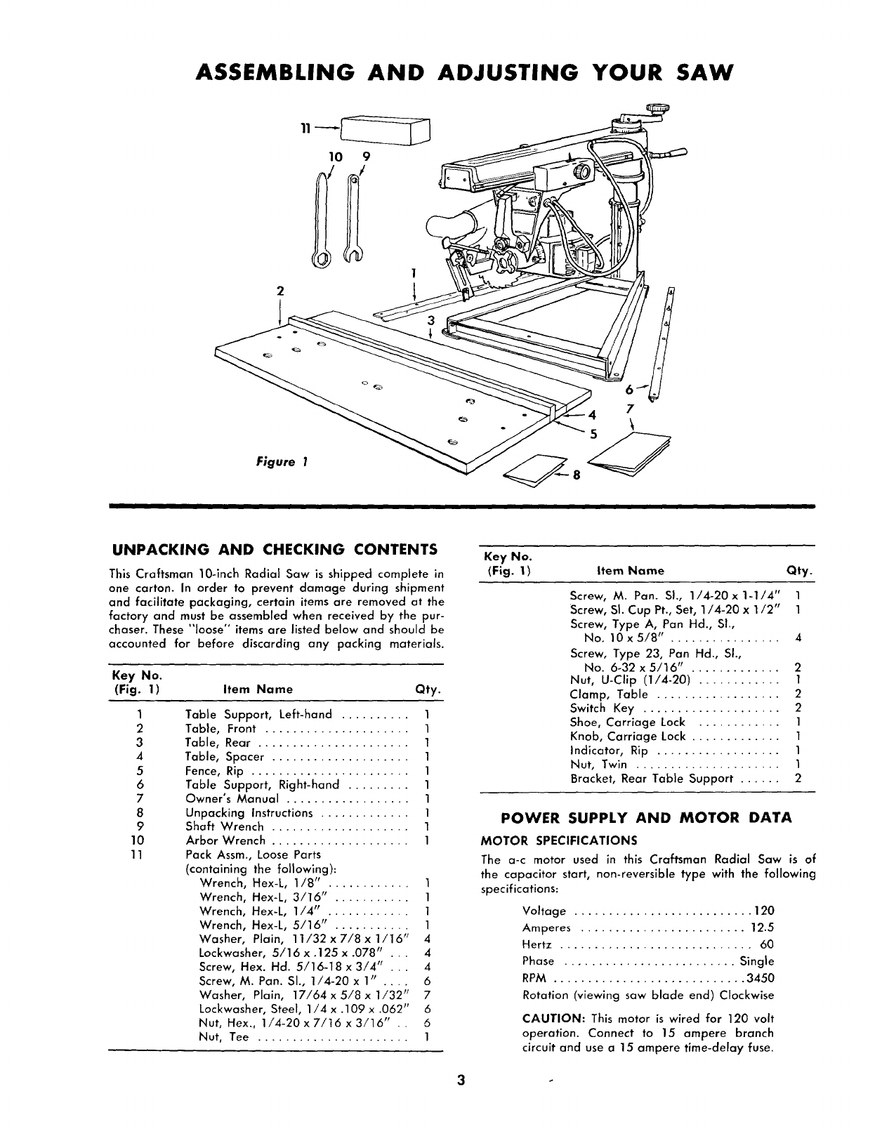
UNPACKING AND CHECKING CONTENTS
This Craftsman 10olnch Radial Saw is shipped complete in
one carton. In order to prevent damage during shipment
and facilitate packaging, certain items are removed at the
factory and must be assembled when received by the pur-
chaser. These "loose" items are listed below and should be
accounted for before discarding any packing materials.
Key No.
(Fig. 1) Item Name Qty.
1
2
3
4
5
6
7
8
9
10
11
Table Support, Left-hand .......... 1
Table, Front ..................... 1
Table, Rear ...................... 1
Table, Spacer .................... 1
Fence, Rip ....................... 1
Table Support, Right-hand ......... 1
Owner's Manual .................. 1
Unpacking Instructions ............. 1
Shaft Wrench .................... 1
Arbor Wrench .................... 1
Pack Assm., Loose Parts
(containing the following):
Wrench, Hex-L, 1/8" ............ 1
Wrench, Hex-L, 3/16" ........... 1
Wrench, Hex-L, 1/4" ............ 1
Wrench, Hex-L, 5/16" ........... 1
Washer, Plain, 11/32 x 7/8 x1/16 _/ 4
Lockwasher, 5/16x.125 x.078" . . . 4
Screw, Hex. Hd. 5/16-18 x 3/4 'I ... 4
Screw, M. Pan. SI., 1/4-20 x 1" .... 6
Washer, Plain, 17/64 x 5/8 x 1/32 p_ 7
Lockwasher, Steel, 1/4 x .109 x .062" 6
Nut, Hex., 1/4-20x7/16 x 3/16" .. 6
Nut, Tee ...................... 1
Key No.
(Fig. 1) Item Name Qty.
Screw, M. Pan. SI., 1/4-20x1-1/4" 1
Screw, SI. Cup Pt., Set, 1/4-20 x1/2" 1
Screw, Type A, Pan Hd., Sl.,
No. 10x5/8" ................ 4
Screw, Type 23, Pan Hd., Sl.,
No. 6-32 x 5/16" ............. 2
Nut, U-Clip (1/4-20) ............ 1
Clamp, Table .................. 2
Switch Key .................... 2
Shoe, Carriage Lock ............ 1
Knob, Carriage Lock ............. 1
Indicator, Rip .................. 1
Nut, Twin ..................... 1
Bracket, Rear Table Support ...... 2
POWER SUPPLY AND MOTOR DATA
MOTOR SPECIFICATIONS
The a-c motor used in this Craftsman Radial Saw is of
the capacitor start, non-reversible type with the following
specifications:
Voltage .......................... 120
Amperes ........................ 12.5
Hertz ............................ 60
Phase ......................... Single
RPM ............................ 3450
Rotation (viewing saw blade end) Clockwise
CAUTION: This motor is wired for 120 volt
operation. Connect to 15 ampere branch
circuit and use a 15 ampere time-delay fuse.
3
MOTOR SAFETY PROTECTION
The saw motor is equipped with amanual-reset thermal
overload protector, designed to open the power line circuit
when the motor temperature exceeds a safe value.
1. If the protector opens the line and stops the saw motor,
press the saw switch to the "OFF" position immediately
and allow the motor to cool.
2. After cooling to a safe operating temperature, the
overload protector can be closed manually by pushing
in the red button on the motor cover and nameplate. If
the red button will not snap into place immediately, the
motor is still too hot and must be allowed to cool for a
while longer. (An audible click will indicate protector
is closed.)
3. As soon as the red button will snap into running position,
the saw may be started and operated normally by
pressing the saw switch to the "ON" position.
4. Frequent opening of fuses or circuit breakers may result
if motor is overloaded, or if the motor circuit is fused
with a fuse other than those recommended. Do not use
a fuse of greater capacity without consulting the power
company.
5. Although the motor is designed for operation on the
voltage and frequency specified on motor nameplate,
normal loads will be handled safely on voltages not more
than 10% above or below the nameplate voltage. Heavy
loads, however, require that voltage at motor terminals
be not less than the voltage specified on nameplate.
6. Most motor troubles may be traced to loose or incorrect
connections, overloading, reduced input voltage (which
results when small size wires are used in the supply
circuit) or when the supply circuit is extremely long.
Always check connections, load and supply circuit when
the motor fails to perform satisfactorily. Check wire
sizes and lengths with the table in the next paragraph.
IMPORTANT: The following wire sizes are
recommended for connecting the motor to
power source for trouble-free operation.
Length of Wire Size Required
Conductor (American Wlre Gauge No.)
50 feet or less ................. No. 12
100 feet or less ................. No. 10
100 feet to 150 feet ............. No. 8
150 feet to 200 feet ............. No. 6
200 feet to 400 feet ............. No. 4
For circuits of greater length the wire size must be in-
creased proportionally.
MOUNTING THE SAW ON A WORK BENCH
The saw should be placed on a suitable sturdy work bench,
or Craftsman Power Tool Bench. The base of the saw must
be mounted flush to a flat surface on the work bench to
prevent distortion of the saw base. The nuts, screws, and
washers which attach the wooden shipping skids to the
saw base may be used to secure the saw base to the work
bench, or tool bench.
ALIGNMENT INSTRUCTIONS
NOTE: The seven basic "steps" that follow are
essential in order to insure correct saw table
alignment.
WARNING: Make sure the power cord is
not plugged into an electrical outlet when
working on the saw.
STEP ONE--INSTALLATION AND ADJUSTMENT
OF TABLE SUPPORTS
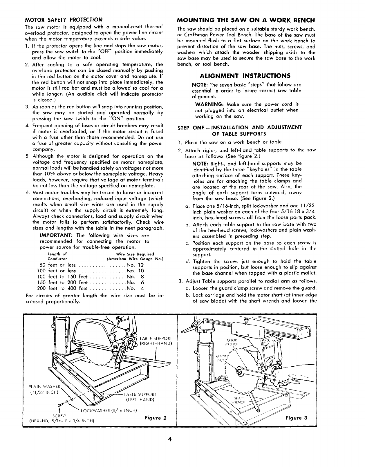
1. Place the saw on a work bench or table.
2. Attach right-, and left-hand table supports to the saw
base as follows: (See figure "2.)
NOTE: Right-, and left-hand supports may be
identified by the three "keyholes" in the table
attaching surface of each support. These key-
holes are for attaching the table clamps and
are located at the rear of the saw. Also, the
angle of each support turns outward, away
from the saw base. (See figure 2.)
a. Place one 5/16-inch, split Iockwasher and one 11/32-
inch plain washer on each of the four 5/16-18 x 3/4-
inch, hex-head screws, all from the loose parts pack.
b. Attach each table support to the saw base with two
of the hex-head screws, Iockwashers and plain wash-
ers assembled in preceding step.
c. Position each support on the base so each screw is
approximately centered in the slotted hole in the
support.
d. Tighten the screws just enough to hold the table
supports in position, but loose enough to slip against
the base channel when tapped with a plastic mallet.
3. Adjust Table supports parallel to radial arm as follows:
a. Loosen the guard clamp screw and remove the guard.
b. Lock carriage and hold the motor shaft (at inner edge
of saw blade) with the shaft wrench and loosen the
ITABLE SUPPORT
(RIGHT-HAND)
PLAIN WASHER\ J
(11/32 INCH) _L'_ _--TABLE SUPPORT
_._ "'_ (LEFT-HAND)
_ LOCKWASHER (5/16 INCH)
SCREW Figure 2
(HEX-HD, 5/16-1_ _ 3/4 INCH)
ARBOR
WRENCH
SHAFT
Figure 3
SAW BLADE
ARBOR
// AR OR
zJ NUT
SHAFT WRENCH
SWIVEL
INDEX
\ BEVEL KNOB
COLLAR COLLAR LOCK
(OUTER) (INNER) KNOB Figure 4
ELEVATION CRANK
ARM
HANDLE
TABLE
(LEFT-HAND)
ARM LOCK
HANDLE
TABLE SUPPORT
(RIGHT-HAND)
Figure 5
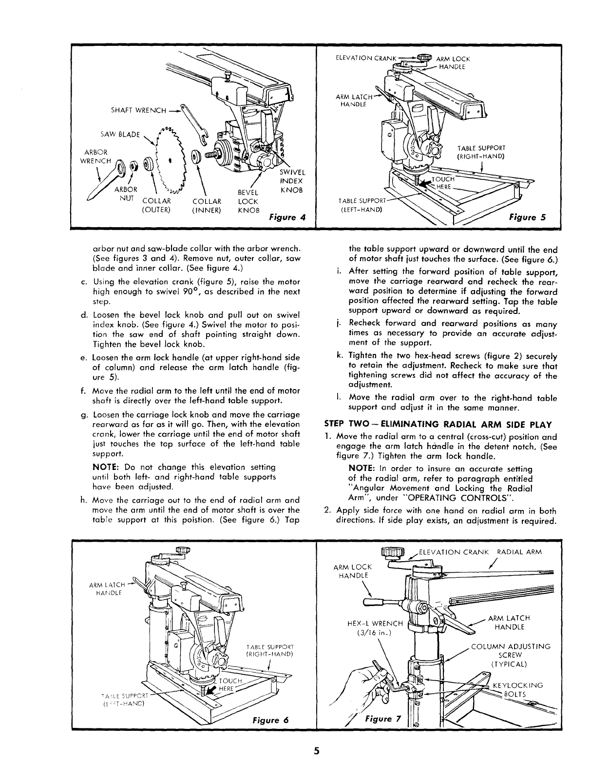
arbor nut and saw-blade collar with the arbor wrench.
(See figures 3 and 4). Remove nut, outer collar, saw
blade and inner collar. (See figure 4.)
c. Using the elevation crank (figure 5), raise the motor
high enough to swivel 90 ° , as described in the next
step.
d. Loosen the bevel lock knob and pull out on swivel
index knob. (See figure 4.) Swivel the motor to posi-
tion the saw end of shaft pointing straight down.
Tighten the bevel lock knob.
e. Loosen the arm lock handle (at upper right-hand side
of column) and release the arm latch handle (fig-
ure 5).
f. Move the radial arm to the left until the end of motor
shaft is directly over the left-hand table support.
g. Loosen the carriage lock knob and move the carriage
rearward as far as it will go. Then, with the elevation
crank, lower the carriage until the end of motor shaft
just touches the top surface of the left-hand table
support.
NOTE: Do not change this elevation setting
until both left- and right-hand table supports
have been adjusted.
h. Move the carriage out to the end of radial arm and
move the arm until the end of motor shaft is over the
table support at this poistion. (See figure 6.) Tap
the table support upward or downward until the end
of motor shaft just touches the surface. (See figure 6.)
i. After setting the forward position of table support,
move the carriage rearward and recheck the rear-
ward position to determine if adjusting the forward
position affected the rearward setting. Tap the table
support upward or downward as required.
j. Recheck forward and rearward positions as many
times as necessary to provide an accurate adjust-
ment of the support.
k. Tighten the two hex-head screws (figure 2) securely
to retain the adjustment. Recheck to make sure that
tightening screws did not affect the accuracy of the
adjustment.
I. Move the radial arm over to the right-hand table
support and adjust it in the same manner.
STEP TWO--ELIMINATING RADIAL ARM SIDE PLAY
1. Move the radial arm to acentral (cross-cut) position and
engage the arm latch hc_ndle in the detent notch. (See
figure 7.) Tighten the arm lock handle.
NOTE: In order to insure an accurate setting
of the radial arm, refer to paragraph entitled
"Angular Movement and Locking the Radial
Arm", under "OPERATING CONTROLS".
2. Apply side force with one hand on radial arm in both
directions. If side play exists, an adjustment is required.
ii
ARM LATCH "_"% / _'_ \
HANDLE
(RIGHT-HAND)
< _ ° rOUCH
TA _LE SUPPORT
([ :::T-HAND)
Figure 6
i
ARM LOCK
HANDLE
\
Figure 7
CRANK RADIAL ARM
/
ARM LATCH
HANDLE
COLUMN ADJUSTING
SCREW
(TYPICAL)
P
KEYLOCKING
BOLTS
BOTTOM SIDE OF TABLE
T-NUT CORRECTLY INSTALLED
LEVELING SCRTW TOP OF TABLE
BASE
T-NUT
LEVELING SCREW INSTALLED
IN T-NUT
Figure 8
FRONT
TABLE
REAR TABLE
SUPPORT BRACKET
Q,I
SCREW
(No. 10 x 5/8 IN.)
COLUMN
SUPPORT
FRONT TABLE
HOLE FOR TABLE
HOLD-DOWN SCREW
(SEVEN,TOTAL)
R.H. TABLE SUPPORT
LEVELING SCREW
HOLE Figure 9
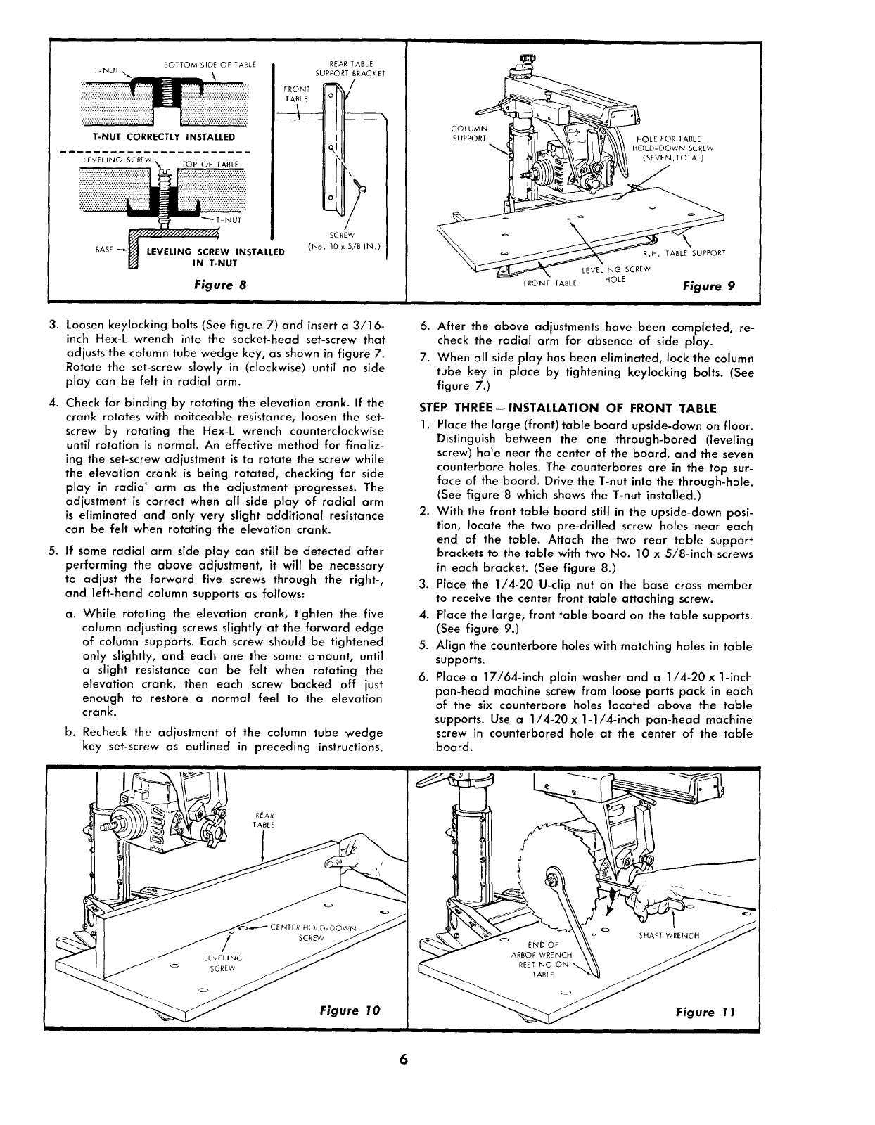
3. Loosen keylocking bolts (See figure 7) and inserta 3/16-
inch Hex-L wrench into the socket-head set-screw that
adjusts the column tube wedge key, as shown in figure 7.
Rotate the set-screw slowly in (clockwise) until no side
play can be felt in radial arm.
4. Check for binding by rotating the elevation crank. If the
crank rotates with noitceable resistance, loosen the set-
screw by rotating the Hex-L wrench counterclockwise
until rotation is normal. An effective method for finaliz-
ing the set-screw adjustment is to rotate the screw while
the elevation crank is being rotated, checking for side
play in radial arm as the adjustment progresses. The
adjustment is correct when all side play of radial arm
is eliminated and only very slight additional resistance
can be felt when rotating the elevation crank.
5. If some radial arm side play can still be detected after
performing the above adjustment, it will be necessary
to adjust the forward five screws through the right-,
and left-hand column supports as follows:
a. While rotating the elevation crank, tighten the five
column adjusting screws slightly at the forward edge
of column supports. Each screw should be tightened
only slightly, and each one the same amount, until
aslight resistance can be felt when rotating the
elevation crank, then each screw backed off just
enough to restore a normal feel to the elevation
crank.
b. Recheck the adjustment of the column tube wedge
key set-screw as outlined in preceding instructions.
Figure 10
ii
6. After the above adjustments have been completed, re-
check the radial arm for absence of side play.
7. When all side play has been eliminated, lock the column
tube key in place by tightening keylocking bolts. (See
figure 7.)
STEP THREE--INSTALLATION OF FRONT TABLE
1. Place the large (front) table board upside-down on floor.
Distinguish between the one through-bored (leveling
screw) hole near the center of the board, and the seven
counterbore holes. The counterbores are in the top sur-
face of the board. Drive the T-nut into the through-hole.
(See figure 8 which shows the T-nut installed.)
2. With the front table board still in the upside-down posi-
tion, locate the two pre-drilled screw holes near each
end of the table. Attach the two rear table support
brackets to the table with two No. 10 x 5/8-inch screws
in each bracket. (See figure 8.)
3. Place the 1/4-20 U-clip nut on the base cross member
to receive the center front table attaching screw.
4. Place the large, front table board on the table supports.
(See figure 9.)
5. Align the counterbore holes with matching holes in table
supports.
6. Place a 17/64-inch plain washer and a 1/4-20 x 1-inch
pan-head machine screw from loose parts pack in each
of the six counterbore holes located above the table
supports. Use a 1/4-20 x 1-1/4-inch pan-head machine
screw in counterbored hole at the center of the table
board.
Figure 1 1
7. Start the leveling screw into the T-nut on front table, but
do not allow the tip of the screw to protrude beyond the
bottom surface of front table.
8. Install Iockwashers and nuts on the six screws in the
table supports and tighten them finger tight. Start the
pan-head screw in the counterbored hole near the
center of front board into the U-nut on saw base, but
leave it approximately two turns loose.
9. At this time the front table should be checked and ad-
justed at the center position as follows:
a. Move carriage to maximum rear position.
b. Using one edge of the rear table board as a straight-
edge, lay the board on the front table as shown
in figure 10.
c. Sight between edge of rear table and surface of front
table, to determine if the front table is low or high
at the center position. If front table is high, tighten
the center hold-down screw until it is level, then rotate
the leveling screw clockwise until it is "snug" against
the base front member. If the table is low at the
center, loosen the hold-down screw and rotate the
leveling screw clockwise until the front table is level,
then tighten the hold-down screw.
NOTE: After tightening screws, as described
above, always recheck to make sure that the
front table remains level. In some cases, a final
"touch-up" adjustment may be required.
STEP FOUR--SQUARING THE CROSS-CUT TRAVEL
1. Loosen the bevel lock knob, pull out on swivel index
knob and swivel the motor until the swivel index knob
indexes the motor with the shaft in a horizontal (zero)
position. Tighten the bevel lock knob.
2. Check to make sure the arm latch handle is securely
latched in the detent an_l the arm lock handle is still tight.
3. Install the saw blade as follows:
a. Place the inner collar on motor shaft. (See figure 4.)
b. Slide saw blade on motor shaft. Make sure teeth are
pointed in direction of saw rotation. (See figure 42
c. Install outer collar and arbor nut.
NOTE: The arbor shaft has left-hand threads.
d. Use the shaft wrench on motor shaft and arbor wrench
on arbor nut to tighten the nut, as shown in figure 11.
e. Lower the saw blade (with elevation crank) until the
blade isapproximately 1/32 inch above table surface.
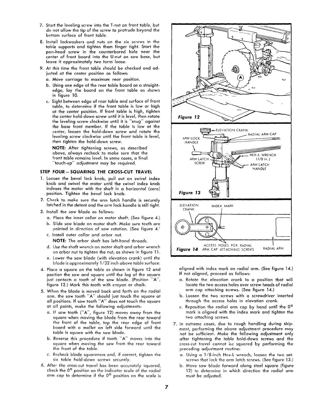
4. Place a square on the table as shown in figure 12 and
position the saw and square until the leg of the square
just contacts a tooth of the saw blade. (Position "A °',
figure 12.) Mark this tooth with crayon or chalk.
5. When the blade is moved back and forth on the radial
arm, the saw tooth "A '° should just touch the square at
all positions. If saw tooth "A" does not touch the square
at oil points, make the following adjustments:
a. If saw tooth ("A", figure 12) moves away from the
square when moving the blade from the rear toward
the front of the table, tap the rear edge of front
board with a mallet on left side forward until the
table is square with the saw blade.
b. Reverse this procedure if tooth "A" moves into the
square when moving the saw from the rear toward
the front of the table.
c. Recheck blade squareness and, if correct, tighten the
six table hold-dawn screws securely.
6. After the crass-cut travel has been accurately squared,
check the 0° position on the indicator scale of the radial
arm cap to determine if the 0 ° position on the scale is
Figure 12 _ _ -
i
J_]_.-,,_- ELE V AT IO N CRANK
ARM LO _ -- _ j RADIAL ARM CAP
CK i "_
HANDLE _ _
l_ HANDLE
Figure 13 _ ! _
ELEVATION INDEX MARK
ACCESS HOLES FOR RADIAL
Fjgure 14 ARM CAP AIi"ACHING SCREWS
,L
RADIAL ARM
aligned with index mark on radial arm. (See figure 14.)
If not aligned, proceed as follows:
a. Rotate the elevation crank to a position that will
locate the two access holes over screw heads of radial
arm cap attaching screws. (See figure 14.)
b. Loosen the two screws with a screwdriver inserted
through the access holes in elevation crank.
c. Reposition the radial arm cap by hand until the 0 °
mark is aligned with the index mark and tighten the
two attaching screws.
7. In extreme cases, due to rough handling during ship-
ment, performing the above adjustment procedure may
not be sufficient. Make the following adjustment only
after tightening the table hold-down screws and the
cross-cut travel cannot be squared by performing the
preceding adjustment routine:
a. Using a 1/8-inch Hex-L wrench, loosen the two set-
screws that lock the arm latch screws. (See figure 13.)
b. Move saw blade forward along steel square (figure
12) to determine in which direction the radial arm
must be adjusted.
7
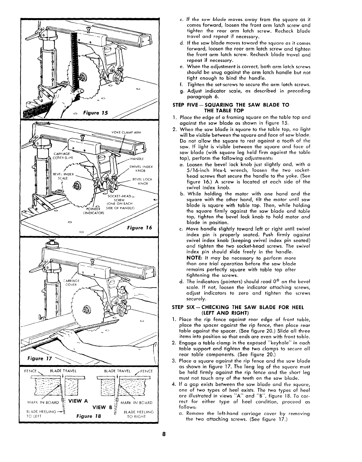
Figure 15
Figure 16
Figure 17
• I
FENCE,,,,,.,, BLADE TRAVEL BLADE TRAVEL //FENCE
BLADE.E EL,.O --ti VIEW Bill MARr._LADE,NHEEL,NGBOARD
To C[FT Figure 18 TO RIOHT
II
f.
g.
STEP
1.
2.
c. If the saw blade moves away from the square as it
comes forward, loosen the front arm latch screw and
tighten the rear arm latch screw. Recheck blade
travel and repeat if necessary.
d. If the saw blade moves toward the square as it comes
forward, loosen the rear arm latch screw and tighten
the front arm latch screw. Recheck blade travel and
repeat if necessary.
e. When the adjustment is correct, both arm latch screws
should be snug against the arm latch handle but not
tight enough to bind the handle.
Tighten the set-screws to secure the arm latch screws.
Adjust indicator scale, as described in preceding
paragraph 6.
FIVE--SQUARING THE SAW BLADE TO
THE TABLE TOP
Place the edge of a framing square on the table top and
against the saw blade as shown in figure 15.
When the saw blade is square to the table top, no light
will be visible between the square and face of saw blade.
Do not allow the square to rest against a tooth of the
saw. If light is visible between the square and face of
saw blade (with square leg held firm against the table
top), perform the following adjustments:
a. Loosen the bevel lock knob just slightly and, with a
5/16-inch Hex-L wrench, loosen the two socket-
head screws that secure the handle to the yoke. (See
figure 16.) A screw is located at each side of the
swivel index knob.
b. While holding the motor with one hand and the
square with the other hand, tilt the motor until saw
blade is square with table top. Then, while holding
the square firmly against the saw blade and table
top, tighten the bevel lock knob to hold motor and
blade in position.
c. Move handle slightly toward left or right until swivel
index pin is properly seated. Push firmly against
swivel index knob (keeping swivel index pin seated)
and tighten the two socket-head screws. The swivel
index pin should slide freely in the handle.
NOTE: It may be necessary to perform more
than one trial operation before the saw blade
remains perfectly square with table top after
tightening the screws.
d. The indicators (pointers) should read 0 ° on the bevel
scale. If not, loosen the indicator attaching screws,
adjust indicators to zero and tighten the screws
securely.
STEP SIX--CHECKING THE SAW BLADE FOR HEEL
(LEFT AND RIGHT)
1. Place the rip fence against rear edge of front table,
place the spacer against the rip fence, then place rear
table against the spacer. (See figure 20.) Slide all three
items into position so that ends are even with front table.
2. Engage a table clamp in the exposed "'keyhole" in each
table support and tighten the two clamps to secure all
rear table components. (See figure 20.)
3. Place a square against the rip fence and the saw blade
as shown in figure 17. The long leg of the square must
be held firmly against the rip fence and the short leg
must not touch any of the teeth on the saw blade.
4. If a gap exists between the saw blade and the square,
one of two types of heel exists. The two types of heel
are illustrated in views "A" and "B", figure 18. To cor-
rect for either type of heel condition, proceed as
follows:
a. Remove the left-hand carriage cover by removing
the two attaching screws. (See figure 17.)
8
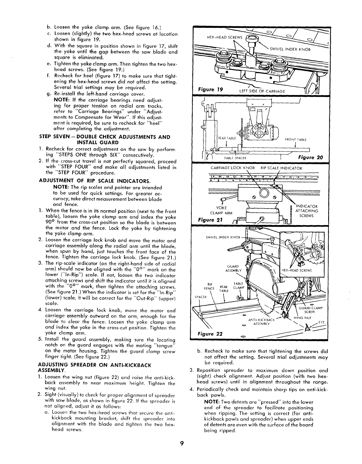
b. Loosen the yoke clamp arm. (See figure 16.1
c. Loosen (slightly) the two hex-head screws at location
shown in figure 19.
d. With the square in position shown in figure 17, shift
the yoke until the gap between the saw blade and
square is eliminated.
e. Tighten the yoke clamp arm. Then tighten the two hex-
head screws. (See figure 19.)
f. Recheck for heel (figure 17) to make sure that tight-
ening the hex-head screws did not affect the setting.
Several trial settings may be required.
g. Re-install the left-hand carriage cover.
NOTE: If the carriage bearings need adjust-
ing for proper tension on radial arm tracks,
refer to "Carriage Bearings °' under "Adjust°
ments to Compensate for Wear". If this adjust-
ment is required, be sure to recheck for "heel"
after completing the adjustment.
STEP SEVEN- DOUBLE CHECK ADJUSTMENTS AND
INSTALL GUARD
1. Recheck for correct adjustment on the saw by perform-
ing "STEPS ONE through SIX" consecutively.
2. If the cross-cut travel is not perfectly squared, proceed
with "STEP FOUR" and make all adjustments listed in
the "STEP FOUR" procedure.
ADJUSTMENT OF RIP SCALE INDICATORS.
NOTE: The rip scales and pointer are intended
to be used for quick settings. For greater ac-
curacy, take direct measurement between blade
and fence.
1. When the fence is in its normal position (next to the front
table), loosen the yoke clamp arm and index the yoke
90 ° from the cross-cut position so the blade is between
the mator and the fence. Lock the yoke by tightening
the yoke clamp arm.
2. Loosen the carriage lock knob and move the motor and
carriage assembly along the radial arm until the blade,
when spun by hand, just touches the front face of the
fence. Tighten the carriage lock knob. (See figure 21.)
3. The rip-scale indicator (on the right-hand side of radial
arm) should now be aligned with the "0 °'' mark on the
lower ("In-Rip") scale. If not, loosen the two indicator
attaching screws and shift the indicator until it is aligned
with the "0 °'° mark, then tighten the attaching screws.
(See figure 21 .) When the indicator is set for the "In-Rip °'
(lower) scale, it will be correct for the "Out-Rip" (upper/
scale.
4. Loosen the carriage lock knob, move the motor and
carriage assembly outward on the arm, enough for the
blade to clear the fence. Loosen the yoke clamp arm
and index the yoke in the cross-cut position. Tighten the
yoke clamp arm.
5. Install the guard assembly, making sure the locating
notch on the guard engages with the mating "tongue"
on the motor housing. Tighten the guard clamp screw
finger tight. (See figure 22.)
ADJUSTING SPREADER ON ANTI-KICKBACK
ASSEMBLY.
1. Loosen the wing nut (figure 22) and raise the anti-kick-
back assembly to near maximum height. Tighten the
wing nut.
2. Sight (visually) to check for proper alignment of spreader
with saw blade, as shown in figure 22. If the spreader is
not aligned, adjust it as follows:
a. Loosen the two hex-head screws that secure the anti-
kickback mounting bracket, shift the spreader into
alignment with the blade and tighten the two hex-
head screws.
i i
HEX_HEAD__
Figure /
E
_k:d " I
.TABLESPACER Figure 20
CARRIAGE LOCK KNOB RIP SCALE INDICATOR
• Z
÷"' It" '''_ ''''_''_' ' "_' ' "I_"' -i"_ g__ _._
_/_INDICATOR
YOKE __ :_ ATTACHING
CLAMPARMI- _-, SCREWS
Figure 21 __//________
- i).-J /
Figure 22 _=_ _ _
b. Recheck to make sure that tightening the screws did
not affect the setting. Several trial adjustments may
be required.
3. Reposition spreader to maximum down position and
(sight) check alignment. Adjust position (with two hex-
head screws) until in alignment throughout the range.
4. Periodically check and maintain sharp tips on anti-kick-
back pawls.
NOTE: Two de|ents are "pressed" into the lower
end of the spreader to facilitate positioning
when ripping. The setting is correct (for anti-
kickback pawls and spreader) when upper ends
of detents are even with the surface of the board
being ripped.
9
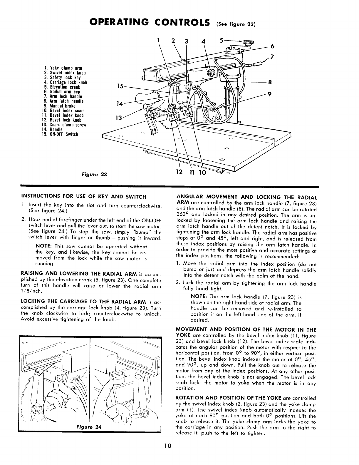
OPERATING CONTROLS (See figure 23)
1. Yoke clamp arm
2. Swivel index knob
3. Safety lock key
4. Carriage lock knob
5. Elevation crank
6. Radial arm cap
7. Arm lock handle
8. Arm latch handle
9. Manual brake
10. Bevel index scale
11. Bevel index knob
12. Bevel lock knob
13. Guard clamp screw
14. Handle
15. ON-OFFSwitch
12
Figure 23
3
12
45-----_i_ 6
INSTRUCTIONS FOR USE OF KEY AND SWITCH
1. Insert the key into the slot and turn counterclockwise.
(See figure 24.)
2. Hook end of forefinger under the left end of the ON-OFF
switch lever and pull the lever out, to start the saw motor.
(See figure 24.) To stop the saw, simply _'bump °" the
switch lever with finger or thumb--pushing it inward.
NOTE: This saw cannot be operated without
the key, and likewise, the key cannot be re-
moved from the lock while the saw motor is
running.
RAISING AND LOWERING THE RADIAL ARM is accom-
plished by the elevation crank (5, figure 23). One complete
turn of this handle will raise or lower the radial arm
1/8-inch.
LOCKING THE CARRIAGE TO THE RADIAL ARM is ac-
complished by the carriage lock knob (4, figure 23). Turn
the knob clockwise to lock; counterclockwise to unlock.
Avoid excessive tightening of the knob.
ANGULAR MOVEMENT AND LOCKING THE RADIAL
ARM are controlled by the arm lock handle (7, figure 23)
and the arm latch handle (8). The radial arm can be rotated
360 ° and locked in any desired position. The arm is un-
locked by loosening the arm lock handle and raising the
arm latch handle out of the detent notch. It is locked by
tightening the arm lock handle. The radial arm has positive
stops at 0 ° and 45 °, left and right, and is released from
these index positions by raising the arm latch handle. In
order to provide the most positive and accurate settings at
the index positions, the following is recommended:
1. Move the radial arm into the index position (do not
bump or jar) and depress the arm latch handle solidly
into the detent notch with the palm of the hand.
2. Lock the radial arm by tightening the arm lock handle
fully hand tight.
NOTE: The arm lock handle (7, figure 23) is
shown on the right-hand side of radial arm. The
handle can be removed and re-installed to
position it on the left-hand side of the arm, if
desired.
MOVEMENT AND POSITION OF THE MOTOR IN THE
YOKE are controlled by the bevel index knob (11, figure
23) and bevel lock knob (12). The bevel index scale indi-
cates the angular position of the motor with respect to the
horizontal position, from 0 ° to 90 °, in either vertical posi-
tion. The bevel index knob indexes the motor at 0 °, 45 ° ,
and 90 ° , up and down. Pull the knob out to release the
motor from any of the index positions. At any other posi-
tion, the bevel index knob is not engaged. The bevel lock
knob locks the motor to yoke when the motor is in any
position.
ROTATION AND POSITION OF THE YOKE are controlled
by the swivel index knob (2, figure 23) and the yoke clamp
arm (1). The swivel index knob automatically indexes the
yoke at each 90 ° position and both 0 ° positions. Lift the
knob to release it. The yoke clamp arm locks the yoke to
the carriage in any position. Push the arm to the right to
release it; push to the left to tighten.
10
ADJUSTMENTS TO COMPENSATE FOR WEAR
Even though the finest materials and precision workman-
ship have been used to minimize wear, after long use it
is reasonable to expect some wear. Adjustments have been
built into the Craftsman saw to reduce or eliminate this wear.
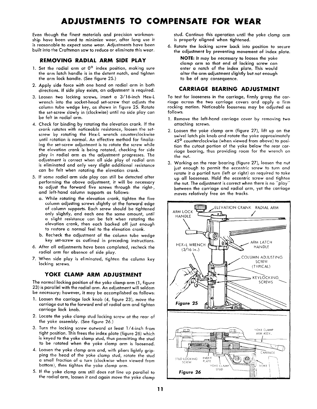
REMOVING RADIAL ARM SIDE PLAY
1. Set the radial arm at 0° index position, making sure
the arm latch handle is in the detent notch, and tighten
the arm lock handle. (See figure 25.)
2. Apply side force with one hand on radial arm in both
directions. If side play exists, an adjustment is required.
3. Loosen two locking screws, insert a 3/16-inch Hex-L
wrench into the socket-head set-screw that adjusts the
column tube wedge key, as shown in figure 25. Rotate
the set-screw slowly in (clockwise) until no side play can
be felt in radial arm.
4. Check for binding by rotating the elevation crank. If the
crank rotates with noticeable resistance, loosen the set-
screw by rotating the Hex-L wrench counterclockwise
until rotation is normal. An effective method for finaliz-
ing the set-screw adjustment is to rotate the screw while
the elevation crank is being rotated, checking for side
play in radial arm as the adjustment progresses. The
adjustment is correct when all side play of radial arm
is eliminated and only very slight additional resistance
can be felt when rotating the elevation crank.
5. If some radial arm side play can still be detected after
performing the above adjustment, it will be necessary
to adjust the forward five screws through the right-,
and left-hand column supports as follows:
a. While rotating the elevation crank, tighten the five
column adjusting screws slightly at the forward edge
of column supports. Each screw should be tightened
only slightly, and each one the same amount, until
a slight resistance can be felt when rotating the
elevation crank, then each backed off just enough
to restore a normal feel to the elevation crank.
b. Recheck the adjustment of the column tube wedge
key set-screw as outlined in preceding instructions.
6. After all adjustments have been completed, recheck the
radial arm for absence of side play.
7. When side play is eliminated, tighten the column key
locking screws.
YOKE CLAMP ARM ADJUSTMENT
The normal locking position of the yoke clamp arm (1, figure
23) is parallel with the radial arm. An adjustment will seldom
be necessary; however, it may be accomplished as follows:
1. Loosen the carriage lock knob (4, figure 23), move the
carriage out to the forward end of radial arm and tighten
carriage lock knob.
2. Locate the yoke clamp stud locking screw at the rear of
the yoke assembly. (See figure 26.)
3. Turn the locking screw outward at least 1/4-inch from
tight position. This frees the index plate (figure 26/which
is keyed to the yoke clamp stud, thus permitting the stud
to be rotated when the yoke clamp arm is loosened.
4. Loosen the yoke clamp arm and, with pliers lightly grip-
ping the head of the yoke clamp stud, rotate the stud
a small fraction of a turn (clockwise when viewed from
bottom!, then tighten the yoke clamp arm.
5. If the yoke clamp arm still does not line up parallel to
the radial arm, loosen it and again move the yoke clamp
stud. Continue this operation until the yoke clamp arm
is properly aligned when tightened.
6. Rotate the lacking screw back into position to secure
the adjustment by preventing movement of index plate.
NOTE: It may be necessary to loosen the yoke
clamp arm so that end of locking screw can
enter a notch of the index plate. This would
alter the arm adjustment slightly but not enough
to be of any consequence.
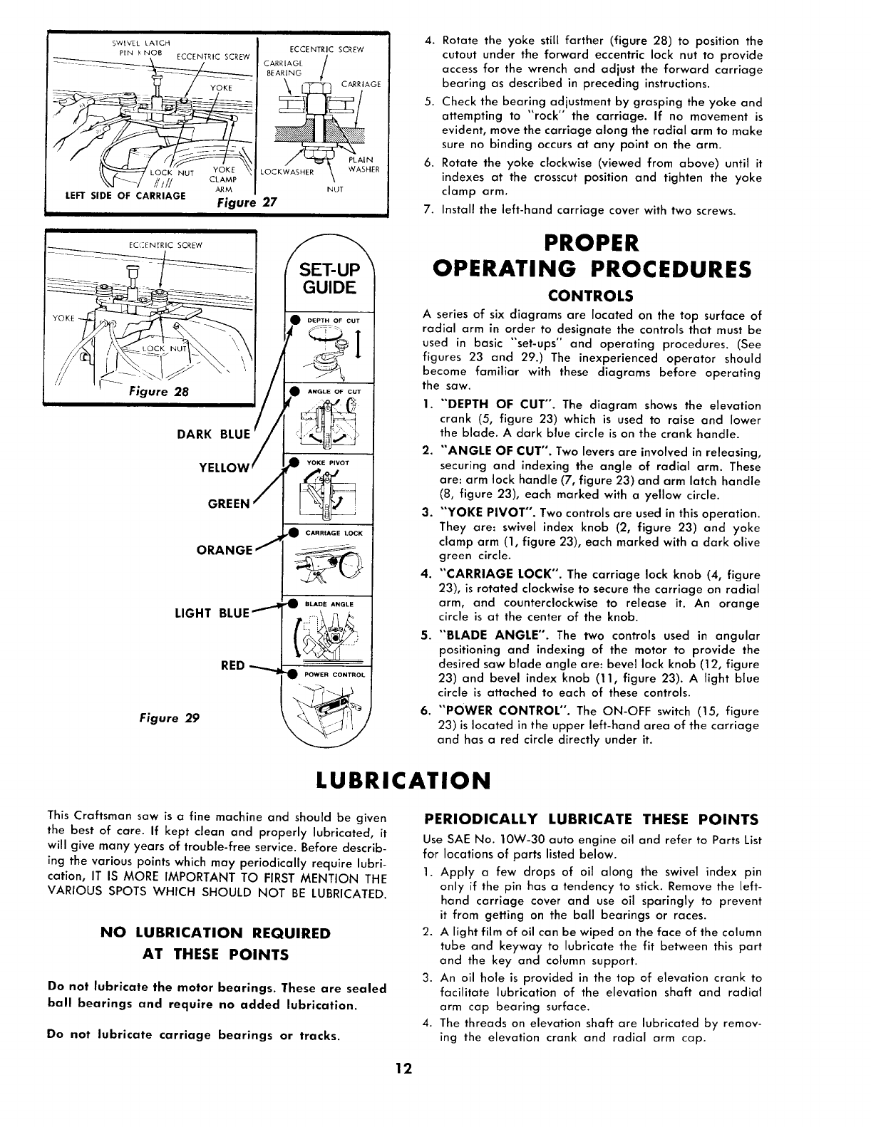
CARRIAGE BEARING ADJUSTMENT
To test for looseness in the carriage, firmly grasp the car-
riage across the two carriage covers and apply a firm
rocking motion. Noticeable looseness may be adjusted as
follows:
1. Remove the left-hand carriage cover by removing two
attaching screws.
2. Loosen the yoke clamp arm (figure 27), lift up on the
swivel latch pin knob and rotate the yoke approximately
45 ° counterclockwise (when viewed from above) to posi-
tion the cutout portion of the yoke below the rear car-
riage bearing, thus providing room for the wrench on
the nut.
3. Working on the rear bearing (figure 27), loosen the nut
just enough to permit the eccentric screw to turn and
rotate it a partial turn (left or right) as required to take
up all looseness. Hold the eccentric screw and tighten
the nut. The adjustment is correct when there is no "'play'"
between the carriage and radial arm, yet the carriage
moves relatively free on the tracks.
ARM ASS¥.
11
i
SWIVEL LATCH
PEN _ NOB ECCENTRIC SCREW
_[-'-_-/ _'t// aAM_
A/1M
LEFT SIDE OF CARRIAGE Figure 27
EC_ZENTRIC SCREW
Figure 28
DARK
YE
GREEN
ORANGE
LIGHT
RED
Figure 29
ECCENTRIC SCREW
CARRIAGE /
BEARING !/ AGE
LOCKWASHER \ WASHER
NUT
SET-UP
GUIDE
DEPTH OF CUT
ANGLE OF CUT
CARRIAGE LOCK
POWER CONTROL
4. Rotate the yoke still farther (figure 28) to position the
cutout under the forward eccentric lock nut to provide
access for the wrench and adjust the forward carriage
bearing as described in preceding instructions.
5. Check the bearing adjustment by grasping the yoke and
attempting to "rock" the carriage. If no movement is
evident, move the carriage along the radial arm to make
sure no binding occurs at any point on the arm.
6. Rotate the yoke clockwise (viewed from above) until it
indexes at the crosscut position and tighten the yoke
clamp arm.
7. Install the left-hand carriage cover with two screws.
PROPER
OPERATING PROCEDURES
CONTROLS
A series of six diagrams are located on the top surface of
radial arm in order to designate the controls that must be
used in basic "set-ups" and operating procedures. (See
figures 23 and 29.) The inexperienced operator should
become familia_ with these diagrams before operating
the saw.
1. "'DEPTH OF CUT". The diagram shows the elevation
crank (5, figure 23) which is used to raise and lower
the blade. A clark blue circle is on the crank handle.
2. "'ANGLE OF CUT". Two levers are involved in releasing,
securing and indexing the angle of radial arm. These
are: arm lock handle (7, figure 23) and arm latch handle
(_8, figure 23), each marked with a yellow circle.
3. "'YOKE PIVOT". Two controls are used in this operation.
They are: swivel index knob (2, figure 23) and yoke
clamp arm (1, figure 23), each marked with a dark olive
green circle.
4. "'CARRIAGE LOCK". The carriage lock knob (4, figure
23), is rotated clockwise to secure the carriage on radial
arm, and counterclockwise to release it. An orange
circle is at the center of the knob.
5. "'BLADE ANGLE". The two controls used in angular
positioning and indexing of the motor to provide the
desired saw blade angle are: bevel lock knob (12, figure
23) and bevel index knob (11, figure 23). Alight blue
circle is attached to each of these controls.
6. "POWER CONTROL". The ON-OFF switch (15, figure
23) is located in the upper left-hand area of the carriage
and has ared circle directly under it.
LUBRICATION
This Craftsman saw is a fine machine and should be given
the best of care. If kept clean and properly lubricated, it
will give many years of trouble-free service. Before describ-
ing the various points which may periodically require lubri-
cation, IT IS MORE IMPORTANT TO FIRST MENTION THE
VARIOUS SPOTS WHICH SHOULD NOT BE LUBRICATED.
NO LUBRICATION REQUIRED
AT THESE POINTS
Do not lubricate the motor bearings. These are sealed
ball bearings and require no added lubrication.
Do nat lubricate carriage bearings or tracks.
PERIODICALLY LUBRICATE THESE POINTS
Use SAE No. 10W-30 auto engine oil and refer to Parts List
for locations of parts listed below.
1. Apply a few drops of oil along the swivel index pin
only if the pin has a tendency to stick. Remove the left-
hand carriage cover and use oil sparingly to prevent
it from getting on the ball bearings or races.
2. A light film of oil can be wiped on the face of the column
tube and keyway to lubricate the fit between this part
and the key and column support.
3. An oil hole is provided in the top of elevation crank to
facilitate lubrication of the elevation shaft and radial
arm cap bearing surface.
4. The threads on elevation shaft are lubricated by remov-
ing the elevation crank and radial arm cap.
12
STANDARD SAW OPERATIONS
PRELIMINARY CROSS-CUT AT THE
0 ° POSITION
1. Loosen the carriage lock knob (4, figure 23) and move
the carriage to position the saw just forward of the rip
fence (See figure 22.)
2. Lower the radial arm until the saw blade just clears the
table top.
3. Tighten the carriage lock knob (4, figure 23.)
CAUTION: Before making the cut, make sure
the arm latch handle (8, figure 23) is fully en-
gaged in the detent notch.
4. Plug in the power cord (if not already connected).
5. Insert the safety lock key (figure 24) and pull the switch
lever out to "ON" position.
6. Lower the radial arm, by rotating the elevation crank,
until the saw blade cuts into the table top surface to a
depth of approximately 1/32-inch.
7. Complete the blade clearance groove in the table and
rip fence as follows:
a. Grasp the handle (14, figure 23) with the left hand
and loosen the carriage lock knob (4, figure 23) with
the right hand.
b. Slowly pull the carriage with the right hand out to
the extreme end of its travel.
c. Push the carriage slowly rearward to the extreme
end of the travel. This stroke will cut through the
rip fence.
d. Push the switch to "'OFF" position.
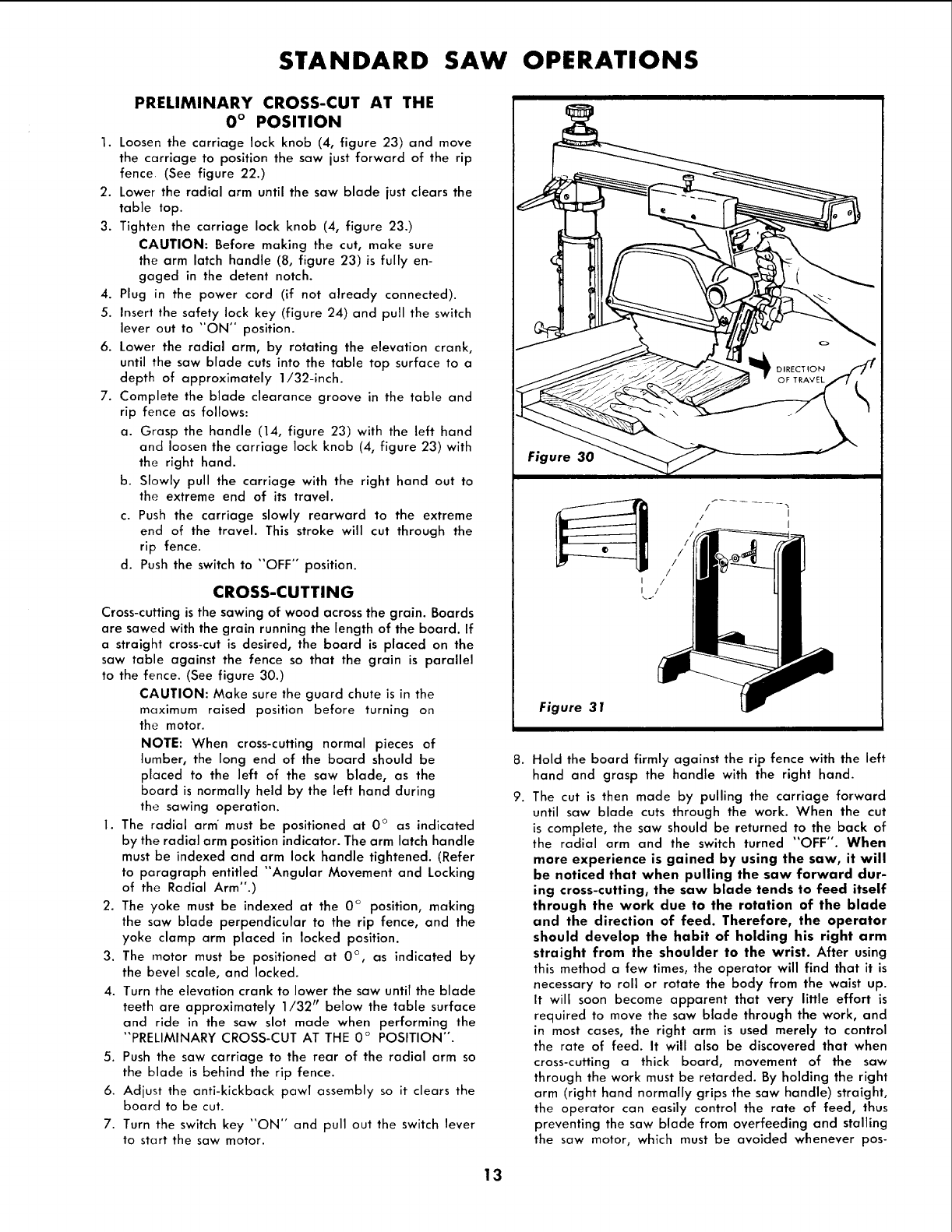
CROSS-CUTTING
Cross-cuttingis the sawing of wood across the grain. Boards
are sawed with the grain running the length of the board. If
a straight cross-cut is desired, the board is placed on the
saw table against the fence so that the grain is parallel
to the fence. (See figure 30.)
CAUTION: Make sure the guard chute is in the
maximum raised position before turning on
the motor.
NOTE: When cross-cutting normal pieces of
lumber, the long end of the board should be
placed to the left of the saw blade, as the
board is normally held by the left hand during
the sawing operation.
1. The radial arm' must be positioned at 0 ° as indicated
by the radial arm position indicator. The arm latch handle
must be indexed and arm lock handle tightened. (Refer
to paragraph entitled "Angular Movement and Locking
of the Radial Arm".)
2. The yoke must be indexed at the 0 ° position, making
the saw blade perpendicular to the rip fence, and the
yoke clamp arm placed in locked position.
3. The motor must be positioned at 0 °, as indicated by
the bevel scale, and locked.
4. Turn the elevation crank to lower the saw until the blade
teeth are approximately 1/32 prbelow the table surface
and ride in the saw slot made when performing the
"PRELIMINARY CROSS-CUT AT THE 0 ° POSITION".
5. Push the saw carriage to the rear of the radial arm so
the blade is behind the rip fence.
6. Adjust the anti-kickback pawl assembly so it clears the
board to be cut.
7. Turn the switch key "ON'" and pull out the switch lever
to start the saw motor.
I/
I/
Figure 31
8.
9.
Hold the board firmly against the rip fence with the left
hand and grasp the handle with the right hand.
The cut is then made by pulling the carriage forward
until saw blade cuts through the work. When the cut
is complete, the saw should be returned to the back of
the radial arm and the switch turned "OFF". When
more experience is gained by using the saw, it will
be noticed that when pulling the saw forward dur-
ing cross-cutting, the saw blade tends to feed itself
through the work due to the rotation of the blade
and the direction of feed. Therefore, the operator
should develop the habit of holding his right arm
straight from the shoulder to the wrist. After using
this method a few times, the operator will find that it is
necessary to roll or rotate the body from the waist up.
It will soon become apparent that very little effort is
required to move the saw blade through the work, and
in most cases, the right arm is used merely to control
the rate of feed. It will also be discovered that when
cross-cutting a thick board, movement of the saw
through the work must be retarded. By holding the right
arm /right hand normally grips the saw handle) straight,
the operator can easily control the rate of feed, thus
preventing the saw blade from overfeeding and stalling
the saw motor, which must be avoided whenever pos-
13
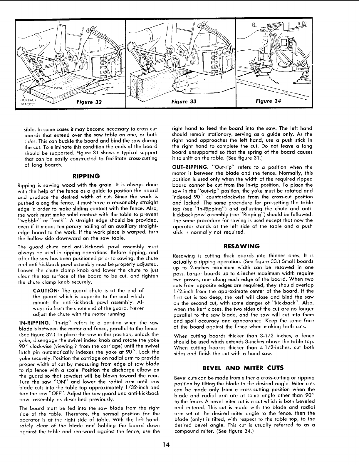
sible. In some cases it may become necessary to cross-cut
boards that extend over the saw table on one, or both
sides. This can buckle the board and bind the saw during
the cut. To eliminate this condition the ends of the board
should be supported. Figure 31 shows a typical support
that can be easily constructed to facilitate cross-cutting
of long boards.
RIPPING
Ripping is sawing wood with the grain. It is always done
with the help of the fence as a guide to position the board
and produce the desired width of cut. Since the work is
pushed along the fence, it must have a reasonably straight
edge in order to make sliding contact with the fence. Also,
the work must make solid contact with the table to prevent
"wobble" or "rock". A straight edge should be provided,
even if it means temporary nailing of an auxiliary straight-
edge board to the work. If the work piece is warped, turn
the hollow side downward on the saw table.
The guard chute and anti-kickback pawl assembly must
always be used in ripping operations. Before ripping, and
after the saw has been positioned prior to sawing, the chute
and anti-kickback pawl assembly must be properly adjusted.
Loosen the chute clamp knob and lower the chute to just
clear the top surface of the board to be cut, and tighten
the chute clamp knob securely.
CAUTION: The guard chute is at the end of
the guard which is opposite to the end which
mounts the anti-kickback pawl assembly. Al-
ways rip from the chute end of the guard. Never
adjust the chute with the motor running.
IN-RIPPING. "In-rip" refers to a position when the saw
blade is between the motor and fence, parallel to the fence.
(See figure 32.) To place the saw in this positior., unlock the
yoke, disengage the swivel index knob and rotate the yoke
90 ° clockwise (viewing it from the carriage) until the swivel
latch pin automatically indexes the yoke at 90 ° . Lock the
yoke securely. Position the carriage on radial arm to provide
proper width of cut by measuring from edge of saw blade
to rip fence with a scale. Position the discharge elbow on
the guard so that sawdust will be blown toward the rear.
Turn the saw "ON" and lower the radial arm until saw
blade cuts into the table top approximately 1/32-inch and
turn the saw "OFF". Adjust the saw guard and anti-kickback
pawl assembly as described previously.
The board must be fed into the saw blade from the right
side of the table. Therefore, the normal position for the
operator is at the right side of table. With the left hand,
safely clear of the blade and holding the board down
against the table and rearward against the fence, use the
right hand to feed the board into the saw. The left hand
should remain stationary, serving as a guide only. As the
right hand approaches the left hand, use a push stick in
the right hand to complete the cut. Do not leave a long
board unsupported so that the spring of the board causes
it to shift on the table. (See figure 31.)
OUT-RIPPING. "Out-rip'* refers to a position when the
motor is between the blade and the fence. Normally, this
position is used only when the width of the required ripped
board cannot be cut from the in-rip position. To place the
saw in the "out-rip" position, the yoke must be rotated and
indexed 90 ° counterclockwise from the cross-cut position
and locked. The same procedure for pre-setting the table
top (see "In-Ripping") and adjusting the chute and anti-
kickback pawl assembly (see "Ripping") should be followed.
The same procedure for sawing is used except that now the
operator stands at the left side of the table and apush
stick is normally not required.
RESAWlNG
Resawing is cutting thick boards into thinner ones. It is
actually a ripping operation. (See figure 33.) Small boards
up to 2-inches maximum width can be resawed in one
pass. Larger boards up to 4-inches maximum width require
two passes, one along each edge of the board. When two
cuts from opposite edges are required, they should overlap
1/2-inch from the approximate center of the board. If the
first cut is too deep, the kerf will close and bind the saw
on the second cut, with some danger of "kickback". Also,
when the kerf closes, the two sides of the cut are no longer
parallel to the saw blade, and the saw will cut into them
and spoil accuracy and appearance. Keep the same face
of the board against the fence when making both cuts.
When cutting boards thicker than 3-1/2 inches, a fence
should be used which extends 3-inches above the table top.
When cutting boards thicker than 4-1/2-inches, cut both
sides and finish the cut with a hand saw.
BEVEL AND MITER CUTS
Bevel cuts can be made from either a cross-cutting or ripping
position by tilting the blade to the desired angle. Miter cuts
can be made only from a cross-cutting position when the
blade and radial arm are at some angle other than 90 °
to the fence. A bevel miter cut is a cut which is both beveled
and mitered. This cut is made with the blade and radial
arm set at the desired miter angle to the fence, then the
blade (only) is tilted, with respect to the table top, to the
desired bevel angle. This cut is usually referred to as a
compound miter. (See figure 34.)
14
USE OF THE DADO HEAD
The dado saw (or head) is a special set of blades for cutting
grooves and dados. The Craftsman 8-inch Kromedge Dado
Set may be purchased at any Sears Retail Store or Catalog
Order House. The complete head consists of two outside
blades 1/8-inch thick, six chipper blades 1/8-inch thick
and paper washers for 1/16-inch width adjustments. With
these blades, grooves may be made in widths of 1/8-inch,
1/4-inch, and additional widths in steps increased by
1/16-inch each, up to a maximum of 13/16-inch. Outside
blades may be used alone, but chippers cannot be used
alone. When the maximum 13/16-inch width of dado is
used on the motor shaft, the outside loose collar must not
be used. The width of the dado can be reduced while using
the loose collar and two or more passes may be made with
the work to obtain the desired width of cut. Whenever two
or more chippers are used, the cutting ends should be
staggered as evenly as possible around the circumference.
Fractional adjustments in thickness of the head can be
made by using paper washers between the outside blades
and chippers.
Dado head operations are essentially the same as those
operations using a standard saw blade--but the dado
head takes a bigger bite, therefore, the work-piece should
be held more firmly. When a groove wider than the dado
head is needed, make two or more passes, with cuts spaced
to overlap a trifle. Dado work is performed in the cross-cut
position. Ploughing is done in the ripping position. If the
rip or plough position is used, the saw guard and anti-
kickback pawl assembly should be adjusted as described
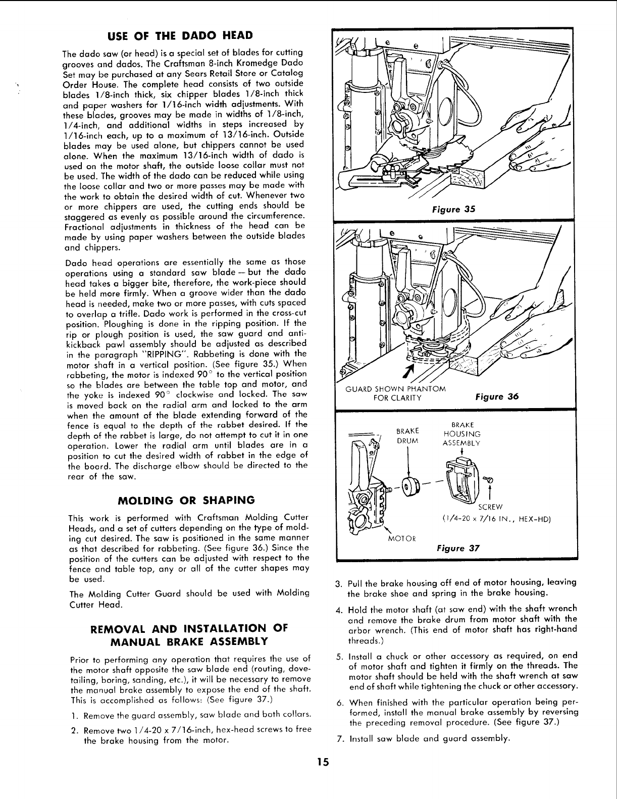
in the paragraph "RIPPING". Rabbeting is done with the
motor shaft in a vertical position. (See figure 35.) When
rabbeting, the motor is indexed 90 ° to the vertical position
so the blades are between the table top and motor, and
the yoke is indexed 90 ° clockwise and locked. The saw
is moved back on the radial arm and locked to the arm
when the amount of the blade extending forward of the
fence is equal to the depth of the rabbet desired. If the
depth of the rabbet is large, do not attempt to cut it in one
operation. Lower the radial arm until blades are in a
position to cut the desired width of rabbet in the edge of
the board. The discharge elbow should be directed to the
rear of the saw.
MOLDING OR SHAPING
This work is performed with Craftsman Molding Cutter
Heads, and a set of cutters depending on the type of mold-
ing cut desired. The saw is positioned in the same manner
as that described for rabbeting. (See figure 36.) Since the
position of the cutters can be adjusted with respect to the
fence and table top, any or all of the cutter shapes may
be used.
The Molding Cutter Guard should be used with Molding
Cutter Head.
REMOVAL AND INSTALLATION OF
MANUAL BRAKE ASSEMBLY
Prior to performing any operation that requires the use of
the motor shaft opposite the saw blade end (routing, dove-
tailing, boring, sanding, etc.), it will be necessary to remove
the manual broke assembly to expose the end of the shaft.
This is accomplished as follows: (See figure 37.)
1. Remove the guard assembly, saw blade and both cottars.
2. Remove two 1/4-20 x 7!16-inch, hex-head screws to free
the brake housing from the motor.
7
Figure 35
BRAKE
BRAKE
_'--_/ DRUM HOUSING
ASSEMBLY
w
(7/4-20 x 7/16 IN., HEX-HD)
MOTOR
Figure 37
I
3. Pull the brake housing off end of motor housing, leaving
the brake shoe and spring in the brake housing.
4. Hold the motor shaft (at saw end) with the shaft wrench
and remove the brake drum from motor shaft with the
arbor wrench. (This end of motor shaft has right-hand
threads.)
5. Install a chuck or other accessory as required, on end
of motor shaft and tighten it firmly on the threads. The
motor shaft should be held with the shaft wrench at saw
end of shaft while tightening the chuck or other accessory.
6. When finished with the particular operation being per-
formed, install the manual brake assembly by reversing
the preceding removal procedure. (See figure 37.)
7. Install saw blade and guard assembly.
15

ROUTING AND DOVETAILING
Routing and dovetailing are accomplished with the motor
indexed and locked 90 ° from horizontal, except that this
time the externally threaded stub end (opposite the normal
blade end) is between the motor and table top. The follow-
ing chucks will mate, with this external 1/2-20 thread.
(See figure 38.)
0-inch to 1/4-inch Chuck
5/64-inch to 1/2-inch Key Chuck
The following touters and dovetails are recommended:
1/8-inch router
1/4-inch router 3/8-inch dovetail
3/8-inch router 1/2-inch dovetail
1/2-inch router
5/8-inch router
Routing may be performed by either moving the work with
a stationary router, or by clamping the work to the table
and moving the router. Always approach the router bit
from the left-hand side of the saw.
BORING
The saw may be converted to a horizontal drill for boring
by removing the manual brake assembly and using one of
the recommended chucks and proper drill. For drilling holes
on an angle, the radial arm should be positioned to the
desired angle while the work is parallel to the fence. (See
figure 39.) Be sure to install the brake assembly when boring
operations have been completed.
SANDING
Using the sanding disc, mounted on motor shaft, the saw
may be converted into a sander that will operate in any
position. (See figure 40.)
SAW KERF IN
_ENCE AND TABLE
_p/ FENCE
f SCALE
Figure 41
1.
2.
3.
4.
5.
HELPFUL HINTS
The life of the composition saw table may be greatly
lengthened if a 1/4-inch piece of plywood is tacked to
the table top after leveling. Then all cutting would be
done in the added piece of plywood instead of the
table top.
There is a possibility that during (or after) shipment, the
wood front table; spacer board; or rear table might
become slightly warped. Lay a straight-edge across the
surface of the table and check for gaps or high spots
on the table. Any portions of the table that are not flat
should be planed and sanded until flat. Sanding can be
done by using one of the two key chucks referred to
under "ROUTING" and a Craftsman moulded rubber
6-inch sanding disc.
When sanding the table top or routing with the work
stationary, the arm latch handle may be prevented from
automatically indexing by raising it to the vertical posi-
tion. (See figure 40.)
A scale may be attached to the fence to aid the operator
when measuring lengths during cross-cut operations. This
is accomplished by tacking a yard stick to the fence as
shown. (See figure 41.)
In the event the fence is warped and cannot be straight-
ened by tightening the table clamps, proceed as follows:
a. Remove the fence and replace it with a temporary
fence made from a straight piece of scrap lumber.
Proceed to cut slots in the original fence where the
gap between the fence and front table was deter-
mined to be the greatest. (See figure 42 for slotting
arrangement.)
b. Replace the fence (after slotting) behind the front
table with the slots toward the rear and tighten the
table clamps.
BLADE
SLOTTING FENCE TO
CORRECT FOR WARPAGE
Figure 42
16
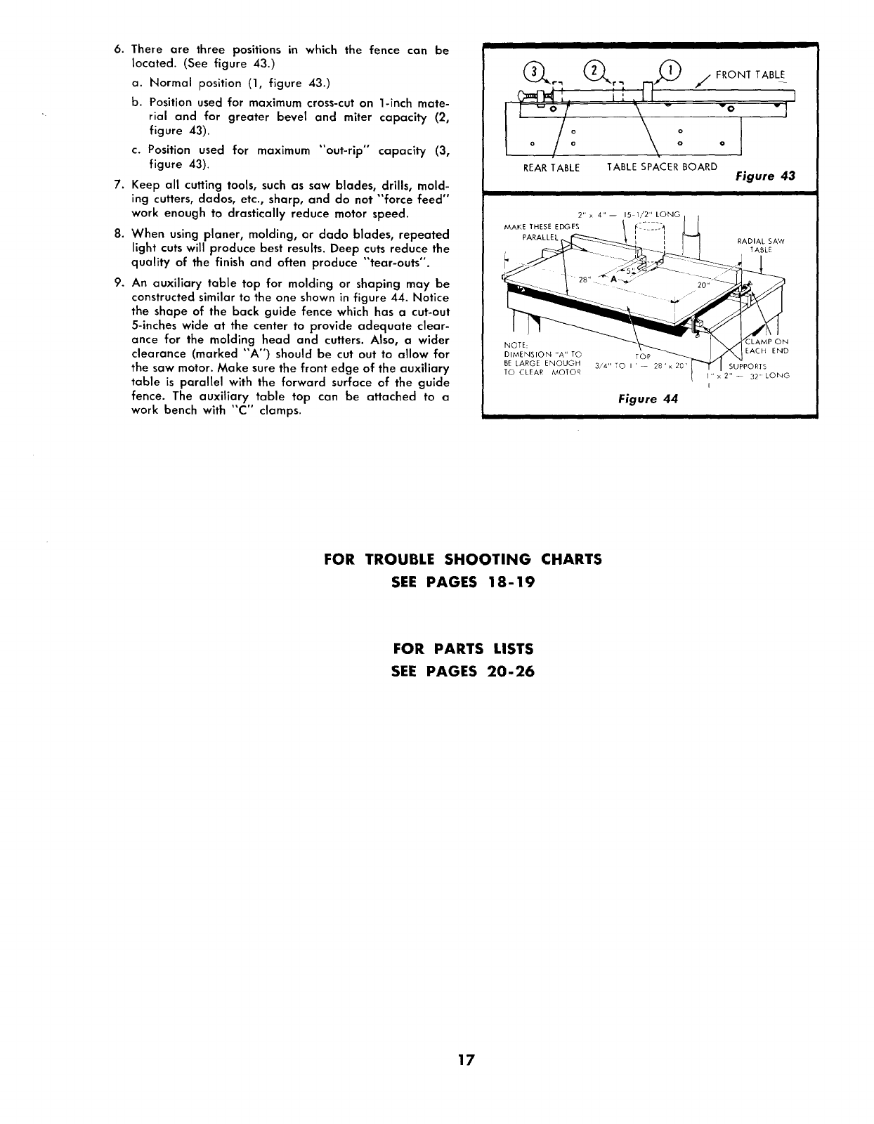
6. There are three positions in which the fence can be
located. (See figure 43.)
a. Normal position (1, figure 43.)
b. Position used for maximum cross-cut on 1-inch mate-
rial and for greater bevel and miter capacity (2,
figure 43).
c. Position used for maximum "out-rip" capacity (3,
figure 43).
7. Keep all cutting tools, such as saw blades, drills, mold-
ing cutters, dados, etc., sharp, and do not "force feed"
work enough to drastically reduce motor speed.
8. When using planer, molding, or dado blades, repeated
light cuts will produce best results. Deep cuts reduce the
quality of the finish and often produce "tear-outs".
9. An auxiliary table top for molding or shaping may be
constructed similar to the one shown in figure 44. Notice
the shape of the back guide fence which has a cut-out
5-inches wide at the center to provide adequate clear-
ance for the molding head and cutters. Also, a wider
clearance (marked "A") should be cut out to allow for
the saw motor. Make sure the front edge of the auxiliary
table is parallel with the forward surface of the guide
fence. The auxiliary table top can be attached to a
work bench with "C '° clamps.
ii
REAR TABLE TABLE SPACER BOARD
f/, FRONT TABLE
I
vO v I
Figure 43
RADIAL SAW
TABLE
Figure 44
I
LAMP ON
EACH END
SUPPORTS
I" x2" -- 32" LONG
I
FOR TROUBLE SHOOTING CHARTS
SEE PAGES 18-19
FOR PARTS LISTS
SEE PAGES 20°26
17
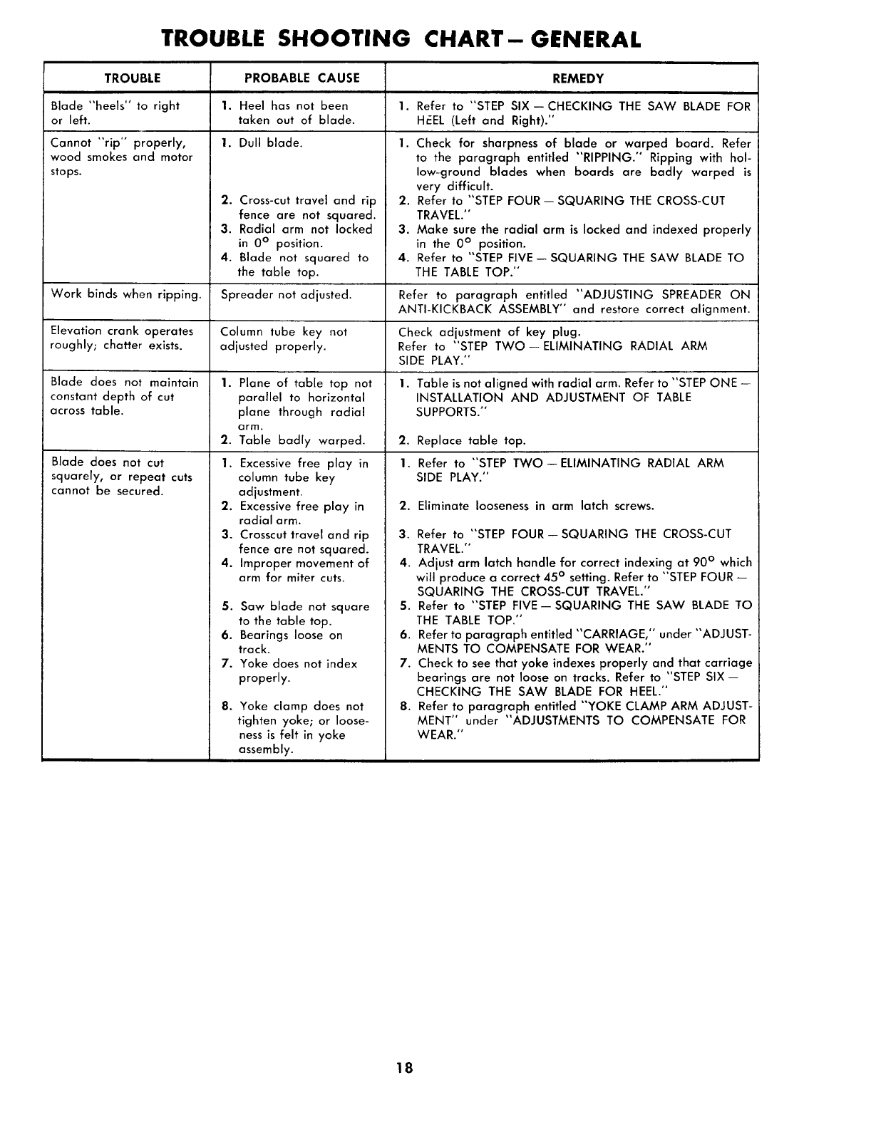
TROUBLE SHOOTING CHART-GENERAL
TROUBLE
Blade "heels" to right
or left.
Cannot "rip" properly,
wood smokes and motor
stops.
Work binds when ripping.
Elevation crank operates
roughly; chatter exists.
Blade does not maintain
constant depth of cut
across table.
Blade does not cut
squarely, or repeat cuts
cannot be secured.
PROBABLE CAUSE REMEDY
1. Heel has not been 1. Refer to "STEP SIX--CHECKING THE SAW BLADE FOR
taken out of blade. Hr_EL (Left and Right)."
1. Dull blade. 1.
2. Cross-cut travel and rip
fence are not squared.
3. Radial arm not locked
in 0 ° position.
4. Blade not squared to
the table top.
2.
3.
4.
Check for sharpness of blade or warped board. Refer
to the paragraph entitled "RIPPING." Ripping with hol-
low-ground blades when boards are badly warped is
very difficult.
Refer to "STEP FOUR -- SQUARING THE CROSS-CUT
TRAVEL."
Make sure the radial arm is locked and indexed properly
in the 0° position.
Refer to "STEP FIVE -- SQUARING THE SAW BLADE TO
THE TABLE TOP."
Spreader not adjusted. Refer to paragraph entitled "ADJUSTING SPREADER ON
ANTI-KICKBACK ASSEMBLY" and restore correct alignment.
Column tube key not Check adjustment of key plug.
adjusted properly. Refer to "STEP TWO--ELIMINATING RADIAL ARM
SIDE PLAY."
1.
2.
Plane of table top not
parallel to horizontal
plane through radial
arm.
Table badly warped.
1. Excessive free play in
column tube key
adjustment.
2. Excessive free play in
radial arm.
3. Crosscut travel and rip
fence are not squared.
4. Improper movement of
arm for miter cuts.
5. Saw blade not square
to the table top.
6. Bearings loose on
track.
7. Yoke does not index
properly.
B° Yoke clamp does not
tighten yoke; or loose-
ness is felt in yoke
assembly.
1. Table is not aligned with radial arm. Refer to "STEP ONE --
INSTALLATION AND ADJUSTMENT OF TABLE
SUPPORTS."
2. Replace table top.
1. Refer to "STEP TWO--ELIMINATING RADIAL ARM
SIDE PLAY."
2. Eliminate looseness in arm latch screws.
3. Refer to "STEP FOUR--SQUARING THE CROSS-CUT
TRAVEL."
4. Adjust arm latch handle for correct indexing at 90 ° which
will produce a correct 45° setting. Refer to "STEP FOUR --
SQUARING THE CROSS-CUT TRAVEL."
5. Refer to "STEP FIVE--SQUARING THE SAW BLADE TO
THE TABLE TOP."
6. Refer to paragraph entitled "CARRIAGE," under "ADJUST-
MENTS TO COMPENSATE FOR WEAR."
7. Check to see that yoke indexes properly and that carriage
bearings are not loose on tracks. Refer to "STEP SIX-
CHECKING THE SAW BLADE FOR HEEL."
8. Refer to paragraph entitled "YOKE CLAMP ARM ADJUST-
MENT" under "ADJUSTMENTS TO COMPENSATE FOR
WEAR."
18
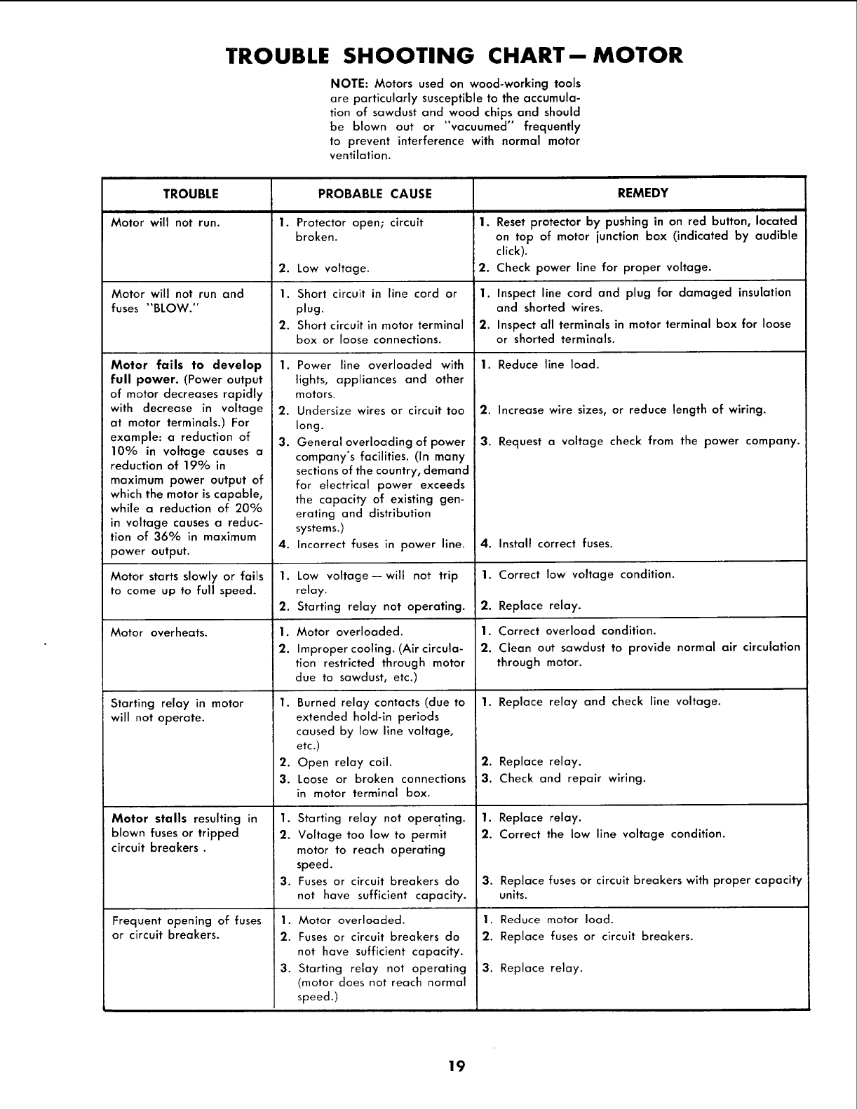
TROUBLE SHOOTING CHART--MOTOR
NOTE: Motors used on wood-working tools
are particularly susceptible to the accumula-
tion of sawdust and wood chips and should
be blown out or "vacuumed" frequently
to prevent interference with normal motor
ventilation.
TROUBLE
Motor will not run.
Motor will not run and
fuses "BLOW."
Motor fails to develop
full power. (Power output
of motor decreases rapidly
with decrease in voltage
at motor terminals.) For
example: a reduction of
10% in voltage causes a
reduction of 19% in
maximum power output of
which the motor is capable,
while a reduction of 20%
in voltage causes a reduc-
tion of 36% in maximum
power output.
Motor starts slowly or fails
to come up to full speed.
Motor overheats.
Starting relay in motor
will not operate.
Motor stalls resulting in
blown fusesor tripped
circuit breakers.
Frequent opening of fuses
or circuit breakers.
1.
2.
1.
2.
1.
2.
3.
4.
1.
2.
1.
2.
PROBABLE CAUSE
Protector open; circuit
broken.
Low voltage.
Short circuit in line cord or
plug.
Short circuit in motor terminal
box or loose connections.
Power line overloaded with
lights, appliances and other
motors.
Undersize wires or circuit too
long.
General overloading of power
company's facilities. (In many
sections of the country, demand
for electrical power exceeds
the capacity of existing gen-
erating and distribution
systems.)
Incorrect fuses in power line.
Low voltage--will not trip
relay.
Starting relay not operating.
Motor overloaded.
Improper cooling. (Air circula-
tion restricted through motor
due to sawdust, etc.)
1. Burned relay contacts (due to
extended hold-in periods
caused by low line voltage,
etc.)
2. Open relay coil.
3. Loose or broken connections
in motor terminal box.
1. Starting relay not operating.
2. Voltage too low to permit
motor to reach operating
speed.
3. Fuses or circuit breakers do
not have sufficient capacity.
1. Motor overloaded.
2. Fuses or circuit breakers do
not have sufficient capacity.
3. Starting relay not operating
/motor does not reach normal
speed.)
1.
2.
1.
2.
REMEDY
Reset protector by pushing in on red button, located
on top of motor junction box (indicated by audible
click).
Check power line for proper voltage.
Inspect line cord and plug for damaged insulation
and shorted wires.
Inspect all terminals in motor terminal box for loose
or shorted terminals.
1. Reduce line load.
2. Increase wire sizes, or reduce length of wiring.
3. Request a voltage check from the power company.
4. Install correct fuses.
1. Correct low voltage condition.
2. Replace relay.
1. Correct overload condition.
2. Clean out sawdust to provide normal air circulation
through motor.
1. Replace relay and check line voltage.
2. Replace relay.
3. Check and repair wiring.
1. Replace relay.
2. Correct the low line voltage condition.
3. Replace fuses or circuit breakers with proper capacity
units.
1. Reduce motor load.
2. Replace fuses or circuit breakers.
3. Replace relay.
19
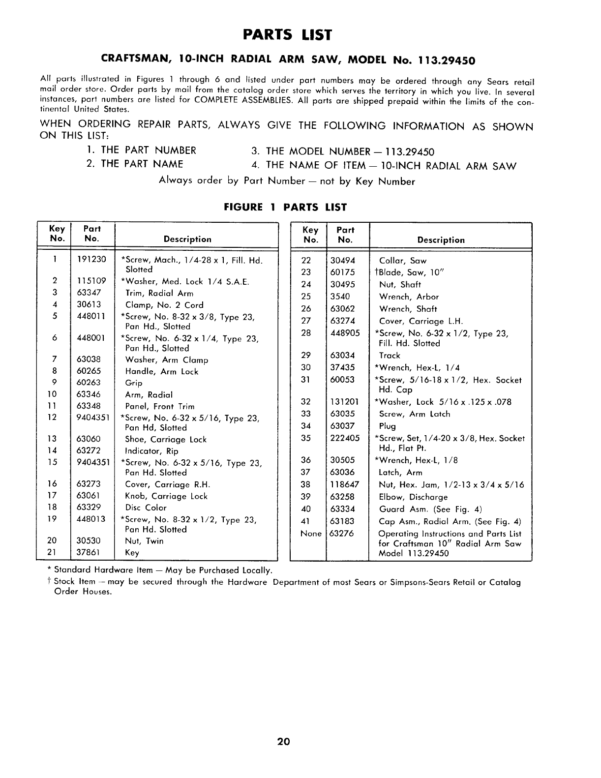
PARTS LIST
CRAFTSMAN, 10-INCH RADIAL ARM SAW, MODEL No. 113.29450
All parts illustrated in Figures 1 through 6 and listed under part numbers may be ordered through any Sears retail
mail order store. Order parts by mail from the catalog order store which serves the territory in which you live. In several
instances, part numbers are listed for COMPLETE ASSEMBLIES. All parts are shipped prepaid within the limits of the con-
tinental United States.
WHEN ORDERING REPAIR PARTS, ALWAYS GIVE THE FOLLOWING INFORMATION AS SHOWN
ON THIS LIST:
1. THE PART NUMBER 3. THE MODEL NUMBER--113.29450
2. THE PART NAME 4. THE NAME OF ITEM--10-INCH RADIAL ARM SAW
Always order by Part Number--not by Key Number
FIGURE 1 PARTS LIST
Key Port
No. No. Description
2
3
4
5
7
8
9
10
1!
12
13
14
15
16
17
18
19
20
21
191230
115109
63347
30613
448011
448001
63038
60265
60263
63346
63348
9404351
63060
63272
9404351
63273
63061
63329
448013
30530
37861
*Screw, Mach., 1/4-28 x 1, Fill. Hd.
Slotted
*Washer, Med. Lock 1/4 S.A.E.
Trim, Radial Arm
Clamp, No. 2 Cord
*Screw, No. 8-32 x 3/8, Type 23,
Pan Hd., Slotted
*Screw, No. 6-32 x 1/4, Type 23,
Pan Hd., Slotted
Washer, Arm Clamp
Handle, Arm Lock
Grip
Arm, Radial
Panel, Front Trim
*Screw, No. 6-32 x 5/16, Type 23,
Pan Hd, Slotted
Shoe, Carriage Lock
Indicator, Rip
*Screw, No. 6-32 x 5/16, Type 23,
Pan Hd. Slotted
Cover, Carriage R.H.
Knob, Carriage Lock
Disc Color
*Screw, No. 8-32 x 1/2, Type 23,
Pan Hd. Slotted
Nut, Twin
Key
* Standard Hardware Item -- May be Purchased Locally.
Key Part
No. No. Description
22 30494
23 60175
24 30495
25 3540
26 63062
27 63274
28 448905
29 63034
30 37435
31 60053
32 131201
33 63035
34 63037
35 222405
36 30505
37 63036
38 118647
39 63258
40 63334
41 63183
None 63276
Collar, Saw
tBlade, Saw, 10"
Nut, Shaft
Wrench, Arbor
Wrench, Shaft
Cover, Carriage L.H.
*Screw, No. 6-32 x 1/2, Type 23,
Fill. Hd. Slotted
Track
*Wrench, Hex-L, 1/4
*Screw, 5/16-18xl/2, Hex. Socket
Hd. Cap
*Washer, Lock 5/16 x .125 x .078
Screw, Arm Latch
Plug
*Screw, Set, 1/4-20 x 3/8, Hex. Socket
Hd., Flat Pt.
*Wrench, Hex-L, 1/8
Latch, Arm
Nut, Hex. Jam, 1/2-13 x 3/4 x 5/16
Elbow, Discharge
Guard Asm. (See Fig. 4)
Cap Asm., Radial Arm. (See Fig. 4)
Operating Instructions and Parts List
for Craftsman 10 r' Radial Arm Saw
Model 113.29450
tStock Item -may be secured through the Hardware Department of most Sears or Simpsons-Sears Retail or Catalog
Order Houses.
2O
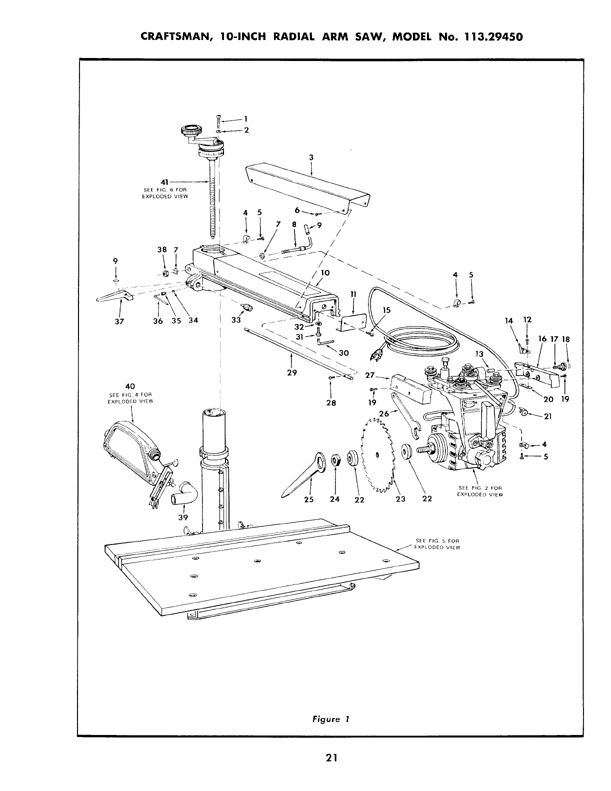
CRAFTSMAN, 10-INCH RADIAL ARM SAW, MODEL No. 113.29450
41-_
SEE FIG. 6 FOR
EXPLODED VIEW
38 7
37 36 35 34
45
SEE FIG 2 FOR
EXPLODED VIEW
/ JJ_
__ SEE FIG 5 FOR
PLODED VIEW
14 12
-
_ '_"2o 1!
L..
I
_5
Figure 1
21
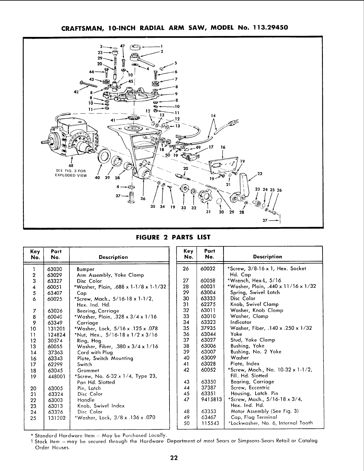
CRAFTSMAN, l O-INCH RADIAL ARM SAW, MODEL No. 113.29450
14
I
SEE FIG. 3 FOR
EXPLODED VIEW 40 39
o17 16
_so 19 19
35 34 19 33 32 /
31 30 29 28
FIGURE 2 PARTS LIST
Key Part
No. No. Description
1
2
3
4
5
6
63030
63029
63327
60051
63407
60025
7 63026
8 60040
9 63349
10 131201
11 124824
12 30574
13 60055
14 37363
16 63343
17 62299
18 63045
19 448001
Bumper
Arm Assembly, Yoke Clamp
Disc Color
*Washer, Plain, .688 x 1-1/8 x 1-1/32
20 63005
21 63324
22 63003
23 63013
24 63326
25 131202
Cap
*Screw, Math., 5/16-18 x 1-1/2,
Hex. Ind. Hd.
Bearing, Carriage
*Washer, Plain, .328 x 3/4 x 1/16
Carriage
*Washer, Lock, 5/16 x .125 x .078
*Nut, Hex., 5/16-18x 1/2x3/16
Ring, Hog
Washer, Fiber, .380 x 3/4 x 1/16
Cord with Plug
Plate, Switch Mounting
Switch
Grommet
*Screw, No. 6-32 x 1/4, Type 23,
Pan Hd. Slotted
Pin, Latch
Disc Color
Handle
Knob, Swivel Index
Disc Color
*Washer, Lock, 3/8 x .136x .070
Key
No. Description
26
27
28
29
30
31
32
33
34
35
36
37
38
39
4O
41
42
43
44
45
47
48
49
5O
Pa rt
No.
60032
60058
60031
*Screw, 3/8-16 x 1, Hex. Socket
Hd. Cap
*Wrench, Hex-L, 5/16
*Washer, Plain, .440 x 11/16 x 1/32
63004
63333
62275
63011
63010
63323
37935
63044
63027
63006
63007
63009
63028
60052
63350
37387
63351
9415813
63353
63467
115543
Spring, Swivel Latch
Disc Color
Knob, Swivel Clamp
Washer, Knob Clamp
Washer, Clamp
Indicator
Washer, Fiber, .140 x .250 x 1/32
Yoke
Stud, Yoke Clamp
Bushing, Yoke
Bushing, No. 2 Yoke
Washer
Plate, Index
*Screw, Mach., No. 10-32 x 1-1/2,
Fill. Hd. Slotted
Bearing, Carriage
Screw, Eccentric
Housing, Latch Pin
*Screw, Mach., 5/16-18 x 3/4,
Hex. Ind. Hd.
Motor Assembly (See Fig. 3)
Cap, Flag Terminal
*Lockwasher, No. 6, Internal Tooth
* Standard Hardware Item May be Purchased Locally.
tStock Item--may be secured through the Hardware Department of most Sears or Simpsons-SearsRetail or Catalog
Order Houses.
22
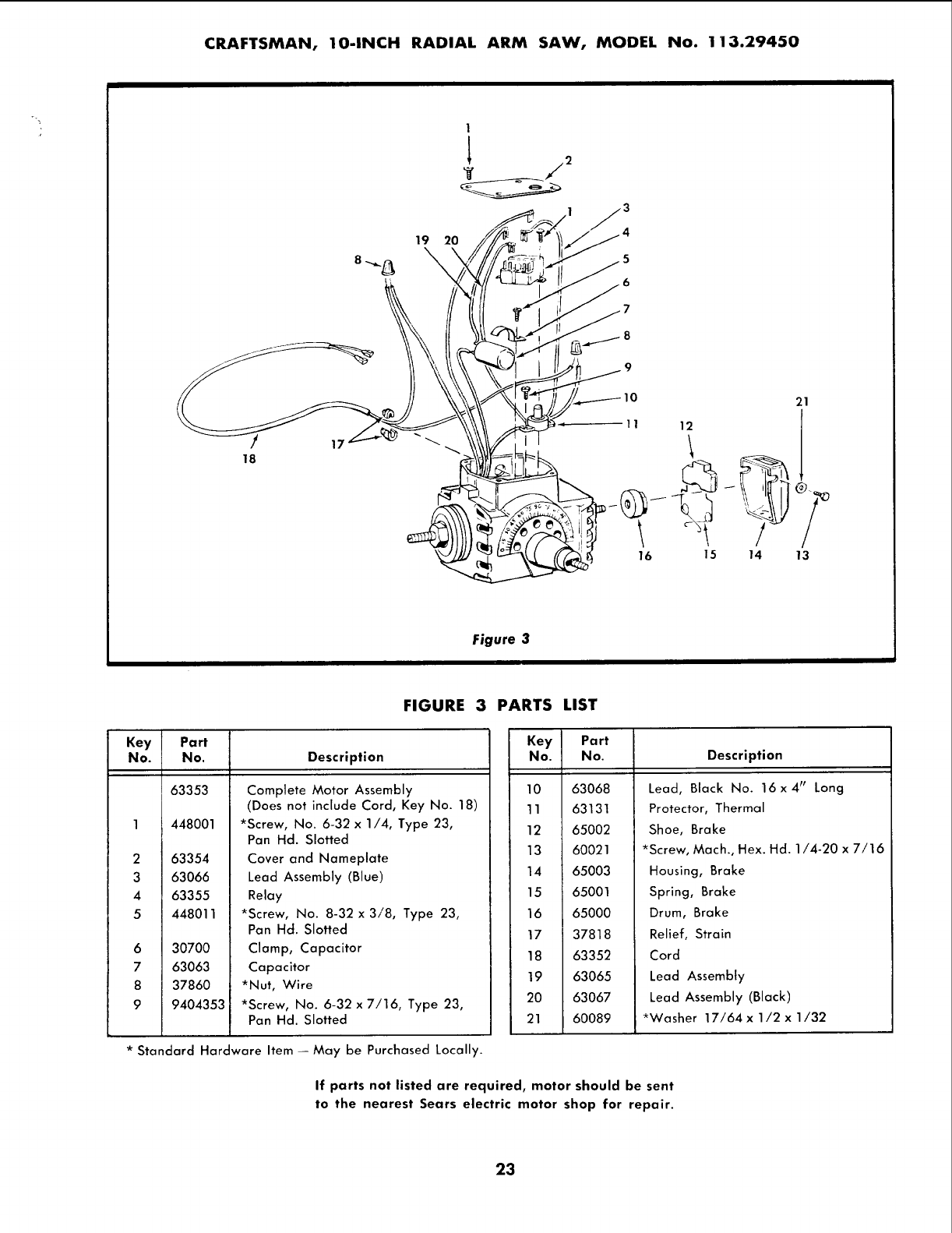
CRAFTSMAN, 10-INCH RADIAL ARM SAW, MODEL No. 113.29450
/
18 17
19 20
1
Figure 3
3
5
6
21
11 121 l
16 15 14 13
FIGURE 3 PARTS LIST
Key Part
No. No. Description
2
3
4
5
6
7
8
9
63353
448001
63354
63066
63355
448011
30700
63063
37860
9404353
Complete Motor Assembly
(Does not include Cord, Key No. 18)
*Screw, No. 6-32 x 1/4, Type 23,
Pan Hd. Slotted
Cover and Nameplate
Lead Assembly (Blue)
Relay
*Screw, No. 8-32 x 3/8, Type 23,
Pan Hd. Slotted
Clamp, Capacitor
Capacitor
*Nut, Wire
*Screw, No. 6-32 x 7/16, Type 23,
Pan Hd. Slotted
* Standard Hardware Item -- May be Purchased Locally.
Key Part
No. No. Description
10
11
12
13
14
15
16
17
18
19
20
21
63068
63131
65002
60021
65003
65001
65000
37818
63352
63065
63067
60089
Lead, Black No. t6 x 4" Long
Protector, Thermal
Shoe, Brake
*Screw, Mach., Hex. Hd. 1/4-20 x 7/16
Housing, Brake
Spring, Brake
Drum, Brake
Relief, Strain
Cord
Lead Assembly
Lead Assembly (Black)
*Washer 17/64 x1/2 x1/32
If parts not listed are required, motor should be sent
to the nearest Sears electric motor shop for repair.
23
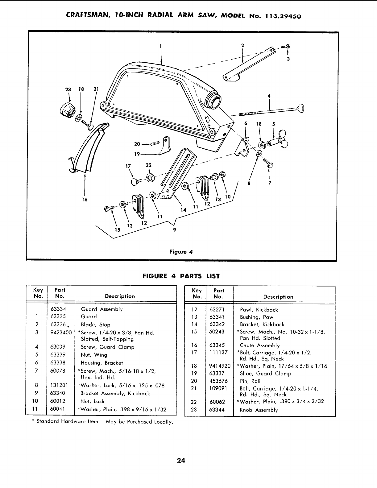
CRAFTSMAN, IO-INCH RADIAL ARM SAW, MODEL No. !13.29450
23 18 21
16
4
6 18 5
J
J
17 22
,!oJ
8 7
Figure 4
FIGURE 4
Key Part
No. No. Description
63334
I 63335
2 63336.
3 9423400
4
5
6
7
63039
63339
63338
60078
8 131201
9 63340
10 60012
11 60041
Guard Assembly
Guard
Blade, Stop
*Screw, 1/4-20 x 3/8, Pan Hd.
Slotted, Self-Tapping
Screw, Guard Clamp
Nut, Wing
Housing, Bracket
*Screw, Mach., 5/16-18 x 1/2,
Hex. Ind. Hd.
*Washer, Lock, 5/16x .125 x .078
Bracket Assembly, Kickback
Nut, Lock
*Washer, Plain, .198 x 9/16 x 1/32
* Standard Hardware Item May be Purchased Locally.
PARTS LIST
Key Part
No. No. Description
12 63271
13 63341
14 63342
15 60243
16
17
18
19
20
21
22
23
63345
111137
9414920
63337
453676
109091
60062
63344
Pawl, Kickback
Bushing, Pawl
Bracket, Kickback
*Screw, Mach., No. 10-32x1-1/8,
Pan Hd. Slotted
Chute Assembly
*Bolt, Carriage, 1/4-20 x 1/2,
Rd. Hd., Sq. Neck
*Washer, Plain, 17/64 x 5/8 x 1/16
Shoe, Guard Clamp
Pin, Roll
Bolt, Carriage, 1/4-20 x 1-1/4,
Rd. Hd., Sq. Neck
*Washer, Plain, .380 x 3/4 x 3/32
Knob Assembly
24
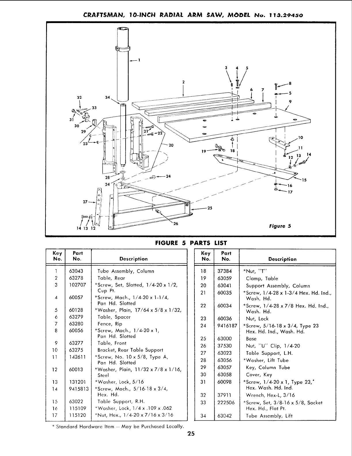
CRAFTSMAN, IO-IN_H RADtAL ARM SAW, MODI_L No. 11_.2945o
31
32
30
29
33
34
6 7
Figure 5
FIGURE 5 PARTS LIST
Key Part
No. No. Description
1
2
3
5
6
7
8
63043
63278
102707
60057
60128
63279
63280
60056
963277
10 63275
11 142611
12
13
14
15
16
17
60013
131201
9415813
63022
115109
115120
Tube Assembly, Column
Table, Rear
*Screw, Set, Slotted, 1/4-20 x 1/2,
Cup Pt.
*Screw, Mach., 1/4-20 x 1-1/4,
Pan Hd. Slotted
*Washer, Plain, 17/64 x 5/8 x 1/32,
Table, Spacer
Fence, Rip
*Screw, Mach., 1/4-20 x 1,
Pan Hd. Slotted
Table, Front
Bracket, Rear Table Support
*Screw, No. 10 x 5/8, Type A,
Pan Hd. Slotted
*Washer, Plain, 11/32 x 7/8 x 1/16,
Steel
*Washer, Lock, 5/16
*Screw, Mach., 5/16-18 x 3/4,
Hex. Hd.
Table Support, R.H.
*Washer, Lock, 1/4 x .109 x .062
*Nut, Hex., 1/4-20 x 7/16 x 3/16
Key Part
No. No. Description
18 37384
19 63059
20 63041
21 60035
22
23
24
25
26
27
28
29
30
31
32
33
34
60034
60036
9416187
63000
37530
63023
63056
63057
63058
60098
37911
222506
63042
*Nut, "'T"
Clamp, Table
Support Assembly, Column
*Screw, 1/4-28 x 1-3/4 Hex. Hd. Ind.,
Wash. Hd.
*Screw, 1/4-28 x 7/8 Hex. Hd. Ind.,
Wash. Hd.
Nut, Lock
*Screw, 5/16-18 x 3/4, Type 23
Hex. Hd. Ind., Wash. Hd.
Base
Nut, "U" Clip, 1/4-20
Table Support, L.H.
*Washer, Lift Tube
Key, Column Tube
Cover, Key
*Screw, 1/4-20 x 1, Type 23, °
Hex. Wash. Hd. Ind.
Wrench, Hex-L, 3/16
*Screw, Set, 3/8-16 x 5/8, Socket
Hex. Hd., Flat Pt.
Tube Assembly, Lift
* Standard Hardware Item May be Purchased Locally.
25
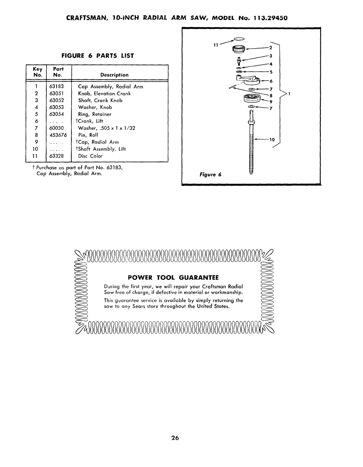
CRAFTSMAN, 10-|NCH RADIAL ARM SAW, MODEL No. 1 I;3.29o,50
FIGURE 6 PARTS LIST
Key Part
No. No. Description
1 63183
2 63051
363052
4 63053
5 63054
6 ....
7 60030
8 453676
9 .....
10 .....
11 63328
Cap Assembly, Radial Arm
Knob, Elevation Crank
Shaft, Crank Knob
Washer, Knob
Ring, Retainer
tCrank, Lift
Washer, .505 x 1 x 1/32
Pin, Roll
tCap, Radial Arm
tShaft Assembly, Lift
Disc Color
t Purchase as part of Pan' No. 63183,
Cap Assembly, Radial Arm. Figure 6
11...._ _:_ ._
uring the, poir ay urCraftsman Radial
Saw free _rial or workmanship.
This guar__ able by simply re utrning the
saw to any Sears store throughout the United States.
26
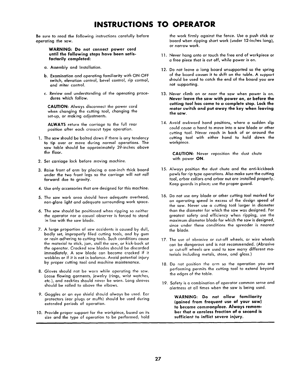
INSTRUCTIONS TO OPERATOR
Be sure to read the following instructions carefully before
operating the saw.
WARNING: Do not connect power cord
until the following steps have been satis-
factorily completed:
a. Assembly and Installation.
b. Examination and operating familiarity with ON-OFF
switch, elevation control, bevel control, rip control,
and miter control.
c. Review and understanding of the operating proce-
dures which follow.
CAUTION: Always disconnect the power cord
when changing the cutting tool, changing the
set-up, or making adjustments.
ALWAYS return the carriage to the full rear
position after each crosscut type operation.
1. The saw should be bolted down if there is any tendency
to tip over or move during normal operations. The
saw table should be approximately 39-inches above
the floor.
2. Set carriage lock before moving machine.
3. Raise front of arm by placing a one-inch thick board
under the two front legs so the carriage will not roll
forward due to gravity.
4. Use only accessories that are designed for this machine.
5. The saw work area should have adequate overhead,
non-glare Jight and adequate surrounding work space.
6. The saw should be positioned when ripping so neither
the operator nor a casual observer is forced to stand
in line with the saw blade.
7. A large proportion of saw accidents is caused by dull,
badly set, improperly filed cutting tools, and by gum
or resin adhering to cutting tools. Such conditions cause
the material to stick, jam, stall the saw, or kick-back at
the operator. Cracked saw blades should be discarded
immediately. A saw blade can become cracked if it
wobbles or if it is not in balance. Avoid potential injury
by proper cutting tool and machine maintenance.
8. Gloves should not be worn while operating the saw.
Loose flowing garments, jewelry (rings, wrist watches,
etc_/, and neckties should never be worn. Long sleeves
should be rolled to above the elbows.
9. Goggles or an eye shield should always be used. Ear
protectors (ear plugs or muffs) should be used during
extended periods of operation.
10. Provide proper support for the workpiece, based on its
size and the type of operation to be performed; hold
11.
12.
13.
14.
15.
16.
17.
18.
19.
the work firmly against the fence. Use a push stick or
board when ripping short work (under 12-inches long),
or narrow work.
Never hang onto or touch the free end of workpiece or
a free piece that is cut off, while power is on.
Do not leave a long board unsupported so the spring
of the board causes it to shift on the table. A support
should be used to catch the end of the board you are
not supporting.
Never climb on or near the saw when power is on.
Never leave the saw with power on, or before the
cutting tool has come to a complete stop. Lock the
motor switch and put away the key when leaving
the saw.
Avoid awkward hand positions, where a sudden slip
could cause a hand to move into a saw blade or other
cutting tool. Never reach in back of or around the
cutting tool with either hand to hold down the
workpiece.
CAUTION: Never reposition the dust chute
with power ON.
Always position the dust chute and the anti-kickback
pawls for rip type operations. Also make sure the cutting
tool, arbor collars and arbor nut are installed properly;
Keep guards in place; use the proper guard.
Do not use any blade or other cutting tool marked for
an operating speed in excess of the design speed of
the saw. Never use a cutting tool larger in diameter
than the diameter for which the saw was designed. For
greatest safety and efficiency when ripping, use the
maximum diameter blade for which the saw is designed,
since under these conditions the spreader is nearest
the blade.
The use of abrasive or cut-off wheels, or wire wheels
can be dangerous and is not recommended. (Abrasive
or cut-off wheels are used to saw many different ma-
terials including metals, stone, and glass.)
Do not position the arm so the operation you are
performing permits the cutting tool to extend beyond
the edges of the table.
Safety is a combination of operator common sense and
alertness at all times when the saw is being used.
WARNING: Do not allow familiarity
(gained from frequent use of your saw)
to become commonplace. Always remem-
ber that a careless fraction of a second is
sufficient to inflict severe injury.
27
SeaFs owners manuaJ
MODEL No.
113.29450
HOW TO ORDER
REPAIR PARTS
SEARS SERVICE
IS AT YOUR SERVICE
WHEREVER YOU LIVE
OR MOVE IN THE U.S.A.
The Model Number will be found on a plate attached to your
saw, at the left side of the base. Always mention the Model
Number when requesting service or repair parts for your
10-INCH RADIAL ARM SAW.
All parts listed herein may be ordered through SEARS, ROEBUCK
AND CO. or SIMPSONS-SEARS LIMITED. When ordering parts
by mail, selling prices will be furnished on request or parts will be
shipped at prevailing prices and you will be billed accordingly.
WHEN ORDERING REPAIR PARTS, ALWAYS GIVE THE
FOLLOWING INFORMATION AS SHOWN IN THIS LIST.
1. The PART NUMBER
3. The MODEL NUMBER
113.29450
2. The PART DESCRIPTION
4. The NAME of ITEM -- 10-INCH
RADIAL ARM SAW
Your Sears merchandise takes on added value when you
discover that Sears has over 2,000 Service Units throughout
the country. Each is staffed by Sears-trained, professional
technicians using Sears approved parts and methods.
Form No. 3_i98 4 5/73
