Sears 536 25587 Users Manual
536255870 536255870 CRAFTSMAN LAWN TRACTOR - Manuals and Guides L0909097 View the owners manual for your CRAFTSMAN LAWN TRACTOR #536255870. Home:Lawn & Garden Parts:Craftsman Parts:Craftsman LAWN TRACTOR Manual
CRAFTSMAN Lawn, Tractor Manual L0909097 CRAFTSMAN Lawn, Tractor Owner's Manual, CRAFTSMAN Lawn, Tractor installation guides
!! Sears-11 Sears Lawn Mower Manuals - Lawn Mower Manuals – The Best Lawn Mower Manuals Collection
536.25587 to the manual d031fa86-2f30-4dc7-8cad-7db9aac570f9
2015-02-05
: Sears Sears-536-25587-Users-Manual-399143 sears-536-25587-users-manual-399143 sears pdf
Open the PDF directly: View PDF ![]() .
.
Page Count: 74
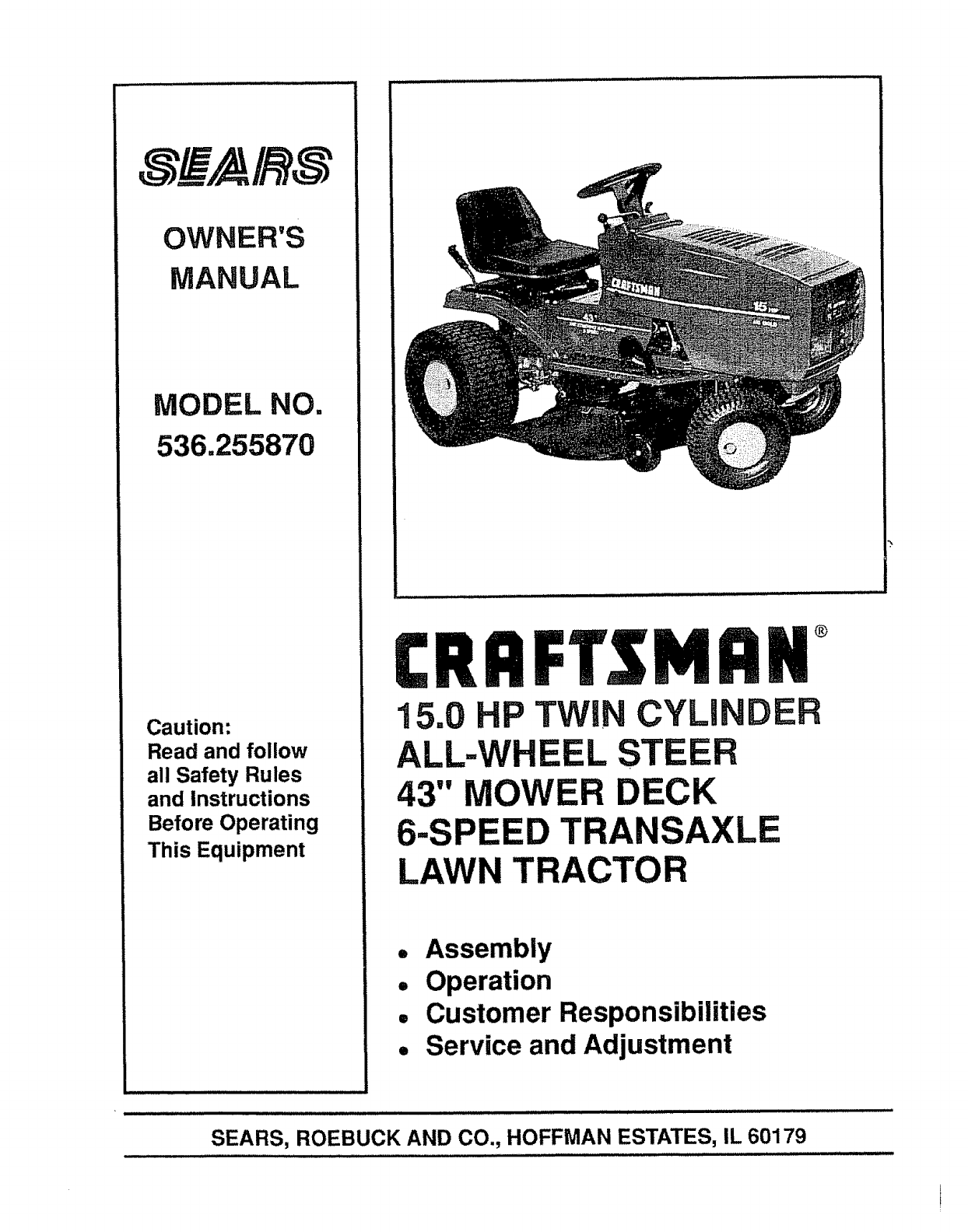
OWNER'S
MANUAL
MODEL NO.
536.255870
Caution:
Read and follow
all Safety Rules
and Instructions
Before Operating
This Equipment
CRRFTSMRN°
15.0 HP TWiN CYLI
ALL=WHEEL
43" MOWER DECK
6-SPEED TRANSAXLE
LAWN TRACTOR
R
o Assembly
°Operation
° Customer Responsibilities
° Service and Adjustment
SEARS, ROEBUCK AND CO., HOFFMAN ESTATES, IL 60179
s .0LEa AITHESE INSTRUCTIONS ABE FOR YOUR PROTECTtON_ PLEASE READ THEM CAREFU LLY=
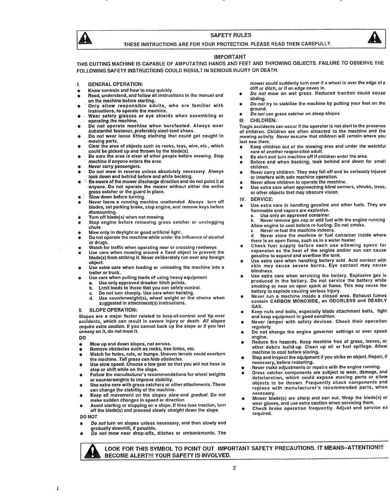
IMPORTANT
THIS CUTTING MACHINE IS CAPABLE OF AMPUTATING HANDS AND FEET AND THROWING OBJECTS=. FAILURE TO OBSERVE THE
FOLLOWING SAFETY INSTRUCTIONS COULD RESULT IN SERIOUS iNJURY OR DEATH°
l. GENERAL OPERATION:
e Know controls and how to stop quickly..
o Read, understand, and fotlQy_ atl instructions in the manual and
on the machine before starting.
• Only allow responsible adults, who are familiar with
Instructions, to operate the machine.
•-'Wear safety glasses or eye shields when assembling or
operating the machine.
Do not operate machine when barefooted. Always wear
,_ubstantial footwear, preferably steel*toed shoes.
e. Do not wear loose fitting clothing that could get caught in
.moving parts.
• Clear the area of objects such as rocks, toys, wire, etc., which
could be picked up and thrown by the blade(s).
• Be sure the area is clear of other people before mowing,. Stop
'machine if anyone enters the area,
eNever carry passengers.
e. Do not mow in reverse unless absolutely necessary., Always
'look down and behind before and while backing.
•:. Beaware of the mower discharge direction end do not point it at
.'anyone, Do not operate the mower without either the entire
grass catcher or the guard in place°
e Slow down before turning.
o Never leave arunning machine unattended. Always turn off
blades, set parking brake, stop engine, and remove keys before
dlsmounting_
e Turn off blade(s) when not mowing.
e Stop engine before removing grass catcher or unclogging
chute.
e Mow only in daylight or good artificial fight..
e Do not operate the machine whlte under the influence of alcohot
or drugs.
• Watch for traffic when operating near or crossing roadways.
• Use care when mowing around a fixed object to prevent the
blade(s) from strtkfng tt_ Never deliberately run over any foreign
.obJect,,
e Use extra care when loading or unloading the machine Into a
traf!er or truck,
e Use care when putl_ng loads of using heavy equipment
ao Useonly approved drawbar hitch points.,
b_ LImtt loads to those that you can safely control
€,. Do not turn sharply. Use care when backing,
d. Use counterweight(s), wheel weight or tire chains when
suggested in attachment(s) instructions,.
IL SLOPE OPERA1]ON:
Slopes are a major factor related to loss-of-control and tip-over
accidents, which can result in severe injury or death All slopes
require extra caution. I! you cannot back up the slope or if you feet
uneasy on It, do not mow it.
DO
e Mow up and down slopes, not across.
e Remove obstacles such as rocks, tree limbs, etc.
e Watch for holes, ruts, or bumps. Uneven terrain could overturn
the machine. Tall grass can hide obstacles.
• Usa slow speed. Choose a low gear so that you will not have to
stop or shift while on the slope=
e Follow the manufacturer*s recommendations for whee_ weights
or counterweights to improve stabt]ity_
eUse extra care with grass catchers or other attachments., These
can change the stability of the machfne,_
• Keep all movement on the slopes slow and gradual. Do not
make sudden changes in speed or direction.
•Avoid starting or stopping on a slope, If tires lose traction, turn
off the blade(s) and proceed slowty straight down the slope.
DO NOT
•Do not turn on stapes unless necessary, and then slowly and
gradually downhill, if possible_
•Do not mow near drop-oils, ditches or embankments., The
mower could suddenly turn over if awheel is over the edge of a
cliff or ditch, or if an edge caves in_
eDo not mow on wet grass. Reduced traction could cause
sliding.
•Do not try to stabilize the machine by putting your foot on the
ground.
•Do not use grass catcher on steep slopes
ill. CHILDREN:
Tragic accidents can occur if the operator Is not alert to the presence
of children, Children are often attracted to the machine and the
mowing activity Never assume that children will remain where you
last saw them_
a Keep children out of the mowing area and under the watchful
care of another responsible adult.,
e Be alert and turn machine off if children enter the area.
• Before and when backing, look behind and down for small
chtldreno
•Never carry chtldren_ 3"hey may fall off and be seriously injured
or interfere with safe machine operation.
• Never allow children to operate the machine.
•Use extra care when approaching blind corners, shrubs, trees,
or other objects that may obscure vision.
IV., SERVICE:
eUse extra care in handilng gasoline and other fuels. They are
flammable and vapors are explosive.
mUse only an approved container,
b Never remove gas cap or add fuel with the engine running
Altow engine to cool before re*fueling. Do not smoker
c. Never ro-fue_ the machine indoors..
d_ Never store the machine or fuel container inside where
there is an open flame, such as in a water heater,
eCheck fuel supply before each use allowing space for
expansion as the heat of the engine andlor sun can cause
gasoline to expand and ovedtow the tank.,
eUse extra care when handling battery acid. Acid contact wlth
skin may cause severe burns_ Eye contact may cause
blindness,
e Use extra care when servtcLng the battery_ Explosive gas is
produced in the battety_ Do not service the battery while
smoking or near an open spark or flame_ This may cause the
battery to explode causing serious Injury,
e Never run a machine inside a closed area. Exhaust fumes
contain CARBON MONOXIDE, an ODORLESS and DEADLY
GAS.
a Keep nuts and bolts, especially blade attachment bolts, tight
and keep equipment in good condition=
e Never tamper with safety devices., Check their operation
regularly.,
• Do not change the engine governor settings or over speed
engine.
e Reduce fire hazards. Keep machine free of grass, leaves, or
other debris build-up Clean up otl or fuel spillage° Allow
machine to cool before storing,
• Stop and inspect the equipment if you strike an object., Repair, if
necessary, before restartfng.
•Never make adjustments or repairs with the engine running°
eGrass catcher components are subject to wear, damage, and
deterioration, which could expose moving parts or allow
objects to be thrown.. Frequently check components and
replace with manufacturer's recommended parts, when
necessary_
• Mower blade(s) are sharp and can cuL Wrap the blade(s) or
wear gioves, and use extra caution when servicing them..
eCheck brake operation frequently_ Adjust and service as
required,.
I A LOOK FOR THIS SYMBOL TO POINT OUT IMPORTANT SAFETY PRECAUTIONS,, IT MEANS--ATTENTION!!!
BECOME ALERT!!! YOUR SAFETY IS INVOLVED.
2

CONGRATULATIONSon yourpurchaseof a Sears
CraftsmanTractor.It hasbeendesigned,engineered
andmanufacturedtogiveyouthebestpossibledepend-
abilityandperformance.
Shouldyouexperienceanyproblemyoucannoteasily
remedy,pleasecontactyournearestSearsService
CenterlDepartment.Wehavecompetent,well-trained
techniciansandthepropertoolstoserviceorrepairthis
unit,,
Pleasereadandretainthismanual.Theinstructionswill
enableyouto assembleand maintainyourtractor
properlyAlwaysobservethe"SAFETYRULES.,"
MODEL
NUMBER536255870
SERIAL
NUMBER
DATEOF
PURCHASE
THEMODELANDSERIALNUMBERSWILLBE
FOUNDONAPLATEUNDERTHESEAT_
YOUSHOULDRECORDBOTHSERIALNUMBER
ANDDATEOFPURCHASEANDKEEPINASAFE
PLACEFORFUTUREREFERENCE.
MAINTENANCE AGREEMENT
A Sears Maintenance Agreement is available on this
product.. Contact your nearest Sears Store for details.
CUSTOMER RESPONSIBILITIES
•Read and observe safety rules,
e Follow a regular schedule in maintaining, caring for and
using your unit.,
o Follow the instructions under "Customer Responsi-
bilities" and "Storage" sections of this manual,
PRODUCT SPECIFICATIONS
HORSE POWER:
GASOLINE
CAPACITY:
OIL (3,,0 Pints)
SPARK PLUG :
VALVE
CLEARANCE:
GROUND
SCEED:
TIRE PRESSURE:
CHARGING SYSTEM:
BLADE BOLT TORQUE:
15.0
2GALLONS
UNLEADED REGULAR
SAE 30 - above 32°F,
5W -30" - below 32°F_
Champion RJ19LM
(GAP ,030 in.)
Intake: ,004 -,006 in,
Exhaust: ,007- ,009 in,
FORWARD
1st 122
2nd 251
3rd 3,21
4th 3°79
5th 4.,76
6th 592
REVERSE: 2,70
FRONT: 14 PSf
REAR: 10 PSI
2,4 AMPS @ 3300 RPM
30-35 FT, LBS,,
MPH
MPH
MPH
MPH
MPH
MPH
MPH
WARNING: This unit is equipped with an internal com-
bustion engine and should not be used on or near any
unimproved forest-covered, brush-covered or grass-
covered land unless the engine's exhaust system is
equippedwith a spark arrester meeting applicable local
or state laws (if any)._If aspark arrester is used, it should
be maintained in effectiveworking order bythe operator.
In the state of California the above is required by law
(Section 4442 ofthe California PublicResources Code),
Other states may have similartaws,,Federal laws apply
on federal lands,, A spark arrester for the muffler is
available throughyour nearestSears Authorized Service
Center (See REPAIR PARTS section in this manual).
CRAFTSMAN ELECTRIC START RIDING EQUIPMENT
LIMITED TWO YEAR WARRANTY ON ELECTRIC START RIDING EQUIPMENT
For two (2) years from the date of purchase, if this riding equipment is maintained, lubricated and tuned-up according to the
instructions in the owner's manual, Sears will repair or replace, any parts found to be defective in material or workmanship
This warranty does not cover:
• Expendable items which become worn during normal use, such as blades, spark plugs, air cleaners and belts..
• Tire replacement or repair caused by punctures from outside objects, such as nails, thorns, stumps, or glass.
=Repairs necessary because of operator abuse, negligence, improper storage or accident or the failure to maintainthe
equipment according to the instructionscontained in the operator'smanual.
•Ridingequipment used for commercial or rental purposes..
LIMITED 90 DAY WARRANTY ON BATTERY
For 90 days from the date of purchase, if any battery included with this riding equipment proves defective in material or
workmanship and our testing determines the battery' wilt not hold a charge, Sears will replace the battery at no charge,.
WARRANTY SERVICE IS AVAILABLE BY RETURNING THE RIDING EQUIPMENT TO THE NEAREST SEARS SERVICE
CENTERIDEPARTMENT IN THE UNITED STATES
This warranty gives you specific legal rights, and you may also have other rights which may vary from state to
state.
SEARS, ROEBUCK AND CO., D/817WA, HOFFMAN ESTATES, IL 60179
3
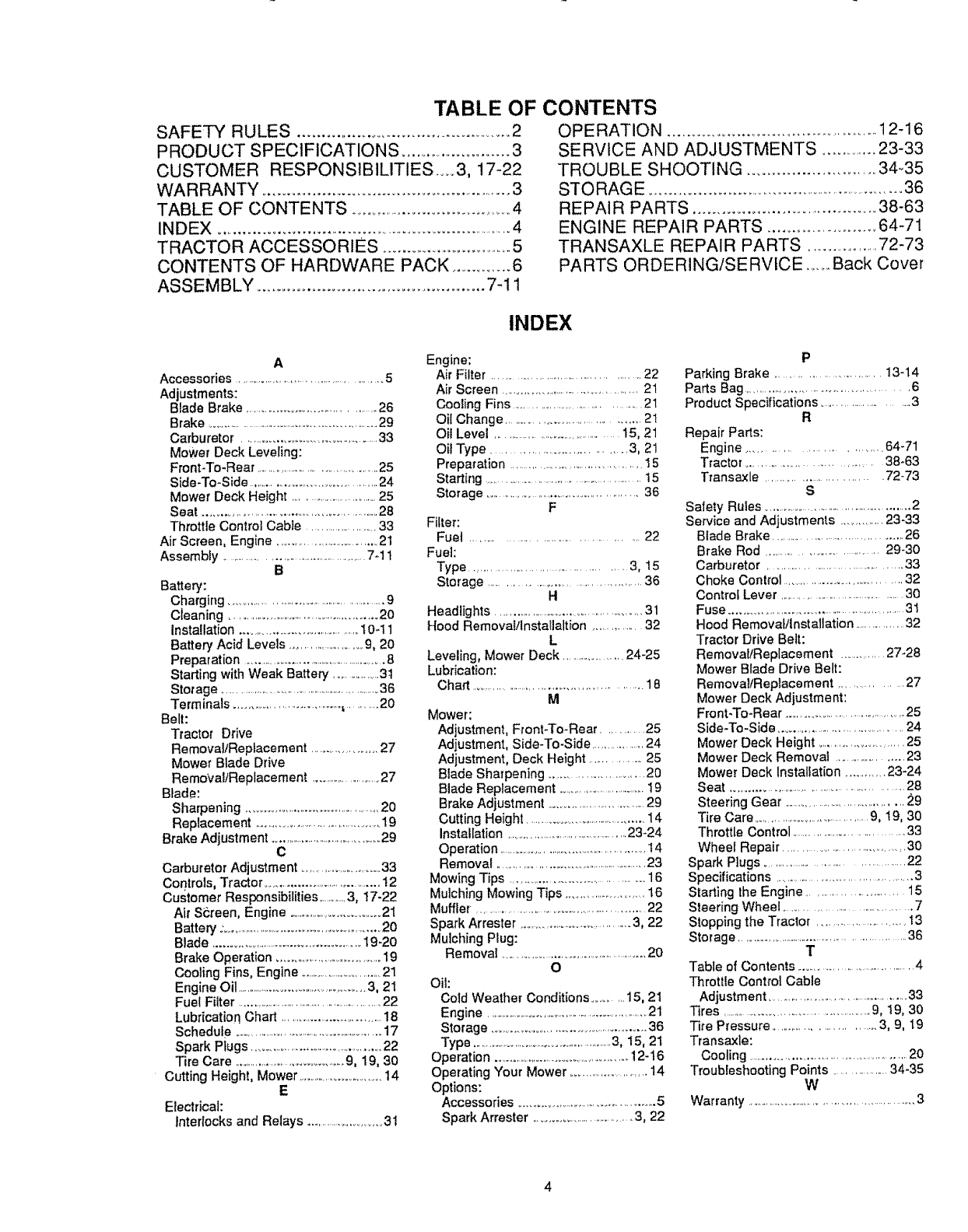
TABLE OF CONTENTS
SAFETY RULES ................................................... 2
PRODUCT SPECIFICATIONS ........................... 3
CUSTOMER RESPONSIBILITIES .....3, 17-22
WARRANTY ........................................................... 3
TABLE OF CONTENTS ..........................................4
INDEX ......................................................................... 4
TRACTOR ACCESSORIES ............................... 5
CONTENTS OF HARDWARE PACK ............... 6
ASSEMBLY ............................................... 7-! !
OPERATION .................................................. 12-16
SERVICE AND ADJUSTMENTS ..............23-33
TROUBLE SHOOTING .......................... 34-35
STORAGE ........................................................................36
REPAIR PARTS ...................................... 38-63
ENGINE REPAIR PARTS ......................... 64-71
TRANSAXLE REPAIR PARTS ................. 72-73
PARTS ORDERING/SE RVlCE ...... Back Cover
INDEX
A
Accessories ............................................5
Adjustments:
Blade Brake .............................................26
Brake ...........................................................29
Carburetor ..........................................33
Mower Deck Leveling:
Fmnt:l'o-Rear .........................................25
Side-To-Side ........................................24
Mower Deck Height .................................25
Seat ......................................................28
Throttle Control Cable ...................33
Air Screen, Engine ................................21
Assembly ....................................................7-1 t
B
Battery:
Charging ...................................................9
Cleaning ....................................................20
Installation .........................................10-11
Battery Acid Levels ..........................9, 20
Preparation ........................................................8
Starting with Weak Battery ....................31
Storage .................................................................36
Term inals ..................................._.........20
Belt:
Tractor Drive
Removal/Replacement .....................27
Mower Blade Drive
RemovaltReplacement ........................27
Blade:
Sharpening .............................................20
Replacement .............................................19
Brake Adjustment ........................................29
C
Carburetor Adjustment ...............................33
Controls, Tractor..........................................12
Customer Responsibilities..............3, 17-22
Air Screen, Engine ..............................21
Battery :........................................................20
Blade ...................................................19-20
Brake Operation .....................................19
Cooling Fins, Engine ...................................21
Engine Oil ...................................................3, 2I
Fuel Filter .....................................................22
Lubrication Chart .....................................18
Schedule ...........................................................17
Spark Plugs ................................................22
Tire Care ...........................................9, 19, 30
Cutting Height, Mower ..........................14
E
Electrical:
interlocks and Relays ..............................3t
Engine:
Air Filter .............................................22
Air Screen ..........................................21
Cooling Fins ..........................................21
Oil Change ....................................... 21
Oil Level ......................................15, 21
Oil Type ................................ 3, 21
Preparation .............................................15
Starting ....................................................t5
Storage ............................................. 36
F
Filter:
Fuel .......................................... 22
Fuel:
Type ........................................... 3, 15
Storage ..............................................36
H
Headlights .....................................................31
Hood Removai!lnstal]altion .............. 32
L
Leveling, Mower Deck ....................24-25
Lubrication:
Chart ..........................................................18
M
Mower:
Adjustment, Front-To-Rear .............25
Adjustment, Side-To-Side ................24
Adjustment, Deck Height .................25
Blade Sharpening ............................20
Blade Replacement ......................................19
Brake Adjustment ...............................29
Cutting Height ........................................14
installation ..............................................23-24
Operation ......................................................14
Removal ..........................................................23
Mowing Tips .........................................16
Mulching Mowing Tips .............................16
Muffler _....................................................22
Spark Arrester ..........................................3, 22
Mulching Plug:
Removal ..................................................20
O
Oil:
Cotd Weather Conditions ........ 15, 21
Engine ...............................................................21
Storage .................................................36
Type ...........................................................3, 15, 21
Operation ....................................................12-16
Operating Your Mower ..........................14
Options:
Accessories ................................................5
Spark Arrester ................................3, 22
P
Parking Brake ............................... 13-14
Parts Bag ............................................... 6
Product Specifications ............................3
R
Repair Parts:
Engine ............................... 64-71
Tractor ................................ 38-63
Transaxle .............................. 72-73
S
Safety Rules .................................................2
Service and Adjustments .............23-33
Blade Brake ..........................................26
Brake Rod ................................ 29-30
Carburetor ..........................................33
Choke Control ................................. 32
Control Lever .............................................30
Fuse ..........................................................31
Hood Removal/Installation ..................32
Tractor Drive Belt:
Removal/Replacement .............27-28
Mower Blade Drive Belt:
Removal/Replacement .................. 27
Mower Deck Adjustment:
Front-To-Rear .......................................25
Side-To-Side ........................................24
Mower Deck Height ..........................25
Mower Deck Removal .......................23
Mower Deck Installation ........... 23-24
Seat ......................................................28
Steering Gear .........................................29
Tire Care .......................................9, ! 9, 30
Throttle Control ....................................33
Wheel Repair ....................................30
Spark Plugs .............................................22
Specifications ..............................................3
Starting the Engine .......................... 15
Steering Wheel .........................................7
Stopping the Tractor .......................... 13
Storage ..............................................................36
T
Table of Contents .........................................4
Throttle Control Cable
Adjustment ..................................................33
Tires .................................................9, t9, 30
Tire Pressure ...............................3, 9, 19
Transaxle:
Cooling ..................................................20
Troubleshooting Points .................34-35
W
Warranty ...........................................................3
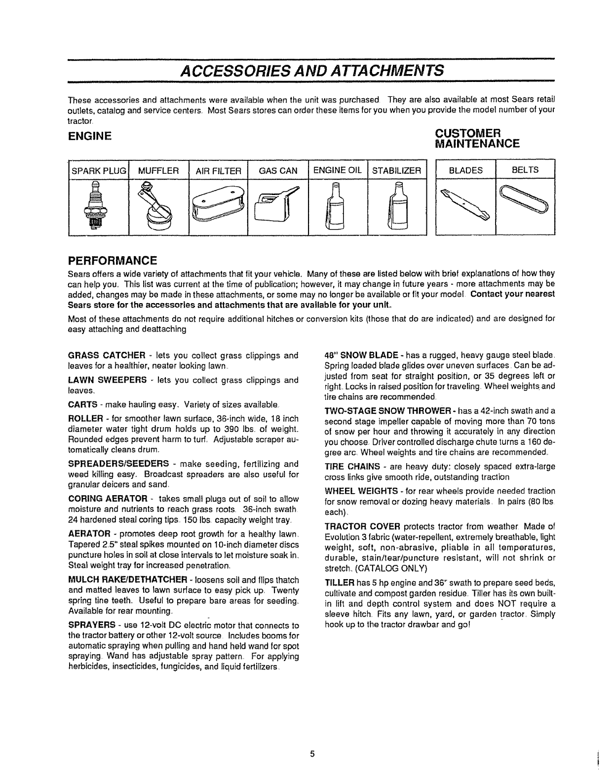
A CCESSORIES AND ATTACHMENTS
These accessories and attachments were available when the unit was purchased They are also available at most Sears retaiJ
outlets, catalog and service centers, Most Sears stores can order these items for you when you provide the model number of your
tractor.
ENGINE CUSTOMER
MAINTENANCE
SPARK PLUG MUFFLER AiR FILTER BELTSGAS CAN ENGINE OIL STABILIZER BLADES
PERFORMANCE
Sears offers awide variety of attachments that fit your vehicle_ Many of these are listed below with brief explanations of how they
can help you.. This list was current at the time of publication;however, it may change in future years - more attachments may be
added, changes may be made in these attachments, or some may no longer be available or lit your model Contact your nearest
Sears store for the accessories and attachments that are available for your unit.
Most of these attachments do not require additional hitches or conversion kits (those that do are indicated) and are designed for
easy attaching and deattaching
GRASS CATCHER .. lets you collect grass c_ippings and
leaves for a healthier, neater looking lawn.
LAWN SWEEPERS - lets you collect grass clippings and
leaves.
CARTS - make hauling easy.. Variety of sizes available
ROLLER - for smoother lawn surface, 36-inch wide, 18 inch
diameter water tight drum holds up to 390 lbs of weight..
Rounded edges prevent harm to tuff. Adjustable scraper au-
tomatically cleans drum.
SPREADERSiSEEDERS - make seeding, fertilizing and
weed killing easy. Broadcast spreaders are also useful for
granular deicers and sand.
CORING AERATOR - takes small plugs out of soil to allow
moisture and nutrients to reach grass roots. 36-inch swath
24 hardened steal coring tips. 150 Ibs. capacity weight tray
AERATOR - promotes deep root growth for a healthy lawn_
Tapered 25" steal spikes mounted on 10-inch diameter discs
puncture holes insoif at close intervals to let moisture soak in..
Steal weight tray for increased penetration..
MULCH RAKE!DE]HATCHER - loosens soil and flips thatch
and matted leaves to lawn surface to easy pick up, Twenty
spring tine teeth.. Useful to prepare bare areas for seeding°
Available for rear mounting.
SPRAYERS - use 12-volt DC electric motor that connects to
the tractor battery or other 12-volt source Includes booms for
automatic spraying when pullingand hand held wand for spot
spraying Wand has adjustable spray pattern. For applying
herbicides, insecticides,fungicides, and liquid fertilizers.
48" SNOW BLADE - has a rugged, heavy gauge steel blade.
Spring loaded blade glides over uneven surfaces. Can be ad-
justed from seat for straight position, or 35 degrees left or
right..Locks in raised position for traveling. Wheel weights and
tire chains are recommended.
TWO-STAGE SNOW THROWER -has a 42-inch swath and a
second stage impetler capable of moving more than 70 tons
of snow per hour and throwing it accurately in any direction
you choose Driver controlled discharge chute turns a 160 de-
gree arc Wheel weights and tire chains are recommended,.
TIRE CHAINS - are heavy duty: closely spaced extra-large
cross tinks give smooth ride, outstanding traction
WHEEL WEIGHTS - for rear wheels provide needed traction
for snow removal or dozing heavy materials. In pairs (80 Ibs
each).
TRACTOR COVER protects tractor from weather Made of
Evolution 3 fabric (water-repellent, extremely breathable, light
weight, soft, non-abrasive, pliable in all temperatures,
durable, stain/tear/puncture resistant, wil! not shrink or
stretch.. (CATALOG ONLY)
TILLER has 5 hp engine and 36" swath to prepare seed beds,
cultivate and compost garden residue. Tiller has its own built-
in lift and depth control system and does NOT require a
sleeve hitch. Fits any lawn, yard, or garden tractor. Simply
hook up to the tractor drawbar and go!
................................CONTENTS OF HARDWARE PACK
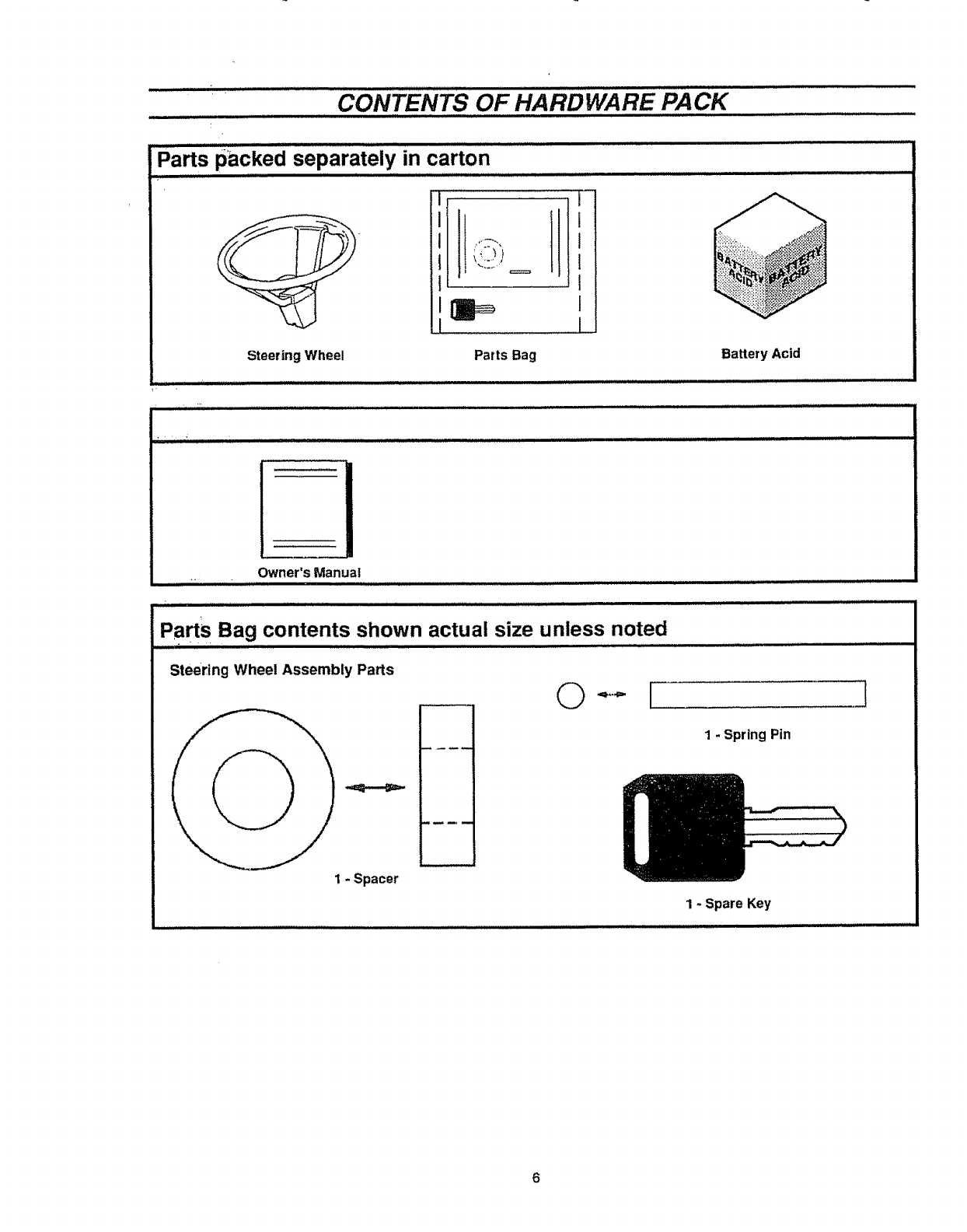
Parts packed separately in carton
i
_h:._,t I
i
Steering Wheel Parts Bag Battery Acid
Owner's Manual
Parts Bag contents shown actual size unless noted
Steering Wheel Assembly Parts
\
1 - Spacer
©[]
1 - Spring Pin
1 - Spare Key
ASSEMBL Y
TOOLS REQUIRED FOR ASSEMBLY
A socket wrench wilt make assembly easier. Standard wrench
sizes are listed
3/8 inch wrench
(1)
(1)
(I)
(1)
(1)
Pliers
Utility knife
Screwdriver (Small Phillips with a 1/4 inch shank)
Hammer
(1) Tire pressure gauge
(2) 7t16 inch wrenches
(1) 9!16 inch wrench
(1) Tape measure
When right and left hand is mentioned in this manual, it
means when you are in the operating position (seated behind
the steering wheel).
TO REMOVE TRACTOR FROM
CARTON
UNPACK CARTON
•Open top flaps,, Remove cardboard from top of wood
crate,
IMPORTANT: FOR SHIPPING PURPOSES THE MOWER
DECK WAS NOT ASSEMBLED ON TRACTOR. THE
MOWER DECK IS ATTACHED TO TOP FRAME AND SIDE
PANEL OF CARTON WHEN REMOVING MOWER DECK
FROM CARTON, MAKE SURE IT DOES NOT TOUCH
TRACTOR,
e
o
e
o
o
o
o
o
o
Using a 3/8" wrench, remove bolt that secures mower
deck hitch to top frame intop of carton
Remove top frame from carton
Carefully remove contents of parts box (see CONTENTS
OF HARDWARE PACK on page 6).
Cut down corners of side panel across from mower deck
with a utility knife and lay side panel down
Hold side panel (with mower deck attached) upright and
cut down corners,
Carefully lower side panel with mower deck,,
Lay down end panels of carton and discard cardboard from
alongside tractor.
Remove bolt that secures mower deck to side panet of
carton with 3/8" wrench.
Remove mower deck from carton, Lay aside for
installation later, Remove cardboard from discharge
chute,
•Remove plastic wrap from seat and hood
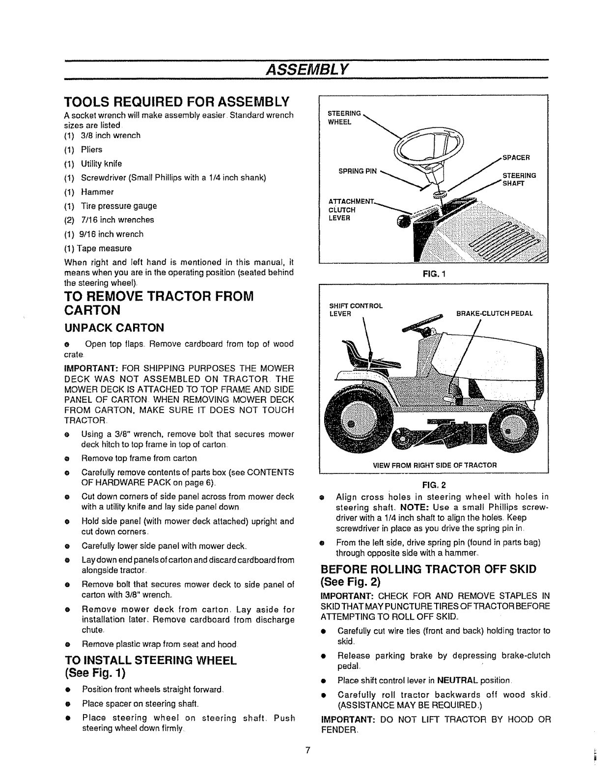
TO INSTALL STEERING WHEEL
(See Fig, 1)
•Position front wheels straight forward.
ePlace spacer on steering shaft,,
•Place steering wheel on steering
steering wheel down firmty
shaft, Push
STEERING
WHEEL
SPRING PIN
CLUTCH
LEVER
FIG. 1
SHIFT CONTROL
LEVER BRAKE, CLUTCH PEDAL
VIEW FROM RIGHT SIDE OF TRACTOR
FIG. 2
eAlign cross holes in steering wheel with holes in
steering shaft. NOTE: Use a small Phillips screw-
driver with a 1f4 inch shaft to align the holes, Keep
screwdriver in place as you drive the spring pin in,
•From the left side, drive spring pin (found in parts bag)
through opposite side with a hammer,,
BEFORE ROLLING TRACTOR OFF SKID
(See Fig. 2)
IMPORTANT: CHECK FOR AND REMOVE STAPLES IN
SKID THAT MAY PUNCTURE TIRES OF TRACTOR BEFORE
ATTEMPTING TO ROLL OFF SKID.,
•Carefully cut wire ties (front and back) holding tractor to
skid..
• Release parking brake by depressing brake-clulch
pedal,,
• Place shift control lever in NEUTRAL position.
• Carefully roll tractor backwards off wood skid,
(ASSISTANCE MAY BE REQUIRED,,)
IMPORTANT: DO NOT LIFT TRACTOR BY HOOD OR
FENDER,
7!
ASSEMBLY
HOW TO SET UP YOUR TRACTOR
PREPARE BATTERY
For shipping purposes, battery is installed, Remove battery
(see TO REMOVE BATTERY instructions below),
CAUTION: Wear eye and face shietd_
Wash hands or clothing immediately if
_-accidentally in contact with battery acid_
Do not smoke° Fumes from charged battery acid are
explosive°
Follow the CAUTIONS located on the battery° Al-
ways wear gloves, clothing and goggles to protect
your hands, skin and eyes.
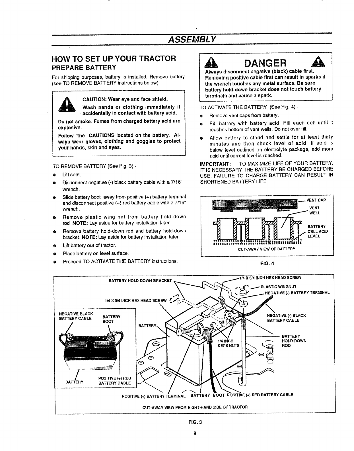
TO REMOVE BATTERY (See Fig 3) -
e Lift seal
• Disconnect negative (-) black battery cable with a 7It6"
wrench
eSlide battery boot away from positive (+) battery terminal
and disconnect positive (+) red battery cable with a 7t16"
wrench..
e Remove plastic wing nut from battery hold-down
rod NOTE: Lay aside for battery installation later
• Remove battery hold-down rod and battery hold-down
bracket. NOTE: Lay aside for battery installation later
• Lift battery out of tractor,.
e Place battery on level sufface=
e Proceed TO ACTIVATE THE BATTERY instructions
DANGER
Always disconnect negative (black) cable first.
Removing posltlve cable first can result In sparks if
the wrench touches any metal surface° Be sure
battery hold-down bracket does not touch battery
terminals and cause aspark.
TO ACTIVATE THE BATTERY (See Fig, 4) -
e Remove vent caps from battery,.
e Fill battery with battery acid, Fill each cell until it
reaches bottom of vent wells_ Do not over fill,.
OAllow battery to stand and settle for at least thirty
minutes and then check level of acid, if acid is
below level outlined on electrolyte package, add more
acid until correct level is reached,,
IMPORTANT: TO MAXIMIZE LIFE OF YOUR BATTERY,
1T IS NECESSARY THE BATTERY BE CHARGED BEFORE
USE, FAILURE TO CHARGE BATTERY CAN RESULT IN
SHORTENED BATTERY LIFE
VENT CAP
VENT
|1155:
CUT'AWAY ViEW OF BATTERY
BATTERY
CELL ACID
LEVEL
,=
FIG. 4
BATTERY HOLD-DOWN BRACKET ,
NEGATIVE BLACK
BATTERY CABLE
BATTERY
1/4 X3/4 INCH HEX HEAD SCREW
\
BAT_'ERY
BOOT
POSITIVE (+) RED
BATTERY CABLE
POSITIVE (+) BATTERY TERMINAL
X 3/4 INCH HEX HEAD SCREW
. NEGA3'IVE (-) BATTERY TERMINAL
NEGATIVE (-) BLACK
BATTERY CABLE
BATTERY
HOLD*DOWN
_ROD
BOOT POSITIVE (+) RED BATTERY CABLE
CLrr-AWAY VIEW FROM RIGHT-HAND SIDE OF TRACTOR
FIG. 3
ASSEMBL Y
CAUTION: Handle electrolyte with care°
It is an acid and poison. Always wear eye
shields, and protect skin when handling
acid or battery.
POISON -CAUSES SEVERE BURNS
Contains sulfuric acid,,
Avoid contact with skin, eyes or clothing°
To prevent accidents, neutralize excess acid with
baking soda and rinse empty container with water°
TREATMENT:
EXTERNAL - Flush with water.
INTERNAL -Drink large quantities of water or milk,.
Follow with milk of magnesia, beaten eggs or
vegetable oil Call physician immediately°
EYES - Flush with water for 15 minutes and get
prompt medical attention.
KEEP OUT OF THE REACH OF CHILDREN
e Charge battery at a rate of six (6) amps for t hour.
Use a 12-volt battery charger. Observe all safety
precautions required for battery charging Complete as-
sembly section of this manual while waiting for battery to
charge°
e Check acid level after the battery is charged_ If
acid has fallen below correct level, add distilled or iron
free water
eInstall vent caps to cover vent wells,. Wash top of battery
with water to remove any acid, then wipe dr#,,
e Check battery case for leakage to make sure that no
damage has occurred in handling,
eDispose of excess battery acid. Neutralize acid for dis-
posal by adding it to four inches of water in a five (5) gal-
lon plastic container Stir with a wooden or plastic paddle
while adding baking soda until the addition of more soda
causes no more foaming.
CHECK "TIRE PRESSURE
For shipping purposes, the tires on your tractor were over-in-
flated at the factory° Correct tire pressure is important ior best
cutting performance..
• Remove hub caps by placing two fingers in hole in each
cap and pulling them from the wheels..
e Use tire pressure gauge to check amount of air in tires.
• Reduce tire pressure to PSI shown in "PRODUCT
SPECIFICATIONS" on page 3 of this manual
e Replace hub caps. Position on wheels and push firmly
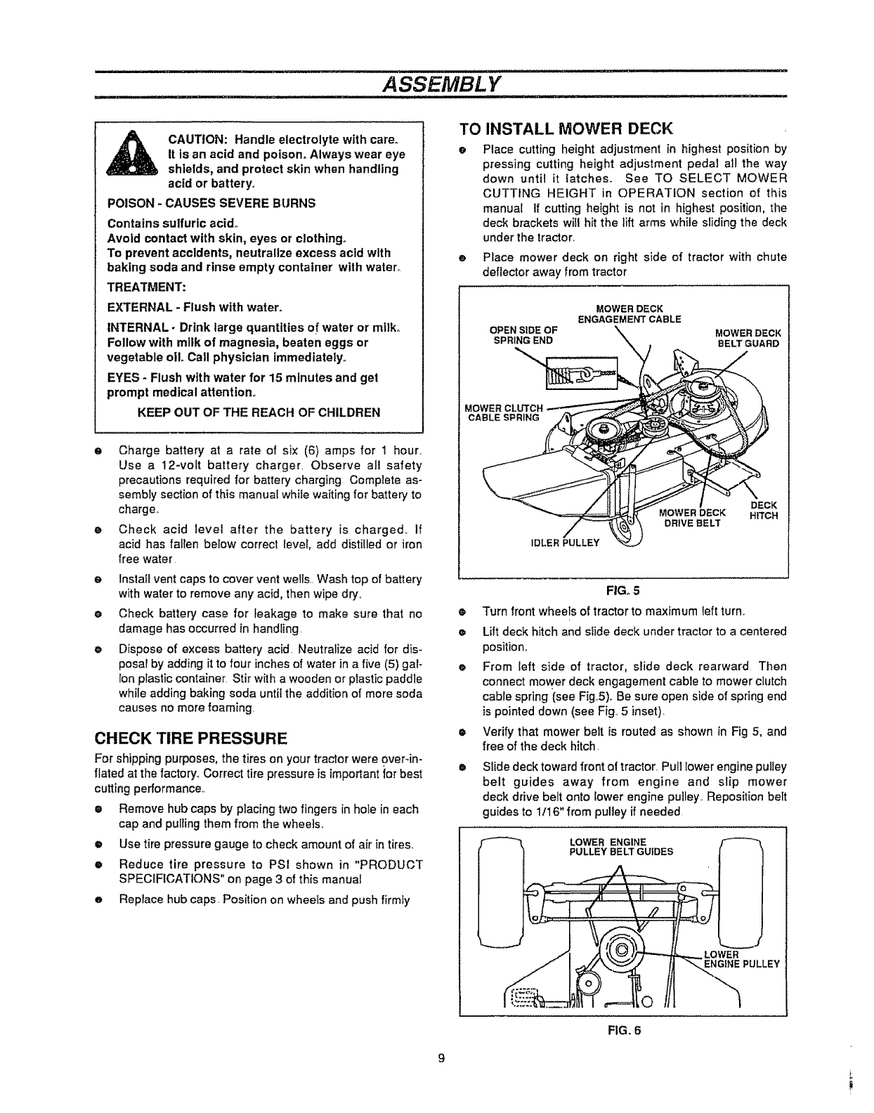
TO INSTALL MOWER DECK
e Place cutting height adjustment in highest position by
pressing cutting height adjustment pedal all the way
down until it latches. See TO SELECT MOWER
CUTTING HEIGHT in OPERATION section of this
manual 1f cutting height is not in highest position, the
deck brackets will hit the lift arms while sliding the deck
under the tractor,.
e Place mower deck on right side of tractor with chute
deflector away from tractor
MOWER DECK
ENGAGEMENT CABLE
OPEN SIDE OF _MOWER DECK
SPRING END \BELT GUARD
MOWER CLUTCH
CABLE SPRING
IDLER PULLE
MOWER DECK
DRIVE BELT
DECK
HITCH
O
o
FIG. 5
Turn front wheels of tractor to maximum left turn_.
Lift deck hitch and slide deck under tractor to acentered
position_
e From left side of tractor, slide deck rearward Then
connect mower deck engagement cable to mower clutch
cable spring (see Fig..5).Be sure open side of spring end
is pointed down (see Fig_ 5 inset),
• Verify that mower belt is routed as shown in Fig 5, and
free of the deck hitch.
• Slide deck toward front of tractor Pull lower engine pulley
belt guides away from engine and slip mower
deck drive belt onto lower engine pulley.. Reposition belt
guides to 1/16" from pulley if needed
LOWER ENGINE
PULLEY BELT GUIDES
LOWER
ENGINE PULLEY
FIG. 6
ASSEMBLY .......................................
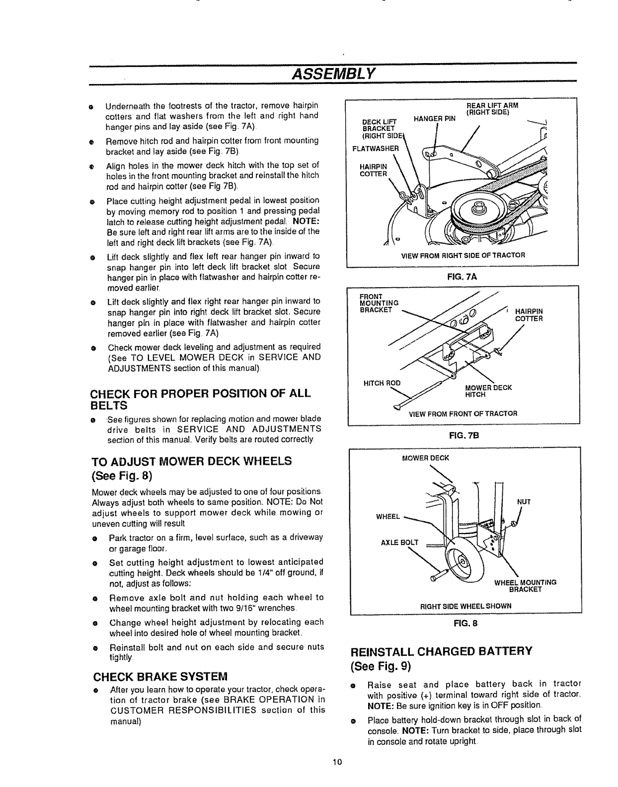
• Underneath the footrests of the tractor, remove hairpin
cotters and flat washers from the left and right hand
hanger pins and lay aside (see Fig. 7A)
•Remove hitch rod and hairpin cotter from front mounting
bracket and lay aside (see Fig 7B)
® Align holes in the mower deck hitch with the top set of
holes in the front mounting bracket and reinstall the hitch
rod and hairpin cotter (see Fig 7B),
e Place cutting height adjustment pedal in lowest position
by moving memory rod to position ! and pressing pedaf
latch to retease cutting height adjustment pedal NOTE:
Be sure left and right rear lift arms are to the inside of the
left and right deck lift brackets (see Fig,, 7A).
e Lift deck slightly and flex left rear hanger pin inward to
snap hanger pin into left deck lift bracket stot Secure
hanger pin in place with flatwasher and hairpin cotter re-
moved earlier,
eLift deck slightly and flex right rear hanger pin inward to
snap hanger pin into right deck lift bracket slot. Secure
hanger pin in place with flatwasher and hairpin cotter
removed earlier (see Fig. 7A)
eCheck mower deck leveling and adjustment as required
(See TO LEVEL MOWER DECK in SERVICE AND
ADJUSTMENTS section of this manual).
CHECK FOR PROPER POSITION OF ALL
BELTS
•.See figures shown for replacing motion and mower blade
drive belts in SERVICE AND ADJUSTMENTS
section of this manual Verify belts are routed correctly
TO ADJUST MOWER DECK WHEELS
(See Fig. 8)
Mower deck wheels may be adjusted to one of four positions
Always adjust both wheels to same position. NOTE: Do Not
adjust wheels to support mower deck while mowing or
uneven cutting will result
• Park tractor on a firm, level surface, such as a driveway
or garage floor._
eSet cutting height adjustment to lowest anticipated
cutting heighL Deck wheels should be 1/4" off ground, if
not, adjust as follows:
•Remove axle bolt and nut holding each wheel to
wheel mounting bracket with two 9It6" wrenches
eChange wheel height adjustment by relocating each
whee! into desired hole of wheel mounting bracket.
e Reinsta!l bolt and nut on each side and secure nuts
tightly.
CHECK BRAKE SYSTEM
•After you learn how to operate your tractor, check opera-
tion of tractor brake (see BRAKE OPERATION in
CUSTOMER RESPONSIBILITIES section of this
manual)
DECK LIFT
BRACKET
FLATWASHER
HAIRPIN \_
COTTE R
HANGER PIN
REAR LIFT ARM
(RIGHT SIDE)
FRONT
MOUNTING
BRACKET
VIEW FROM RIGHT SIDE OF TRACTOR
FIG,,7A
HAIRPIN
COTTER
H_TCHROD MOWER DECK
HITCH
VIEW FROM FROI_FrOF TRACTOR
FIG. 7B
MOWER DECK
WHEEL
NUT
AXLE BOLT
\
WHEELMOUNTING
BRACKET
RIGHT SIDEWHEELBHOWN
FIG, 8
REINSTALL CHARGED BATTERY
(See Fig. 9)
•Raise seat and place battery back in tractor
with positive (+) terminal toward right side of tractor..
NOTE: Be sure ignition key is in OFF position.
•Place battery hold-down bracket through slot in back of
console. NOTE: Turn bracket to side, pface throughslot
inconsole and rotate upright
10
ASSEMBLY
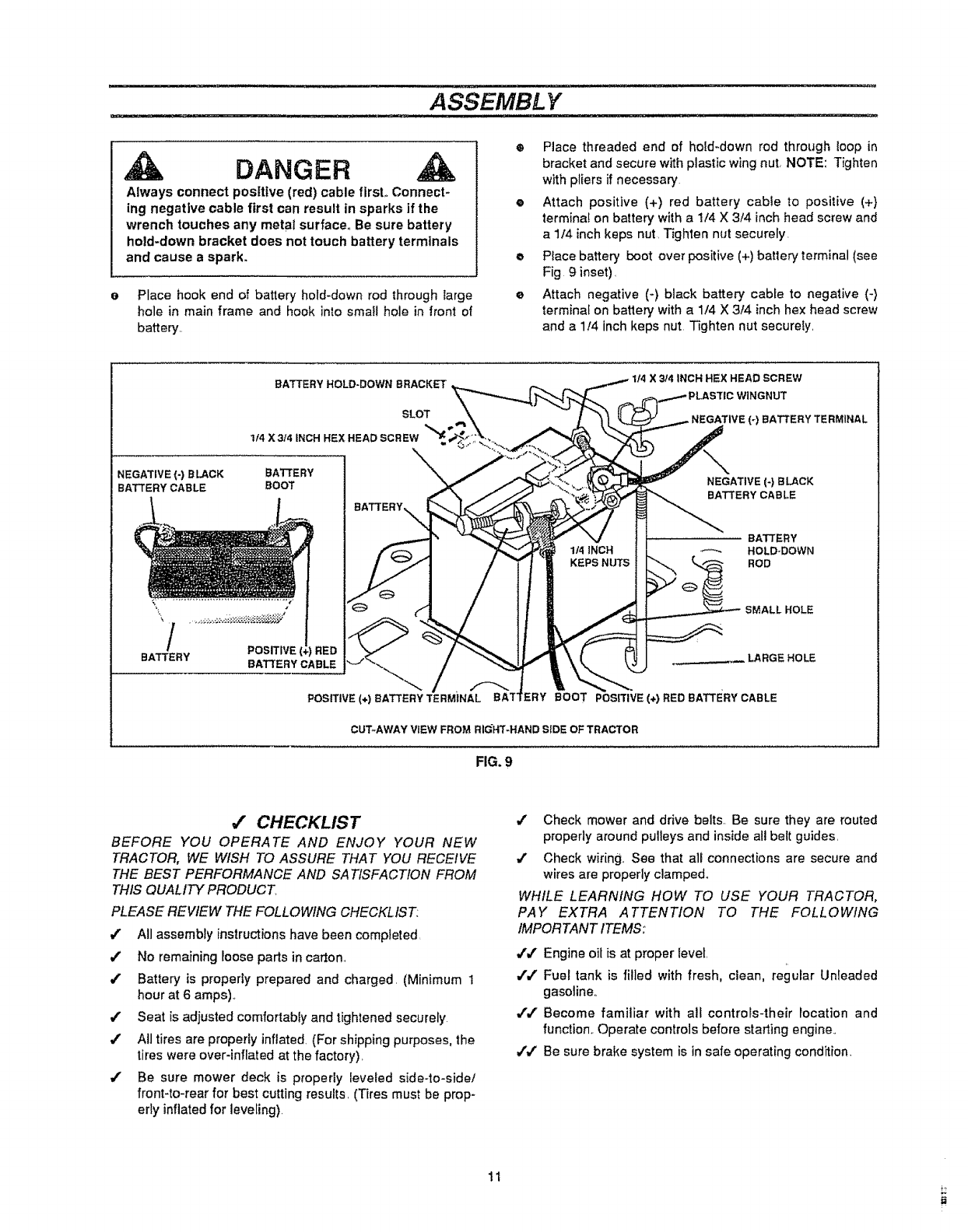
DANGER
Always connect pos[ttve (red) cable first. Connect-
ing negative cable first can result in sparks if the
wrench touches any metal surface. Be sure battery
hold-down bracket does not touch battery terminals
and cause a spark.
Place hook end of battery hold-down rod through large
hole in main frame and hook into smalt hole in front of
batter_'..
Place threaded end of hold-down rod through loop in
bracket and secure with plastic wing nut, NOTE: Tighten
with pliers if necessary
e Attach positive (+) red battery cable to positive (+}
terminal on battery with a 1/4 X 3/4 inch head screw and
a 1/4 inch keps nut, Tighten nut securely.
o Place battery boot over positive (+) battery terminal (see
Fig 9 inset),
eAttach negative (+) black battery cable to negative (-)
terminal on battery with a 1/4 X 314 inch hex head screw
and a 1t4 inch keps nut, Tighten nut securely,
BATTERY HOLD-DOWN BRACKET
SLOT
114 X 3/4 INCH HEX HEAD
NEGATIVE (-) B LACK BATTERY
BATTERY CABLE BOOT
t
/.oo+,+
POSITIVE (+) BATTERY TERMINAL
X 3/4 INCH HEX HEAD SCREW
(-) BATTERY TERMINAL
NEGATIVE (-) BLACK
BATTERY CABLE
BATTERY
HOLD-DOWN
ROD
SMALL HOLE
ERY BOOT POSITIVE (+) RED BATTERY CABLE
CUT+AWAY VIEW FROM RIGHT-HAND SIDE OF TRACTOR
FIG. 9
,# CHECKLIST
BEFORE YOU OPERATE AND ENJOY YOUR NEW
TRACTOR, WE WISH TO ASSURE THAT YOU RECEIVE
THE BEST PERFORMANCE AND SATISFACTION FROM
THIS QUALITY PRODUCT,
PLEASE REVIEW THE FOLLOWING CHECKLIST:
All assembly instructions have been completed,
/No remaining loose parts in carton,
./ Battery is properly prepared and charged, (Minimum I
hour at 6 amps)+
/Seat is adjusted comfortably and tightened securely
/All tires are properly inflated, (For shipping purposes, the
tires were over-inflated at the factory),
/ Be sure mower deck is property leveled side-to-side/
front-to-rear for best cutting results, (T_res must be prop-
erty inflatedfor leveling).
/Check mower and drive belts. Be sure they are routed
properly around pulleys and inside all belt guides,
,,z Check wiring+ See that all connections are secure and
wires are properly clamped.
WHILE LEARNING HOW TO USE YOUR TRACTOR,
PAY EXTRA ATTENTION TO THE FOLLOWING
IMPORTANT ITEMS:
,Y/ Engine oil is at proper level,
,1"/ Fuel tank is filled with fresh, clean, regurar Unleaded
gasoline,,
,[/ Become familiar with all controls-their tocation and
function+ Operate controls before starting engine,,
// Be sure brake system is in safe operating condition.
11
OPERATION
KNOW YOUR TRACTOR
READ THIS OWNER'S MANUAL, AND SAFETY RULES BEFORE OPERATING YOUR
TRACTOR
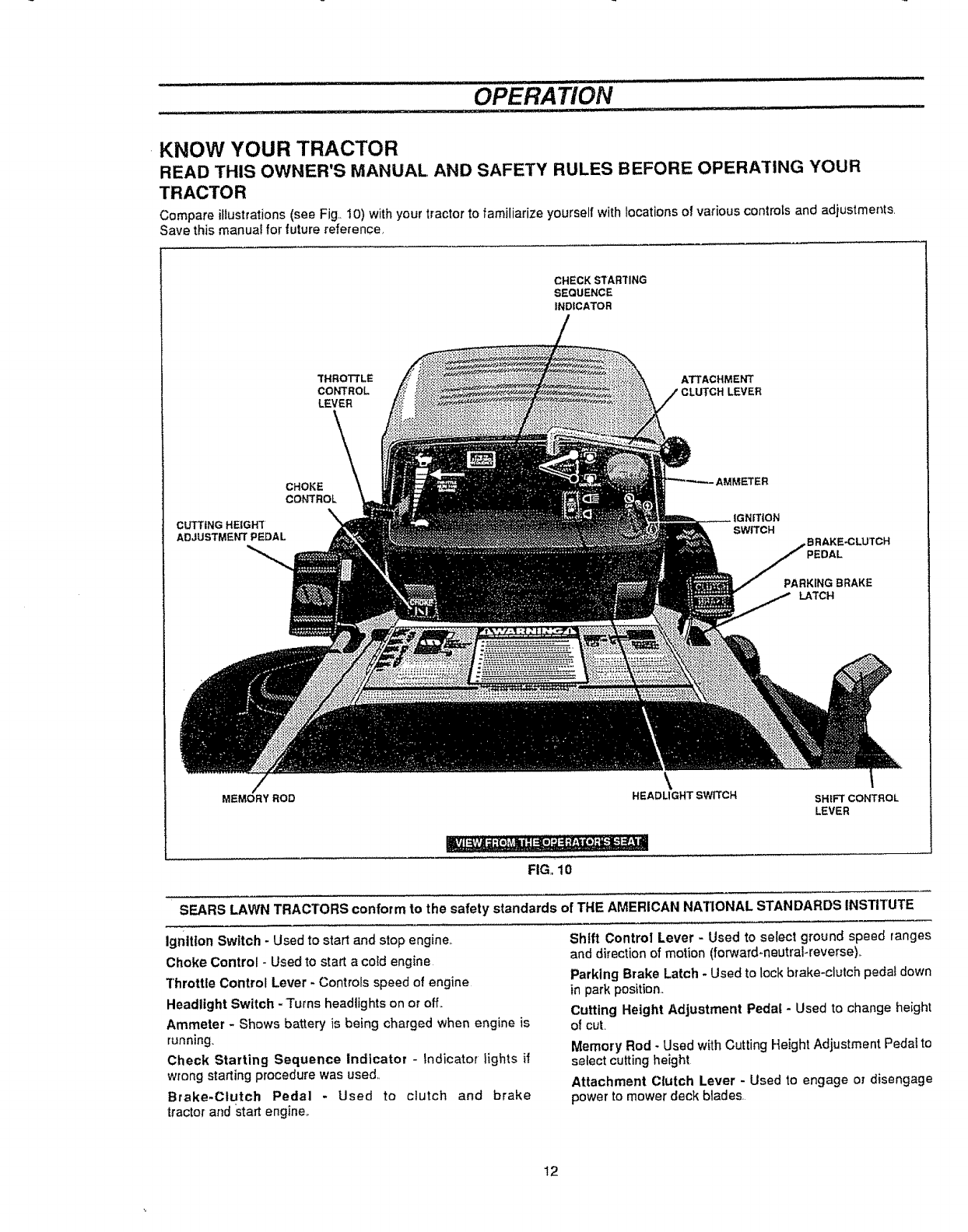
Compare illustrations(see Fig,_I0) withyour tractorto familiarize yourself withlocations of various controis and adjustments
Save this manuat for future reference,
CHECKSTARTING
SEQUENCE
INDICATOR
THROTTLE ATTACHMENT
CONTROL LEVER
LEVER
\
CHOKE
CONTROL
cUTTING HEIGHT
ADJUSTMENT PEDAL
_ETER
BRAKE_LUTCH
LATCH
MEMORYROD \
HEADLIGHT SWITCH
_,_ ,. • ,,._,',,....................
FIG, 10
SH|FTCONTROL
LEVER
SEARS LAWN TRACTORS conform to the safety standards of THE AMERICAN NATIONAL STANDARDS INSTITUTE
ignition Switch -Used to start and stop engine,.
Choke Control - Used to start a cold engine
Throttle Control Lever - Controls speed of engine
Headlight Switch - Turns headlights on or off_
Ammeter - Shows battery is being charged when engine is
running_
Check Starting Sequence Indicator - Indicator lights if
wrong starting procedure was used,,
Brake-Clutch Pedal - Used to clutch and brake
tractor and start engine_
Shift Control Lever -Used to select ground speed ranges
and directionof motion (forward-neutral-reverse)_
Parking Brake Latch -Used to lock brake-clutch pedaI down
in park position..
Cutting Height Adjustment Pedal - Used to change height
of cuL
Memory Rod. Used with Cutting Height Adjustment Pedal to
select cutting height
Attachment Clutch Lever - Used to engage or disengage
power to mower deck blades.
12
OPERATION
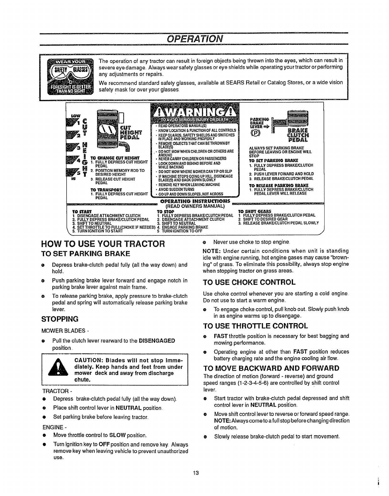
The operation of any tractor can resuftin foreign objects being thrown into the eyes, which can result in
severe eye damage Always wear safety gfasses or eye shields while operating your tractor or performing
any adjustments or repairs.,
We recommend standard safety glasses, available at SEARS Refail or Catalog Stores, or a wide vision
safety mask for over your glasses
LOW
THEmG_
G1., FULLY DEPRESS CDT HEIGHT
PEDAL
_J_ _ 2, POSmON MEMORYRODTO
DESIRED HEtGHT
i_1 3 RELEASECUT HE{GHT
PEDAL
1'O_I_.M_SPORY
1,, FULLY DEPRESS CUT HE]GHT
PEDAL
• READOPERATORSIMNUAL(S)
KNOWLDCATZoN&FUNCTIONOFALLCONTROLS
, KEE_GUARDS SAFETfSHIELDSANDSWffCHES
NPLACE J_J'_OWORK NG PROPERLY
*REMOVE OSJECTSTHATCAN BETHROWN BY
sueDE(s)
,DO N_ UOW WHEN C_LDREN OR OTHERS ARE
"AROUND
• NEVER CARRY CHILDREN OR PASSENGERS
LOOK DOWNAND BERIND BEFORE AND
WHILEBACKING
DONOTMOWWHEREMOWERCANTIPORSLIP
IF MACHINESTOPS GOING UP HiLL OISENGAGE
BLADE(5_AND SACK DOWN SLOWLY
,REUOYEKEYWHENLEAVINGMACHINE
AVOID SUDDEN TURRS
, GO UP AND DOWNSLOPERpNOT ACROSS
PEDAL
ALWAYS SET PARKING BRAKE
BEFORE LEAVING OR ENGINE WILL
STOP
1, FULLY DEPRESS BRAKFJCLUTCH
PEDAL
2. PUSH LEVER FOWARD AND HOLD
3, RELEASE BRAKEtCLb'TCH PEDAL
TO RELEASE PA._RING BD-,,ttJKE
t, FULLY DEPRESS BRAKE.tCLUTCH
PEDAL LEVER W1LL RELEASE
OPERATING IHSTItUCTIOH$
....... (READOWNERSMANUAL) _,_._=_!_:_ :._*-..................... _i_
TO START TO STOP TO SHIFT _r, ARS
1. DISENGAGEAT[ACHMF___,ffCLUTCH 1, FULLY DEPRESS SRAKEgCLUTCH PEDAL t FULLY DEPRESS BRAKE/CLUTCH PEDAL
2. FULLY DEPRESS BRAKEJCLUTCHPEDAL 2, DBENGAGEArTACHMENTCLUTCH 2 SHIFTTODES_REDGEAR
3_ SHF[ TO NEUTRAL 3. SH]F[TO NEUTRAL 3. RELEASE BRAKFJCLUTCH PEDAL SLOWLY
4. SETTHROTTLETO FULL(CHOKE ]F NEEDED) 4., ENGAGE PARKING BRAKE
\,,,5. TURN IGNiTiON TO START 5TURN IGNmON TO OFF
HOW TO USE YOUR TRACTOR
TO SET PARKING BRAKE
eDepress brake-clutch pedal fully (all thG way down) and
hold,,
eNever use choke to stop engine,
NOTE: Under certain conditions when unit is standing
idle with engine running, hot engine gases may cause "brown-
ing" of grass,, To eliminate this possibility, always stop engine
when stopping tractor on grass areas.
ePush parking brake lever forward and engage notch in
parking brake lever against main frame.
oTo release parking brake, apply pressure to brake-clutch
pedal and spring will automaticaUy release parking brake
lever°
STOPPING
MOWER BLADES -
•Puff the clutch lever rearward to the DISENGAGED
position,
CAUTION: Blades will not stop imme-
diately. Keep hands and feet from under
mower deck and away from discharge
chute.
TRACTOR -
• Depress brake-clutch pedal fully (all the way down),
e Place shift control lever in NEUTRAL position.
• Set parking brake before leaving tractor,
ENGINE -
•Move throttle control to SLOW position,
• Turn ignition key to OFF position and remove key, Always
remove key when teaving vehicle to prevent unauthorized
use_
TO USE CHOKE CONTROL
Use choke control whenever you are starting a cold engine
Do not use to start a warm engine,
• To engage choke control, pull knob out, Slowly push knob
in as engine warms up to disengage,,
TO USE THROTTLE CONTROL
•FAST throttle position is necessary for best bagging and
mowing parformance.
• Operating engine at other than FAST position reduces
battery charging rate and the engine cooling air flow,
TO MOVE BACKWARD AND FORWARD
The direction of motion (forward - reverse) and ground
speed ranges (1-2-3-4-5-6) are controlled by shiftcontrol
lever,,
•Start tractor with brake-dutch pedal depressed and shift
control lever in NEUTRAL position.
• Move shift control lever to reverse or forward speed range_
NOTE: Always come to a full stop before changing direction
of motion,,
e Slowly release brake-clutch pedal to start movement.
13
t
.................. OPERATZON
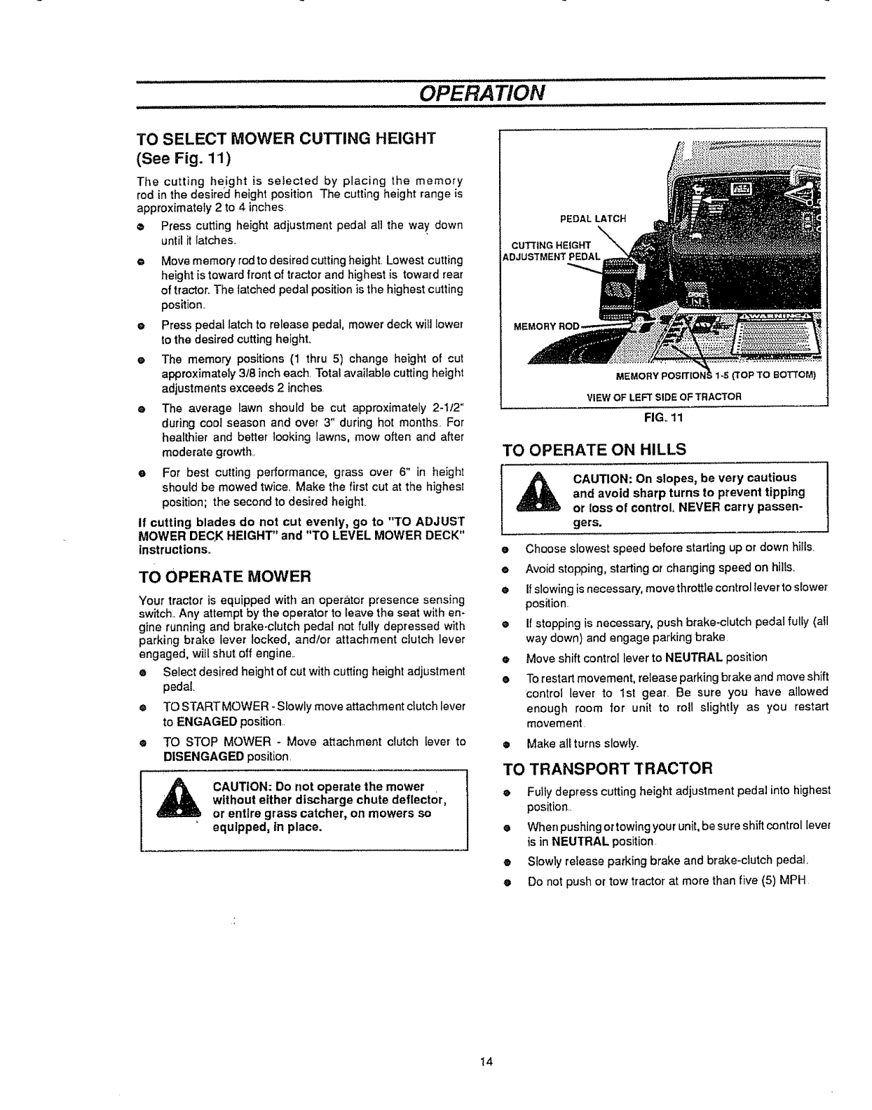
TO SELECT MOWER CUTTING HEIGHT
(See Fig. 11)
The cutting height is selected by placing the memory
rod in the desired height position The cutting height range is
approximately 2 to 4 inches
o Press cutting height adjustment pedal all the way+ down
until it lalches,+
• Move memory rod to desired cutting height. Lowest cutting
height is towardfront of tractor and highest is toward rear
of tractor. The latched pedal position is the highest cutting
position.,
e Press pedal latch to release pedal, mower deck will tower
to the desired cutting heighL
eThe memory positions (1 thru 5) change height of cut
approximately 3t8 inch each. Total available cutting height
adjustments exceeds 2 inches
eThe average lawn should be cut approximately 2-1t2"
during cool season and over 3" during hot months, For
healthier and better looking lawns, mow often and after
moderate growth,.
e For best cutting performance, grass over 6" in height
should be mowed twice, Make the first cut at the highest
position; the second to desired height.
if cutting blades do not cut evenly, go to "TO ADJUST
MOWER DECK HEIGHT" and "TO LEVEL MOWER DECK"
instructions,.
TO OPERATE MOWER
Your tractor is equipped with an operator presence sensing
switch..Any attempt by the operator to leave the seat with en-
gine running and brake+clutch pedal not fully depressed with
parking brake lever locked, and/or attachment clutch lever
engaged, will shut off engine..
eSelect desired height of cut withcutting height adjustment
pedal
® TO START MOWER +Slowly move attachment clutch lever
to ENGAGED position..
•TO STOP MOWER +Move attachment clutch iever to
DISENGAGED position.
CAUTION: Do not operate the mower
without either discharge chute deflector,
or entire grass catcher, on mowers so
equipped, tn place.
PEDAL LATCH
CUTTING HEIGHT
ADJUSTMENT PEDAL
MEMORY F _1-5{'tOP TO BOTTOM)
VIEW OF LEFT SIDE OF TRACTOR
FIG. 11
TO OPERATE ON HILLS
CAUTION: On slopes, be very cautious
and avoid sharp turns to prevent tipping
or loss of control, NEVER carry passen-
gers.
eChoose slowest speed before starting up or down hills.
eAvoid stopping, starting or changing speed on hills.
®If slowing is necessary, move throttlecontrollever to slower
position.
® It stopping is necessary, push brake-clutch pedal fully (oil
way down) and engage parking brake,
e Move shift control lever to NEUTRAL position
• Torestart movement, release parkingbrake and move shift
control lever to 1st gear, Be sure you have allowed
enough room for unit to roll slightly as you restart
movement.
• Make all turns slowly+
TO TRANSPORT TRACTOR
• Fully depress cutting height adjustment pedal into highest
position..
• Whenpushingortowing your unit, be sure shift control lever
is in NEUTRAL position.
e Slowly release parking brake and brake+clutch pedal.
• Do not push or tow tractor at more than five (5) MPH
14
OPERA TION
BEFORE STARTING THE ENGINE
CHECK ENGINE OIL LEVEL
Read OPERATION and CUSTOMER RESPONSIBILITIES
sections of this manual before trying to start the engine
•Check to make sure engine crankcase is full of oil Never
run engine unless crankcase is lull of oil and dipstick is
tightened securely into oi! tube
eTo change engine oil, see ENGINE LUBRICATION in
CUSTOMER RESPONSIBILITIES section of this
manual.
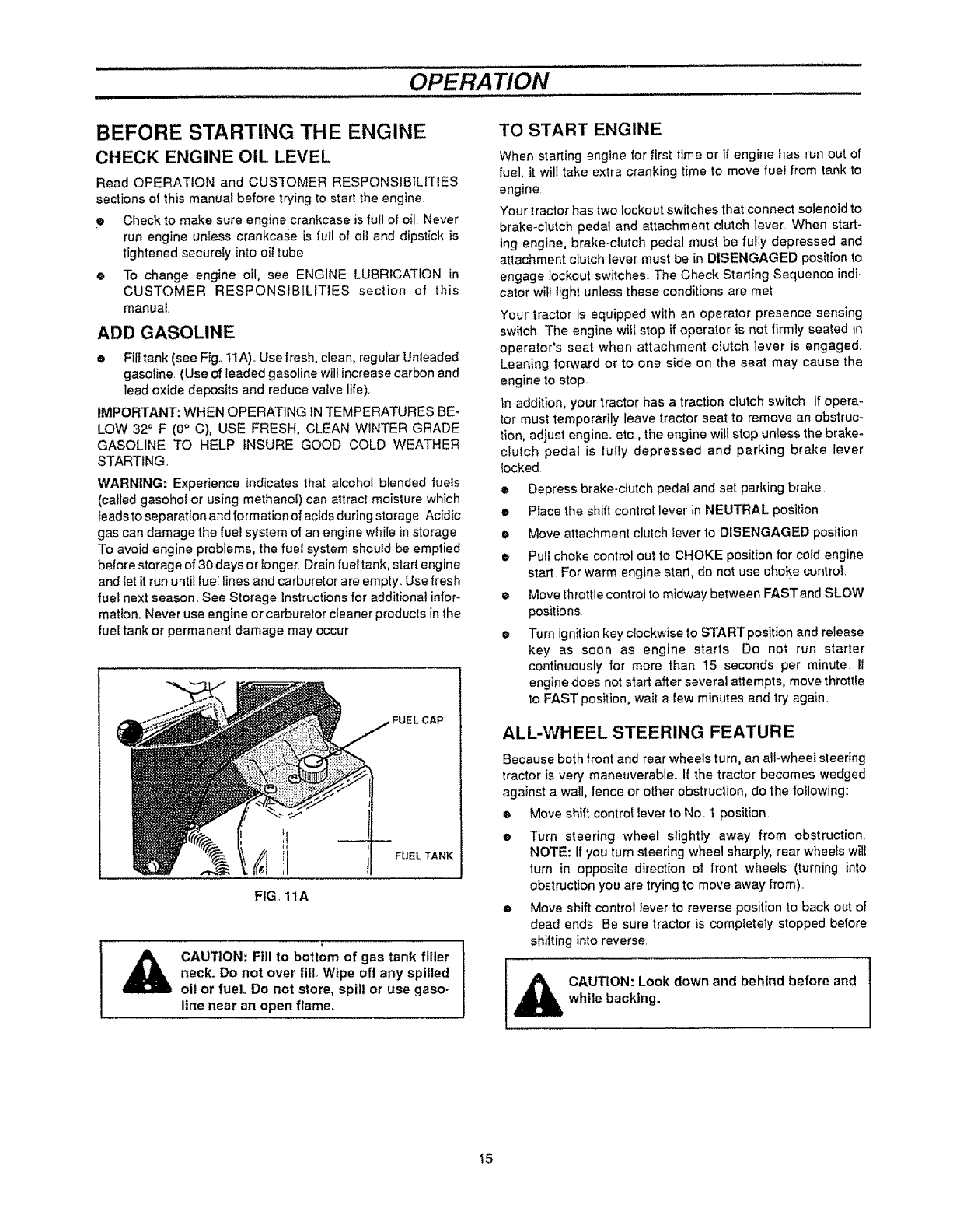
ADD GASOLINE
eFill tank (see Fig.. 11A)+Use fresh, clean, regular Unleaded
gasoline. (Use of leaded gasoline will increase carbon and
lead oxide deposits and reduce valve life).
IMPORTANT: WHEN OPERATING IN TEMPERATURES BE +
LOW 32° F (0° C), USE FRESH, CLEAN WINTER GRADE
GASOLINE TO HELP INSURE GOOD COLD WEATHER
STARTING..
WARNING: Experience indicates that alcohol blended fuels
(called gasohol or using methanol) can attract moisture which
leads to separation and formation of acids during storage Acidic
gas can damage the fuel system of an engine while in storage
To avoid engine problems, the fuel system should be emptied
belore storage of 30 days or Ionger. Drain fuel tank, start engine
and let it run until fuel lines and carburetor are empty. Use fresh
fuel next season. See Storage Instructions for additional inior+
mation. Never use engine or carburetor cleaner products in the
fuel tank or permanent damage may occur
,FUEL CAP
FIG+,11A
FUEL TANK
_lb CAUT|ON: Fill to bottom of gas tank filler
neck. Do not over fill Wipe off any spilled
oi! or fuel,. Do not store, spill or use gaso-
line near an open flame.
TO START ENGINE
When starting engine for first time or if engine has run out of
fuel, it will take extra cranking time to move fuel from tank to
engine
Your tractor has two lockout switches that connect solenoid to
brake+clutch pedal and attachment clutch lever, When start-
ing engine, brake-clutch pedal must be fully depressed and
attachment clutch lever must be in DISENGAGED position to
engage lockout switches The Check Starting Sequence indi-
cator wit! light unless these conditions are met
Your tractor is equipped with an operator presence sensing
switch. The engine will stop if operator is not firmly seated in
operator's seat when attachment clutch lever is engaged.
Leaning forward or to one side on the seat may cause the
engine to stop.
in addition, your tractor has a traction clutch switch. If opera-
tor must temporarily leave tractor seat to remove an obstruc-
tion, adjust engine, etc, the engine will stop unless the brake-
clutch pedat is fully depressed and parking brake lever
locked.
•Depress brake-clutch pedal and set parking brake
•Place the shift control lever in NEUTRAL position
• Move attachment clutch lever to DISENGAGED position
• Pull choke control out to CHOKE position for cold engine
start, For warm engine start, do not use choke control,
•Move throttle control to midway between FAST and SLOW
positions
eTurn ignition key clockwise to START position and release
key as soon as engine starts, Do not run starter
continuously for more than t5 seconds per minute if
engine does not start after several attempts, move throttle
to FAST position, wait a few minutes and try again..
ALL-WHEEL STEERING FEATURE
Because both front and rear wheels turn, an all+wheel steering
tractor is very maneuverable. If the tractor becomes wedged
against a wall, fence or other obstruction, do the following:
o Move shift control lever to No. I position
o Turn steering wheel slightly away from obstruction.
NOTE: If you turn steering wheel sharply, rear wheels will
turn in opposite direction of front wheels (turning into
obstruction you are trying to move away from).
eMove shift control lever to reverse positionto back out of
dead ends Be sure tractor is completely stopped before
shifting into reverse.
_AUTION: Look down and behind before and
while backing.
t5
OPERATION
MOWING TIPS
eDo not use tire chains when mower housing is attached to
unit
eRun the engine at FAST speed position.
• Control forward ground speed with shift control lever in
accordance with type and quantity of grass being
mowed. The more grass to be cut, a slower forward
ground speed should be used. When cutting light grass,
forward ground speed can be increased By observing
cutting action of your mower, you can determine the
forward g round speed_
eYour mower may tend to leave unmowed strips when long
and tender gr ass is being mowed Tender grass has a high
internal moisture content and is easily depressed by lawn
tractor wheels, and may not always spring back in time to
be cut. To overcome this condition, we advise mowing lawn
in a counterclockwise direction, overlapping previous cut,
which allows lifting action of rotating blades to lift grass into
cutting path.
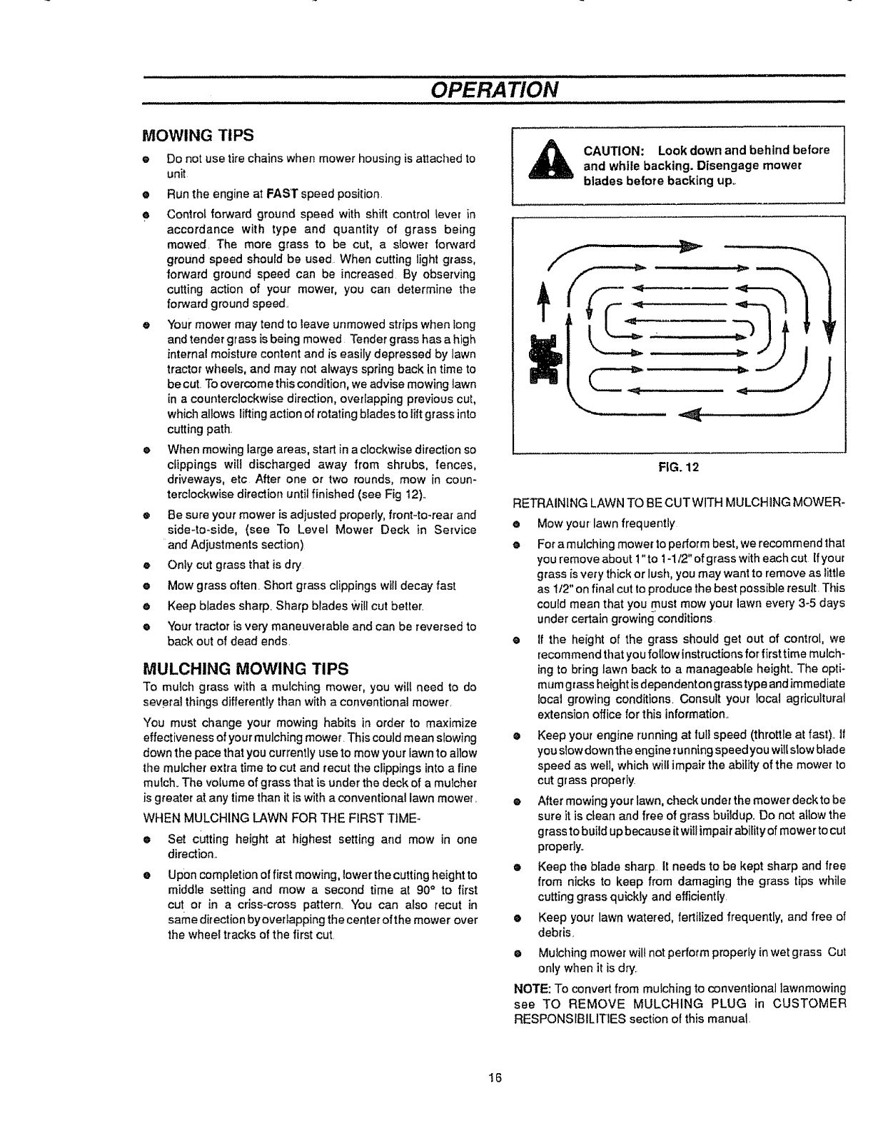
e When mowing large areas, start in a clockwise direction so
clippings will discharged away from shrubs, fences,
driveways, etc After one or two rounds, mow in coun-
terclockwise direction until finished (see Fig 12).,
eBe sure your mower is adjusted properly, front-to-rear and
side-to-side, (see To Level Mower Deck in Service
•and Adjustments section)
eOnly cut grass that is dry
eMow grass often Short grass clippings wilt decay fast
e Keep blades sharp. Sharp blades vviflcut better.
eYour tractor is very maneuverable and can be reversed to
back out of dead ends.
MULCHING MOWING TIPS
To mulch grass with a mulching mower, you wilt need to do
several things differently than with a conventional mower.
You must change your mowing habits in order to maximize
effectiveness of your mulching mower. This could mean siowing
down the pace that you currently use to mow your fawn to allow
the mulcher extra time to cut and recut the clippings into a fine
mulch_The volume of grass that is under the deck of a mulcher
is greater at any time than itis with a conventional lawn mower_
WHEN MULCHING LAWN FOR THE FIRST T1ME-
•Set cutting height at highest setting and mow in one
direction._
eUpon completion of first mowing, lower the cutting height to
middle setting and mow a second time at 90° to first
cut or in a cfiss-cross pattern. You can also recur in
same direction by overlapping the center of the mower over
the wheel tracks of the first cut.
,_ CAUTION: Look down and behind beforeand white backing. Disengage mower
blades before backing upo
FIG. 12
RETRAINING LAWN TO BE CUTWITH MULCHING MOWER-
•Mow your lawn frequently
eFor a mulching mower to performbest, we recommend that
you remove about ! "to 1-1/2" of grass with each cut ifyour
grass is very thick or lush, you may want to remove as little
as tt2" on final cut to produce the best possible result. This
could mean that you must mow your lawn every 3-5 days
under certain growing conditions
•If the height of the grass should get out of control, we
recommendthat you follow instructions for first time mulch-
ingto bring lawn back to a manageable height. The opti-
mumgrass height isdependent on grass type and immediate
local growing conditions, Consult your local agricultural
extension office for this information.
• Keep your engine running at full speed (throttleat fast) 11
youslow downthe engine running speedyou willslow bfade
speed as well, which will impair the ability of the mower to
cut grass properly.
•After mewing your lawn, check under the mower deck to be
sure it is clean and free of grass buildup. Do not allow the
grass to build up because itwill impair ability of mower to cut
properly,.
• Keep the blade sharp It needs to be kept sharp and free
from nicks to keep from damaging the grass tips while
cutting grass quickly and efficiently
eKeep your lawn watered, fertilized frequently, and free of
debris,
•Mulching mower willnot perform properly in wet grass Cut
only when it is dry..
NOTE: To convert from mulching to conventional Iawnmowing
see TO REMOVE MULCHING PLUG in CUSTOMER
RESPONSIBILITIES section ot this manual.
16
CUSTOMER RESPONSIBILITIES
GENERAL RECOMMENDATIONS
The warranty on thistractor does not cover items that have been
subjected to operator abuse or negligence To receive full value
from warranty, operator must maintain lawn tractor as instructed
in this manual
.Some adjustments will need to be made periodically to properly
maintain your uniL
All adjustments in the SERVICE AND ADJUSTMENTS section
of this manual should be checked at least once each season.
Once a year you should replace spark plug. clean or
replace air filter, and check blades and belts for wear. A
new spark plug and clean air filter assure proper air-fuel
mixture and help your engine run better and last longer
BEFORE EACH USE
•Check engine oii level..
oCheck brake operation.
•Check tire pressure
eCheck for loose tasteners
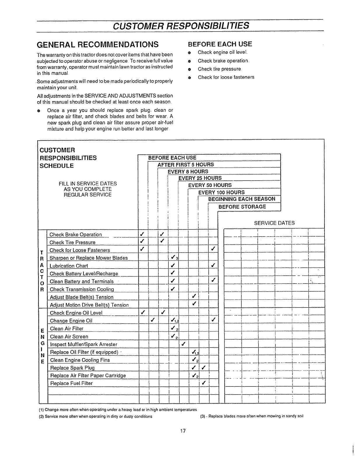
CUSTOMER
RESPONSIBILITIES
SCHEDULE
FILL IN SERVICE DATES
AS YOU COMPLETE
REGULAR SERVICE
BEFORE EACH USE
AFTER FIRST 5HOURS
+EVERY 8 HOURS I
i
EVERY 25 HOURS
EVERY 50 HOURS
tEVERY 100 HOURS
BEGINNING EACH SEASON
i ,
' t BEFORE STORAGE
J++i
+.i i SERVICE DATES
Check Brake Operat!on J = _ ! ! I
.......... '..... _ .... .4. = !
Check Tire Pressure " i _ :1
T Check for Loose Fasteners v" 4' I _
R Sharpen or Replace Mower BIades + 4"3 . , ,_ ____[. '/ ..__
A Lub,oa_+nCha..... I ' + J _ i___4 i !. !
° -1 ., _T_[:
T0 Clean Battery and Terminals I _ ii i::_____ _ZZ__----, j_ ....... J" _-_
RCheckTransmissi0n Coo!ing t 4" ! J + 1 ! I I
Adjust Blade Belt(s) Tension I _-2-T_ _- ....
Adjust Motion Drive Belt(s) Tension + _...! i I _ ! I .._ ! t i
Check Engine Oil Level 4" _ ! ' + "-'-_- ............ i .... J I
Change Engine Of.!
Clean Air Fi+ter
Clean Air Screen
!,
......... I--- #"
'/'2 , ,
iinspe_ MufflertSpark Arresie; ........ J {............I i
Re#iaceQii Filter (if equipped)- i ! ! ,4,._ I
i i + I
..................t I
+ 4' [ t
C ean Eng ne Coo ing Fins i J 2 ;I j I i '
Replace Spark PIug ..... i--- j _ -{ J } '
:l
.......................................... | i .......... ...... ,_ " "
Replace Air Filter.........Paper Cartridge 1 , ! ! lJ'21 ;i' J'2 ' " ....... -_'---q J '
, ' +......i- ......!-+----j---d-- _
Replace Fuel Filter ! _ I '/ i
......................... + i ! • ...............i i I .....
l . t...... I , .
E
N
N
E
(1) Change more oiler} when operating ur_der a heavy load or in high ambient temperatures
(2) Service more often when operating in dirty or dusty conditions (3) - Replace blades more often when mowing in sandy soil
t7
!
CUSTOMER RESPONSIBILITIES
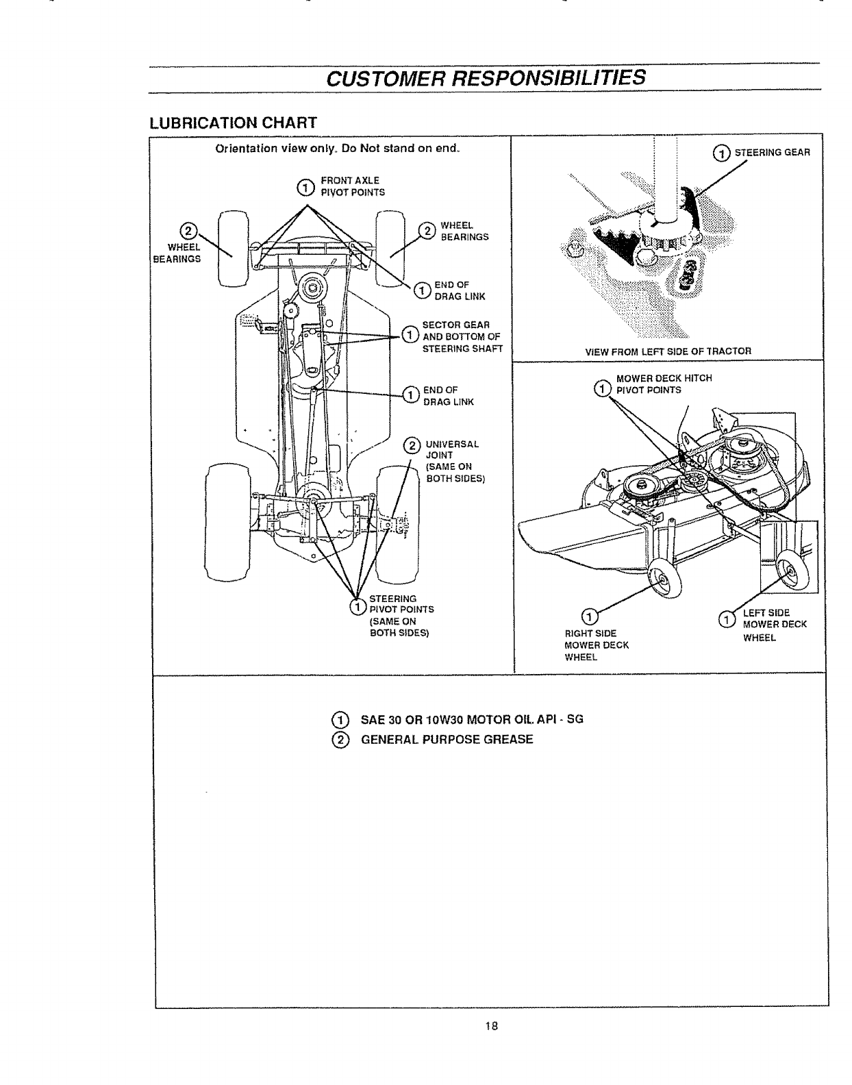
LUBRICATION CHART
Orientation view only,, Do Not stand on end_ OSTEERINGGEAR
QFRONTAXLE
PIVOT POINTS
WHEEL
BEARINGS
(_END OF
DRAG LiNK
SECTOR GEAR
IAND BOTTOM OF
STEER1NG SHAFT
ENDOF
DRAG LINK
UNIVERSAL
JOINT
(SAME ON
BOTH SIDES)
STEERING
IPIVOT POINTS
(SAME ON
BOTH SIDES)
VIEW FROM LEFT SIDE OF TRACTOR
MOWER DECK HITCH
PIVOT POINTS
RIGHT SIDE
MOWER DECK
WHEEL
EoFTSIDE
WER DECK
WHEEL
QSAE 30 OR 10W30 MOTOR OIL API -SG
@GENERAL PURPOSE GREASE
t8
CUSTOMER RESPONSIBILITIES
TRACTOR
Always observe safety rules when performing any
maintenance..
BRAKE OPERATION
Your tractor is equipped withan adjustable disc brake To check
brake operation do the following:
• Stoptractor on a level surface and place shift control lever
in NEUTRAL position.
eDepress brake_clutch pedal enough to latch parking brake
in 2nd notch.
e Try to push tractor, lf you are unable to push tractor, brake
is too tight and should be loosened (see TO ADJUST
TRACTOR BRAKE in SERVICE AND ADJUSTMENTS
section of this manual.
e Depress brake-clutch pedal enough to latch parking brake
in 4th notch_
eTry to push tractor If you are able to push tractor, brake is
too loose and should be tightened (see TO ADJUST
TRACTOR BRAKE in SERVICE AND ADJUSTMENTS
section of this manual.,
During tractor operation, check for stopping distance..If tractor
requires more than six (6) feet stopping distance at high speed
in highest gear, the brake must be adjusted (see to ADJUST
TRACTOR BRAKE in SERVICE AND ADJUSTMENTS section
of this manual),
e Maintain proper air pressure in all tires,, (See"PRODUCT
SPECIFICATIONS" on page 3 of this manual),
e Keep tires free of gasoline, oil, or insect controlchemicals
which can harm rubber.
oAvoid stumps, stones, deep ruts, sharp objects and other
hazards that may cause tire damage
CAUTION: BEFORE PERFORMING ANY
SERVICE OR ADJUSTMENTS
• Fully depress brakeoctutch pedal and set
parking brake.,
e Place shift control lever in NEUTRAL
position,
• Place attachment clutch lever in DISEN-
GAGED position,,
e Turn ignition key OFF and remove key°
• Make sure the blades and all movtng
parts have completely stopped,
• DO NOT handle blades with bare hands.
Wear gloves or wrap blade with news-
paper or other material while removing
or Installing blade.
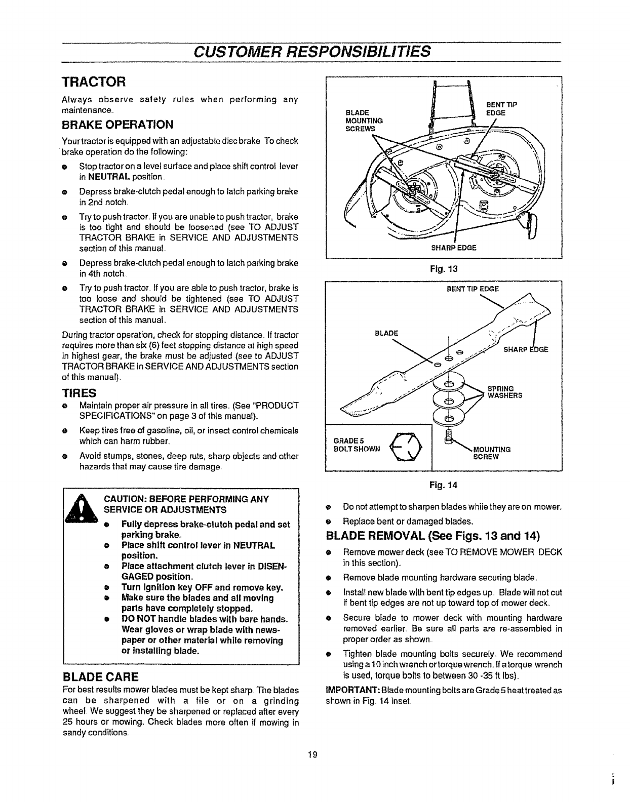
BLADE CARE
For best results mower blades must be kept sharp The blades
can be sharpened with a file or on a grinding
wheel. We suggest they be sharpened or replaced after every
25 hours or mowing, Check blades more often if mowing in
sandy conditions.,
BLADE
MOUNTING
SCREWS
SHARPEDGE
Fig, 13
BENTTIPEDGE
BLADE
SPRING
WASHERS
GRADE 5Q
BOLT SHOWN MOUNTING
SCREW
Fig° 14
•Do not attempt to sharpen blades while they are on mower,
e Replace bent or damagedbladeso
BLADE REMOVAL (See Figs. 13 and 14)
• Remove mowerdeck (seeTO REMOVE MOWER DECK
in this section),,
•Remove blade mounting hardware securing blade
•Install new blade with bent tip edges up.. Blade wiUnot cut
if bent tip edges are not up toward top of mower deck,
eSecure biade to mower deck with mounting hardware
removed earlier_ Be sure all parts are re-assembled in
proper order as shown.
eTighten blade mounting bolts securely, "Werecommend
using a 10 inch wrench ortorque wrench, If atorque wrench
is used, torque bolts to between 30 -35 ft lbs).
IMPORTANT: Blade mounting bolts are Grade 5 heat treated as
shown in Fig° 14 inset.
!9
CUSTOMER RESPONSIBILITIES
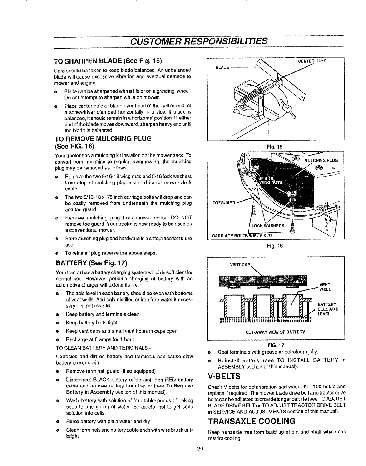
TO SHARPEN BLADE (See Fig= 15)
Care should be taken to keep blade balanced An unbalanced
blade wilt cause excessive vibration and eventual damage to
mower and engine
•Blade can be sharpened witha file or on a grinding wheel
Do not attempt to sharpen while on mower.
ePlace center hole of blade over head of the nail or end of
a screwdriver clamped horizontally in a vice. If blade is
balanced, it should remain in a horizontal position. If either
end of the blade moves downward_ sharpen heavy end until
the blade is batanced
TO REMOVE MULCHING PLUG
(See FIG. 16)
Your tractor has a mulching kit installed on the mower deck. To
convert from mulching to regular lawnmowing, the mulching
plug may be removed as follows:
e Remove the two 5/16-18 wing nuts and 5/16 lock washers
from atop of mulching plug installed inside mower deck
chute,
•The two 5/16-18 x ,75 inch carriage bolts wil! drop and can
be easily removed from underneath the mulching plug
and toe guard.
o Remove mulching plug from mower chute DO NOT
remove toe guard. Your tractor is now ready to be used as
a conventional mower.
® Store mulching plug and hardware ina safe placelor future
use.
•To reinstall plug reverse the above steps
BATTERY (See Fig. 17)
Your tractorhas a battery charging system which issufficient for
normal use However, periodic charging of battery with an
automotive charger will extend its life.
• The acid level in each battery should be even with bottoms
of vent wells Add only distilled or ironfree water if neces-
saP/ Do not over fitl
• Keep battery and terminals clean,.
•Keep battery bolts tight,
_, Keep vent caps and small vent holes in caps open
eRecharge at 6 amps for 1 hour.
TO CLEAN BATTERY AND TERMINALS -
Corrosion and dirt on battery and terminals can cause slow
battery power drain.
•Remove terminal guard (if so equipped),
•Disconnect BLACK battery cable first then RED battery
cable and remove battery from tractor (see To Remove
Battery in Assembly section of this manual),
e Wash battery with solution of four tablespoons of baking
soda to one gallon of water Be careful not to get soda
solution into cells.
• Rinsebattery' withplain water and dry.
• Clean terminals and batterycable endswith wirebrush until
bright
2O
BLADE
CENTER HOLE
Fig. 15
MULCHING PLUG
TOEGUARD
CARRIAGE X.75
Fig. 16
VENT CAP \
VENT
BATTERY
CELL ACID
LEVEL
FIG. 17
•Coat terminals with grease or petroleum jelly.
•Reinstall battery (see TO INSTALL BATTERY in
ASSEMBLY section of this manual),.
V-BELTS
Check V-belts for deterioration and wear after 100 hours and
replace if required The mower blade drive belt and tractor drive
belts can be adjusted to providelonger belt life (see TO ADJUST
BLADE DRIVE BELT orTO ADJUST TRACTOR DRIVE BELT
in SERVICE AND ADJUSTMENTS section of this manual)
TRANSAXLE COOLING
Keep transaxle free from build-up of dirt and chaff which can
restrictcooling
CUSTOMER RESPONSIBILITIES
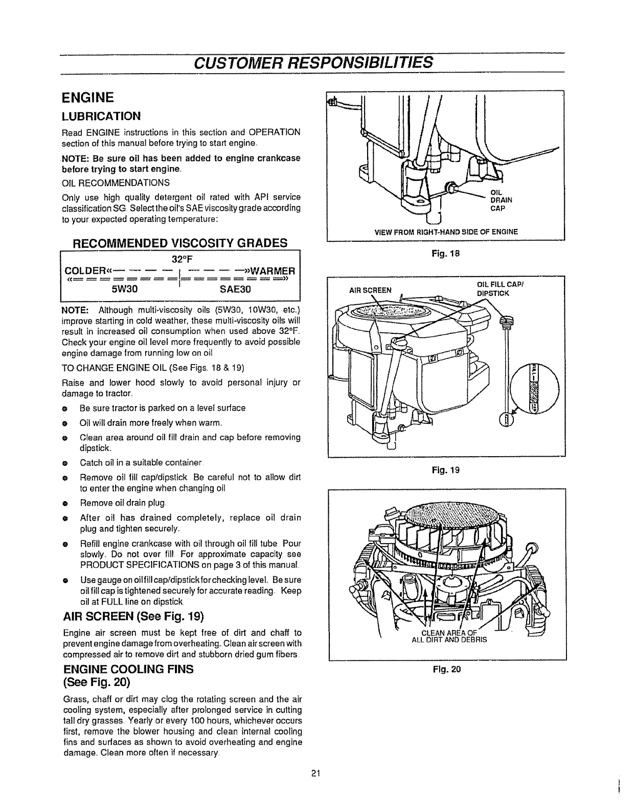
ENGINE
LUBRICATION
Read ENGINE instructions in this section and OPERATION
section of this manual before trying to start engine
NOTE: Be sure oil has been added to engine crankcase
before trying to start engine.
OIL RECOMMENDATIONS
Onty use high quality detergent oil rated with APf service
classification SG Select the oil's SAE viscosity g fade according
to your expected operating temperature:
RECOMMENDED VISCOSITY GRADES
32°F
COLDER_€ I --_WARMER
5W30 SAE30
NOTE: Although multi-viscosity oils (5W30, 10W30, etc..)
improve starting in cold weather, these multi-viscosity oils will
result in increased oil consumption when used above 32°F.
Check your engine oi] level more frequently to avoid possible
engine damage from running low on oil
TO CHANGE ENGINE OIL (See Figs. 18 & 19)
Raise and lower hood slowly to avoid personal injury or
damage to tractor.
eBe sure tractor is parked on a level surface
eOitwill drain more freely when warm.
eClean area around oil fill drain and cap before removing
dipstick.
eCatch oil in a suitable container
eRemove oil fitt cap/dipstick Be careful not to allow dirt
to enter the engine when changing oil
• Remove oii drain plug.
•After oil has drained completely, replace oil drain
plug and tighten securely.
•Refill engine crankcase with oil through oil fill tube Pour
slowly° Do not over fill For approximate capacity see
PRODUCT SPECIFICATIONS on page 3 of this manual.
•Use gauge on oi!fillcap/dipstickfor checking level.. Be sure
oil fill cap istightened securely for accurate reading. Keep
oil at FULL lineon dipstick
AIR SCREEN (See Fig. '19)
Engine air screen must be kept free of dirt and chaff to
preventengine damage from overheating. Clean air screen with
compressed air to remove dirt and stubborn dried gum fibers
ENGINE COOLING FINS
(See Fig. 20)
Grass, chaff or dirt may clog the rotating screen and the air
cooling system, especially after prolonged service in cutting
tall dry grasses Yearly or every 100 hours, whichever occurs
first, remove the blower housing and clean internal cooling
lins and surfaces as shown to avoid overheating and engine
damage. Clean more often if necessary
2I
VIEW FROM RIGHT-HAND SIDE OF ENGINE
Fig, 18
IOIL FILL CAP/
AIR SCREEN DIPSTICK
Fig. 19
CLEAN AREA OF
ALL DIRT AND DEBRIS
Flg. 20
i
CUSTOMER RESPONSIBILITIES
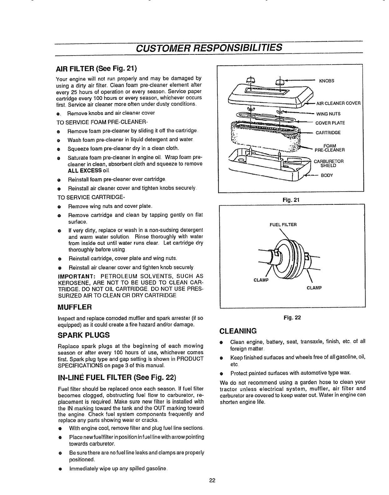
AIR FILTER (See Fig. 21)
"Your engine will not run properly and may be damaged by
using a dirty air filter. Clean foam pre-cteaner element after
every 25 hours of operation or every season. Service paper
cartridge every 100 hours orevery season, whichever occurs
first, Service air cleaner mote often under dusty conditions..
e.. Remove knobs and air cleaner cover
TO SERVICE FOAM PRE-CLEANER-
•Remove foam pre-cleaner by slidingitoff the cartridge.
e Wash foam pre-cleaner in liquiddetergent and water
•Squeeze foam pre_cleaner dry in a clean cloth..
• Saturate foam pre-cleaner in engine oil. Wrapfoam pre-
cleaner in clean, absorbent cloth and squeeze to remove
ALL EXCESS oil
eReinstall foam pre_cieanerover cartridge.
e Reinstall air cleaner cover and tighten knobs securely
TO SERVICE CARTRIDGE-
e Remove wing nuts and cover plate..
e Remove cartridge and clean by tapping gently on flat
surface..
o If very dirty, replace or wash in a non-sudsing detergent
and warm water solution Rinse thoroughly with water
from inside out until water runs clear. Let cartridge dry
thoroughly before using.
• Reinstall cartridge, cover plate and wing nuts.
e Reinstall air cleaner cover and tighten knob securely
IMPORTANT: PETROLEUM SOLVENTS, SUCH AS
KEROSENE, ARE NOT TO BE USED TO CLEAN CAR-
TRIDGE. DO NOT OIL CARTRIDGE. DO NOT USE PRES-
SURIZED AIR TO CLEAN OR DRY CARTRIDGE
MUFFLER
Inspect and replace corroded muffler and spark arrester (if so
equipped) as itcould create a fire hazard and/or damage.
SPARK PLUGS
Replace spark plugs at the beginning of each mowing
season or after every 100 hours of use, whichever comes
first. Spark p!ug type and gap setting is shown in PRODUCT
SPECIFICATIONS on page 3 of this manual.
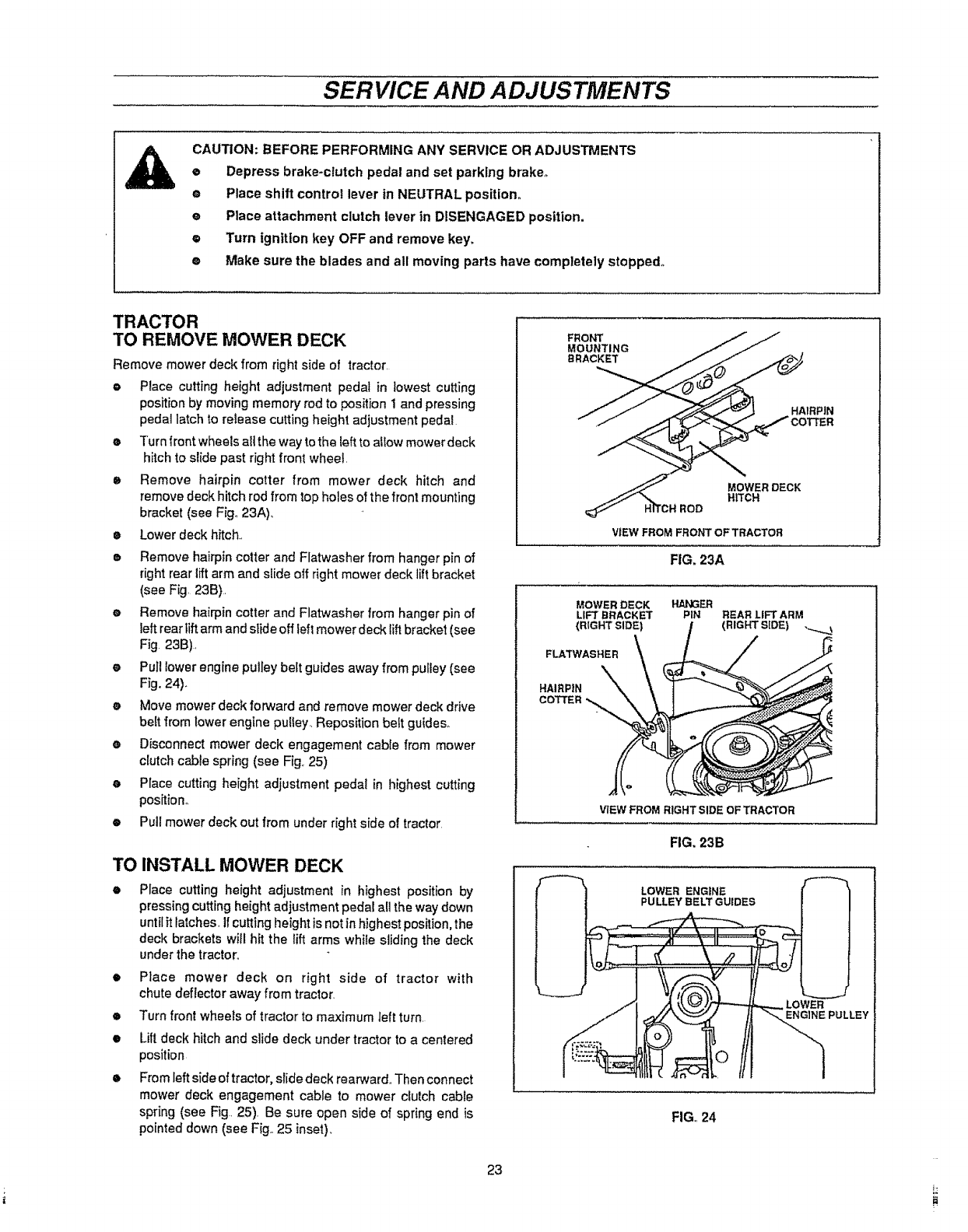
IN-LINE FUEL FILTER (See Fig. 22)
Fuel filter should be replaced once each season. If fuel filter
becomes clogged, obstructing fuel flow to carburetor, re-
placement is required. Make sure new filter is installed with
the IN marking toward the tank and the OUT marking toward
the engine Check fuel system components frequently and
replace any parts showing wear or cracks
• With engine coo!, remove filter and plugfuel line sections.
@
@
@
Place new fuel filter inpositioninfuel line witharrow pointing
towards carburetor.
Be sure there are no fuel line leaks and clamps are properly
positioned..
immediately wipe up any spilled gasoline.
22
KNOBS
_CLEANERCOVER
WING NUTS
COVER PL/_TE
CARTRIDGE
Fig. 21
FUEL FILTER
CLAMP
CLAMP
Fig° 22
CLEANING
@Clean engine, battery, seat, transaxle, finish, etc. of all
foreign matter.
@ Keep finished surfaces and wheels free of all gasoline, oil,
etc
@ Protect painted surfaces with automotive lype wax,
We do not recommend using a garden hose to clean your
tractor unless electrical system, muffler, air filter and
carburetor are covered to keep water ouL Water in engine can
shorten engine life..
SERVICE AND ADJUSTMENTS
CAUTION: BEFORE PERFORMING ANY SERVICE OR ADJUSTMENTS
e Depress brake-clutch pedal and set parking brake°
® Place shift control lever in NEUTRAL position_
e Place attachment clutch lever in DISENGAGED position,
e Turn ignition key OFF and remove key,
® Make sure the blades and all moving parts have completely stopped°
TRACTOR
TO REMOVE MOWER DECK
Remove mower deck from right side of tractor,
e Place cutting height adjustment pedal in lowest cutting
position by moving memory rod to position 1 and pressing
pedal latch to release cutting height adjustment pedal
® Turn |font wheels all the way to the left to allow mower deck
hitch to slide past right front wheel,
• Remove hairpin cotter from mower deck hitch and
removedeck hitch rod from top holes of the front mounting
bracket (see Fig° 23A).,
•Lower deck hitch.,
•Remove hairpin cotter and Flatwasher from hanger pin of
rightrear lift arm and slide off right mower deck lift bracket
(see Fig, 23B).
eRemove hairpincotter and Flatwasher from hanger pin of
left rearlift arm and slide off left mower deck liftbracket (see
Fig 23B),
e Pull lower enginepulley belt guides away from pulley(see
Fig. 24)_
e Move mower deck forward and remove mower deck drive
belt from lower engine pulley, Reposition belt guides_
eDisconnect mower deck engagement cable from mower
clutch cable spring (see Fig 25)
e Place cutting height adjustment pedal in highest cutting
position°
•Pull mower deck out from under rightside of tractor
TO INSTALL MOWER DECK
@Place cutting height adjustment in highest position by
pressing cutting height adjustment pedal all the way down
until it latches, ifcutting height is not in highest position, the
deck brackets will hit the lift arms while sliding the deck
under the tractor.
•Place mower deck on right side of tractor with
chute deflector away from tractor.
•Turn front wheels of tractor to maximum left turn,
eLift deck hitch and slide deck under tractorto a centered
position
@From left side of tractor, slide deck rearward,,Then connect
mower deck engagement cable to mower clutch cable
spring (see Fig. 25). Be sure open side of spring end is
pointeddown (see Fig., 25 inset).
FRONT
MOUNTING
BRACKET
HAIRPIN
MOWERDECK
HITCH
VIEW FROM FROt_I "OF TRACTOR
FIG. 23A
MOWER DECK
LIFT BRACKET
(RIGHT SIDE)
FLATWASHER \\_, I
VIEW FROM RIGHT SIDE OF TRACTOR
FIG. 23B
LOWER ENGINE
PULLEY BELT GUIDES
LOWER
ENGINE PULLEY
FIG,,24
23
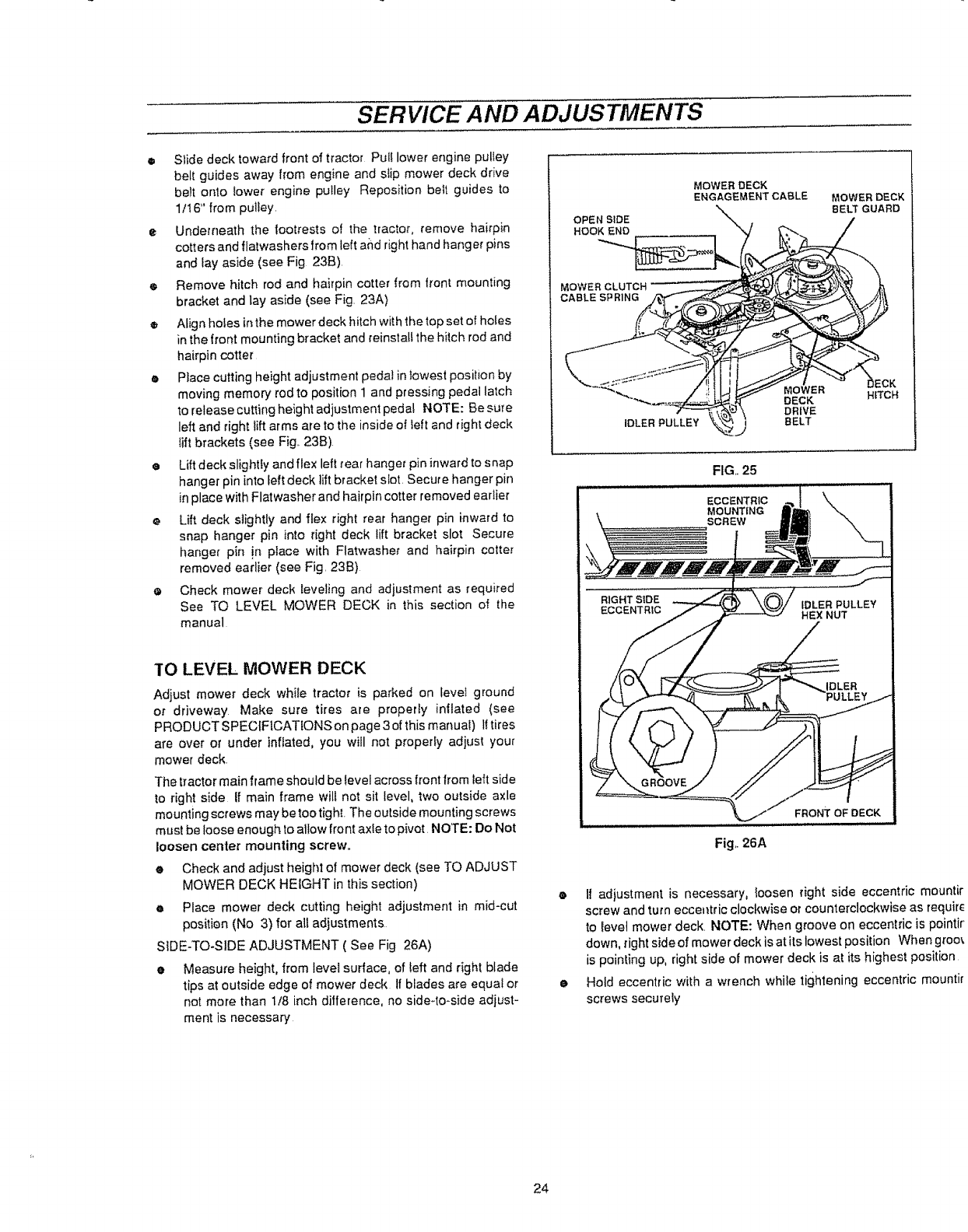
SERVICE AND ADJUSTMENTS
® Slide deck toward front of tractor Puff lower engine pulley
belt guides away from engine and slip mower deck drive
be_t onto lower engine puIley Reposition be_t guides to
1/16+' from pulley.
•Underneath the footrests of the tractor, remove hairpin
cotters and flatwashers from left and right hand hang er pins
and _ay aside (see Fig 23B).
eRemove hitch rod and hairpin cotter from trent mounting
bracket and lay aside (see Fig. 23A)
® Align holes inthe mower deck hitch with the top set of holes
in the front mounting bracket and reinstafl the hitch rod and
hairpin cotter
•Place cutting height adjustment peda_ in lowest position by
moving memory rod to position 1 and pressing pedal la',ch
to release cutting height adjustment pedal NOTE: Be sure
left and right lift arms are to the inside of Ieft and right deck
tift brackets (see Fig 23B).
• Lift deck slightly and flex left rear hanger pin inward to s nap
hanger pin into left deck rift bracket slot. Secure hanger pin
in place with Flatwasher and hairpin cotter removed earlier
•Lift deck slightly and flex right rear hanger pin inward to
snap hanger pin into right deck lift bracket slot Secure
hanger pin !n place with Flatwasher and hairpin cotter
removed earlier (see Fig. 23B)
•Check mower deck reveling and adjustment as required
See TO LEVEL MOWER DECK in this section of the
manual
MOWER DECK
ENGAGEMENTCABLE MOWERDECK
%. BELT GUARD
OPEN SIDE
HOOK END
MOWER
CABLESPRING
IDLER PULLEY
:K
MOWER
DECK H_TCH
DRWE
BELT
FIG,+ 25
TO LEVEL MOWER DECK
Adjust mower deck while tractor is parked on level ground
or driveway Make sure tires are properly inflated (see
PRODUCTSPECfF1CATtONSonpage3ofthis manual) lftires
are over or under inflated, you will not proper_y adjust your
mower deck.
The tractor main frame should be Ievel across front from teft side
to right side If main frame will not sit level, two outside axle
mounting screws may betoo tight. The outside mounting screws
must be loose enough to allow front axle to pivot. NOTE: Do Not
loosen center mounting screw.
eCheck and adjust height of mower deck (see TO ADJUST
MOWER DECK HEIGHT in this section)
• Place mower deck cutting height adjustment in mid-cut
posit{on (No 3) for all adjustments
SiDE-TO+SIDE ADJUSTMENT ( See Fig 26A)
•Measure height, from leve_ surface, of teft and right blade
tips at outside edge of mower deck If blades are equa+ or
not more than 1/8 inch difference, no side+to+side adjust-
ment is necessary
Fig,.26A
• If adiustment is necessary, !oosen right side eccentric mountir
screw and turnecce_tric clockwise or counterclockwise as requir_
to revel mower deck, NOTE: When groove on eccentric is pointir
down, rightside of mower deck is at itslowest position When groin
is pointing up, right side of mower deck is at its highest position
•Hold eccentric with a wrench while tightening eccentric mountir
screws secure{y
24
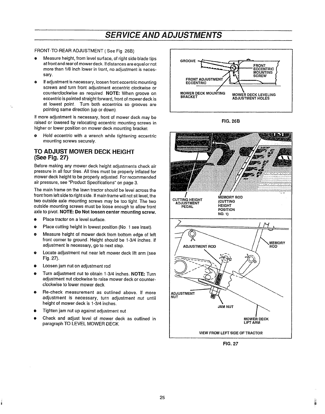
SERVICE AND ADJUSTMENTS
FRONT_TO-REAR ADJUSTMENT ( See Fig 26B)
•Measure height, from level surface, of right side blade tips
at front and rearof mower deck. Ifdistances are equalor not
more than lib inch lower in front, no adiustment is neces-
sary..
o If adjustment is necessary, loosen front eccentric mounting
screws and turn front adjustment eccentric clockwise or
counterclockwise as required. NOTE: When groove on
eccentric is pointed straight forward, front of mower deck is
at lowest point. Turn both eccentrics so grooves are
pointing same direction (up or down).
If more adjustment is necessary, front of mower deck may be
raised or lowered by relocating eccentric mounting screws in
higher or lower position on mower deck mounting bracket.
e Hold eccentric with a wrench while tightening eccentric
mounting screws securely..
TO ADJUST MOWER DECK HEIGHT
(See Fig. 27)
Before making any mower deck height adjustments check air
pressure in all four tires.. All tires must be properly inflated for
mower deck height to be properly adiusted.. For recommended
air pressure, see "Product Specifications" on page 3o
The main frame on the lawn tractor should be level across the
front from left side to right side..If main frame will not sit level, the
two outstde axle mounting screws may be too tight. The two
outside mounting screws must be loose enough to allow front
axle to pivot, NOTE: Do Not loosen center mounting screw.
•Place tractor on alevel surface..
o
@
O
O
o
Place cutting height in lowest position (No. t see inset).
Measure height of mower deck from bottom edge of left
front corner to ground. Height should be t-3/4 inches, if
adjustment is necessary, go to next step..
Locate adjustment nut near left mower deck lift arm (see
Fig. 27)°
Loosen jam nut on adjustment rod
Turn adjustment nut to obtain 1-3/4 inches. NOTE: Turn
adjustment nut clockwise to raise mower deck or counteF
clockwise to lower mower deck.
eRe-check measurement as outlined above.. If more
adjustment is necessary, turn adjustment nut until
height ol mower deck is 1-3/4 inches..
•Tighten jam nut up against adjustment nut
•Check and adjust level of mower deck as outlined in
paragraph TO LEVEL MOWER .DECK.
QROOVE__ _ , _,
L__ __ FRONT /
'_''"_,,,._.._._Z_IM_I_ _ ECCENTRIC l
_,,'T"'8_.1t MOUNTING )
/,,_ u\! t SCREW |
FRO_fT ADJUSTMENT ./'_ '_.=,_ }
EC CENT RIC /}'_-""_\
MOWER DECK MOUNTING MOWER DECK LEVELIN G
BRACKET ADJUSTMENT HOLES
FIG. 26B
MEMORY ROD
CUTTING HEIGHT (CUTTING
ADJUSTMENT
PEDAL HEIGHT
PosmoN
NO.,t)
VIEMORY
ADJUSTMENT
NUT
JAM NUT
MOWER DECK
LIFT ARM
ViEW FROM LEFT SIDE OF TRACTOR
FIG. 27
25
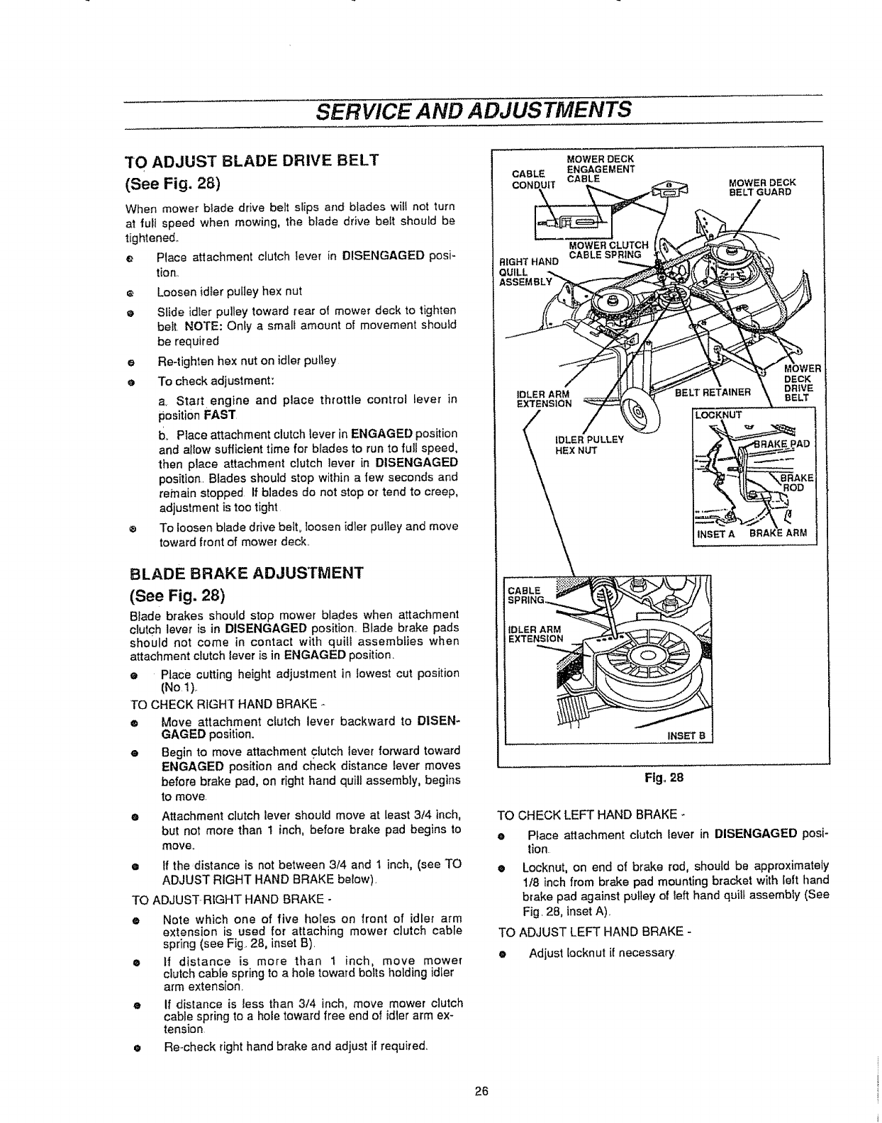
SERVICE AND ADJUSTMENTS
TO ADJUST BLADE DRIVE BELT
(See Fig. 28)
When mower blade drive belt slips and blades wilt not turn
at full speed when mowing, the blade drive belt should be
tightened,,
e Place attachment clutch lever in DISENGAGED posi-
tion,,
Loosen idler pulley hex nut
eSlide idler pulley toward rear of mower deck to lighten
belt NOTE: Only a small amount of movement should
be required
eRe-tighten hex nut on idler pultey
e To check adjustment:
a. Start.engine and place throttle control lever in
position FAST
b. Place attachment clutch{ever inENGAGED position
and allow sufficient time for blades to run to fuJlspeed,
then place attachment clutch ]ever in DISENGAGED
position. Blades should stop within a few seconds and
remain stopped If blades do not stop or tend to creep,
adjustment is too tight
To loosenblade drive belt0loosen idler pulley and move
toward front of mower deck..
BLADE BRAKE ADJUSTMENT
(See Fig. 28)
Blade brakes should stop mower blades when attachment
clutch lever is in DISENGAGED position. Blade brake pads
should not come in contact with quill assemblies when
attachment clutch lever is in ENGAGED position.
ePlace cutting height adjustment in lowest cut position
(No,t),.
TO CHECK RIGHT HAND BRAKE
®Move attachment clutch lever backward to DISEN-
GAGED position.
e Begin to move attachment clutch lever forward toward
ENGAGED position and check distance lever moves
before brake pad, on righthand quitl assembly, begins
to move.
Attachment clutch lever should move at least 3t4 inch,
but not more than 1 inch, before brake pad begins to
move..
•If the distance is not between 3/4 and t inch, (see TO
ADJUST RIGHT HAND BRAKE below).
TO ADJUST RIGHT HAND BRAKE -
eNote which one of five holes on front of idler arm
extension is used for attaching mower dutch cable
spring (see Fig..28, inset B).
e If distance is more than t inch, move mower
clutch cable spring to ahole toward bolts holding idler
arm extension.
If distance is less than 3/4 inch, move mower clutch
cable spring to a hole toward free end of idler arm ex-
tension
• Re=checkright hand brake and adjust if required..
CABLE
MOWER DECI(
ENGAGEMENT
CABLE MOWER DECK
BELT"GUARD
RIGHT HAND
QUILL
MOWER CLUTCH
CABLE SPRING
iDLER ARM
EXTENSION
IDLER PULLEY
HEX NUT
LOCI(NUT
_R
DECK
DRIVE
INSET B
Fig. 28
TO CHECK LEFT HAND BRAKE
ePlace attachment cSutch lever in DISENGAGED posi-
tion
oLocknut, on end of brake rod, should be approximately
1/8 inch from brake pad mounting bracket with left hand
brake pad against pulley of left hand quill assembly (See
Fig. 2B, inset A).
TO ADJUST LEFT HAND BRAKE-
•Adjust [ocknutif necessary
26
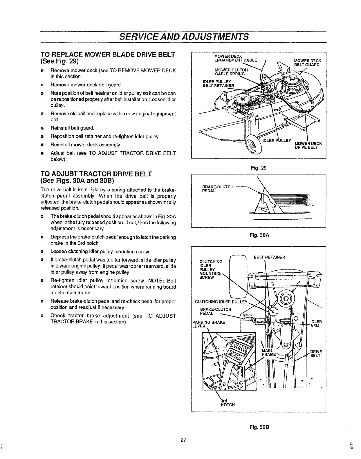
SERVICE AND ADJUSTMENTS
TO REPLACE MOWER BLADE DRIVE BELT
(See Fig+ 29)
eRemove mower deck (see TO REMOVE MOWER DECK
in this section,
e Remove mower deck belt guard
•Note position of belt retainer on idler pulley so it can be can
be repositioned properly after belt installation Loosen idler
pulley.,
®Remove old belt and replace with a new original equipment
belt
eReinstall belt guard,.
@Reposition belt retainer and re-tighten idler pulley,,
•Reinstatl mower deck assembly,
•Adjust belt (see TO ADJUST TRACTOR DRIVE BELT
below)+
TO ADJUST TRACTOR DRIVE BELT
(See Figs. 30A and 30B)
The drive belt is kept tight by a spring attached to the brake-
clutch pedal assembly When the drive beft is properly
adjusted, the brake+clutch pedal shoutd appear as shown infully
released position.,
®The brake-clutch pedal should appear as shown in Fig, 30A
when in the futly reteased position, iI not, then the foftowing
adjustment is necessary.
eDepress the brake-clutch pedal enough to latch the parking
brake inthe 3rd notch
eLoosen clutching idler pulley mounting screw,
eIf brake+clutch pedal was too far forward, slide idler pulley
intoward engine pulley, If pedal was too far rearward, slide
idlerpultey away from engine pulley.
eRe-tighten idler pulley mounting screw., NOTE: Belt
retainer should point toward position where running board
meets main frame,
•Release brake+clutch pedal and re-check pedalfor proper
position and readjust if necessary.
eCheck tractor brake adjustment (see TO ADJUST
TRACTOR BRAKE in this section),
MOWER DECK
ENGAGEMENT CABLE
MOWER CLUTCH
CABLE SPRING
IDLER PULLEY
BELT RETAINER
PULLEY MOWER DECK
DRIVE _BELT
Fig+29
BRAKE,-CLUTCH
PEDAL
Fig, 30A
BELT RETAINER
CLUTCHING
IDLER
PULLEY
MOUNTING
SCREW
CLUTCHING iDLER PULLEY
BRAKE-CLUTCH
PEDAL
PARKING BRAKE
LEVER
3rd
NOTCH
27
Fig,,30B
i,
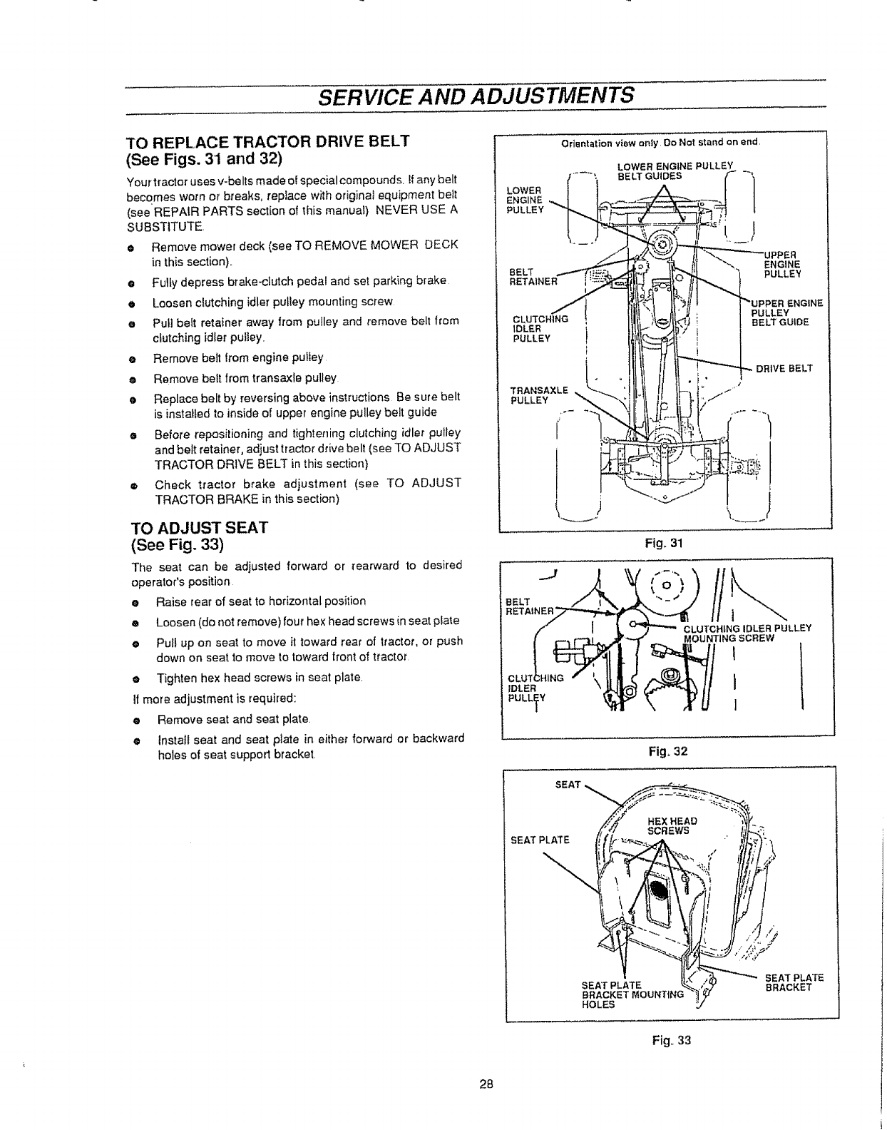
SERVICE AND ADJUSTMENTS
TO REPLACE TRACTOR DRIVE BELT
(See Figs. 31 and 32)
Your tractor uses v-be Its made of special compounds, if any belt
becomes worn or breaks, replace will'} original equipment be_t
(see REPAIR PARTS section of this manual) NEVER USE A
SUBSTITUTE.
e Remove mower deck (see TO REMOVE MOWER DECK
in this section).
•Fully depress brake-clutch pedal and set parking brake
• Loosen clutching idler pulley mounting screw
• Pull belt retainer away from pulley and remove belt from
clutching idler pulley.
eRemove belt trom engine pulley
e Remove belt from transaxle pulley
• Replace belt by reversing above instructions Be sure belt
is installed to inside of upper engine pulley belt guide
e Before repositioning and tightening clutching idler pulley
and belt retainer, adjust tractor drive belt (see TO ADJUST
TRACTOR DRIVE BELT in this section)
®Check tractor brake adjustment (see TO ADJUST
TRACTOR BRAKE in this section)
TO ADJUST SEAT
(See Fig. 33)
Tile seat can be adjusted forward or rearward to desired
operator's position
eRaise rear of seat to horizontal position
®Loosen (do not remove) four hex head screws in seat plate
ePull up on seat to move it toward rear of tractor, or push
down on seat to move to toward tront of tractor
•Tighten hex head screws in seat plate.
If more adjustment is required:
eRemove seat and seat plate.
•Install seat and seat plate in either forward or backward
holes of seat support bracket.
Orientation view onty Do Not stand on end,
LOWER ENGINE PULLEY
/.... ; BELT GUIDES f _,
LOWER/ I A t I
ENGINE ,,_ ii..... _--J l
PULLEY
./-_1__ _ I(( "',,_ ENGINE
'l)_,
/t\, PULLEY
CLUTCHING {It )
rULER' t ; LTGU,D
Fig_ 31
IDLER
PULLEY
CLUTCHINGIDLER PULLEY
MOUNTINGSCREW
I
I
Fig. 32
SEAT
HEXHEAD
SCREWS
SEATPLA3"E
SEAT PLATE _"_"_
BRACKETMOUNTING
HOLES
SEAT PLATE
BRACKET
28
Fig. 33
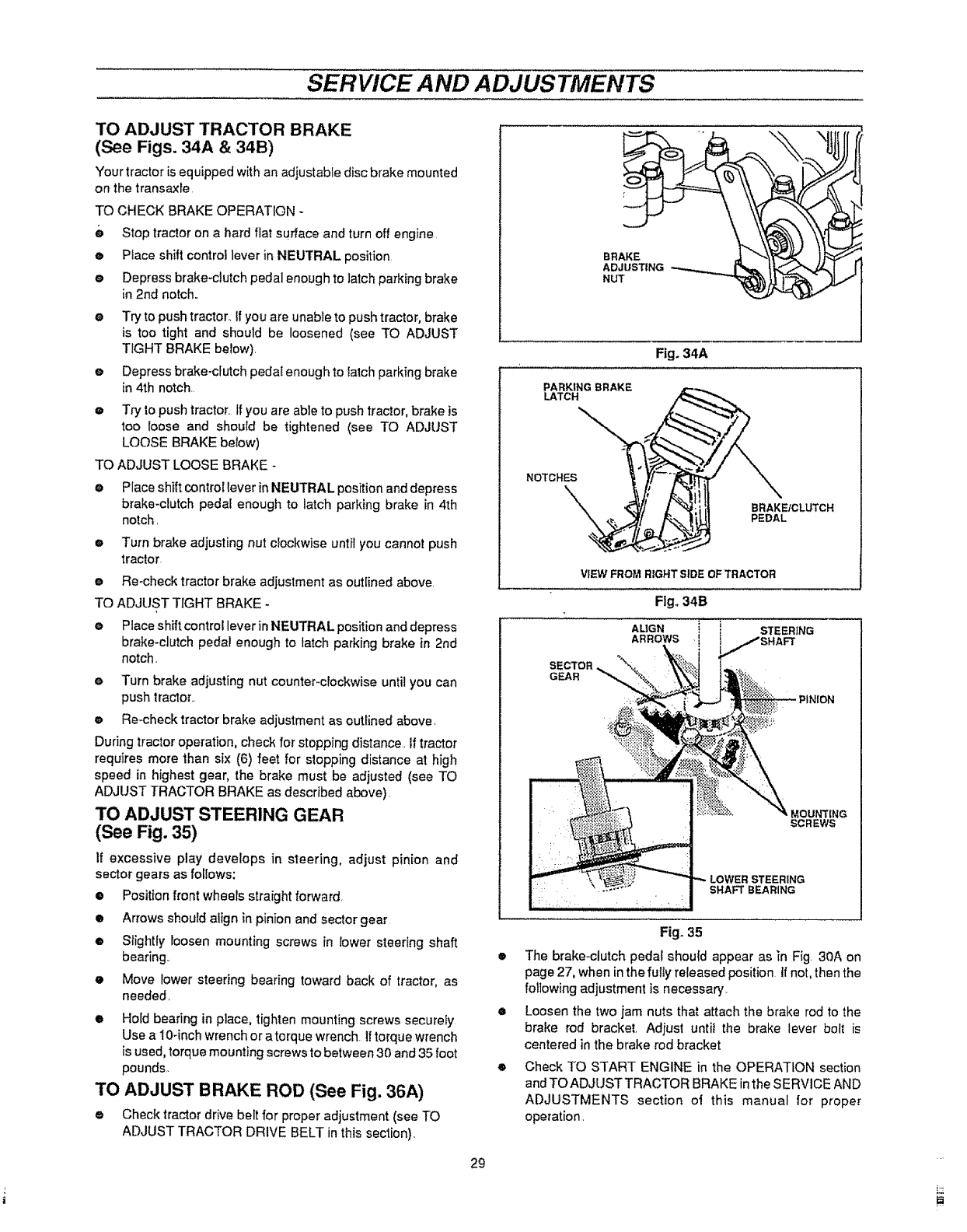
SERVICE AND ADJUSTMENTS
TO ADJUST TRACTOR BRAKE
(See Figs. 34A & 34B)
Your tractor is equipped with an adjustable disc brake mounted
on the transaxle
TO CHECK BRAKE OPERATION *
0 Stop tractor on a hard flat surface and turn off engine.
• Place shift control lever in NEUTRAL position
eDepress brake-clutch pedal enough to latch parking brake
in 2rid notch,,
O
o
o
TO
o
Try to push tractor.. If you are unable to push tractor, brake
is too tight and should be loosened (see TO ADJUST
TIGHT BRAKE below).
Depress brake-clutch pedaI enough to _atchparking brake
in 4th notch.
Try to push tractor. If you are able to push tractor, brake is
too loose and should be tightened (see TO ADJUST
LOOSE BRAKE below)
ADJUST LOOSE BRAKE -
Place shift control lever in NEUTRAL position and depress
brake-clutch pedal enough to latch parking brake in 4th
notch.
eTurn brake adjusting nut clockwise until you cannot push
tractor.
e Re-check tractor brake adjustment as outlined above.
TO ADJUST TIGHT BRAKE -
e Place shift control lever in NEUTRAL position and depress
brake-clutch pedal enough to latch parking brake in 2nd
notch.
eTurn brake adjusting nut counter-clockwise until you can
push tractor.,
eRe-checktractor brake adjustment as outlined above.
During tractor operation, check for stopping distance. If tractor
requires more than six (6) feet for stopping distance at high
speed in highest gear, the brake must be adjusted (see TO
ADJUST TRACTOR BRAKE as described above).
TO ADJUST STEERING GEAR
(See Fig. 35)
If excessive play develops in steering, adjust pinion and
sector gears as follows:
•Position front wheels straight forward
•Arrows should align in pinion and sector gear
•Siightly loosen mounting screws in lower steering shaft
bearing..
•Move lower steering bearing toward back of tractor, as
needed,
• Hold bearing in place, tighten mounting screws securely.
Use a 10-inch wrench or a torque wrench iftorque wrench
is used, torque mounting screws to between 30 and 35 foot
pounds.
TO ADJUST BRAKE ROD (See Fig. 36A)
® Check tractor drive belt for proper adjustment (see TO
ADJUST TRACTOR DRIVE BELT in this section).
29
BRAKE
ADJUSTING
NUT
Fig. 34A
PARKING BRAKE
LATCH
NOTCHES
BRAKEICLUTCH
PEDAL
VIEW FROM RIGHT SIDE OF TRACTOR
Ftg_ 34B
ALIGN iSTEERING
ARROWS
,MOUNTING
SCREWS
SHAFT BEARING
Fig° 35
• The brake-clutch pedal shouid appear as _n Fig, 30A on
page 27, when in the fully released position ifnot, thenthe
following adjustment is necessary.
eLoosen the two jam nuts that attach the brake rod to the
brake rod bracket, Adjust until the brake lever bolt is
centered in the brake rod bracket
•Check TO START ENGINE in the OPERATION section
and TO ADJUST TRACTOR BRAKE in the SERVICE AND
ADJUSTMENTS section of this manual for proper
operation.
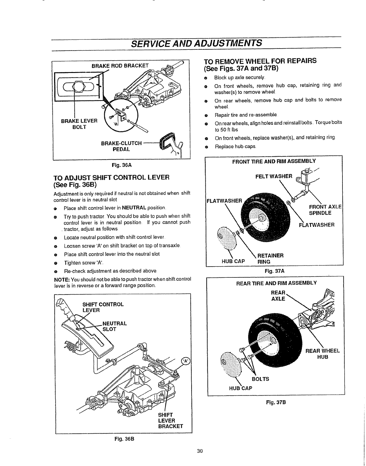
SERVICE AND ADJUSTMENTS
Fig. 36A
TO ADJUST SHIFT CONTROL LEVER
(See Fig. 36B)
Adjustmentis only requiredif neutra! is not obtainedwhen shift
control lever is in neutral slot
oPlace shift control lever in NEUTRAL position,
e Try to push tractor "Youshould be able to push when shift
control lever is in neutral position If you cannot push
,,tractor, adjust as fotiows
eLocate neutra! position with shift control lever
eLoosen screw'A' on shift bracket on top of transaxle
ePlace shift control lever into the neutral slot
eTighten screw 'AL
eRe-check adjustment as described above
NOTE: You should not be able to push tractor when shift control
lever iSin reverse or a forward range position,,
LEVER
BRACKET
Fig. 36B
TO REMOVE WHEEL FOR REPAIRS
(See Figs. 37A and 37B)
eBlock up axle securely,
eOn front wheels, remove hub cap, retaining ring and
washer(s) to remove wheel,
•On rear wheels, remove hub cap and bolts to remove
wheel,
eRepair tire and re-assemble
eOn rear wheels, align holes and reinstaflbolts, Torque bolts
to 50 ft Ibs
•On front wheels, replace washer(s), and retaining ring
e Replace hubcaps.
FRONT TIRE AND RIM ASSEMBLY
jJ
FELT WASHER
FLATWASHER
FRONT AXLE
SPINDLE
FLATWASHER
RETAINER
HUB CAP RING
Figo37A
REAR TIRE AND RIM ASSEMBLY
REAR
AXLE
REAR WHEEL
HUB
BOLTS
HUB CAP
Fig. 37B
30
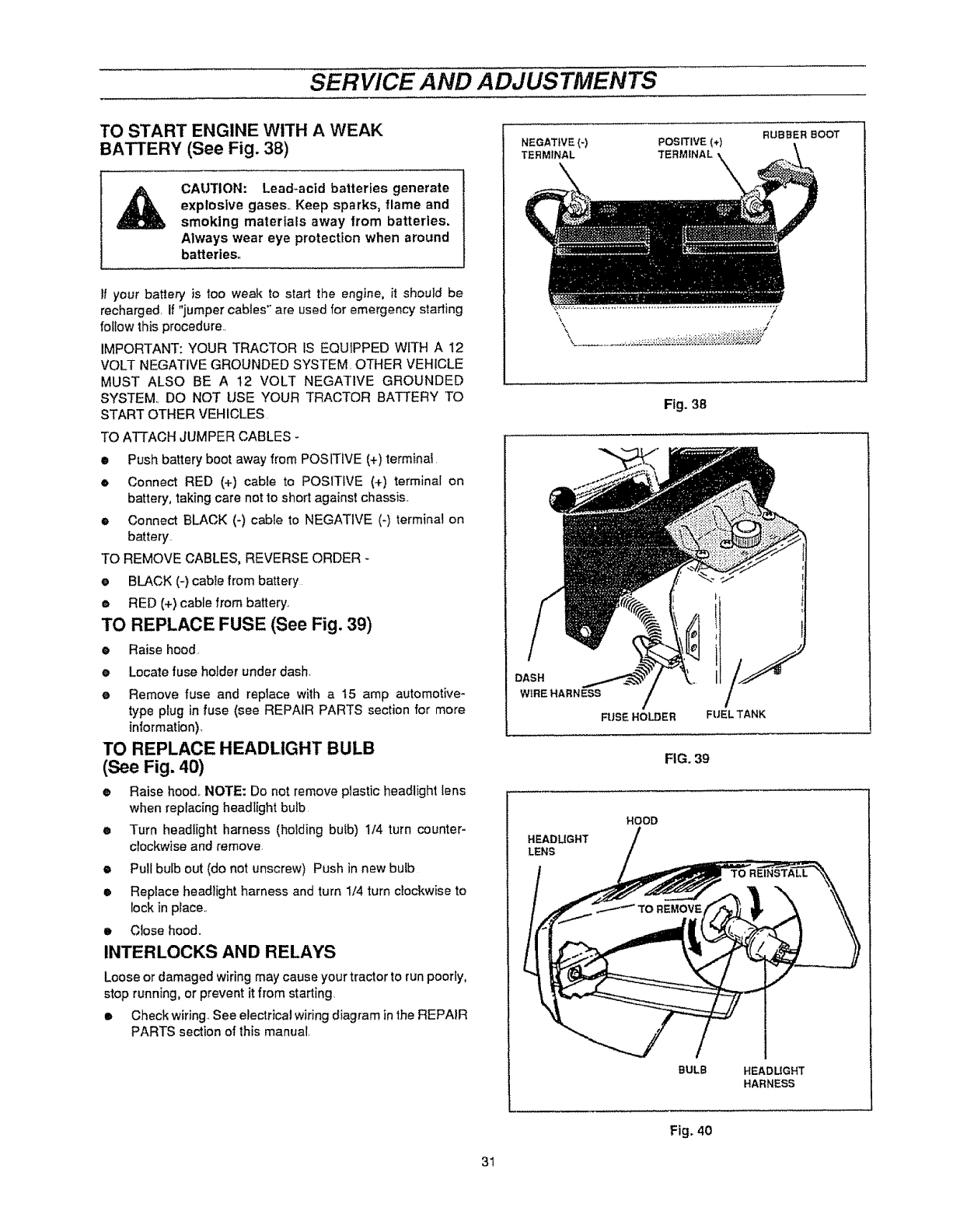
SERVICE AND ADJUSTMENTS
TO START ENGINE WITH AWEAK
BATTERY (See Fig. 38)
CAUTION: Lead-acid batteries generate
explosive gases, Keep sparks, flame and
smoking materials away from batteries.
Always wear eye protection when around
batteries°
II your battery is too weak to start the engine, it should be
recharged. If "jumper cables" are used for emergency starting
follow this procedure..
IMPORTANT: YOUR TRACTOR IS EQU1PPED WITH A 12
VOLT NEGATIVE GROUNDED SYSTEM. OTHER VEHICLE
MUST ALSO BE A 12 VOLT NEGATIVE GROUNDED
SYSTEM. DO NOT USE YOUR TRACTOR BATTERY TO
START OTHER VEHICLES
TO ATTACH JUMPER CABLES -
•Push battery boot away from POSITIVE (+) terminal.
eConnect RED (+) cable to POSITIVE (+) terminal on
battery, taking care not to short against chassis..
• Connect BLACK (-) cable to NEGATIVE (-) terminal on
battery.
TO REMOVE CABLES, REVERSE ORDER -
eBLACK (-) cabte from battery
eRED (+)cable from battery.
TO REPLACE FUSE (See Fig. 39)
•Raise hood.
e Locate fuse holder under dash,
e Remove fuse and replace with a t5 amp automotive-
type plug in fuse (see REPAIR PARTS section for more
intormation),
TO REPLACE HEADLIGHT BULB
(See Fig. 40)
•Raise hood, NOTE: Do not remove plastic headlight lens
when replacing headlight bulb
e Turn headlight harness (holding bulb) !/4 turn counter-
clockwise and remove
• Pull bulb out (do not unscrew) Push in new bulb
e Replace headlight harness and turn 1/4 turn clockwise to
lock in place..
eClose hood..
INTERLOCKS AND RELAYS
Loose or damaged wiring may cause your tractor to run poorly,
stop running, or prevent it from starting.
• Check wiring See electrical wiring diagram in the REPAIR
PARTS section of this manual.
NEGATIVE {-)
TERMINAL POSITIVE(*)
TERMINAL
RUBBER BOOT
Fig. 38
DASH
W1REHARNESS
FUSE HOLDER FUELTANK
FIG. 39
HOOD
HEADLIGHT
LENS
BULB HEADUGHT
HARNESS
Fig. 40
31
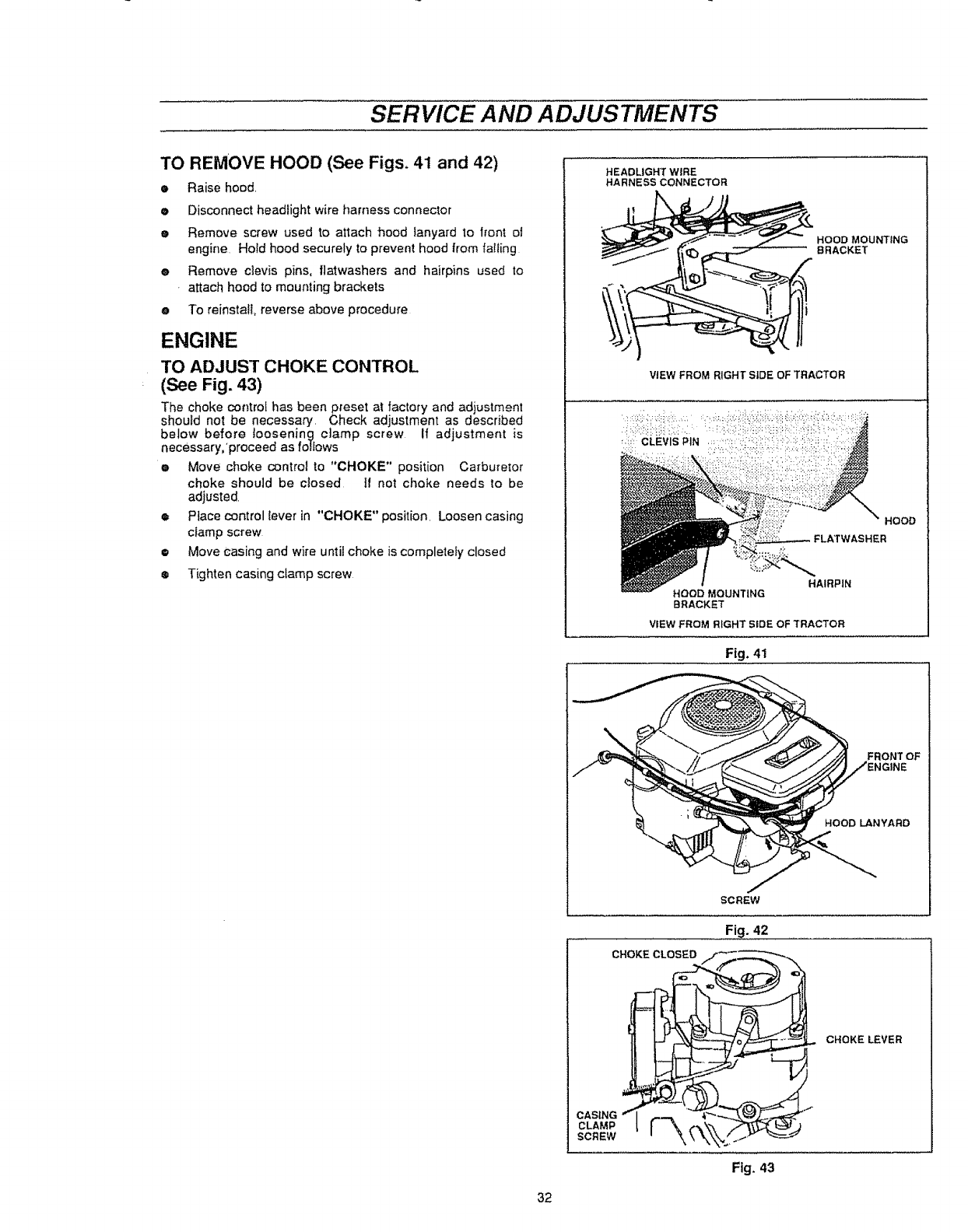
SERVICE AND ADJUSTMENTS
TO REMOVE HOOD (See Figs. 41 and 42)
•Raise hood.
eDisconnect headlight wire harness connector
eRemove screw used to attach hood tanyard to front of
engine Hold hood securely to prevent hood from failing
eRemove clevis pins, flatwashers and hairpins used to
attach hood to mounting brackets
eTo reinstall reverse above procedure
ENGINE
TO ADJUST CHOKE CONTROL
(See Fig. 43)
The choke control has beenpreset at factory and adjustment
should not be necessary, Check adjustment as described
below before loosening clamp screw If adjustment is
necessary,proceed as foJ!ows
•Move choke control to '*CHOKE" position Carburetor
choke should be closed tf not choke needs to be
adjusted.
•Place control lever in "CHOKE" position, Loosen casing
ciamp screw
•Move casing and wire until choke is completely closed
®Tighten casing clamp screw
HEADLIGHT WIRE
HARNESS CONNECTOR
HOOD MOUNTING
BRACKET
ViEW FROM RIGHT SiDE OF TRACTOR
HOOD
FLATWASHER
HAIRPIN
HOOD MOUNTING
BRACKET
VIEW FROM RIGHT SIDE OF TRACTOR
F|g, 41
FRONT OF
HOOD LANYABD
SCREW
Fig. 42
CHOKE CLOSED
CHOKE LEVER
32
CLAMP
SCREW
Fig. 43
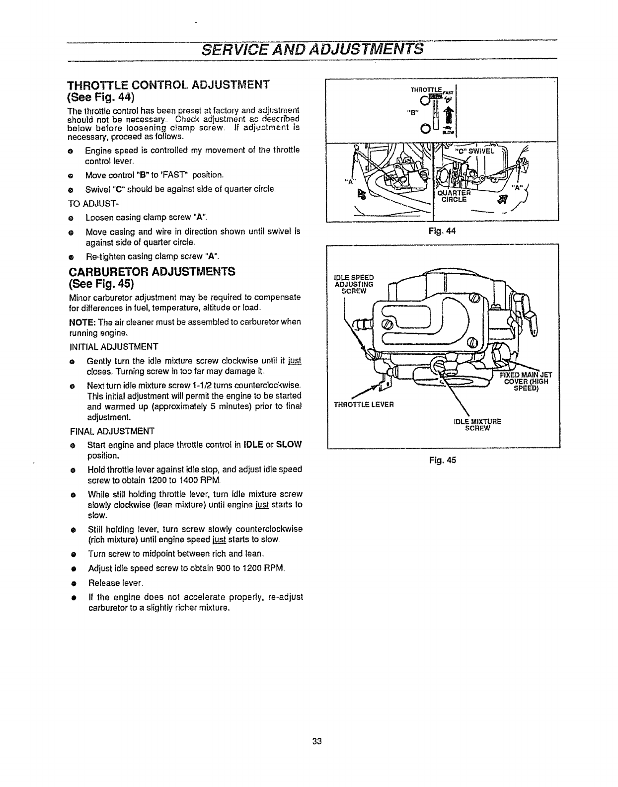
SERVICE AND ADJUSTMENTS
THROTTLE CONTROl. ADJUSTMENT
(See Fig. 44)
The throttle control has been preset at factory andadjustment
should not be necessary. Check adjustment a_'_"described
below before loosening clamp screw. If adj_._tment is
necessary, proceed as foltows.
o Engine speed is controlled my movement of the throttle
control lever..
o Move control "B" to 'FAST" position..
®Swivel"C" should be against side of quarter circle.
TO ADJUST-
eLoosen casing cramp screw "A"o
eMove casing and wire in direction shown until swivel is
against side of quarter circle_
• Re-tighten casing clamp screw "A"..
CARBURETOR ADJUSTMENTS
(See Fig. 45)
Minor carburetor adjustment may be required to compensate
for differences in fuel, temperature, altitude or load.
NOTE: The air cleaner must be assembled to carburetor when
runningengine..
INITIAL ADJUSTMENT
®Gently turn the id]e mixture screw clockwise until it
closes. Turning screw intoo far may damage it.
eNext turn idle mixture screw 1-1/2 turns counterclockwise.
This initial adjustment will permit the engine to be started
and warmed up (approximately 5minutes) prior to final
adjustment.
FINAL ADJUSTMENT
eStart engine and place throttle control in IDLE or SLOW
position.
eHold throttle lever against idle stop, and adjust idle speed
screwto obtain 1200 to i400 RPM
• While still holding throttle lever, turn idle mixture screw
slowly clockwise (lean mixture) until engine j.q_ starts to
slow.
•Still holding lever, turn screw slowly counterclockwise
(rich mixture) until engine speed "ujg_starts to slow.
•Turn screw to midpoint between rich and lean.
•Adjust idle speed screw to obtain 900 to 1200 RPM
•Release lever.
•If the engine does not accelerate properly, re-adjust
carburetorto a slightly richer mixture.
0
CIRCLE
Fig, 44
IDLE SPEED
ADJUSTING
SCREW
THROTTLE LEVER
FIXED MAIN JET
COVER(HIGH
SPEED)
IDLE MIXTURE
SCREW
Fig° 45
33
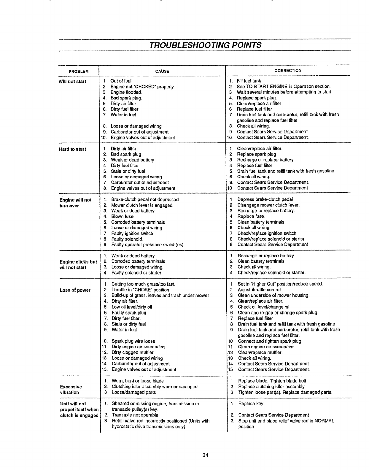
TROUBLESHOOTING POIAITS
PROBLEM
Will not start 1
2
3
4,
5,.
6+
7.
a
9.
10..
Hard to start 1.
2,
3.
4.
5
6
7
8,
Engine will not 1.
turn over 2
3.
4
5.
6
7,
8,
9,
t,
Engine clicks but 2,,
wallnot start 3
4
1
Loss of power 2
3.
4+
5
6
7
8,
9
t0
11
12,
!3
14
15
Excessive 2,
vibration 3
Unit will not 1.
propel itself when
clutch is engaged 2.
3
CAUSE
Out of fuel
Engine not "CHOKED" properly.
Engine flooded.
Bad spark plug..
Dirty air filter
Dirty fuelfilter
Water infueL.
Loose or damaged wiring
Carburetor out of adjustment
Engine valves out of adjustment
Dirtyair filter
Bad spark plug
Weak or dead batter:/
Dirty fuel fiiter
Stale or dirty fuel
Loose or damaged wiring
Carburetor out of adjustment
Engine valves out of adjustment
Brake-clutch pedal not depressed
Mower clutch lever is engaged
Weak or dead battery.
Blown fuse
Corroded battery terminals
Loose or damaged wiring
Faulty ignition swatch
Faulty solenoid
Faulty operator presence switch(es)
Weak or dead battery
Corroded battery terminals
Loose or damaged widng
Faulty solenoid or starter.
Cutting too much grassttoo fast.
Throttle in "CHOKE" position.
Build-up of grass, leaves and trash under mower
Dirtyair filter.
Lowoillevelldirtyoil
Faultysparkplug
Dirtyfuelfilter
Staleordirtj fuel
Waterinfuel
Spark plug wire loose
Dirty engine air screen/fins
Dirty clogged muffler.
Loose or damaged wiring
Carburetol' out of adjustment
Engine valves out of adjustment
Worn, bent or loose blade
Clutching idler assembly worn or damaged
Loose/damaged parts
Sheared or missing engine, transmission or
transaxie pulley(s) key,
Transaxte not operable,
Relief valve rod incorrectly positioned (Units with
hydrostatic ddve transmissions only)
CORRECTION
1. Fil! fuel tank
2. See TO START ENGINE in Operation section
3Wait several minutes before attempting to start
4.. Replace spark plug
5.. Clearffreplace air rifler
6 Replace fuel filter
7 Drain fuel tank and carburetor, refill tank with fresh
gasoline and replace fuel fi_ter
8Check all widng,
gContact Sears Service Department,
10 Contact Sears Service Department,
t, C]earVrep]ace air filter
2 Replace spark plug
3 Recharge or replace battery
4+ Reptace fuel filter.
5 Drain fuel tank and refil! tank with fresh gasoline
6. Check all wiring.
9. Contact Sears Service Department..
t0 Contact Sears Service Department
1 Depress brake+clutchpedal
2Disengage mower clutch Iever
3 Recharge or replace battery..
4 Replace fuse
5Clean battery terminals
6Check all wiring
7 CheckJrepiace ignition swatch
8 Check/replace solenoid or starter
9 Contact Sears Service Department.
1 Recharge or replace battery.
2Clean battery terminals
3Check all wiring
4Check/replace solenoid or starter
1 Set [n "Higher Cut" pos[tionfreduce speed
2Adjust throttle control
3Clean underside of mower housing
4CIearffrep]ace air filter.
5 Check oil level/change oil
6Clean and re-gap or change spark plug
"7 Replace fuel filter,
8Drain fuel tank and refill tank with trash gasoline
9 Drain fuel tank and carburetor, refiU tank with fresh
gasoline and replace fuet filter
10 Connect and tighten spark plug
1t Clean engine air screen/fins.
12 Clean/repEace muffler.
13 Check all wiring.
14 Contact Sears Service Department
t5 Contact Sears Service Department
1 Replace blade Tighten blade boil
2 Replace clutchingidler assembly.
3 Tighten loose part(s). Replace damaged parts
1.+ Replace key
2Contact Sears Service Department
3Stop unit and place relief valve rod in NORMAL
position
34
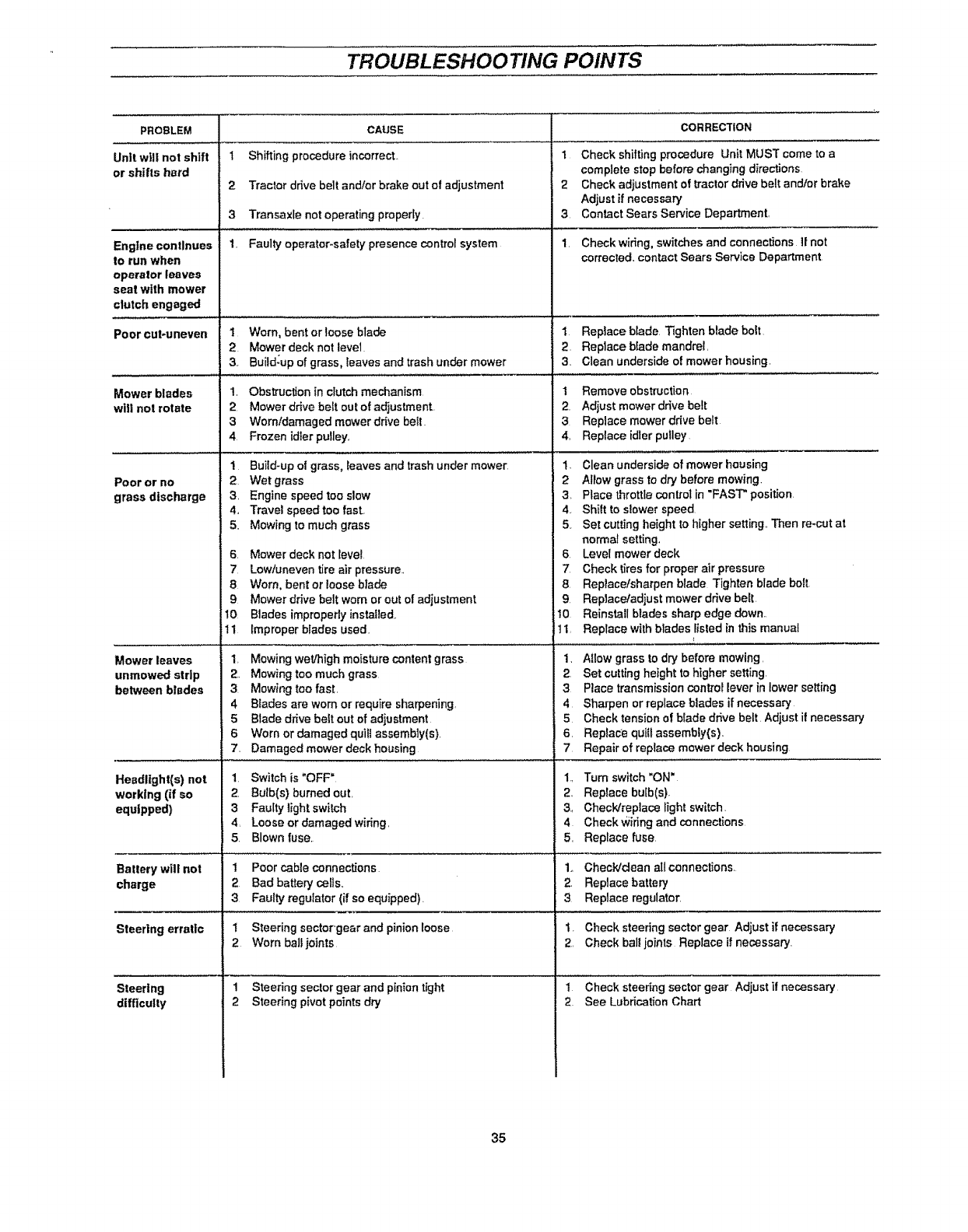
TROUBLESHOOTING POINTS
PROBLEM
Unit will not shift
or shifts hard
Engine continues
to run when
operator leaves
seal with mower
clutch engaged
Poorcut-uneven
Mower blades
will not rotate
Poor or no
grass discharge
Mower leaves
unmowed strip
between blades
Headlight(s) not
working (if so
equipped)
Batterywill not
charge
Steering erratic
Steering
difficulty
CAUSE
1 Shifting procedure incorrect.
2Tractor ddve belt and/or brake out of adjustment
3 Transaxle not operating properly.
1. Faulty operetor_safety presence control system
1 Worn, bent or loose blade
2, Mower deck not level.
3, Build;up of grass, leaves and trash under mower
1. Obstruction in clutch mechanism
2Mower drive belt out of adjustment
3Worn/damaged mower drive bell.
4 Frozen idler pulley,
1
2 Wet grass
3, Engine speed too slow
4,, Travel speed too fast.
5. Mowing to much grass
Build-up el grass, leaves and trash under mower
S.
7
8
9
10
11
Mower deck not level
Low/uneven tire air pressure..
Worn, bent or loose blade
Mower drive belt worn or out of adjustment
Blades improperly installed,
Improper blades used.
1, Mowing wet/high moisture content grass
2, Mowing too much grass
3. Mowing too fast.
4 Blades are worn or require sharpening,
5 Blade drive belt out of adiustment
6Worn or damaged quifi assembly(s).
7. Damaged mower deck housing
1Switch is "OFF"
2. Bulb(s) burned out,
3 Faulty light switch
4, Loose or damaged wiring,
5. Blown fuse,
1 Poor cable connections
2Bad battery cells,,
3Faulty regulator (if so equipped).
! Steering sector'gear and pinion loose
2Worn ball joints
1 Steering sector gear and piniontight
2Steering pivot points dry
CORRECTION
1 Check shifting procedure Unit MUST come to a
complete stop before changing directions
2 Check adjustment of traclor drive belt and/or brake
Adjust if necessary
3. Contact Sears Service Department,
1. Checkwidng, switches and connections I! not
corrected, contact Sears Service Department
1 Replace blade Tighten blade bolt
2, Replace blade mandrel,
3, Clean underside of mower housing.
1Remove obstruction
2. Adjust mower drive belt
3 Replace mower drive belt
4, Replace idler pulley
1. Clean underside of mower housing
2Allow grass to dry before mowing,
3, Place throttle control in "FAST" position
4.. Shift to slower speed
5, Set cutting height to higher setting,, Then re-cut at
normal setting,
6, Level mower deck
7, Check tires for proper air pressure
8, Replacetsharpen blade Tighten blade bol!
9. Replace/adiust mower drive belt
!0 Reinstall blades sharp edge down,,
tIReplace with blades fisled in this manual
1, Allow grass to dry before mowing,
2Set cutting height to higher setting,
3Place transmission control lever in lower setting
4Sharpen or replace blades if necessary
5 Check tension of blade drive belt Adjust if necessary
6, Replace quill assembly(s),
7 Repair of replace mower deck housing
1, Tum switch "ON"
2Replace bulb(s)_
3, ChecWreplace light switch,
4Check Wiring and connections
5, Replace fuse,
1,. Check/dean all connections.
2. Replace battery
3Replace regulator.
1. Check steering sector gear Adjust if necessary
2, Check ball joints Replace if necessary.
1 Check steering sector gear Adjust il necessary
2 See Lubrication Chart
35
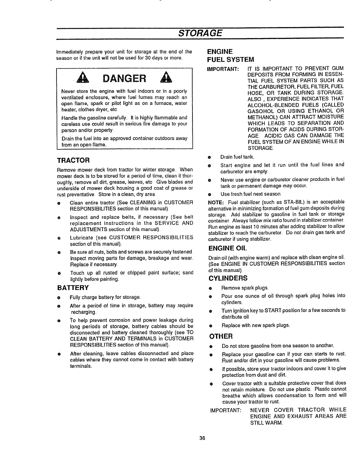
STORAGE
.................... i i i
Immediately prepare your unit for storage at the end of the
Season or if the unit will not be used for 30 days or more..
DANGER
Never store the engine with fuel indoors or in a poorly
ventilated enclosure, where fuel fumes may reach an
open flame, spark or pilot light as on a furnace, water
heater, clothes dryer, etc.
Handle the gasoline carefully. It is highly flammable and
careless use could result in serious fire damage to your
person and/or property.
Drain the fuel into an approved container outdoors away
from an open flame.
TRACTOR
Remove mower deck from tractor for winter storage When
mower deck is to be stored for a period of time, clean it thor-
oughly, remove all dirt, grease, ieaves, etc Give blades and
underside of mower deck housing a good coat of grease or
rust preventative Store in a clean, dry area
e Clean entire tractor (See CLEANING in CUSTOMER
RESPONSIBILITIES section of this manual).
®Inspect and replace belts, if necessary (See belt
replacement instructions in the SERVICE AND
ADJUSTMENTS section of this manuat).
• Lubricate (see CUSTOMER RESPONSIBILITIES
section of this manual).
e Be sure all nuts, botts and screws are securely fastened.
Inspect moving parts for damage, breakage and wear..
Reprace if necessary,.
eTouch up all rusted or chipped paint surface; sand
lightly before painting_
BATTERY
o
o
Fufly charge battery for storage..
After a period of time in storage, battery may require
recharging,
eTo hetp prevent corrosion and power teakage a'uring
long periods of storage, battery cables should be
disconnected and battery cleaned thoroughly (see TO
CLEAN BATTERY AND TERMINALS in CUSTOMER
RESPONSIBILITIES section of this manual)._
•After cleaning, leave cabEes disconnected and ptace
cables where they cannot come in contact with battery
terminals.
ENGINE
FUEL SYSTEM
IMPORTANT: IT IS IMPORTANT TO PREVENT GUM
DEPOSITS FROM FORMING IN ESSEN-
TIAL FUEL SYSTEM PARTS SUCH AS
THE CARBURETOR, FUEL FILTER, FUEL
HOSE, OR TANK DUR,ING STORAGE.
ALSO ,EXPERIENCE INDICATES THAT
ALCOHOL-BLENDED FUELS (CALLED
GASOHOL OR USING ETHANOL OR
METHANOL) CAN ATTRACT MOISTURE
WHICH LEADS TO SEPARATION AND
FORMATION OF ACIDS DURING STOR-
AGE. ACIDIC GAS CAN DAMAGE THE
FUEL SYSTEM OF AN ENGINE WHILE IN
STORAGE.
•Drain fuel ta_ko
•Start engine and let it run until the fuel lines and
carburetor are empty
•Never use engine or carburetor cleaner products in fuel
tank or permanent damage may occur,
eUse fresh fuel next season.
NOTE: Fuel stabilizer (such as STA-BIL) is an acceptable
alternative in minimizing formation of fuel gum deposits during
storage. Add stabilizer to gasoline in fuel tank or storage
container Alwaysfol_ow mix ratiofound in stabilizer container..
Run engine as least 10 minutes after adding stabilizer to allow
stabilizer to reach the carburetor. Do not drain gas tank and
carburetor if using stabitizer:
ENGINE OIL.
Drain oil ('with engineWarm) and replace with clean engineoil.
(See ENGINE IN CUSTOMER RESPONSIBILITIES section
of this manual).
CYLINDERS
• Remove spark plugs._
• Pour one ounce of oil through spark plug holes into
cylinders_
• Turn ignitionkey to START positionfor afew secondsto
distribute oil
• Replace with new spark plugs,.
OTHER
•Do not store gasoline from one season to another.
• Replace your gasotine can if your can starts to rusL
Rust and/or dirt in your gasoline witl cause problems..
• If possible, store your tractor indoors and cover it to give
protection from dust and dirt.
oCover tractor with a suitabte protective cover that does
not retain moisture, Do not use plastic,, Plastic cannot
breathe which allows condensation to form and will
cause your tractor to rust.
IMPORTANT: NEVER COVER TRACTOR WHILE
ENGINE AND EXHAUST AREAS ARE
STILL WARM.
36

NOTES
37
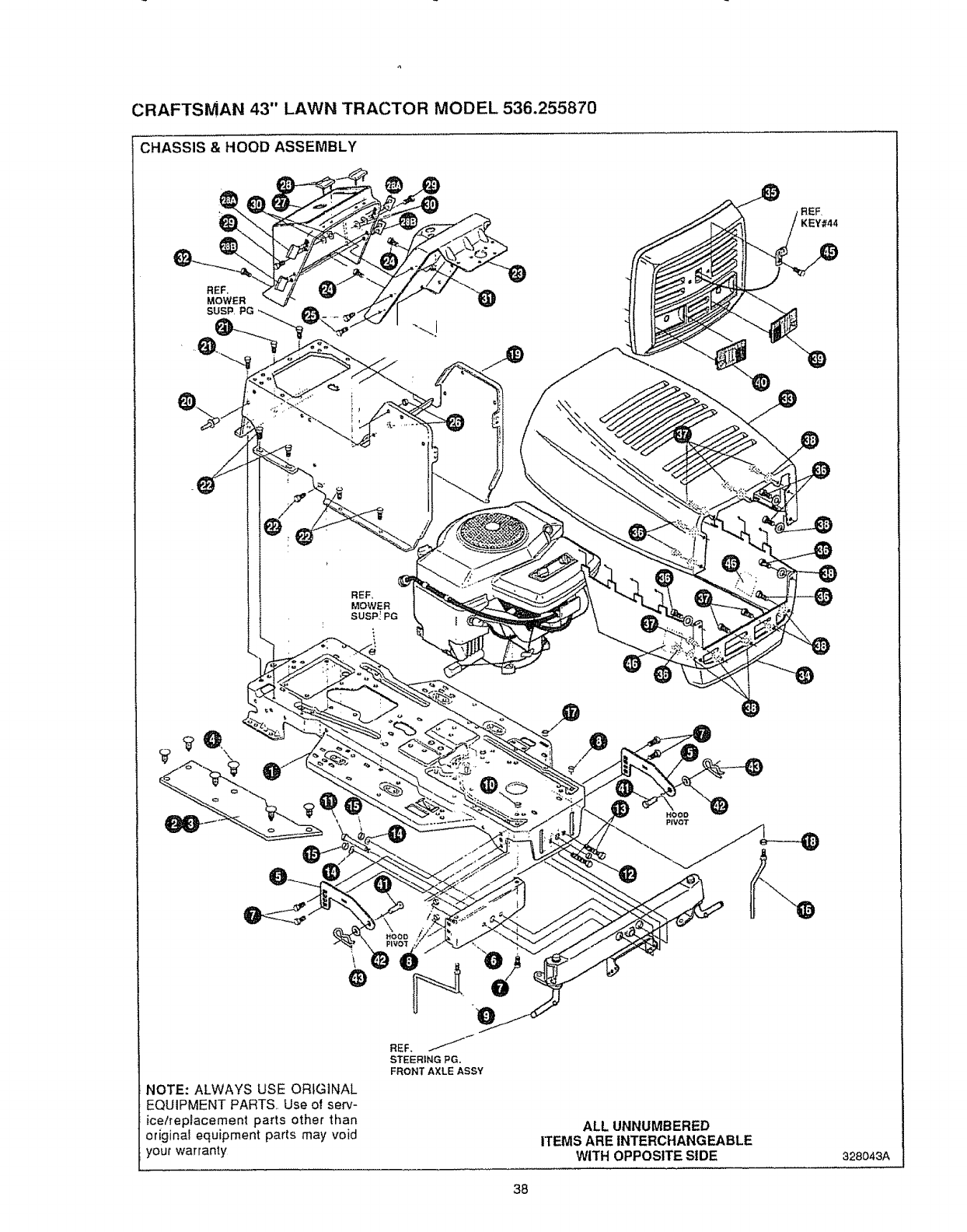
CRAFTSMAN 43" LAWN TRACTOR MODEL 536.255870
CHASSIS & HOOD ASSEMBLY
REE
KEY#44
REF,
MOWER
SUSP,! PG
HOOD
PIVOT
NOTE: ALWAYS USE ORIGINAL
EQUIPMENT PARTS,. Use of serv-
ice/replacement parts other than
original equipment parts may void
your warranty
REF,
STEERING PG,
FRONT AXLE ASSY
ALL UNNUMBERED
ITEMS ARE INTERCHANGEABLE
WITH OPPOSITE SIDE 328O43A
38
CRAFTSMAN 43" LAWN TRACTOR MODEL 536.255870
key# part# description
I 326580-829
2314799
3310006
4 309235
5 323068-853
6 313541-853
7 56030
8 55273
9 300440
10 .1498
1t 308207
12 309008
13 "122207
14 2483
15 "1499
16 300635
17 .124824
18 "271190
19 315120°829
20 46763
2I 35497
22 995346
23 324111-830
24 995346
25 995338
26 50352
27 319718
28 321810
28A 324491
28B 324492
29 318139
30 54569
31 ,1502
32 318304
33 328133
34 328131
35 328132
36 316043
37 316881
38 t501
39 314967
40 314968
4I 323044
42 996425
43 8260
44 328042
45 316042
46 301452
327865
FRAME,LF MAIN P920/F4360 SEARS
FOOTPAD,LH PEDAL LIFT
FOOTPAD,RH
FASTENER, RATCHET
BRACKET, GRILLE
BRACKET, FRONT AXLE
SCREW, 5/16-18X,75WDFLLK
NUT, 5!16-t8 HXWDFLLK
GUIDE, BELT, RIDER
NUT, 5/t6-18 REGHEXCTRLK
BOLT, 625X2 18 HHSH 112-13
NUT, 1t2-13 HEXJAM CTRLK
SCREW, 3/8-16X3 00 HHC
WASHER, 391DXI .25DX,,07 BELLVtL
NUT, 318-16 REGHXCTRLK
GUIDE,BELT SHORT 15" WHEEL
NUT. 5/16-18 HEXJAM
NUT, 3/8-16 HEXKEPS
CONSOLE, PEDAL LIFT
RIVET. POP ,,187DIAX 450LG ST
SCREW, 5/!8-t8X .50 WAHHTAP
SCREW, t/4-20X 50 WAHHTAP
DASH, STEEL
SCREW, 1/4-20X 50 WAHHTAP
SCREW, I/4-20X 63 HHWATAP
NUT, 114-20 WDFLLK TOPLOCK
DASH
BUMPER TOP
BUMPER-HOOD/DASH SIDE TOP
BUMPER-HOOD/DASH SIDE BOTTOM
SCREW, 114-20 PHPNHD
WASHER, FLAT 28tX .75X 090
NUT, 1/4-20 REGHXCTRLK
SCREW, tI4-20X 50 PHPNTAP
HOOD
SKIRT, HOOD
GRILLE
SCR #10X1 0 UNSL-HWH-HILO ZINC
SCR #t0X.75 UNSL-HWH-HILO ZINC
FLATWASHER #10
LENS LH, SEARS
LENS RH, SEARS
PIN, CLEVIS
FLATWASHER
PIN, HAIR
LANYARD,HOOD 18.00 LG LF
SCR #10X 62 UNSL-HWH-HILO ZINC
FOIL, HEAT REFLECTOR
OWNER'S MANUAL (NOT ILLUSTRATED)
" STANDARD HARDWARE ITEMS.
qty,
1
1
1
12
2
1
5
5
1
t
1
1
2
2
2
1
1
1
1
3
2
9
1
2
4
4
1
2
4
2
2
4
2
2
1
1
I
8
6
14
t
I
2
2
14
1
1
2
1
39
!
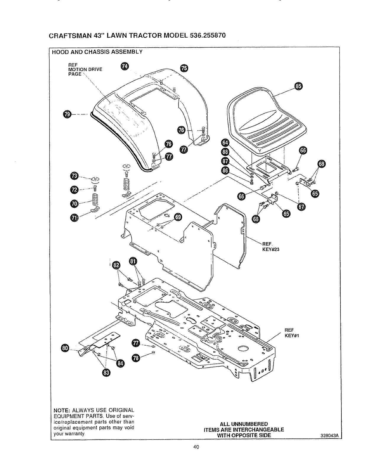
CRAFTSMAN43" LAWN TRACTOR MODEL536.255870
HOOD AND CHASSIS ASSEMBLY
REF _)
MOTION DRIVE
PAGE ",..
KEY#23
!
\
\
o
REF
KEY#t
NOTE: ALWAYS USE ORIGINAL
EQUIPMENT PARTS, Use of serv-
ice/replacement parts other than
original equipment parts may void
your warranty.
ALL UNNUMBERED
ITEMS ARE INTERCHANGEABLE
WITH OPPOSITE SIDE 328043A
4O
CRAFTSMAN 43" LAWN TRACTOR MODEL 536.255870
key# part# description
64 58367-853
65 310660-853
66 20507
67 ,I498
68 48901
69 .1498
70 57_53
71 1341
72 44811
73 569O7
74 308654-829
75 995346
76 *122017
77 446363
78 "1498
79 55021
80 327061-829
8I 48146
82 180079
83 120393
84 1498
85 321863
86 122007
87 120638
88 120393
PLATE, SEAT
BRACKET, P-5 SEAT SUPPORT
BOLT, 437X t56 HHSH 5/t6-18
NUT, 5/16-18 REGHEXCTRLK
SCREW, 5116-18X 63 HHC
NUT, 5/16-18 REGHEXCTRLK
SPRING,SEAT 2 63LG1 49OD
CLAMP,SPRING 1 t7"ID
SCREW, 114-20X ,75 HXWATAP
COVER,SEAT SPRING 1 51DX1 0LG
FENDER
SCREW. !/4-20X ,50 WAHHTAP
SCREW, 5/I6-t8X1,00 HHC
WASHER. FLAT .375X .88X 082
NUT. 5116-18 REGHEXCTRLK
TRIM,STRIP,BLACK--SMALL.W/ADH
HITCH. SEARS
SCR, 3/8-16 X t 000 HXWAHD TAP
SCR 5/t6q8 X 63 HHC
WASHER FLAT 344 X .69 X 065
NUT, 5/16-18 REGHEXCTRLK
SEAT. MV540 CRAFTSMAN
SCREW, 5/16q8 X ,75 HHC
WASHER. HVSPTLK 328 X .60 X 09
WASHER. FLAT 344 X 69 X 065
"STANDARD HARDWARE ITEMS°
qty
1
1
2
2
4
4
2
2
2
2
1
4
2
4
2
75"
t
2
2
2
2
1
4
4
4
4I

CRAFTSMAN 43" LAWN TRACTOR MODEL 536.2558"/0
MOWER SUSPENSION ASSEMBLY
NOTE: ALWAYS USE ORIGINAL
EQUIPMENT PARTS, Use of serv-
ice/replacement parts other than
original equipment parts may void
your warranty
ALL UNNUMBERED
ITEMS ARE INTERCHANGEABLE
WITH OPPOSITE SIDE
42
322997F
CRAFTSMAN 43" LAWN TRACTOR MODEL 536.255870
key'# part# description
1 320075-853
2.180079
3 120393
4 .1498
5 317089
6 50148
7 8260
8 318341
9 35498
10 324032
1! 48306
t2 316648
13 324045
14 315194
14A 1288
t5 .t502
t6 300698-853
17 . 180020
18 °1502
!9 324055
20 120613
21 35498
22 57444
23 322835-853
24 300169-853
25 .180079
26 58247
27 "1498
28 417098
29 8260
30 322821
3l 12O394
32 36368
33 996416
34 120377
35 322467
36 58248-853
37 126211
38 "t498
39 314962_853
40 314488
41 323751
42 126211
43 44108
44 315342
45 314829
46 .t499
47 314489
48 314792
49 121222
50 321385
51 274517
52 36368
53 315341
54 44811
55 324038
56 -1502
57 314969
58 314837
59 321837
60 180077
61 t498
BRACKET.CLUT-ENGAGELEVERBLK
SCREW, 5/16-!8X! O0 HHC
WASHER- FLAT .344X .69X 065
NUT, 5f16-18 REGHEXCTRLK
ASSY,CLUTCH LEVER
BEARING.FL 5031DX 628OD
PIN, HAIR 09t D1AXl.56LG
BRACKET.SWITCH ENGAGE
SCREW. 51t6-18X 75 WAHHTAP
CABLE KEEPER
PULLEY. POWDER METAL
SPRING 1288 LONG
BOLT..375X 565 HHSH 1/4-20
WASHER, FLAT 1 38 X 51 X 043 Z/YZ
BRACKET RETAINER
NUT, 1/4-20 REGHEXCTRLK
BRACKET. FRAME CABLE
SCREW, t/4-20X 75 HHC
NUT, 1/4-20 REGHEXCTRLK
ASSY.CABLE, BLADE ENGAGE
NUT, 1/4-28 HJAM
SCREW, 5/16-18X 75 WAHHTAP
TIE, CABLE BLACK
LIFT ASSY.LH P-LIFT J BLACK
ASSY LINK RIGHT SIDE
SCREW, 5/16-18X1 00 HHC
ADJUSTING NUT
NUT, 5116-18 REGHEXCTRLK
WASHER, FLAT 531Xl.06X 095
PIN, HAIR 091 DIAXI 66LG
ROD, ADJUSTING "'J" P-LIFT
WASHER, FLAT 406 X 81 X .065
PIN, HAIR 072 DtA X t t3 LG
WASHER FLAT 391 X t 00X I25
NUT. 3t8-t6 REG HX
NUT, 3t8-16 REG HX NK LOC
BRKT,REAR,HANG_SUSP
BOLT, 5t16-18X 63 CARR
NUT. 5/16-18 REGHEXCTRLK
PEDAL ASSY, DECK HEIGHT BLK
PAD, LiFT PEDAL
BRACKET, LIFT ARM
BOLT, 5116-18X 63 CARR
NUT, 5!16-t8 HWDFLCTRLK
LATCH,PEDAL LIFT
BOLT, 56 X .t3 HHSH 3t8-t6
NUT, 318q 6 REGHXCTRLK
SPRING. LIFT LATCH
ROD, PIVOT
PiN, COTTER .090! 086X 75
ROD, MEMORY
WASHER. FLAT 406X 73X 063
PIN,HAIR 072DIAX ! 13LG
BRACKET,ME MORY
SCREW, 1/4-20X 75 HXWATAP
GUIDE, MEMORY ROD
NOT. 114-20 REGHEXCTRLK
CAP, MEMORY ROD 381D X 75
SPRING. MEMORY
KNOB, MATTE BLACK
SCREW. 5f16-t8 X .75 HHC
NUT. 51t6-18 REGHEXCTRLK
. STANDARD HARDWARE ITEMS,
qty
1
2
2
2
1
1
1
t
1
1
1
1
1
1
1
t
1
2
2
1
1
1
1
l
I
1
1
1
2
2
1
!
1
1
t
1
2
4
4
1
1
1
4
4
I
1
1
1
1
2
1
3
t
2
4
1
4
1
1
1
1
1
!
43 !
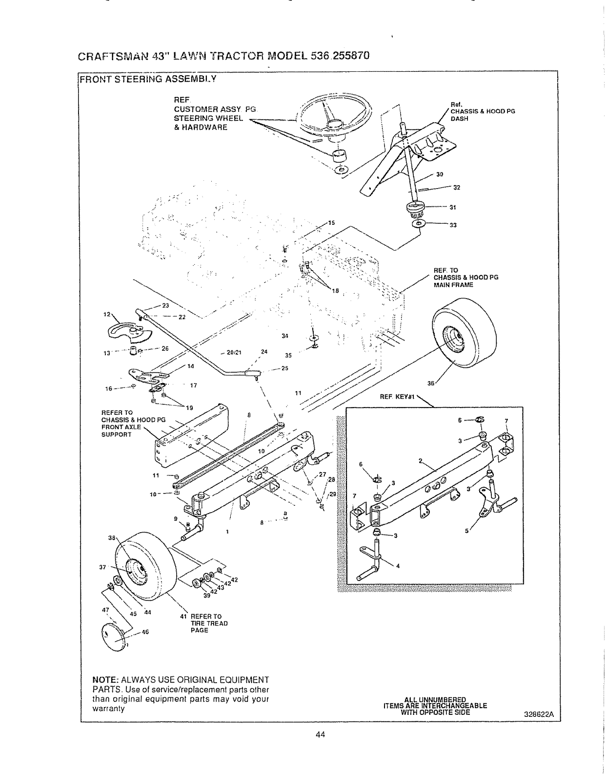
CRAFTS_IAN 43" LAWN TRACTOR _2,ODEL 536.255870
FRONT STEERING ASSEMBLY
REF,
CUSTOMER ASSY FG
STEERING WHEEL
& HARDWARE
14
t6 .......... _ ' 17
1
19
REFER TO
CHASSIS & HOOD PG
FRONT AXLE
SUPPORT
REF, TO
CHASSIS & HOOD PG
MAIN FRAME
& HOOD PG
,t242
39
'\\
41 REFER TO
TIRE TREAD
PAGE
NOTE: ALWAYS USE ORIGINAL EQUIPMENT
PARTS. Use of service/replacement parts other
than original equipment parts may void your
warranty
ALL UNNUMBERED
ITEMS ARE INTERCHANGEABLE
WITH OPPOSITE SIDE 328622A
44
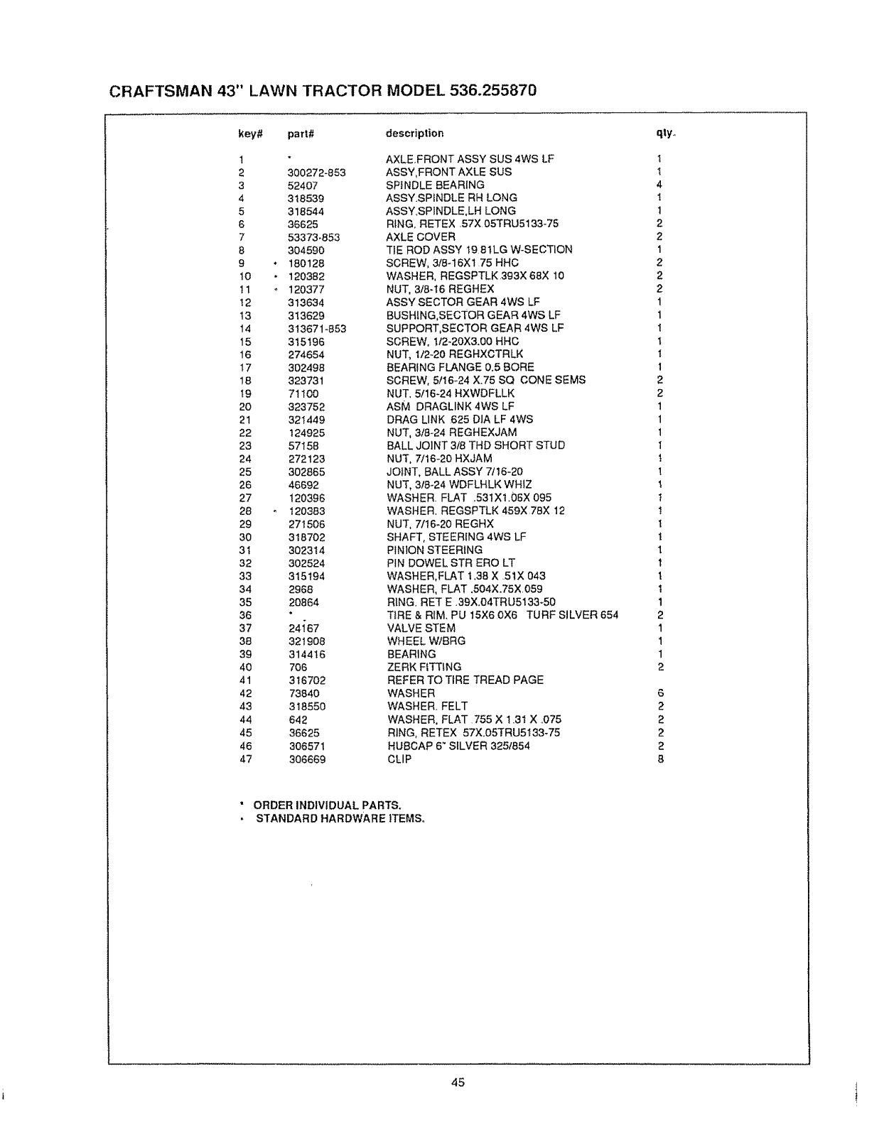
CRAFTSMAN 43" LAWN TRACTOR MODEL 536.255870
key# part# description
1
2 300272-853
3 52407
4 318539
5318544
6 36625
7 53373-853
8 304590
9 • 180128
t0 - 120382
11 . 120377
t2 313634
t3 313629
14 313671-853
t5 315196
16 274654
17 302498
18 323731
t9 71100
20 323752
21 321449
22 124925
23 57158
24 272123
25 302865
26 46692
27 120396
28 120383
29 271506
30 318702
3I 302314
32 302524
33 315194
34 2968
35 20864
36
37 24{67
38 321908
39 314416
40 706
41 316702
42 73840
43 318550
44 642
45 36625
46 306571
47 306669
AXLE.FRONT ASSY SUS 4WS LF
ASSY,FRONT AXLE SUS
SPINDLE BEARING
ASSY.SPfNDLE RH LONG
ASSY,SP1NDLE,LH LONG
RING, RETEX 57X 05TRU5133-75
AXLE COVER
TIE ROD ASSY 19 81LG W-SECTION
SCREW, 3/8-16X1 75 HHC
WASHER, REGSPTLK 393X 68X 10
NUT, 3/8q6 REGHEX
ASSY SECTOR GEAR 4WS LF
BUSHING,SECTOR GEAR 4WS LF
SUPPORT,SECTOR GEAR 4WS LF
SCREW, t/2-20X3.00 HHC
NUT, 1/2_20 REGHXCTRLK
BEARING FLANGE 0.5 BORE
SCREW, 5f16_24 X.75 SQ CONE SEMS
NUT, 5/16_24 HXWDFLLK
ASM DRAGLINK 4WS LF
DRAG LINK 625 DIA LF 4WS
NUT, 3/8-24 REGHEXJAM
BALL JOINT 3/8 THD SHORT STUD
NUT, 7/t6_20 HXJAM
JOINT, BALL ASSY 71t6-20
NUT, 3!6-24 WDFLHLK WHIZ
WASHER. FLAT ,531X1.06X 095
WASHER, REGSPTLK 459X 78X 12
NUT, 7/t6o20 REGHX
SHAFT, STEERING 4WS LF
PINION STEERING
PIN DOWEL STR ERO LT
WASHER,FLAT 1.38 X 5tX 043
WASHER, FLAT .504X.75X 059
RING. RET E .39X.04TRU5133_50
TiRE & RIM. PU 15X6 0X6 TURF SILVER 654
VALVE STEM
WH EEL W/BRG
BEARING
ZERK FITTING
REFER TO TIRE TREAD PAGE
WASHER
WASHER. FELT
WASHER, FLAT 755 X 13I X ..075
RING, RETEX 57X.05TRU5133-75
HUBCAP 6 _SILVER 3251854
CLIP
qlyo
I
I
4
!
1
2
2
1
2
2
2
1
1
1
1
1
1
2
2
1
1
1
I
t
!
!
t
t
t
t
1
t
1
t
1
2
1
1
1
2
6
2
2
2
2
8
" ORDER INDIVIDUAL PARTS.
. STANDARD HARDWARE ITEMS°
45
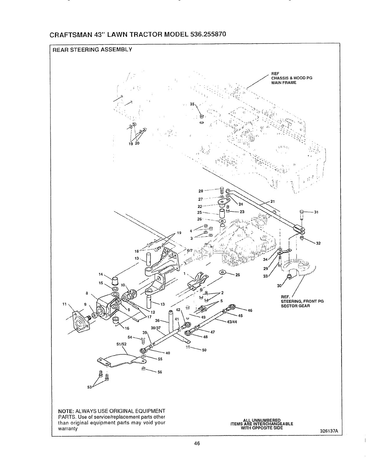
CRAFTSMAN 43" LAWN TRACTOR MODEL 536.255870
REAR STEERING ASSEMBLY
/
_ ,', i_ '_
!9 20
REF
CHASSIS & HOOD PG
_, _: .// MAINFRAME
NOTE: ALWAYS USE ORIGINAL EQUIPMENT
PARTS, Use of service/replacement parts other
than original equipment parts may void your
warranty
ALLUNNUMBERED
ITEMS AREINTERCHANGEABLE
WRH OPPOSITESIDE 326t37A
46

CRAFTSMAN 43" LAWN TRACTOR MODEL 536.255870
key# part# description
I 303222-853
2 180091
3120393
4 1498
5 35498
6 326135
7 314267
8 12465
9 12325
10 320531
11 12280-830
12 36311
13 12289
t4 324578
!5 21682
16 324578
17 456722
18 122017
19 120393
20 1498
21 324514
22 308719
23 12319
24 120394
25 304115
26 25177
27 45602
28 421051
29 302594
30 304116
31 304122
32 274654
33 324638
34 9963O7
35 412349
36 308720
37 323634
38 308447
39 308399
40 308384
4t 124925
42 304260
43 323635
44 3O8446
45 308399
46 308384
47 124925
48 3O4260
49 181646
50 412349
5! 304t20_853
52 304!21_853
53 39728
54 181639
85 120382
56 452349
BRKT X-AXLE MTG
0SCREW, 5tI6_18X2 50 HHC
WASHER, FLAT .344X .69X 065
0NUT, 5/16q8 REGHEXCTRLK
0SCREW, 5/16_18X .75 WAHHTAP
U-JOINT ASM 4WS LD LF
BRCKT,STRG PIVOT W/DRILL HOLES
BRACKET.STR PIVOT
BEARING
U_JOINT ASSEMBLY (LONG)
HUB ASSEMBLY GREY 86t
PIN. GROOVED .250 DIAX1 50LG
PiN, STEERING HINGE
BUSHING. SHOULDERED (OILITE
WASHER, FLAT .765Xt.25X.042 PL
BUSHING, SHOULDERED (OILITE
PIN, SPRING 250DIAX1 50LG HVPL
0SCREW, 5/16-t8X1 00 HHC
WASHER, FLA'r .344X .69X 065
0NUT. 5It6-18 REGHEXCTRLK
ROD ASM., DRAGLINK
PIVOT. STEERING
BOLT_ .562X 340 HHSH 318-24
WASHER. FLAT 406X 81X.065
SPACER, STEERING SHAFT
WASHER. FLAT 765X1 19X 048
WASHER, FLAT 333X 87X t19
0SCREW, 5/I6-24X1 00 HHC
ARM ROLLER SWING 4 W
CAM YOKE ROLLER
SHOULDER BOLT CAM ROLLER
0NUT. 1/2_20 REGHXCTRLK
SHOULD BOLT CAM FOLLOWER
WASHER, FLAT .391Xl L)0X 209
ONUT, 3/8-24 HXCTRLK
SHAFT, STEERING PIVOT
TIE ROD ASSY RH
ROD. TIE t/2"D X 8.00LG
0NUT, 3/8-24 LH THD REGHJAM
ROD,TIE END LH 3t8-24 EURO
0 NUT, 3/8o24 REGHEXJAM
ROD, TIE END RH
TIE ROD ASSY LH
ROD. TIE 112_DX 9.5LG
NUT, 3,'8-24 LH THD REGHJAM
ROD.TIE END LH 3/8-24 EURO
NUT. 3/8-24 REGHEXJAM
ROD, TIE END RH
0SCREW, 318_24Xt.75 HHC
0 NUT, 3t8-24 HXCTRLK
ARM RW STR ERO RH
ARM RW STR ERO LH
_)SCREW. 3t8-t6X 75WAHHTAP BK
0SCREW, 3/8-24Xl,25 HHC
WASHER, REGSPTLK 393X 68X 10
0 NUT, 3/8-24 HXCTRLK
qty
2
4
4
4
4
2
2
2
4
2
2
2
4
2
2
2
4
8
16
8
1
t
t
t
t
2
1
1
1
t
1
1
1
1
1
1
1
1
1
1
1
1
1
t
t
I
1
t
t
t
t
t
4
2
2
2
Indicates STANDARD HARDWARE ITEMS
47
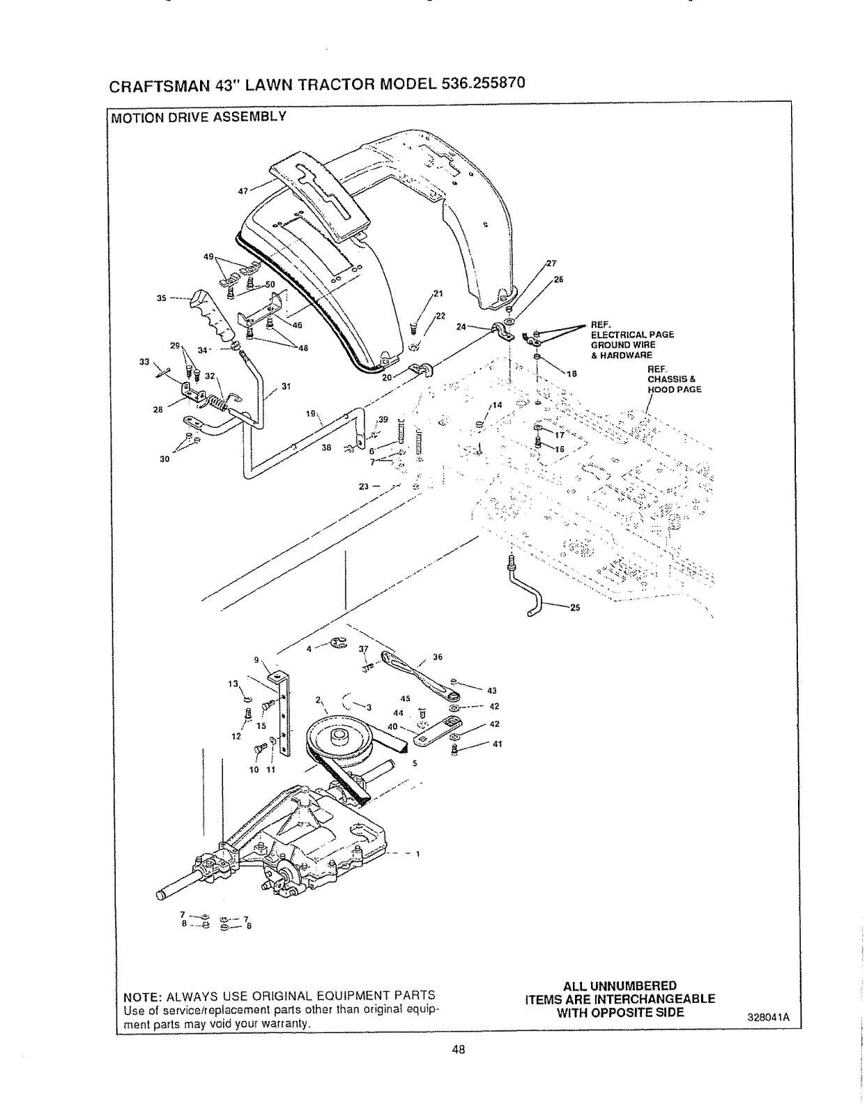
CRAFTSMAN 43" LAWN TRACTOR MODEL 536,.255870
MOTION DRIVE ASSEMBLY
49
33
NOTE: ALWAYS USE ORIGINAL EQUIPMENT PARTS
Use of service/replacement parts other than original equip-
ment parts may void your warranty,
48
ALL UNNUMBERED
ITEMS ARE INTERCHANGEABLE
WITH OPPOSITE SIDE 328041A
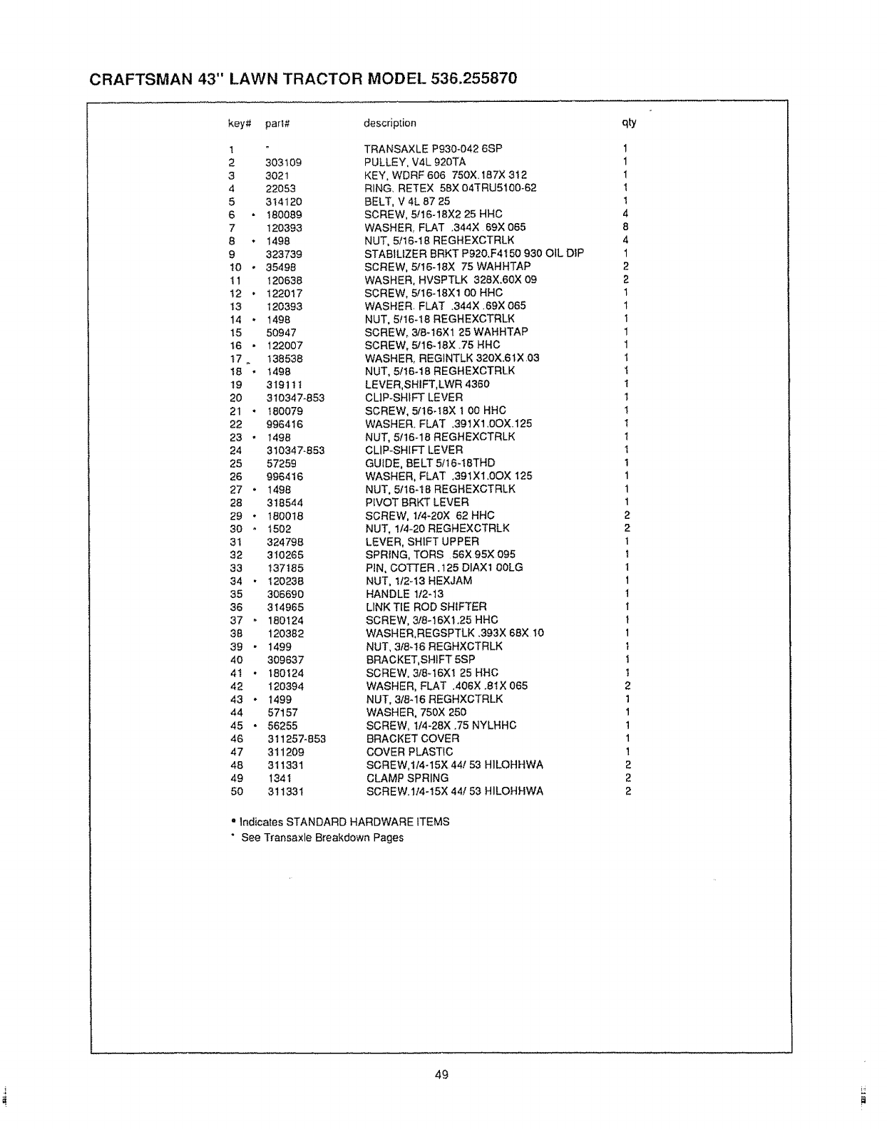
CRAFTSMAN 43" LAWN TRACTOR MODEL 536.255870
key# part# description
!
2303109
33o21
4 22053
5 314120
6 180089
7 120393
8 • 1498
9 323739
t0 • 35498
tl 120638
I2 • 122017
t3 120393
14 , 1498
15 50947
t6 • 122007
t7. 138538
I8 " t498
19 319111
20 310347-853
21 • 180079
22 996416
23 " I498
24 310347-853
25 57259
26 996416
27 •1498
28 318544
29 *180018
30 " t502
3I 324798
32 310265
33 137185
34 • 120238
35 306690
36 314965
37 " 180124
38 120382
39 • 1499
4O 309637
4t 180124
42 120394
43 •t499
44 57157
45 • 56255
46 311257-853
47 311209
48 311331
49 134I
5O 311331
TRANSAXLE P930-042 6SP
PULLEY, V4L 920TA
KEY, WDRF 606 750X t87X 3t2
RING, RETEX 58X 04TRU5100-62
BELT, V 4L 87 25
SCREW, 5t16-18X2 25 HHC
WASHER, FLAT .344X 69X 065
NUT, 5/16-!8 REGHEXCTRLK
STABILIZER BRKT Pg20.F4150 930 OIL DiP
SCREW, 5/t6-18X 75 WAHHTAP
WASHER, HVSPTLK 328X.60X 09
SCREW, 5,"16-18X1 O0 HHC
WASHER FLAT .344X 69X 065
NUT, 5t 16-18 REGHEXCTRLK
SCREW_ 318q6X1 25 WAHHTAP
SCREW, 5,,'16-18X _75 HHC
WASHER, REGINTLK 320X.61X 03
NUT, 5/t6-18 REGHEXCTRLK
LEVER,SHIFT,LWR 4360
CUP-SHIFT LEVER
SCREW, 5/16o18X t 00 HHC
WASHER. FLAT .39tX1.0OX 125
NUT, 51t6-18 REGHEXCTRLK
CLIP-SHIFT LEVER
GUIDE, BELT 5!16-ISTHD
WASHER, FLAT .391X1.0OX t25
NUT, 5116°18 REGHEXCTRLK
PIVOT BRKT LEVER
SCREW, 1/4-20X 62 HHC
NUT, 1/4-20 REGHEXCTRLK
LEVER, SHIFT UPPER
SPRING, TORS 56X 95X 095
PIN, COTTER .125 DIAXt 00LG
NUT, t/2-13 HEXJAM
HANDLE 1t2-13
LINK TIE ROD SHIFTER
SCREW, 3/8-16Xt.25 HHC
WASHER,REGSPTLK .393X 68Xt0
NUT, 3t8-t6 REGHXCTRLK
BRACKET,SHIFT 5SP
SCREW. 3/8q6X1 25 HHC
WASHER, FLAT ,406X .8t X 065
NUT, 3/8q 6 REGHXCTRLK
WASHER, 750X 250
SCREW, t/4-28X .75 NYLHHC
BRACKET COVER
COVER PLASTIC
SCREW,tI4-15X 44! 53 H1LOHHWA
CLAMP SPRING
SCREW,1t4-!5X 44/53 HILOHHWA
= Indicates STANDARD HARDWARE tTEMS
" See Transaxle Breakdown Pages
qty
1
1
I
t
!
4
8
4
1
2
2
1
1
1
1
1
t
1
1
t
t
!
t
I
I
1
1
1
2
2
1
1
1
1
1
1
t
1
t
I
t
2
t
1
t
1
!
2
2
2
49
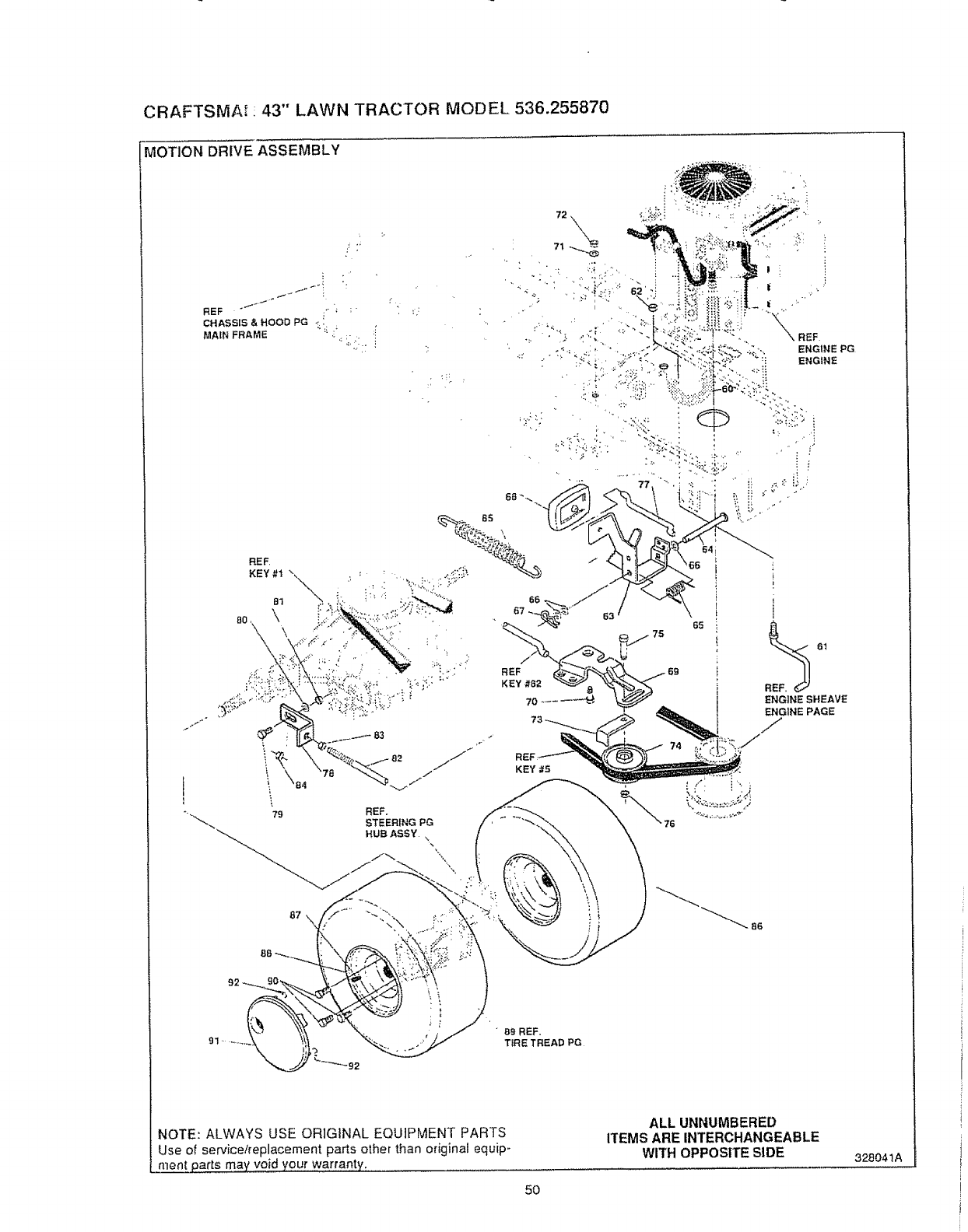
CRAFTSMA_ : 43 '' LAWN TRACTOR MODEL 536.255870
MOTION DRIVE ASSEMBLY
REF "_ '= '; ;'
CHASSIS & HOOD PG *. !
MAIN FRAME ";_ _
91 •89 REF,
TiRE TREAD PG
NOTE: ALWAYS USE ORIGINAL EQUIPMENT PARTS
Use o;_service!replacement parts other than original equip-
nlen! parts may' void your Warranty. .............
50
ALL UNNUMBERED
ITEMS ARE INTERCHANGEABLE
WITH OPPOSITE SIDE 328041A
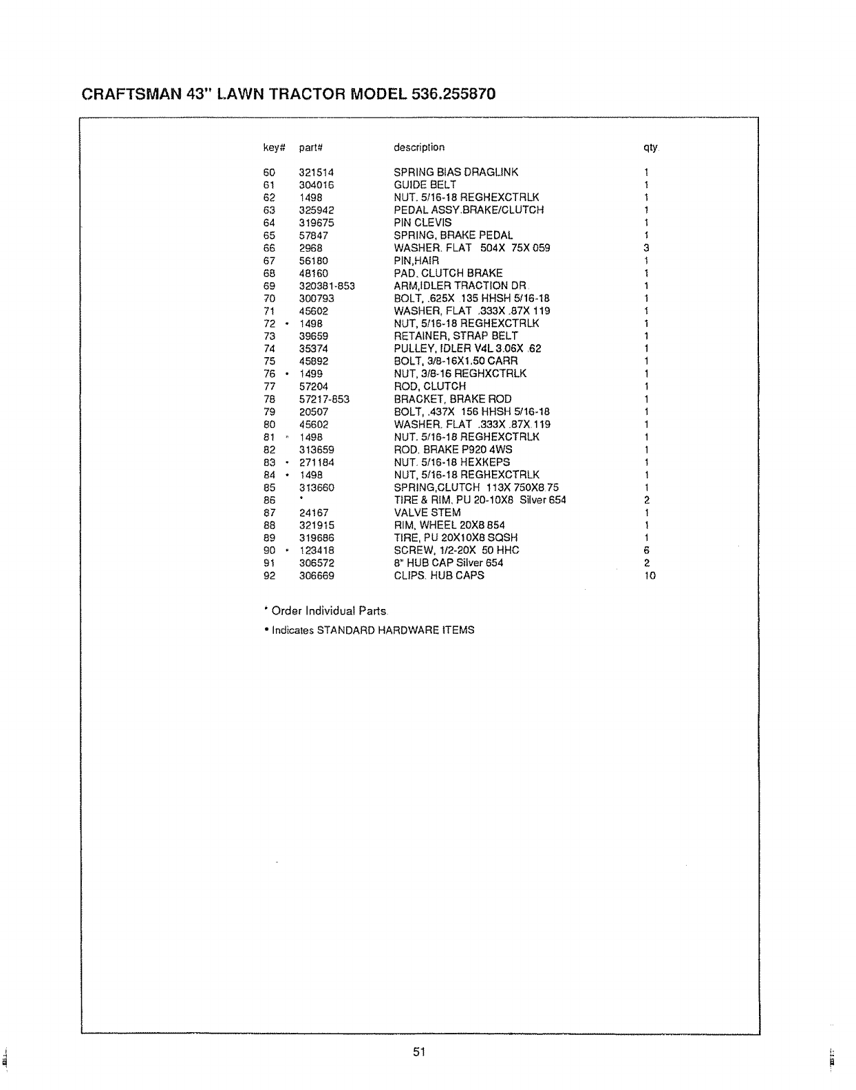
CRAFTSMAN 43" t.AWN TRACTOR MODEL 536,255870
key# part# description
60 321514
61 304016
62 1498
63 325942
64 319675
65 57847
66 2968
67 56180
68 48160
69 320381-853
70 300793
71 456O2
72 - 1498
73 39659
74 35374
75 45892
76 -t499
77 57204
78 572t7-853
79 20507
80 45602
81 1498
82 313659
83 • 271184
84 •1498
85 313660
86
87 24167
88 321915
89 319686
90 , 123418
91 306572
92 306669
SPRING BIAS DRAGUNK
GUIDE BELT
NUT. 5116-18 REGHEXCTRLK
PEDAL ASSY.BRAKE/CLUTCH
PIN CLEVIS
SPRING, BRAKE PEDAL
'WASHER. FLAT 504X 75X 059
PIN,HAtR
PAD, CLUTCH BRAKE
ARM,IDLER TRACTION DR
BOLT, .625X t35 HHSH 5116-t8
'WASHER, FLAT .333X .87X 119
NUT, 5!t6-t8 REGHEXCTRLK
RETAINER, STRAP BELT
PULLEY, IDLER V4L 3.06X 62
BOLT, 3/8-t6XI .50 CARR
NUT, 3/8q6 REGHXCTRLK
ROD, CLUTCH
BRACKET, BRAKE ROD
8OLT, .437X 155 HHSH 5/16q8
WASHER. FLAT .333X .87X. 119
NUT. 5/t6-18 REGHEXCTRLK
ROD. BRAKE P920 4WS
NUT. 5/t6-18 HEXKEPS
NUT, 5/16-t8 REGHEXCTRLK
SPRING,CLUTCH 113X 750X8 75
TIRE & RIM, PU 20-10X8 Silver 654
VALVE STEM
RIM, WHEEL 20X8 854
TIRE, PU 20XtOX8 SQSH
SCREW, !12-20X 50 HHC
8" HUB CAP Silver 654
CLIPS. RUB CAPS
'Order Individual Parts
• Indicates STANDARD HARDWARE 1TEMS
qty
!
t
t
!
t
t
3
t
t
t
1
!
I
t
t
1
1
1
1
1
1
1
1
1
1
1
2
1
1
1
6
2
lO
51 _:
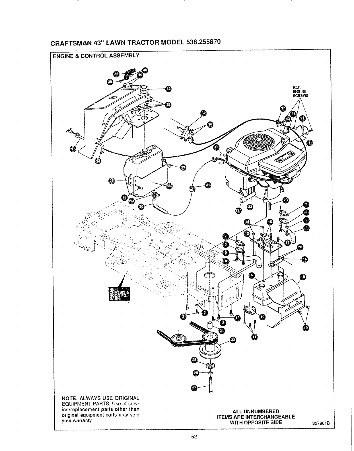
CRAFTSMAN 43" LAWN TRACTOR MODEL 536.255870
ENGINE & CONTROL ASSEMBLY
NOTE: ALWAYS USE ORIGINAL
EQUIPMENT PARTS, Use of serv-
ice/replacement parts other than
originat equipment parts may void
your warranty,
52
ALL UNNUMBERED
ITEMS ARE INTERCHANGEABLE
WITH OPPOSITE SIDE 327961B
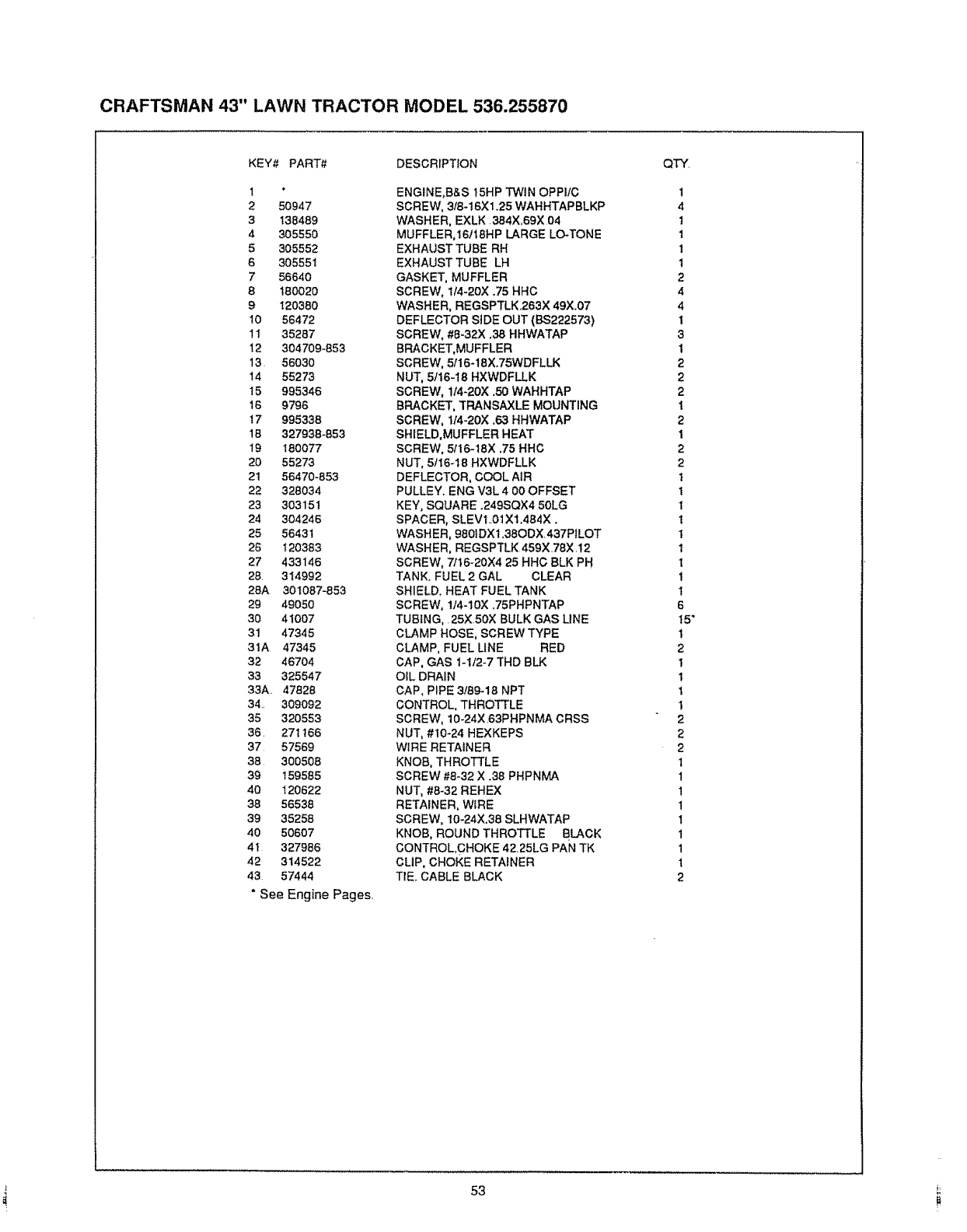
CRAFTSMAN 43" LAWN TRACTOR MODEL 536.255870
KEY# PART# DESCRIPTION
1*
2 50947
3138489
4305550
5 305552
6 305551
756640
8 t80020
9 120380
10 56472
11 35287
12 304709-853
13 56030
14 55273
15 995346
16 9796
t7 995338
18 327938-653
19 180077
20 55273
21 56470-853
22 328034
23 303151
24 304246
25 56431
26 120383
27 433146
28. 314992
28A 301087-853
29 49050
30 41007
31 47345
31A 47345
32 46704
33 325547
33A. 47828
34 309092
35 320553
36. 271166
37 57569
38 300508
39 159585
40 120622
38 56538
39 35256
40 50607
4t 327986
42 314522
43 57444
"See Engine Pages.
ENGINE,B&S 15HP TWIN OPP!tC
SCREW, 318-16X1.25 WAHHTAPBLKP
WASHER, EXLK 384X,69X 04
MUFFLER,16118HP LARGE LC-TONE
EXHAUST TUBE RH
EXHAUST TUBE LH
GASKET, MUFFLER
SCREW, 114-20X .75 HHC
WASHER, REGSPTLK.263X 49X.07
DEFLECTOR S] DE OUT (BS222573)
SCREW, #8-32X .38 HHWATAP
BRACKET, MUFFLER
SCREW, 5I! 6-18X.75WDFLLK
NUT, 5/16-18 HXWDFLLK
SCREW, 1/4-20X .50 WAHHTAP
BRACKET, TRANSAXLE MOUNTING
SCREW, 114-20X .63 HHWATAP
SHIELD,MUFFLER HEAT
SCREW, 5116-18X .75 HHC
NUT, 5/I 6-18 HXWDFLLK
DEFLECTOR, COOL AIR
PULLEY. ENG V3L 4 00 OFFSET
KEY, SQUARE .249SQX4 50LG
SPACER, SLEVt..01X1,484X ,
WASHER, 980IDX1.38ODX.437P_LOT
WASHER, REGSPTLK 459X78X 12
SCREW, 7116-20X4 25 HHC BLK PH
TANK. FUEL 2 GAL CLEAR
SHIELD, HEAT FUEL TANK
SCREW, 1/4-10X .75PHPNTAP
TUBING,. 25XSOX BULK GAS LINE
CLAMP HOSE, SCREW TYPE
CLAMP, FUEL LINE RED
CAP, GAS 1-1/2-7 THD BLK
OIL DRAIN
CAP, PIPE 3/89_18 NPT
CONTROL, THROTTLE
SCREW, 10-24X.63PHPNMA CRSS
NUT, #10-24 HEXKEPS
WIRE RETAINER
KNOB, THROTTLE
SCREW #8-32 X .38 PHPNMA
NUT, #8-32 REHEX
RETAINER, WIRE
SCREW, I0-24X.38 SLHWATAP
KNOB, ROUND THROTTLE BLACK
CONTROL CHOKE 4225LG PAN TK
CLIP, CHOKE RETAINER
TIE. CABLE BLACK
QTY
1
4
1
1
1
1
2
4
4
1
3
1
2
2
2
I
2
1
2
2
1
I
I
I
I
I
I
t
I
6
t5"
t
2
I
I
t
1
2
2
2
t
1
1
1
1
1
1
1
2
53
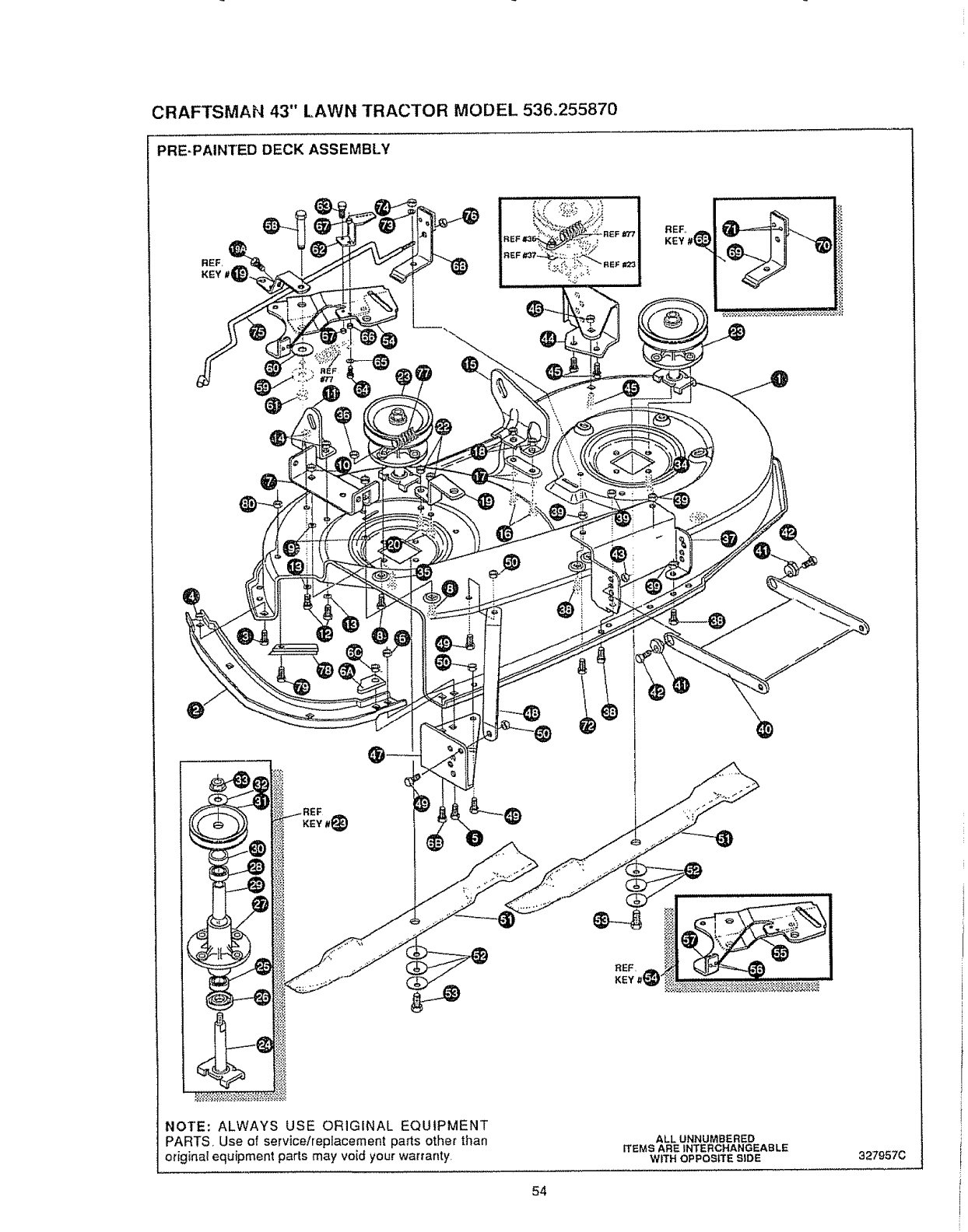
CRAFTSMAN 43" LAWN TRACTOR MODEL 536.255870
PRE-PAINTED DECK ASSEMBLY
REF,
KEY
NOTE: ALWAYS USE ORIGINAL EQUIPMENT
PARTS Use of service/replacement parts other than
original equipment parts may void your warranty.
ALL UNNUMBERED
ITEMS ARE INTERCHANGEABLE
WITH OPPOSITE SIDE 327957C
54

CRAFTSMAN 43" LAWN TRACTOR MODEL 536.255870
KEY# PART# DESCRIPTION
1327452
2 326480-853
3180075
41498
5 122007
61496
6A 327280-853
68 122027
6C 1498
7 317017
8180075
9120393
!0 I498
_I 313929
12 180077
t3120393
I4 t498
15 310667
16 180077
17 120393
18 t498
19 326893-853
19A 308231
20 180077
22 44108
23 55424-853
24 56425
25 49562
26 50616
27 55547
28 49562
29 50818
30 51449
3t 56390
32 313898
33 1282
34 50634
35 300345
36 1498
37 313778
38 180075
39 1498
40 58305
41 58247
42 122017
43 1498
44 304426
45 180075
46 1498
47 322464
48 314282
49 180075
SO t498
5t 325762
52 2483
53 47665
54 320576
55 322116
56 41601
57 306973
58 304420
59 996416
60 996307
61 45171
62 326249
63 t 80075
64 t 80083
65 448363
66 271184
67 1498
68 321828
69 304i t9-853
70 306973
71 135624
72 180075
73 120393
74 I498
75 314079
76 t502
77 35410
78 327570
79 126216
80 1498
MOWER DECKS. RIDER 43 _MULCHING
TOE GUARD
SCREW. 5/16-18X 63 HHC
NUT, 5/t 6-18 REGHEXCTRLK
SCREW. 5/!6q8X 75 HHC
NUT, 5/t6-18 REGHEXCTRLK
BRACKET, REFLECTOR STOP
SCREW, 5/16q 8X1.25
NUT, 5/t6.18 REGHEXCTRLK
BRACKET CHUTE MOUNT
SCREW, 5/16.18X ,63 HHC
WASHER,FLAT ,344x.6gx.065
NUT. 5/16-18 REGHEXCTRLK
LIFT BRACKET, REAR,RH
SCREW, 5/t6-18X .75 HHC
WASHER. FLAT .344X .6gx 065
NUT, 5fl 6-t 8REGHEXCTRLK
BRACKET,DECK UFTREAR LH
SCREW, 5!tTq8X .75 HHC GR5
WASHER, FLAT .344X .89X865
NUT, 5/I6-18 REGHEXCTRLK
BRACE IDLER
SCREW, 1/4-20Xl 25 HHWATAP
SCREW, 5/1648X .75 HHC
NUT, 5/16-18 HWDFLCTRLK
QUILL ASSY, 36/39/40/43
SHAFTISADDLE 36"
BRNG, BALL
DUST SHIELD
QUILL CAST{NG (1046)
BRNG. BALL
SPACER,3.797LGX,6691DXB8OD
SPACER,.438LGX 9320DX 672{D
PULLEY.2_36" QUILL V5L
SPECIAL WASHER
NUT, 7/16.20 WDFLLK
SCREW, 5/16-18X .88 WAHHTAP
SCREW, 5/t6-18Xl 38 WATAP
NUT, 5/16-t8 REGHEXCTRLK
BRACKET FRT.
SCREW, 5/t6-18X .63 HHC
NUT, 5/t6-18 REGHEXCTRLK
UNK BRACKET,DECK FR
ADJUSTING NUT
SCREW, 5/16-18X1.00 HHC
NUT, 5/t 6-18 REGHEXCTRLK
BRACKET,GAGE WHEEL L H,,
SCREW, 5!16q8X .63 HHC
NUT, 5/t6-18 REGHEXCTRLK
BRACKET.GAGE WHEEL R H FRNT
BRACKET,STABILIZER
SCREW, 5/16-18X ,63 HHC
NUT, 5/16-18 REGHEXCTRLK
BLADE, MULCHING 21,70
WASHER,.391DXt 25DX.07 BELLVJL
SCREW, 3/8-24Xl 25 NYLHHC GR5
iDLER ARM ASSY
iDLER ARM
RIVET
BRAKE PAD
SHOULDER BOLT
WASHER,FLAT 391XI OOX.125
WASHE R,FLAT .391X t.00X 209
NUT, 3/8-16 HWDFL WHE-LOCK
BRACKET. EXTENSION IDLER
SCREW 5/16-18X.63 HHCGR,5
SCREW, 5/16-18Xl 50 HHC GR 5
WASHER,FLAT
NUT 5/16-18 HEX KEPS
NUT
BLADE BRAKE ASSY
BRAKE ARM
BRAKE PAD
RIVET
SCREW, 5/16-18X,63
WASHER,FLAT .344X.69X.065
NUT, 5/16-t8 REGEHEXCTRLK
ROD,BRAKE
NUT,114.20 REGHEXCTRLK
SPRING
KICKER, MULCHER
BOLT 5/16-18X .75
NUT, 5/16-18 REGHE XCTRLK
QTYo
1
1
t
1
t
1
1
t
1
1
2
2
2
1
2
2
2
1
2
2
2
t
!
2
2
2
t
1
1
1
1
1
1
1
1
1
7
1
1
1
4
4
1
2
2
2
1
3
3
1
1
3
3
2
8
2
1
1
2
1
1
L
55 !
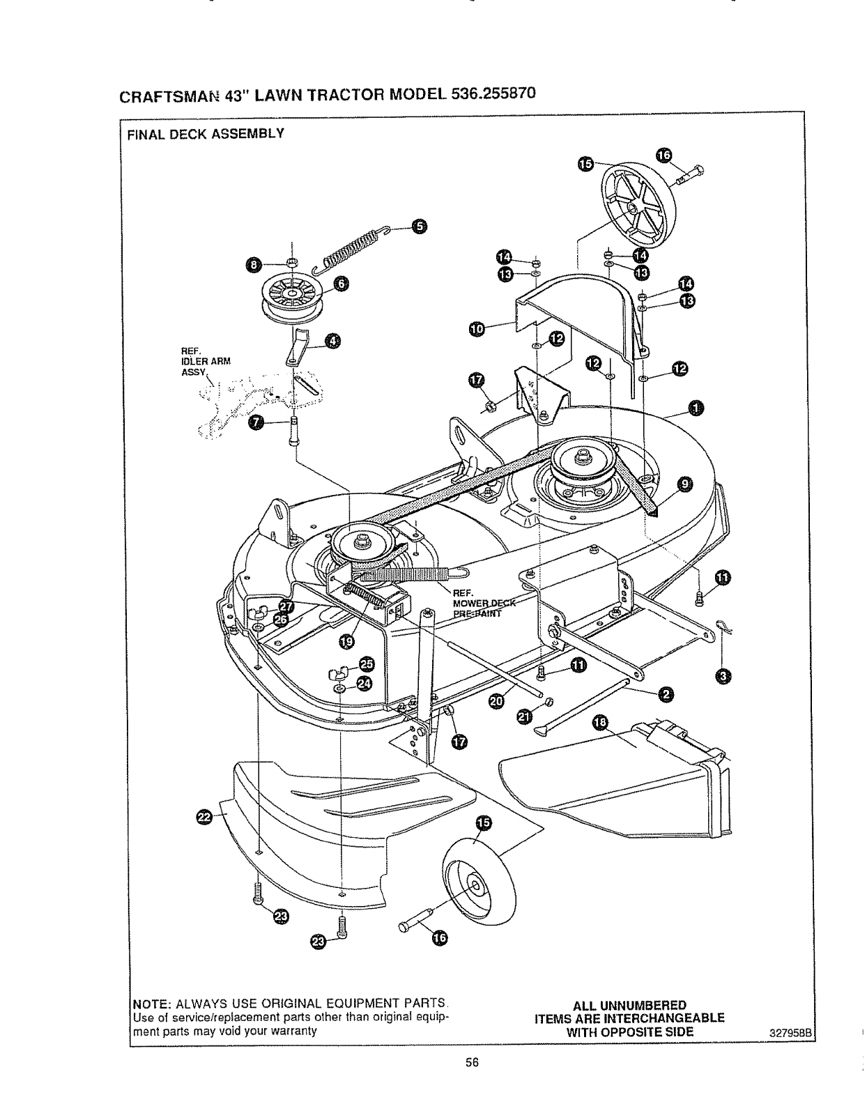
CRAFTSMAN 43" LAWN TRACTOR MODEL 536.255870
FINAL DECK ASSEMBLY
REF,
IDLER ARM
NOTE: ALWAYS USE ORIGINAL EQUIPMENT PARTS,
Use of service/replacement parts other than originat equip-
ment parts may void your warranty
ALL UNNUMBERED
ITEMS ARE INTERCHANGEABLE
WITH OPPOSITE SIDE 327958B
56
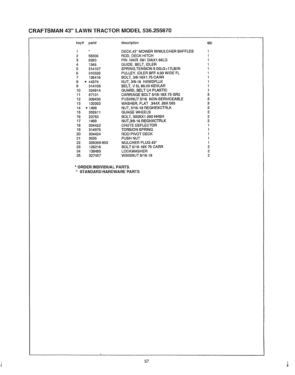
CRAFTSMAN 43" t.AWN TRACTOR MODEL 536.255870
key# pa_# descdption
1
2 56306
38260
4 1346
5314107
6310326
7 126416
8 = 44374
9 314108
10 324814
I1 57101
12 309436
13 120393
14 = 1498
15 302611
16 23763
17 1499
IB 304422
19 314975
20 304424
21 3535
22. 326369-653
23. 126216
24 138485
25. 327457
DECK,43 _ MOWER W/MULCHER BAFFLES
ROD, DECK HITCH
PIN. HAIR .09I DIAX1.66LG
GUIDE, BELT, IDLER
SPRING,TENSION 5.00LG+t 7LB/IN
PULLEY, IDLER BFF 4.00 WIDE FL
BOLT, 3/8-16X 1.75 CARR
NUT, 3/8-t6 HXWDFLLK
BELT, V 5L 86.00 KEVLAR
GUARD, BELT LH PLASTIC
CARRIAGE BOLT 5/16-18X 75 GR2
PUSHNUT 5!16 NON-SERVICEABLE
WASHER, FLAT .344X.69X065
NUT, 5f16.18 REGHEXCTRLK
GUAGE WHEELS
BOLT, 500XX1 390 HHSH
NUT,3/8-16 REGHXCTRLK
CHUTE DEFLECTOR
TORSION SPRING
ROD PIVOT DECK
PUSH NUT
MULCHER PLUG 43"
BOLT 5/16-t8X 75 CARR
LOCKWASHER
WlNGNUT 5116-18
qty,
1
1
1
I
1
1
1
t
I
1
3
3
3
3
2
2
2
t
1
1
1
I
2
2
2
* ORDER INDIVIDUAL PARTS°
°STANDARD HARDWARE PARTS
i.........
57
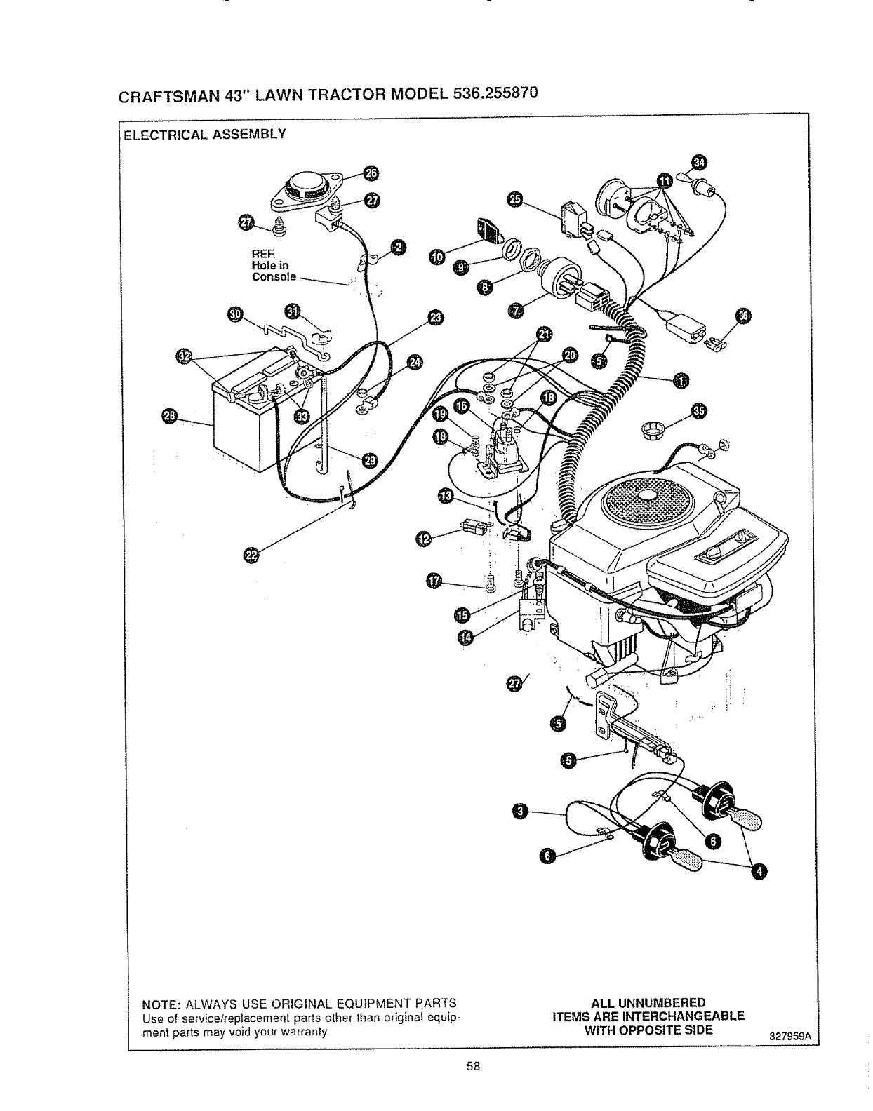
CRAFTSMAN 43" LAWN TRACTOR MODEL 536.255870
ELECTRICAL ASSEMBLY
NOTE: ALWAYS USE ORIGINAL EQUIPMENT PARTS
Use of service/replacement parts other than origina! equip_
ment parts may void your warranty
ALLUNNUMBERED
ITEMS AREINTERCHANGEABLE
WITH OPPOSITESIDE 327959A
58
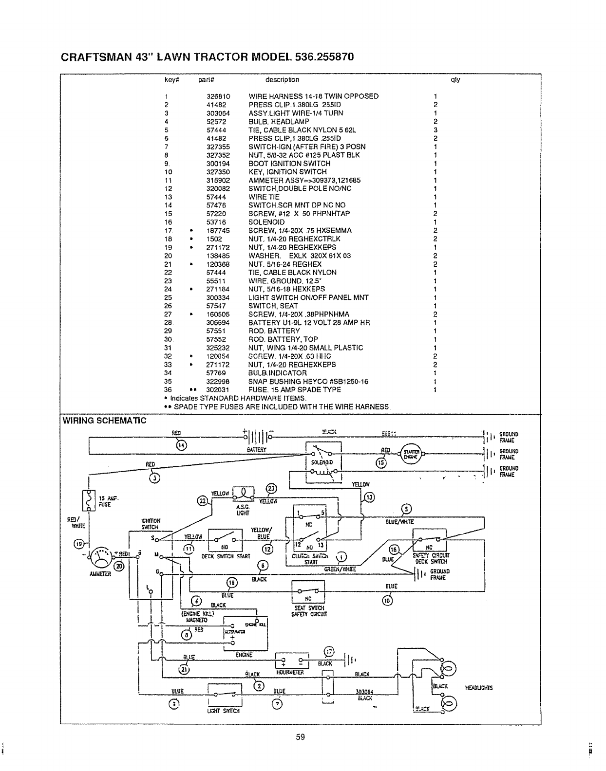
CRAFTSMAN 43" LAWN TRACTOR MODEL 536.255870
key#-, part# description qly
1326810
2 41482
3303064
4 52572
5 57444
6 41482
7327355
8 327352
9 300194
t0 327350
tt 315902
12 320082
13 57444
14 57476
15 57220
16 53716
17 = 187745
18 • 1502
19 * 271172
20 138485
21 • 120368
22 57444
23 55511
24 •271184
25 300334
26 57547
27 * 160505
28 306694
29 57551
30 57552
3t 325232
32 • 120854
33 • 271172
34 57769
35 322998
36 o_ 302031
WIRE HARNESS 14-t8 TWIN OPPOSED
PRESS CLIP.I 380LG 255ID
ASSY.LtGHT WIREd/4 TURN
BULB, HEADLAMP
TIE, CABLE BLACK NYLON 5 62L
PRESS CLIP,t .380LG .2551D
SWtTCH-IGN.(AFTER FIRE) 3POSN
NUT, 5/8-32 ACC #125 PLAST BLK
BOOT IGNITION SWITCH
KEY, IGNITION SWITCH
AMMETER ASSY_>309373,121685
SWITCH,DOUBLE POLE NO/NC
WIRE TIE
SWITCH.SCR MNT DP NC NO
SCREW, #12 X 50 PHPNHTAP
SOLENOID
SCREW, t14-20X .75 H×SEMMA
NUT. 114-20 REGHEXCTRLK
NUT, 1/4-20 REGHEXKEPS
WASHER. EXLK 320X 61X 03
NUT, 5/16-24 REGHEX
TIE, CABLE BLACK NYLON
WIRE, GROUND, 12,5"
NUT, 5tt6-I8 HEXKEPS
LIGHT SWITCH ON/OFF PANEL MNT
SWITCH, SEAT
SCREW, I14-20X .38PHPNHMA
BA'i-rERY ut-gL 12 VOLT 28 AMP HR
ROD, BATTERY
ROD. BATTERY, TOP
NUT, WING 1/4-20 SMALL PLASTIC
SCREW, 1/4-20X ,63 HHC
NUT, 1/4-20 REGHEXKEPS
BULB,INDICATOR
SNAP BUSHING HEYCO #SB1250-16
FUSE, 15 AMP SPADE TYPE
1
2
1
2
3
2
1
1
1
1
1
1
1
1
2
1
2
2
1
2
2
1
t
1
1
t
2
1
1
1
1
2
2
1
t
1
_' tndicates STANDARD HARDWARE ITEMS.
*_' SPADE TYPE FUSES ARE INCLUDED WiTH THE WIRE HARNESS
t
59
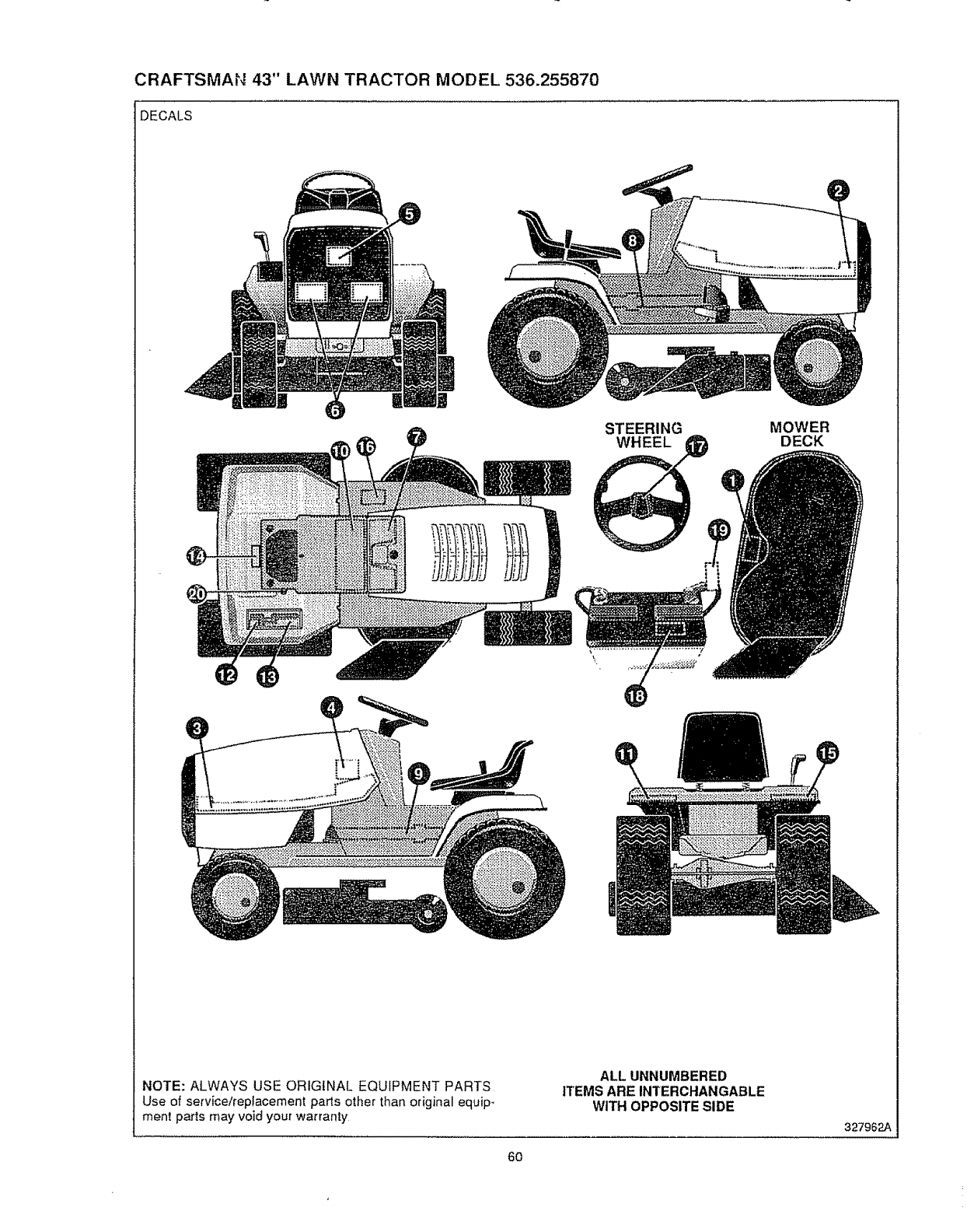
CRAFTSMAN 43" LAWN TRACTOR MODEL 536.255870
DECALS
STEERING
WHEEL MOWER
DECK
NOTE: ALWAYS USE ORIGINAL EQUIPMENT PARTS
Use of service#ep_acement parts other than original equip-
ment parts may void your warranty
ALL UNNUMBERED
ITEMS ARE INTERCHANGABLE
WITH OPPOSITE SIDE
327962A
60
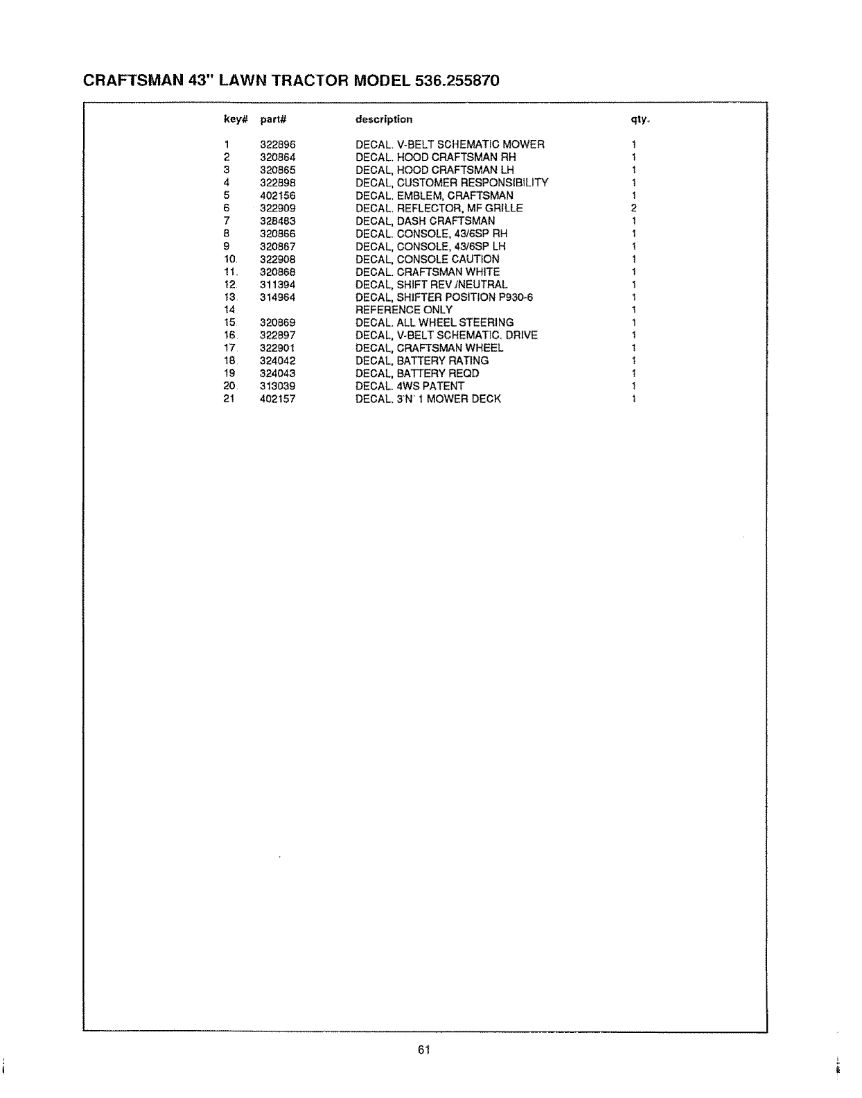
CRAFTSMAN 43" LAWN TRACTOR MODEL 536.255870
key'# part# description
1 322896
2 320864
3 320865
4322898
5402156
6322909
7328483
8 320866
9 320867
10. 322908
1t.. 320868
t2. 311394
t3 314964
I4
t5 320869
t6 322897
17 322901
18 324042
19 324043
20 313039
2! 402157
DECAL V-BELT SCHEMATIC MOWER
DECAL, HOOD CRAFTSMAN RH
DECAL, HOOD CRAFTSMAN LH
DECAL, CUSTOMER RESPONSIBILITY
DECAL. EMBLEM, CRAFTSMAN
DECAL. REFLECTOR, MF GRILLE
DECAL, DASH CRAFTSMAN
DECAL. CONSOLE, 4316SP RH
DECAL, CONSOLE, 4316SP LH
DECAL, CONSOLE CAUTION
DECAL. CRAFTSMAN WHITE
DECAL, SHIFT REVINEUTRAL
DECAL, SHIFTER POSITION P930-6
REFERENCE ONLY
DECAL. ALL WHEEL STEERING
DECAL, V-BELT SCHEMATIC, DRIVE
DECAL, CRAFTSMAN WHEEL
DECAL, BATTERY RATING
DECAL, BATFERY REQD
DECAL. 4WS PATENT
DECAL. 3N 1 MOWER DECK
qly,.
1
1
1
t
1
2
t
I
I
1
1
1
1
t
t
t
!
t
!
t
t
6t
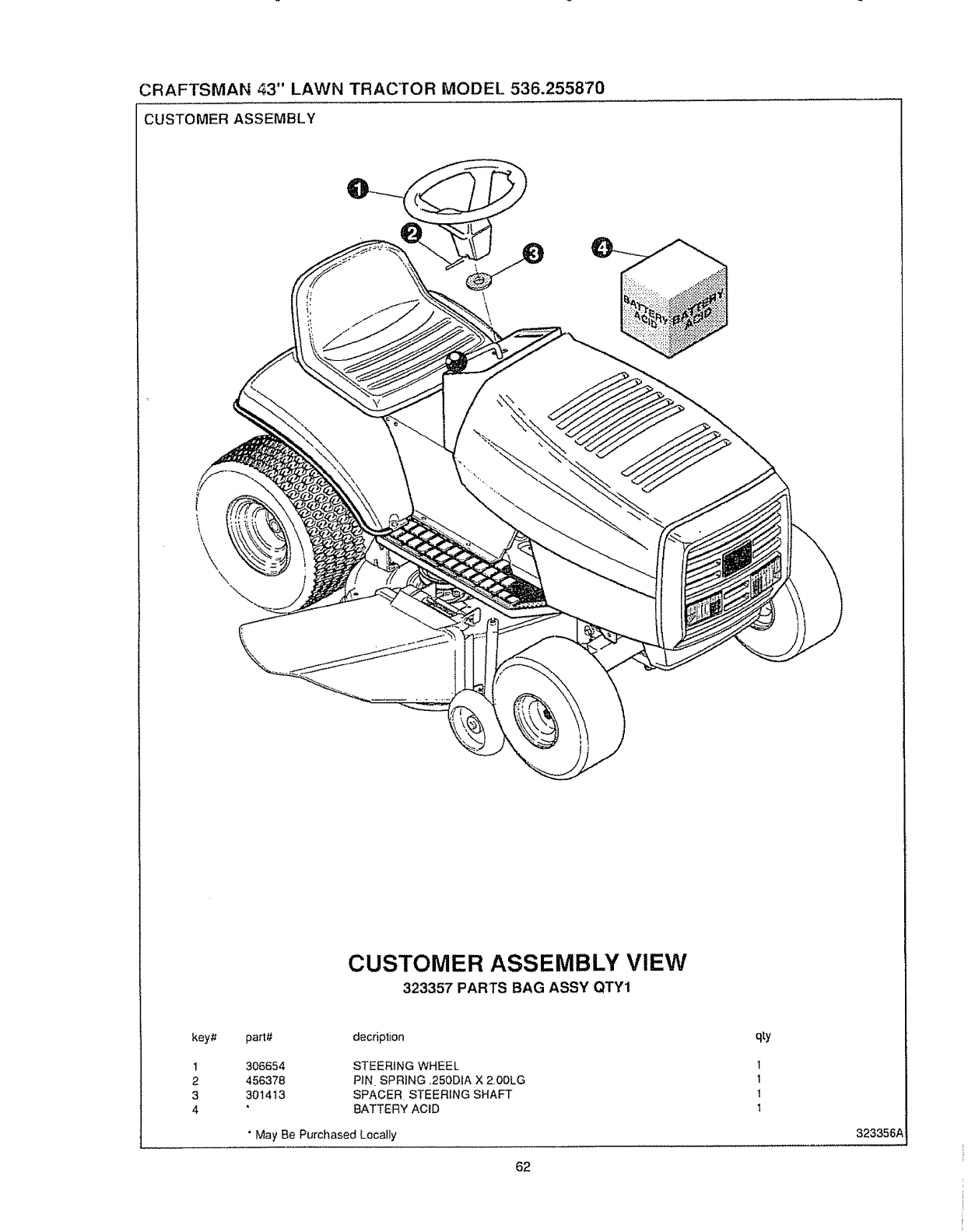
CRAFTSMAN 43" LAWN TRACTOR MODEL 536.255870
CUSTOMER ASSEMBLY
CUSTOMER ASSEMBLY VIEW
323357 PARTS BAG ASSY QTY1
key#
1
2
3
4
part# decdption
306654
456378
301413
STEERING WHEEL
PiN SPRING ,250DIA X 2,00LG
SPACER STEERING SHAFT
BATTERY ACiD
"May Be Purchased Locally
62
qty
1
t
1
t
323356_
.... i
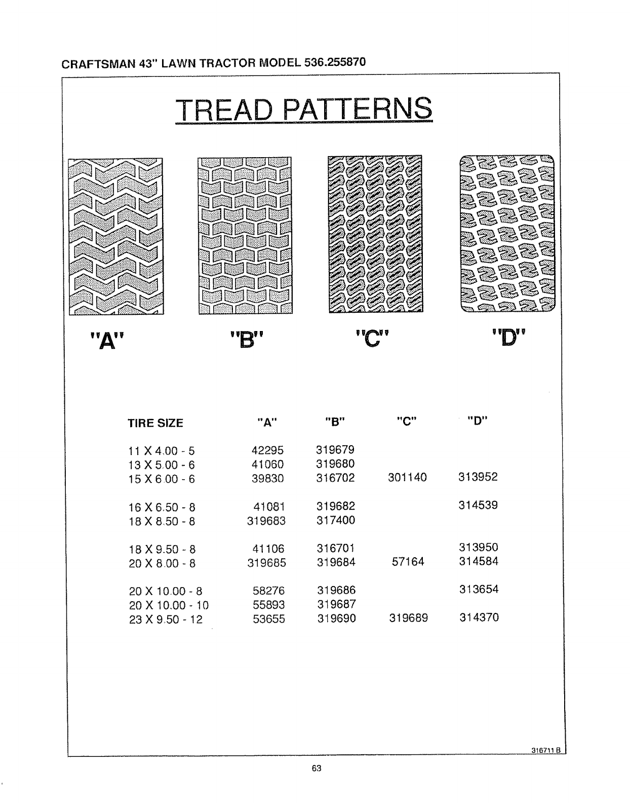
CRAFTSMAN 43" LAWN TRACTOR MODEL 536.255870
TREAD PATTERNS
w,A,v
TIRE SIZE "A" "B" "C" "D"
11 X 4,00 - 5
13 X5,00- 6
15 X 6 O0 - 6
16 X 6,50 - 8
18 X 8,50 - 8
18 X 9.50 - 8
20 X 8.00 - 8
42295 319679
41060 319680
39830 316702
41081 319682
319683 317400
41106 316701
319685 319684
20 X 10.,00-8 58276 319686
20 X 1000-10 55893 319687
23 X 9,50-!2 53655 319690
301140
57164
319689
313952
314539
313950
314584
313654
314370
63
316711 B
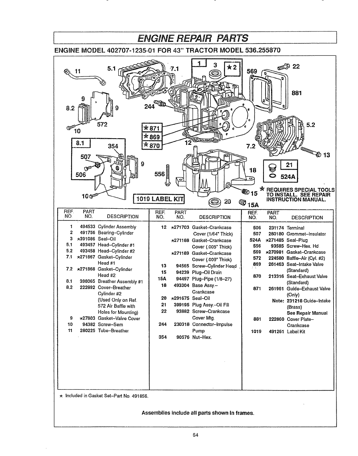
ENGINE REPAIR PARTS
ENGINE MODEL 402707-1235-01 FOR 43" TRACTOR MODEL 536.255870
s.1 3 22
9
9 556_
1019 LABEL ,,,
REF, PART
NO NO. DESCRIPTION
1 494533 Cylinder Assembly
2 491756 Bearing-Cylinder
3_391086 SeaF-Oi]
5.! 493457 Head-Cylinder #1
5.2 493458 Head-Cylinder #2
7,1 _271867 Gasket-Cylinder
Head #1
7.2 ;_271868 Gasket-Cylinder
Head #2
8_t 398085 Breather Assembly #1
8°2 222892 Cover-Breather
Cylinder #2
(Used Only on Ref,
572 Air Baffle with
Holes for Mounting)
9 _:27803 Gasket-Valve Cover
10 94382 Screw-Sem
11 280225 Tube-Breather
REE PART
NO. NO.
12 _271703
_271188
:_271189
13 94565
15 94239
15A 94497
18 493304
20 w291675
21 399195
22 93882
244 239318
354 90576
881
5.2
7.2
18I 524AI
"k REQUIRES SPECIAL TOOLS
TO INSTALL SEE REPAIR
{_20 _15A INSTRUCTION MANUAL,
REF. PART
DESCRIPTION
Gasket-Crankcase
Cover (1/64" Thick)
Gasket-Crankcase
Cover (4005" Thick)
Gasket-Crankcase
Cover (,.009" Thick)
Screw-Cylinder HeaFt
Plug-,Oii Drain
Plug-Pipe (t/827)
Base Assy.-
Crankcase
Seal-Oil
Plug Assy.--Oil Fill
Screw-Crankcase
Cover Mtg..
Connector--Impulse
Pump
Nut-Hexo
NO. NO. DESCRIPTION
506 231174 Terminal
507 280180 Grommet-Insulator
524A -_271485 Seal-Plug
556 93585 Screw-Hex_ Hd
569 _270981 Gasket.Crankcase
572 224580 Baffle-Air (CyL #2)
869 261453 Seat-Intake Valve
(Standard)
870 213316 Seat-Exhaust Valve
(Standard)
871 26'1961 Guide-Exhaust Valve
(Only)
Note: 231218 Guide-lntake
(Brass)
See Repair Manual
881 222860 Cover Plate-
Crankcase
1019 491261 Label Kit
Included in Gasket Set-Part No 491856,.
Assemblies include all parts shown In frames.
64
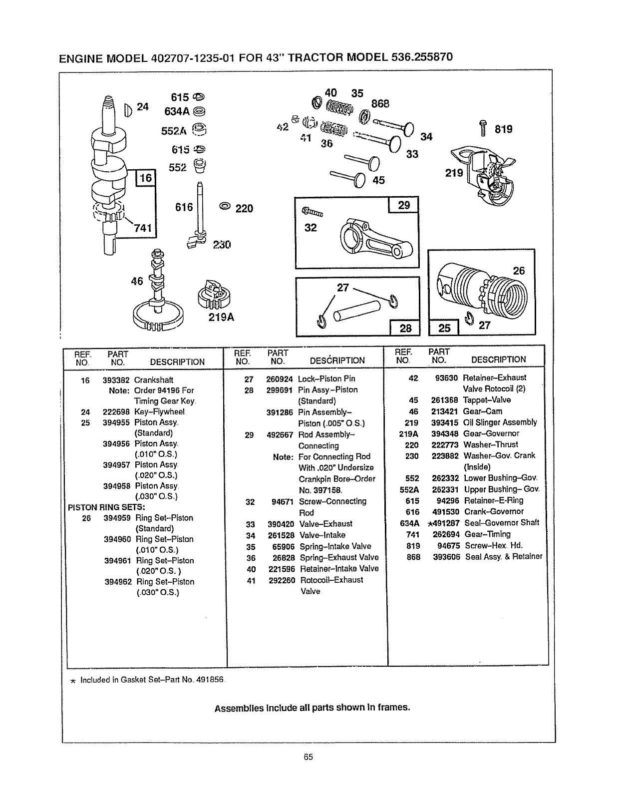
ENGINE MODEL 402707-1235-01 FOR 43" TRACTOR MODEL 536.255870
t*"
_[_ 615 q_
24 634A _)
552A _';
615
552
t_
616 H @ 220
230
219A
40 35
e 868
,,2_ _' I_, -_ @_ "_
"36 33
32
34 819
26
REE PART
NO. NO. DESCRIPTION
42 93630 Retainer-Exhaust
Valve Rotocoil (2)
45 261368 Tappet-Valve
46 213421 Gear-Cam
219 393415 Oil Slinger Assembly
219A 394348 Gear-Governor
220 222773 Washer-Thrust
230 223882 Washer-Gov,, Crank
(Inside)
552 262332 Lower Bushing--Gow
552A 262331 Upper Bushing- Govo
615 94296 Retainer-E-Ring
616 491530 Crank-Governor
634A -_491287 Seal-Governor Shaft
741 262694 Gear-Timing
819 94675 Screw-Hex Hd.,
868 393606 Sea[ Assy, & Retainer
REE PART REE PART
NQ NOo DESCRIPTION NO., NO. DES(_RIPTION
16 27 260924 Lock-PistonPin
28 299691 Pin Assy--Piston
(Standard)
391286 Pin Assembly-
393382 Crankshaft
Note: Order 94196 For
Timing Gear Key,
24 222698 Key-Flywheel
25 394955 Piston Assy,
(Standard)
394956 Piston Assy.
(_OlO"o,£,)
394957 Piston Assy
(,020" 03°)
394958 Piston Assy
(.030" O,S,)
PISTON RING SETS:
Piston (,005" OSo)
29 492667 Rod Assembly-
Connecting
Note: ForConnectingRod
With.020" Undersize
CrankpinBore-Order
No,,397158°
32 94671 Screw-Connecting
Rod
26 394959 Ring Set-Piston
(Standard)
394960 Ring Set-Piston
(.010" O,,S.)
394961 Ring Set-Piston
(.020"O,S,,)
394962 Ring Set-Piston
(,030" O,,S.)
33 390420 Valve-Exhaust
34 261528 Valve-intake
35 65906 Spring-Intake Valve
36 26828 Spring-Exhaust Valve
40 221596 Retainer-intake Valve
41 292260 RotocoiI-Exhaust
Valve
Included in Gasket Set-Part Nor 491856,
Assemblies include all parts shown In frames.
65
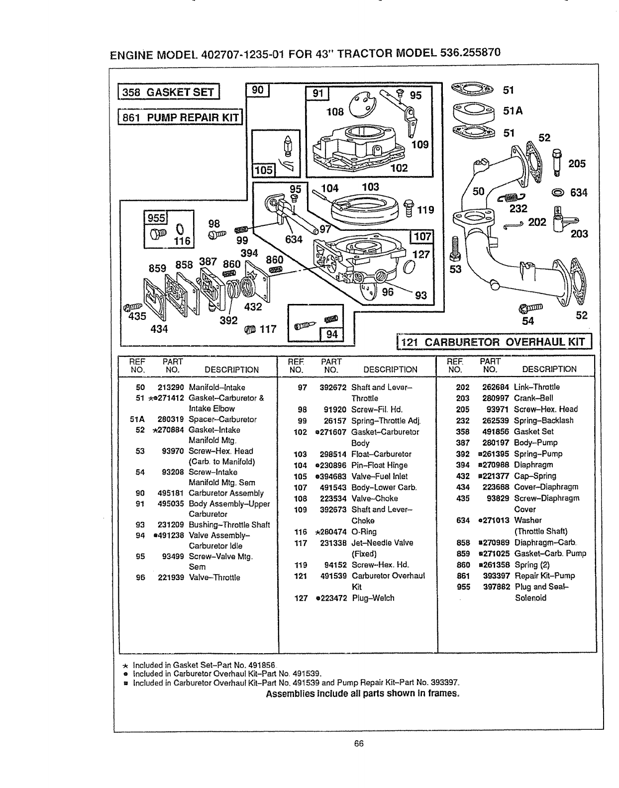
ENGINE MODE[. 402707-1235-01 FOR 43" TRACTOR MODEL 536.255870
358 GASKETSET !
[861 PUMP REPAIR KIT
19551.....I 98
859
392
434 _117
REF PART
NO, NO. DESCRIPTION
50 213290 Manifold-Intake
51 _=271412 Gasket--Carburetor&
Intake Elbow
51A 280319 Spacer-Carburetor
52 _270884 Gasket-Intake
Manifold Mtg.
53 93970 Screw-Hexo Head
(Carb to Manifold)
54 93208 Screw-Intake
Manifold Mtg, Sem
90 495181 Carburetor Assembly
91 495035 Body Assembly-Upper
Carburetor
93 231209 Bushing-Throttle Shaft
94 e491238 Valve Assembly-
Carbureter Idle
95 93499 Screw-Valve Mtg.
Sere
95 221939 Valve-Throttle
,08@
109
102
104 103
_119
51
51A
51 52
205
_634
I52
54
_'1_'! CARBURETOR OVERHAUL KIT
REF PART
NO. NO. DESCRIPTION REE PART
NO. NO. DESCRIPTION
202 262684 Link-Throttle
203 280997 Crank-Bell
205 93971 Screw-Hex,, Head
232 262539 Spring-Backlash
358 491856 Gasket Set
387 280197 Body-Pump
392 ==261395 Spring-Pump
394 =270988 Diaphragm
432 ,.221377 Cap-Spring
434 223688 Cover-Diaphragm
435 93829 Screw-Diaphragm
Cover
634 e271013 Washer
(Throttle Shaft)
858 "270989 Diaphragm-Carb,
859 =271025 Gasket-Carb Pump
860 =261358 Spring (2)
861 393397 Repair Kit-Pump
955 397882 Plug and Seal-
Solenoid
97 392672 Shaft and Lever-
Throttle
98 91920 Screw-Fi],, Hd,,
99 26157 Spring-Throttle Adj.
102 m271607 Gasket-Carburetor
Body
103 298514 Float-Carburetor
104 =230896 Pin-Roat Hinge
105 =394683 Valve-Fuel Inlet
107 491543 Body-Lower Carb,,
108 223534 Valve-Choke
109 392673 Shaft and Lever-
Choke
116 .280474 O-Ring
117 231338 Jet-Needle Valve
(Fixed)
119 94152 Screw-Hex_ Hd.
121 491539 Carburetor Overhaul
Kit
127 e223472 Plug-Welch
:k Included in Gasket Set-Part Ne. 491856
oincluded in Carburetor Overhaul Kit-Part Ne, 491539.
= Included in Carburetor Overhaul Kit-Part No. 491539 and Pump Repair Kit-Part No. 393397,,
Assemblies include all parts shown in frames,
66
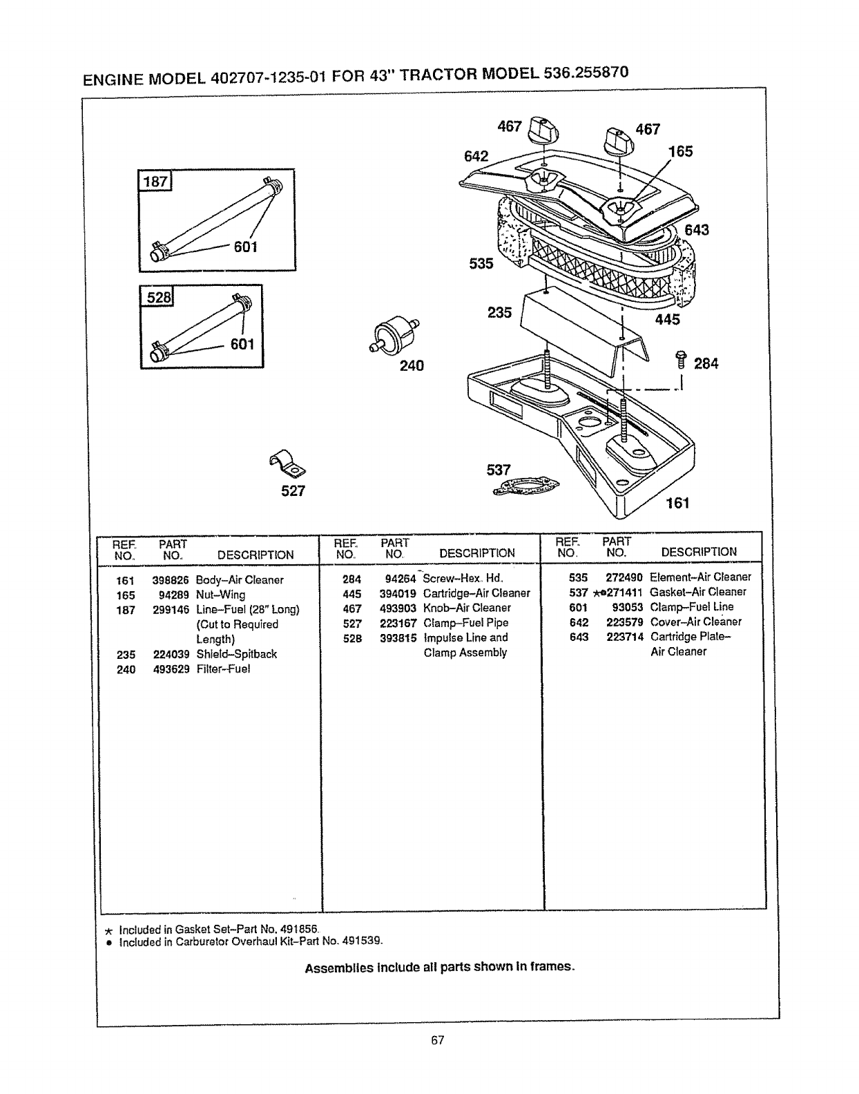
ENGINE MODEL 402707-1235-01 FOR 43" TRACTOR MODEL 536.255870
467
642
467
165
601
%
527
240
535
235
643
445
284
161
REE PART
NO. NO., DESCRIPTION
161 398826 Body-Air Cleaner
165 94289 Nut-Wing
187 299146 Line-Fuel (28" Long)
(Cut to Required
Length)
235 224039 Shleld-Spjtback
240 493629 Filter---Fuel
REF. PART
NO NO DESCRIPTION
284 g4264-Screw-Hex,, Hd_
445 394019 Cartridge-Air Cleaner
467 493903 Knob-Air Cleaner
527 223167 Clamp-Fuel Pipe
52B 393815 Impulse Lineand
Clamp Assembly
REF+ PART
NO, NO, DESCRIPTION
535 272490 Element-Nr Cleaner
537 _-e271411 Gasket-Air Cleaner
601 93053 Clamp--Fue! Line
642 223579 Cover-Air Cleaner
643 223714 CartridgePlate-
AirCleaner
:_ included in Gasket Set-Part No. 491856
= Included in Carburetor Overhaul Kit-Part No+49153g.
Assembiles include all parts shown In frames+
67
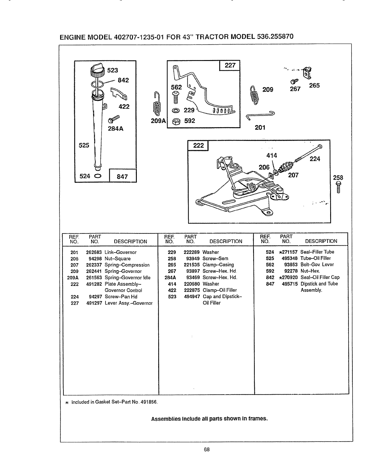
ENGINE MODEL 402707-1235-01 FOR 43" TRACTOR MODEL 536.255870
523
.I 842
%
422
284A
525
524 C> [ 847
209A
229
t_ 592
209
201
265
267
207
REE PART REE PART REE PART
NO. NO. DESCRIPTION NO. NO. DESCRIPTION NO. NO, DESCRIPTION
20i
2O6
2O7
209
209A
222
224
227
262683 Link-Governor
94298 Nut--Square
262337 Spring-Compression
262441 Spring-Governor
261563 Spring-Governor idle
491282 Plate Assembly-
Governor Controt
94297 Screw-Pan Hd
491297 Lever Ass¥.-Govemor
229 222289 Washer
258 93949 Screw-Sere
265 221535 Clamp-Casing
267 93897 Screw-Hex. Hd
284A 93469 Screw-Hex_ Hd.
414 220680 Washer
422 222875 Clamp-Oil Fillet
523 494947 Cap and Dipstick-
OilFiller
524 .271157 Seal-FillerTube
525 495348 Tube-OilFitler
562 93853 Bolt-Gov. Lever
592 92278 Nut-Hex,.
842 *270920 Seal-Oil FillerCap
847 495715 Dipstickand Tube
Assembly_
Included in Gasket Set-Part No. 491856.
Assemblies Include all parts shown In frames.
68
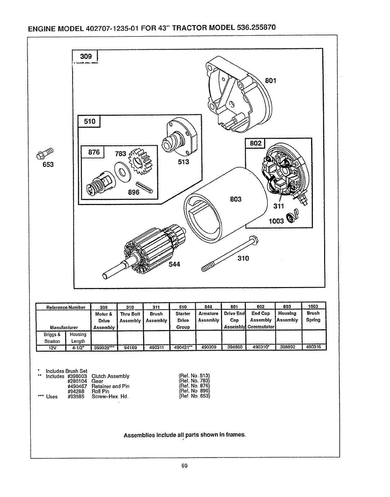
ENGINE MODEL 402707-1235-01 FOR 43" TRACTOR MODEL 536.255870
653
783
513
544
1
803 311
1003_
310
..... Reie;'enceNumber I 30g - 31o
Manufaclurer
........Briggs & Housing
Sttatton Length
12V 4-!t2"
311
Motor &
Drive
Assembly
399928""
510
Thru Boll Brush Starter
Assembly Assembly Drive
,Gro,up.......
94169 " 4903ii ....... 490421 ;°''''
544
Armature
Assembly
490309
801 8O2 803
. =
Drive End End Cap Housing
Csp Assembly Assembly
Assembly Commutator
394860 490310' 398892
1003
Brush
Spring
" InctudesBrush Set
"* Includes #398003 Ciutch Assemb_y
#280104 Gear
#490467 Retainer and Pin
#94288 Roll Pin
"** Uses #93585 Screw-Hex, Hal,
Refo No, 513)
Ref,, No,, 783)
Ref., No, 876)
Refo No 896)
Ref No, 653)
Assemblies Include all parts shown in frames,
69
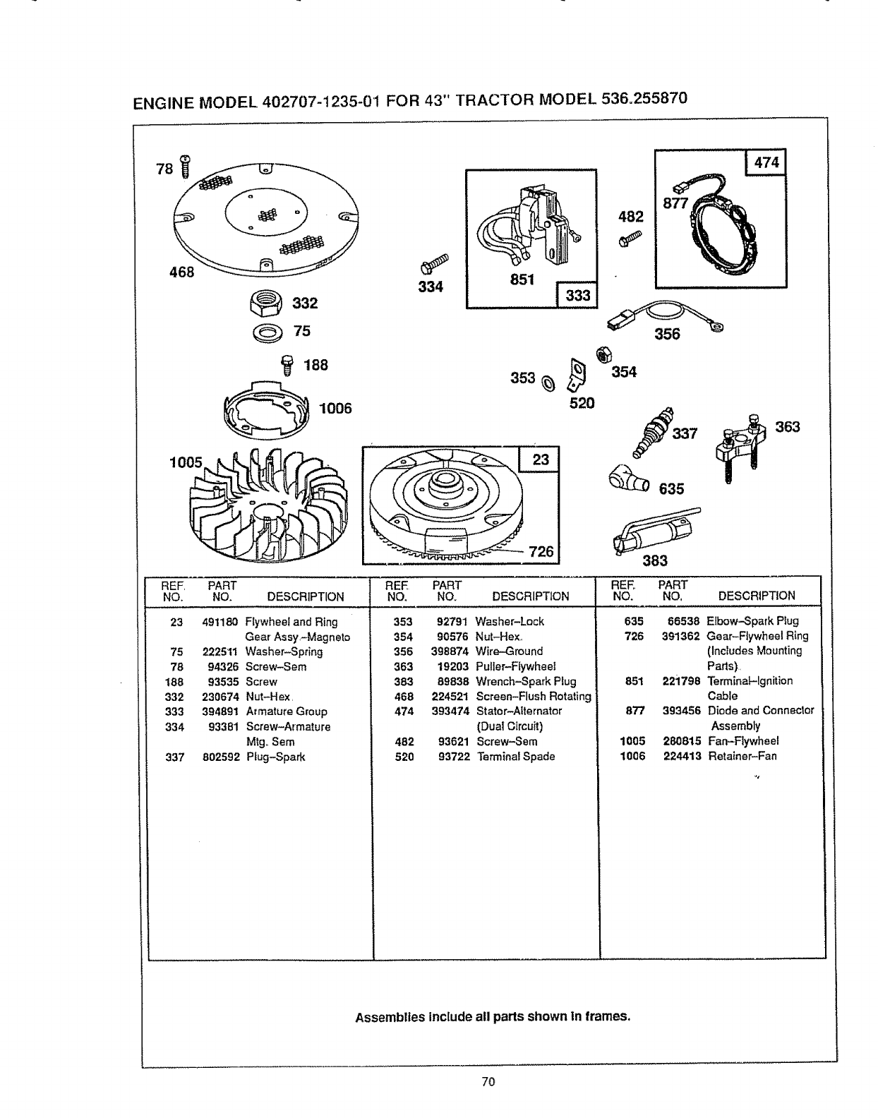
ENGINE MODEL 402707-1235-0'1 FOR 43" TRACTOR MODEL 536,255870
468
)332
75
168
1006
REF, PART
NO. NO. DESCRIPTION
23 491180 Flywheel and Ring
Gear Assy,-Magneto
75 222511 Washer-Spring
78 94326 Screw-Sere
189 93535 Screw
332 230674 Nut-Hex,
333 394891 Armature GIoup
334 93381 Screw-Armature
M_g,,Sere
337 802592 Pfug-Spark
334 851
482
353
52O
354
337
_635
363
383
REE PART
NO. NO. DESCRIPTION
353 92791 Washer-Lock
354 90576 Nut-Hex,
356 398874 Wire-Ground
363 19203 Puller-Flywheel
383 89838 Wrench-Spark P_ug
468 224521 Screen-Flush Rotating
474 393474 Stator-Ntemato_"
(Due| Circuit)
482 93621 Screw-Sem
520 93722 Terminal Spade
REE, PART
NO. NO, DESCRIPTION
635 86538 E_bow-Spark Plug
726 391362 Gear-Flywheel Ring
(Includes Mounting
Parts),
851 221798 Terminat-lgnition
Cable
877 393456 Diode and Connector
Assembly
1005 280815 Far_FIywheel
1006 224413 Retainer-Fan
Assemblies Include all parts shown In frames.
7O
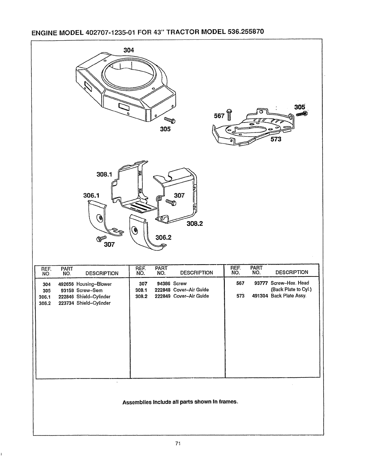
ENGINE MODEL 402707-1235-01 FOR 43" TRACTOR MODEL 536.255870
304
305
567
573
305
3o8.1
REF_ PART REE PART PART
NO. NO.. DESCRIPTION NO, NO. DESCRIPTION NO. DESCRIPTION
304 492656 Housing-Blower
305 93158 Screw-Sem
306_1 222846 Shield-Cylinder
306.2 223734 Shield-Cylinder
307 94386 Screw
308.1 222848 Cover-Air Guide
308,2 222849 Cover-Air Guide
REE
NO.
567
S73
93777 Screw-Hex. Head
(Back Prate to CyL)
491304 Back Plate Assy,
AssembliesInclude all parts shown in frames°
7I
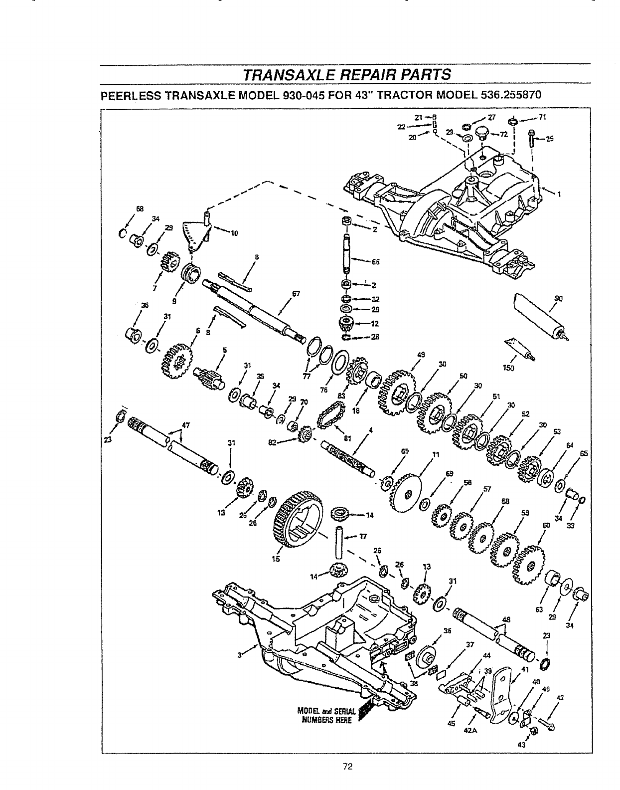
TRANSAXLE REPAIR PARTS
PEERLESS TRANSAXLE MODEL 930-045 FOR 43" TRACTOR MODEL 536.255870
68
34
57
72
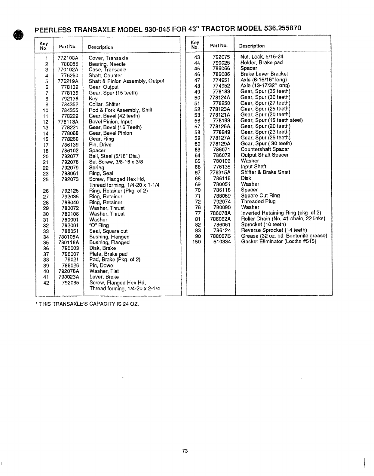
PEERLESS TRANSAXLE MODEL 930-045 FOR 43" TRACTOR MODEL 536.255870
Key
No,
1
2
3
6
7
8
9
10
11
12
13
14
15
t7
18
20
21
22
23
25
26
27
28
29
30
31
32
33
34
35
36
37
38
39
40
41
42
Part No,
772108A
780086
770102A
77626O
776219A
778139
778136
792136
784352
784355
778229
778113A
778221
778068
778260
786139
786102
792077
792078
792079
788061
792073
792125
792035
788O4O
78OO72
780108
780001
792001
788051
780105A
780118A
790003
790007
79O21
786O26
792076A
790023A
792085
Description
Cover, Transaxle
Bearing, Needle
Case, Transaxfe
Shaft, Counter
Shaft & Pinion Assembly, Output
Gear. Ou!put
Gear. Spur (I5 teeth)
Key
Collar, Shifter
Rod & Fork Assembly, Shift
Gear, Bevel (42 teeth)
Bevel Pinion, Input
Gear, Bevel (16 Teeth)
Gear, Bevel Pinion
Gear, Ring
Pin, Drive
Spacer
Ball, Steel (5/16_ Dia.)
Set Screw, 3t8o16 x 3/8
Spring
Ring, Seal
Screw, Flanged Hex Hd,
Thread forming, 114-20 x t-1/4
Ring, Retainer (Pkg. of 2)
Ring, Retainer
Ring, Retainer
Washer, Thrust
Washer, Thrust
Washer
"0" Ring
Seal, Square cut
Bushing, Flanged
Bushing, Flanged
Disk, Brake
Plate, Brake pad
Pad, Brake (Pkg. of 2)
Pin, Dowel
Washer, Fiat
Lever, Brake
Screw, Flanged Hex Hd,
Thread forming, 1/4-2o x 2-1/4
Key
No, Part No.
43 792075
44 79OO25
45 786O66
46 786O86
47 774951
48 774952
49 778183
5O 778124A
51 778250
52 778123A
53 778121A
56 778193
57 778126A
58 778249
59 778127A
60 778129A
63 786071
64 786072
65 780109
66 776135
67 776315A
68 786116
69 78OO51
7O 7861'18
7! 788069
72 792074
76 780090
77 788078A
81 786062A
82 786061
83 786124
9O 788067B
150 510334
Description
Nut, Lock, 5t16_24
Holder, Brake pad
Spacer
Brake Lever Bracket
Axle (8-15/16" long)
Axle (13-17/32" long)
Gear, Spur (35 teeth)
Gear, Spur (30 teeth)
Gear, Spur (27 teeth)
Gear, Spur (25 teeth)
Gear, Spur (20 teeth)
Gear, Spur (15 teeth steel)
Gear, Spur (20 teeth)
Gear, Spur (23 teeth)
Gear, Spur (25 teeth)
Gear, Spur ( 30 teeth)
Countershaft Spacer
Output Shaft Spacer
Washer
Input Shaft
Shifter & Brake Shaft
Disk
Washer
Spacer
Square Cut Ring
Threaded Plug
Washer
Inverted Retaining Ring (pkg..of 2)
Roller Chain (No..41 chain, 22 links)
Sprocket (I0 teeth)
Reverse Sprocket (14 teeth)
Grease (32 oz_.btl. Bentonite grease)
Gasket Eliminator (Loctite #515)
" THIS TRANSAXLE'S CAPACITY IS 24 OZ.
73
OWNER'S
MANUAL
MODEL NO.
536.255870
HOW TO ORDER
REPAIR PARTS
CRRFTSMRII
15.0 HP TWI
ALL=WHEEL
43" MOWER
CYL!
STEER
DECK
DER
6.-SPEED TRANSAXLE
LAWN TRACTOR
Eachtractor has itsown model number Each engine has itsown r:nodel
number
The Model Number for your tractor will be found on the model plate
located under the seat
The model number for your engine will be fou nd on the blower housing
of the engine
All parts may be ordered through Sears, Roebuck and Company
Service Centers and most Retail Stores,
WHEN ORDERING REPAIR PARTS, ALWAYS GIVE THE FOLLOW-
ING INFORMATION:
o PRODUCT - LAWN TRACTOR
o MODEL NUMBER - 536.255870
• ENGINE MODEL NUMBER., 402707-1235-01
• PART NUMBER
o PART DESCRIPTION
Your Sears merchandise has added value when you consider Sears
has service units nationwide staffed with Sears trained technicians ,
professional technicians specifically trained to insure that we meet
our pledge to you, we service what we sell,
SEARS, ROEBUCK AND CO., D/817WA, HOFFMAN ESTATES, IL 60179
327865 03/12/93 Printed in U S A
