Sears 536 884821 Users Manual
536.884821 to the manual 44e78a67-6363-43fa-b74b-4f20693e7172
2015-02-05
: Sears Sears-536-884821-Users-Manual-399486 sears-536-884821-users-manual-399486 sears pdf
Open the PDF directly: View PDF ![]() .
.
Page Count: 44
OWNER'S
MAHUAL
MODEL NO.
536.884821
Caution:
Read and Follow
All Safety Rules
and Instructions
Before Operating
This Equipment
CRRFr$IRN
5 HORSEPOWER
24" DUAL STAGE
FREE=WHEELIHG TRACK
SNOW THROWER
Optional Electric Start
• Assembly
="Operation
Maintenance
•Service and Adjustments
=Repair Parts
-- [ ................................................. .._.... _ _ _ _ ql Uq IIII1' ill
SEARS, ROEBUCK AND CO., Chicago, IL 60684 U.S.A.
..... ,................ inl ii ii '11 IIII I_ ...... Z .......
SAFETY RULES
CAUTION: ALWAYS DISCONNECT SPARK PLUG WIRE AND PLACE A
WIRE WHERE IT CANNOT CONTACT SPARK PLUG TO PREVENT
ACCIDENTAL STARTING WHEN SETTING-UP, TRANSPORTING, AD-
JUSTING OR MAKING REPAIRS.
IMPORTANT
SAFETY STANDARDS REQUIRE OPERATOR PRESENCE CONTROLS TO MINIMIZE THE
RISK OF INJURY. YOUR SNOW THROWER IS EQUIPPED WITH SUCH CONTROLS. DO NOT
ATTEMPT TO DEFEAT THE FUNCTION OF THE OPERATOR PRESENCE CONTROL UNDER
ANY CIRCUMSTANCES°
BEFORE USE
• Read the Owner's Manual carefully. Be thor-
oughly fan]iliar with the controls and the proper
use of the snow thrower. Know how to stop the
snow thrower and disengage the controls
quickly.
• Do not operate the snow thrower without wear-
ing adequate winter outer garments. Wear
footwear that will improve footing on slippery
surfaces. •
•Keep the area of operation clear of all persons,
particularly small chirdren, and pets.
•Thoroughly inspect the area where the snow
thrower isto be used and remove alldoormats,
sleds, boards, wires, and other foreign objects..
• Use extension cords and receptacles as
specified by the manufacturer for all snow
throwers with electric drive motors or with
factory-installed or optional starting motors
• Use only attachments and accessories ap-
provedby the manufacturer of the snow thrower
(such as eiectric starter kits, etc.)
oNever operate the snow lhrower without good
visibility or light. Always be sure of your foot}ng,
and keep a firm hold on the handles° Walk:
never run.
• This snow thrower is for use on sidewalks,
driveways, and other ground level surfaces.
CAUTION should be exercised whi(e using on
steep sloping surfaces. DO NOT USE SNOW
THROWER ON SURFACES ABOVE
GROUND LEVEL such as roofs of residences,
garages, porches or other such structures or
buildings,,
• Check shear bolts and other bolts at frequent
intervals for proper tightness to be sure the
snow thrower is in safe working condition.
• Disengage all clutches and shift into neutral
before starting the engine_
• ,Adjust the snow thrower height to clear gravel •
or crushed rock surface.
• Let engine and snow thrower adjust to outdoor
temperatures before starting to clear snow,
FUEL SAFETY
•Handle fuel with care; it is highly flammable.
•Use an approved fuel container,
• Check fuel supply before each use, aflowing
space for expansion as the heat of the engine
and/or sun can cause fuel to expand.
• Fill fuel tank outdoors withextreme care, Never
fill fuel tank indoors.
Replace fuel tank cap securely and wipe up
spilled fuel.
• Never remove fuel tank cap or add fuel to a
running engine or hot engine.
• Never store fuel or snow th rower wilh fuel in the
tank inside a building where fumes may reach
an open flame or spark.
OPERATING SAFETY
• Never atlow children or young teenagers to
operate the snow thrower and keep them away
while it is operating_ Never allow adults to
operate the snow thrower without proper in-
struction _Do not carry passengers.
•Always wear safety glasses or eye shields
during operation or while performing .'n adjust-
ment or repair to protect eyes from foreign
objects that may be thrown from the snow
thrower.
• Exercise extreme caution when operating on or
crossing gravel drives, walks, or roads. Stay
alert for hidden hazards or traffic.
•Do not put hands or feet near or under rotating
parts. Keep clear of the discharge opening at
all times,,
•Exercise caution to avoid slipping or falling,
especially when operating in reverse or back-
ing up.
•Do not clear snow across the face of slopes.
Exercise caution when changing direction on
slopes_ Do not attempt to clear'steep slopes.
Neveroperate the snowthrowerwithoutproper
guards, plates or other safety protective de-
vices in place.
SAFETY RULES
Never operate the snow thrower near glass
enclosures, automobiles, window wells, drop-
offs, and the like without proper adjustment of
the snow discharge angre. Keep children and
pets away_.
® Never operate the snow thrower at high trans-
port speeds on slippery surfaces_ Look behind
and use care when backing..
e Never direct discharge at bystanders or allow
anyone in front of the snow thrower.
® Do not run the engine indoors, except when
sta_ng the engine and for transporting the
snow thrower in or out of the building_ Open the
outside doors; exhaust fumes are dangerous
(containing CARBON MONOXIDE, an ODOR-
LESS and DEADLY GAS).
e Take all possible precautions when leaving the
snow thrower unattended_. Disengage the au-
gedimpeller, shift to neutral, stop engine, and
remove key,
e Do not overload the machine capacity by at-
tempting to clear snow at too fast a rate.
SAFE STORAGE
e Always refer to Owner's Manual instructions for
important details if the snow thrower is to be
stored for an extended period.
o Disengage power to the auger/impeller when
snow thrower is transported or not in use.
o Never store the snow thrower with fuel in the
fuel tank insidea building where ignitionsources
are present such as hot water and space
heaters, clothes dryers, and the likenAllow the
engine to cool before storing inany enclosure_
REPAIR/ADJUSTMENTS SAFETY
oAfter striking a foreign object, stop the engine
remove the wire from the spark plug or dis-
connect the cord from the electric motor°
Thoroughly inspect the snow thrower for any
damage and repair the damage before restart-
ing and operating the snow thrower°
® If the snow thrower should start to vibrate
abnormally, stop the engine or electric motor
and check immediately for the cause. Vibration
is generally a warning of trouble.,
® Stop the engine or electric motor whenever
you leave the operating position before un-
clogging the auger/impeller housing or dis-
charge guide, and when making any repairs,
adjustments, or inspections. Removewire form
spark plug or disconnect cord from electric
motor.
•When cleaning, repairing, or inspecting, make
certain the auger/impeller and all moving parts
have stopped. Disconnect the spark plug wire
and keep the wire away from the plug to pre-
vent accidental staRting.
o Never attempt to make any adjustments while
the engine is running (exceptwhen specifically
recommended in this manual).
e Maintain or replace safety and instruction la-
bels, as necessary.
o Run the snow thrower afew minutes after
throwing snow to prevent freeze-up of the
auger/impeller.
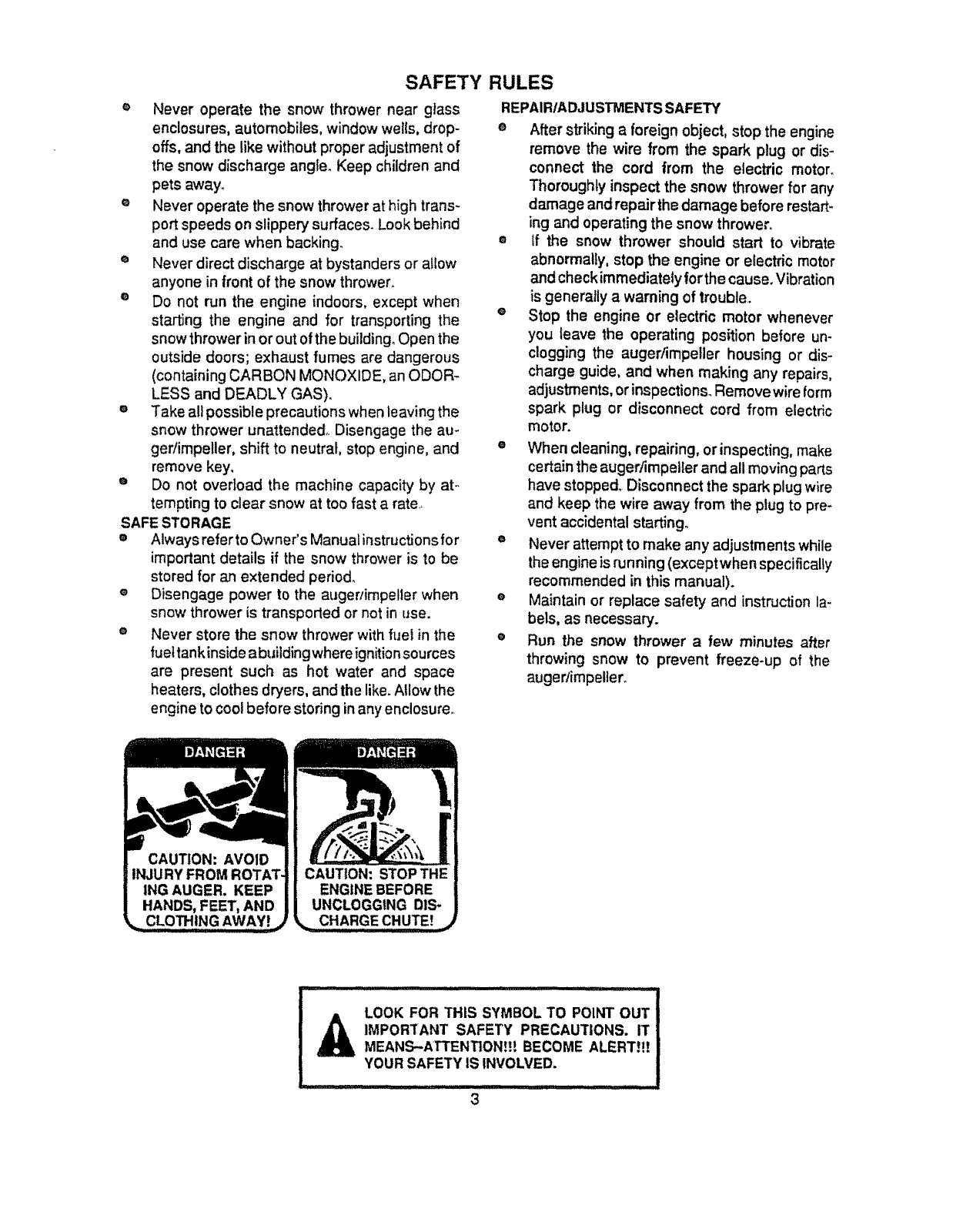
LOOK FOR THIS SYMBOL TO POINT OUT
_IMPOR'[ANT SAFETY PRECAUTIONS. IT
MEANS-ATTENTION!!! BECOME ALERT!I!
YOUR SAFETY IS INVOLVED.
3
CONGRATULATIONS on your purchaseof aSears
CraftsmanSnow_rower_ It hasbeen designed,engi-
neeredandmanufactured to giveyouthe bestpossible
dependabilityand performance.
Shouldyou experienceany problemyoucannot easily
remedy, please contact your nearest Sears Service
Center/Department. We have competent,welt4rained
techniciansandthe propertoolsto se_ce orrepairthis
uniL
Pleasereadandretainthismanual.'Theinstructionswill
enableyouto assembleand maintainyoursnowthrower
_mpedy. Alwaysobservethe =SAFETY RULES."
MODEL
NUMBER 536_884821
SERIAL
NUMBER
DATE OF
PURCHASE
THE MODEL AND SERIAL NUMBERS WiLL BE
FOUND ON A DECAL ATTACHED TO THE REAR
OF THE SNOW THROWER HOUSING_
YOU SHOULDRECORD BOTH SERIALNUMBER
AND DATE OF PURCHASEAND KEEP INA SAFE
PLACE FOR FUTURE REFERENCE°
MAINTENANCE AGREEMENT
A Sears Maintenance Agreement is available on this
product, ContactyournearestSears Storefor details_
PRODUCT SPECIFICATIONS
_SE POWER: 5 hp
:: :- ,,,,,,,,,,,,,,
DISPLACEMENT: 10.49
cu. In.
GASOLINE CAPACITY: 2 quart
Unleaded
........... m ,,,,,,,,, ..... -......... Hi
OIL (20 oz., Capacity): SAE 10W-30 or
5W-30"
SPARK PLUG :
(GAP .030 In.)
VALVE CLEARANCE:
Champion
RJ19LM
Intake: .010 In.
Exhaust: .010 in.
"S.AIF...5W-30 motor O" maybe used to make
starting easier In areas where the temperature Is
20° F or lower.
OPTIONAL ACCESSORY
Anelectricstarterkit(StockNo.,71-8894)is available for
this snowthrowerand may be ordered throughSears
Retailor CatologStores Installation instructions forthe
electricstarter are includedinthiskit.
CUSTOMER RESPONSIBILITIES
• Read andobservethe safetyrules°
• Followa regularscheduleinmaintaining,caring tot and usingyoursnowthrower.,
•FolJowthe instructions under"Maintenance"and =Storage"sectionsof thisowner'smanual
TWO YEAR LIMITED WARRANTY ON CRAFTSMAN
SNOW THROWER
Fortwo yearsfromthe date of purchase,whenthis Craftsman SnowThroweris maintained,lubricated
andtuned-upaccording to the instructionsinthe owner'smanual,Searswitlrepair,free of charge,any
detect inmaterialandworkmanship.
It thisCraftsmanSnowThroweris usedforcommercialor rentalpurposes,thiswarrantyappliesforonly
90 days from the date of purchase.
This warrantydoes notcoverthe following:
• Expendableitemswhichbecomeworndudngnormaluse,suchas sparkplugs,ddvebeltsand shear
p_so
Repairsnecessarybecause of operatorabuse ornegligence,including bent crankshaftsandthe failure
to maintainthe equipmentaccordingto the instructionscontainedinthe owner'smanual.
WARRANTY'SERVICE IS AVAILABLEBY RETURNING THE CRAFTSMANSNOW THROWER TO THE
NEAREST SEARS SERVICE CENTER/DEPARTMENTIN THE UNITED STATES. THIS WARRANTY
APPLIES ONLY WHILE THIS PRODUCTIS IN USE iN THE UNITED STATES,
Thiswan_antygivesyou speciticlegal rights,and youmay alsohave otherdghts whichmay varyfrom
stateto state.
SEARS, ROEBUCK AND CO. Department731CR_W,Sears Tower,Chicago,tL60684 ...................
.......... ::: ............,,,J=, i ..... ,,, ,,,,,, i uH= ........
4
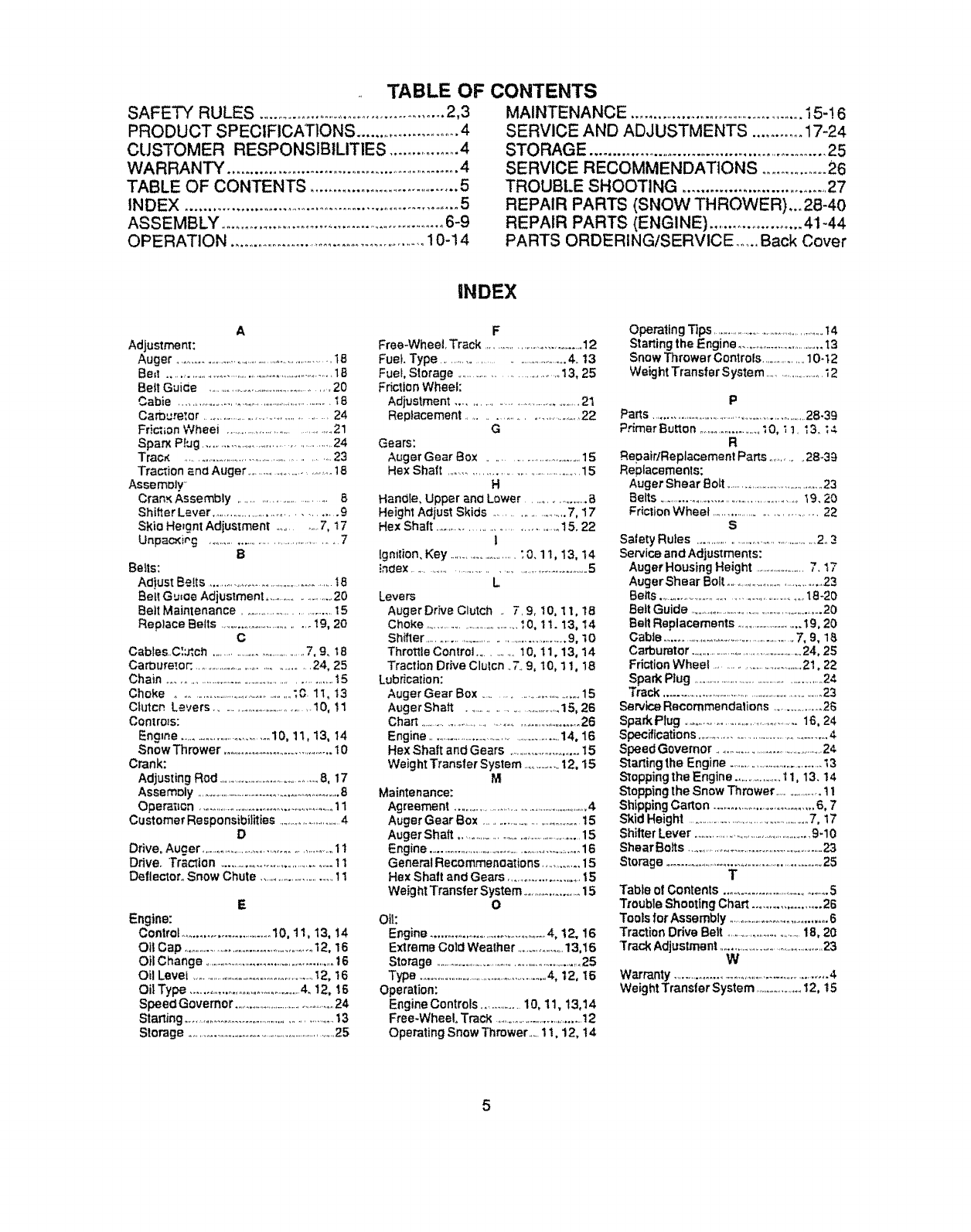
TABLE OF
SAFETY RULES ....................................................2,3
PRODUCT SPECIFICATIONS ...........................4
CUSTOMER RESPONSIBILITIES ................. 4
WARRANTY ...................................................... 4
TABLE OF CONTENTS .................................. 5
INDEX ............................................................. 5
ASSEMBLY ........................................................ 6-9
OPERATION ............................................. 10-14
CONTENTS
MAINTENANCE ..............................................15-! 6
SERVICE AND ADJUSTMENTS ........... 17-24
STORAGE ..................................................... 25
SERVICE RECOMMENDATIONS .................26
TROUBLE SHOOTING ................................. 27
REPAIR PARTS (SNOW THROWER),.. 2B-40
REPAIR PARTS (ENGINE) ...................... 41-44
PARTS ORDERING/SERVICE ........Back Cover
A
Adjustmen!:
Auger ..............................................................1B
Bm! ..................................................................18
Bett Gui_e ...............................................20
Cabie ............................................................t 8
Carburelor .............................................24
Frick;on Wheei ........................................21
Span P!ug ...............................................24
Track ....................................................23
Traction and Auger .................................18
Assemoly
Cran_ Assembly ........................... 8
ShiI!er Lever ......................................... 9
Skio Hergnt Adjustment ............. 7, 17
Unpac_iog ........................................... 7
B
Belts:
Ad)ust Belts ...........................................18
Belt Gu_oe Adjustment ........................20
Bett Maintenance .................................15
Replace Belts ..................................19, 20
C
Cables..C:_ch .....................................7, 9_ t 8
Ca_ure_.or: ...........................................24, 25
Chain ............................................................15
Choke .............................................;O. 11, i3
Clutch Levers ............................. 10, 11
Conlro_s:
Engine ....................................10, 11, t3, 14
SnowThrower .......................................t0
Crank:
Adjusting Rod ............................................8, 17
Assemoly ...........................................................8
Operaticn ......................................................11
Customer Responsibilities ............................4
D
Drive, Auger ..................................................1 t
Ddveo Traction .........................................11
De|lectoro Snow Chute ...............................11
E
Engine:
Control ...............................10, 11, 13, 14
Oil Cap .................................................12, 16
Oil Change ..................................................t6
Oil Level .....................................................12, 16
Oil Type .................................. 4. 12, 16
Speed Governor .................................................24
Starting ......................................................t3
Storage .............................................................25
iNDEX
F
Free-Wheel. Track ......................................12
Fuel. Type .............................................4. I3
Fuel, Storage ....................................13, 25
Friction Wheel:
Adjustment ...........................................21
Replacement ................................... 22
G
Gears:
Auger Gear Box .................................15
Hex Shaft ............................................ 15
H
Hanoi{e, Upper ano Lower ......................B
Height Adjust Skids .........................7, 17
Hex Shaft ................................... 15.22
l
[gnilion. Key ............................";0.1 I, 13, 14
!ndex ................................................................5
L
Levers
AugerDrive Clutch .. 7.9, 10, 1 Io 18
Choke .........................................I0, 1 I. 13, I4
Shffler .......................................................9, 10
Throttle Controt .......... I0, 11,13, 14
Traction Dr_e Clulcn ..7..9, 10, 11, 18
Lubrication:
Auger Gear Box ..................................15
Auger Shatt ..................................15, 26
Chart .................................................... 26
Engine ........................................................14, 16
Hex Shaft and Gears ...........................15
Weight Trans|er System ...............12, 15
M
Maintenance:
Agreement ............................................................4
Auger Gear Box .....................................15
Auger Shaft .................................................15
Engine ................................................................16
GeneraIRecommenoations ............. 15
Hex Shaft and Gears .........................15
Weight Transfer System ......................15
O
Oil:
Engine ..........................................4, 12, 16
Extreme Cold Weather ....................13,16
Storage ..............................................................25
Type ......................................................4, 12, 16
Operation:
Engine Controls ...............10,11, 13,14
Free-Whee!, Track .....................................12
Operating Snow Thrower.... 11, 12, t 4
Operating Tips ..................................................t4
Starting the Engine ......................................I3
Snow Thrower Controls...................10-12
WeightTransferSystem ..........................12
P
Parts ................................................................. 28-39
PrimerButton .....................;0, _ !. _3. ;4
R
RepatrlReplacement Parts ............28-39
Replacemenls:
Auger Shear Bolt ..........................................23
Belts ....................................................19.20
Friction Wheel ................................. 22
S
Satety Rules .................................................2.3
Service and Adjustments:
Auger Housing Height .......................7.17
Auger Shear Bolt ...........................................23
Betts .......................................................18-20
Belt Guide ............................................................20
Belt Replacements ..............................19,20
Cable ........................................................7, 9, 1
Carburetor ....................................................24, 25
Friction Wheel ..........................................22
Spark Rug ..........................................................24
Track .......................................................................23,
Se rvk?.eRecommendations ....................26
Spark Plug ............................................18, 24
Specifications ..................................................4
Speed Governor .................................................24
Starting the Engine .........................................t 3
Stopping the Engine .......................11, 13.14
Stopping the Snow Thrower ....................11
Shipping Oarton .....................................6, 7
Skid Height ......................................................7, 17
ShitTerLever .................................................9-I0
Shear Bofts .......................................................23
Storage ............................................................25
T
Table ol Contents ....................................5
Trouble Shooting Chart .................... 26
ToolsforAssembly .....................................6
Traction Drive Bert ...................................18, 20
Track Adjustmanl ..........................................23
W
Warranty .......................................................4
Weight Transter System ......................12, t5
5
ASSEMBLY
lllll ,,,, ................ ............................................. ii i!111 .................
THIS SNOW TI-IROWER HAS A TRACK DRIVE SYSTEM EQUIPPED TO GIVE
YOU FREE-WHEELING CAPABILITY
If yoursnowthrowermust be movedwithoutthe aidof the engine,it willbe easierto pullthe snowthrower
backwardby the handles, ratherthan pushing.For detailson howto use the free-wheelingcapability,see the
Track Drive/Free-WheelFeature paragraphinthe Operation sectionof thismanual
On startup, the track drive systemmay be tightbutwill loosenupas the snowthroweris used Afterfirstuse, check
the track for tensionand adjustif necessary.,See the "track Adjustmentparagraphin the Serviceand
Adjustmentssectionof this manual. Checktrack adjustmentand fastenersreguladyo
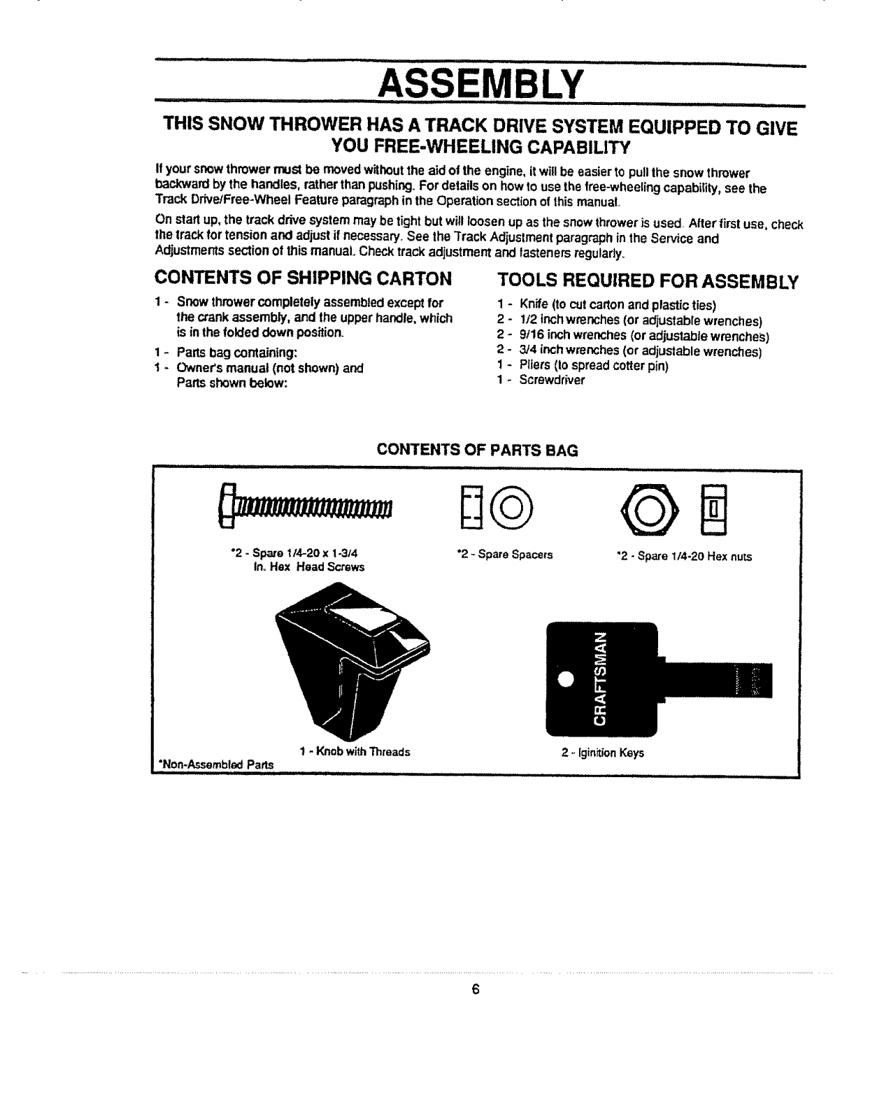
CONTENTS OF SHIPPING CARTON
1 - Snowthrowercompletelyassembledexceptfor
the crankassembly, and the upperhandle,which
is inthe foldeddownposition.
1 - Partsbag containing:
1 - Owner'smanual (not shown)and
Pans shownbelow:
TOOLS REQUIRED FOR ASSEMBLY
1 - Knife (to cut carton and plastic ties)
2 - 1/2 inch wrenches (or a_ustabre wrenches)
2 - 9f16 inch wrenches (or adjustable wrenches)
2-3/4 inch wrenches (or adjustable wrenches)
1 - Pliers (Io spread cotter pin)
1- Screwdriver
CONTENTS OF PARTS BAG
............... i I IIIII I II I I IIIIIIII II1'11111[11 I i, iiiiiiiiiiiiii ii i III
°2 -Spa_e 114-20x 1-3/4
In. Hox Head Screws "2 -Spare Spacers "2 - Spare 1/4-20 Hex nuts
1 - KnobwithThreads
"Non-AssembledParts
ill IH,ILIJ ,,,I[HIIII_',11'III ............ , ,
2_iginitionKeys
6
......................ASSE..........L¥ ..............'.............
Hi, _lll,lllll, .......... -.. ........................ ii ll.i ill _,_
,,, .__..:. ...................... .......................................... .,_:..
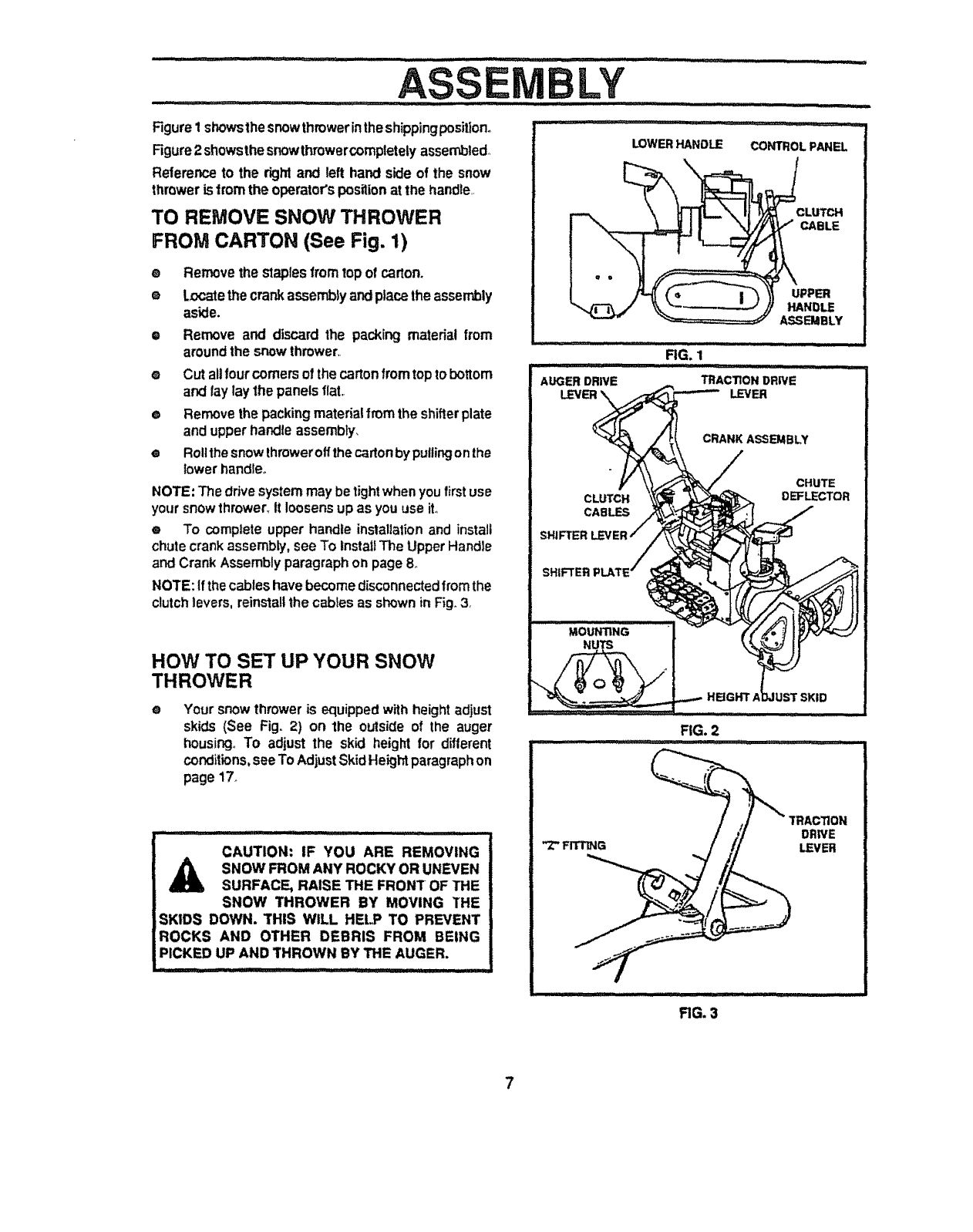
Figure1showsthe snowthmwerintheshippingposition.
Figure2 showsthe snowthrowercomptetetyassembled,
Reference to the righl and left hand side of the snow
throweris from the operator'spositionat the handle,,
TO REMOVE SNOW THROWER
FROM CARTON (See Fig. 1)
eRemovethe staplesfromtop of carton.
o Locate the crankassembly and placethe assembly
aside,
e Remove and discard the packing material from
aroundthe snowthrower,.
® Cut allfourcomersof the cartonfromtop to bottom
and lay laythe panelsflat,.
e Removethe packingmaterialfrom the shifterplate
and upperhandleassembly.
e Rollthesnowlhmweroffthecartonby pullingonthe
lower handle,,
NOTE: Thedrive systemmay betightwhenyoufirstuse
yoursnowthrower.It loosensup as youuse ito
e To completeupper handle installationand install
chutecrankassembly,see To InstallThe UpperHandle
and CrankAssemblyparagraphon page8.
NOTE: Ifthecableshave becomedisconnectedfromthe
clutchlevers, reinstallthe cablesas shownin Fig.3,
HOW TO SET UP YOUR SNOW
THROWER
oYour snow throweris equippedwithheightadjust
skids (See Fig. 2) on the outsideof the auger
housing,, To adjust the skid height for different
conditions, seeTo AdjustSkidHeightparagraphon
page 17._
CAUTION: IF YOU ARE REMOVING
,_ SNOW FROM ANY ROCKY OR UNEVEN
SURFACE, RAISE THE FRONT OF THE
SNOW THROWER BY MOVING THE
SKIDS DOWN. THIS WILL HEt.P TO PREVENT
ROCKS AND OTHER DEBRIS FROM BEING
PICKED UP AND THROWN BY THE AUGER,
.............. _;; _ .......... ....... ±
LOWER HANDLE CONTROL PANEL
CLUTCH
CABLE
UPPER
HANDLE
ASSEMBLY
CRANK ASSEMBLY
CLUTCH
CABLES
CHUTE
DEFLECTOR
SHIFTER
FIG. 2
"Z" FITTING
TRACTION
DRt!/E
LEVER
FIG. 3
7
iiillll, ii,i ii ,ll .... ,.................................... i/ J iui
MBLY
TO INSTALL THE UPPER HANDLE AND
CRANK ASSEMBLY
• Removethe screws,flatwashers,to.washers and
hexnutssecudngthe shifterplateinthe lowerholes
of the lower handle..
• Loosen,t_Jtdonotremove,thescrews,flatwashers,
lockwashers, and hex nutsinthe upperholesof the
lowerhandle_
• Raiseupperhandle into operatingposition.,Upper
handleshouldbe to the outsideof the lower handle
and shifterplate to the inside.
• Replacethe screws0flatwashers,lockwashers, and
hex nutsthroughthehandlesandshifterplate.Donot
lightenuntilallbolts are in ptace_T'_jhtenlefthand
sidefirst.
NOTE: Unless you have the assistanceof anotherper-
son,itmay be easierto installonesideofthehandleatthe
time.
• Tightenthe screw,flat'washer,Iockwasherand hex
nutat the upperdght hand holeonly (See Fig,4A),
• Removethe screw,flatwasher,Iockwasherandhex
nutfrom the upperlefthand holeofthe lowerhandle
and discard,
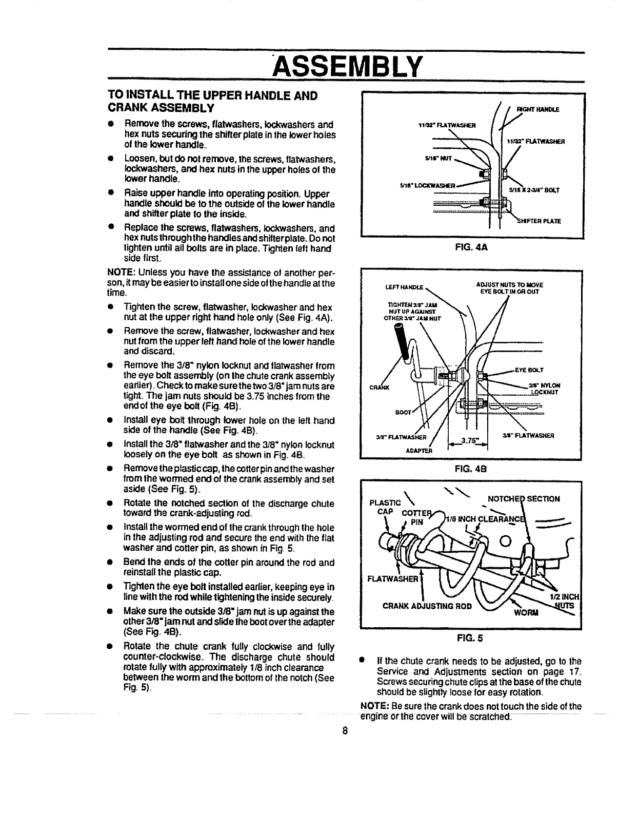
• Removethe 3/8" nyloniocknutand flatwasherfrom
theeye bolt assembly(onlhe chutecrankassembly
eadier)_Checktomakesurethetwo3/8"jamnutsare
tight.The jam nutsshouldbe 3.75 inches fromthe
endof the eye bolt (Fig. 4B).
• Installeye bolt throughlower hole on the left hand
sideof the handle(See Fig.,4B)_
• Installthe 3/8"ftatwasherandthe3/8"nylonlocknut
looselyon the eye bolt as showninFig_4Bo
• Removetheptasticcap,thecotterpinandthewasher
from the wormedend ofthe crankassemblyandset
aside (See Fig°5)_
• Rotate the notchedsectionof the dischargechute
towardthe crank*adjustingrod..
• Installthe wormed endof thecrankthroughthe hole
in the adjustingrod and securethe endwiththe flat
washer andcotterpin, as shownin Fig.5
•Bendthe ends of the cotter pin aroundthe rodand
reinstallthe plasticcap.
•Tighten the eye bolt installedearlier, keepingeye in
linewiththe rodwhiletighteningthe insidesecurely
• Make surethe outside3/8" jam nutis upagainstthe
other3/8"jam nutandslidethebootoverthe adapter
(See F_,.4B).
•Rotate the chute crank fully clockwiseand fully
counter-clockwise, The discharge chute should
rotatefullywith approximately 1/8 inchclearance
betweenthe wormand the bottom of the notch(See
Fig.5).
_'tB"
FIG. 4A
=_
FIG. 5
•If the chutecrankneedsto be adjusted, go to the
Service and Adjustments section on page 17_
Screwssecuringchuteclipsatthebase ofthechute
shouldbe slightlyloose for easyrotation.
NOTE: Besurethe crankdoes nottouchthe sideofthe
................................................. engineorthe coverwillbe scratched,:......................................................................
8
ASS LY
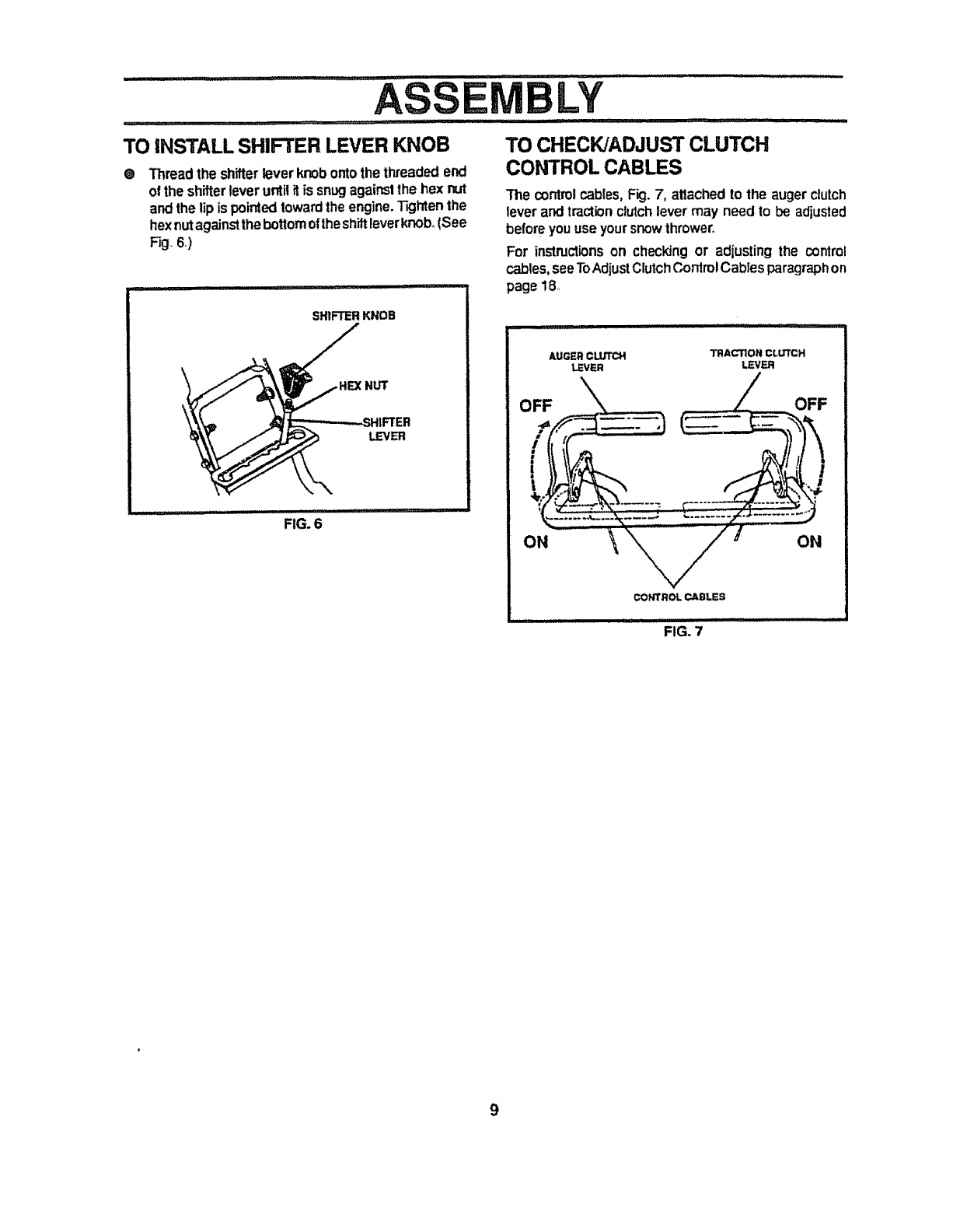
TO iNSTALL SHIFTER LEVER KNOB
0Threadthe shifterlever knobontothe threadedend
of the shifterlever untilitis snug against the hex rut
andthe lipis pointedtowardthe engine.T_jhten the
hexnutagainstthebottomoftheshiftleverknob_(See
Fig,6,)
..................... i ,,I,L
SNIFTER KNOB
NUT
LEVER
FIG. 6
,llll
TO CHECKJADJUST CLUTCH
CONTROL CABLES
The controlcables,Fig. 7, attachedto the augerclutch
lever andtractionclutchlever may needto be adjusted
before youuse yoursnowthrower,,
For instructionson checkingor adjusting the control
cables,seeToAdjustClutchControlCablesparagraphon
page 18,
i I I i,,11 iiiiiiiiiiii _T : :
AUGER CLUTCH TRACTION CLUTCH
LEVER LEVER
OFF OFF
ON ON
CONTROL CABLES
................F,G.7
.......... IJWIILIIlU III IIII , , iiiiii IIIIIIIII I I II I IIIIII _II I II i ..... III1'1111i ii
OPERA: ION
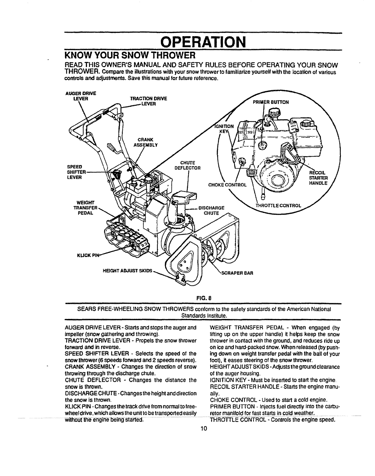
KNOwYOUR SNow THROWER .............................................................................
READ THIS OWNER'S MANUAL AND SAFETY RULES BEFORE OPERATING YOUR SNOW
THROWER. Comparethe illustrationswithyoursnowthrowerto famgiarizeyourseffwiththe locationof vadous
commlsand adjustments.Save thismanualforfuturereference,
AUGERDRIVE
LEVER 'TRACTION DRNE PRIMER Bbq'TON
SPEED
LEVER
CRANK
ASSEMBLY
CHUTE
DEFLECTOR
STARTER
CHOKE CONTROL HANDLE
WEmHr
PEDAL CHUTE
THROTTLE CONTROL
HEIGHT ADJUST
FIG. 8
SEARS FREE-WHEELING SNOW THROWERS conformto the safetystandardsof the AmericanNational
StandardsInstitute.
AUGER DRIVE LEVER-Starts andstopsthe augerand
impeller(snow gatttering and throwing).
"rRACTIONDRIVE LEVER - Propelsthe snow thrower
forwardand inreverse,
SPEED SHIFTER LEVER _ Selects the speed of the
snowthrower(6 speedsforwardand2 speedsreverse).
CRANK ASSEMBLY - Changesthe direction of snow
throwingthroughthe dischargechute.
CHUTE DEFLECTOR -Changes the distance the
snowis thrown.
DISCHARGECHUTE- Changestheheightanddirection
the snow isthrown
KLICKPIN -Changesthe trackdrive fromnormaltofree-
WEIGHT TRANSFER PEDAL * When engaged (by
lifting up on the upperhandle)it helps keep the snow
throwerin contactwiththe ground,and reducesrideup
on iceand hard-packedsnow.Whenreleased(bypush-
ingdownon weighttransferpedal withthe ball of your
foot), it eases steedng ofthe snowthrower.
HEIGHTADJUSTSKIDS -Adjuststhe groundclearance
of the auger housing_
IGNITION KEY. Mustbe insertedto startthe engine.
RECOILSTARTER HANDLE- Startsthe enginemanu-
ally,,
CHOKE CONTROL -Usedto start a cotdengine.
PRIMER BUTTON -Injectsfuel directlyintothe cart_u-
wheeldrive,whk_haltowstheunittobettansportedeasily retormanifoldforfaststars incoldweather.
................................... ........................................................................................................................ RO LE iheengir e ............
10
.............. i//_. ii, ii iii iiii ii i i i i iiiJllllllllllJll i 11111111iii,
OPERATIO
I I II1,1 I11 iii1[11 i,iir
Ieyes, whichcan result in severeeyedamage. Always wear safetyglasses or eye
shieldswhile operatingthe snowthrower.
We recommend standardsafety glassesavailable at SEARS Retail or Catalog
Storesor a widevisionsafetymaskfor overyour glasses°
...... r=_l "lllqll_ll'lll" LI_
HOW TO USE YOUR SNOW
THROWER
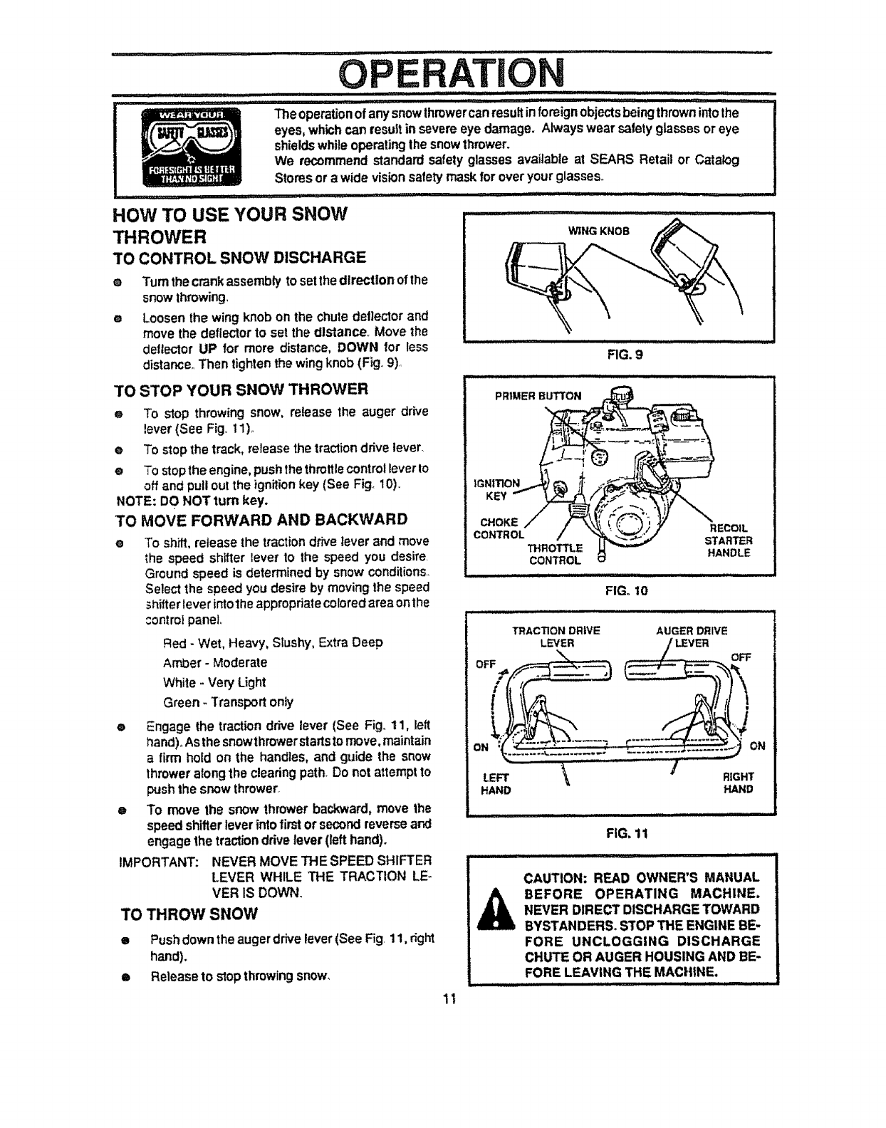
TO CONTROL SNOW DISCHARGE
e Turnthecrankassemblyto setthedirection of the
snowthrowing,
e Loosenthe wing knobon the chutedeflectorand
move the deflectorto set the distance Move the
deflectorUP for more distance,DOWN for less
distance Then tightenthe wingknob(Fig 9)_
TO STOP YOUR SNOW THROWER
e To stop throwingsnow, release the auger drive
lever{See Fig 11)o
e To stopthe track, releasethe tractiondrive lever.
e To stoptheengine,pushthe throttlecontrolleverto
offand pull outthe ignitionkey (See Fig, 10)
NOTE: DO NOT turn key.
TO MOVE FORWARD AND BACKWARD
• To shift,release the tractiondrive leverand move
the speed shifterlever to the speed you desire
Ground speed is determinedby snowconditions
Select the speedyou desireby movingthe speed
_hifferlever intothe appropriatecoloredareaonthe
control panel,
Red - Wet, Heavy, Slushy, Extra Deep
Amber - Moderate
White - Very Light
Green - Transport only
®Engage the traction drive lever (See Fig. 11, left
hand),,As the snowthrowerstarts to move, maintain
a firm hold on the handles, and guide the snow
throweralong the cleadng path Do not attempt to
push the snow thrower.
• To move the snow throwerbackward,move the
speedshifterleverinto first orsecondreverseand
engage the tractiondrivelever (lefthand).
IMPORTANT: NEVER MOVE THE SPEED SHIFTER
LEVER WHILE THE TRACTION LE-
VER IS DOWN
TO THROW SNOW
ePushdown the auger drive lever(See Fig, 11, dght
hand).
e Release to stop throwing snow.
iiiiiii :
WING KNOB
RG. 9
PRIMER BUTTON
IGNITION
KEY
CHOKE RECOIL
CONTROL STARTER
THROTTLE HANDLE
CONTROL
ill i,,,H ii :
FIG. 10
TRACTION DRIVE AUGER DRIVE
LEVER
LEFT RIGHT
HAND HAND
FIG. 11
_J LII III IIIIIIIII IIIIIIIIIIIIIII :: ....... _ ,,
CAUTION: READ OWNER'S MANUAL
BEFORE OPERATING MACHINE.
NEVER DIRECT DISCHARGETOWARD
BYSTANDERS. STOP THE ENGINE BE,.
FORE UNCLOGGING DISCHARGE
CHUTE OR AUGER HOUSING AND BE-
FORE LEAVING THE MACHINE.
11
OPERATION
...... 7IJIIIIMII IIIjIIIIIILI] ii LI'1 ill i Ill I iii iiil:llljii i ]_ lI illiilgilllJ J ........ II1'11 ill II II
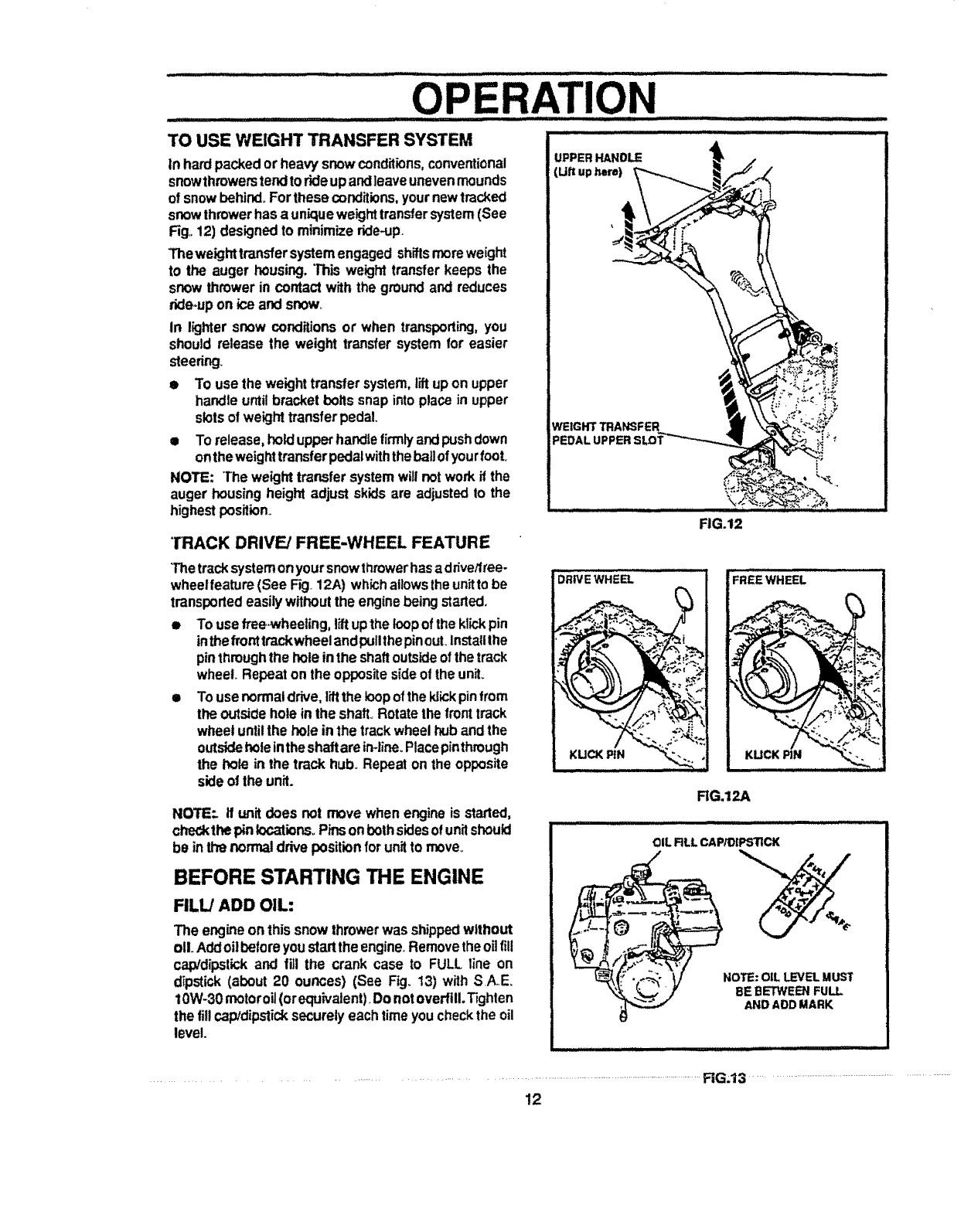
TO USE WEIGHT TRANSFER SYSTEM ....................................
tn hardpackedor heavy snowconditions,conventional
snowthrowerstendtorideupandleaveunevenmounds
of snowbehind.Forthese conditions, yournewtracked
snowthrowerhas a uniqueweighttransfersystem (See
Fig,,12) designedto minimize dde4Jp.
Theweight transfersystemengaged shiftsmoreweight
to the auger housing,This weight transferkeeps the
snowthrowerin con*actwith the groundand reduces
ride-upon ice andsnow°
in lighter snow conditions or when transporting,you
should release the weight transfer systemfor easier
steedng.
• To use the weighttransfer system,tiltupon upper
handleuntilbracket boltssnap intoplace in upper
slotsof weighttransferpedal.
• To release,hold upperhandlefirmlyand pushdown
onthe weighttransferpedalwiththebailof yourfool
NOTE: "[heweight transfersystemwill notwork if the
auger housingheightadjust skids are adjustedto the
highestposition.
TRACK DRIVE/FREE-WHEEL FEATURE
(Uftuphere)
WEIGHT TRANSFER
PEDAL UPPERSLOT'_
FIG.12
Thetracksystemonyoursnowthrowerhasaddvetlree-
wheelfeature(See Fig 12A) whichallowstheunitto be
transportedeasilywithoutthe enginebeingstarted.
• Touse free_heeling, liftupthe loopof the klickpin
inthefronttrack wheelandpullthe pinouLInstallIhe
pinthroughthe holeinthe shaftoutsideofthe track
wheel Repeaton the oppositesideof the unit.
• Touse normaldrive,liftthe loopoftheIdickpinfrom
the outsidehole in the shaft.,Rotatethe fronttrack
wheeluntilthe hole in the trackwheelhuband the
outsideholeintheshaftareirHine_Placepinthrough
the bole in the track hub_Repeat on the opposite
sideof the unit.
NOTE:. tf unit does not move when engineis started,
checkthepin locations°Pinsonbothsidesofunitshould
be inthe normaldrive positionforunitto move_
BEFORE STARTING THE ENGINE
FILL/ADD OIL:
The engineon thissnowthrowerwasshippedwithout
oILAddoilbefore youstartthe engine_Removetheoil lilt
cap!dipstickand fill the crank case to FULL line on
d_pstick(about 20 ounces) (See Fig. 13) with SA, E.
10W-30motoroil (orequivalent)_Donotoverfill.Tighten
the fillcap/dipsticksecurelyeachtime youcheckthe oil
level.
DRIVE WHEEL
RG.12A
i ......... ..........
.....
'_ _tk_,' ,/' BE1BETWEENFULL
AND ADD MARK
...........................................................................................................RGJ3 ...........................................................................................
!2
'i ii , ,i ,r, , ii, L I1'I I II,lll ,.I
OP TI
FILL GAS:
Fill the fuel tank with clean, fresh, unleaded grade
autornotivegasoline.Besurethatthecontaineryoupour
the gasolinefrom is clean and free from rust or other
foreignparticles.Never use gasolinethatmay be stale
trom tongperiodsof storage inthe container.,
NOTE: S,,A,,E_5W-30 motor oil may be used to make
startingeasier inareaswherethe temperatureis 20" F,
or lower,,
WARNING: Experience indicates that aP..oholblended
fuels (called gasohot orthose using ethanol or methanol)
can attract moisture which leads to separation and for-
mation of acids during storage. Acidic gas can damage
the fuel system of an engine while in storage
To avoid engine problems, the fuel system should be
emptied before storage for 30 days or linger Start the
engine and let it rununtil the fuel lines and carburetor are
empty. Use the carburetor bowl drain to empty residual
gasoline from the float chamber (Fig 42) Use fresh fuel
next season° (See Storage instructions on page 25 for
additional information°)
Never use engine or carburetor cleaner products in the
fuel tank or permanent damage may occur.
.... i,i ill,ill i, ii ill, i ii
CAuTIoN:GASOL,NEisFLA"ABLE
_L AND CAUTION MUST BE USED WHEN
HANDUNGORSTORINGITo
DONOTFILLFUELTANKWHILESNOW
THROWERRUNN,NG,WHENrrISHOT,OR
WHENSNOWTHROWERSINANENCLOSED
AREA.
KEEP AWAY FROM OPEN FLAMEOR AN ELEC-
TRICAL SPARK AND DO NOT SMOKE WHILE
FILLING THE FUEL TANK.
NEVER FILL THE TANK COMPLETELY. FILL
THETANKTO WITHIN 1/4"-1/2" FROMTHETOP
TO PROVIDE SPACE FOREXPANSIONOF FUEL
ALWAYS FILL FUEL TANK OUTDOORS AND
USE AFUNNEL OR SPOUT TO PREVENTSPILL-
ING.
MAKE SURE TO WIPE UP ANY SPILLED FUEL
BEFORE STARTING THE ENGINE.
STORE GASOUNE IN ACLEAN, APPROVED
CONTAINER AND KEEPTHE CAP IN PLACE ON
THE CONTAINER.
i .............. ......
.............. ii ,,
CAUTION: NEVER RUN ENGINE IN-
DOORS ORIN ENCLOSED, POORLY
VENTILATED AREAS. ENGINE EX-
HAUST CONTAINS CARBON MON-
OXIDE, AN ODORLESS AND DEADLY GAS.
KEEP HANDS, FEET, HAIR AND LOOSE
CLOTHINGAWAY FROMANY MOVING PARTS
ON ENGINE AND SNOW THROWER.
WARNING: TEMPERATUREOF MUFFLERAND
NEARBY AREAS MAY EXCEED150° F. AVOID
THESE AREAS.
DO NOTALLOW CHILDRENOR YOUNG TEEN-
AGERS TO OPERATE OR BE NEAR SNOW
THROWER WHILE IT IS OPERATING.
TO STOP ENGINE
e To stopengine, movethe throttlecontrolleverto
STOP positionandremovekey, Keep the keyin a
safeplace.,Theenginewillnot_lart withoutthekey,_
TO START ENGINE
Besurethatthe enginehassufficientoil Beforestarling
the engine,be certainthat youhave read the folliwing
information:
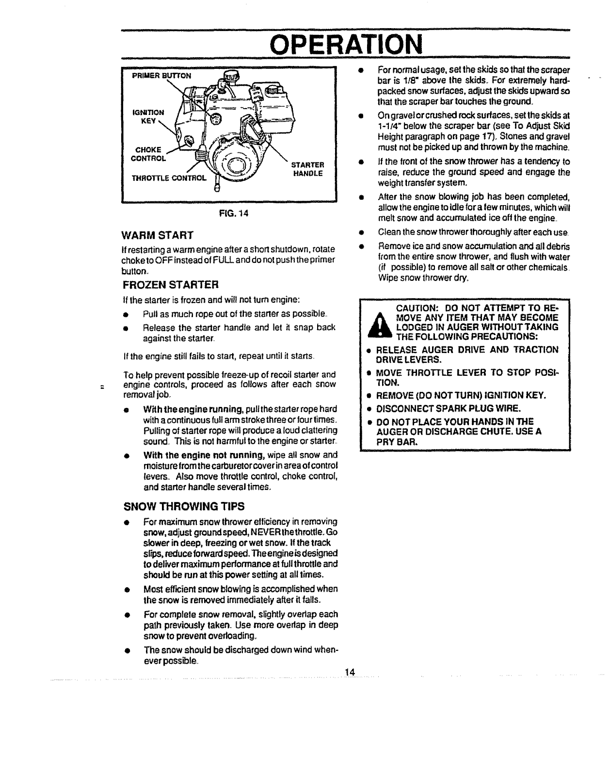
COLD START (See Fig. 14)
eBe suretheaugerddve andthetractiondrivelevers
are inthe disengagedRELEASEDposition,
Movethe throttle controlupto RUN position.tp
OPush the key into the ignition slot found in parts
page, Be sure itsnaps into place._DO NOT TURN
KEY., Place extra key in a safe place.,
oRotatechokecontro!to FULLchokeposition,
o Press the primer I_Jtton in cold weather Press
twoor three times,whifekeepingyour linger over
the vent hole on the pdmer button_ Additional
pdming may be necessary for the firststart if the
temperature is below t5 ° F,,Do notprime it tem-
perature is above 50°F.
=, Pull the starter handle rapidly. Do not allow the
handle to snap back,but allow it to rewind slowly
while keeping a firm hold onthe starterhandle,,
® As the engine warms up and begins to operate
evenly, rotate the choke knob slowly to OFF
position°ffthe enginefalters,returnto FULLchoke,
thenslowtymove to OFF chokeposition_
NOTE: Before usingthe snowthrower, allow the engine
towarm up forafewminutesbecause the engine willnot
developfult poweruntil itreachesoperating temperature°
•Run the engine at or near the top speed when
throwingsnow.,
13
ii_pr_ iiiiii ........... it 7 ............... IIIIg JL iiiiiii lIIIILIII'IIIII lilt ._: _.Ill'It'IJI
OPERATION
e
iiiiii, , i, iii i1,111i ........................................
PRIMER BUTTON
IGNITION
KEY
CHOKE
CONTROL STARTER
THROTTLE CONTROL HANDLE
FIG, 14
WARM START
tf restarting awarm engine after a shortshutdown, rotate
choketo OFFinstead of FULL anddo notpush theprimer
button..
FROZEN STARTER
For normalusage,setthe skidsso thai the scraper
bar is 1/8" above the skids, Fo_"extremelyhard-
packedsnowsurfaces,adjustthe skids upwardso
thatthe scraperbar touchesthe ground.,
•Ongravel orcrushedrocksurfaces,settheskidsat
t-1/4" below the scraperbar (see To AdjustSkid
Heightparagraphon page t7). Stones andgravel
must notbe pickedupand thrownby the machine,.
•If the front of the snowthrowerhas a tendencyto
raise, reduce the groundspeed and engage the
weighttransfersystem.
•Alter the snowblowing job has been completed,
allowthe engineto idlefora few minutes, whichwill
meltsnowand accumulated iceoft the engine
•Clean thesnowthrower thoroughlyafter eachuse.
• Removeice andsnowaccumulation and alldebris
fromthe entiresnow thrower,and flush withwater
(if possible)to removeallsaltor otherchemicals.
Wipe snow throwerdry,,
If the starteris frozenand wiltnotturnengine:
• Pull as much rope out ofthe starteras possible.,
•Release the starter handle and let it snap back
againstthestarter.
If the enginestillfails to start,repeat untilit starts_
To help preventpossiblefreeze-upof recoilstarterand
engine controls,proceed as fol!ows after each snow
removaljob..
o With the engine running, pull thestarter ropehard
witha continuous fullarmstrokethreeorfourtimes.
Pullingof starterropewillproducea loud clattering
sound.. This is notharmfulto the engineorstarter..
• With the engine not running, wipeall snowand
moisturefromthecarburetorcoverinarea ofcontrol
levers., Also move throttlecontrol, chokecontrol,
and starterhandleseveraltimes,
i=l ..... -- : .......... ::.:_ .... i
CAUTION: DO NOT ATTEMPT TO RE,,
MOVE ANY ITEM THAT MAY BECOME
LODGED IN AUGER WITHOUT TAKING
THE FOLLOWING PRECAUTIONS:
e RELEASE AUGER DRIVE AND TRACTION
DRIVE LEVERS.
• MOVE THROTTLE LEVER TO STOP POSI-
TION.
• REMOVE (DO NOTTURN) IGNITION KEY,
• DISCONNECT SPARK PLUG WIRE.
•DO NOT PLACE YOUR HANDS IN THE
AUGER OR DISCHARGE CHUTE. USE A
PRY BAR.
illl i ' ' ............
SNOW THROWING TIPS
•Formaximum snowthrower efficiencyin removing
snow,adjustgroundspeed, NEVERthethrottle. Go
slowerin deep, freezingorwet snow.It thetrack
sr_s,reduceforwardspeed,Theengineisdesigned
to delivermaximum performanceatfullthrottleand
shouldbe runat thispowersettingat alltimes.
• Mostefficientsnowblowingis accomplishedwhen
the snowis removedimmediatelyafter it falls.
• For completesnow removal,slightlyoverlapeach
path previouslytaken. Use more overlapin deep
snowto prevent ovedoading_
• The snowshouldbe dischargeddownwindwhen-
ever possible..
................................................................. !4 ...........
GENERAL RECOMMENDATIONS
The warrantyonthissnowthrowerdoesnotcoveritems
that have been subjectedto operator abuseor negli-
gence,.To receivefull value from the warranty,operator
must maintain snowthrower as instructedinthismanual.
MAINTENANCE
Some adjustments will need to be made periodically to
propedy mainlain your snow thrower,
All adjustments inthe Service and Adjustments section of
this manual should be checked at feast once each
season,
AFTER FIRST USE
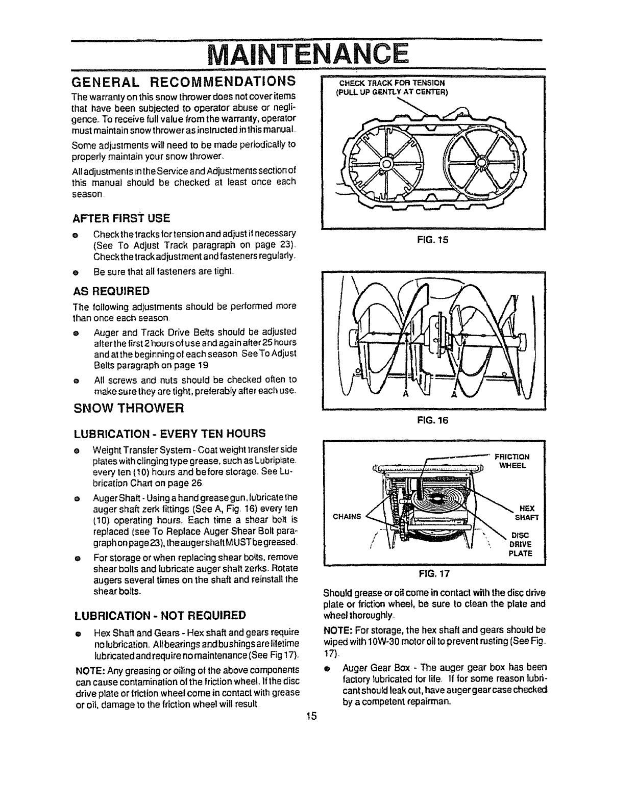
eCheck thetracks for tension and adjust ifnecessary
(See To Adjust Track paragraph on page 23).
Checkthe track adjustment and fasteners reguladyr
(PULL UP GENTLY AT CENTER)
FIG. 15
eBe sure that all tasteners are tight..
AS REQUIRED
The following adjustments should be performed more
than once each season.
eAuger and Track Drive Belts shouid be adjusted
alter the first 2 hours of use and again after 25 hours
and at the beginning o! each season SeeTo Adjust
Belts paragraph on page 19
e All screws and nuts should be checked often to
make sure they are tight, pre{erabty alter each use.
SNOW THROWER
LUBRICATION -EVERY TEN HOURS
•Weight Transter System _Coat weight transler side
plates with clinging type grease, such as Lubrip_ate,
every ten (10) hours and before storage,, See Lu-
brication Chart on page 26
e Auger Shaft- Using a hand greasegun,lubricatethe
auger shaft zerk fittings (See A, Fig 16) every ten
(10) operating hours, Each time a shear bolt is
replaced (see TO Replace Auger Shear Bolt para -
graph on page 23),the augershaft MUSTbe greased,
e For storage or when replacing shear boils, remove
shear boils and lubricate auger shaft zed_s,,Rotate
augers several times on the shaft and reinstal! the
shear bolts.
LUBRICATION - NOT REQUIRED
eHex Shaft and Gears- Hex shaft and gears require
nolubrication, Altbearings andbushings areliletime
lubricated andrequireno maintenance(See Fig 17),,
NOTE: Any greasing oroiling of the above components
can cause contamination ol the frictionwheel, Ifthe disc
driveplateor friction wheel come in contact with grease
or oil, damage to the friction wheel will result,,
............ ,,r,;,,'r'' "
FIG. 16
FRICTION
WHEEL
CHAINS HEX
SHAFT
Should grease oroilcomeincontactwiththe discdrive
plate or frictionwheel, be sure to clean the plate and
wheelthoroughly_
NOTE: Forstorage,the hexshaft and gears shouldbe
wipedwith10W-30motoroittopreventresting (SeeFig..
17)_
eAuger Gear Box - The auger gear box has been
factory lubricatedfor lite If forsome reason lubri-
cantshould leak out, have augergearcase checked
by a competent repairrnan_
15
1111 1111,11,1111111, 1111111111111 I I' iii , i , i [ii I 111111111111,,, 111 ::: IILI
TENANCE : '11'1'1 I t' i ........
ENGINE ....:
LUBRICATION
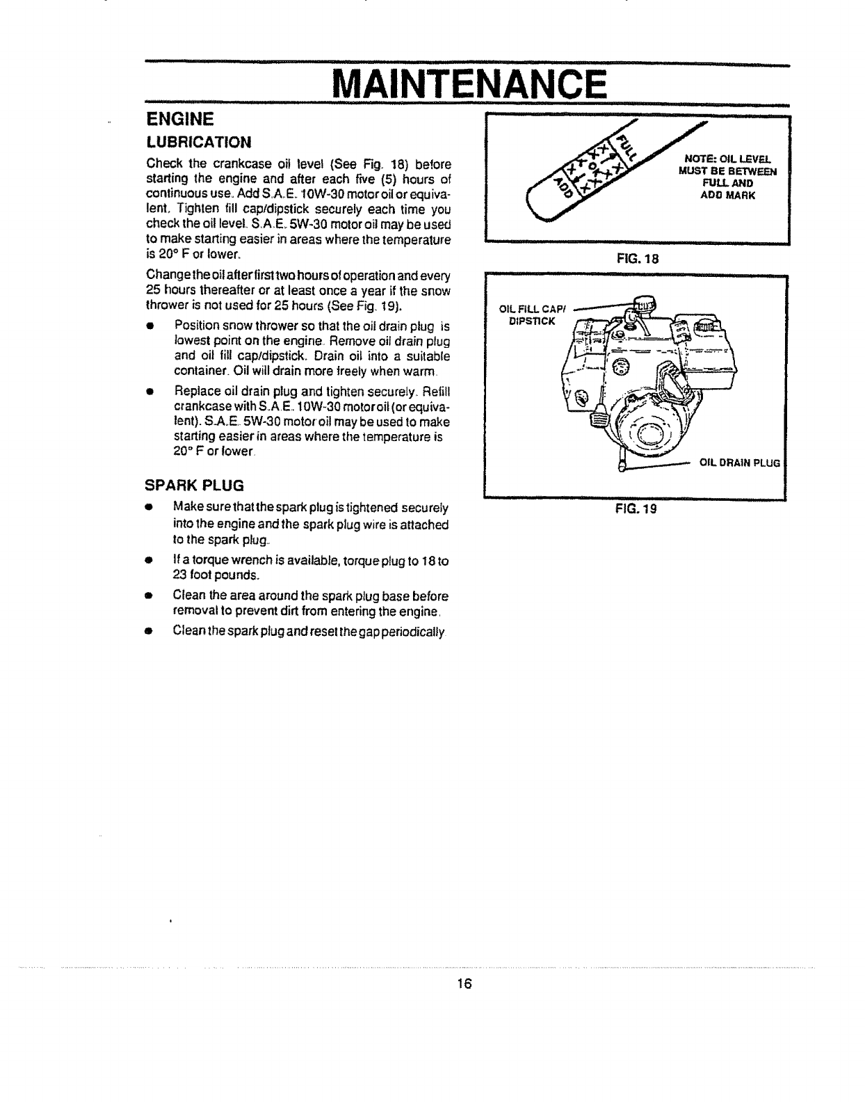
Check the crankcase oil level (See Fig. 18) before
starting the engine and after each five (5) hours of
continuous use°Add S.A.E_10W-30 motoroil orequiva-
lenL Tighten fill capldipstick securely each time you
check theoil level SA,E_ 5W-30 motor oil may be used
to make starting easier in areas where the temperature
is 20° F or iower_
Changethe oil afterlirst two hours of operation and every
25 hours thereafter or at least once a year if the snow
thrower is not used for 25 hours (See Fig. 19).
•Position snow thrower so that the oil drain ptug is
lowest point on the engine. Remove oil drain plug
and oil fill captdipstick,. Drain oil into a suitable
container. Oil will drain more freely when warm,
• Replace oil drain plug and tighten securely,, Refill
crankcase with S_AE, i0W-30 motor oit (or equiva-
lent). S.A_E,.5W-30 motor oil may be used to make
starting easier in areas where the temperature is
20 ° F or Iower_
SPARK PLUG
•Make sure that the spark plug istightened securely
into the engine and the spark pJug wire is attached
to the spark plug_
•If atorque wrench is available, torque plug to 18 to
23 foot pounds.
•Clean the area around the spark plug base before
removal to prevent dirt from entering the engine,
OIL FILL CAP/
DIPS'lICK
i= u
FIG, 18
Hi,ill ]lw
ILl III I L I_I I'III I I I ..........
FIG. 19
• Clean thesparkplugand reset thegapperiodically
16
: ..... i,ii i,,ll_ i,,11 ,i i, _, Ii
.......$ ..... CE AND ADJUST TS
::: _ ,ll,lll,lll,l,i....... ii ,,
: ............... : .......... ,,,,,,,,,,i
CAUTION: ALWAYS DISCONNECT THE I
SPARK PLUG WIRE AND 'TIE BACK
AWAY FROM THE PLUG BEFORE MAK-
ING ANY ADJUSTMENTS OR REPAIRS.
iii .
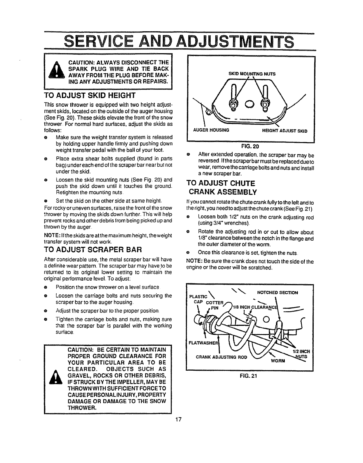
TO ADJUST SKID HEIGHT
This snow thrower is equipped withtwo height adjust-
merit skids, located on the outside of the augerhousing
(See Fig. 20)° These skids elevate the frontof the snow
thrower. For normal hard surfaces, adjust the skids as
follows:
eMake sure the weight transfer system is released
by holding upper handle firmlyand pushing down
weighttransfer pedal with the ball of your foot.
®Place extra shear bolts suppiied (found in parts
bag) under each end of the scraperbar near but not
under the skid..
e Loosen the skid mounling nuts (See Fig. 20) and
push the skid down until it touches the ground..
Retighten the mounting nuts.
®Set the skid on the other side at same heighL
For rocky or uneven surfaces, raise the front of the snow
thrower by moving the skids down furthers.This wifl help
prevent rocks and other debris from being picked up and
thrown by the auger
NOTE: if the skids are at the maximum height, the weight
transfer system will not work..
TO ADJUST SCRAPER BAR
After considerable use, the metal scraper bar will have
a detinite wear patternr The scraper bar may have to be
returned to its odginal lower setting to maintain the
original performance lever. To adjust:
oPosition the snow thrower on a level surface
oLoosen the carriage bolts and nuts securing the
scraper bar _othe auger housing.
oAdjust the scraper bar to the proper position.
®Tighten the carriage bolls and nuts, making sure
:hat the scraper bar is parallel with the working
surface.
CAUTION: BE CERTAIN TO MAINTAIN
PROPER GROUND CLEARANCE FOR
YOUR PARTICULAR AREA TO BE
CLEARED. OBJECTS SUCH AS
GRAVEL, ROCKS OR OTHER DEBRIS,
IF STRUCK BY THE IMPELLER, MAY BE
THROWN WITH SUFFICIENT FORCE TO
CAUSE PERSONALINJU RY, PROPERTY
DAMAGE OR DAMAGE TO THE SNOW
THROWER.
SKID MOUNTING NUTS
AUGER HOUSING HEIGH3 r ADJUST SKiD
0
i
FIG. 20 i,l,,lll,i ,,,
Afler extended operation_the scraper bar may be
reversed ifthe scraperbar mustbe replaceddueto
wear, removethe carriage botts and nutsandinstall
anew scraper bar.
TO ADJUST CHUTE
CRANK ASSEMBLY
tf you cannot rotate the chute crank fully to the left and to
the right,you need to adjust the chute crank (See Fig. 21)
eLoosen both 1t2" nuts on the crank adjusting rod
(using 3/4" wrenches).
eRotate the adjusting rod in or out to allow about
1/8" clearance between the notch inthe flange and
the ouler diameter of the worm..
e Once this clearance is set, tighten the nuts
NOTE: Be sure the crank does not touch the side of the
engine or the cover will be scratched°
PLASTIC
CAP COTTER/-'_.
NOTCHED SECTION
FIG. 21
17
,S...........
TO ADJUST THE CLUTCH CONTROL
CABLES
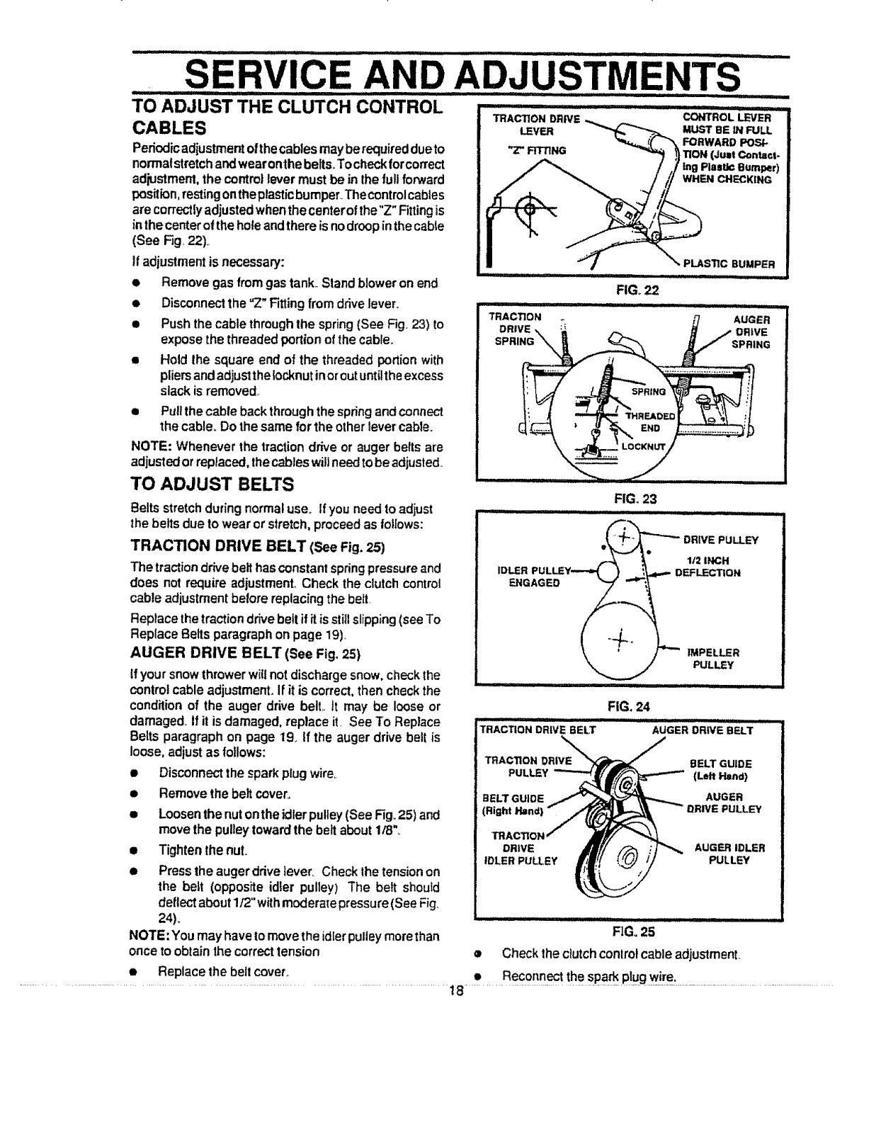
Pedodicadjustmentofthecablesmayberequireddueto
non'natstretchandwearonthe belts Tocheckforcorrect
adjustment, the controllever mustbe inIhe fullforward
position,restingontheplasticbumper+Thecontrolcables
are correctlyadjustedwhenthecenterofthe"Z"Fittingis
inthe centerofthe holeandthere is nodroopinthecable
(See Fig, 22),,
If adjustmentis necessary:
• Removegas fromgas tank+Standblower on end
eDisconnect the "Z" Fitting from drive lever.
•Push the cablethrough the spring (See Fig+23) to
expose the threaded portion of the cable+
•Hold the square end of the threaded portion with
pliers andadjust the Iocknutinor outuntilthe excess
slack is removed,,
ePull the cable back through the springand connect
the cable. Do the same for the other levercabte+
NOTE: Whenever the tractiondrive or auger beltsare
adjusted orreplaced, thecableswillneedtobe adjusted.
TO ADJUST BELTS
Beltsstretch during normal use+ If you needto adjust
the belts due to wear or stretch, proceed as follows:
TRACTION DRIVE BELT (See Fig. 25)
The traction drivebelt has constantspringpressure and
does not require adjustment,, Check the clutch control
cable adjustment before replacing the belt
Replacethe traction drive beltif it+sstillslipping (see To
Replace Beltsparagraph on page 19).
AUGER DRIVE BELT (See Fig. 25)
Ifyour snowthrowerwillnot dischargesnow,checkthe
controlcable adjustment+if it is correct,thencheckthe
conditionof the auger drive bell tt may be loose or
damaged+If it is damaged,replace it. See To Replace
Beltsparagraphon page 19+If the auger drive belt is
loose,adjustas follows:
• Disconnectthe sparkplugwire.
Removethe beltcover_e
oLoosen the nut onthe idler pulley(See Fig+25)and
movethe pulleytowardthe belt about1/8",,
• Tighten the nut.
•Press the auger drive tever_ Check the tensionon
the belt (opposite idler pulley) The belt should
deflect about 1/2" withmoderate pressure(See Fig+
24)+
NOTE: You may have tomove the idlerpulley morethan
once to obtain the correct tension
e Replace the belt cover.
: IIIIIIII iiii iiiii ,111 II iiii LL LI3UIL III1' ' iiiiiii ii IIIII I,i
E AND ADJUSTMENTS
............. _ II IIIII iiii1,1,11111 ii '1 I
i ................. ,i II ..........................
CONTROL LEVER
MUST BE IN FULL
FORWARD POS_.
TION (Ju=t Contact.
lng Plastic Bumper)
WHEN CHECKING
TRACTION DRIVE _
LEVER _"_..,___?.
"Z" FITTING
_'_ PLASTIC BUMPER
TRACTION
DRIVE
FIG+22
FIG. 23
-- ........................... iiiiii i II
. DFIIVE PULLEY
_I12 INCH
ID_R PULLEY---_ } .__',_4.,_ DEFLEC33ON
\'/---i.PeLLER
PULLEY
iiiij/ :,, _ _,,: _: .........
FIG. 24
............. i ...........
TRACTIO.Drove.ELT ......... ,dGE. R+VEB .T
TRACTION DRWE BELT GUIDE
PULLEY (Left Hand)
BELT GUIDE AUGER
(Right Hind) PULLEY
DRIVE AUGER IDLER
IDLER PULLEY PULLEY
FIG+25
•Check the clutchcontrol cableadjustmenL
•Reconnect the spad_plugwire.
i1,,,,i..... ii iiii,
,.SERVICE AND
TO REPLACE BELTS
The drive belts on this snow thrower are o! special
construction and should be replaced with original
equipment belts available from your nearest SEARS
Store or Service Center_
You will need the assistanceof a second person while
replacing the belts°
Drain the gasoline fromthe fueltankby removing the fuel
line., Drain the gas and reinstall fuel line,,
AUGER DRIVE BELT
If your snow throwerwiltnotdischarge snow, and the
auger drive belt isdamaged, replace it as to!lows:
®Disconnect the sparkplugwire.
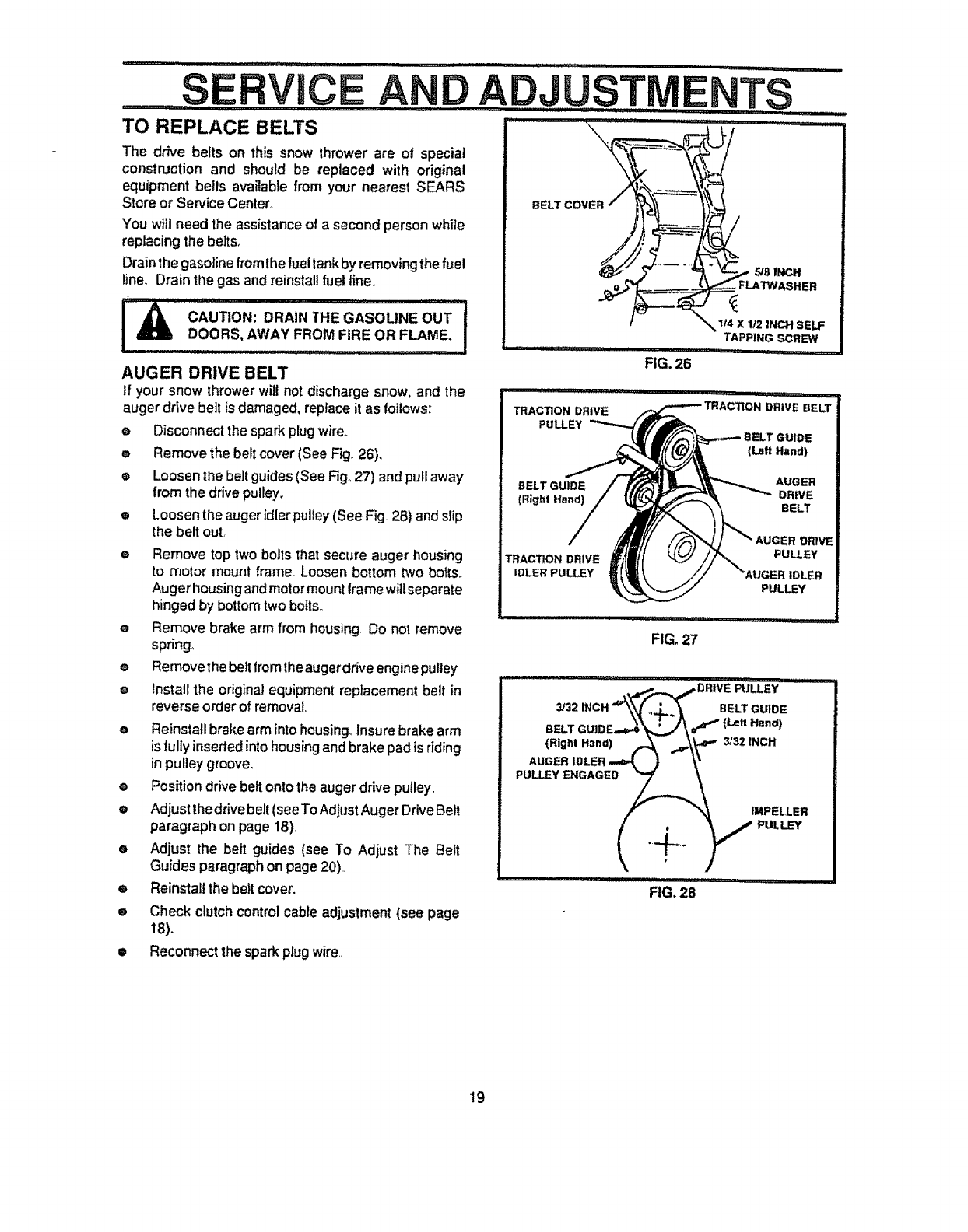
oRemove the beltcover(See Fig,,26).
® Loosenthe belt guides (SeeFig°27) and pullaway
from the drivepulley.
eLoosen the auger idler pulley(See Fig. 28)andslip
the belt out.,
e Remove toptwo bolls that secureauger housing
to motor mount frame. Loosenbottom two bolts.,
Auger housing andmotormountIramewillseparate
hinged by bottom two bolts.
eRemove brake arm from housing, Do not remove
spdng,
eRemove the belt fromthe augerdrive engine pulley
eInstallthe original equipmentreplacement bell in
reverse order of removal,
e Reinstall brake arm intohousing,,Insure brake arm
isfullyinsertedinto housingand brake pad is riding
inpulley groove°
Position drive belt onto the auger drive putley,
Adjust thedr_vebelt (seeTo AdjustAuger Drive Belt
paragraph on page 18),,
Adjust the belt guides (see To Adjust The Belt
Guides paragraphon page 20)+
0
0
0
0
(Right Hand)
TRACTION DRIVE
IDLER PULLEY
_32
{Righ! Hand)
AUGER
PULLEY ENGAGED
O
FIG, 27
Reinstallthe beltcover.
Check clutch control cable adjustment (see page
18)+
,,i,, iii ,lirai,,,,11,
FIG. 28
GUIDE
(Lalt Hand)
AUGER
DRIVE
BELT
:R DRIVE
PULLEY
PULLEY
!11' ll_j II I
BELT GUIDE
Hand)
3/32 INCH
IMPELLER
PUL L_Y
•Reconnect the spark plug wire,,
19
SERVICE AN ,.,DJUSTMENTS
ijj ii I1' ,111111 :: I'J ..... I
TRACTION DRIVE BELT TO ADJUST THE FRICTION WHEEL
If your snow throwerwiltnot move forward, check the
tractiondrive belt for wear.tfthe traction drivebelt needs
to be replaced,proceed as follows:
•Disconnect the sparkplugwire.
Remove the beltcover(See Fig.26).
Loosenbeltguides (SeeFig..27) andpullbeltguides
away from the enginedrivepulley..
Loosennutonaugeridler andpullaugeridlerpulley
away from bell
Remove auger drivebelt fromengine pulley.
Pull drive belt idler pulley away from drivebelt
Remove drive belt..
e
o
e
o
e
i
e
e
e
e
e
e
TO
Positionnew drive beft ontotractionpulley.
Pull idler puUeyaway from belt, ailowingbelt to be
positionedonto enginepulley
Release idlerpulley Ensureidlerpulleyis properly
engaged withbelt.
Adjustbelt guides(see To Adjust The BeltGuides
paragraphbelow).
Reinstallthe beltcover..
Reconnect the spark plug wire.
ADJUST THE BELT GUIDES
After you replace a track or auger drive belt, you need to
adjust one or both of the belt guides. Proceed as follows:
e Disconnect the spark p_ug wirer
• Remove the belt cover (See Fig 26)
• Engage the auger drive clutch lever_
• Measure the distance between the belt guides and
the belt (See Fig. 28)..The distance should be 3/32"
for each guide_
• If adjustment is necessary, loosen the belt guide
mounting bolts. Move the belt guides to the correct
position. Tighten the mounting bolts
eReinstall the belt cover..
• Reconnect the spark plug wire.
- .............../, .......
LOOSEN BOLT:_ :
i
REMOVE BOLT
OTTOM PANEL
li I BOTTOM PANEL
,,-.-- LOOSEN BOLT
If the snow thrower will not move forward, youneed to
checkthe trackdrivebelt,the tractiondrivecableorthe
frictionwheel,Ifthefriction wheelisdamaged;itwillneed
to be replaced. See the To Replace FrictionWheel
paragraphon page 21..If the friction wheel is notworn.
checkthe adjustment, as follows:
e Disconnect the spark plug wire,
•Drain the gasoline from the gas tank.
• Stand snow thrower on the auger housing end.
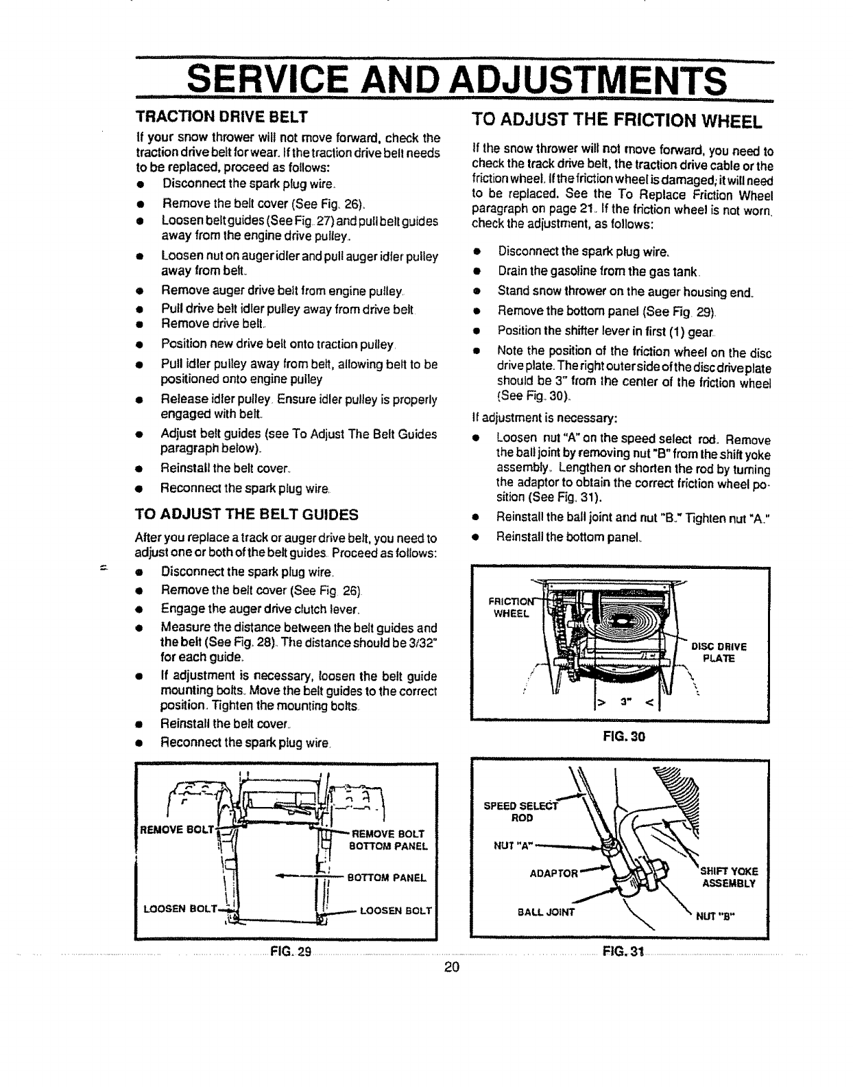
• Remove the bottom panel (See Fig. 29)
•Position the shifter lever in first (1) gear.
•Note the position of the friction wheel on the disc
drive plate. The right outer side of the disc drive plate
should be 3" from the center of the friction wheel
(See Fig,.30).
if adjustment is necessary:
•Loosen nut "A"on the speed select rod.. Remove
the ball joint by removing nut "B" from the shift yoke
assembly_ Lengthen or shorten the rod by turning
the adaptor to obtain the correct friction wheel po.
sition (See Fig, 31),
• Reinstall the ball joint and nut "Bo" Tighten nut "A."
• Reinstall the bottom panel
WHEEL
/
/
SPEED SELECT
ROD
ADAPTOI YOKE
ASSEMBLY
8ALL JOINT _NUT "B"
.......................FIG, 29 ......................................................................................................................................FlG.31 .................................................................................
2O
SERVICE ................................................................ADJUSTME TS
,lira L
I t ' "_"L
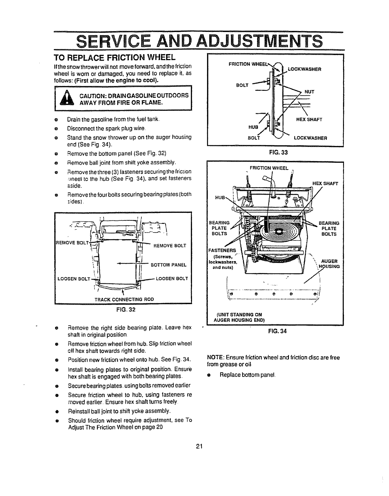
TO REPLACE FRICTION WHEEL
t!thesnowthrowerwillnot move forward, andthe friction
wheel is worn or damaged, you need to replace it,as
follows: (First allow the engine to cool).
ti,tt ,i,ii,t, ttttti,t t ,t _tt it ,t,t,,ttt,_
I,_ CAUTION: DRAINGASOMNE OUTDOORS I
AWAY FROM FIRE OR FLAME. i
eDrain the gasoline from the fuel tank,.
eDisconnect the spark plug wire
eStand the snow thrower up on the auger housing
end (See Fig. 34),,
oRemove the bottom panel (See F3g.,32)
eRemove ball joint from shift yoke assembly.,
o._emove the three (3) fasteners securing the friction
:Jneel to the hub (See Fig 34), and set fasteners
_side,_
® _emove the four bolts securing bearing plates (both
_ides],
EMOVEBOLT
LOOSEN BOLT -,,_
e'_
I
,_ REMOVE BOLT
lit
....... ..........._ LOOSEN BOLT
TRACK CONNECTING ROD
FIG, 32
•_emot,e fhe right side bearing plate.. Leave hex
shaft in originalposition.
eRemove friction wheel from hub.,Slip friction wheel
offhex shaft towards right sfde_
®Position new friction wheel onto hub._See Fig.34.
• Installbearing plates to original position.,Ensure
hex shaft is engaged with both bearing plates.
eSecure bearing plates, using boils removedearlier
•Secure friction wheel to hub, using fasteners re
moved earlier, Ensure hex shaft turns freely.
FRICTION WHEEL,,
BOLT
_H LOCKWASHER
T
FIG. 33
i,,i....
FRICTION WHEEL
HEX SHAFT
BEARING
PLATE
BOLTS
BEARING
PLATE
BOLTS
FASTENERS
(Screws_, '"" '
Iockwashers,
and nuls)
\;, AUGER
tJSING
(UNIT STANDING ON
AUGER HOUSING END)
FIG. 34
NOTE: Ensure friction wheelandfriction disc are free
from greaseoroil
•Replace bottom panel,
•Reinstall ball joint to shift yoke assembly,,
•Should friction wheel require adjustment, see To
Adjust The Friction Wheel on page 20
2!
.........SERVICE AND ADJUSTMENTS ......
.............. i ii ......... .............. iii/1_1'1'__,
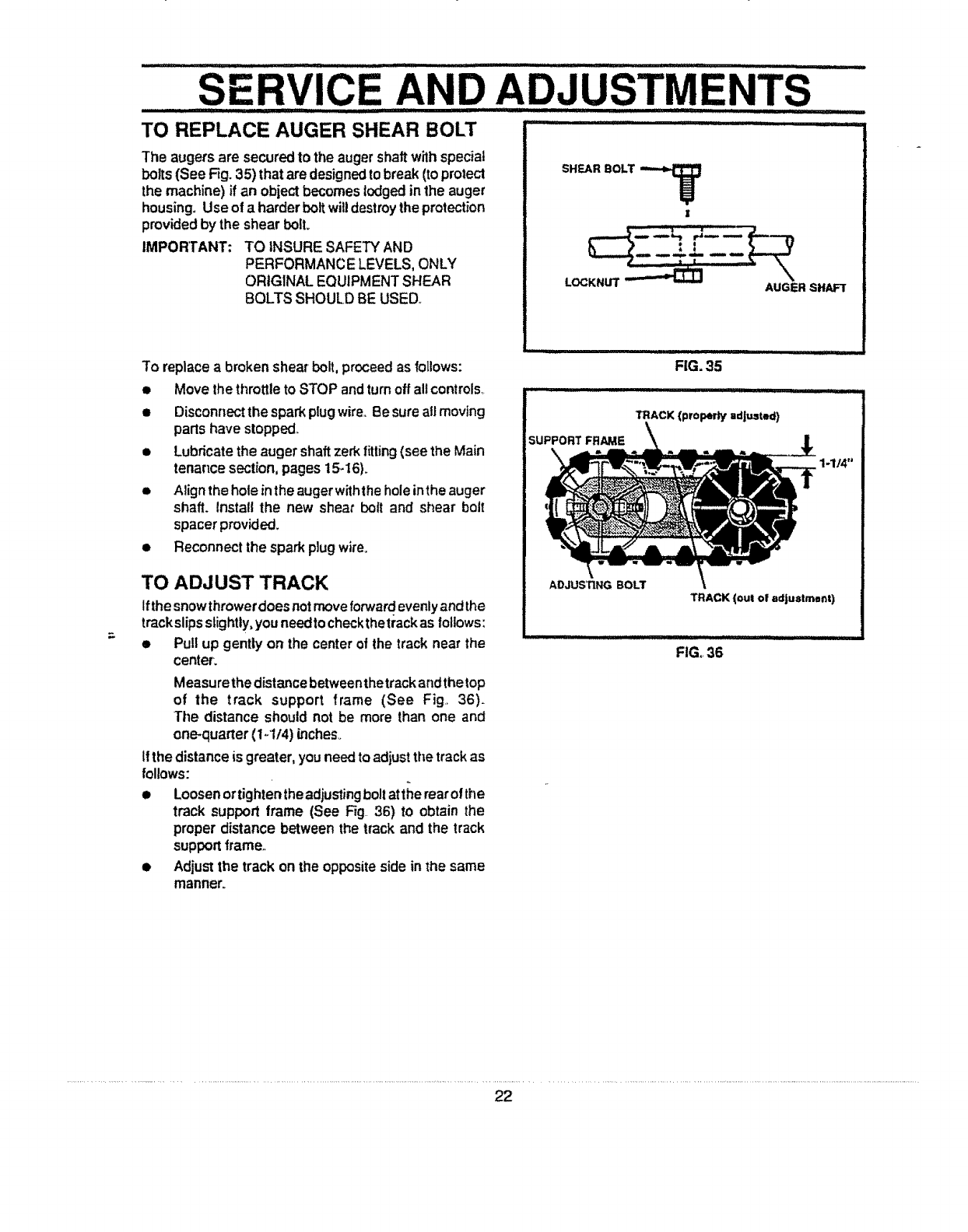
TO REPLACE AUGER SHEAR BOLT "'":'
The augers are securedto the auger shaftwithspecial
bolts (See Fig.35) thatare designedto break(toprotect
the machine) if an obiectbecomeslodged in the auger
housing. Use of a harderbolt wiUdestroytheprotection
providedby the shear bolt.
IMPORTANT: TO iNSURE SAFETY AND
PERFORMANCE LEVELS,ONLY
ORIGINAL EQUIPMENT SHEAR
BOLTS SHOULD BE USED.
SHEAR BOLT
AUGER SHAFT
To replace a broken shear bolt, proceedas follows:
• Movethe throttleto STOP andturnoffallcontrols,.
• Disconnectthesparkplugwire..Be sure all moving
partshave stopped,
• Lubricatethe auger shaftzerkfitting (see the Main
tenance section,pages 15-16).
•Align the holeinthe auger withthehole inthe auger
shaft. Install the new shear boll and shear boll
spacer provided.
• Reconnect the spark plug wire.
TO ADJUST TRACK
Ifthesnowthrowerdoesnotmoveforward evenlyand the
trackslipsslightly,youneedtocheckthetrackas follows:
• Pull up gently on the centerof the track near the
center.
Measurethedistancebetweenthetrackandthetop
of the track support frame (See Fig.. 36).
The distance should not be more than one and
one-quarter(1-1t4) inches..
if the distanceis greater,youneedto adjust the trackas
follows:
• Loosenortighlentheadjustingbolt atthe rearof the
track support frame (See Fig 36) to obtain the
proper distance betweenthe track and the track
supportframe,.
• Adjustthe track onthe oppositesidein the same
manner.
SUPPORT FRAME
FIG. 35
'TRACK (property adjusted)
1-1/4"
TRACK (out of adjustmant)
FIG,.36
22
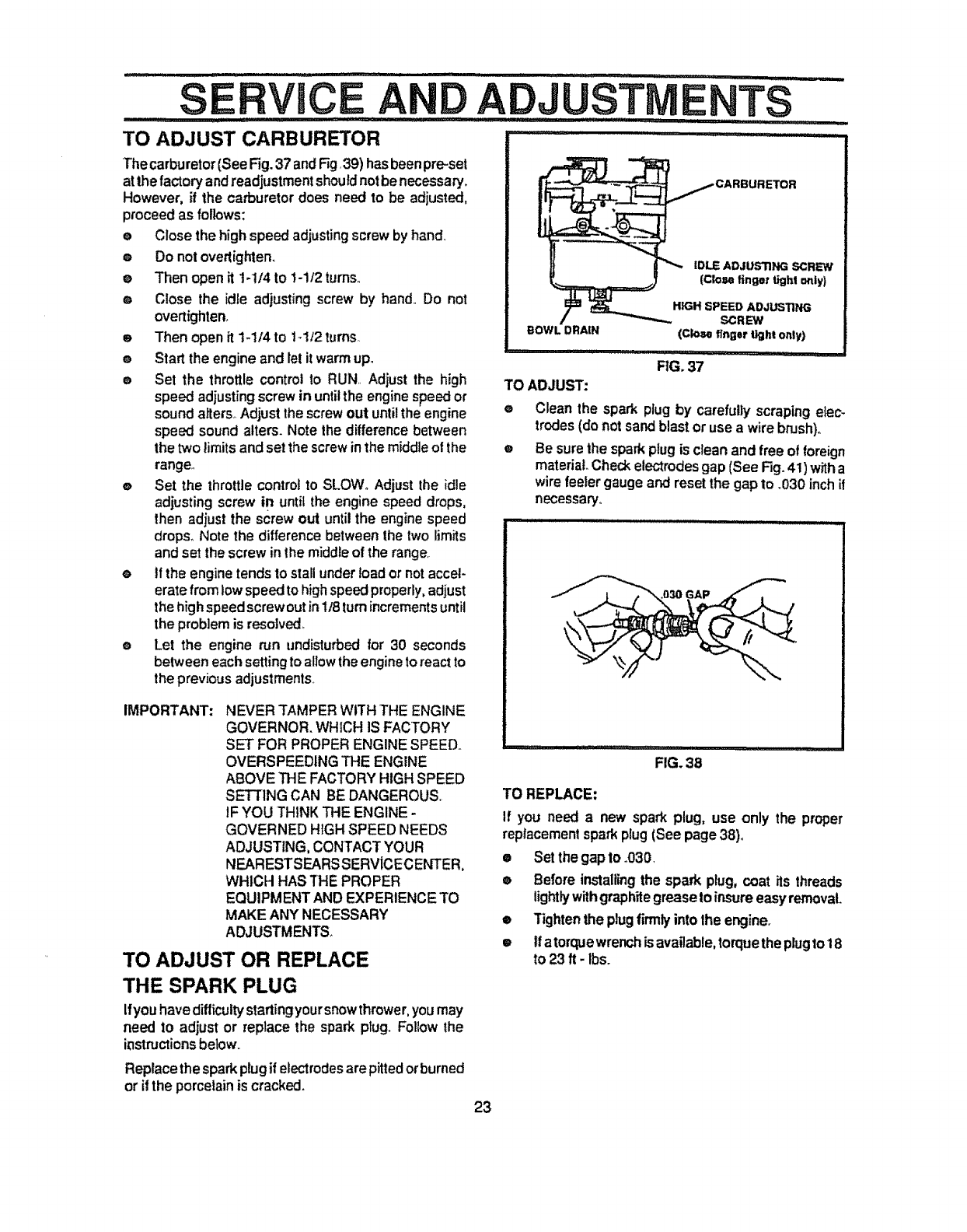
TO ADJUST CARBURETOR
The carburetor(See Fig.37andRg,39) hasbeenpre-set
atthe factoryandreadjustmentshouldnot benecessary.
However, if the carburetordoes need to be adjusted,
proceed as follows:
e Close the high speed adjusting screw by hand.,
®Do nol overtighten.
e Then open it t-1/4 to 1-1t2turns,,
® Close the idle adjusting screw by hand,,Do not
overtighten,
e Then open it 1-1/4to tdt2tums,,
® Start the engineand le!it warmupo
eSet the throttle controlto RUN,, Adjust the high
speed adjustingscrew in until the enginespeed or
SE CE A ADJUST TS
IDLE ADJUSTING SCREW"
(Close finger tight o_tly)
HIGH SPEED ADJUSTING
SCREW
BOWL DRAIN (Close finger light only)
FIG. 37
TO ADJUST:
sound aiters_ Adjust the screw out until the engine
speed sound alters. Note the difference between
the two limits and set the screw in the middle ol the
range,,
eSet the throttle control to SLOW,, Adjust the idle
adjusting screw in until the engine speed drops,
then adjust the screw out until the engine speed
drops. Note the difference between the two limits
and set the screw in the middle of the range.
eif the engine tends to stall under load or not accel-
erate from low speed to high speed properly, adjust
the high speed screw out in1/8 turn increments until
the problem is resolved
eLet the engine run undisturbed for 30 seconds
between each setting to allow the engine to react to
the previous adjustments,
IMPORTANT: NEVER TAMPER WITH THE ENGINE
GOVERNOR. WHICH IS FACTORY
SET FOR PROPER ENGINE SPEED.,
OVERSPEEDING THE ENGINE
ABOVE THE FACTORY HIGH SPEED
o
@
Clean the spark plug by carefullyscrapingelec-
trodes(do not sand blast or use a wirebrush).
Be sure the spark plug is clean and free of foreign
material Check electrodes gap (See Fig. 41)with a
wire feelergauge and reset the gap to .030 inch if
necessary°
.:,,,i ,11,,, I i i
FIG. 38
SETTING CAN BE DANGEROUS.
IF YOU THINK THE ENGINE -
GOVERNED HIGH SPEED NEEDS
ADJUSTING, CONTACT YOUR
NEARESTSEARSSERVICECENTER,
WHICH HAS THE PROPER
EQUIPMENT AND EXPERIENCE TO
MAKE ANY NECESSARY
ADJUSTMENT&
TO ADJUST OR REPLACE
THE SPARK PLUG
Ifyouhave difficulty startingyoursnowthrower,you may
need to adjust or replace the spark plug. Follow the
i_structions below,,
Replacethe spark plug if electrodesare pittedorburned
orit the porcelain is cracked.
TO REPLACE:
If you need a new spark plug, use only the proper
replacementspark plug (See page 38),,
• Set the gap to .030,
® Before installingthe spark plug, coat its threads
lightlywithgraphitegreaseto insure easyremoval
e Tightenthe plug firmlyinto the engine.
etfatorquewrenchisavailable,torquetheplugtot 8
to 23 ft- lbs.
23
......................... STORAG: 111111'11111 111111111 111 ' ........................ IIIII IIIIIIII!L
I'111"! IXILIII II II I'111111 .............. :....... lj I'[11111 II ..... iii, I
............ i, ,i,i ii......... IU U
CAUTION: NEVER STOREYOUR SNOW
"_HROWER INDOORS OR IN AN EN-
CLOSED, POORLY VENTILATED AREA
IF GASOLINE REMAINS IN THE TANK. FUMES
MAY REACH AN OPEN FLAME, SPARK OR PI-
LOTLIGHTFROM A FURNACE,WATER HEATER,
CLOTHES DRYER, CIGARETTE, ETC.
,11111 ............. :: ::: iiiiIll I' II ll'l' J" I II"
To preventenginedamage (if snowthroweris notused
formorethan30 days) follow the stepsbelow.
ENGINE STORAGE
Gasoline must be removed or treated to prevent gum
deposits from forming in the tank, filter, hose, and
carburetor during storage. Also during storage, al-
cohol blended gasoline that uses ethanol or metha-
nol (sometimes called gasohol) attractswater°It acts
on the gasoline to form acids which damage the
engine.
@
I
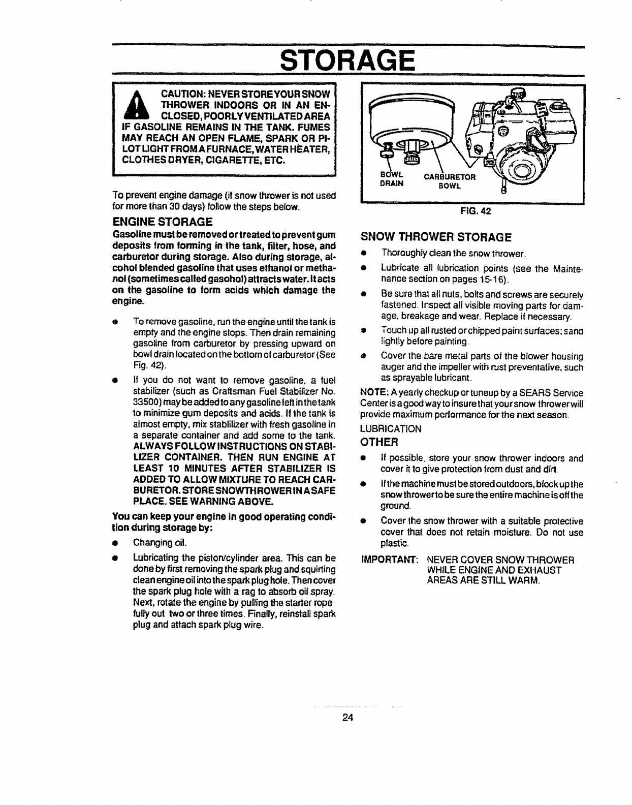
Toremovegasoline,runthe engineuntilthetank is
emptyandthe enginestops..Then drainremaining
gasolinefrom carburetorby pressingupwardon
bowldrain!ocatedon thebottomofcarburetor(See
Fig 42).
if you do not want to remove gasoline, afuel
stabilizer(such as Craftsman Fuel StabilizerNo..
33500)maybeaddedto anygasolineleftinthetank
to minimizegum depositsandacids_If the tank is
almostempty,mix stablilizerwithfresh gasolinein
aseparate containerand add some to the tank..
ALWAYS FOLLOW INSTRUCTIONS ON STABI-
LIZER CONTAINER. THEN RUN ENGINE AT
LEAST 10 MINUTES AFTER STABILIZER IS
ADDEDTO ALLOW MIXTURE TO REACH CAR-
BURETOR.STORESNOWTHROWER INASAFE
PLACE=SEE WARNING ABOVE.
You can keep your engine in good operating condi-
tion during storage by:
• Changingoilo
• Lubricatingthe piston/cylinderarea. This can be
doneby firstremovingthesparkplugand squirting
cleanengineoilintothesparkplughole.Thencover
the sparkplug holewitha rag to absorboilspray..
Next, rotatethe engineby pullingthe starterrope
fulPfout two orthreetimes. Finally,reinstallspark
plugand attachsparkplugwire.
DRAIN CARBURETOR
BOWL
FIG. 42
SNOW THROWER STORAGE
•Thoroughlycleanthe snow thrower.
• LubricateaB lubrication points (see the Mainte-
nancesection onpages 15-16).
• Be surethat ai[ nuts, boltsandscrews are securely
fastened..Inspectall visiblemovingpartsfordam-
age,breakage andwear. Replace if necessary..
=Touchupallrustedorchippedpaintsurfaces;sane
_ightlybeforepainting.
• Cover the bare metal partsof the blower'housing
auger and[he impellerwithrustprevenlative,such
as sprayablelubricant.
NOTE: Ayearly checkuportuneupby aSEARS Service
Centerisagoodwaytoinsurethatyoursnowthrowerwill
providemaximum performanceforthe next season.
LUBRICATION
OTHER
•If possible, storeyour snow throwerindoorsand
coverffto give protection fromdust and dirt.
• tfthemachinemust bestoredoutdoors,b!ock upthe
snowthrowertobesuretheentiremachineis offthe
ground.
• Cover Ihe snowthrowerwithasuitableprotective
cover that does not retain moislure Do not use
plastk:.
IMPORTANT: NEVER COVER SNOW THROWER
WHILE ENGINE AND EXHAUST
AREASARE STILLWARM..
24
SERVICE i i ,,,ll,Ui,,
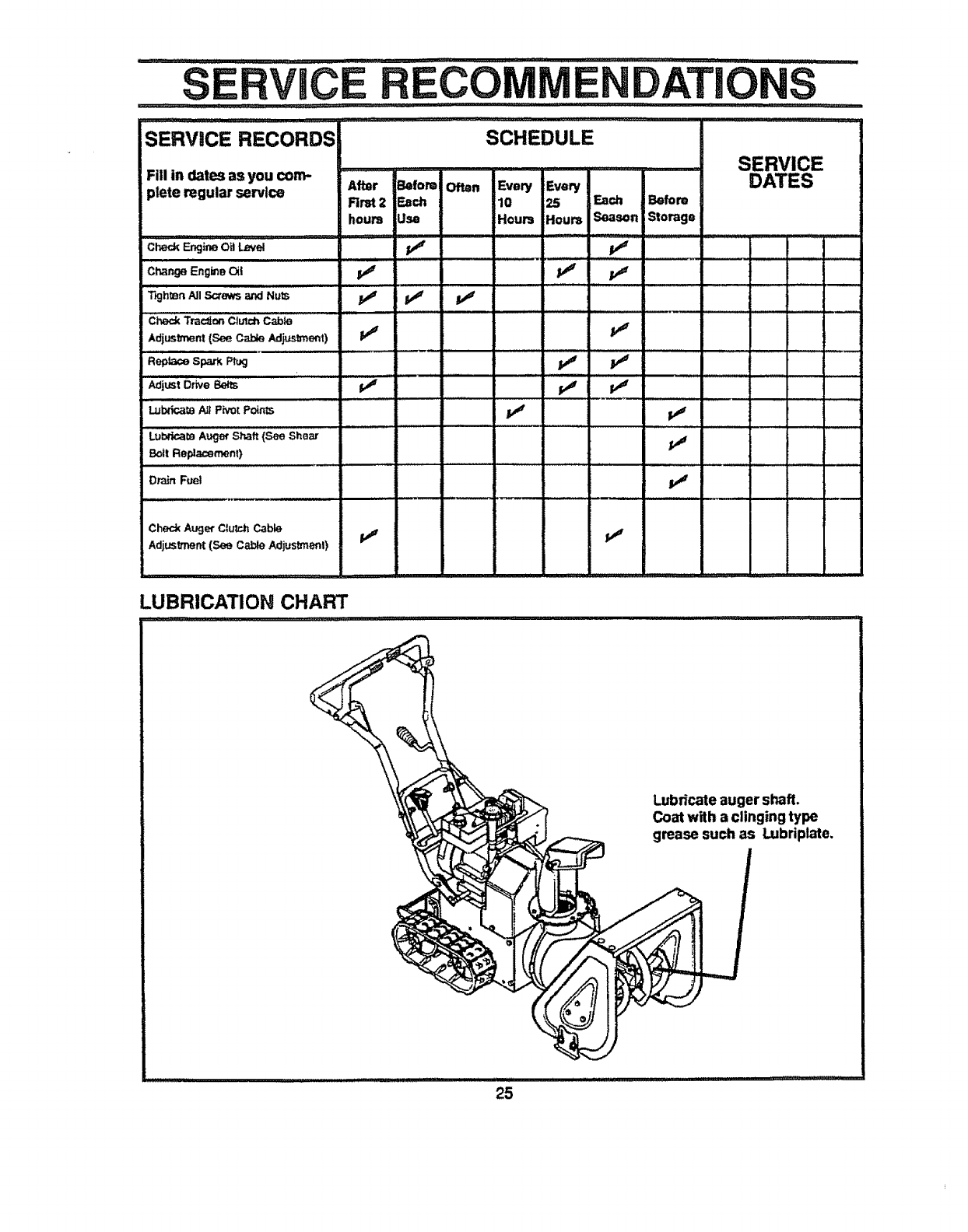
iSERVICE RECORDS SCHEDULE
Fill In dates as you co_
plete regular _l_
i=,l,i .......
Aftor Belomi Often Every Evew
Rrst 2 Each 10 25 _ch Before
hours Usa Hours Houm Season Storage
CheckF__j_ OaLave
Change _gme Oil 1_
IIu/ i i, ,,_, JJ ...........
T_jh_n All Screws _Nuts
SERVICE
DATES
ill
Check Aug_ Clu'c.hCabLe
Adj_nt (See Cable Adius_l )
LUBRICATION CHART
.............................. ,...r...,,.;;;, .....
_bfi_te auger shaft.
Coat with aclinging type
grease such as _briplate.
,,,lUll,, l ll'lmill' l l millll'lllll'l'll l UI'I'U'IIIIII::CCC:C::_
........TROUBLE SHOOTING POINTS ..............
, ,,,,,,,,,,,,,,,,,,,,I/l/Ull/lUI/ll/l/l/I ' I,I, Illl 'l II' l llll
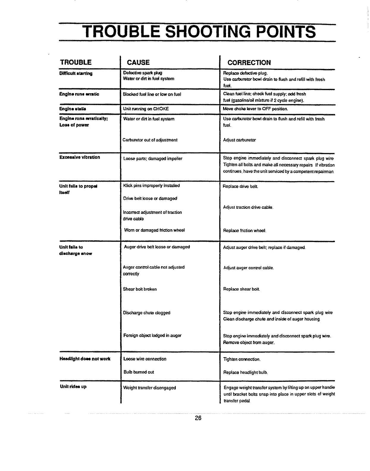
TROUBLE
Otlflcult=tBllng
Engine r_n_ =talk=
En=tne=IaUi
Engln=PJr.aerr=llc_mlly;
L=_ ofpower
Excessive vtbr=tlon
Unttfall=to propel
ite,e4r
Unit tfatiato
dlzcl_rge =now
CAUSE
Defectivespark#ug
Water or d'_ in fuel sys_m
Blo_d _e! lineorlowonfuel
Unitrunningon CHOKE
Water or dirtin fuel system
Carburetorouto! adjustment
Loosepa_.,s;damaged impairer
KlP..,kpins improperly instaJk_d
Dnva bett loose at damaged
incorrect adjustment of traction
drive cable
Worn or damaged tric_n whee!
Auger drive belt loose or damaged
Auger controlcable not adtusted
CORRECTION
J J llJIIIIII
Replace dafe==tiveplug.
Use ca_oumtorbowl drainto flush and refitlwithfresh
fuel.
Jiu,ii i _ • ,,lllll,i ,lli H,i i.................
fuel(gasoline/oil mixture if 2 cycleengine).
Move chek_ lever to OFF pos_don..
,,,,,,,,,,,,,,,,, ,,,,,,,,,, ,,, ,,,,, ,,,,,,,,,,,, ,, ,, ,,, ,,,, ,,
usec=_u,e=_bowldr_ _ _ushan_radii_th fresh
fuel
Adjustca_'buretor
IIIII IIIIIIIILIL IlL i I Ilmlll
Stop engine immediately and disconnectspark plug wire
Tightenatlbo!_ and make all necessaryrepairs if vibration
continues,havethe unitservicedby acompetentml_irman,
Replace d,6vebelL
Adiustt_ction drivec_le,
Rel_a,cef'dct_onwheel
iillllllllllllllllll i i i i iiiiiiiiiii i i i i ill Jli J III_iillilliill II I I I i i lililllllllll III L J
Adjustauger drivebelt; repla_ if damaged=
Adjustauger controlcable,,
con'ec_y
Shear boltbroken
Discharge chute dogged
Foreign objectlodged in auger
Replace shear boll
Stop engine imme_ately and cfsc_nnect spark plug wire
Ck_an disct_rge chute and i_side of auger housing
Stop engineimmoo_tely and disconnectspaskplugwire,,
Remove objectEarnauger.
!,baWighl doel nol work
Unit ride= up
Loosewimconnection
ButbI_.tmedout
: : IIIIIIIIIIIIIIIII I ii ii1_ ii i i ii iiiiii ii ii ii iiii L L I
Weight t_ansferdisengaged
Tighten connec_ort,,.
Replace headlightbulb.
ii Illlllll Illllll IIII li
Engageweight_ansfer systembylifting upon upperhand)e
un_i bracketbelts snap into p_ce in upper slotsof weight
transferpedaJ
26

iNOTES
i i i,iii, iii, i,_11 i i .... ii I'H'I _ _ :
27
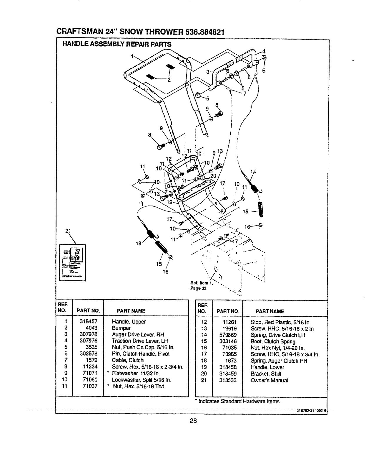
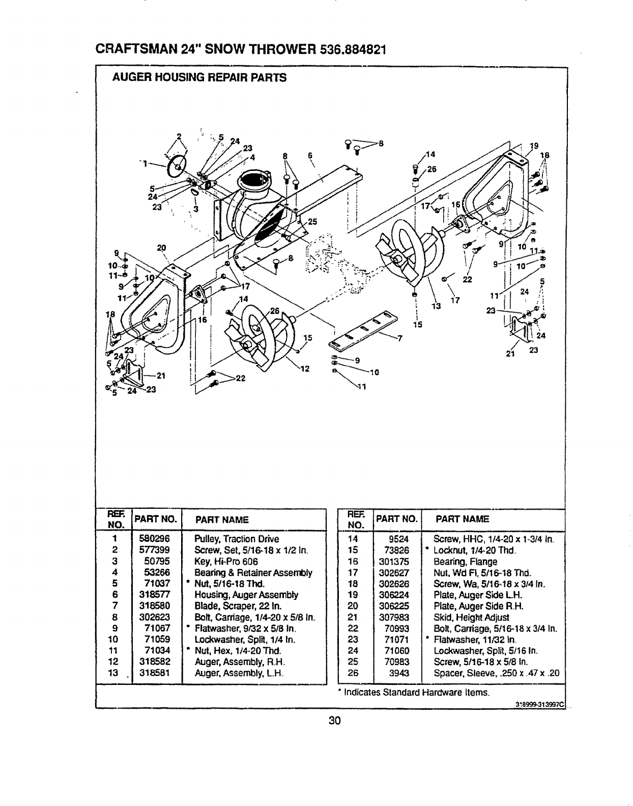
CRAFTSMAN 24" SNOW THROWER 536.884821
HANDLE ASSEMBLY REPAIR PARTS
?
9
\
12
1!
\
21
REF.
NO.
1 318457
24049
3 307978
4 307976
5 3535
6 302578
7 1579
8 11234
9 71071
10 71060
11 71037
PART NOD PART NAME
Handte, Upper
Bumper
Auger Drive Lever, RH
Traction Drive Lever, LH
Nut, Push On Cap, 5/16 In.
Pin, Clutchftandle, Pivot
Cable, Clutch
Screw, Hex. 5/16-18 x 2-3/4 In.
* Ratwasher. 11/32 in..
Lockwasher` Split 5/16 In..
" Nut, Hex. 5/16-18 TI_.
I
5
PARTNAME
Slop, Red Plastic, 5t16 In.
Screw. HHC, 5/16-18 x 2In
Spring, Drive C_utch LH
Boot, Clutch Spdng
Nut, Hex Nyt, 11420 in
Screw, HHC, 5116-18 x 3/4 In.
Spdng, Auger Clutch RH
Hand{e. Lower
Bra_et, Shift
O',vnet's Manua}
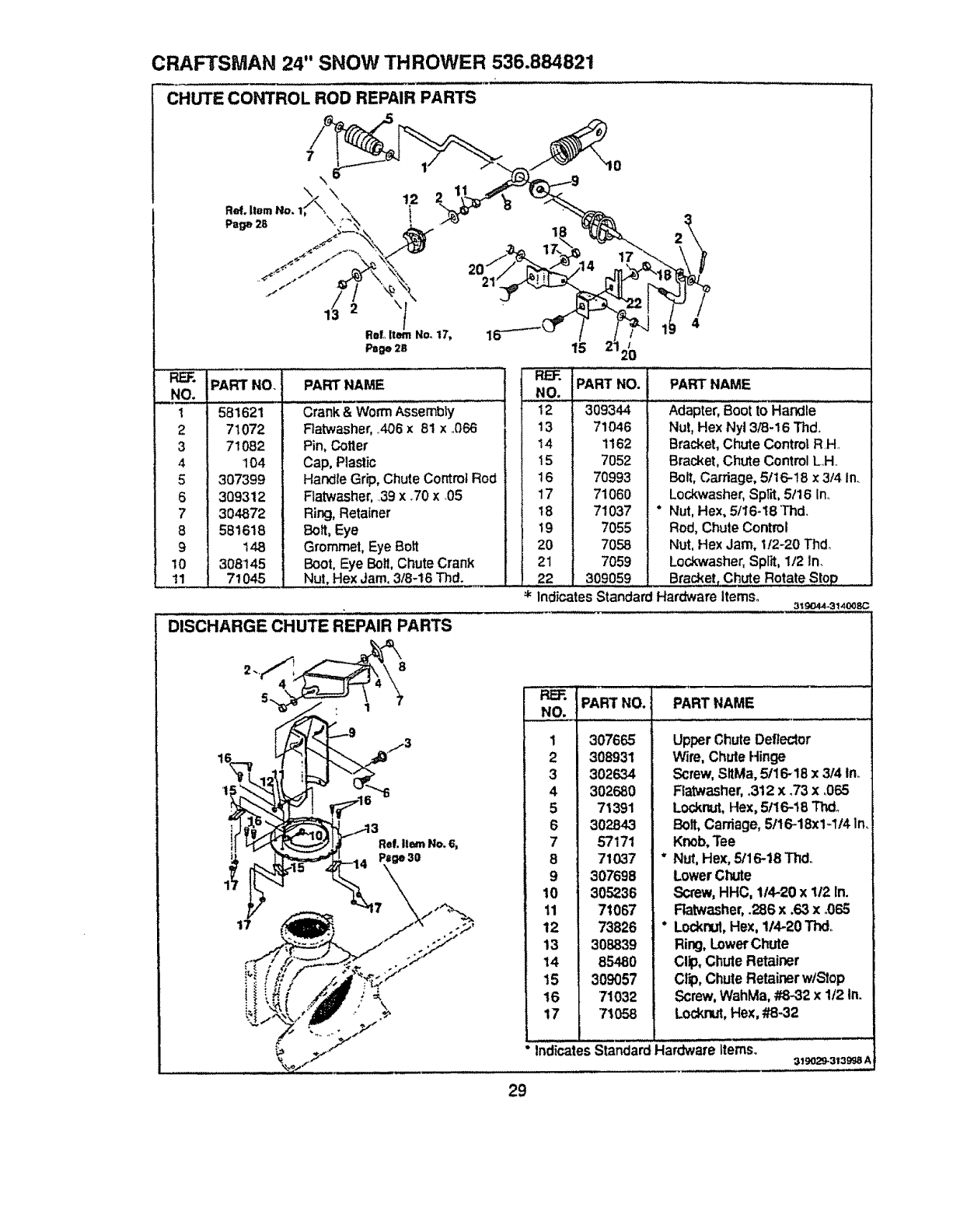
CRAFTSMAN 24" SNOW THROWER 536.884821
CHUTE CONTROL ROD REPAIR PARTS
Ret. Ilem . \ ,, .|,
RE_. ¸ I
NO. !
t
2
3
4
5
6
7
8
9
10
11
PART NO. PART NAME
581621
71072
71082
104
307399
309312
304872
581618
148
308145
7t 045
Crank& WormAssembly
Ratwasher,406 x 81 x .066
Pin,Cotter
Cap, Plastic
Handle Grip,ChuteControlRod
Flatwasher,.39 x .70 x.05
Ring,Retainer
Bolt, Eye
Grommet, Eye Bott
Boot, Eye Boll, ChuteCrank
Nut, HexJam. 3/8-18 Thd.
DISCHARGE CHUTE REPAIR PARTS
2.,t_4 _'__ 8
17
PART NO. PART NAME
NO.
12 309344 Adapter,Boot to Handle
13 71046 Nut,Hex Nyl3/8-16 Thd.,
14 1162 Bracket,Chute ControlR H
15 7052 Bracket,Chute ControlLH
16 70993 Boll, Carriage,5/16-18 x3/4 In..
17 71060 Lockwasher,SpFd,5/16 In..
I8 71037 " Nut,Hex,5/16-18 Thd.
;19 7055 Rod, ChuteControl
i 20 7058 Nut, Hex Jam, 1!2-20 Thdo
i 21 7059 Lockwasher,Split, 112In,
! 22 309059 Bracket,Chute R0tate StOP
* Indicates Standard Hardware Items. 319044_14008C
REF. PART NO. PART NAME
NO.: ................................................................
1 307665
2 308931
3 302634
4 302680
571391
302843
57171
871037
9 307698
10 305236
11 71067
12 73826
13 308839
14 85480
15 309057
16 71032
17 71058
°Indicates
Upper ChuteDeflector
Wire,ChuteHinge
Screw,SitMa,5t16-18 x 314ln_
Flatwasher,.312 x.73 x ..065
Locknut,Hex, 5/I6-18 Thdo
Bolt, Carriage,5/16-18x1-114In.
Knob,Tee
Nut, Hex,5/16-18 Thd,.
LowerChute
Screw,HHC, 1/4-20 x 112In.
Ratwasher,.286 x.63 x.065
Locknut,Hex, 114-20Thd.
Ring,Lower Chute
Clip,ChuteRetainer
Clip, Chute Retainerw/Stop
Screw,WahMa,#8-32 x 1t2 In.
Locknut,Hex,#8-32
StandardHardwareItems. 319029-313998 A
29
CRAFTSMAN 24" SNOW THROWER 536.884821
AUGER HOUSING REPAIR PARTS
2_.r23
6
\//14
16
21 23
REF. PART NO.
NO.
1
2
3
4
5
6
7
8
9
10
11
12
13
580296
577399
5O795
53266
71037
318577
318580
302623
71067
71059
71034
318582
318581
PART' NAME
,,,,,,,,,,i,,,,,,,,,,, i,llJ
Pulley,Traction Drive
Screw, Set, 5/16-18 x 1/2 in,
Key, Hi-Pro 606
Bearing & Retainer Assembly
" Nut, 5116-18 "Thd°
Housing, Auger Assembly
Blade, Scraper, 22 In.
Bolt, Carriage, 114-20 x 5/8 Ino
" Flatwasher, 9/32 x 5/8 in.
Lockwasher, Split, 1/4 tn.
"Nut, Hex, 1/4-20Thdo
Auger, Assembly, RH
Auger, Assembly, LH
RE]. PART NAME
NO.
14
15
16
17
18
19
2O
21
22
23
24
25
26
"Indicates Standard Hardware ltems_
!.A ,01
9524
73826
301375
302627
302626
306224
3O6225
307983
70993
71071
71060
70983
3943
Screw, HHC, 1/4-20 xi-3/4 In.
*L.o_._nut,1/4-20Thd.
Beating, Flange
Nut,Wd R, 5116-18Thd.
Screw, Wa,5116,18x 3/4 In.
Plate,AugerSideLH.
Plate,AugerSide RH.
Skid, HeightAdjust
Bolt, Carriage,5t16-18x 314In.
"Ratwasher,11/32 in
Look'washer,Spilt,5t16 in.
Screw, 5f16-18x 5t8 In.
Spacer,Sleeve, .250 x.47 x20
3 ',8999,313997C
30
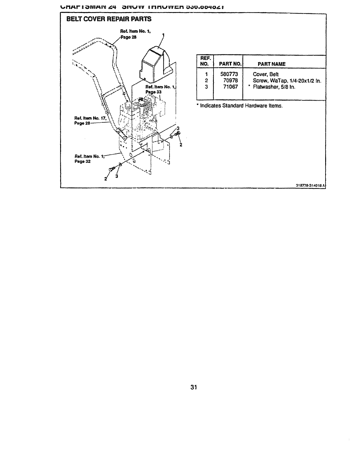
v_,_.rtJq,r- j;='_I'_F_,I_ ,_q. Oll_lrjvy i rtrtt=/vvlc;rt ;_,lu,oo_o,_. g
BELT COVER REPAIR PARTS
Ref.It_rnHOo
REF.
NO. PART NO. PART NAME
,,,uu,,, ..............
1 580773 Cover,Belt
2 70978 Screw, WaTap, 1/4-20xl/2 Ino
3 71067 * Flatwasher,518Ino
*IndicatesStandardHardwarettems_
31B778_31i4018 A
31
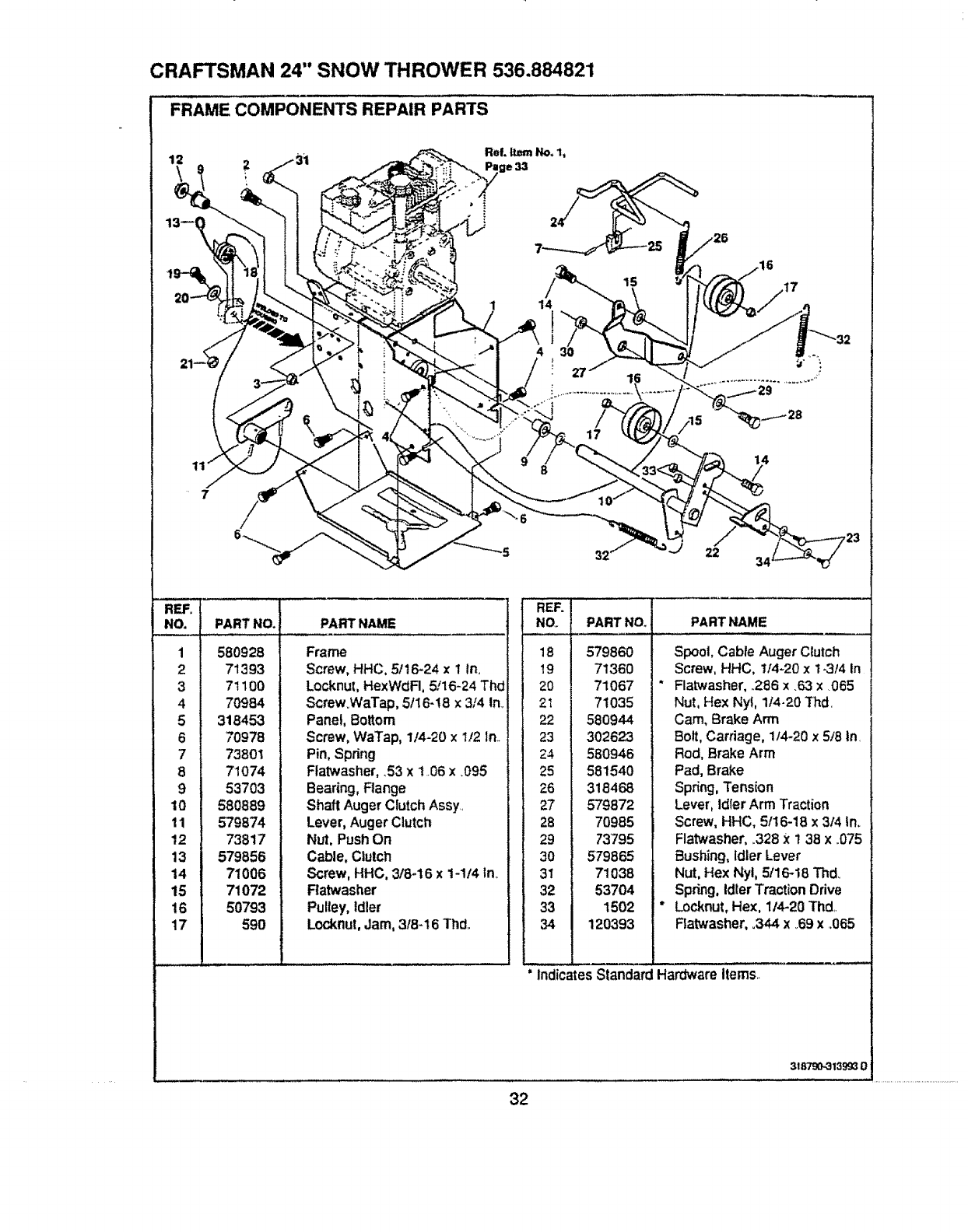
CRAFTSMAN 24" SNOW THROWER 536.884821
FRAME COMPONENTS REPAIR PARTS
15
14
4
27 1
17 /15
14
-5 32 22
REF.
NO.
1
2
6
7
8
9
10
11
12
13
14
15
16
17
PART NO.
580928
71393
71100
70984
318453
70978
73801
71074
53703
580889
579874
73817
579856
71006
71072
50793
590
PART NAME
Frame
Screw, HHC, 5116_24 x 1 In.,
Locknul, HexWdFI, 5!16-24 Thd
Screw.WaTap, 5/16-t8 x 3/4 In_
Panel, Bottom
Screw, WaTap, 1/4-20 x 1/2 In.
Pin, Spring
Ftatwasher, .53 x 1.06 x .095
Bearing, Flange
Shaft Auger Clutch Assy.
Lever, Auger Clutch
Nut, Push On
Cable, Clutch
Screw, HHC, 3/8-16 x 1-1/4 in..
Ratwasher
Pulley, Idler
Locknut, Jam, 3/8-16 Thd,.
REFo
NOo PART NO.
18 579860
19 71360
20 71067
21 71035
22 580944
23 302623
24 580946
25 581540
26 318468
27 579872
28 70985
29 73795
30 579865
31 71038
32 53704
33 1502
34 120393
PART NAME
Spool, Cable Auger C_utch
Screw, HHC, 1/4-20 x 1-3/4 In
" Flatwasher, .286 x .63 x 065
Nut, Hex Nyl, 1/4-20 Thd.
Cam, Brake Arm
Bolt, Carriage, 1t4-20 x 5/8 In.
Rod, Brake Arm
Pad, Brake
Spring, Tension
Lever, Idler Arm Traction
Screw, HHC, 5/16-18 x 3/'4 In.
Flat'washer, ,328 X 1 38 x ..075
Bushing, Idler Lever
Nut, Hex Nyl, 5/16-18 Thd_
Spdng, Idler Traction Drive
* Locknut, Hex, 1/4-20 Thd,.
Flatwasher, .344 x _69x .,065
'indicates Standard Hardware items..
32
3t 8790-313993 0
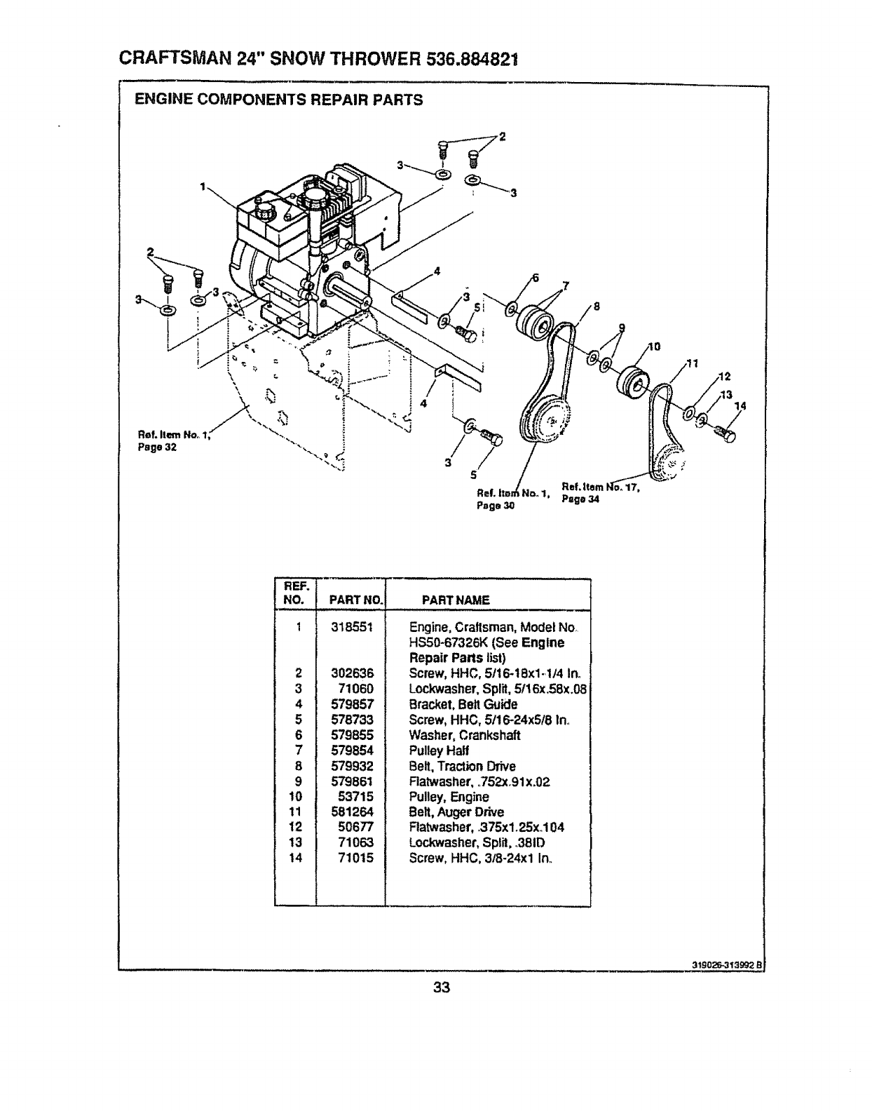
CRAFTSMAN 24" SNOW THROWER 536.884821
ENGINE COMPONENTS REPAIR PARTS
Ref. Item Noo
Page 32
\\
REF.
NO.
1
2
3
4
5
6
7
8
9
10
111
12 _
13
14
PART NO. PART NAME
318551
302636
71060
579857
578733
579855
579854
579932
579861
53715
581264
50677
71063
71015
Engine,Craftsman,ModelNo
HSS0*67326K(See Engine
Repair Paris list)
Screw,HHC, 51t6-18x1.114Inn
Loci(washer,Split,5116x.58x.08
Bracket,BeltGuide
Screw,HHC, 5/16-24x5/8 In.
Washer,Crankshaft
PulleyHalf
Belt, TractionDdve
Ratwasher,o752xr91x.02
Pulley,Engine
Belt,AugerDrive
Ftatwasher,375x1.25x 104
Lock_asher, Split,381D
Screw, HHC, 318-24xl In
33
3t g026.313992 B
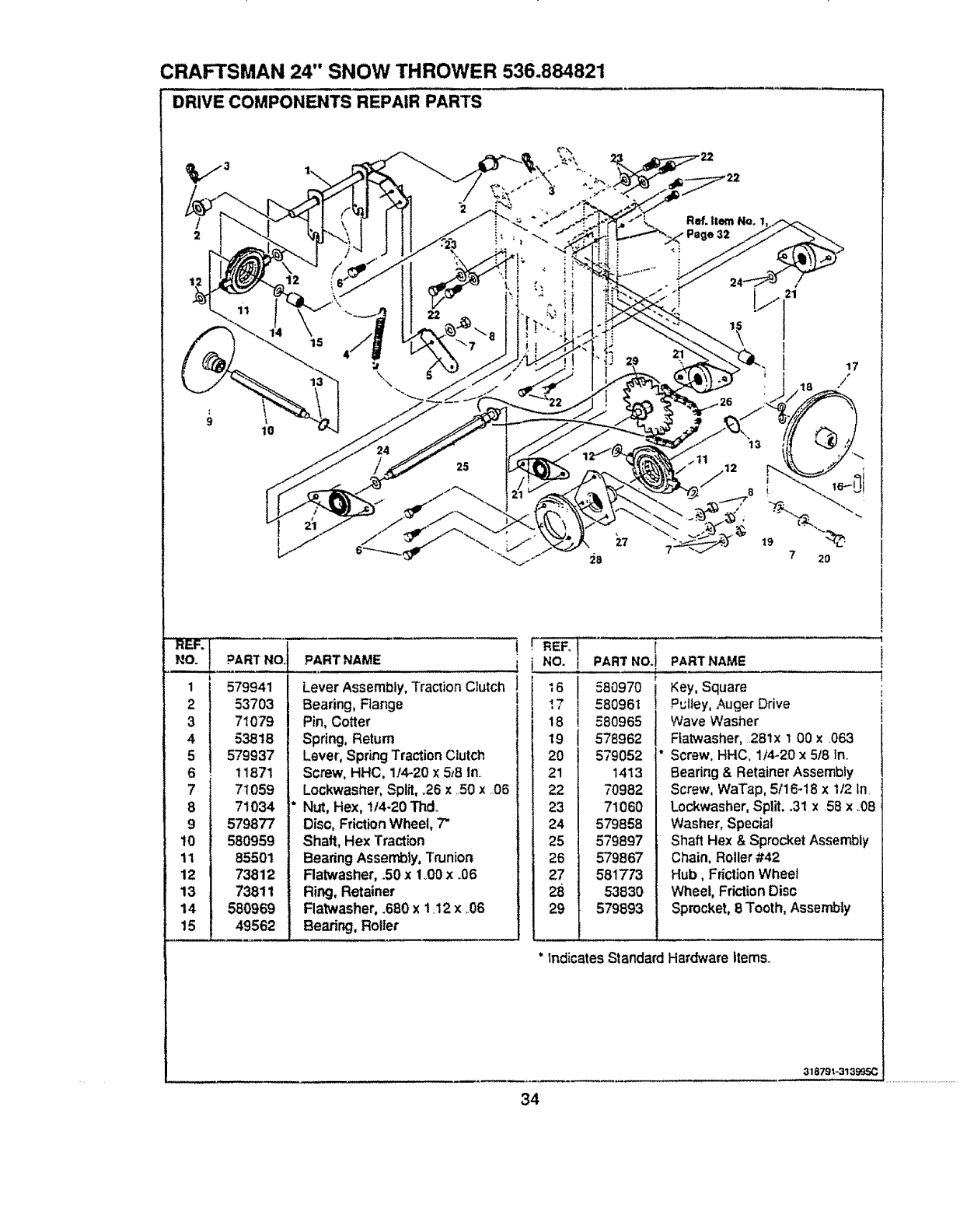
CRAFTSMAN 24" SNOW THROWER 536.884821
DRIVE COMPONENTS REPAIR PARTS
2
\
lO
12
I15
17
/
REF_¸
NO.
1
2
3
4
5
6
7
8
9
t0
11
12
13
14
t5
PART NO
579941
53703
71079
53818
579937
11871
71059
71034
579877
580959
85501
73812
73811
580969
49562
PART NAME ..!
Lever Assembly, Traction Clutch !
Bearing, Flange !
Pin, Cotter
Spring, Return
Lever, Spring Traction Clutch
Screw, HHC. 1./4-20 x 5_8 In
Lockwasher, Split, ,26 x,50 x,,06
NLrt, Hex, !/4-20 Tnd,.
Disc, Friction Wheel, "7"
Shaft, Hex Traction
Bearing Assembly, Trunion
Ratwasher, .50 xI _00x.06
Ring, Retainer
Flatwasher, .680 x 1.12 x ,.06
Bearing, Rolter
r i,1
16
_7
;8
19
20
21
22
23
24
25
28
27
28
29
{
PART NO.J
580970 j
580961
580965
578962
579052 *
1413
70982
71060
579858
579897
579867
581773
53830
579B93
PARTNAME
Key, Square
Pulley, Auger Drive
Wave Washer
Ftatwasher, ,281x 1 00 x ,063
Screw. HHC, 1)4-20 × 5/8 In.
Bearing & Retainer Assembty
Screw, WaTap, 5/16-18 x i/2 In
Lockwasher, Split..31 x 58 x ,,08
Washer, Special
Shaft Hex & Sprocket AssembJ),,
Chain, Roller #42
Hub, Friction Wheel
Wheel, Friction Disc
Sprocket, 8 Tooth, Assembly
IndicatesStandard Hardware Items.
!
......1
34
318791-313995C
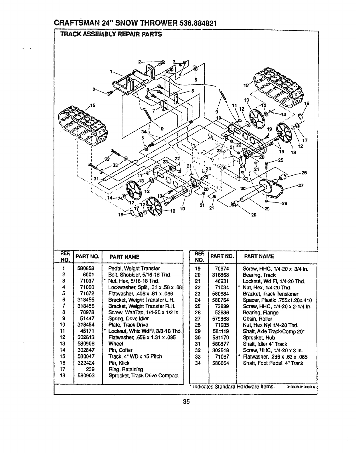
CRAFTSMAN 24" SNOW THROWER 536.884821
TRACK ASSEMBLY REPAIR PARTS
/
lO
19 18
REF. PART NO. PART NAME
NO.
1 58O658
2 6o0!
3 71037
4 71060
571072
6 318455
7 318456
870978
9 51447
10 318454
11 45171
12 302613
13 580906
14 302847
15 580047
16 322424
i7 239
18 580903
Pedal,WeightTransfer
Bolt,Shoulder,5116-18Thdo
Nut, Hex, 5/16_18Thd.
Lockwasher,Split,.31 x .58x ..08
Flatwasher, .406xo81x.066
Bracket, WeightTransfer LoHo
Bracket, WeightTransfer RoH_
Screw, WahTap,1/4-20 x 1/2 In,
Spring, DriveIdler
Plate, Track Drive
Lockrut,WhizWdFI, 3/8-16 Thd_
Ratwasher,.656 x 1,,31x °095
V,[neel
Pin,Cotter
Track,4" WDx 15 Pitch
Pin,Ktick
Ring,Retaining
Sprocket,Track Drive Compact
35
NO.
19
20
21
22
23
24
25
26
27
28
29
30
31
32
33
34
PART NO.
70974
316863
46931
7t 034
580634
580764
73839
53836
579868
71035
581119
581170
580877
302618
71067
580654
PART NAME
Screw, HHC, 1/4-20x 3f4 In.
Bearing,Track
Lockn_Jt,Wd Fi, 1/4-20Thd.
Nut,Hex, 1/4-20 Thd_
Bracket,TrackTensioner
Spacer,Plastic.755xl.20xA10
Screw,HHC, 1/4-20 x 2-1/4 In..
Bearing,Flange
Chain, Roller
Nut, Hex Nyl t/4-20 Thd.
Shaft,Axle TracldComp20"
Sprocket,Hub
Shaft, Idler4" Track
Screw, HHC, 1/4-20x 3 In,
Flalwasher, ,286 x .63 x ..065
Shaft, Foot Pedal, 4" Track
indicates Standard Hardware Items. 31_3o-313_9A,
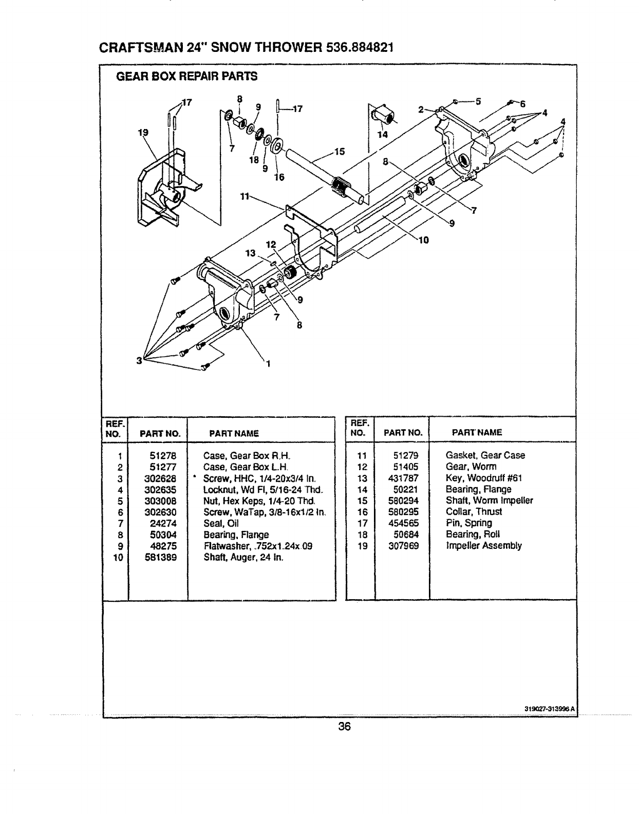
CRAFTSMAN 24" SNOW THROWER 536.884821
GEAR BOX REPAIR PARTS
16 916
12
RERI
NO.
II
21
31
41
51
61
71
81
91
101
PARTNOr
_J
51278
51277
302628
302635
303008
302630
24274
5O304
48275
581389
PART NAME
Case,Gear Box RHo
Case,Gear BoxL.H.
Screw,HHC, 1t4-20x3/4 in.
Locknut,Wd Fi, 5/16-24 Thd.
Nut,Hex Keps, 1/4-20 Thd_
Screw,WaTap, 3/8-16x112In.
Seal, Oil
Bearing,Range
Ratwasher,.752x1,24x 09
Shaft,Auger,24 In.
REF.
NO.
11
12
13
14
15
16
17
18
19
PART NO. PART NAME
51279
51405
431787
50221
580294
580295
454565
50684
307969
Gasket, Gear Case
Gear, Worm
Key, Woodruff #61
Bearing, Range
Shaft, Worm Impeller
Collar, Thrust
Pin, Spring
Bearing, Roll
Impeller Assembly
319027-313996 A
36
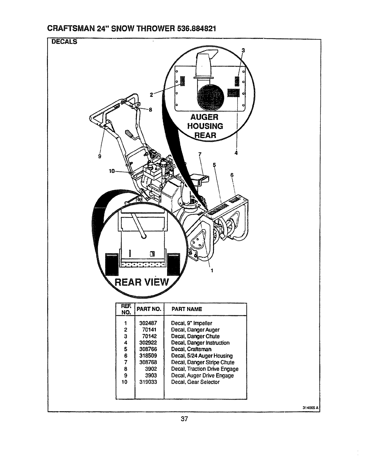
CRAFTSMAN 24" SNOW THROWER 536.884821
DECALS
AUGER 1
HOUSING
97
6
\\
REAR viEw
_ ipA-'_T.o.
NO.
1
2
3
4
5
6
7
8
9
10
302487
70141
70142
302922
3O8766
318509
308768
3902
3903
319033
PART' NAME
Decal.9"impefler
Decal,DangerAuger
Decal,DangerChute
Decal,Dangertr_'lnJctJon
Decal,Craftsman
Decal,5124AugerHousing
Decal,DangerStripe Chute
Decal,TractionDrive Engage
Decal,Auger DriveEngage
Decal, Gear Selector
314005 A
37
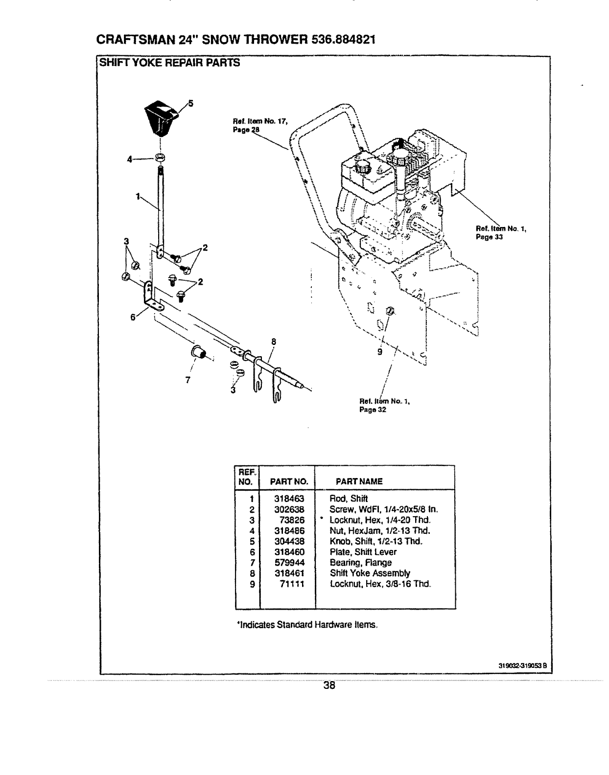
CRAFTSMAN 24" SNOW THROWER 536.884821
SHIFT YOKE REPAIR PARTS
7
/
REF_
NO, PART NO.
1 318463
2 302638
3 73826 "
4 318486
5 304438
6 318460
7579944
8 318461
9 71111
PARTNAME
Rod,Shift
Screw,WdFI, 1/4-20x5/8 In_
Locknut,Hex, 1/4-20 Thd.
Nut, HexJam,112_13Thd.
Knob,Shift,112-13Thd.
Plate, ShiftLever
Bearing,Range
ShiftYoke Assembly
Locknut,Hex,3/8-16 Thd.
"IndicatesStandardHardwareitems.,
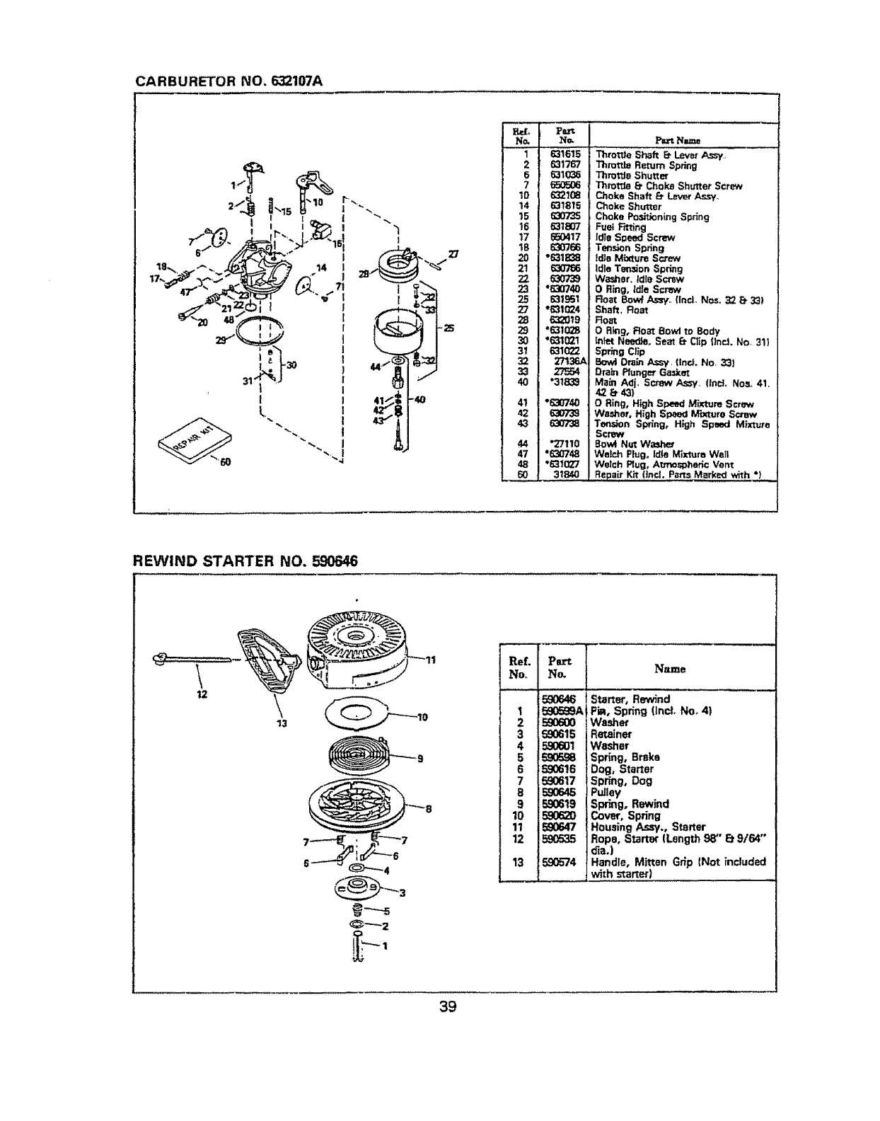
CARBURETOR NO, 632107A
N_
1
2
6
?
10
14
15
16
17
lB
29
31
4O
41
42
43
47
48
_60
P_
No. Pa_ Name
631615 Throt'Je Shaft E_Lever As:sy,:...........
631767 Throttle Return Spring
631036 Throttle Shutter
650506 Throt_ _Choke Shutter Screw
632108 Choke Shaft _ Lever As_,_i,.
631815 Choke Shutter
630735 Choke Portioning Spring
631807 Fuel F'_-ting
650417 Idle Speed Screw
630766 Tension Spring
*631838 idle Mbrtum Screw
630756 Idle Tendon St_ri_g
630739 Washer. Idle Screw
*630740 ORing, idle Screw
6319=31 Roar Bowl Assy,, find. Nos. 32 B 33)
*6316124 Shaft, Roar
6320_9 : Roar
'63102B O Ring, Roar Bowl to Body
"631021 infer NeedJe. Seat B. Clp {Ind. NOr 311
631O22 Spr_ng Clp
27t36A Bowl Drain Assy. (Incl. No, 33)
2"F354 Drain Plunger Gasket
"31839 Ma_n Ad]. Scow Assy #ind, Nos. 41.
42 _43)
°630740 O Ring, H_gh Speed Mixture Screw
6307"39 Washer, High Speed Mixture Screw
630"T_ Tension Spring, High Speed Mixture
Screw
*27110 Bow4 Nut Wa_rter
"630748 Welch Plug, Idle Mixture Well
"631027 Welch Rug, Atrnosoheric Vent
31840 Repair Kit (incl. Parts Marked with "1
REWIND STARTER NO. 590646
\
12
13
Ref.
Noo
1
2
3
4
5
6
7
8
9
10
11
12
13
P_ I
No Name
590646 fStarter, Rewind
5905_A| PiA, Spring (Ind. No_ 4)
E90600 !Wa_er
590615 i Retainer
590601 I Washer
590598 I Spring, Brake
590616 t Dog, Starter
590617 ]Spdng, Dog
590645 JPulley
590619 I Spring, Rewind
JCover, Spring
590647 (Housing Assy., Starter
] Rope, Starter (Length 98" Et 9/64"
o'ia.)
5.90574 JHandle, Mitten Grip (Not included
with starter)
39
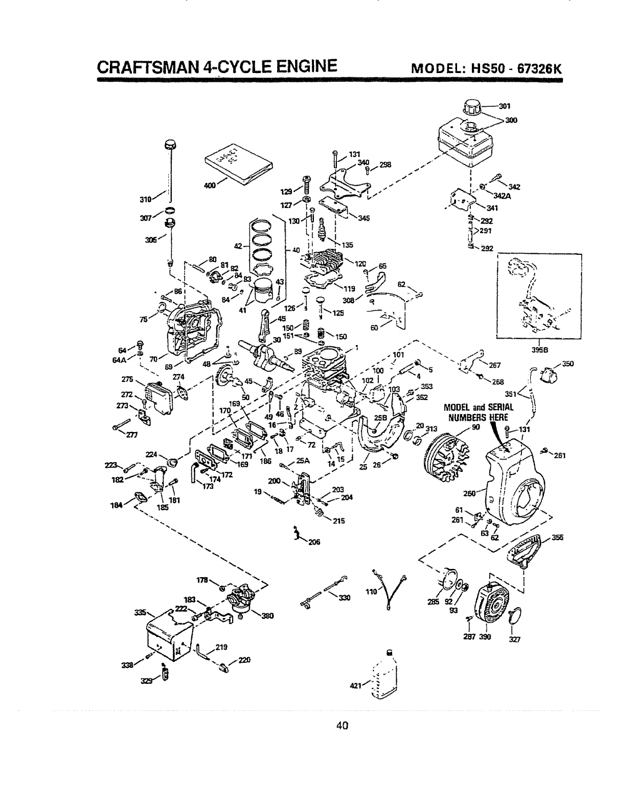
CRAFTSMAN 4-CYCLE ENGINE
=IIqII1' Ilql J
MODEL: HSS0- 67326K
IIIIII II III1'111111
!
!
t
i
131
173
4O
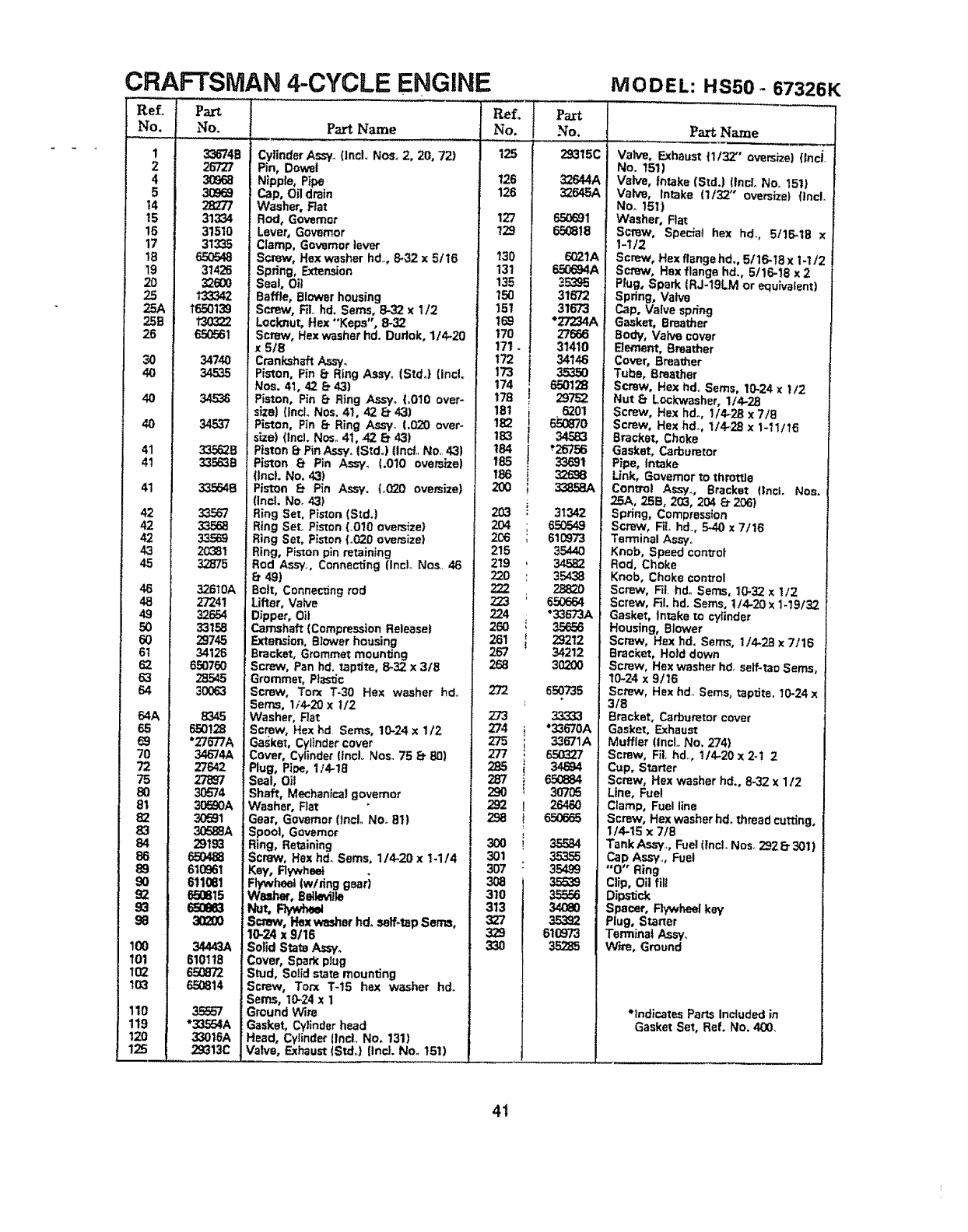
CRAFTSMAN 4-CYCLE ENGINE
ReL ................ "......
No.
I
2
4
5
14
t5
16
17
18
t9
20
25
25A
258
26
3O
40
4O
40
41
4t
41
42
42
42
43
45
46
48
49
50
60
61
62
63
64
64A
65
69
70
72
75
80
81
82
83
84
86
89
9O
92
93
98
100
101
102
103
110
119
t2o
125
No.
33674B
26727
30968
30369
28277
31334
31510
31335
650548
31426
326OO
133342
1650139
13O322
650561
34740
34535
345_
34537
33562B
335636
335646
33.%'7
33568
33589
20381
32875
32610A
27241
32854
33158
29745
34126
650760
28545
3OO63
8345
650128
"276"]7A
34674A
27642
27897
3O574
30590A
30591
30588A
29193
650488
610961
611081
65O815
65O883
3O2O0
34443A
610118
650872
650814
35557
"33554A
33016A
29313C
Part Name
Cylinder Assy. (IncL Nee. 2, 20, 72)
Pin, Dowel
Nipple, Pipe
Cap, Off drain
Washer, Flat
Rod, Governor
Lever, Governor
Clamp, Governor lever
Screw, Hex washer hd.,, 8,32 x 5!16
Spring, Extension
Seat, Oil
Raffle, Blower housing
Screw, RI,. hd. Seres, 8-32 x1/2
Locknut, Hex "'Keps', 8-32
Screw, Hex washer hd. Dudok, 114.20
x 5/8
Crankshaft As_,_
Piston, Pin 8. Ring Assy_ (Std°) (incL
Nee. 41, 42 8. 43)
Piston, Pin 8. Ring Assyo (.010 over-
size) (lncL Nos, 41, 42 _43)
Piston, Pin 8. Ring Assy_ (.020 over-
size) (lncl. Nose41, 42. _ 43)
Piston 8. PinAssy. (Std.) (IncL No,, 43)
Piston _ Pin A._f, (.010 oversize)
(IncL No, 43)
Piston 8. Pin Assy. (_020 oversize)
(incl. No. 43)
Ring Set, Piston (StdJ
Ring Set. Piston (.O10 oversize)
Ring Set, Piston (_020 oversize)
Ring, Piston pin retaining
Rod Ass'y. Connecting (IncL Nos., 46
8.49)
Bolt, Connec_ng rod
Lifter, Valve
Dipper, Oi!
Camshaft (Compression Release!
Extension, Biower housing
Bracket, Grommet mounting
Screw, Pan hd. taptite, 8-32 x 3/8
Grommet, Ptasdc
Screw, Tort %30 Hex washer hdo
Sems, 1/4-20 x 1/2
Washer, Rat
Screw, Hex hd Serns, t0-24 x I/2
Gasket, Cylindercover
Cover, Cytinder (tncL Nos. 75 t_ 80)
Plug, Pine. 1/4.18
Seat, Oil
Shaft, Mechanical governor
Washer, Flat
Gear, Governor 0ncL No_ 81)
Spool, Governor
Ring, Retaining
Screw, Hex hd_Seres, 1/4.20 x t-1/4
Key, Rywheet
Rywheet (w/_ing gsari
W_her, Relleville
Nut,P_/w_
Screw, Hex wesher hd° serf-tap Seres,
10-24 x 9!16
,Solid State Assyo
Cover, Spark plug
:Stud, Sotid state mounting
Screw, Torx %15 hex washer hd_
Seres, 10=24 xi
Ground Wire
Gasket, Cylinder head
Head, Cytinder {tncL No. 131)
Valve, Exhaust {StdJ (incl. No. 151)
ReL Part
No. No.
125
126
126
127
129
29315C
32644A
32645A
65O691
650818
130 6021A
131 650694A
135 353_S
i50 31672
151 31673
169 "27234A
170 27666
171 .! 31410
172 34146
173 35350
174 65O128
178 297=32
18t i6201
lS2 r_o
183 34583
184 *26756
185 33691
186 i
20O i33868A
203 i3_342
204 ; 650549
206 ; 610973
215 35440
219 34582
220 : 35438
288_o
223 ;656664
224 "33673A
260 _35656
251 i 29212
267 34212
268 30200
272 650735
273 33333
274 i"33670A
275 ; 33671A
277 : 650327
287 " _
290 _30705
292 I26460
i
307 : 35499
310 35556
313 34O80
327 35392
329 610973
330 35285
MODEL: HS50- 673261_
Part Name
tValve, Exhaust 11132" oversize} (Inci,,
Io. 1511
Valve, Intake (Std.) !!ncL No,. 151)
| Valve, intake (1/32 oversizet (lncL
] No, 161)
|Washer, Fiat
| Screw, Special hex hd., 5t1_18 x
| 1-1/2
|Screw, Hex fiangehd., 5/16.18x 1-1/2
|Screw, Hex flange hd., 5/16-18 x 2
| Prug. Spark {RJ-t9LM or equivalent)
|Spring, Valve
| Cap, Valve spring
Gasket, Breather
|Body, Valve cover
Bement, Breather
/Cover, Breather
Tube, Breather
Screw, Hex hdo Seres, 10-24 x 112
Nut _Lockwasher, 1/4-23
Screw, Hex hd. 1/4,28 x 7/8
Screw, Hex hd. 1/4.28 x %11/16
Bracket, Choke
Gasket, Carburetor
Pipe, Intake
Unk, Governor to throttle
Cent]tel As_., Bracket (Incl. Nos.
25A, 258, 203, 204 6"206)
Spring, Compression
Screw, FiL hd., 540 x 7/16
Terminal Assyo
Knob, Speed control
Rod, Choke
Knob, Choke control
Screw, Fil, hd_ Seres, 10-32 x I12
Screw, FiL hd. Seres, 1/4.20x 1-19/'32
Gasket, Intake to cylinder
Housing, Blower
Screw, Hex hd. Seres, 1/4.28 x 7/16
Bracket, Hoid down
Screw, Hex washer hd, self-too Seres,
t0-24 x 9/16
Screw, Hex hd_ Seres, top,ire, 10.24 x
3/8
Bracket. Carburetor cover
Gasket. Exhaust
Muffler (Incl. No, 274)
Screw, FiL hd,,, t/4.20x 2-t 2
Cup, Starter
Screw, Hex washer hd. 8-32 x 1/2
Line, Fuel
Cramp, Fuel line
Screw, Hex washer hd. thread cutting,
1/4-15 x 7/8
Tank Assy. Fuel (tncL Nose 2928- 301)
CaP As.w,,, Fuel
"0" Ring
Clip, Oil flit
Oipe_c_
Spacer, RywPmel key
Plug. Start{'
Terminat A_ ,_,
Wire, Grout d
*Indical _ Parts Included in
Gaske! Set, Ref. No. 400,
41
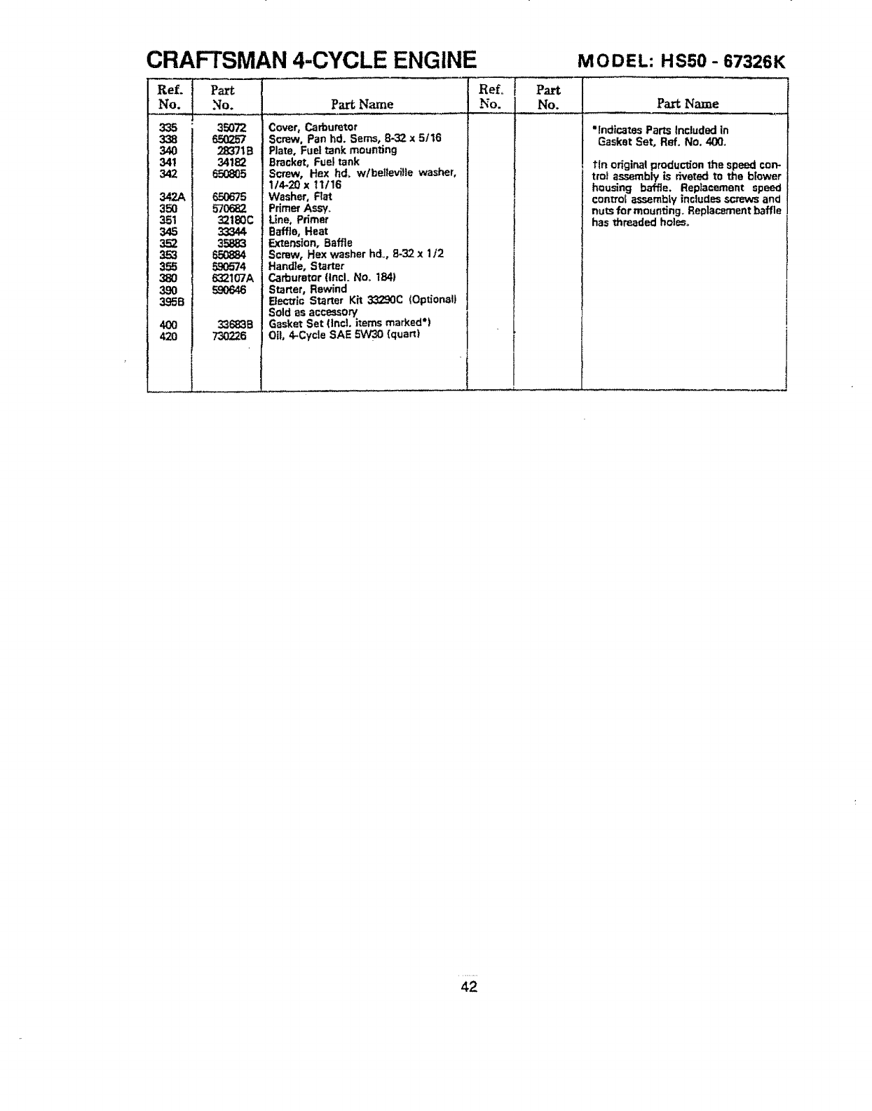
CRAFTSMAN 4-CYCLE ENGINE
335
338
340
341
342
342A
350
35t
345
352
353
355
380
3,9O
395B
4OO
420
Part
No. Part Name
35O72
28371B
34182
65_05
65O675
57O682
321_0C
33344
35883
650884
590574
632107A
59O646
33683B
73O226
Cover, Carburetor
Screw, Pan hd. Seres, 8-32 x 5116
Plate, Fuel tank mounting
Bracket, Fuel tank
Screw, Hex hd, w/bellevilie washer,
1/4_20 x tl/16
Washer, Rat
Primer Assy_
Line, Primer
B_ffia, Heat
Extension, Baffle
Screw, Hex washer hd_, 8.32 x1/2
Hand]e, Starter
Carburetor (Incl, No. 1841
Starter, Rewind
Electric Starter Kh 33290C (Optional)
Sold as accessory
GBsket Set ()ncL i_ems marked')
Oil, 4*Cyc|e SAE 5W30 {quart)
MODEL: HSS0 - 67326K
PartName
•indicatesPartsIncludedin
GasketSet, Ref. No. 400,
tin original production the speed con-
tro) assembly is dveted to the blower
housing baffle. Replacement speed
control assembly includes screws and
nuts for mounting, Replacement baffle
has threaded holes_
42

.....ii ,,,
i,, "OTES.........................._]
+ .... +L:++L _L+: :,_ LH'I"""I'+III"'1' ' '1 I" I" I
43
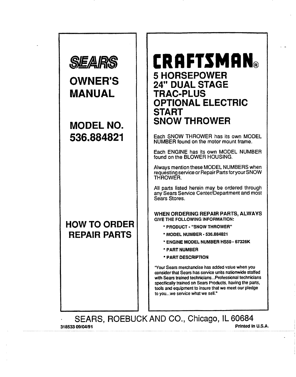
OWNER'S
MANUAL
MODEL NO.
536.884821
HOW TO ORDER
REPAIR PARTS
CRAFTSMAN,+
5 HORSEPOWER
24" DUAL STAGE
TRAC-PLUS
OPTIONAL ELECTRIC
START
SNOW THROWER
Each SNOW THROWER has its own MODEL
NUMBER found on the motor mount frame.
Each ENGINE has its own MODEL NUMBER
found on the BLOWER HOUSING++
Always mention these MODEL NUMBERS when
requesting service or Repair Parts for your SNOW
THROWER+
All parts listed herein may be ordered through
any Sears Service Center/Department and most
Sears Stores.
WHEN ORDERING REPAIR PARTS, ALWAYS
GIVE THE FOLLOWING INFORMATION:
* PRODUCT= =SNOWTHROWER"
* MODEL NUMBER - 536.884821
* ENGINE MODEL NUMBER HSS0- 67326K
"PART NUMBER
"PART DESCRIPTION
"YourSears merchandise hasadded valuewhen you
considerthat Sears has serviceunitsnationwidestaffed
withSears trainedtechnicians++,Prolessionaltechnicians
specificallytrainedonSears Products,havingthe parts,
toolsandequipmentto insurethat we meetour pledge
to you+++weservicewhatwe sell,"
SEARS, ROEBUCK AND CO., Chicago, IL 60684
318533 09104/91 Printed in U.S.A.
