Sears Kenmore 625 348234 Users Manual
625348234 625348234 KENMORE WATER FILTERS - Manuals and Guides L0803149 View the owners manual for your KENMORE WATER FILTERS #625348234. Home:Plumbing Parts:Kenmore Parts:Kenmore WATER FILTERS Manual
KENMORE Water filter Manual L0803149 KENMORE Water filter Owner's Manual, KENMORE Water filter installation guides
Kenmore 625.348234 L0803149
625.348241 to the manual 8b5dee9d-23cf-4c45-a552-554da6d29d60
2015-02-05
: Sears Sears-Kenmore-625-348234-Users-Manual-399751 sears-kenmore-625-348234-users-manual-399751 sears pdf
Open the PDF directly: View PDF ![]() .
.
Page Count: 28
_ARS
OWNER'S
MANUAL
MODEL NOS.
625.348234
Clarifier
625.348241
Neutralizer
625.348251
Taste & Odor
Caution:
Read and Follow
All Safety Rules and
Operating Instructions
Before First Use of
This Product.
If you have questions when
installing, operating or main-
taining your filter, and when
setting the timer, call this
toll-free number...
1-800-426-9345
SAVE THIS MANUAL
Kenmore
Water Filters
• Warranty
• Start Up /Setting Timer
• How It Works
• Care Of
• Specifications
• Repair Parts
Sears, Roebuck and Co., Hoffman Estates, IL 60179 USA
PRINTED IN U.S.A.

WARRANTY
I I
SEARS RESIDENTIAL WATER FILTER
FULL ONE YEAR WARRANTY ON FILTER
For one year from the date of purchase, when this water filter is installed and maintained in
accordance with our instructions, Sears will repair, free of charge, defects in materials or
workmanship in this water filter.
FULL FIVE YEAR WARRANTY AGAINST LEAKS
For five years from the date of purchase, Sears will furnish and install a new current model water
filter tank, free of charge, if the tank develops a leak.
TO OBTAIN WARRANTY SERVICE, SIMPLY CONTACT THE NEAREST SEARS SERVICE
CENTER THROUGHOUT THE UNITED STATES. "This warranty applies only while this product
is in use in the United States."
This warranty gives you specific legal rights, and you may have other rights which vary from state
to state.
Sears, Roebuck and Co., D/817 WA, Hoffman Estates, IL 60179
If you want your water filter professionally installed, talk to your Sears Salesman. He will arrange for a prompt,
quality installation by Sears Authorized installers.
SEARS INSTALLATION POLICY
All installation labor arranged by Sears shall be per-
formed in a neat, workmanlike manner in accordance
with generally accepted trade practices. Further, all
installations shall comply with all local laws, codes,
regulations and ordinances. Customer shall also be
protected, during installation, by insurance relating to
Property Damage, Workman's Compensation and
Public Liabilility.
SEARS INSTALLATION WARRANTY
In addition to any warranty extended to you on
the Sears merchandise involved, which warranty
becomes effective the date the merchandise is
installed, should the workmanship of any Sears
arranged installation prove faulty within one year,
Sears will, upon notice from you, cause such faults to
be corrected at no additional cost to you.
FACTS AND FIGURES TO KEEP
Fill in the blanks below and keep this book in
a safe place so you always have these facts.
Water Filter Model No. 1"
Serial Number
Date Installed
Iron Content Parts Per Million
*pH Taste And/Or Odor
Water Pressure Pounds/Square Inch
Water Flow Rate Gallons Per Minute
tThe model number is on the rating decal,
located on the back of the filter top cover.
2
TABLE OF CONTENTS
[ I
SECTION 1 FILTER START UP
A. SAFETY GUIDES
B. CHECK LIST OF STEP-BY-STEP GUIDES TO INSTALL
C. SANITIZING THE WATER FILTER
D. PROGRAM THE TIMER
PAGE
NO.
4
5
6
7-8
SECTION 2 HOW YOUR WATER FILTER WORKS
A. FACE PLATE TIMER FEATURES 9-10
B. FILTER APPLICATIONS 11
C. FILTERED WATER SERVICE, AND BACKWASH 12
SECTION 3 CARE OF YOUR FILTER
A. KEEP THE FILTER FROM FREEZING
B. ADDING MINERAL... NEUTRALIZER FILTER
C. REPLACING MINERAL... TASTE & ODOR FILTER
D. HELPFUL HINTS CHECKLIST
13
14-15
16
17
SECTION 4 OTHER THINGS TO KNOW
A. DIMENSIONS/SPECIFICATIONS 18
SECTION 5 SERVICER'S TECH INFORMATION
A. ELECTRICAL CONNECTIONS
B. BACKWASH CYCLE TIMES
C. DIAGNOSTICS
D. "QUICK-CHECK" TROUBLESHOOTING
E. ROTARY VALVE SERVICE
F. WATER FLOW THROUGH THE FILTER VALVE
19
20
21
22
23
24
SECTION 6 REPAIR PARTS 25-27
3
SECTION 1
I
1A, SAFETY GUIDES
•Read all steps, guides and rules carefully
before installing and using your new water filter.
Follow all steps exactly to correctly install. Fail-
ure to follow them could cause personal injury
or property damage. Reading this book will also
help you to get all of the benefits from your water
filter.
•Your water filter will improve your water as
described on page 11. It will not soften water or
remove iron. It will not purify polluted water or
make it safe to drink. Also see the specifications
on page 18.
•Protect the filter and piping from freezing.
Damage from freezing voids the filter warranty.
See page 13.
PLEASE READ AND COMPLY WITH THE
FOLLOWING GUIDES TO PREVENT
DAMAGE TO THE FILTER OR OTHER
PROPERTY, PERSONAL INJURY, OR POS-
SIBLE FATAL SHOCK.
•THIS FILTER WORKS ON 24 VOLTS ONLY.
BE SURE TO USE THE TRANSFORMER IN-
CLUDED, AND PLUG IT INTO A 120V OUTLET.
•Unplug the transformer right away if the
power cable should become damaged or frayed.
Make repairs before plugging back into the
power outlet.
•Always unplug the filter from electrical
power before removing outer valve covers.
4
SECTION 1 WATER FILTER START-UP
I I
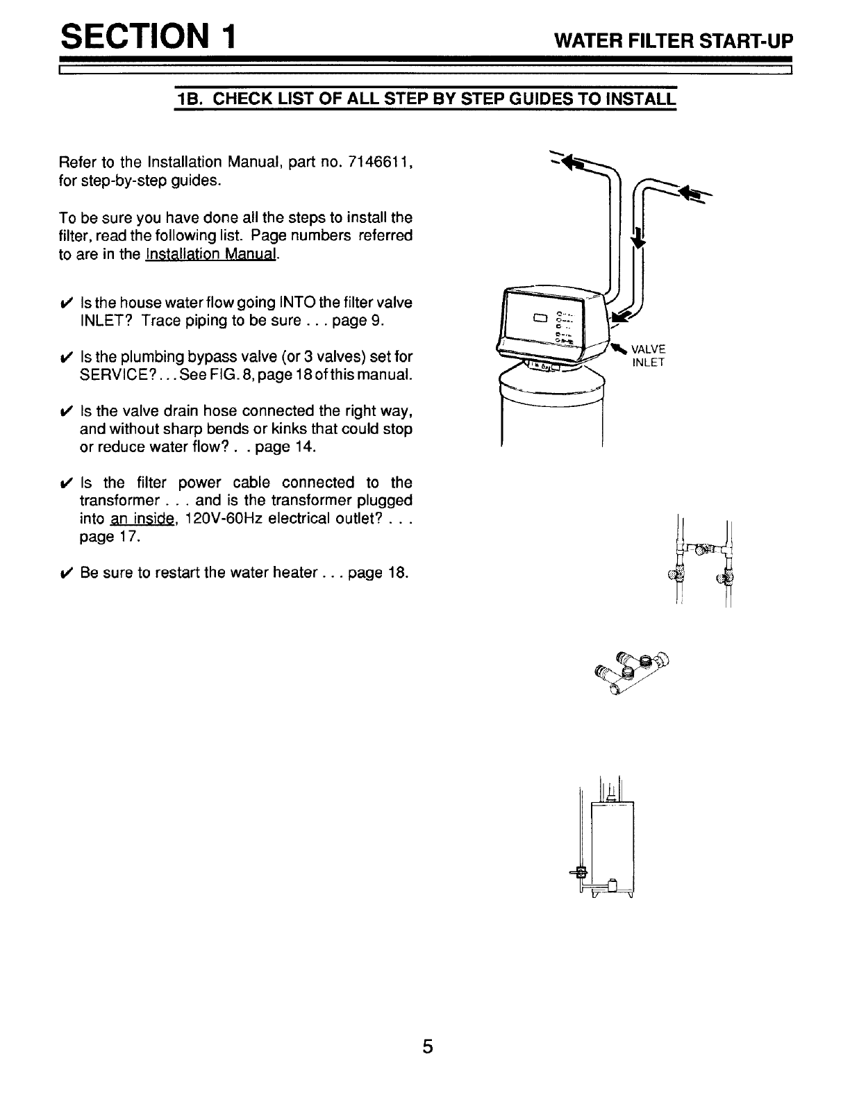
lB. CHECK LIST OF ALL STEP BY STEP GUIDES TO INSTALL
Refer to the Installation Manual, part no. 7146611,
for step-by-step guides.
To be sure you have done all the steps to install the
filter, read the following list. Page numbers referred
to are in the Installation Manual.
Is the house water flow going INTO the filter valve
INLET? Trace piping to be sure.., page 9.
Is the plumbing bypass valve (or 3 valves) set for
SERVICE?... See FIG. 8, page 18 ofthis manual.
Is the valve drain hose connected the right way,
and without sharp bends or kinks that could stop
or reduce water flow?., page 14.
v' Is the filter power cable connected to the
transformer.., and is the transformer plugged
into an inside, 120V-60Hz electrical outlet?...
page 17.
Be sure to restart the water heater.., page 18.
VALVE
INLET
SECTION 1 WATER FILTER START-UP
I
10.
1
SANITIZING THE WATER FILTER
Care is taken at the factory to keep your water filter
clean and sanitary. Materials used to make the filter
will not infect or contaminate your water supply, and
will not cause bacteria to form or grow. However,
during shipping, storage, installing and operating,
bacteria could get into the filter. For this reason,
sanitizing as follows is suggestedG when installing.
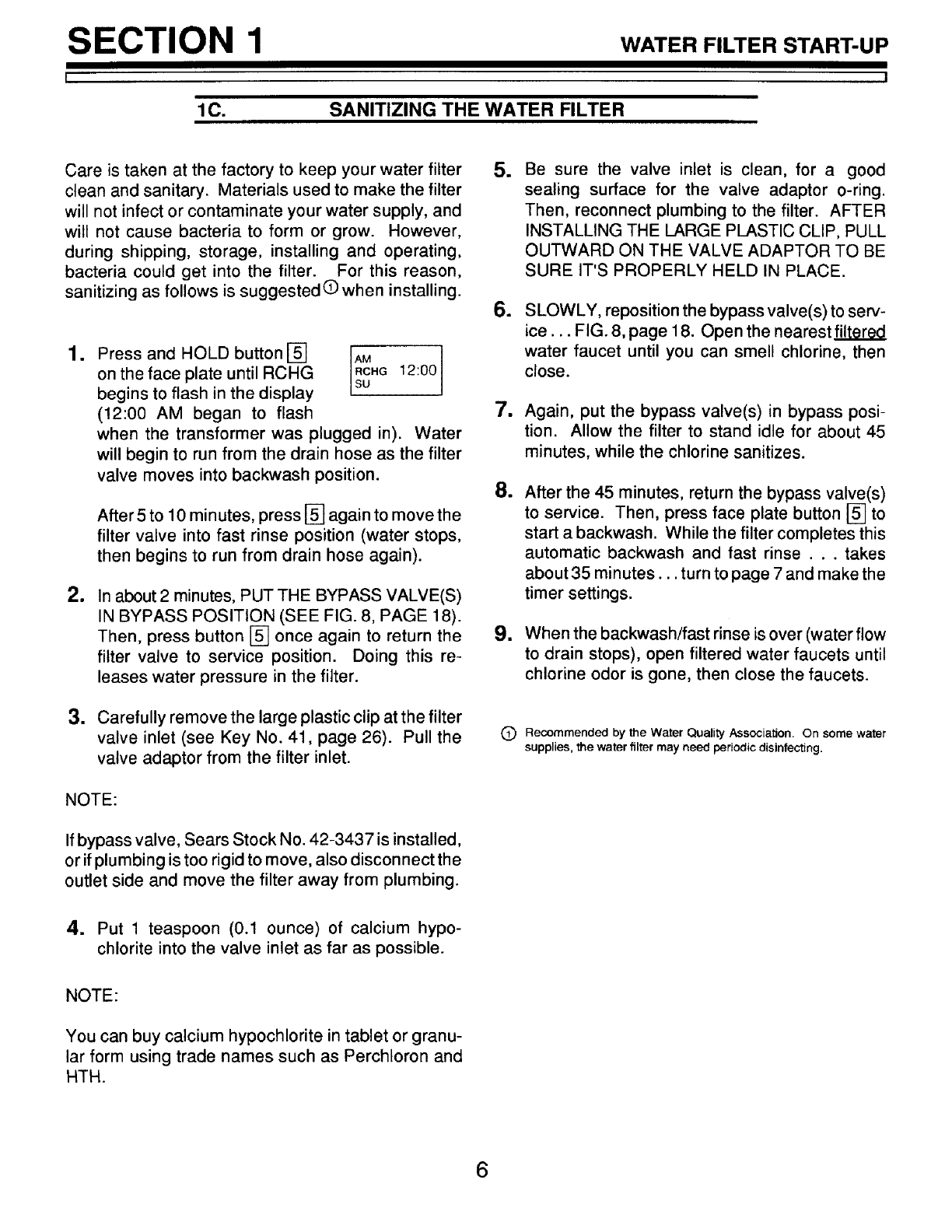
1
Press and HOLD button [] _cMHG12:00
on the face plate until RCHG
begins to flash in the display su
(12:00 AM began to flash
when the transformer was plugged in). Water
will begin to run from the drain hose as the filter
valve moves into backwash position.
After 5 to 10 minutes, press [] again to move the
filter valve into fast rinse position (water stops,
then begins to run from drain hose again).
mIn about 2 minutes, PUT THE BYPASS VALVE(S)
IN BYPASS POSITION (SEE FIG. 8, PAGE 18).
Then, press button [] once again to return the
filter valve to service position. Doing this re-
leases water pressure in the filter.
3. Carefully remove the large plastic clip at the filter
valve inlet (see Key No. 41, page 26). Pull the
valve adaptor from the filter inlet.
NOTE:
If bypass valve, Sears Stock No. 42-3437 is installed,
or if plumbing is too rigid to move, also disconnect the
outlet side and move the filter away from plumbing.
m
6.
m
1
1
Be sure the valve inlet is clean, for a good
sealing surface for the valve adaptor o-ring.
Then, reconnect plumbing to the filter. AFTER
INSTALLING THE LARGE PLASTIC CLIP, PULL
OUTWARD ON THE VALVE ADAPTOR TO BE
SURE IT'S PROPERLY HELD IN PLACE.
SLOWLY, reposition the bypass valve(s) to serv-
ice... FIG. 8, page 18. Open the nearest_
water faucet until you can smell chlorine, then
close.
Again, put the bypass valve(s) in bypass posi-
tion. Allow the filter to stand idle for about 45
minutes, while the chlorine sanitizes.
After the 45 minutes, return the bypass valve(s)
to service. Then, press face plate button [] to
start a backwash. While the filter completes this
automatic backwash and fast rinse . .. takes
about 35 minutes.., turn to page 7 and make the
timer settings.
When the backwash/fast rinse is over (water flow
to drain stops), open filtered water faucets until
chlorine odor is gone, then close the faucets.
C) Reoommended by the Water Quality Association. On some water
supplies, the water filter may need periodic disinfecting.
4. Put 1 teaspoon (0.1 ounce) of calcium hypo-
chlorite into the valve inlet as far as possible.
NOTE:
You can buy calcium hypochlorite in tablet or granu-
lar form using trade names such as Perchloron and
HTH.
6
SECTION 1 WATER FILTER START-UP
I
1D. PROGRAM THE TIMER
I
I,
display
]QPRESENT TIME AND DAY
_BACKWASH TIME
_BACKWASH DAY
_SETICLEAR
ON/OFF VACATION
V_,_.:J _ BACKWASH NOW
buttons
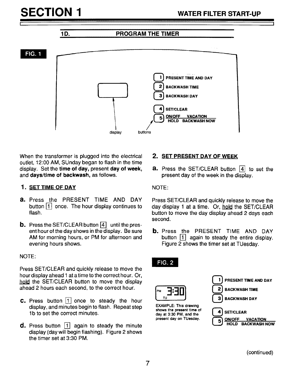
When the transformer is plugged into the electrical
outlet, 12:00 AM, SUnday began to flash in the time
display. Set the time of day, present day of week,
and days/time of backwash, as follows.
1. SET TIME OF DAY
a. Press the PRESENT TIME AND DAY
button [] once. The hour display continues to
flash.
b. Press the SET/CLEAR button [] until the pres-
ent hour of the day shows in the display. Be sure
AM for morning hours, or PM for afternoon and
evening hours shows.
NOTE:
Press SET/CLEAR and quickly release to move the
hour display ahead 1 at a time to the correct hour. Or,
hold the SET/CLEAR button to move the display
ahead 2 hours each second, to the correct hour.
C. Press button [] once to steady the hour
display, and minutes begin to flash. Repeat step
lb to set the correct minutes.
d. Press button [] again to steady the minute
display (day will begin flashing). Figure 2 shows
the timer set at 3:30 PM.
2. SET PRESENT DAY OF WEEK
a. Press the SET/CLEAR button [] to set the
present day of the week in the display.
NOTE:
Press SET/CLEAR and quickly release to move the
day display 1 at a time. Or, _ the SET/CLEAR
button to move the day display ahead 2 days each
second.
b. Press the PRESENT TIME AND DAY
button [] again to steady the entire display.
Figure 2 shows the timer set at TUesday.
I o3:30]
EXAMPLE: This drawing
shows the present time of
day at 3:30 PM, and the
present day on TUesday.
QPRESENT TIME AND DAY
{_ BACKWASH TIME
(_ BACKWASH DAY
_SETICLEAR
_ON/OFF VACATION
HOLD BACKWASH NOW
7
(continued)
SECTION 1
1D. PROGRAM THE TIMER
WATER FILTER START-UP
I
3. SET DAYS OF BACKWASH
IF YOU HAVE A WATER SOFTENER OR
OTHER AUTOMATIC FILTER, .. A good
water flow rate is needed for proper recharging
and/or backwashing of all water conditioners.
To help assure good water flow, you should
offset the timers on each conditioner so
recharges do not occur on the same days, or at
the same time.
•.. Most Sears water softeners are factory set (many
are adjustable ) to recharge from 2:00 to
4:00 am.
••• Set the filter to backwash on different days, or...
•••Set the filter to backwash either before or after
other equipment, or...
... Offset the timers on all equipment to J29.g_
recharges on backwashes at 12:00, 2:00 and
4:00 AM, or 1:00, 3:00 and 5:00 AM, etc.
a. Read the BACKWASHING GUIDE for your type
of filter.
b. Press the BACKWASH DAY BUTTON [] AND
SUnday begins to flash.
Ifyou want backwashes on Sunday (from guide),
press the SET/CLEAR button [] to display ON.
If you do not want Sunday backwashes, press
button [] to display OFF.
NOTE:
The timer is factory programmed to backwash on
Monday, Wednesday and Saturday•
C. Press button [] again to display a flashing
MOnday__ As you did in step b above, press
button 141to display ON for backwash on Mon-
day, or OFF for no backwash on Monday.
d. Press button [] for every day of the week, each
time using button [] to display ON (for back-
wash) or OFF (no backwash) as needed.
e. After setting ON or OFF for Saturday, press
button [] to return the present time in the
display.
=SET TIME OF BACKWASH
The filter is factory set to begin backwashes at
12:00 AM, ending at about 12:40 AM. If a
different backwash time is desired, or needed
(see note under step 3), do the following•
a. Press the BACKWASH TIME button [] once, to
display a flashing 12:00 AM, the factory setting•
b. Press the SET/CLEAR buttonl_]untilthe desired
backwash starting time shows in the display.
NOTE: Press button [] and quickly release to move
the display ahead 1 hour at a time. Or, hold button []
to move the display ahead 2 hours each second.
C. Press button [] to return the present time.
8
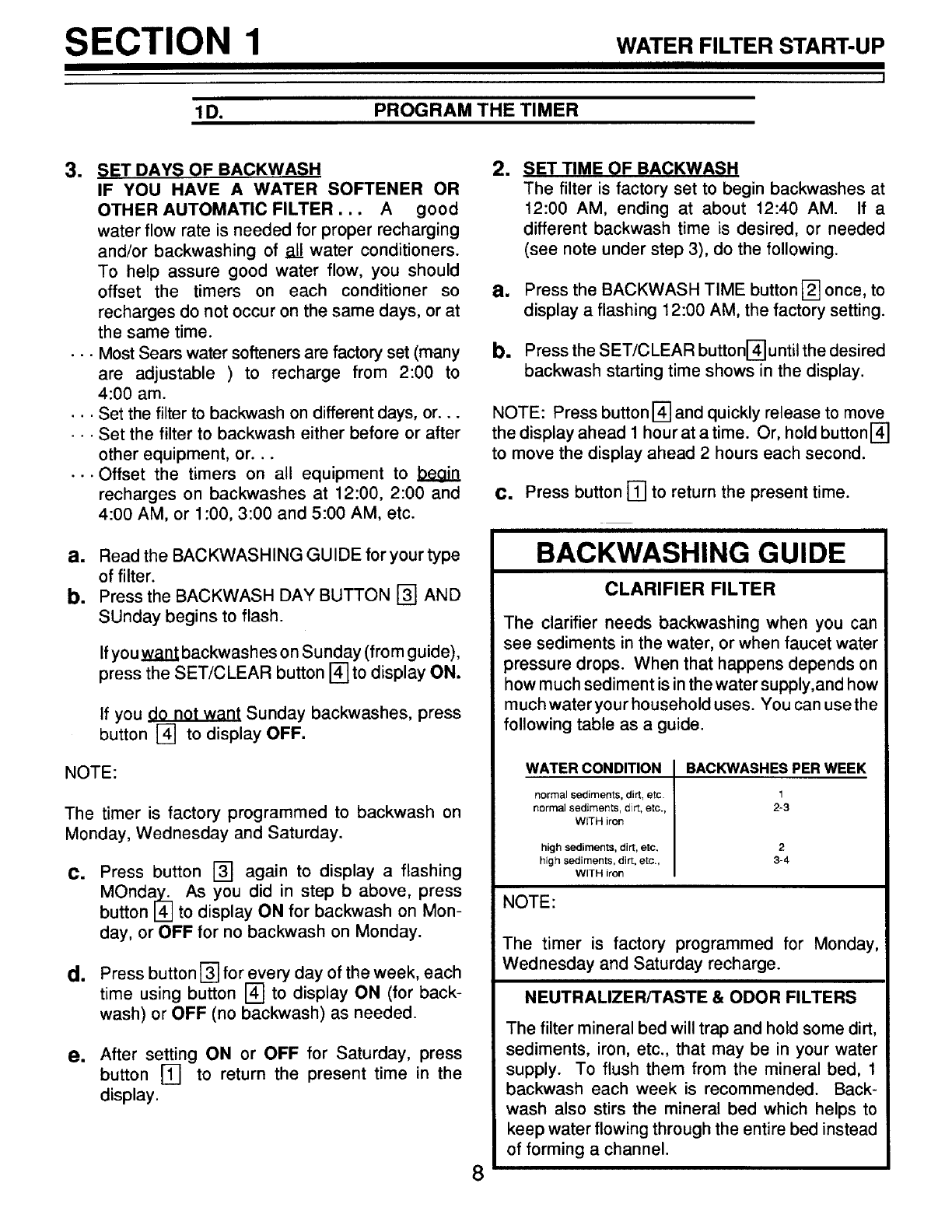
BACKWASHING GUIDE
CLARIFIER FILTER
The clarifier needs backwashing when you can
see sediments in the water, or when faucet water
pressure drops. When that happens depends on
how much sediment is in the water supply,and how
much water your household uses. You can use the
following table as a guide.
WATER CONDITION
normal sediments, dirt, etc.
normal sediments, _i_, etc.,
WITH iron
high sediments, dirt, etc.
high sediments, dirt, etc.,
WITH iron
BACKWASHES PER WEEK
1
2-3
2
3-4
NOTE:
The timer is factory programmed for Monday,
Wednesday and Saturday recharge.
NEUTRALIZER/TASTE & ODOR FILTERS
The filter mineral bed will trap and hold some dirt,
sediments, iron, etc., that may be in your water
supply. To flush them from the mineral bed, 1
backwash each week is recommended. Back-
wash also stirs the mineral bed which helps to
keep water flowing through the entire bed instead
of forming a channel.
SECTION 2 HOW YOUR WATER FILTER WORKS
I
2A.
I
FACE PLATE TIMER FEATURES
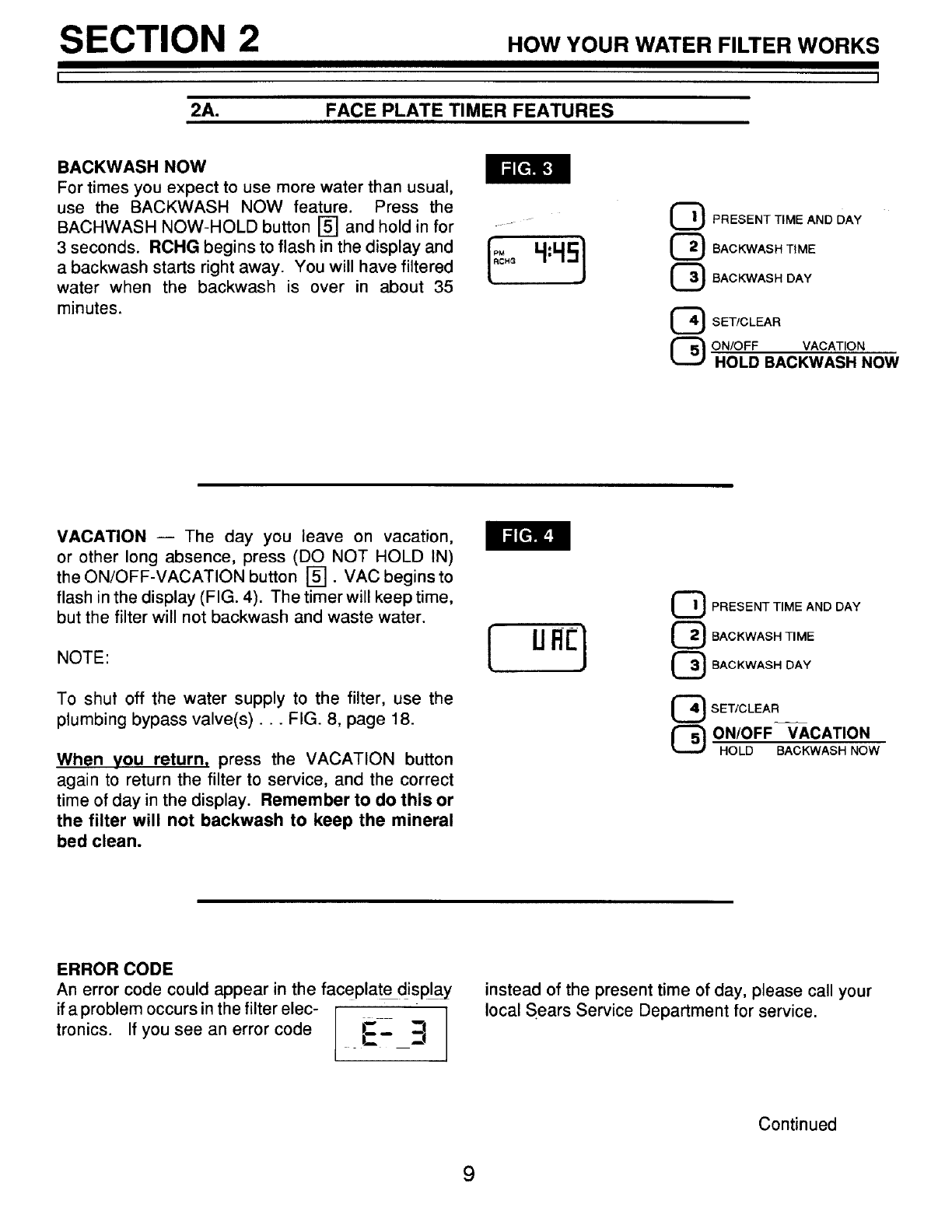
BACKWASH NOW
For times you expect to use more water than usual,
use the BACKWASH NOW feature. Press the
BACHWASH NOW-HOLD button [] and hold in for
3 seconds. RCHG begins to flash in the display and
a backwash starts right away. You will have filtered
water when the backwash is over in about 35
minutes.
_) PRESENT TIME AND DAY
_ BACKWASH DAY
SET!CLEAR
ONIOFF VACATION
HOLD BACKWASH NOW
VACATION -- The day you leave on vacation,
or other long absence, press (DO NOT HOLD IN)
the ON/OFF-VACATION button []. VAC begins to
flash in the display (FIG. 4). The timer will keep time,
but the filter will not backwash and waste water.
NOTE:
To shut off the water supply to the filter, use the
plumbing bypass valve(s)... FIG. 8, page 18.
When you return, press the VACATION button
again to return the filter to service, and the correct
time of day in the display. Remember to do this or
the filter will not backwash to keep the mineral
bed clean.
_ PRESENT TIME AND DAY
_ BACKWASH DAY
_ SET/CLEAR
_ ON/OFF VACATION
HOLD BACKWASH NOW
ERROR CODE
An error code could appear in the faceplate display
if a problem occurs in the filter elec- I
tronics. If you see an error code I!_-- _
instead of the present time of day, please call your
local Sears Service Department for service.
Continued
9
SECTION 2
2A.
HOW YOUR WATER FILTER WORKS
I
FACE PLATE TIMER FEATURES
TIMER "POWER-OUTAGE MEMORY" -- If electri-
cal power to the timer goes off, the "memory" built into
timer circuitry keeps all settings for 5 hours (mini-
mum) or more. The display is blank and the filter will
not backwash. When electrical power comes on, 1 of
2 things will happen.
1. The present time of day will show, meaning the
timer memory has kept all settings•
NOTE:
If the filter was in a backwash when power was lost,
it will now finish the cycle.
2. The display will show a time, but it will be
flashing. The timer memory did not keep the
time settings and they must be reset, pages 7
and 8.
The flashing display is to remind you to reset
the timer.
NOTE:
When power comes on, the flashing display
returns to atime of 12:00 AM Sunday, then begins
to keep time again. If you do not reset all time
settings, the filter will backwash 3 days each week.
However, backwash will most likely be on the
wrong days and at the wrong time•
If the filter was in a backwash when power went off,
the valve will return to service position without
finishing the cycle• To start another backwash•..
•. use BACKWASH NOW, page 9.
10
SECTION 2
L__
2B.
HOW YOUR WATER FILTER WORKS
i
FILTER APPLICATIONS
IMPORTANT:
Sears water filters are sometimes installed alone in the water system, but most often other water treat-
ing equipment is needed. Always be sure to have your water tested by a qualified testing laboratory.
If you need help, ask at your Sears store, or call Sears Water Line, 1-800-426-9345.
CLARIFYING FILTER
A Sears Clarifying Filter takes sediments such as dirt,
sand, silt, clay and fine organic matter out of water.
You can see sediments in water by filling a clear
drinking glass. When held up to light, you can see the
particles floating in the water, or settled to the bottom
of the glass. The filter is filled with "filter aggregate"
mineral that traps and holds the sediments as the
water flows through it.
The Clarifier is sometimes installed alone, but is often
followed by a water softener. Besides softening the
water, the water softener catches sediments that
may get through the filter.
NOTE:
If you will install the clarifying filter along with a Sears
Solution Dispensing System, read the dispensing
system owners manual for treating a private well
before installing.
NEUTRALIZER FILTER
All water, when chemically analyzed, is either acid,
neutral or base (alkaline). To measure this, the water
is given a pH value between 0 and 14. Water is acid
if the pH is from 0 to 6.9. At 7, the water is neutral, and
above that the water is alkaline.
Your Sears neutralizing filter treats acid water when
the pH is from 6.0 to 6.7. A Sears Cartridge Filter with
a Phosphate Crystal Cartridge is often used to treat
water with a pH of 6.8 to 6.9. Acid water shortens the
life of iron pipe, corrodes copper and brass pipe, and
makes green stains on plumbing fixtures. In time, it
will even etch porcelain enamel. The filter has a
special mineral (Neutralite) that raises the pH of the
water to help reduce these acid water problems.
TASTE & ODOR FILTER
A Sears taste & odor filter removes most tastes, odors
and certain organic colors from water. Bad tastes and
odors come from many different causes. Often, one
causes the other. The activated carbon bed, in the
taste & odor filter, has a great ability for taking tastes
and odors out of water.
NOTE:
If your water has hydrogen sulfide (rotten egg taste or
odor), be sure to get a qualified testing laboratories
recommendation for proper treatment.
11
SECTION 2 HOWYOURWATERFILTERWORKS
I I
20. FILTERED WATER SERVICE, AND BACKWASH
SERVICE
CLARIFIER FILTER
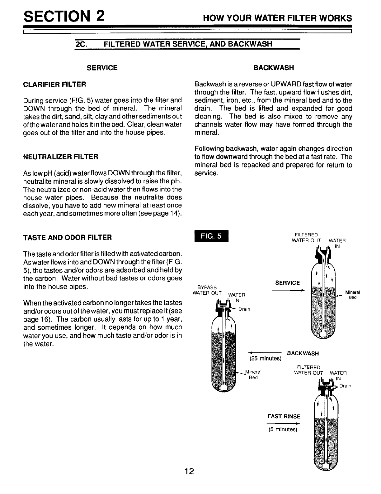
During service (FIG. 5) water goes into the filter and
DOWN through the bed of mineral. The mineral
takes the dirt, sand, silt, clay and other sediments out
of the water and holds it in the bed. Clear, clean water
goes out of the filter and into the house pipes.
NEUTRALIZER FILTER
As low pH (acid) water flows DOWN through the filter,
neutralite mineral is slowly dissolved to raise the pH.
The neutralized or non-acid water then flows into the
house water pipes. Because the neutralite does
dissolve, you have to add new mineral at least once
each year, and sometimes more often (see page 14).
BACKWASH
Backwash is a reverse or UPWARD fast flow of water
through the filter. The fast, upward flow flushes dirt,
sediment, iron, etc., from the mineral bed and to the
drain. The bed is lifted and expanded for good
cleaning. The bed is also mixed to remove any
channels water flow may have formed through the
mineral.
Following backwash, water again changes direction
to flow downward through the bed at a fast rate. The
mineral bed is repacked and prepared for return to
service.
TASTE AND ODOR FILTER
The taste and odor filter is filled with activated carbon.
As water flows into and DOWN through the filter (FIG.
5), the tastes and/or odors are adsorbed and held by
the carbon. Water without bad tastes or odors goes
into the house pipes.
When the activated carbon no longer takes the tastes
and/or odors out of the water, you must replace it (see
page 16). The carbon usually lasts for up to 1 year,
and sometimes longer. It depends on how much
water you use, and how much taste and/or odor is in
the water.
BYPASS
WATER OUT WATER
IN
Drain
FILTERED
WATER OUT
SERVICE
l=
qBACKWASH
(25 minutes)
FILTERED
Mineral WATER OUT
Bed
WATER
IN
WATER
IN
.Drain
Mineral
Bed
FAST RINSE
Ji
(5 minutes)
12
SECTION 3 CAR,:OFYOURR,TER
I
3A. KEEP THE FILTER FROM FREEZING
If the filter is installed where it could freeze (summer
cabin, lake home, etc.), you must drain all water
from it to stop possible freeze damage. To drain the
filter --
•
=
=
m
5.
Close the shut-off valve on the house main water
pipe, near the water meter or pressure tank.
Open a faucet in the filtered water pipes to vent
pressure in the filter.
Looking at FIG. 8 on page 18, move the stem in
a single bypass valve to bypass. Close the inlet
and outlet valve in a 3-valve bypass system, and
open the bypass valve.
Unplug the transformer at the wall outlet.
Pull the holding clip to remove the drain fitting,
n
=
am
with drain hose attached, from the valve. DO
NOT LOSE THE BLACK RUBBER FLOW PLUG
AND RETAINER.
Remove the plastic clips (see key #41, page 26)
and pull the adaptors or bypass valve from the
inlet and outlet.
Move the filter close to the floor drain. SLOWLY
and CAREFULLY (the filter is heavy) tip the filter
over so the valve inlet and outlet are over the
drain. Allow water to drain from tank. DO NOT
REST THE FILTER ON THE INLET AND OUT-
LET FITTINGS OR THEY WILL BREAK.
Tip the bottom of the filter up a few inches and
hold until all water has drained. Leave th_ filter
laving like this until you are ready to use it. Plug
the inlet and outlet with rags to keep dirt, bugs,
etc. out.
13
SECTION 3 CARE OF YOUR FILTER
I
3B. ADDING MINERAL..
I
• NEUTRALIZER FILTER
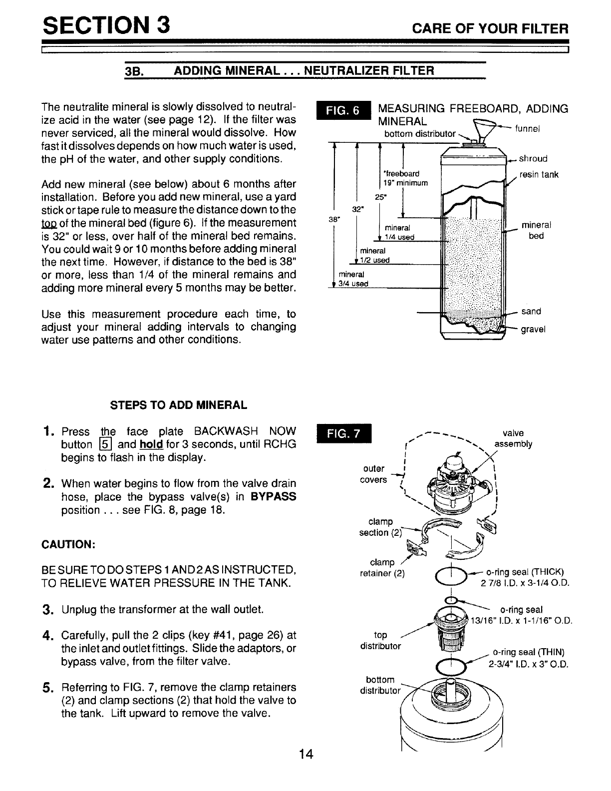
The neutralite mineral is slowly dissolved to neutral-
ize acid in the water (see page 12). If the filter was
never serviced, all the mineral would dissolve. How
fast it dissolves depends on how much water is used,
the pH of the water, and other supply conditions.
Add new mineral (see below) about 6 months after
installation. Before you add new mineral, use a yard
stick or tape rule to measure the distance down to the
of the mineral bed (figure 6). If the measurement
is 32" or less, over half of the mineral bed remains.
You could wait 9 or 10 months before adding mineral
the next time. However, if distance to the bed is 38"
or more, less than 1/4 of the mineral remains and
adding more mineral every 5 months may be better.
Use this measurement procedure each time, to
adjust your mineral adding intervals to changing
water use patterns and other conditions.
l [ ",
* " ' rn
mineral
3/4 used
_:_;_i_3! .....
MEASURING FREEBOARD, ADDING
MINERAL _-----_,_...
bottom distributor _' funnel
_ shroud
/resin tank
mineral
bed
...- sand
gravel
STEPS TO ADD MINERAL
1. Press the face plate BACKWASH NOW
button [] and hold for 3 seconds, until RCHG
begins to flash in the display.
2. When water begins to flow from the valve drain
hose, place the bypass valve(s) in BYPASS
position.., see FIG. 8, page 18.
CAUTION:
BE SURE TO DO STEPS 1AND2 AS INSTRUCTED,
TO RELIEVE WATER PRESSURE IN THE TANK.
3. Unplug the transformer at the wall outlet.
4. Carefully, pull the 2 clips (key #41, page 26) at
the inlet and outlet fittings. Slide the adaptors, or
bypass valve, from the filter valve.
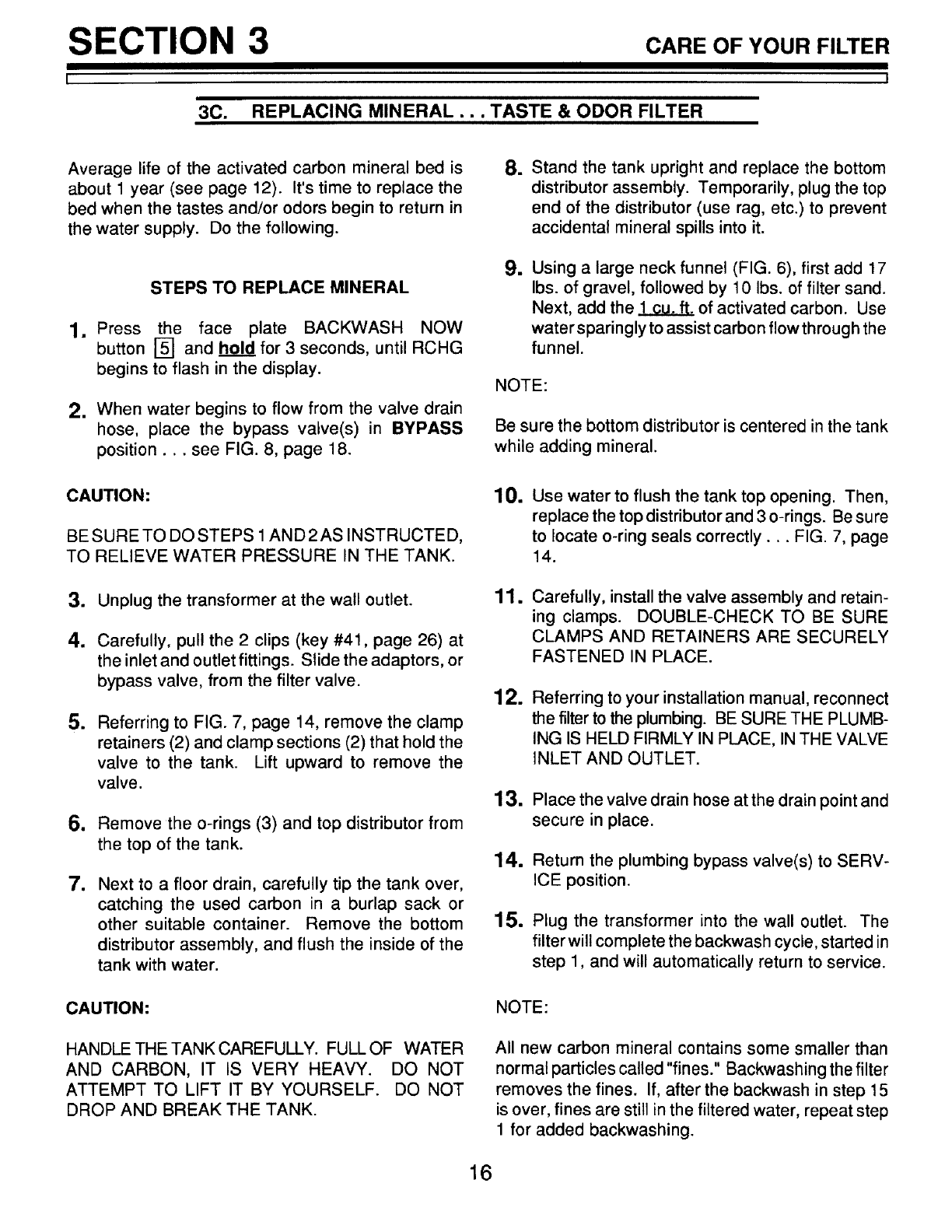
5. Referring to FIG. 7, remove the clamp retainers
(2) and clamp sections (2) that hold the valve to
the tank. Lift upward to remove the valve.
14

SECTION 3 CARE OF YOUR FILTER
I
3B.
I
ADDING MINERAL... NEUTRALIZER FILTER
6. Remove the o-rings (3) and top distributor from
the top of the tank.
7. To make room for the new mineral, use a hose to
siphon water from the tank.
8. Using a large neck funnel, add new mineral into
the tank.
IMPORTANT:
DO NOT ADD MINERAL INTO THE Bo'n'OM
DISTRIBUTOR. Temporarily plug the distributor
tube to prevent accidental mineral spills into it.
DO NOT OVERFILL the tank. Freeboard area (see
FIG. 6) is needed for proper backwashing. If you
have mineral remaining, you can use it the next
time you refill the tank.
9. Use water to flush the tank top opening. Then,
replace the top distributor and 3 o-rings. Be sure
to locate o-ring seals correctly... FIG. 7.
10. Carefully, install the valve assembly and retain-
ing clamps. DOUBLE-CHECK TO BE SURE
CLAMPS AND RETAINERS ARE SECURELY
FASTENED IN PLACE.
11. Referring to your installation manual, reconnect
the filter tothe plumbing. BE SURE THE PLUMB-
ING IS HELD FIRMLY IN PLACE, IN THE VALVE
INLET AND OUTLET.
12. Place the valve drain hose at the drain point and
secure in place.
13. Return the plumbing bypass valve(s) to SERV-
ICE position.
14. Plug the transformer into the wall outlet. The
filter will complete the backwash cycle, started in
step 1, and will automatically return to service.
15
SECTION 3 CAREOFYOURFILTER
[ I
3C. REPLACING MINERAL... TASTE & ODOR FILTER
Average life of the activated carbon mineral bed is
about 1 year (see page 12). It's time to replace the
bed when the tastes and/or odors begin to return in
the water supply. Do the following.
STEPS TO REPLACE MINERAL
=
=
Press the face plate BACKWASH NOW
button [] and hold for 3 seconds, until RCHG
begins to flash in the display.
When water begins to flow from the valve drain
hose, place the bypass valve(s) in BYPASS
position.., see FIG. 8, page 18.
CAUTION:
BE SURE TO DO STEPS 1AND2AS INSTRUCTED,
TO RELIEVE WATER PRESSURE IN THE TANK.
=
4.
=
Unplug the transformer at the wall outlet.
Carefully, pull the 2 clips (key #41, page 26) at
the inlet and outlet fittings. Slide the adaptors, or
bypass valve, from the filter valve.
Referring to FIG. 7, page 14, remove the clamp
retainers (2) and clamp sections (2) that hold the
valve to the tank. Lift upward to remove the
valve.
g
=
Remove the o-rings (3) and top distributor from
the top of the tank.
Next to a floor drain, carefully tip the tank over,
catching the used carbon in a burlap sack or
other suitable container. Remove the bottom
distributor assembly, and flush the inside of the
tank with water.
.Stand the tank upright and replace the bottom
distributor assembly. Temporarily, plug the top
end of the distributor (use rag, etc.) to prevent
accidental mineral spills into it.
1Using a large neck funnel (FIG. 6), first add 17
Ibs. of gravel, followed by 10 Ibs. of filter sand.
Next, add the 1 cu. ft. of activated carbon. Use
water sparingly to assist carbon flowthrough the
funnel.
NOTE:
Be sure the bottom distributor is centered in the tank
while adding mineral.
10.
11.
12.
13.
14.
15.
Use water to flush the tank top opening. Then,
replace the top distributor and 3 o-rings. Be sure
to locate o-ring seals correctly... FIG. 7, page
14.
Carefully, install the valve assembly and retain-
ing clamps. DOUBLE-CHECK TO BE SURE
CLAMPS AND RETAINERS ARE SECURELY
FASTENED IN PLACE.
Referring to your installation manual, reconnect
the filter to the plumbing. BE SURE THE PLUMB-
ING IS HELD FIRMLY IN PLACE, IN THE VALVE
INLET AND OUTLET.
Place the valve drain hose at the drain point and
secure in place.
Return the plumbing bypass valve(s) to SERV-
ICE position.
Plug the transformer into the wall outlet. The
filter will complete the backwash cycle, started in
step 1, and will automatically return to service.
CAUTION:
HANDLE THE TANK CAREFULLY. FULL OF WATER
AND CARBON, IT IS VERY HEAVY. DO NOT
ATTEMPT TO LIFT IT BY YOURSELF. DO NOT
DROP AND BREAK THE TANK.
NOTE:
All new carbon mineral contains some smaller than
normal particles called "fines." Backwashing the filter
removes the fines. If, after the backwash in step 15
is over, fines are still in the filtered water, repeat step
1 for added backwashing.
16
SECTION 3 CARE OF YOUR FILTER
I I
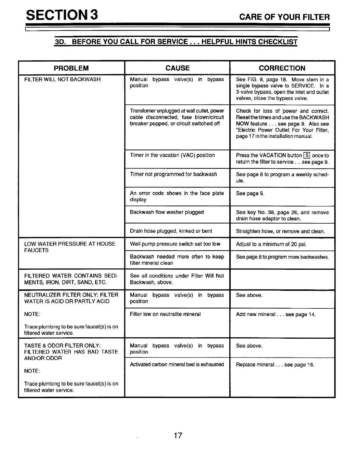
3D. BEFORE YOU CALL FOR SERVICE . . . HELPFUL HINTS CHECKLIST
PROBLEM
FILTER WILL NOT BACKWASH
LOW WATER PRESSURE AT HOUSE
FAUCETS
FILTERED WATER CONTAINS SEDI-
MENTS, IRON, DIRT, SAND, ETC.
NEUTRALIZER FILTER ONLY: FILTER
WATER IS ACID OR PARTLY ACID
NOTE:
Trace plumbing to be sure faucet(s) is on
filtered water service.
TASTE & ODOR FILTER ONLY:
FILTERED WATER HAS BAD TASTE
AND/OR ODOR
NOTE:
Trace plumbing to be sure faucet(s) is on
filtered water service.
CAUSE
Manual bypass valve(s) in bypass
position
Transfomer unplugged at wall outlet, power
cable disconnected, fuse blown/cimuit
breaker popped, or circuit switched off
CORRECTION
See FIG. 8, page 18. Move stem in a
single bypass valve to SERVICE. In a
3-valve bypass, open the inlet and outlet
valves, close the bypass valve.
Check for loss of power and correct.
Reset the times and use the BACKWASH
NOW feature.., see page 9. Also see
"Electric Power Outlet For Your Filter,
page 17 in the installation manual.
Timer in the vacation (VAC) positFon Press the VACATION button [] once to
return the filter to service.., see page 9.
Timer not programmed for backwash See page 8 to program a weekly sched-
ule.
An error code shows in the face plate See page 9.
display
Backwash flow washer plugged
Drain hose plugged, kinked or bent
Well pump pressure switch set too low
Backwash needed more often to keep
tilter mineral clean
See all conditions under Filter Will Not
Backwash,above.
Manual bypass valve(s) in bypass
position
Filter low on neutralite mineral
Manual bypass valve(s) in bypass
position
Activated carbon mineral bed is exhausted
See key No. 38, page 26, and remove
drain hose adaptor to clean.
Straighten hose, or remove and clean.
Adjust to a minimum of 20 psi.
See page 8 to program more backwashes.
See above.
Add new mineral.., see page 14.
See above.
Replace mineral.., see page 16.
17

SECTION 4 OTHERTHI.GSTOK.OW
I
4A.
I
DIMENSIONS/SPECIFICATIONS
BYPASS VALVES
SINGLE-PLASTIC
PULL STEM
OUTWARD
FOR
SERVICE
Push
Inward
For
Bypass
3-VALVE
SERVICE
Close Bypass Valve
Open Inlet & Outlet Valves
BYPAS_
Open Bypass Valve
Close Inlet & Outlet Valves
II IIjBypass
Outlet__ Valve
Vat_e',_ (_! .,let
._Jl _ Valve
55"
139.6 cm
--2711"-...
DIA.
.9 cm
Inlet-Outlet
49"
124.5 cm
Mineral Tank Nominal Size: 10" dia. x 47" high
TYPE OF FILTERING MINERAL
AMOUNT OF FILTERING MINERAL
WATER PRESS. LIMITS (Min.-Max.)
MAXIMUM WATER TEMPERATURE
MINIMUM WELL PUMP CAPACITY
MIN. PIPE SIZE TO FILTER
BACKWASH FLOW RATE*
SERVICE FLOW RATE/CAPACITY
* At 35 psi inlet water pressure
CLARIFIER
625.348234
Aggregate
NEUTRALIZER TASTE & ODOR
625.348241 625.348251
Neutralite Activated Carbon
1.0 Cu. Ft. (,028 Cu M)
20 to 125 PSI (1.4 to 8.4 KG/Sq/Cm)
120 F (48.9 C)
270 Gal/Hr (1022 Liter/Hr)
3/4 In. (19MM)
4.5 Gal/Min (17 Liter/Min)
See Rating Decal on Filter
18
SECTION 5
[
5A.
SERVICER'S TECH. INFORMATION
]
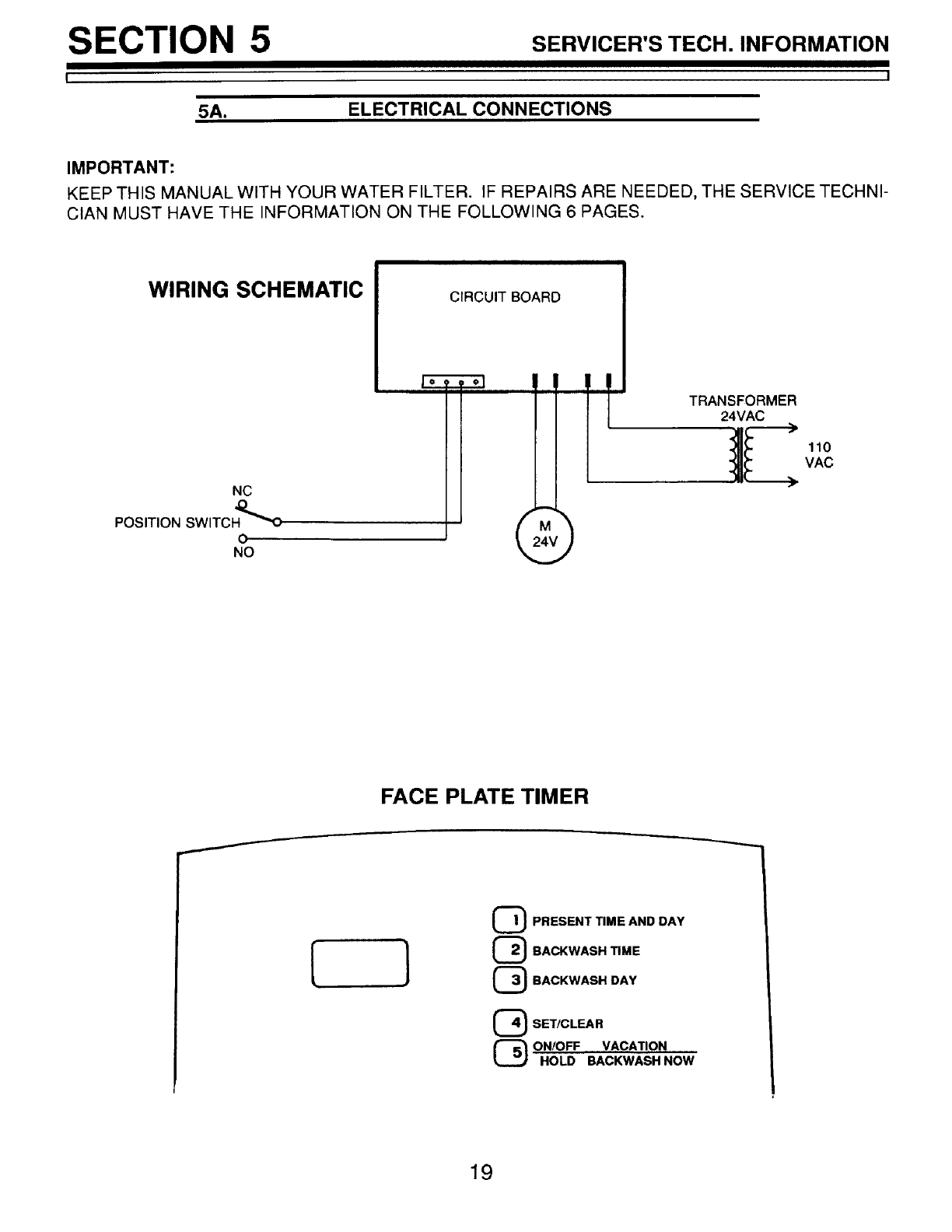
ELECTRICAL CONNECTIONS
IMPORTANT:
KEEP THIS MANUAL WITH YOUR WATER FILTER. IF REPAIRS ARE NEEDED, THE SERVICE TECHNI-
CIAN MUST HAVE THE INFORMATION ON THE FOLLOWING 6 PAGES,
WIRING SCHEMATIC CIRCUIT BOARD
NC
POSITION SWITC H"O_'_O
o
NO
M
110
VAC
FACE PLATE TIMER
I
{ } QPRESENT TIME AND DAY
{_ BACKWASH TIME
(_ BACKWASH DAY
_) SET/CLEAR
(_ ON/OFF VACATION
HOLD BACKWASH NOW
19
SECTION 5 SERVICER'STECH. INFORMATION
I I
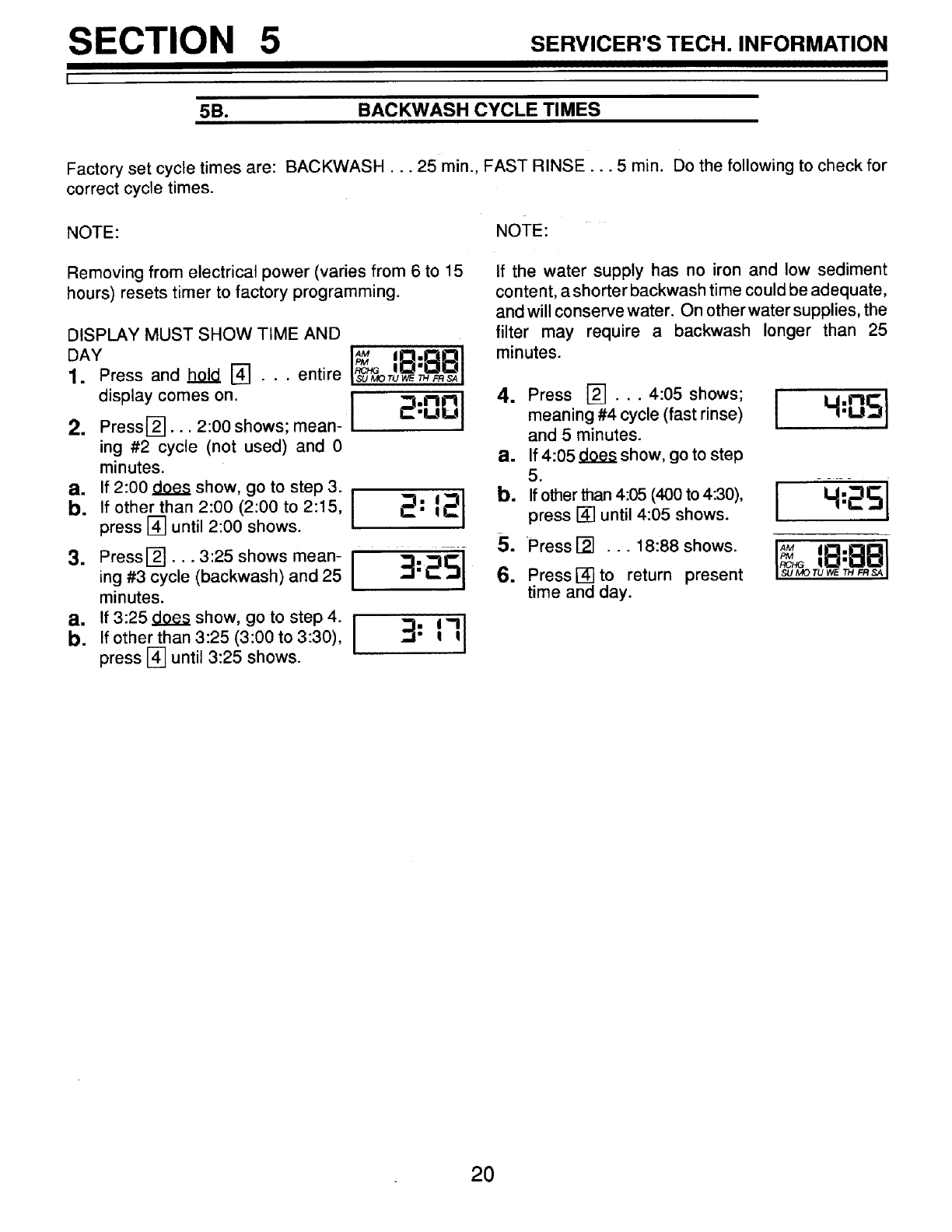
5B. BACKWASH CYCLE TIMES
Factory set cycle times are: BACKWASH... 25 min., FAST RINSE... 5 min. Do the following to check for
correct cycle times.
NOTE: NOTE:
Removing from electrical power (varies from 6 to 15
hours) resets timer to factory programming.
DISPLAY MUST SHOW TIME AND
1. Press and hold [] . . . entire
display comes on.
2. Press_]...2:00shows;mean-[ _:_J
ing #2 cycle (not used) and 0
minutes.
• If other than 2:00 (2:00 to 2:15, _"
press [] until 2:00 shows.
3. Pressl_... 3:25 shows mean- I :_ :_Cl--
ing #3 cycle (backwash)and 25 I ""-I"-I_ "11
minutes.
P3" If 3:25 does show, gotostep4. [ !
• If other than 3:25 (3:00 to 3:30), 3:17
press [] until 3:25 shows.
If the water supply has no iron and low sediment
content, a shorter backwash time could be adequate,
and will conserve water. On otherwater supplies, the
filter may require a backwash longer than 25
minutes.
4. Press [_... 4:05 shows; D£J
meaning #4 cycle (fast rinse) 1.1,
and 5 minutes.
a. If 4:05 does show, go to step
5.
b. Ifotherthan4:05(400to4:30), 1_=_5 [
press [] until 4:05 shows.
5. Press [] ... 18:88 shows. I_
IRCHG
6. Press i-4-1to return present SU_TUW_T,_SA
time and day.
2O

SECTION 5
50.
SERVICER'S TECH. INFORMATION
I
DIAGNOSTICS
AUTOMATIC ELECTRONIC DIAGNOSTICS
The face plate has a self-diagnostic function for the
electrical system (except input power). The face plate
monitors the electronic components and circuits for
correct operation. If a malfunc- I ]
tion occurs, an error code ap- E- 3
pears in the face plate display.
The chart below shows the error codes that could
appear, and the possible defects for each code.
While an error code appears in the display, all face
plate buttons are inoperable except the SET/CLEAR
button. SET/CLEAR remains operational so the
service person can make the MANUAL ADVANCE
DIAGNOSTICS to further isolate the defect.
CODE
E-1
E-2, E-3
E-4
POSSIBLE DEFECT
MOST LIKELY = =" LESS LIKELY
motor inop. /wiring harness or connection to switch /switch /face plate
face plate
face plate /position switch
PROCEDURE FOR REMOVING ERROR CODE FROM FACE PLATE: 1. Unplug transformer 2. Correct
defect 3. Plug-in transformer 4. Wait for 6minutes. The error code will return if the defect was not corrected.
MANUAL ADVANCE DIAGNOSTIC
Use the following procedures to advance filter valve
through recharge cycles to check operation.
Remove top cover to observe valve rotation.
DISPLAY MUST SHOW TIME AND DAY
1. Press and hol_ll_] for3 seconds
until 18:88 displays.
2. Press [] to display position (P)
switch open or closed indicator.
If valve is in service, backwash or fast
rinse (see markings on cam under mo-
tor), display will show... (--), meaning
the position switch is open.
While the valve is rotating from
one cycle to another, the display
shows (-P), meaning the posi-
tion switch is closed.
M
NOTE:
While in manual advance, the time display automati-
cally returns to the present time of day if a button is not
pressed within 4 minutes.
=To advance valve, pressi5]each time you want to
move into next cycle. (Pressing [] while valve is
rotating has no affect.)
-- Press []to move filter into back- I-PI
wash. Look for a fast flow of water l - - I
from drain hoses.
A slow flow indicates an obstructed top distribu-
tor, backwash flow plug, drain hose, or iron fouled
mineral bed.
=
5.
-- Press [] to move filter into fast
rinse. Again look for fast drain flow. I - PI
-- To return filter to service, press[5--]. _- -- J
Press [] to display 18:88.
Press [] to return present time and i. _ 3:H5 I
day.
21
SECTION 5SERVICER'S TECH. INFORMATION
5D.
I
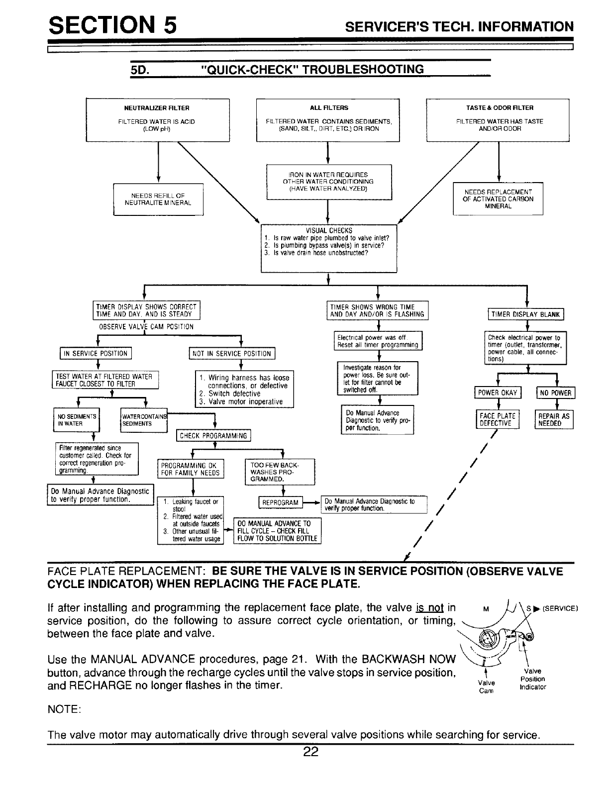
"QUICK-CHECK" TROUBLESHOOTING
NEUTRAUZER RLTER
FILTERED WATER IS ACID
(LOW phi
NEEDS REFILL OF
NEUTRALITE MINERAL
ALL RLTERS
FILTERED WATER CONTAINS SEDIMENTS,
(SAND, SILT,, DIRT, ETC.) OR IRON
1I
IRON IN WATER REQUIRES 1
OTHER WATER CONDITIONING I
(HAVE WATER ANALYZED)
VISUAL CHECKS
1. Is raw water pipe plumbed to valve inlet?
2. Is pumbing bypassvalve(s) in service?
3. Is valve brain hose unobstructed?
I ! TASTE & ODOR RLTER
FILTERED WATER HAS TASTE
AND/OR ODOR
NEEDS REPLACEMENT
OF ACTIVATED CAR_?,QN
MINERAL
[
ITIMER DISPLAY SHOWS CORRECTTIME AND DAY, AND IS STEADY
w
OBSERVE VALVE CAM POSITION
[
I,.SERVICEROS,T,DNI
TESTWATERAT FILTEREDWATER
FAUCETCLOSESTTO FILTER
t
f f 1
Fitterregeneratebsince
customersailed. Check for
correctregenerationpro-
gramming.
INOTI.BERV,CEPOS_T,0NI
1. Wiring harness has loose/
connections, or defective J
2. Switch defective
[3. Vave motor noperal ve
IC.EC.PROGRAMMI.GI
f
f t
PROGRAMMINGOK I TOO FEW BACK-
FOR FAMILY NEEDS t WASHES PRO-
GRAMMED.
TIMER SHOWS WRONGTIMEAND DAY AND/OR IS FLASHING
Electrical power was off
Reset a imer programming
f
I nvestigate reason for I
powerloss. Be sure out-
let for tilter cannot be
switched off.f
Do ManualAdvance
Diagnostic to redly pro-
per function.
I
1!
1TtMERDISPLAY_._1
Check electrical power to
timer (outlet, transformer,
power cable, all connec-
tions t
I_OWEROKAYI
DEFECTIVE I
7
/
/
/
IooManoa'A°vance°iao°°st'cl /
to verily proper function. 1 Leakingfaucet or REPROGRAM_ Do ManualAdvanceDiagnostic to
stool I ' --I verify properfunction. 1 /
2, Filteredwater usedl
at outside faucets I I D0 MANUALADVANCETO i/
3. Other unusual til- r-=-i FILL CYCLE-CHECKFILL I
totedwater usageJ I FLOWTO SOLUTIONBOTTLEI /
/
FACE PLATE REPLACEMENT: BE SURE THE VALVE IS IN SERVICE POSITION (OBSERVE VALVE
CYCLE INDICATOR) WHEN REPLACING THE FACE PLATE.
If after installing and programming the replacement face plate, the valve isnot in M
service position, do the following to assure correct cycle orientation, or timing,
between the face plate and valve. ",_
S I_ (SERVICE)
Use the MANUAL ADVANCE procedures, page 21. With the BACKWASH NOW
button, advance through the recharge cycles until the valve stops in service position, l Valve
Position
and RECHARGE no longer flashes in the timer, valve
Cam Indicator
NOTE:
The valve motor may automatically drive through several valve positions while searching for service.
22

SECTION 5
5E.
SERVICER'S TECH. INFORMATION
I
ROTARY VALVE SERVICE
BEFORE WORKING ON THE VALVE, TURN OFF
THE WATER SUPPLY AND DISCONNECT FROM
ELECTRICAL POWER, TO RELIEVE PRESSURE...
... 3 VALVE BYPASS: Close the inlet valve and open
a filtered water faucet. Then close the outlet valve
and open the bypass valve.
... SEARS SPECIAL BYPASS: Slide the bypass
valve stem to bypass position. Loosen the 3 hex
head screws (see(_)in drawing) toward the backside
of the valve to allow pressure water to bleed out
(catch water with a rag).
DISASSEMBLY
To remove a part or group of parts, refer to the valve
drawing. A common screwdriver or nut driver, Phil-
lips screwdriver and pliers are the only tools needed
to completely disassemble.
SERVICING THE VALVE
Inspect all o-rings, seals and gaskets for wear or
defects.
Inspect the bottom surface of the rotor and disc for
scratches, chips or wear.
NOTE:
If replacement is needed, be sure to use the current
replacement part.
ASSEMBLY
Be sure all parts are in place and in the proper
position. Lubricate ALL o-rings, and seals with FDA
approved silicone grease. To install the rotor seal,
first place the seal into the valve groove, rounded
side down (see cross-section). Apply a light coating
of silicone grease to the sears crossing ribs. Then,
carefully center the wear strip on the seal, and push
it downward onto the seal.
L. _alve cam
Ianndgear
retainer
washer
plate
\
flow plug (backwash
and fast rinse flow
rate control)
Install the nozzle and venturi seal and drain seal.
Assemble 2 o-rings and the wave washer onto the
rotor and disc. Then center the rotor and disc, in the
valve body, on the rotor seal.
Lower the cover onto the valve body and rotor shaft.
Then install the cover holding screws. BEFORE
TIGHTENING THE SCREWS, INSTALLTHE VALVE
CAM AND GEAR, THEN TURN THE ROTOR
(CLOCKWISE ONLY) TO SERVICE POSITION.
Tighten the screws using a criss-cross pattern. If a
torque wrench is available, torque to 30-40 inch
pounds.
Lubricate the gear on the motor, and the valve cam
gear with Molykote grease, or other high quality gear
lubricant.
Be sure to orient switch as shown, with lever toward
the valve cam.
23

SECTION 5 SERVICER'S TECH. INFORMATION
II
5F. WATER FLOW THROUGH THE FILTER VALVE
SERVICE CYCLE
POSITION
SWITCH
VALVE OUTLET'
(FILTERED WATER
,VALVE INLET
(UNFILTERED WATER)
TOP
DISTRIBUTOR
MINERAL
TANK
INERAt
BED •
DISTRIBUTOR
Hard, unfiltered water enters the valve inlet port. Internal valve
porting routes the water down and out the top distributor, into the
mineral tank. The water is filtered as it passes through the
mineral bed, then enters the bottom distributor. Filtered water
llows back into the valve and out the valve outlet, to the house
filtered water pipes.
ROTOR & DISC
\
BACKWASH CYCLE
PLUG
FAST RINSE CYCLE
ROTOR & DISC
POSITION SWITCH
)UTLET
INLET
DISTRIBUTOR OUTLET
DRAIN
INLET
TOP
DISTRIBUT(
BOTTOM
DISTRIBUTOR
POSITION
SWITCH
POSITION
SWITCH
:k,_ BOTTOM
DISTRIBUTOR
Timer/switch action allows the motor to turn the rotor & disc
to place the valve in BACKWASH. Water is routed down and
out the bottom distributor, upthrough the bed, and out the top
distributor to the drain. The fast flow (controlled by a flow plug
in the drain fitting) flushes dirt, sediments, and iron deposits
to the drain.
During FAST RINSE, the rotor & disc is positioned so water
flow enters the mineral tank through the top distributor, and
exits through the bottom distributor, to the drain. The fast flow
of water downward through the mineral bed flushes any re-
maining sediments to the drain. The mineral bed is packed and
prepared for return to service.
The solid state timer again energizes the motor to return the
valve to service. As the valve rotates, the position switch lever
drops to open the circuit. The valve remains positioned in ser-
vice until the timer initiates the next regeneration.
24
SECTION 6 REPAIRPARTS
I I
""_ 21
"_ 22//
_.. 2O
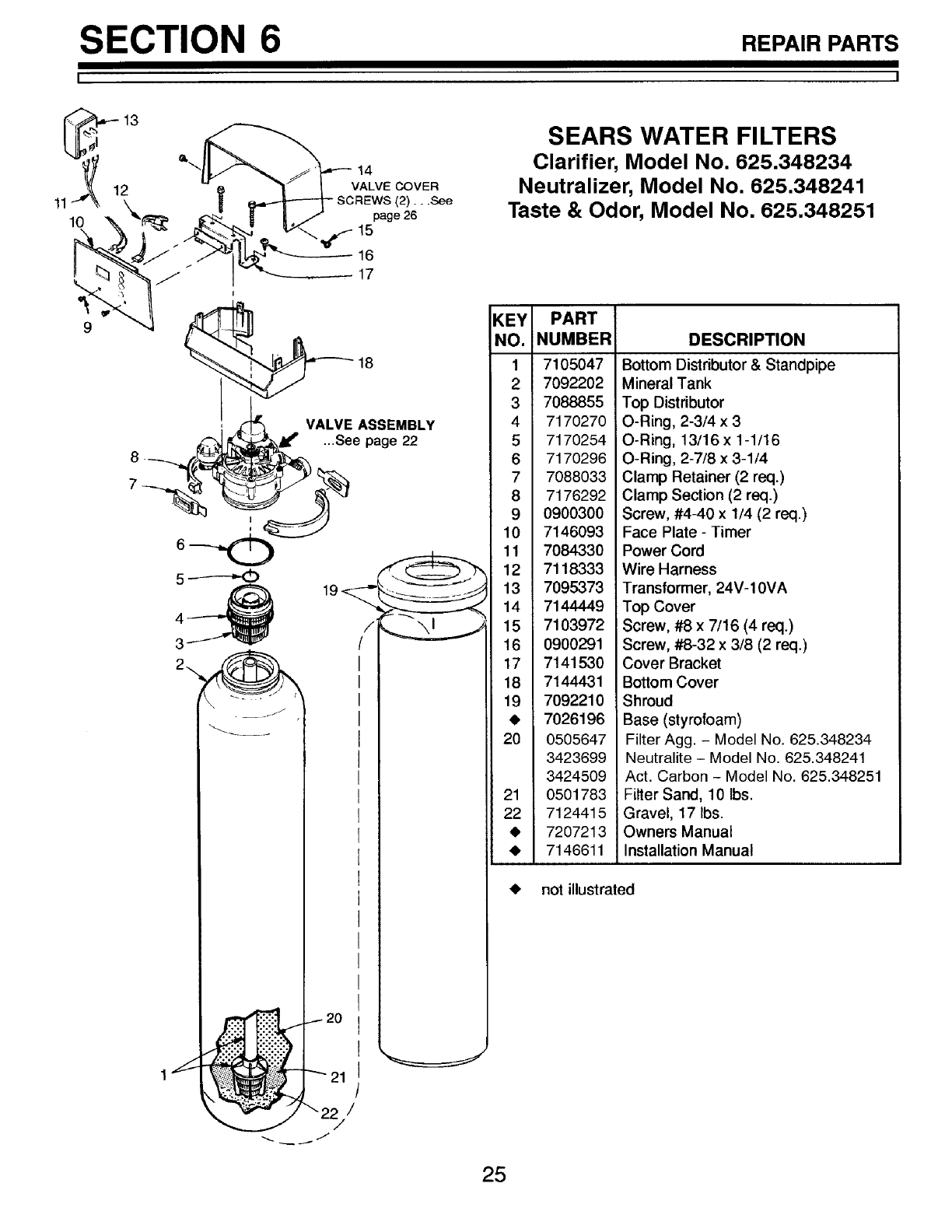
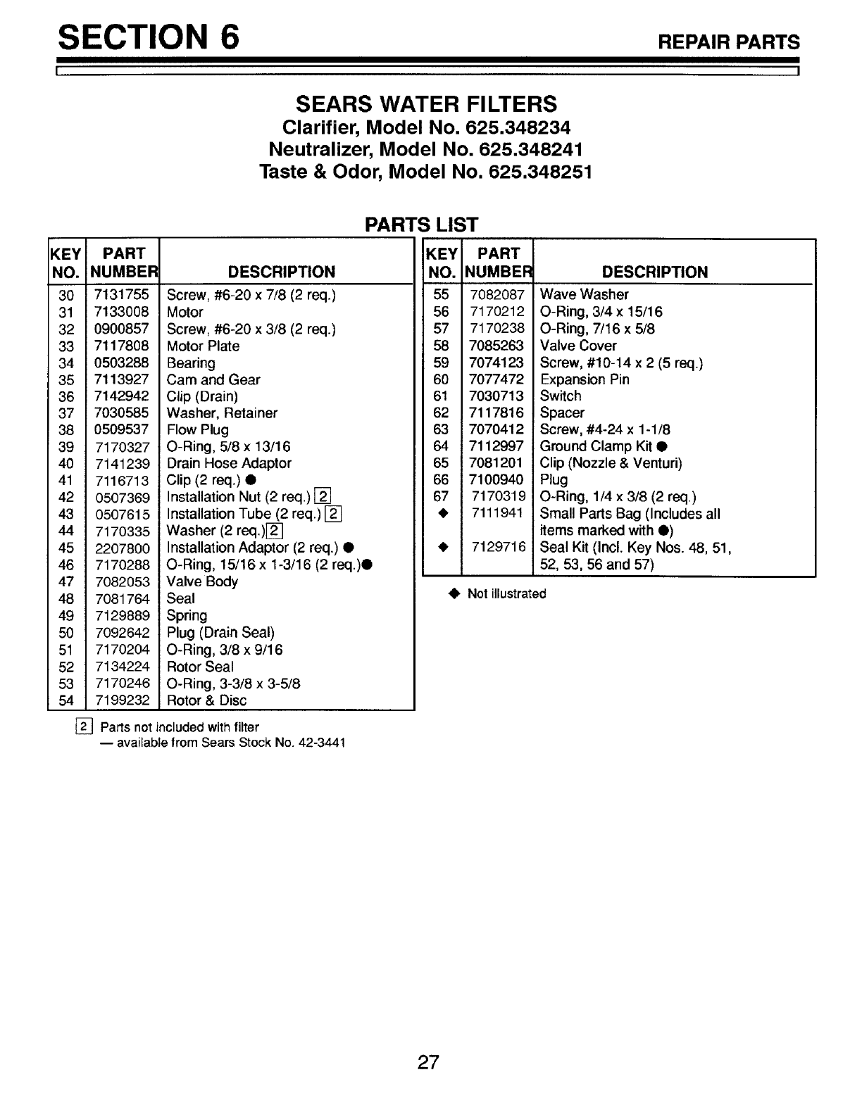
SEARS WATER FILTERS
Clarifier, Model No. 625.348234
Neutralizer, Model No. 625.348241
Taste & Odor, Model No. 625.348251
KEY PART
NO. NUMBER
1 7105047
2 7092202
3 7088855
4 7170270
5 7170254
6 7170296
7 7088033
8 7176292
90900300
10 7146093
11 7084330
12 7118333
13 7095373
14 7144449
15 7103972
16 0900291
17 7141530
18 7144431
19 7092210
7026196
20 0505647
3423699
3424509
21 0501783
22 7124415
41, 7207213
41, 7146611
DESCRIPTION
Bottom Distdbutor & Standpipe
Mineral Tank
Top Distributor
O-Ring, 2-3/4 x 3
O-Ring, 13/16 x 1-1/16
O-Ring, 2-7/8 x 3-1/4
Clamp Retainer (2 req.)
Clamp Section (2 req.)
Screw, #4-40 x 1/4 (2 req.)
Face Plate - Timer
Power Cord
Wire Harness
Transformer, 24V-10VA
Top Cover
Screw, #8 x 7/16 (4 req.)
Screw, #8-32 x 3/8 (2 req.)
Cover Bracket
Bottom Cover
Shroud
iBase (styrofoam)
Filter Agg. - Model No. 625.348234
Neutralite - Model No. 625.348241
Act. Carbon - Model No. 625.348251
Filter Sand, 10 Ibs.
Gravel, 17 Ibs.
Owners Manual
Installation Manual
_1, not illustrated
25
SECTION 6 REPAIRPARTS
II
63
62
58 _38 39 40
I
54
53
51
J
50
49
47
43
44
45
46
66
65
67
26
SECTION 6 REPAIRPARTS
I I
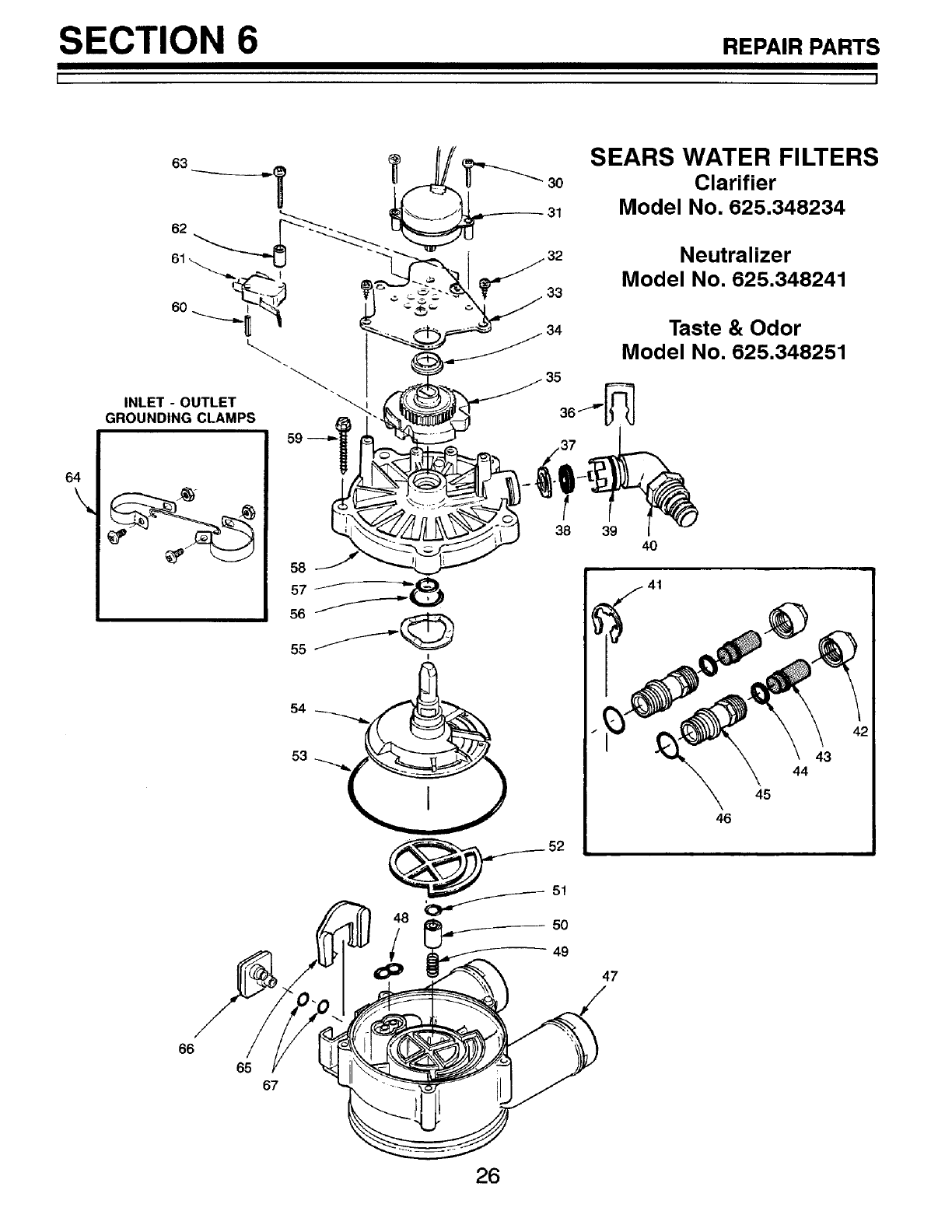
SEARS WATER FILTERS
Clarifier, Model No. 625.348234
Neutralizer, Model No. 625.348241
Taste & Odor, Model No. 625.348251
PARTS LIST
KEY PART
NO. NUMBER
3O 7131755
31 7133008
32 0900857
33 7117808
34 0503288
35 7113927
36 7142942
37 7030585
38 0509537
39 7170327
40 7141239
41 7116713
42 0507369
43 0507615
44 7170335
45 220780O
46 717O288
47 7082053
48 7081764
49 7129889
50 7O92642
51 717O204
52 7134224
53 7170246
54 7199232
[]
DESCRIPTION
Screw, #6-20 x 7/8 (2 req.)
Motor
Screw, #6-20 x 3/8 (2 reqo)
Motor Plate
Bearing
Cam and Gear
Clip (Drain)
Washer, Retainer
Flow Plug
O-Ring, 5/8 x 13/16
Drain Hose Adaptor
Clip (2 req.) •
Installation Nut (2 req.) []
Installation Tube (2 req.) []
Washer (2 req.)[_]
Installation Adaptor (2 req.) •
O-Ring, 15/16 x 1-3/16 (2 req.)•
Valve Body
Seal
Spring
Plug (Drain Seal)
O-Ring, 3/8 x 9/16
Rotor Seal
O-Ring, 3-3/8 x 3-5/8
Rotor & Disc
Parts not included with filter
-- available from Sears Stock No. 42-3441
KEY PART
NO. NUMBEF
55 7082087
56 7170212
57 7170238
58 7085263
59 7074123
60 7077472
61 7030713
62 7117816
63 7070412
64 7112997
65 7081201
66 7100940
67 717O319
• 7111941
• 7129716
•Not illustrated
DESCRIPTION
Wave Washer
O-Ring, 3/4 x 15/16
O-Ring, 7/16 x 5/8
Valve Cover
Screw, #10-14 x 2 (5 req.)
Expansion Pin
Switch
Spacer
Screw, #4-24 x 1-1/8
Ground Clamp Kit •
Clip (Nozzle & Venturi)
Plug
O-Ring, 1/4 x 3/8 (2 req)
Small Parts Bag (Includes all
items marked with •)
Seal Kit (Incl. Key Nos. 48, 51,
52, 53, 56 and 57)
27
_ARS
OWNER'S
MANUAL
MODEL NOS.
625.348234
Clarifier
625.348241
Neutralizer
625.348251
Taste & Odor
The model number of
your water filter is found
on the rating decal. This
decal is on the backside
of the top cover.
When requesting service
or ordering parts, always
provide the following in-
formation:
• Product Type
• Model Number
• Part Number
• Part Description
Kenmore
Water Filters
For the repair or replacement parts you need
delivered directly to your home
Call 7am - 7 pm, 7 days a week
1 - 800 - 366 - PART
(1 - 800 - 366 - 7278)
For in-home major brand repair service
Call 24 hours a day, 7 days a week
1 - 800 - 4 - REPAIR
(1 - 800 - 473 - 7247)
For the location of a
Sears Parts and Repair Center in your area
Call 24 hours a day, 7 days a week
1 - 800 - 488 - 1222
For information on purchasing a Sears
Maintenance Agreement, or to inquire
about an existing Agreement
Call 9 am - 5 pm, Monday - Saturday
1 - 800 - 827 - 6655
Sears, Roebuck and Co., Hoffman Estates, IL 60179 U.S.A.
7207213 (2/99)
