Seba Dynatronic Mess und Ortungstechnik LOGGSM3 Interface between the logger network and control centre User Manual part 2
Seba Dynatronic Mess- und Ortungstechnik GmbH Interface between the logger network and control centre part 2
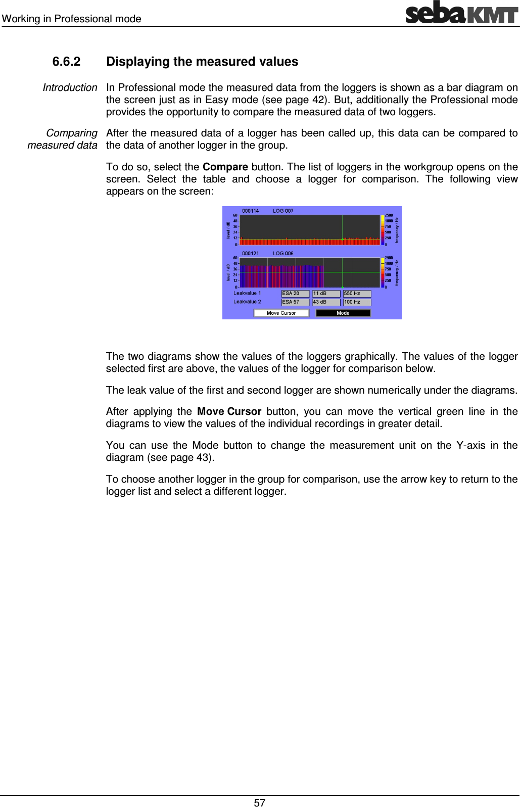
Contents
- 1. User manual part 1
- 2. User manual part 2
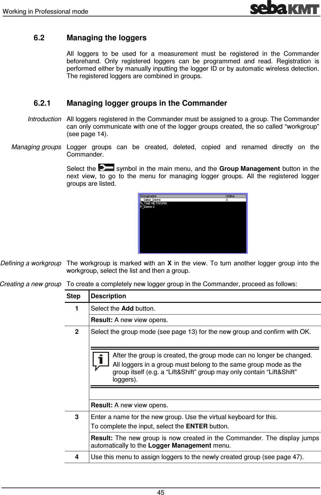
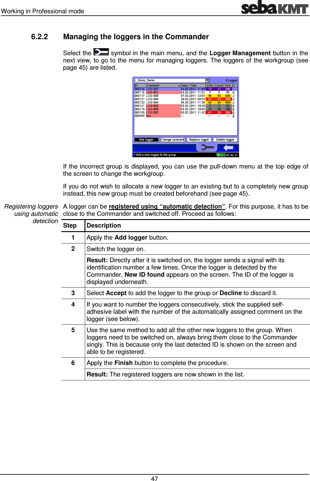
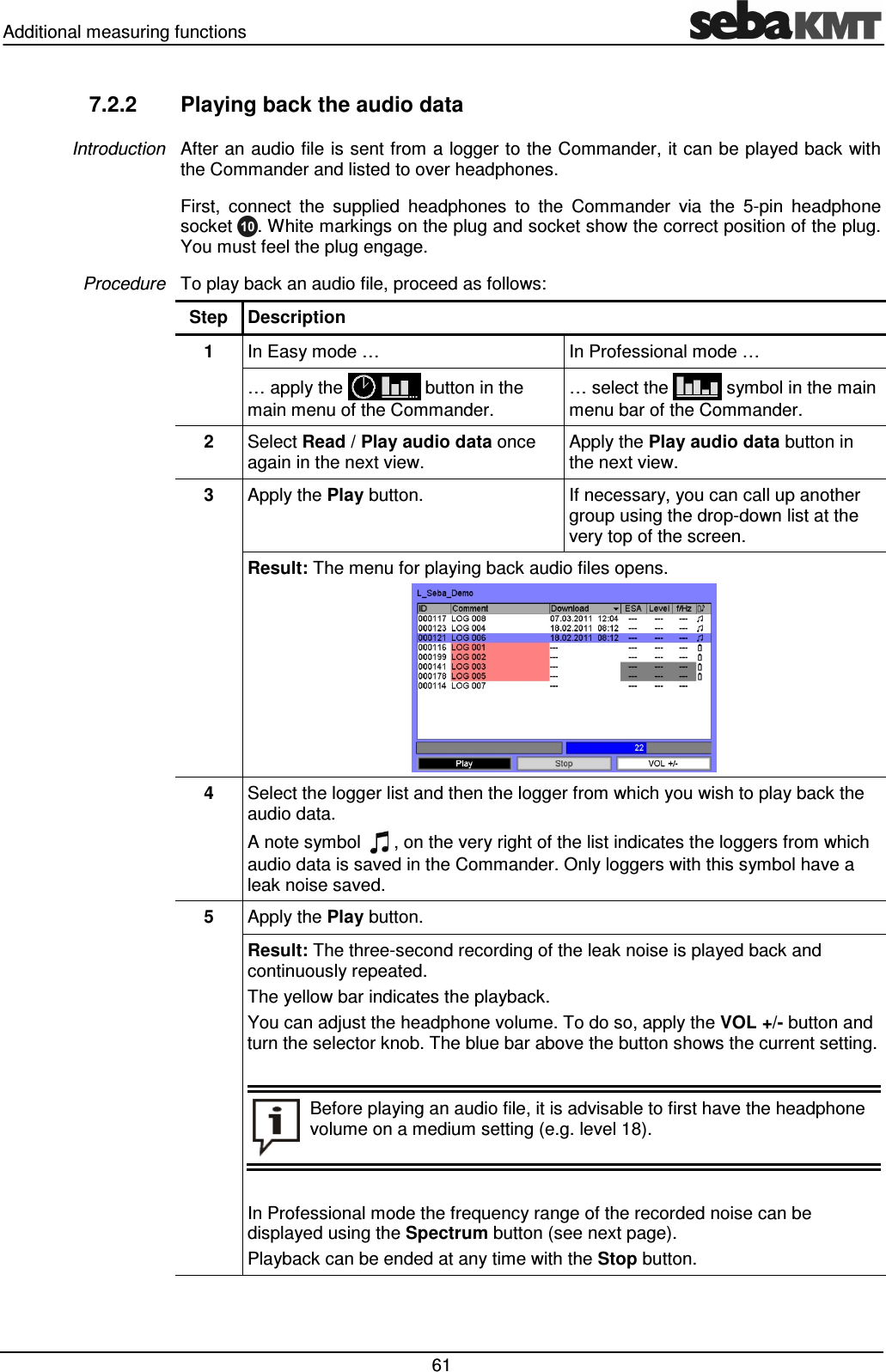
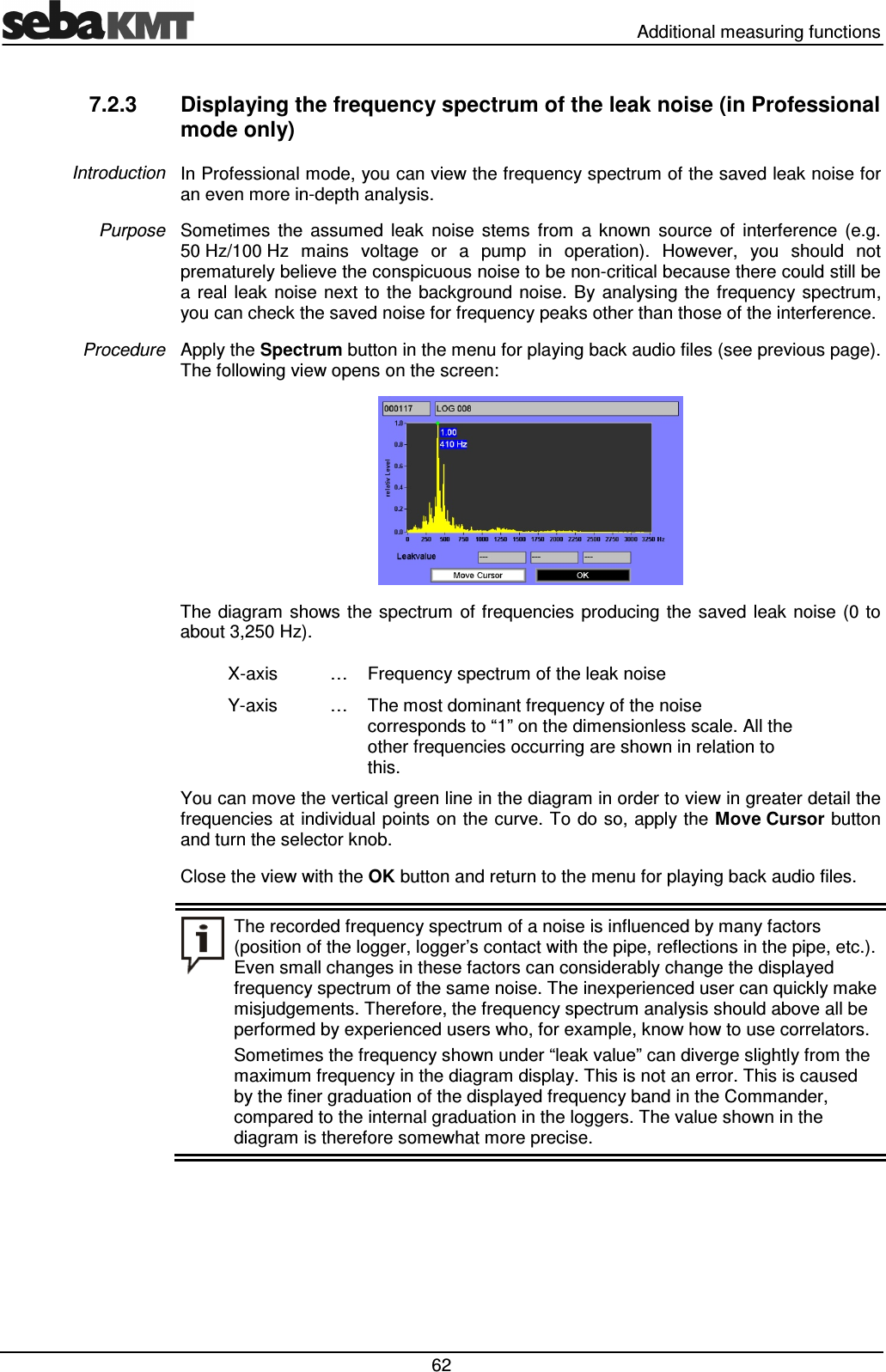
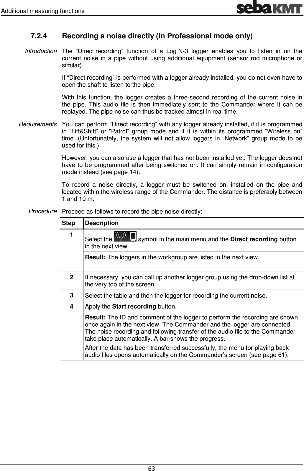
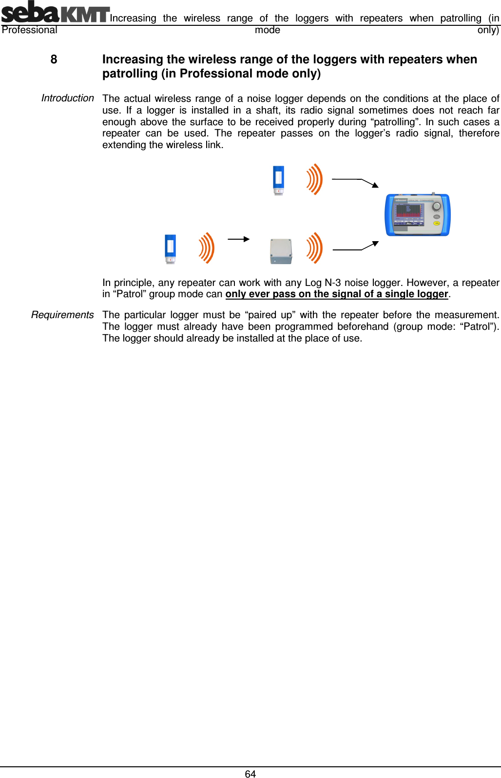
User manual part 2