Seba Dynatronic Mess und Ortungstechnik LOGRI Wireless Interface for Loggers and Repeaters User Manual part 1
Seba Dynatronic Mess- und Ortungstechnik GmbH Wireless Interface for Loggers and Repeaters part 1
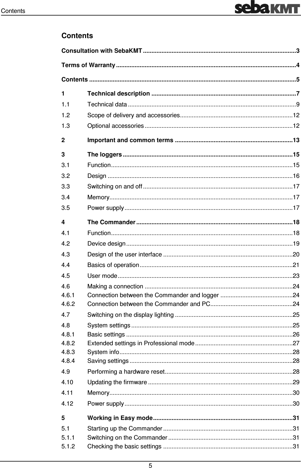
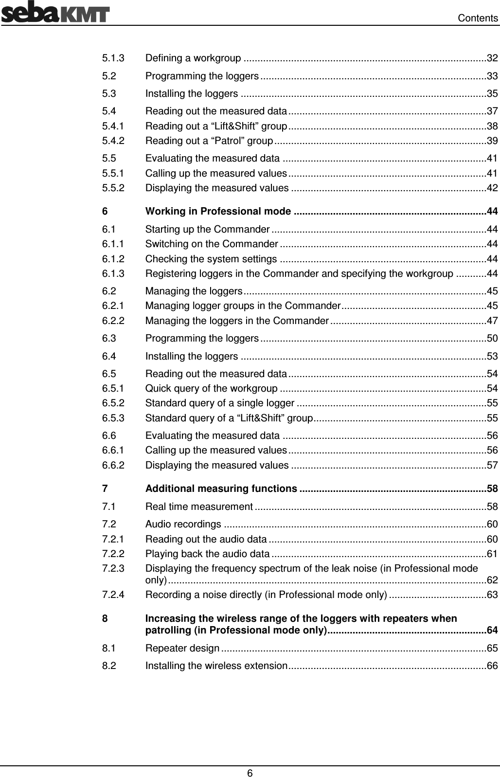
Contents
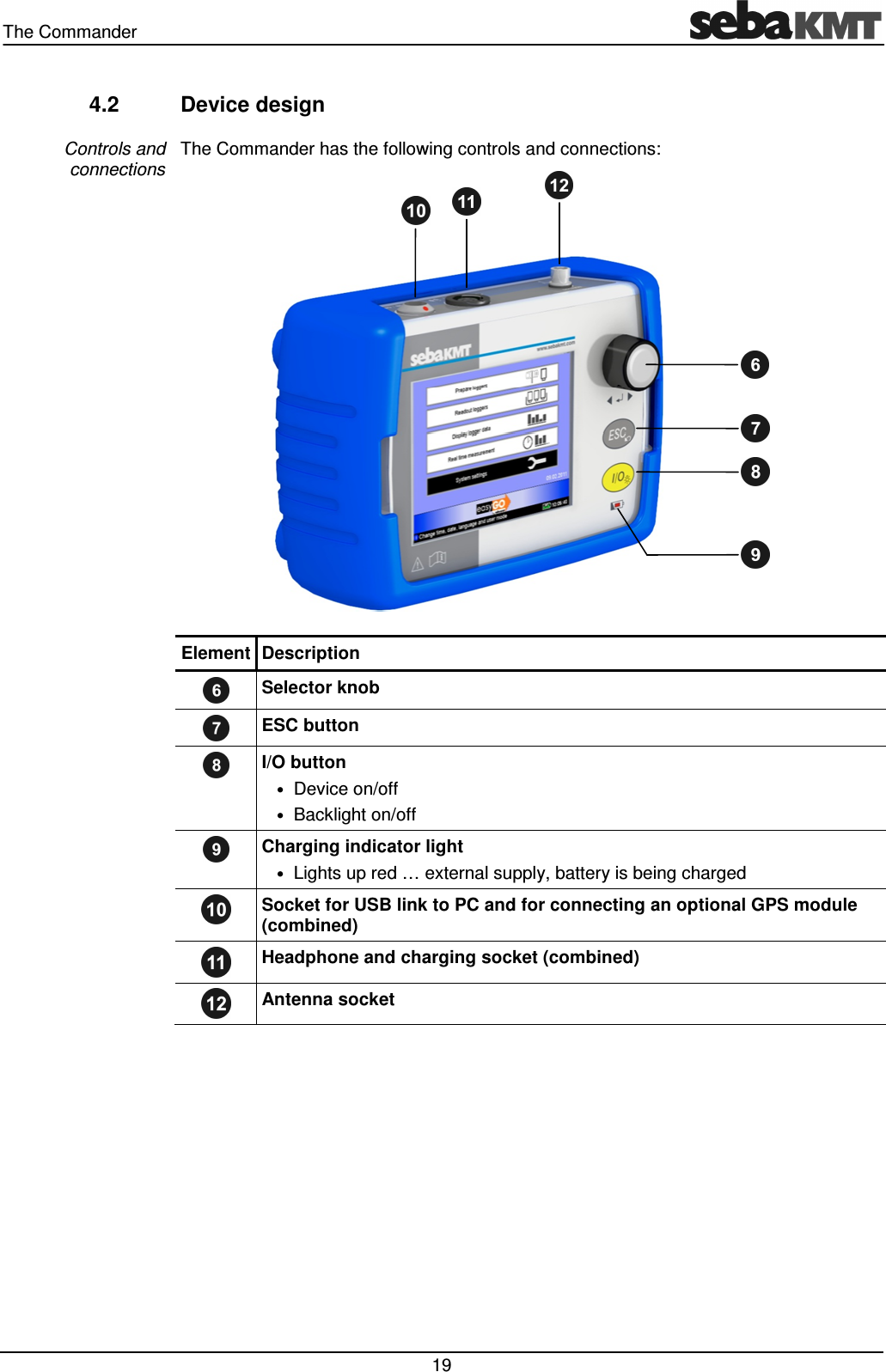
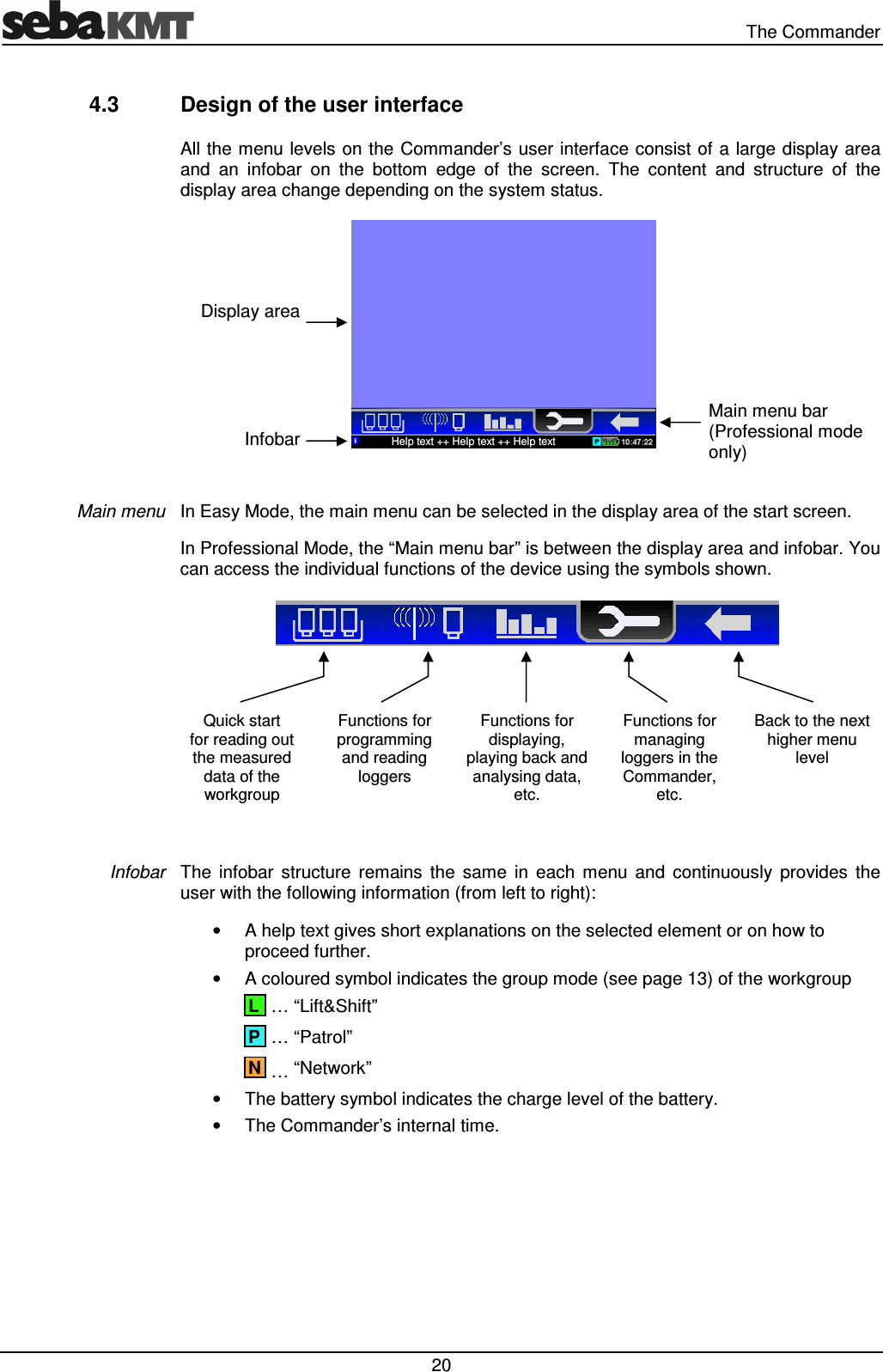
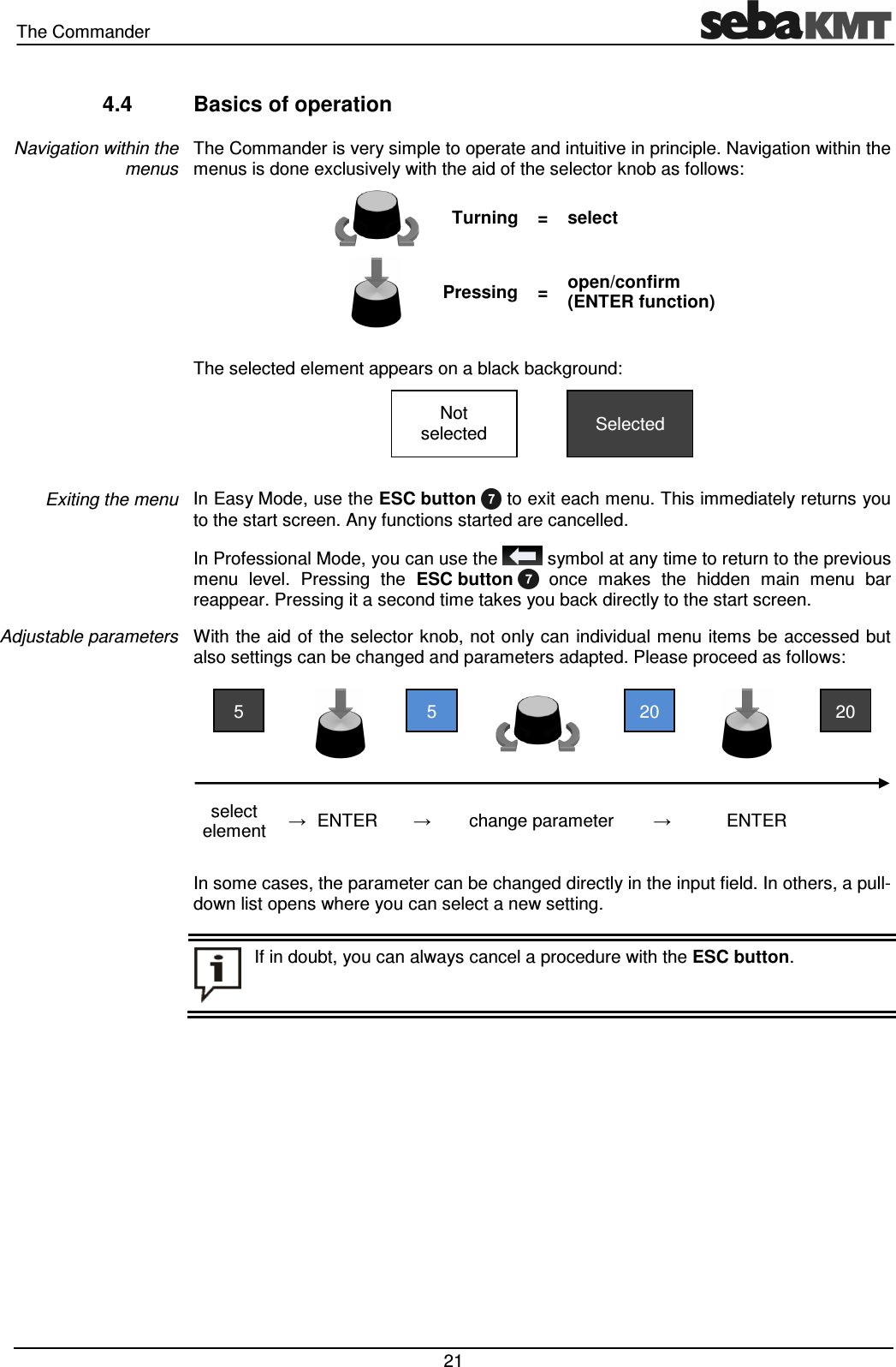
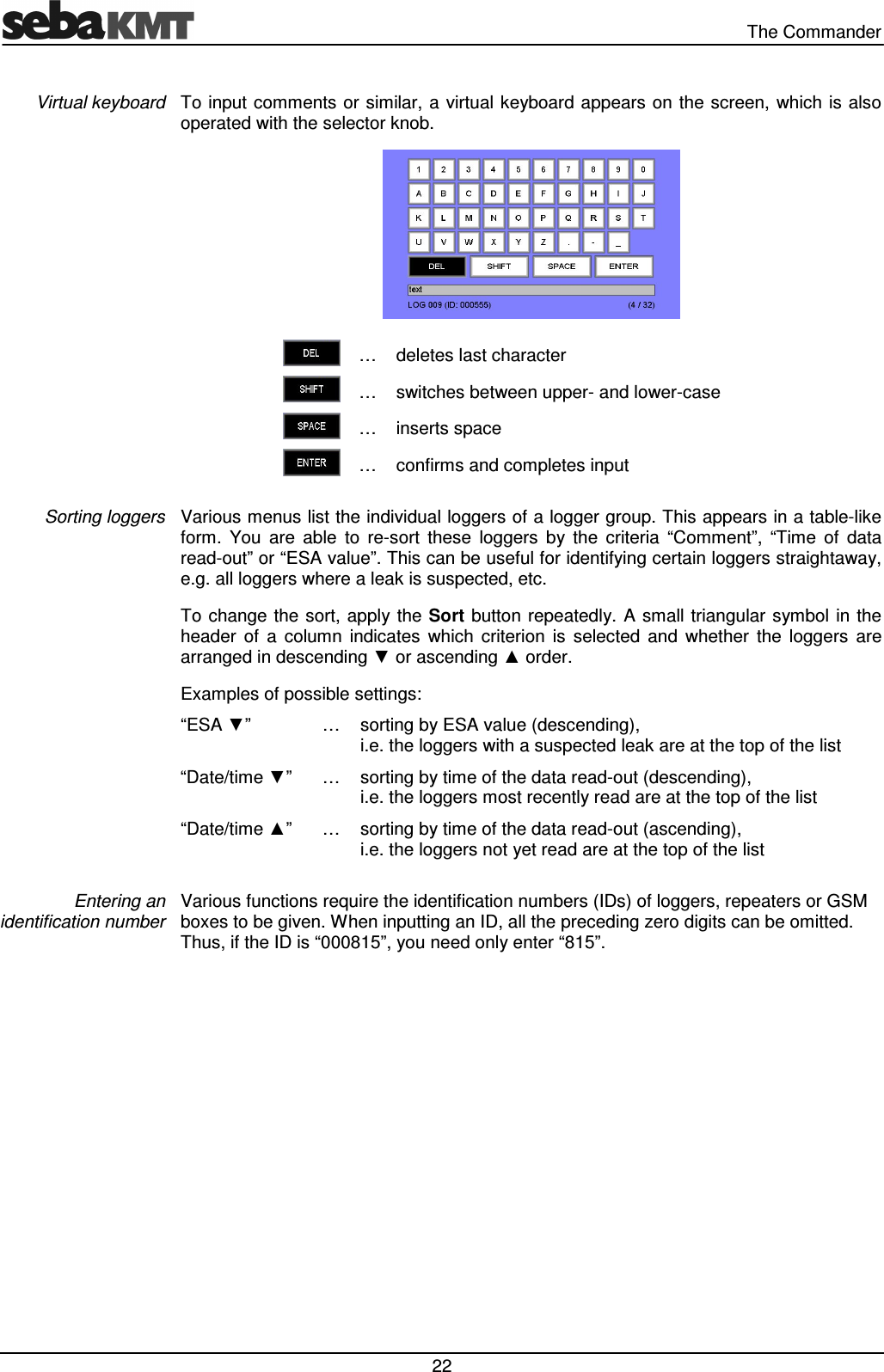
- 1. User Manual part 1
- 2. User Manual part 2
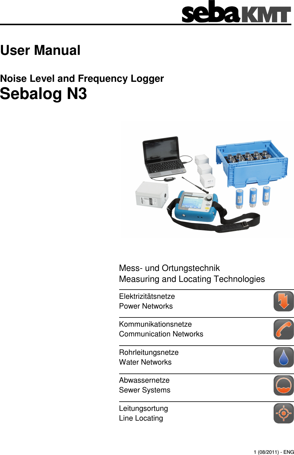
User Manual part 1