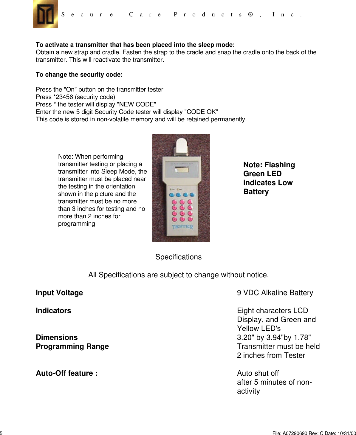
Secure Care TS0001 Security/ID System Alarm Transceiver User Manual Visio A07290690

Secure Care Products Inc Security/ID System Alarm Transceiver Visio A07290690

Exhibit D users manual per 2 1033 b 3

S    e    c    u    r     e          C    a    r    e        P    r    o    d    u    c    t    s    ®    ,       I    n    c    .Model 135 Tester(Part #A07290920)User GuideS    e    c    u    r     e          C    a    r    e        P    r    o    d    u    c    t    s    ®    ,       I    n    c    .3  9    C  h  e  n  e  l  l    D  r  i  v  e  ,C  o  n  c  o  r  d    N  H  ,    U  S  A    0  3  3  0  1  -  8  5  0  16  0  3  .  2  2  3  .  0  7  4  5  /  8  0  0  .  4  5  1  . 7  9  1  7Fax 6  0  3  .  2  2  7  .  0  2  0  0h  t  t  p  :  /  /  w  w  w  .  s  e  c  u  r  e  c  a  r  e  .  c  o  m1File: A07290690 Rev: C Date: 10/31/00
S    e    c    u    r     e          C    a    r    e        P    r    o    d    u    c    t    s    ®    ,       I    n    c    .Standard FeaturesTransmitter ID Code Tester-Default modeof OperationCut-band Zone TesterExit TesterTransmitter Sleep Mode ActivatorKeypad ProgammableAuto-Off featureProgrammable Security Code9 Volt Battery Powered2File: A07290690 Rev: C Date: 10/31/00
S    e    c    u    r     e          C    a    r    e        P    r    o    d    u    c    t    s    ®    ,       I    n    c    .INFORMATION TO USERFCC SECTION 15.21The user's manual or instruction manual for intentional or unintentionalradiator shall caution the user that changes or modifications not expresslyapproved by the party responsible for compliance could void the user'sauthority to operate the equipment.FCC ID: KNKTS0001This device complies with Part 15 of the FCC Rules. Operation is subject tothe following two conditions: (1) this device may not cause harmfulinterference and (2) this device must accept any interference received,including interference that may cause undesired operation.3File: A07290690 Rev: C Date: 10/31/00
S    e    c    u    r     e          C    a    r    e        P    r    o    d    u    c    t    s    ®    ,       I    n    c    . Testing InstructionsHow to Check a Transmitter ID Code: Press the "On" button on the Transmitter Tester. Bring the 13.56MhzTransmitter within 3" of the top of the Unit. (See picture on pg. 4 for proper orientation of the transmitter to thetester for best results ) The Yellow signal LED should begin flashing. The ID code of the Transmitter should bereceived by the unit and displayed on the LCD display. Verify that the ID code engraved on the transmittermatches the ID code displayed on the LCD display.  If the proper ID code has been received and displayed by theTester, then the transmitter is assumed to be operating properly. The tester will display "CHK XMTR" if anincorrect ID received or "_ _ _ _" if a transmitter ID was received incorrectly.How to test the Exit system: Press the "On" button on the Transmitter Tester. Press and hold the button marked"Door" on the tester. Approach the exit under test. When in range of the door receiver, red LED on the exit panelturns on, the door should lock if so equipped, and the the exit system should be armed. Move out of the detectionzone of the exit system. Push the door open and enter the detection zone of the exit system again. With the doorin the open position, the exit panel should enter an alarm state. The red and green LED's should be flashingalternately and an audible "seagull" alarm tone should be heard. Close the door and reset the exit panel.How to Test the Cut-Band Zone Receivers: Be sure to alert all Nursing and Security Staff prior to testing theCut-Band zone receivers. When the Cut-Band zone receiver is tested all exit systems will enter an armed state,locking all doors equipped with electromagnetic locks.Press the "On" button on the Transmitter Tester. Go to the Cut-Band zone under test and press the "Cut-band"button on the transmitter tester. Within a few seconds, all exit systems should enter the armed state, locking alldoors equipped with electromagnetic locks. The Nurse Station should enter an alarm state with audible alarm andalternately flashing red and Green LED's. The vacuum fluorescent display on the Nurse Station should indicatewhich cut-band zones have received the cut-band signal from the tester. Document which cut-band zones havereceived the cut-band test. Go to other areas of the protected unit and repeat the above test. Continue testing invarious areas until all cut-band zones have been tested and displayed on the Nurse Station.Important Note: The above tests are designed to simulate the actual operating characteristics of the system.Testing should be done on a weekly basis using a live transmitter to verify the actual operation of the ExitSystems and Cut-Band zones. Use the attached testing documents to document test results.Placing a Transmitter into the "sleep" mode: Prior to removing the cut-band transmitter from the monitoredresident or infant, the transmitter must be placed into the "Sleep" mode. If the transmitter is not placed into thesleep mode prior to cutting the transmitter strap, the system will detect the cutting of the strap and enter in the cut-band mode, arming all doors, lock all doors equipped with electromagnetic locks and creating an alarm conditionat the Nurse Station.Press the "On" button on the transmitter tester.Place the transmitter near the transmitter tester as shown in the picture.(see page 4)Enter *23456 (security code) on the keypad on the transmitter tester.Wait for the tester to display "Enable" within 2 secondsPress #10001 with the transmitter within 2 inchesTester will responds with either"SLEEP OK" or "SLP FAIL" after 10 seconds.With "Sleep OK" the band should be cut and the Transmitter will discontinue transmission. IF "SLP FAIL" appearsthe procedure should be repeated.In the event the transmitter is not placed into the sleep mode the Tester will display "SLP FAIL".If this occurs, verify the transmitter is being held near the tester as shown in the diagram and repeat the test.4File: A07290690 Rev: C Date: 10/31/00
S    e    c    u    r     e          C    a    r    e        P    r    o    d    u    c    t    s    ®    ,       I    n    c    .To activate a transmitter that has been placed into the sleep mode:Obtain a new strap and cradle. Fasten the strap to the cradle and snap the cradle onto the back of thetransmitter. This will reactivate the transmitter.To change the security code:Press the "On" button on the transmitter testerPress *23456 (security code)Press * the tester will display "NEW CODE"Enter the new 5 digit Security Code tester will display "CODE OK"This code is stored in non-volatile memory and will be retained permanently.Note: When performingtransmitter testing or placing atransmitter into Sleep Mode, thetransmitter must be placed nearthe testing in the orientationshown in the picture and thetransmitter must be no morethan 3 inches for testing and nomore than 2 inches forprogrammingSpecificationsAll Specifications are subject to change without notice.Input Voltage9 VDC Alkaline BatteryIndicatorsEight characters LCDDisplay, and Green andYellow LED'sDimensions3.20" by 3.94"by 1.78"Programming RangeTransmitter must be held2 inches from TesterAuto-Off feature :Auto shut offafter 5 minutes of non-activityNote: FlashingGreen LEDindicates LowBattery5File: A07290690 Rev: C Date: 10/31/00
Daily Transmitter Testing Log Date ______________________________Patient Name (last) First Name Transmitter ID# Transmitter TestPass \ Fail Transmitter ExpirationDate CommentsS    e    c    u    r     e          C    a    r    e        P    r    o    d    u    c    t    s    ®    ,       I    n    c    .Test All Transmitters in Use Daily. Test all Transmitters Prior to Placing Into Use.6File: A07290690 Rev: C Date: 10/31/00
Weekly 135 Exit System Test LogExit Location Doors lock Date Exit locationPass / Fail CommentsTest all the Exits on a weekly basisS    e    c    u    r     e          C    a    r    e        P    r    o    d    u    c    t    s    ®    ,       I    n    c    .7File: A07290690 Rev: C Date: 10/31/00
Monthly Cut Band Testing Log Date ______________________________Cut-Band Zone RCVD Signal Date Cut-Band TestPass \ Fail CommentsTest All Cut-Band Zones on a monthly basis.S    e    c    u    r     e          C    a    r    e        P    r    o    d    u    c    t    s    ®    ,       I    n    c    .8File: A07290690 Rev: C Date: 10/31/00
BY USING THIS PRODUCT, YOU ACKNOWLEDGE THAT YOU HAVE READ ALL OF THE TERMS ANDCONDITIONS OF THIS AGREEMENT, UNDERSTAND THEM, AND AGREE TO BE BOUND BY THEM.  YOUUNDERSTAND THAT, IF YOU PURCHASED THE PRODUCT FROM AN AUTHORIZED RESELLER OFSECURE CARE, THAT RESELLER IS NOT SECURE CARE’S AGENT AND IS NOT AUTHORIZED TO MAKEANY REPRESENTATIONS, CONDITIONS OR WARRANTIES, STATUTORY OR OTHERWISE, ON SECURECARE ’S BEHALF NOR TO VARY ANY OF THE TERMS OR CONDITIONS OF THIS AGREEMENT.If you do not agree to the terms of this Agreement, do not use this product and promptly return the product to the placeyou obtained it for a full refund.  If you should have any difficulty in obtaining such refund, please contact Secure Careat 1-800 451-7917.  YOUR USE OF THIS PRODUCT CONSTITUTES YOUR ACCEPTANCE OF THE TERMSAND CONDITIONS OF THIS AGREEMENT.I. NOTICEThis Secure Care Products, Inc., product must be used in accordance with this User Manual. Youunderstand that it is your responsibility that everybody who might be using the product knows the contentsof this User Manual and receives appropriate training. If you have any questions regarding the products andtheir use please call Secure Care Products, Inc. at the number provided in section II.3 below.II. LIMITED WARRANTY1. What This Warranty Covers:Subject to the limitations set forth below, Secure Care Products, Inc. warrants the conformity of itsproducts and accessories with the product specifications as set forth in this User Manual for each suchproduct, for the warranty periods stated in this User Manual.  Secure Care Products, Inc., at its option, willeither repair, replace or refund the purchase price of a non-conforming product during the warranty period,provided it is returned in accordance with the terms of this warranty.  Repair, at Secure Care Products,Inc.’s option, may include the replacement of parts, accessories or boards with functionally equivalentreconditioned or new parts, accessories or boards.  Replaced products, parts, accessories or boards arewarranted for the balance of the original warranty period.  Any replaced products and accessories, shallbecome the property of Secure Care Products, Inc. This express limited warranty is extended by SecureCare Products, Inc. to the original end-user purchaser and is not assignable or transferable to subsequentpurchasers.User Agreement/ Warranty StatementS    e    c    u    r     e          C    a    r    e        P    r    o    d    u    c    t    s    ®    ,       I    n    c    .9File: A07290690 Rev: C Date: 10/31/00
2. What This Warranty Does Not Cover:(a) Defects, damage or injury resulting from use of the product(s) in other than accordance with thisUser Manual and the product(s)’s labeling;  (b) Defects, damage or injury from misuse, accident, neglect orwhen the product(s) are used in conjunction with ancillary or peripheral sensing equipment notmanufactured or supplied by Secure Care Products, Inc.;  (c) Defects, damage or injury from improper orunauthorized testing, operation, maintenance, installation, adjustment, or any alteration or modification ofany kind;  (d) Products disassembled or repaired by anyone other than Secure Care Products, Inc. or itsauthorized representative and any defects, damage or injury caused by such products;  (e) Defects, damageor injury due to spills of or exposure to food, water or other liquid or other substance, except for normalnon-caustic cleaning agents used to clean the product;  (f) Defects, damage or injury resulting from cordsthat are stretched or have the modular tab broken;  (g) Defects, damage or injury as a result of the use of theproduct for longer or more often than specified in this User Manual; or (h) All externally exposed parts thatare scratched or damaged.3. How To Get Warranty Service:Warranty service is available by contacting Secure Care Products, Inc. service department at 800-451-7917and obtaining an Return Authorization Number.  The customer then ships the product to Secure CareProducts, Inc., authorized service center, shipping prepaid, along with a copy of the original invoice, ReturnAuthorization Number and description of the problem.4. No Other Warranty or RemedyThis is the complete warranty for the products by Secure Care Products, Inc.  Secure Care Products, Inc.assumes no obligation or liability for additions or modifications to this warranty unless made in writing andsigned by the President of Secure Care Products, Inc.  EXCEPT AS STATED ABOVE, SECURE CAREPRODUCTS, INC., DISCLAIMS ALL WARRANTIES, WHETHER EXPRESS OR IMPLIED, ORAL,OR WRITTEN, WITH RESPECT TO THE PRODUCTS, INCLUDING WITHOUT LIMITATION, ALLIMPLIED WARRANTIES OF MERCHANTABILITY, FITNESS FOR ANY PARTICULAR PURPOSEOR NON-INFRINGEMENT.10 File: A07290690 Rev: C Date: 10/31/00
11 File: A07290690 Rev: C Date: 10/31/00

Navigation menu