Secure Wireless EV-DW4955 Recessed Door/Window Sensor User Manual 7605 SW EV DW4955 Manual
Secure Wireless, Inc Recessed Door/Window Sensor 7605 SW EV DW4955 Manual
UserManual.wiki
>
Secure Wireless
>
EV DW4955 User Manual
User Manual
Navigation menu
Upload a User Manual
Namespaces
Wiki Guide
HTML
PDF
Info
Views
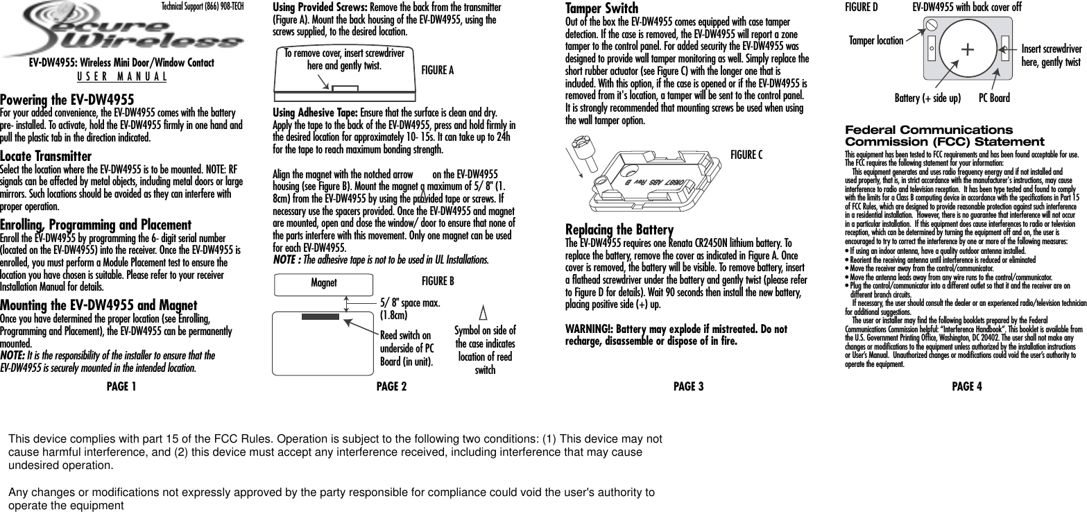
User Manual
Discussion / Help
Navigation