Securitron EPT EPTL 500 14250_G EPT, Installation Instructions I 14250 G
User Manual: Securitron EPT, EPTL Installation Instructions Installation Instructions
Open the PDF directly: View PDF ![]() .
.
Page Count: 4
Securitron Magnalock Corp. www.securitron.com ASSA ABLOY, the global leader
Tel 800.624.5625 techsupport@securitron.com
in door opening solutions
© Copyright, 2011, all rights reserved PN# 500-14250
Page 1 Rev. G, 04/11
EPT / EPTL ELECTRICAL POWER TRANSFER
INSTALLATION INSTRUCTIONS
Includes: EL-EPT / EL-EPTL – ElectroLynx Version
1. DESCRIPTION
The EPT/EPTL allows an electric lock or exit device, such as a Securitron Touch Sense Bar or
Touch Sense Handle device, to be installed while concealing the cabling on the hinge side of the
door between the edge of a door and door frame. The EPT/EPTL includes a flexible steel shield
approximately 5/16” [7,9mm] (I.D.) inside diameter.
The EPT/EPTL power transfer devices are able to be installed onto doors accompanied with Full
Mortise Butt Hinges, Continuous Butt Hinges or Offset Pivot Type Hinges. The Pivot Type Hinge
styles may have up to a 3/4” [19,0mm] offset maximum.
Note: The EPT/EPTL models are not compatible with doors
containing Swing Clear Type Hinges or Center Pivot Type Doors.
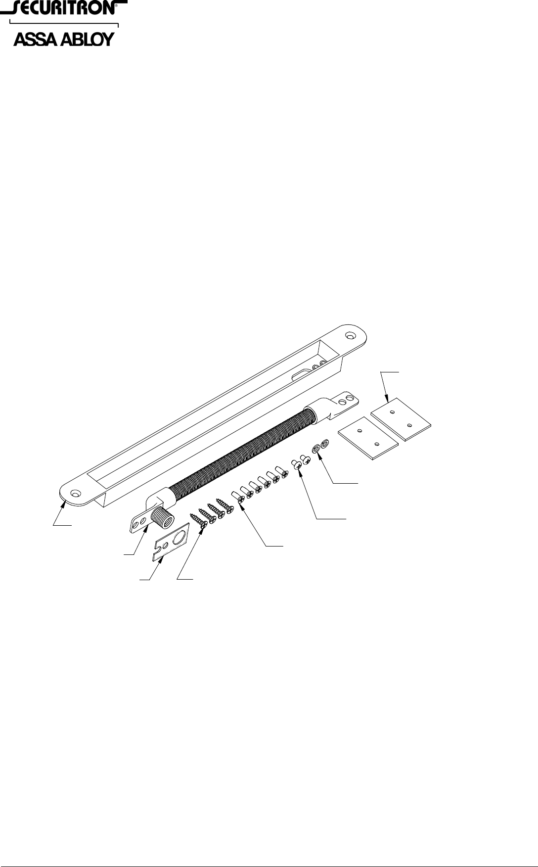
2. PRODUCT OVERVIEW
Upon unpacking this product, an inventory should be made to insure that all of the required
components have been included. Along with these Instructions and the Installation Template,
this product should include the following items:
(4)
#6 - 5/8" SMS Screw
(6)
6-32 x 3/8" Type "F"
Self Tapping Screw
(2)
8-32 x 3/16" PPH Screw
(2)
#8 Split Helical Washer
(1)
Flexible Shield
(1)
Lead Cover
(2)
Flush Tab Bracket
(1)
Bezel Plate
3. PHYSICAL INSTALLATION
It is recommended to edge mount the EPT/EPTL in the upper half of a steel door and the lower
half of a wood door. The EPT/EPTL Lead Cover should be a minimum of 6” [152,4mm] from the
middle butt hinge cutout or centered between the butt hinges. Prior to installation, ensure that
you have the correct version of the EPT/EPTL for the door/frame. The EPT is used for door swing
gap distances of 2-1/2” [63,5mm] or less between door edge and the door frame. The EPTL is
used for longer door swing gap distances greater than 2-1/2” [63,5mm].
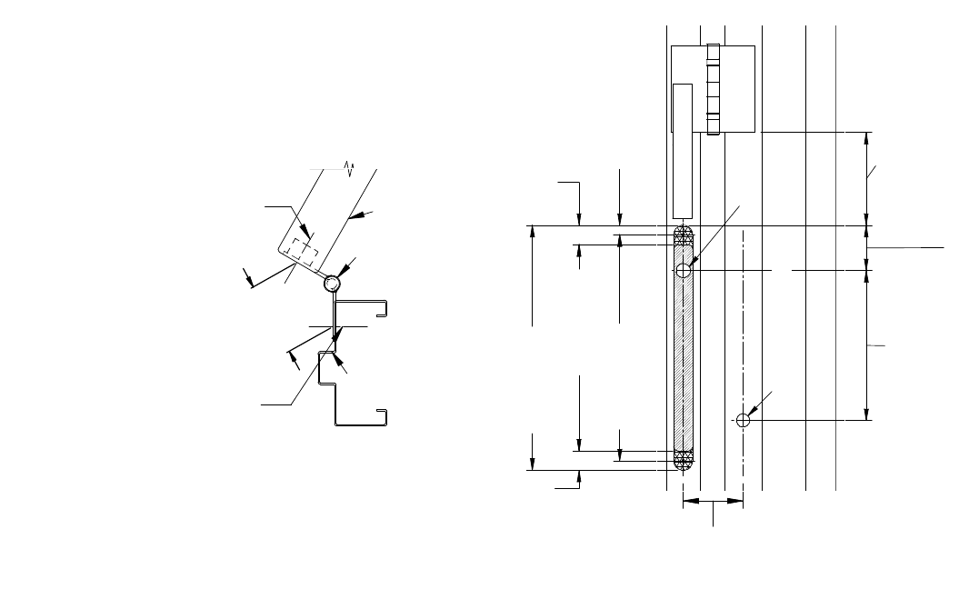
A simple measurement may be taken to determine the correct EPT/EPTL for the application. To
measure the swing gap distance, open the door its full travel distance. Measure the distance
from the centerline of the door edge to the centerline position on the door frame as shown in
Figure 1. If this distance is 2.5” [63,5mm] or less an EPT may be used. If the distance is greater
than 2.5” [63,5mm] an EPTL must be used. Once the correct unit is determined, use the
following step by step procedure to correctly install the EPT/EPTL.
Note: The door stile, number of hinges and distance between hinges
may vary depending upon the door manufacturers. Consult the specific
door manufacturer to help decide if the EPT/EPTL will fit the application.
PN# 500-14250
Page 2 Rev. G, 04/11
SWING GAP DISTANCE
MEASUREMENT:
EPT ~ LESS THAN 2.5" [63.5mm]
EPTL ~ GREATER THAN 2.5" [63.5mm]
(DOOR)
(HINGE)
(DOOR FRAME)
CENTERLINE REFERENCE
3/4" [19,0mm] DIAMETER
HOLE IN DOOR EDGE AND
SLOT FOR MOUNTING LEAD COVER
CENTERLINE REFERENCE
11/16" [17,5mm] DIAMETER
HOLE IN DOOR FRAME FOR
MOUNTING FLEXIBLE CABLE
7.80EPT: [198,1]
EPTL: 16.30 [414,0]
3/4" [19,0] Diameter
11/16" [17,5] Diameter
6.00 [152,4] or
Recommended (Minimum)
Center Between Butt Hinges
These Two (2) Centerlines
Must Align When Door Is Closed
.495
[12,7]
1.01
[25,7]
10.75 [273,1]
19.40 [492,8]
1.01
[25,7]
12.77 [324,4]
21.43 [544,3]
11.77 [299,0]
20.43 [518,9]
2.45 [62,2]
Centerline of Door
Centerline of Door
Figure 1 Figure 2
Wood Doors and Frames
Using a router, cut the main recess slot into the edge of the door .700” [17,8mm] deep as
explained in Figure 2 and Figure 3. Reset the router depth to .075” [1,9mm] and route the two
(2) recess flange areas for the flush mount tabs. Place the lead cover into position and mark the
location of the cable exit oblong hole and the mounting hole locations. Remove the Lead Cover
and drill the (2) two holes using a 1/8” [3,2mm] diameter drill approximately 1/2” [12,7mm]
deep. Drill the 3/4” [19,0mm] diameter hole into the door edge. Pass cable from the exit device
through the hole in the door edge. Pass the cable through the oblong hole in the Lead Cover.
Properly attach the two (2) electrical connectors at the door location. Mount the Lead Cover into
place using the two (2) #6 x 5/8” Flathead Type-A Screws provided. Locate and mark the
mounting holes for the Flexible Shield onto the door frame. Drill the 11/16” [17,5mm] diameter
hole into the door frame. Drill (2) two holes using a 1/8” [3,2mm] diameter drill approximately
1/2” [12,7mm] deep for mounting of the Flexible Shield. Pass the cable through the Flexible
Shield and apply Bezel Plate if not preassembled. Properly attach the two (2) electrical
connectors at the frame location and pass into the hole of the door frame. Mount the Flexible
Shield onto the Lead Cover using the two (2) 8-32 x 3/16” Screws and #8 Split Helical Washers
provided. Align the cable and the other end of the Flexible Shield onto the door frame and
secure using the two (2) remaining #6 x 5/8” Flathead Type-A screws provided as shown in
Figure 4.
Note: The frame side of the Flexible Shield requires the Bezel Plate
for concealing the oversize hole when mounted to the frame.
Metal Doors and Frames:
Metal doors must also have a flush surface mount installation. The door/frame manufacturer
may prepare a pre-fabricated tab for internal mounting capabilities or use the Flush Tab Brackets
provided. The cut out for the Lead Cover may be cut with a radius or square cornered as noted in
Figure 3 and on the Template provided. If field retrofit installation is being performed, route the
complete perimeter of the bracket and tab area and install the EPT/EPTL using the Flush Tab
Brackets provided. When mounting the Lead Cover, drill the mounting holes 1/8” [3,2mm] and
use the 6-32 x 3/8” Type “F” Self Tapping Screws provided. Follow the Template provided for
placement of the screw holes for the Flush Tab Brackets. Also when mounting the Flexible Shield
to the metal door frame, drill the same holes at 1/8” [3,2mm] and use the two (2) remaining 6-
32 x 3/8” Type “F” Self Tapping Screws.
Note: Applications containing combinations of doors or frames made of wood
or metal; follow the proper procedures related to the device as necessary.

PN# 500-14250
Page 3 Rev. G, 04/11
The illustration of Figure 3 represents the configurations for both the solid core wood door and
metal door installations. This is to help to understand the process for flush mounting the
EPT/EPTL in the correct manner for the door application required.
(6)
6-32 x 3/8" Type "F"
Self Tapping Screw
(2)
Flush Tab Bracket
(4)
#6 x 5/8" SMS Screw
(1)
Lead Cover
(1)
Lead Cover
Metal Door
Installation
Wood Door
Installation
.700 [17.8]
R0.50 [12,7] x
.075 [1,9]
Deep Recess
Flange Area
Square Corner
or
Radius Corner
Countersink for
#6 Flathead Screw
Figure 3
Note: Routing is generally performed into the edge of the door (as shown)
but this can be reversed with the routing being done into the frame.
EPT/EPTL Special UL / Electrical Note:
• To maintain this product’s compliance with UL listings (UL 10C and UBC 7-2-1997), the
maximum number of electrical conductors to be used is twelve (12) - using No. 20-22 AWG size
wire.
• Electrical rating for the EPT and EPTL is 1Amp @ 12V or 24V – AC or DC.
- - - - - - - - - - - - - - - - - - - - - - - - - - - - - - - - - - - - - - - - - - - - - - - - - - - - - - - - - - - -
EL-EPT / EL-EPTL
ElectroLynx VERSION
1. DESCRIPTION
ElectroLynx is a standardized plug-in connection system which allows for the easy installation of
door mounted hardware. Door mounted locking hardware, doors, hinges or power transfer
devices and frames are available pre-wired from ASSA Abloy companies with universal plug-in
connectors for a simplified, time saving field installation.
2. OVERVIEW
The structural design of the ElectroLynx version is the same as the EPT/EPTL unit. It includes an
additional 12 conductor cable placed in the Flexible Coil with 2 connectors applied on each end
containing an 8 pin and a 4 pin connector pre-wired pin-to-pin.
3. PHYSICAL INSTALLATION
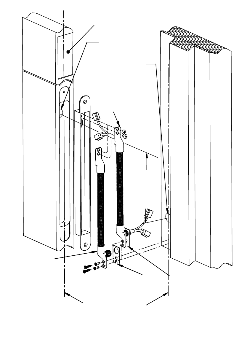
The installation of the ElectroLynx Version (EL) is similar to the standard EPT/EPTL. The
ElectroLynx Version comes pre-harnessed on both ends with dual harness plug adapters for
system accessories as illustrated in Figure 4. The dual harness connectors provided come out of
the back side of the Lead Cover for connection to the door edge accessory devices. The opposite
end also contains dual harness plug adapters to connect into device signal lines through the door
frame accessory devices.
PN# 500-14250
Page 4 Rev. G, 04/11
Attach all proper connections of the harness at the door location. Push the cable and connectors
back into the hole of the door. Mount the Flexible Shield to the Lead Cover as shown in Figure 4.
Mount the Lead Cover as described in Figure 3 and Figure 4. Attach the proper connections at
the frame location. Push the cable and connectors back into the frame. Mount the Flexible Shield
to the frame as described in Section 3 and the EL-EPT/ EL-EPTL Physical Installation in Figure 4.
Note: The frame side of the Flexible Shield also contains a Bezel Plate over the
extended spring section for concealing the oversize hole once mounted to the frame.
11/16" [17,5mm]
Diameter
C
L
3/4" [19,0mm]
Diameter
THESE TWO
CENTERLINES
MUST ALIGN
WHEN THE DOOR
IS CLOSED!
Center Butt Hinge
Cutout Area of Door
Pre-Assembled
Bezel Plate
(Installation Hardware)
Flexible Shield
(ElectroLynx)
EL-EPT
EL-EPTL
Flexible Shield
EPT
EPTL Bezel Plate
(Installation Hardware)
C
L
C
LC
L
7.80 [198,1] /
16.30 [414,0]
Dimensions in [Brackets] are metric (millimeter)
Figure 4
EL-EPT/EL-EPTL ElectroLynx Electrical Note:
Electrical Rating: EL-EPT and EL-EPTL is 1 Amp @ 12V or 24V – AC or DC
