Securitron TSB 3 SERIES 500 16400_C Installation And Operation Instructions IO 16400 20C
User Manual: Securitron TSB-3 Installation and Operation Instructions Installation Instructions
Open the PDF directly: View PDF ![]() .
.
Page Count: 11

Securitron Magnalock Corp. Tel 775.355.5625
550 Vista Boulevard Fax 775.355.5633
Sparks, NV 89434 info@securitron.com
www.securitron.com
© Copyright, 2010, all rights reserved PN# 500-16400
Page 1 Rev. C, 08/10
ASSA ABLOY, the global leader
in door opening solutions
SECURITRON SERIES TSB-3 TOUCH SENSE BAR
INSTALLATION AND OPERATION INSTRUCTIONS
1. DESCRIPTION
Securitron's Model TSB-3 is an exit device for doors secured by magnetic locks. The assembly consists of
an aluminum bar available in lengths to fit on standard U.S. door openings: (36", 42", and 48"),
PolyCarbonate end pieces to mount the bar on the door, and an electronic touch sensor mounted within
the bar. Fasteners for metal doors are included. For through door mounting please call factory for a no-
charge TSB-TDM kit. Note that US type or metric fasteners are supplied depending of the version of
the bar which has been ordered. The metric version part numbers include the suffix: “M”. When the bar
is touched, a relay in the sensor is tripped, releasing the lock. The bar's sensitivity is adjustable. In the
unlikely event of sensor failure, a push switch is mounted on the back side of the bar. Depressing the
switch has the same effect as activating the sensor by touch and therefore represents built in safety
redundancy. The TSB cannot be used outside in rain conditions.
As the TSB-3 is normally used to allow egress on an electrically secured door, make sure that
you are complying with applicable building codes for your area. Check with your local building
department and/or fire prevention department.
2. PHYSICAL INSTALLATION
2.1 MOUNTING HOLE MARKING
The first step is to plan and mark the mounting hole positions. Be sure that you have the correct length
bar for the door and begin by removing the screws that secure the end caps on both ends of the bar. If it
appears that the bar is longer than it should be for the door, see Section 2.6 for cutting instructions.
Note which end has the sensor (circuit board) in it. This is the end that should be mounted on the
hinge side for easiest wire exit from the door.
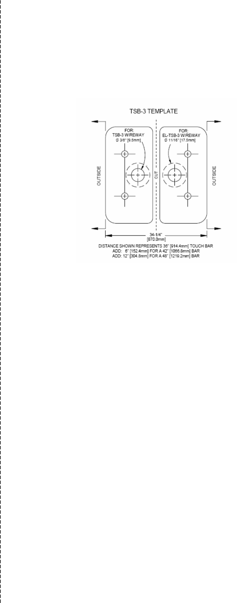
For mounting hole drilling, we supply a template located at the end of this instruction manual, although it
is generally preferable to hold the bar in position and use it as a "self-template." The templates are
particularly valuable if door preparation is to be done in advance. In setting your mounting holes, there
are three concerns:
They must be level or the bar will be tilted.
They must be the correct distance apart.
They must be correctly placed "left/right" on the door.
Leveling is best done by use of a carpenter's level. If one is not available, measure from the mounting
hole positions on each edge of the door to the door bottom. This is not as effective as it assumes that the
door is level which is not always true. Note that in general, US building codes require the height of the
bar above the door bottom to be between 30 and 44 inches.
If the bar is used as its own template, you will automatically get correct separation between the mounting
holes. If you use the templates, note that there is a line drawn on each template which must line up with
the outer edge of the plastic end pieces on the bar. After you've mounted the templates, hold up the bar
to make sure the end piece lines up to get the correct distance.
Left/right placement on the door is an important point. In most installations, the bar should be centered
on the door. This produces the most attractive result. However, if the door has a vertical door stop on
the edge that swings open, you may need to shift the bar somewhat towards the hinge side to avoid
scraping the stop when the door opens. You should always experimentally position the bar on the
door and open the door to see that there is no interference. Finally, if the installation is on an
aluminum frame glass door, make sure you don't position the bar so that the mounting screws go into the
glass. On standard doors, keeping the mounting holes at least 3/4" (19 mm) from the inner edge of the
aluminum will be safe.
2.2 MOUNTING HOLE DRILLING
There are three different procedures depending on the door type. Hollow metal doors employ supplied
machine screws and "blind nut" fasteners. This method leaves the outside of the door unaffected. Longer
machine screws and sex bolts may be used on hollow or solid wood doors, solid metal doors, or chalk filled
fire doors, the TSB-TDM kit for this type of mounting can be ordered from the factory at no-charge. With
this method, the sex bolt heads do show from the outside of the door. Note that the Touch Sense Bar
may not be used on a fire rated door that requires a fire rated latch (the TSB-3 has no latch), but
sometimes fire doors are used on openings where a fire rated barrier is not required, because the
customer has selected this door type for other reasons (such as solidity). The third method is to use wood
PN# 500-16400
Page 2 Rev. C, 08/10
screws (not supplied) on a solid wood door. By "solid wood", we mean hardwood interior rather than
pressed wood as the wood needs enough structural integrity to hold wood screws. This method is strong
and simple and has the advantage of not showing sex bolts heads from the outside of the door.
For a hollow metal door, drill four 3/8" (9.5 mm) diameter holes only deep enough to get through the
inner side of the door- not completely through the door.
For through bolt mounting on various door types, drill four 1/4" (6 mm) holes completely through the
door. For this type of installation (which may also be elected for a solid wood door) you will be using
screws and finishing sex bolts suitable for a 1 3/4" (44 mm) thick door supplied in the TSB-TDM kit.
Nearly all North American commercial doors are this thickness. If the doors you are working on are
different, you will have to purchase different length screws or apply some spacing techniques (described
later).
For a solid wood door, you may elect to mount the bar with wood screws (not furnished). We
recommend 2 3/4" (70 mm) #14 wood screws with a hex, pan, oval or round head. Drill four 3/16" (5
mm) diameter holes to a depth of 1 1/4" (30 mm).
2.3 WIREWAY HOLE DRILLING
The TSB-3 connects to its power source and to the devices it controls via a six-conductor cable with push-
on connector (supplied). There are several different methods of getting this cable from the TSB-3 to
external connection points. The first issue is whether the cable needs to enter the door (in which
case a wireway hole must be drilled in the door), or not. For most installations, it is preferred that the
cable enter the door. Exit from the door may be via the supplied door cord which may be mounted at the
top of the door where it is out of the way, or via any of many commercially available transfer hinges or
pivots (such as Securitron’s model EPT Electric Power Transfer or ELH Electric Hinge) which serve to route
the wiring off the door in a concealed manner. A wireway hole is then drilled into the door in the position
shown on the template. It should be 3/8" (9.5 mm) in diameter. The cable is then pulled into the door.
An alternate technique exists which does not route the cable into the door but which takes it directly
from the end piece to the frame via the door cord. This technique is preferred when the door type is
difficult to pull a wire through (such as any solid door). It is also a good technique when the frame is not
hollow as the door cord can route the cable directly from the end piece to a surface box mounted opposite
the end piece.
For the best security and appearance, you will not use the plastic door cord terminator when you route the
cord into the end piece. You will drill a hole in the plastic end piece. The hole should be drilled through
the bottom flat of the end piece on the hinge side. The ideal hole size is 23/64" (9.1 mm) but as this drill
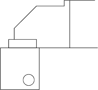
size is unusual, 3/8" (9.5 mm) also works. On the next page, a drawing appears to the right which shows
you hole location in the end piece. Note that this drawing shows the end piece you would select if the
hinge side of the door was on the left. If it's on the right, use the other end piece but still locate the hole
at the inner, rear corner. With this method, the door cord is used to route the cable directly from the end
piece to the frame.
2.4 WIRE ROUTING
If you elect the method of wire routing which uses a hole in the end piece (see drawing above), you must
route your cable through the end piece prior to mounting the end piece to the door. This is
because the flat cable connector will not pass through the hole you have drilled in the end piece. Begin by
threading the cable end without the connector down through the elongated slot in the end piece (the
slot is directly under the circuit board). From there, route it through the drilled hole in
the end piece. Begin by threading the cable end without the
connector down through the elongated slot in the end piece (the slot
is directly under the circuit board). From there, route it through the
drilled hole in the end piece so that it exits the end piece. Next pass
the stainless door cord over the cable and slide it until you can push it
into the hole you have drilled in the end piece. Secure the stainless
cord inside the end piece with the supplied "E" clamp. See Figure 1.
It shows this assembly for the end piece you would use for a door with
hinges to the left. If the hinges are on the right, use the opposite end
piece. The drawing will be "reversed" but the concept is unchanged.
Note that if you are mounting to a surface box, a second "E" clamp has
been supplied so that you can simply drill a hole in the box and secure
the stainless cord from the inside with the second "E" clamp. If the
frame is hollow, you would employ the plastic door cord terminator
when you mount the other end of the door cord to the frame. You are
now ready to mount the bar to the door.
BOTTON VIEW OF
HINGE SIDE END
PIECE. DRILL 23/6
OR 3/8" HOLE AS
SHOWN, ABOUT
3/16" IN FROM
EACH EDGE.
PN# 500-16400
Page 3 Rev. C, 08/10
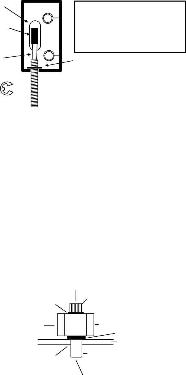
FIG. 1: REAR VIEW OF END PIECE SHOWING CABLE ROUTING THROUGH END PIECE
"E" CLAMP STAINLESS DOOR CORD INSERTS
INTO HOLE DRILLED IN BOTTOM
OF END PIECE. SECURES WITH
"E" CLAMP
"E" CLAMP INSTALLED TO
SECURE STAINLESS CORD
6 CONDUCTOR
JACKETED CABLE
CABLE CONNECTOR
WHICH ATTACHES
TO CIRCUIT BOARD
ELONGATED SLOT RECOMMENDED TOOLS
MEDIUM, SMALL PHILLIPS DRIVERS
DRILL MOTOR
1/4", 3/8, 1/8" DRILL BITS
WIRE CUTTER/STRIPPER
VOLT/OHM METER
CRIMP CONNECTORS AND PLIERS
If you are using the preferred method of pulling the cable through the door, the cable must be inserted
into the 3/8" wireway hole you have drilled in the door. The connector will be left protruding from this
hole. The connector will pass through the elongated slot in the end piece, so the cable should be pulled
first and then the bar may be mounted. If you are using the door cord rather than a transfer hinge or
pivot to bring the cable from the door into the frame, remember that you must pass the cable through the
cord before fishing it into the frame.
Note that if, for any special reason, you find it desirable to pull the cable through the bar, this must not
be done. The cable must always exit the bar at the end piece which includes the circuit board.
If it goes through the bar, it creates electronic interference with the touch sensing function which voids
the performance of the bar.
2.5 BAR MOUNTING
The holes you have drilled for bar mounting (Section 2.2) were different depending on the type of door.
Similarly the final mounting procedure depends on the door type.
In the case of a hollow metal door, identify the four supplied blind nuts. The nuts are used as follows.
Insert the nuts with the knurl engaging the edge of each hole. Then utilize the supplied collapsing tool to
collapse the nuts. Use of the tool is shown in Figure 2. Next, use the shorter (2 1/4" or 54 mm)) supplied
machine screws. Place a tooth washer under the head of each screw and mount the bar. Do not over
torque. FIG. 2: COLLAPSING THE BLIND NUTS (METAL DOOR)
DOOR
TOOL
CAP SCREW
BLIND NUT
DRILL 3/8" (9.5MM) HOLE
NUT AS SHOWN
PRESS IN BLIND COLLAPSES WHEN CAP SCREW
TURNED WITH ALLEN WRENCH
WHILE TOOL HELD FAST
WITH BOX WRENCH
WHILE TURNING WITH ALLEN
WRENCH, PRESS IN TO KEEP
NUT SEATED IN DOOR
HOLD WITH WRENCH OR
CAP SCREW
VISE GRIP WHILE TURNING
FLAT WASHER
KNURL
For through bolt + sex bolt mounting, you will be using a longer 3 1/2" (90 mm) machine screws with
the sex bolts supplied in the TSB-TDM kit. You should have already drilled 1/4" (6 mm) holes through the
door. The next step is to install the sex bolts. From the outside of the door, enlarge the holes to 3/8"
(9.5 mm) diameter, 1" (25 mm) deep. Push in the sex bolts. Then place a tooth washer under the head
of each screw and mount the bar. Note that the screw length is suitable for a 1 3/4" (44 mm) thick door.
Nearly all North American commercial doors are this thickness. If you have a door of different thickness,
a number of techniques can be applied. Screws of different lengths can be purchased or the supplied
screws may be cut (if the door is thinner). Since the sex bolts are short, however, some final adjustments
may be necessary. Spacing washers may be added under the screw heads but if you raise the heads too
high they will interfere with removal of the circuit board (if this ever becomes necessary). The board can
still be removed but the mounting screws will have to come out first and this is inconvenient. Another
PN# 500-16400
Page 4 Rev. C, 08/10
technique that is possible on solid doors is to recess the sex bolts into the door by using a 1/2" (12.5 mm)
counter bore.
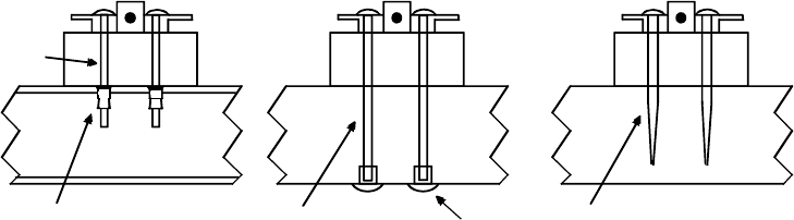
In the case of a solid wood door, if you have elected to use wood screws (not furnished), place a tooth
washer under the head of each screw and mount the bar. Figure 3 provides a visual reference for these
three methods.
2.6 CUTTING THE BAR
If the bar needs to be shortened to install properly, it can be easily cut in the field. It must be cut from
the end which does not mount the sensor. Remove the end piece completely by unscrewing the two
self tapping screws that hold it to the bar. It is better to remove both end pieces so as to avoid damaging
the sensor circuit board by metal filings. Note that when you remove the second end piece which carries
the sensor, the sensor will slide out easily with the end piece. There is, however, a ring terminal which
circles one of the end piece-to-bar mounting screws. This ring terminal is connected by a wire to the
circuit board. This connection is how the sensor "sees" the bar. When you reinstall the end piece, be sure
to reinstall the ring terminal.
FIG. 3: END VIEW SHOWING USE OF DIFFERENT FASTENING METHODS
THREE MOUNTING METHODS DEPENDING ON DOOR TYPE
METAL DOOR
SOLID WOOD DOOR
WITH WOOD SCREWS
SELECTED
THROUGH BOLT
+ SEX BOLT MOUNTING
BLIND NUT
2 1/4" (57MM)
MACHINE
SCREW
2 3/4" (70MM)
WOOD SCREW
3 1/2" (90MM)
MACHINE
SCREW
SEX
BOLT
NOTE: ALWAYS PUT TOOTH
WASHER UNDER SCREW HEAD
Cutting is ideally performed by a band or cut-off saw to produce a neat result. However, with care, a
hacksaw can be used. The cut need not be perfect because the bar "pockets" into the end cap. This hides
a poor cut from viewing from the front. The rear of the bar is not pocketed, however, and if the bar is
being mounted on an aluminum frame glass door, a sloppy cut will be apparent from the outside and will
worsen the appearance of the installation.
3. ELECTRICAL CONNECTIONS
3.1 SENSOR WIRING
The TSB-3 has 6 colored wires which are for sensor power and DPST relay output:
Red - "+" DC Power
Black - "-" DC Power
White - Relay Common, Pole 1
Green - Relay Normally Closed, Pole 1
Blue - Relay Common, Pole 2
Orange - Relay Normally Open, Pole 2
The cable connector is plugged into the male connector on the circuit board so that the cable routes
directly back into the end piece. The relay has 2 amp contacts and when the bar is touched, the relay
changes state. For additional safety, the operation of the TSB is fail safe, itself. When the TSB
receives power, its control relay automatically energizes. It deenergizes when the unit is touched. For
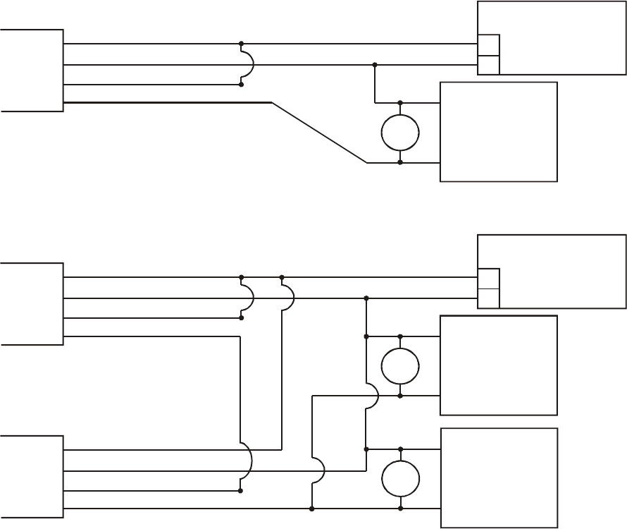
releasing a magnetic lock, the following drawing (Figure 4) shows typical connections of sensor, power
supply and fail safe (released when powered) lock. Fail secure electric locks are normally not permitted
for use with the TSB on required exit applications. NO contacts, however, are available from the sensor
for special signaling applications and for integration with the Request to Exit (REX) function of an access
control installation, as will be explained. Note installation of the MOV in parallel with the electric lock. The
MOV is supplied loose with the TSB. It is a black or blue disk-like component with two bare wires for
connection. The MOV acts to suppress the lock’s inductive kickback which will greatly shorten the life of
the relay contacts if not suppressed. To work properly it should be spliced in as close to the electric lock
PN# 500-16400
Page 5 Rev. C, 08/10
as possible. It has no polarity. If, however, Securitron's Magnalock is used in the installation, the
MOV is not necessary as the Magnalock is internally suppressed.
FIG. 4: TSB WIRING FOR MAGNETIC LOCK
+
_
POWER SUPPLY
12-24 VOLTS
CABLE
RED (+ POWER)
BLACK (- POWER)
WHITE (RELAY COM1)
GREEN (RELAY N.C.1)
MOV MAGNETIC
LOCK
+
_
CABLE
RED (+ POWER)
BLACK (- POWER)
WHITE (RELAY COM1)
GREEN (RELAY N.C.1) MOV MAGNETIC
LOCK
+
_
+
_
POWER SUPPLY
12-24 VOLTS
CABLE
RED (+ POWER)
BLACK (- POWER)
WHITE (RELAY COM1)
GREEN (RELAY N.C.1)
MOV MAGNETIC
LOCK
+
_
TSB WIRING FOR ONE MAGNETIC LOCK
T
SB WIRING FOR MULTIPLE MAGNETIC LOCKS
NOTE 1: MOV NOT NEEDED IF SECURITRON MAGNALOCK USED
NOTE 2: POWER SUPPLY MUST ALWAYS CONNECT DIRECTLY TO SENSOR
NOTE 3: IN POWER HOOK UP, POLARITY MUST BE OBSERVED
The sensor operates on 12-24 volts DC and is normally powered by the same power supply that operates
the lock. When connecting power, polarity must be observed. Note that the sensor draws 40 mA
when "at rest" and 25 mA when it is releasing the lock. As an additional safety feature, the TSB
includes a low voltage sensing circuit. The unit will keep working normally if input voltage declines
until it reaches roughly 9 volts. At that point, the TSB will automatically act as if all power was removed.
If a lock is being controlled, it will release. Input voltage could decline if the unit was being operated on
batteries and the batteries were discharging or because of a fault in the power supply.
3.2 DOUBLE BREAK WIRING
Many installations include a controlled access device such as a digital keypad or card reader. Such devices
typically have a REX (request to exit) input. When dry contacts close on this input, the entry device will
open the lock for the same amount of time that is programmed for entry. Use of the REX input for exit
has two benefits: you pick up timed exiting and also in the case of most entry controls, the REX input
must be used for exiting to avoid an alarm condition at the door.
If the REX input alone is used for exiting a safety/reliability problem will exist. If the entry
device malfunctions, exit will not be possible and people may be trapped. We therefore always
recommend double break wiring which is supported by the TSB-3 because of its two pole relay. The
TSB's NC contacts are used to break power to the fail safe electric lock while its NO contacts trip the REX
input of the controlled entry device. This releases the lock a second time, hence the term, "double break".
If the controlled entry device fails for any reason, direct exit is still possible.
3.3 ALL SECURITRON EQUIPMENT INSTALLATION
Figures 4 and 5 show "generic" use of the Touch Bar with any type magnetic lock and power supply.
Often, Securitron supplies all of these products and the installer expects an interconnection drawing for all
Securitron products. We provide such drawings in many of our manuals. In this case, the replacement of
PN# 500-16400
Page 6 Rev. C, 08/10
the generic products shown above with Securitron products is so simple as not to require separate
drawings. Just note that for any Securitron Magnalock, the red wire denotes the "+" input and the black
wire denotes the negative. Remember that you don't need to install the MOV with any Securitron
Magnalock. Securitron offers a wide range of different power supplies, so it is necessary to consult the
individual power supply manual to identify the DC output terminals. Then connect the power supply
outputs to the rest of the system as shown above.
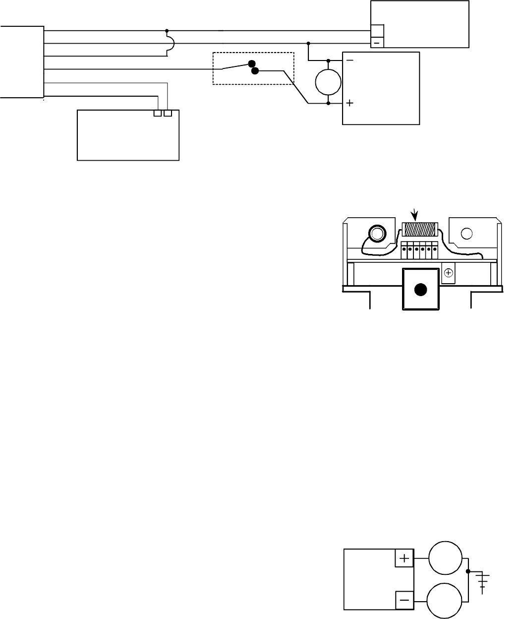
FIG. 5: TSB DOUBLE BREAK WIRING
CABLE
RED (+ POWER)
BLACK (- POWER)
WHITE (RELAY COM1)
GREEN (RELAY N.C.1)
POWER SUPPLY
12-24 VOLTS
+
MOV
ACCESS CONTROL
REX INPUT
ACCESS CONTROL
LOCK CONTROL
NC CONTACTS
BLUE (RELAY COM2)
ORANGE (RELAY N.O.2) MAGNETIC
LOCK
NC NC
3.4 CAUTION ON USE WITH PROXIMITY CARD READERS
When a proximity card reader is used for entry and a Touch Bar is used
for egress, there is a small possibility of interference. The proximity
reader projects an electric field of considerable intensity and we have
seen rare cases where this can be picked up by the TSB. It depends
on the power of the proximity reader and the nearness of the reader
on the outside of the door to the bar on the inside. To make sure a
problem does not exist after the installation is complete, perform the
following test. Turn the bar sensitivity up as high as you can to the
point just before it is open all the time (see Section 3.6). Then, from
the outside of the door, place your hand on the reader and lean your
body against the door to see if the bar can be triggered. Coupling the
reader's energy though your body into the door, tends to increase the
bar’s sensitivity
If you find that the bar triggers from this test, there is some
interference. You have two options. It may be that the interference is
so little that when the sensor is adjusted down, there is no risk of
triggering from the outside. Experiment with this. Alternately,
Securitron has developed a simple filter circuit which will absorb the interference from the reader. See the
drawing above. This requires a 22,000 Micro Henry inductor (DigiKey part # M7223-ND, JD Miller part #
70F222AI). To install the inductor, identify the ring terminal which connects the left screw going into the
bar to the circuit board pad marked "bar". Clip this wire at the board and connect it to the left lead from
the inductor. Solder the right lead of the inductor into the pad marked "bar" on the sensor’s right side.
This pad is currently unused. Lay the inductor on top of the connector to finish.
3.5 CAUTION WITH SWITCHING POWER SUPPLIES
The TSB-3 is capable of being operated by a wide variety of power supplies and does not require regulated
power but a certain type of power supply called "switching" can interfere with operation.
Most regulated power supplies are of the "linear" type. Some switching
supplies can produce line noise which will affect the TSB and rendering it
hard to adjust. If you find that a TSB is hard to adjust, check the power
supply. If it is a switcher, the power supply can be replaced with a
linear Securitron unit or addition of two capacitors generally solves the
problem. Connect one .01 mF capacitor between power supply + and
earth ground. Connect a second .01 mF capacitor between power supply
negative and earth ground. See the drawing to the left.
3.6 ADJUSTING SENSITIVITY
With wiring completed, sensor adjustment should be set. Note that the sensor board has a potentiometer
on it accessible when the bar's end cap is removed (see Figure 6). The potentiometer on the sensor will
increase sensitivity when turned clockwise and decrease it when turned counterclockwise. Turn the pot
clockwise without touching the bar with a small flat blade screwdriver until you hear the relay click off.
In this condition, sensitivity is so high that the bar is “sensing” all of the time. Slowly rotate the pot
counter-clockwise until you hear the relay click off and then another 15 degrees counter-clockwise. This is
SWITCHING
POWER
SUPPLY
.01 mF
.01 mF
EARTH GROUND
INDUCTOR
SOLDER ONE END OF INDUCTOR
INTOPADMARKED"BAR"ONRIGH
T
SIDE OF SENSOR. CLIP WIRE
FROM RING TERMINAL, REMOVING
IT FROM SENSOR AND CONNECT
IT TO OTHER END OF INDUCTOR.

PN# 500-16400
Page 7 Rev. C, 08/10
generally a good setting. Before replacing the end cap, experiment by touching the bar and observe that
the lock releases. Experiment with gloves if you expect that they will be used. You may want to increase
the sensitivity somewhat, but if you leave it just below the point where it is continuously released, you
risk a condition where the unit will fail by being released all the time.
FIG. 6: END VIEW OF SENSOR/CIRCUIT BOARD
CABLE CONNECTOR (MALE)
RING TERMINAL
MAKES
CONTACT
FROM
SENSOR
TO BAR
POTENTIOMETER
BACKUP PUSH BUTTON
(ON OPPOSITE SIDE)
CIRCUIT BOARD
3.7 USE OF REDUNDANT (BACKUP) SWITCH AND LABELS
A red push switch is mounted on the rear of the bar. The purpose of this switch is to provide backup in
case of any malfunction or misadjustment of the sensor. Pushing the button breaks the connection
between the white (COM1) and green (NC1) wires just the same way as if the bar was touched. It
therefore provides a "hard" backup circuit break which will release the controlled fail safe lock. It does not
however affect the COM2 and NO2 circuit (blue and orange). If these NO contacts are being used, for
example, to provide REX input to an access control system, pushing the backup button will not achieve
this, but egress safety is maintained as with the switch mounted, there are two independent controls
which can release the door. In the event that the sensor fails, the button will still work.
A label is supplied which should be affixed to the bar (see drawing to
the right) to draw attention to the backup switch. Application of the label
is particularly important where people encounter the bar who are not
familiar with it such as in a public occupancy. The label includes two
arrows owing to the uncertainty of which end of the bar it will be
mounted on.
A second label stating “PUSH TO EXIT” is also shipped with the bar. If
desired, this label cab be affixed to the front center of the bar itself in
order to prompt users that the bar (rather than the door) must be pushed
to gain egress.
4. ELECTRIC LOCK SELECTION
Electric lock selection is important to obtain best results from the TSB. The product allows silent and
immediate egress without the mechanical action of traditional exit devices which require periodic
maintenance and replacement. Having no moving parts, the TSB possesses an extended operating life.
The product was designed for use with Securitron's Magnalock. The Magnalock secures the door
with magnetic force only and therefore has no possibility of jamming and thereby denying egress. The
Magnalock also has internal electronics which allow it to release very rapidly. When used with the TSB,
which is also a fast device, exit is immediate and the impression a person exiting gets is that the door is
not locked at all. Other magnetic locks generally operate significantly more slowly than the Magnalock.
This makes egress less convenient as a person must pause somewhat after touching the bar until the door
releases.
5. OPERATIONAL SECURITY CONSIDERATIONS
Typical use of the Touch Sense Bar provides free egress from the interior protected area. The electric lock
secures against unauthorized entry. It is of important concern that persons on the outside cannot activate
the bar from the outside. This is a common problem with other interior release devices. For instance, if a
panic bar with switch is used, it is possible to trip it from the outside if the intruder can introduce a coat
hanger in between the door and frame. Aluminum frame glass doors tend to allow this more than other
types. Similarly, microwave detectors used on the inside can sometimes be activated from the outside if
the door is vibrated strongly.
The Touch Sense Bar is more secure with respect to the outside. To assure this, however, the user must
be made aware of certain operational characteristics. The sensor functions by setting up an oscillating
electric field which conforms along any metal surface that contacts the sensor's antenna wire. In the
Touch Sense Bar it is the bar itself that carries the field. The electric field is disturbed by the near
EMERGENCY
RELEASE
BUTTON
PN# 500-16400
Page 8 Rev. C, 08/10
proximity of ionized fluids within the body, which form a conductive mass. It is this mass that the bar
detects. As a proximity device the bar is sensitive to the closeness of the mass. For example, if a person
wearing gloves touches the bar with his finger tip, the door will generally not release. When the gloved
hand is wrapped around the bar in normal use, the door will release because the conductive mass of the
hand is in much closer contact with the bar.
The main security concern regarding outside entry is if a person could introduce a metal wire from the
outside and make metal to metal contact with the bar. The field could then propagate along the wire and
be activated by the intruder's hand. In practice, this is unlikely. The bar is anodized and therefore
insulated so it will not make contact with the wire. The intruder would have to scratch away the
anodization which requires both effort and knowledge. Also the field propagates weakly along a thin wire.
If, however, high security from the outside is critical in the application, two steps should be taken. First,
the sensitivity of the bar should be set as low as satisfies the exit performance requirements. Second, the
insulation on the bar should be increased by painting it. This significantly increases resistance to
scratching. Electrostatic (powder coat) paint is recommended for greatest toughness.
6. SENSOR REPLACEMENT
A: Remove the end cap on the sensor side. Remove the cable connector from the circuit board.
B. Remove the two screws that connect the end piece to the aluminum bar. Note that this will free the
ring terminal that is soldered into the board on the pad marked, "bar". This ring terminal is the way the
sensor makes contact with the bar. Slide the complete end piece out of the bar.
C: With the end piece now loose in your hand, push the circuit board farther into the end piece. The
direction is as if you were pushing it into the bar. There will be some resistance from the wires that
connect the backup switch to the circuit board. Push it only far enough to completely reveal the
rectangular body of the backup switch.
D: Unscrew the plastic retaining ring that holds the backup switch to the end piece. Push up the freed
backup switch. Now the complete sensor + backup switch can be slid away from the end piece by
continuing to slide the board in the same direction.
E: To install the new sensor assembly, reverse the procedure detailed above. But note that the wires that
connect the backup push button to the circuit board must be folded over in the center of the board- inside
of the potentiometer. If the wires are allowed to fold outside the potentiometer, they will block access to
it and the board will not be able to slide fully forward.
PN# 500-16400
Page 9 Rev. C, 08/10
APPENDIX A
TROUBLESHOOTING
PROBLEM- The door will not release when the bar is touched.
To monitor operation of the bar, it is quite easy to hear the relay click when the bar is touched. If you
don't hear a click, try the backup switch. If the door does not release from the backup switch, it is
almost certain that the overall wiring of the installation is at fault. If the door releases from the backup
switch, the general wiring is correct but the sensor is not reading your touch. Make sure you understand
section 3.2 on how to adjust sensitivity of the bar. It may be set too low. Another fault could be that the
sensor itself is not receiving 12-24 DC power on the red and black wires. Check the power supply and, be
sure the input polarity is correct. Also, even if power is being applied on the red and black wires, it's
possible that it's not getting into the sensor. Check the connector block that plugs into the sensor card for
loose wires. Finally, it is possible that the ring terminal that connects the sensor to the bar itself has
come loose. See Figure 6.
If you can hear this click and the door does not release, try the backup switch. If the door still doesn't
release, the problem must be in the installation wiring as it is nearly impossible to have a failed sensor
relay and backup switch at the same time. Review your wiring to make sure the sensor is correctly
applied in the circuit. If you hear the click but only the backup switch releases the door, call the factory
as the defect appears to be in the relay contacts and the sensor will have to be replaced.
PROBLEM- The door remains released constantly
If you hear a click when you touch the bar but the lock remains released, the problem is probably in the
wiring which should be reviewed to be sure the sensor is correctly applied in the circuit. If you don't
hear a click, the sensor is probably adjusted too high (review section 3.2). Rotate the adjustment pot
counter-clockwise while not touching the bar. If this doesn't lock the door, some effect is probably
keeping the relay deenergized all the time (remember; the relay is energized when the lock is secure to
maintain fail safe operation).
The most likely cause for the relay to remain energized is that the sensor "sees" an overwhelmingly large
signal as if someone was continually touching the bar. This will happen if the bar is not properly isolated
from a metal door. Because of the plastic end pieces, the intrinsic isolation of the bar from the door is
many times greater than it needs to be. Make sure that there is no "foreign object" creating a conductive
path from the bar to the door. An example would be metal blinds.
The same effect will occur if the bar is used outside in the rain or if water is flowing down the inside of the
door. This overcomes the electrical isolation needed between the bar and door.
Certain large electronic noise sources can "swamp" the sensor although this is rare. Examples would
include large radio or radar transmitters in the building or a high voltage neon sign mounted within a few
feet of the door. Call the factory if you suspect noise induced problems.
Finally, in very rare instances, the sensor can “hang up” in a condition that continuously releases the door.
De-power the unit and turn the adjustment pot all the way counterclockwise. Then, re-power the unit and
note that the door locks. Then, readjust the sensor potentiometer normally.
IF YOUR PROBLEM PERSISTS, CALL SECURITRON: 1-800-MAG-LOCK
PN# 500-16400
Page 10 Rev. C, 08/10
MAGNACARE LIMITED LIFETIME WARRANTY
Warranty information visit: www.securitron.com/en/site/securitron/About/MagnaCare-Warranty
PN# 500-16400
Page 11 Rev. C, 08/10
TSB-3 TEMPLATE
Do not photocopy
CUT ALONG DOTTED LINES
