Securitron XMS 500 18000_D Installation And Operating Instructions IO 18000 20D
User Manual: Securitron XMS Installation and Operating Instructions Installation Instructions
Open the PDF directly: View PDF ![]() .
.
Page Count: 8
Securitron Magnalock Corp. www.securitron.com ASSA ABLOY, the global leader
Tel 800.624.5625 techsupport@securitron.com
in door opening solutions
© Copyright, 2011, all rights reserved PN# 500-18000
Page 1 Rev. D, 10/11
SECURITRON MODEL XMS EXIT MOTION SENSOR
INSTALLATION AND OPERATING INSTRUCTIONS
1. DESCRIPTION
The XMS is a passive infrared motion detector specifically designed to release a magnetic lock
from the inside for free egress. Unlike burglar alarm type detectors, the XMSìhas special
features appropriate to this use. The lock control function is fail safe so that the magnetic
lock will safely release if power is cut to the detector. A relay is also present to send a REX
(request to exit) signal to an access control system (if one is present) and therefore shunt an
alarm report. A time extension feature avoids the problem of the unit resetting if a person
momentarily stops moving just before exit. Tight control of the exit detection pattern allows
maximum security from the outside and avoidance of inadvertent activation from the inside.
Since egress from a magnetically locked door can be a safety issue, make sure you are
complying with local building codes. Contact your building and/or fire prevention
department.
2. PHYSICAL INSTALLATION
2.1 PLACEMENT OF THE UNIT
The XMS is intended for indoor use only. It is positioned with respect to the inside of the door
so that its detection pattern will “see” a person approaching the door while maintaining good
security from the outside. There are different options as to where the unit is placed depending
on variables in the application.
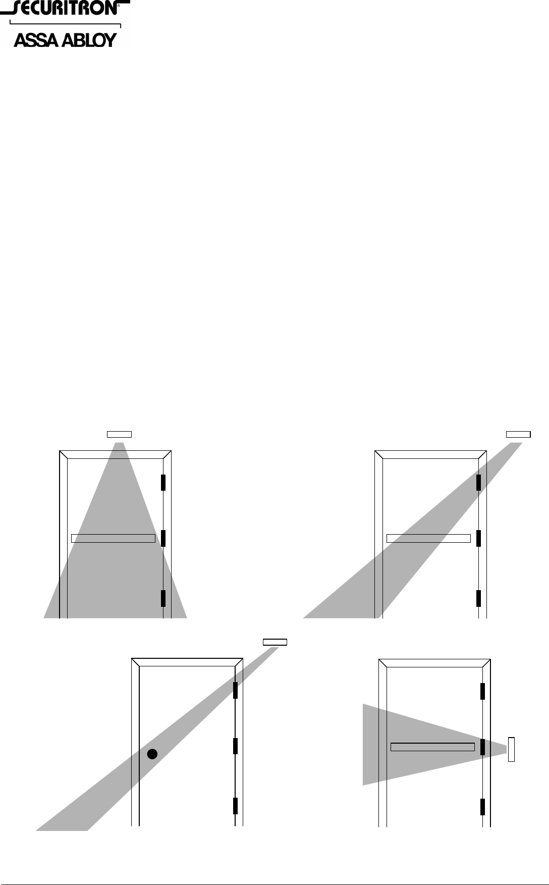
FIG. 1: PLACEMENT OPTIONS FOR THE SENSOR
FOR TRAFFIC CONTROL
APPLICATIONS, MOUNT THE
SENSOR IN THE CENTER OF
THE DOOR WITH THE
PATTERN AS SHOWN
FOR SECURITY
APPLICATIONS, THE
PATTERN SHOULD SWEEP
ACROSS THE EXIT DEVICE
BUT MISS THE BOTTOM OF
THE DOOR. THE SENSOR IS
POSITIONED BEYOND THE
HINGE SIDE OF THE DOOR
WHEN A DOORKNOB IS
PRESENT IN A SECURITY
APPLICATION, THE
PATTERN CAN BE MADE
MORE NARROW
THE SENSOR CAN BE
POSITIONED AT THE
SIDE FOR SECURITY
APPLICATIONS ON
DOORS AT THE END
OF CORRIDORS
The simplest method of placing the unit is for traffic control applications. A traffic control
application is one where you do not expect any attempt at breaking in from the outside. The
PN# 500-18000
Page 2 Rev. D, 10/11
unit is simply centrally positioned above the door with the pattern covering the door (setting the
pattern is addressed later in this manual).
For security applications, you will set your position to defend against someone activating the
detector from the outside. This can be done by inserting a heated object under the door. To
deal with this threat, the unit is positioned above and outside of the door hinges with the pattern
adjusted so that it sweeps across the door but does not detect the bottom of the door. If the
door includes an exit bar, the pattern must be broad as a person’s approach to the door is
variable. If it includes a door knob or lever handle, the pattern can be adjusted more
narrowly.. A final option for security applications is to position the unit at the side of the door
so that it sees across the door. This can be used for doors at the end of corridors. You would
not want to employ this approach for non corridor doors as the door would be released by
someone walking near it (maximum detection range is 20-25 ft.) Side of door mounting has the
disadvantage of greater exposure to vandalism but defends against objects being inserted under
the door and provides excellent coverage along the full width of the door. Note that for the end-
of-corridor application, the unit can be positioned on the same wall plane as the door or on a
wall which is next to the door and perpendicular to it. You have the choice because the pattern
can be adjusted a full 90 degrees with respect to the sensor’s mounting plane.
2.2 FIXING THE UNIT TO THE WALL
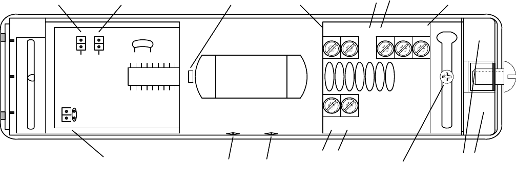
First, locate the screw on the end of the unit and loosen it. This permits you to remove the
cover. The appearance of the interior is shown in Figure 2. Note that the interior electronics is
mounted on a rotating barrel which is locked by the “Barrel Locking Screw” shown in Figure 2.
Loosen this screw and rotate the barrel fully upward so that you can remove it. This leaves you
with the back piece and you will see two slotted holes for physical mounting and a choice of two
wire entry points (also shown on Figure 2). Most installers prefer to pull the cable through the
wall first and then mount the unit. If you’re not sure of your wire count for the cable, consult
the next section at this time but completion of physical installation consists only of screwing the
back piece to the wall and pulling the cable through one of the wire entries. Then you will
replace the barrel assembly and attach the wires to the screw terminals.
FIG. 2: XMS OVERVIEW
IC
AB
LED FAST
IN+ DEVICE C1 NC1 NO1
BARREL LOCKING
SCREW
+-
12-28 VDC
POWER
LOCK CONTROL REX RELAY
WIRE
ENTRY
HOLES
AIMING
SCREWS
SENSITIVITY
JUMPER
LED LOGIC
JUMPER
TIME SET
JUMPER
BI-COLOR
LED
3. WIRING
3.1 INPUT POWER
To power the unit, filtered and regulated DC voltage between 12 and 28 volts should be applied
to the power input terminals (see Figure 2). This connection should be permanently made to
the power supply rather than switched through some other device. The XMS should receive
constant power. Make sure you observe correct polarity with this connection. If you reverse
the input power polarity, the unit will not be damaged but will appear to be dead. Power
consumption for the XMS is approximately 20 mA.
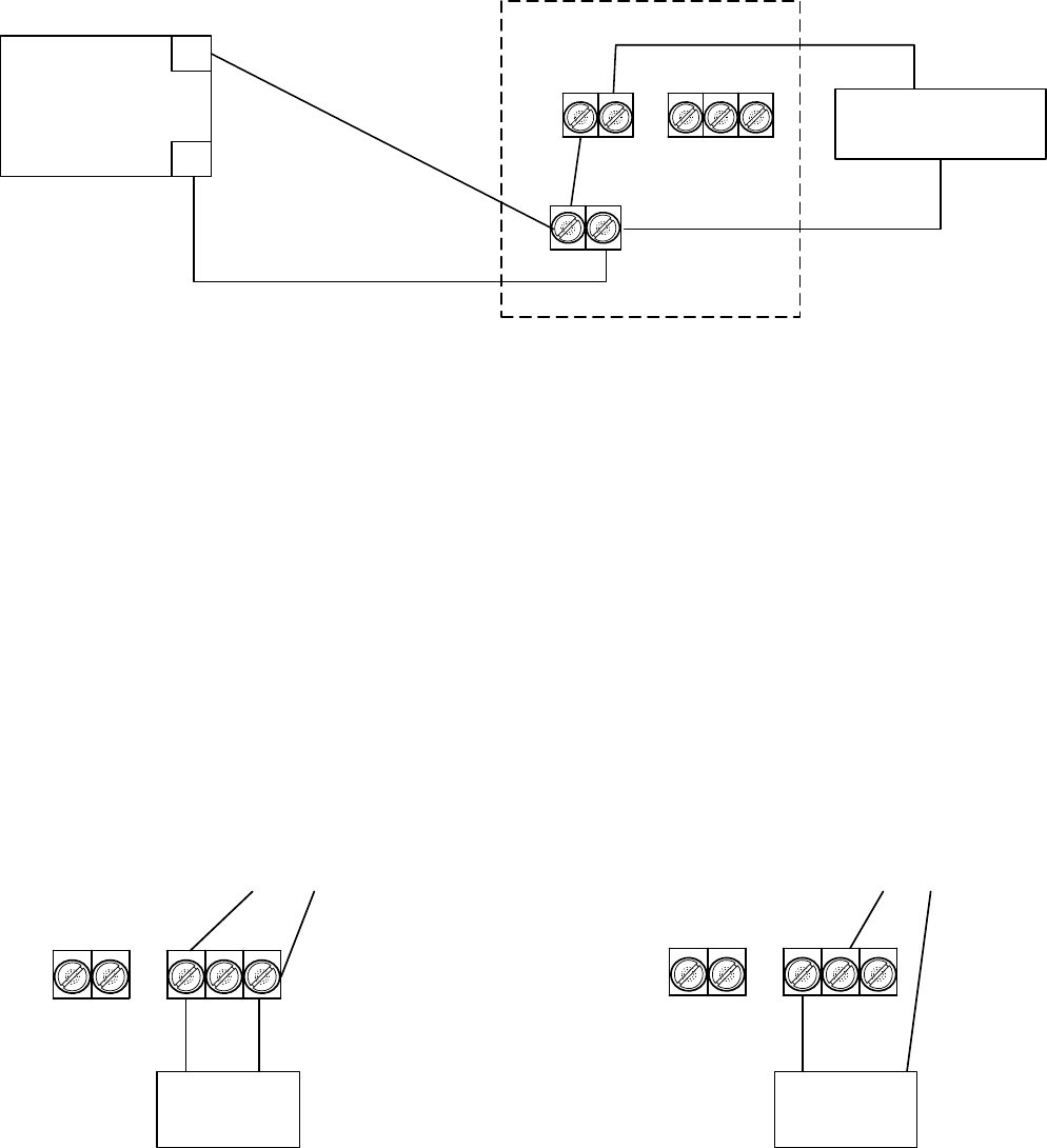
3.2 WIRING WITH MAGNETIC LOCK ONLY
This is the simplest application which releases the magnetic lock from the inside for free egress
but is not concerned with shunting any alarm point at the door. It is shown in Figure 3.
INPUT
PN# 500-18000
Page 3 Rev. D, 10/11
FIG. 3: WIRING WITH MAGNETIC LOCK ONLY
12-28 VDC
POWER
SUPPLY
+
-
MAGNETIC LOCK
+
-
+
-
XMS
MATCH POWER
SUPPLY VOLTAGE TO
MAGNETIC LOCK
VOLTAGE
IN+ D VICE C1 NC1 NO1
Note that how positive power to the lock connects through the terminal block “IN+” and
“DEVICE”. These two terminals constitute an internal field effect transistor which does the
actual switching. If power to the XMS was somehow interrupted, the field effect transistor would
automatically open (releasing power to the lock). This makes the XMS “fail safe”. Note:
never use the REX relay contacts to switch the magnetic lock. These contacts only have
enough capacity for signaling; they cannot reliably switch magnetic lock current.
If you need to integrate a controlled entry unit such as a digital keypad, use a set of NC
contacts from the entry unit to break the wire between “DEVICE” and magnetic lock “+” to allow
the entry unit to release the lock.
3.3 SHUNTING AN ALARM POINT
This technique is for installations where the door is connected to an alarm system and that if
the door opens without the XMS having been activated, an alarm signal should result. When the
XMS is employed to open the door, the alarm signal should be shunted.
FIG 4: WIRING TO SHUNT ALARM SYSTEM ON DOOR
DOOR
SWITCH
TO ALARM PANEL
DOOR
SWITCH
TO ALARM PANEL
ALARM SIGNAL WHICH IS
CLOSED WHEN DOOR IS CLOSED:
OPENS TO ALARM
ALARM SIGNAL WHICH IS
OPEN WHEN DOOR IS CLOSED:
CLOSES TO ALARM
IN+ DEVICE C1 NC1 NO1 IN+ DEVICE C1 NC1 NO1
The alarm system will be connected to a door switch or other detector at the door via two wires.
You will need to determine if this “loop” is closed when the door is closed and opens when the
door opens or is open when the door is closed and closes when the door opens. Correct wiring
to shunt the alarm is shown in Figure 4 for either instance. You utilize the “REX” relay contacts
for this shunting while the lock control relay contacts continue to release the magnetic lock.
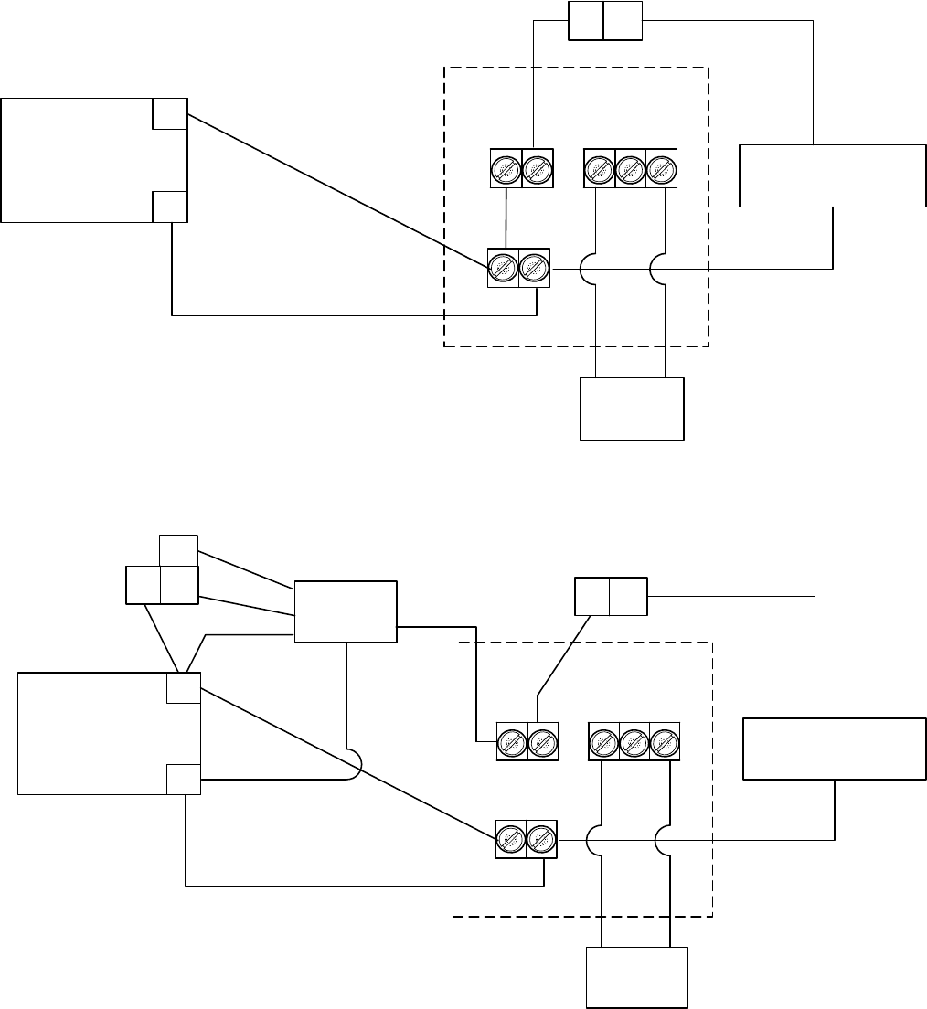
3.4 INTEGRATION WITH ACCESS CONTROL SYSTEM
An access control system permits entry (generally from a card reader) and will also often act as
an alarm system if a door is forced. To integrate with the XMS and a magnetic lock, the access
system should have a two-terminal REX (request to exit) input. When this input is closed, the
access system will operate its lock control relay to release the lock and will not create an alarm
signal as it will consider the exit event a “legal” one. Wiring is shown in Figure 5. Note that with
this wiring method, the lock control terminals of the XMS directly break power to the magnetic
lock as do the access system contacts. This is called “double break” wiring. It enhances safety
PN# 500-18000
Page 4 Rev. D, 10/11
and reliability as if the access system experiences a fault, the XMS still allows safe egress. If the
access system is not monitoring the door, connection to the REX input is not required. In that
case, make all other connections as shown in Figure 5 except the REX input.
FIG. 5: WIRING WITH AN ACCESS CONTROL SYSTEM
12-28 VDC
POWER
SUPPLY
+
-
MAGNETIC LOCK
+
-
+
-
XMS
REX
INPUT
CNC
ACCESS SYSTEM LOCK CONTROL RELAY
USE 1/2 SECOND TIME
SETTING WITH ACTIVE REX
(SEE SECTION 5)
IN+D VICE C1 NC1 NO1
FIG. 6: WIRING WITH “GENERIC” PUSH BUTTON AND TIMER
12-28 VDC
POWER
SUPPLY
+
-
MAGNETIC LOCK
+
-
+
-
XMS
REX
INPUT
CNC
ACCESS SYSTEM LOCK
CONTROL RELAY
TM-8L
TIMEMATE
CNC
YEL
RED GRN
WHT
BLK
PUSH BUTTON
NO
USE 1/2 SECOND TIME
SETTING WITH ACTIVE REX
(SEE SECTION 5)
IN+ D VICE C1 NC1 NO1
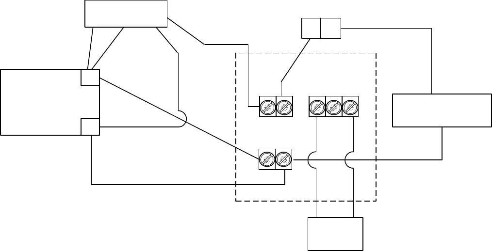
3.5 “ACCESS CONTROLLED EGRESS DOOR”
In some jurisdictions, the combination of a magnetic lock, access control system and exit
detector such as the XMS can be considered an “access controlled egress door”. The applicable
section of the Life Safety Code calls for a redundant means of exit in the event of a problem with
the detector. This is typically a push button located 40-48” above the floor and within five ft. of
the door. Pushing the button will directly release power to the magnetic lock and the lock shall
remain released for 30 seconds. This can be accomplished with any of Securitron’s push buttons
and the model TM-8L timer. Figure 6 shows proper wiring.
Securitron also manufactures a line of push buttons with integrated timers (EEB2 and
EEB3N). These are easier to use with the XMS to satisfy the code requirements for access
controlled egress doors. Figure 7 shows wiring with the integrated push button/timers.
PN# 500-18000
Page 5 Rev. D, 10/11
FIG. 7: WIRING WITH INTEGRATED PUSH BUTTON AND TIMER (EEB2, EEB3N)
12-28 VDC
POWER
SUPPLY
+
-
MAGNETIC LOCK
+
-
+
-
XMS
REX
INPUT
CNC
ACCESS SYSTEM LOCK
CONTROL RELAY
RED
GRN
BLK
USE 1/2 SECOND TIME
SETTING WITH ACTIVE REX
(SEE SECTION 5)
IN+D VICE C1 NC1 NO1
EEB2, EEB3N
PUSH BUTTON
WHT
4. BASIC OPERATION
When the XMS is first powered, its LED will flash twice quickly every second for about 40
seconds. This is a self test and also permits the XMS to adjust itself to the thermal
environment that it “sees”. After this start up period, the LED will stay green. If the self test
fails during the start up period, the LED will begin to flash at four times per second. This failure
indication will continue indefinitely. If you see it, de-power the unit for about 30 seconds and
then re-power it. If the failure indication occurs again, replace the unit. During the self test
period the unit’s control outputs are in their “normal” conditions (lock control-conducting; REX-
relay deenergized).
In the event of a very brief power outage, the unit will not self test for 40 seconds but will
undergo a self test of 10 seconds before resuming normal operation. Note that the self test on
power up feature of the unit is the main reason why the XMS must receive constant power.
With the jumpers in factory set condition and the unit past its self test, it will detect moving
objects at a different temperature than ambient. It will signal this detection by switching its LED
from green to red. The LED actually mirrors the state of the REX relay rather than the lock
control transistor.
You need to understand how the unit’s control outputs operate in a detection event. In the rest
condition (green LED on; no detection), the lock control transistor is conducting and the
REX relay is deenergized. When an object is detected, the REX relay energizes immediately.
This is to shunt alarm contacts or send a REX signal to an access control system. Fifty
milliseconds later, the lock control transistor switches off which releases the magnetic lock.
This brief delay is to make sure that the access control system has processed the REX signal so
that it won’t alarm if it is also reading lock status detection such as Securitron’s Senstat feature.
A lock status signal will change state as soon as the lock is de-powered.
In factory set condition, the lock control transistor will remain off for four seconds after detection
has ceased (keeping the lock released). If, during the four seconds, the object moves again, the
detection condition will be maintained for another four seconds after this “new” detection ceases.
For the magnetic lock to resecure, four seconds must pass with no detection. This trailing
edge timing feature is for egress safety and reliability. Otherwise, it is possible for a person to
approach the door (thereby activating the XMS) but then stop moving for a brief moment at the
door. The detector would then reset and if the person then quickly lunged into the door he could
receive a bump as his motion could be quicker than the response of the detection to this new
movement. The four second timing feature virtually eliminates this potential problem. Another
operational safety feature is the fact that if power is cut to the XMS, the lock safely releases
so that a person wishing to exit is not trapped.
PN# 500-18000
Page 6 Rev. D, 10/11
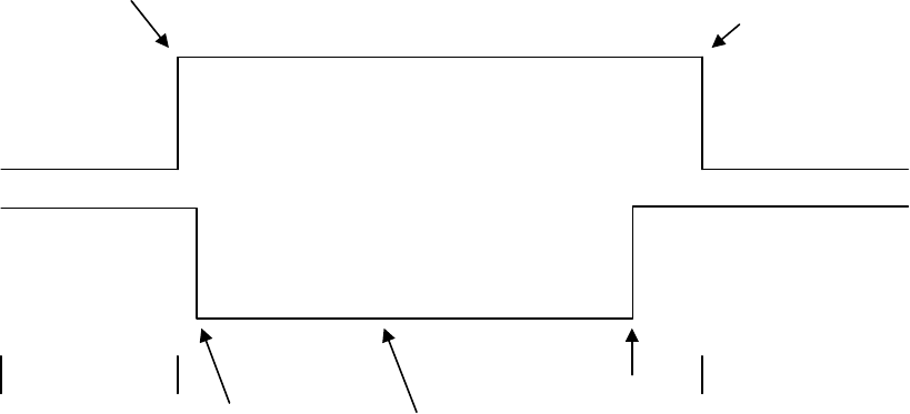
Returning to operation of the REX relay, as we said earlier, it energizes 50 milliseconds before
the lock control transistor releases the lock. It remains energized as long as the lock control
transistor is continuing to release the lock. When the lock resecures, the REX relay will remain
energized for one additional second to allow the magnetic lock to fully engage and report secure
in the event that it is reporting lock status to an access control system.
FIG. 8: OPERATIONAL TIMING CHART FOR XMS
REX RELAY
LOCK CONTROL
TRANSISTOR
NORMAL OPERATION: REX
RELAY DEENERGIZED; LOCK
CONTROL TRANSISTOR "ON"
(CONDUCTING)
OBJECT DETECTED
REX RELAY
ENERGIZES
50 MILLISECONDS AFTER
DETECTION, THE LOCK
CONTROL TRANSISTOR
TURNS OFF, RELEASING THE
LOCK
DETECTION STOPS:
RELAY + TRANSISTOR
MAINTAIN THEIR STATES
LOCK CONTROL TRANSISTOR
RESECURES LOCK AFTER
TIMER RUNS OUT
NORMAL OPERATION: REX
RELAY DEENERGIZED; LOCK
CONTROL TRANSISTOR "ON"
(CONDUCTING)
REX RELAY DEENERGIZES ONE SECOND
AFTER LOCK RESECURES
The four second timing feature of the lock control relay can be altered by changing jumper
settings (see Section 5) but the REX relay always operates 50 milliseconds before and one
second after the lock control transistor. Figure 8 shows the timing sequences.
5. JUMPER SETTINGS
Refer to Figure 2 and note that there are 3 jumpers. They are depicted in factory set condition.
The LED logic jumper controls the logic of the bi-color LED. When left in factory set position
(jumper installed), the LED will illuminate red during a detection event and return to green in
the rest condition. Removing the jumper will reverse these colors.
The sensitivity jumper makes the unit sensitive to movement in the factory set condition
(jumper installed). It will become less sensitive when the jumper is removed. This is
sometimes advised when the unit is mounted with a loosely fitting door that leads to the exterior
of the building. If air, at a different temperature from the interior, is able to blow in
from the gaps in the loosely fitting door, the XMS may “see” this. The lock will therefore
be occasionally released with no one present. Removal of the jumper can correct the problem at
the cost of a bit slower operation. Other techniques include physically locating the unit farther
from the edges of the door and adding weather-stripping to the door.
PN# 500-18000
Page 7 Rev. D, 10/11
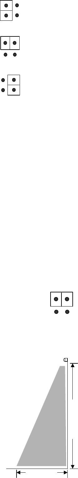
The time set jumper can be installed in any of three positions to
alter the factory set trailing edge delay of four seconds. The drawing
to the right shows the three choices. Four seconds is right for most
applications. 1/2 second is used for pattern set-up (see Section 6)
and certain applications where an external timer should replace the
XMS timer. For example, when the XMS is integrated with an
access control system (see Section 3.4), the XMS’s REX relay will
trigger the access system’s lock control relay and the magnetic lock
will release for the same amount of time that is programmed for
entry. If the set jumper is installed for the 1/2 second setting and
assuming a person is initially sensed by the XMS, then does not
immediately exit but moves around in front of the door, they will
continue to retrip the XMS. Persistant retripping of the XMS however,
will cause the Lock Control and REX Relay to remain latched until no movement is sensed for a
time greater than the set 1/2 second. It is important to note that this device has a “trailing
edge” delay – i.e. the device Lock Control and REX Relay will remain latched until a time
greater than the set time has expired since the last detected movement. If you used the
four second setting on the XMS for integration with an access control system, you would risk the
following problem. On initial detection, the access system starts timing for 10 seconds (as an
example) But the person does not immediately exit but moves around in front of the door so
that the XMS signal does not change but stays closed because of the four second timing
function. This allows the access system’s 10 second timer to time out and if the door is then
used, a “forced door” alarm signal will result. So the 1/2 second setting is right for integration
with access control systems.
Another application where you should employ the 1/2 second setting is when the XMS is
employed to initiate delayed exit when you are using Securitron’s model XDT timer.
The eight second setting is rarely used unless there is strong concern for maximum time being
allocated for egress even when movement is not maintained. The problem with an eight second
trailing edge delay is that entry security begins to be compromised by the door remaining open
for this length of time following exit.
6. DETECTION PATTERN SET-UP
At this point in the installation, the unit should be physically mounted and wired.
You should have also considered changing the jumper settings. Your final step is to
adjust the detection pattern for the optimum combination of egress safety and entry
security. Before doing this, set the time set jumper to the 1/2 second position
(shown in the drawing to the right). As you are adjusting the pattern, you will make
many quick tests of the unit and this will be most efficient if you don’t have to wait for a four or
eight second trailing edge timer to expire.
The XMS provides two means of adjustment. First, the entire barrel
assembly rotates 90 degrees so that the unit can look “out” or “down”.
Second, aiming screws (see Figure 2) are provided to laterally control the
pattern. To access the aiming screws, the barrel assembly must be
rotated so that the unit looks “out” so while you are making these
adjustments, you will need the barrel locking screw (see Figure 2) to be
loose.
In most applications, the unit is set to look “down”. The exception would
be if the XMS was mounted on a wall perpendicular to the door rather
than parallel to it. As the detection pattern proceeds outward from the
XMS it spreads. We are talking here about spreading in the same
direction as the barrel rotation rather than lateral spreading which is
constrained by the aiming screws. The drawing on the right provides an
example of this spreading. Assuming the XMS is mounted seven feet
above the floor, the pattern will spread out roughly three feet by the time it reaches the floor.
Maximum detection distance is approximately 20 feet.
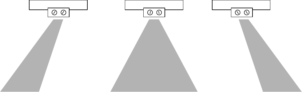
The aiming screws are used as follows. They control internal louvers that point the same way
as the slots in the screws. When adjusting these screws, do not turn them past the point where
AB
AB
AB
FOUR SECONDS
FACTORY SET
1/2 SECOND
8 SECONDS
AB
3 FT. (1 M)
7 FT. (2.1 M)
PN# 500-18000
Page 8 Rev. D, 10/11
you feel resistance as they can take the louvers “off track”. Figure 9 shows the typical
relationship between the aiming screw orientation and the resultant detection pattern.
To set your pattern laterally, experiment with the aiming screws as is shown in Figure 9. Each
time you alter the aiming screw setting, you will have to rotate the barrel assembly up and
down. Test the pattern by moving in it and observing the limits of detection by watching the
LED. When you are satisfied with the aiming screw settings, you must also finalize the degree of
barrel assembly rotation. You don’t want the unit “seeing” the surface of the door itself as this
can lead to false detection, so in the common case where the unit mounts in the same plane as
the door, you do not want the barrel assembly adjusted at full 90 degrees. It should face
slightly away from the door.
When you are entirely satisfied, be sure to tighten the barrel locking screw and restore the time
set jumper to the four second position (if necessary). Then replace the cover.
FIG 9: USE OF THE AIMING SCREWS
7. MAGNACARE LIFETIME REPLACEMENT WARRANTY
For warranty information visit: www.securitron.com/en/site/securitron/About/MagnaCare-Warranty/
