Security V672B W312Mir Manual Instruction User
2017-11-03
User Manual: Security V672B-W312Mir Manual V672B-W312MIR_Manual uploads wp-content
Open the PDF directly: View PDF ![]() .
.
Page Count: 24
V672B HD Analog Bullet Cameras
Installation and Operation Guide
Vicon Industries Inc. does not warrant that the functions contained in this equipment will
meet your requirements or that the operation will be entirely error free or perform
precisely as described in the documentation. This system has not been designed to be
used in life-critical situations and must not be used for this purpose.
Document Number: 8009-8299-30-00 Product specifications subject to change without
notice. Issued: 2/17 Copyright © 2017 Vicon Industries Inc. All rights reserved.
Vicon Industries Inc.
Tel: 631-952-2288) Fax: 631-951-2288
Toll Free: 800-645-9116
24-Hour Technical Support: 800-34-VICON
(800-348-4266) UK: 44/(0) 1489-566300
www.vicon-security.com
XX299-30

2
FCC COMPLIANCE STATEMENT
CE COMPLIANCE STATEMENT
This device complies with Part 15 of the FCC Rules. Operation is subject to the following
two conditions: (1) this device may not cause harmful interference, and (2) this device
must accept any interference received, including interference that may cause undesired
operation.
FCC INFORMATION: This equipment has been tested and found to comply with the
limits for a Class A digital device, pursuant to Part 15 of the FCC Rules. These limits
are designed to provide reasonable protection against harmful interference when the
equipment is operated in a commercial environment. This equipment generates, uses,
and can radiate radio frequency energy and, if not installed and used in accordance
with the instruction manual, may cause harmful interference to radio communications.
Operation of this equipment in a residential area is likely to cause harmful interference
in which case the user will be required to correct the interference at his own expense.
CAUTION: Changes or modifications not expressly approved by the party
responsible for compliance could void the user’s authority to operate the equipment.
WARNING: This is a Class A product. In a domestic environment this product may
cause radio interference in which case the user may be required to take adequate
measures.

3
IMPORTANT SAFETY INSTRUCTIONS
1. Read these instructions.
2. Keep these instructions.\
3. Heed all warnings.
4. Follow all instructions.
5. Do not block any ventilation openings. Install in accordance with the manufacturer’s
instructions.
6. Do not install near any heat sources such as radiators, heat registers, stoves, or other
apparatus (including amplifiers) that produce heat.
7. Only use attachments/accessories specified by the manufacturer.
8. Use only with the cart, stand, tripod, bracket, or table specified by
The manufacturer, or sold with the apparatus. When a cart is used,
Use caution when moving the cart/ apparatus combination to avoid
Injury from tip-over.
9. CAUTION – THESE SERVICING IN STRUCTIONS ARE FOR USE BY QUALIFIED
SERVICE PERSONNEL ONLY. TO REDUCE THE RISK OF ELECTRIC SHOCK DO
NOT PERFORM ANY SERVICING OTHER THAN THAT CONTAINED IN THE
OPERATING INSTRUCTIONS UNLESS YOU ARE QUALIFIED TO DO SO.
10. Use satisfy clause 2.5 of IEC60950-1/UL 60950-1 or Certified/Listed Class 2
power source only.
11. Indoor use only.
EXPLANATION OF GRAPHICAL SYMBOLS
The lighting flash with arrowhead symbol, within an equilateral triangle, is
Intended to alert the user to the presence of uninsulated “dangerous voltage”
within the product`s enclosure that may be of sufficient magnitude to constitute
a risk of electric shock to persons.
The exclamation point within an equilateral triangle is intended to alert the user
to the presence of important operating and maintenance (servicing)
instructions in the literature accompanying the appliance.
LIMITATION OF LIABILITY
THE INFORMATION IN THIS PUBLICATION IS BELIEVED TO BE ACCURATE IN ALL
RESPECTS; HOWEVER, WE CANNOT ASSUME RESPONSIBILITY FOR ANY
CONSEQUENCES RESULTING FROM THE USE THEREOF. THE INFORMATION
CONTAINED HEREIN IS SUBJECT TO CHANGE WITHOUT NOTICE. REVISIONS OR
NEW EDITIONS TO THIS PUBLICATION MAY BE ISSUED TO INCORPORATE SUCH
CHANGES.
4
PRECAUTIONS
Before installation, carefully read the manual to ensure correct operation and setup,
heeding all warnings and instructions.
Do not block any ventilation openings. Install in accordance with the manufacturer's
instructions.
Ensure manual is kept in good condition for future use.
Do not install the device near any heat sources such as radiators, heat registers, stoves,
or other equipment(including amplifiers) that produce heat.
Only use attachments/accessories specified by the manufacturer.
Should any liquid get into the housing, immediately disconnect the device from the power
supply and have it checked by authorized personnel before reusing.
Do not install the device in a place where it is exposed to gas or oil.
Installation and servicing by authorized personnel only, adhering to local safety
regulations.
Unless you are an authorized technician, never try to dismantle the device. To avoid
electric shock, never remove the screws or covers.
If a camera, do not expose the device to radioactivity. It will cause serious damage to the
CCD.
Use Certified/Listed Class 2 power source only.
Cleaning
Clean the device with a slightly damp soft cloth. Use a mild household detergent. Never
use strong solvents such as thinner or benzene as they might damage the finish of the
unit.

5
TABLE OF
CONTENTS
INTRODUCTION -------------------------------------------------------------------------- 6
CAMERA CONNECTION --------------------------------------------------------------- 7
LENS ADJUSTMENT -------------------------------------------------------------------- 7
CONTENTS OF PACKAGE ------------------------------------------------------------ 8
INSTALLATION ---------------------------------------------------------------------------- 8
STRUCTURE OF THE SETUP MENU ----------------------------------------------- 9
DC AUTO IRIS LENS ------------------------------------------------------------------- 15
SPECIFICATIONS ----------------------------------------------------------------------- 16
EXTERNAL DIMENSION ------------------------------------------------------------ 18

6
INSTRUCTION
The 1/2.8” 2.1M Full HD CMOS camera, especially for closed circuit television
CCTV and security surveillance application.
Features:
• High performance SONY 1/2.8” 2.1M STARVIS CMOSTM
• Min. illumination 0.03 lux (Color), 0 lux(BW, IR LED ON)
• Auto electronic shutter [1/30 (1/25) ~ 1/30,000] and manual electronic shutter
modes
• True WDR (Wide Dynamic Range) in HD mode
• D-WDR (Digital Wide Dynamic Range) in composite mode
• BLC (Back-light compensation)
• HLC (High-light compensation)
• Auto and manual white balance modes (AUTO/AUTOext/Manual/AWB)
• Day & Night (ICR): Auto/Color/BW/EXTERN
• OSD (on screen display)
• DNR (Digital Noise Reduction)
• IR Range distance up to 130 ft/40 m
• 42EA, 850nm IR LEDs
• Privacy Mask function (16 zones)
• Motion Detection (4 zones)
• Defog
• Composite Video Output (700TV Lines)
• Operates in 24 VAC ± 10%/12 VDC ± 10%
• Use Certified / Listed Class 2 Power source only
IMPORTANT: The user of this camera is responsible for checking and
complying with local, state, and federal laws and statutes concerning the
recording and monitoring of audio signals.
7
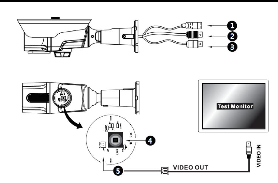
CAMERA CONNECTION
① Power: 24 VAC/12 VDC power source from a 12 VDC or 24 VAC ±10%,
60/50Hz±1Hz; use Certified/Listed Class 2 power source only.
12 VDC Type => 12 VDC ±10% (12 VDC is polarity dependent)
If using 12 VDC power adaptor, use power supply capable of supplying 8 Watts.
② Video (HD): BNC (Black) connector used to connect the camera to a DVR, etc.
③ Video (CVBS): BNC (Yellow) connector used to connect the camera to a
DVR, etc.
④ Tact Switch for OSD control
⑤ SPOT: Spot connector used to check video(CVBS) output.
8
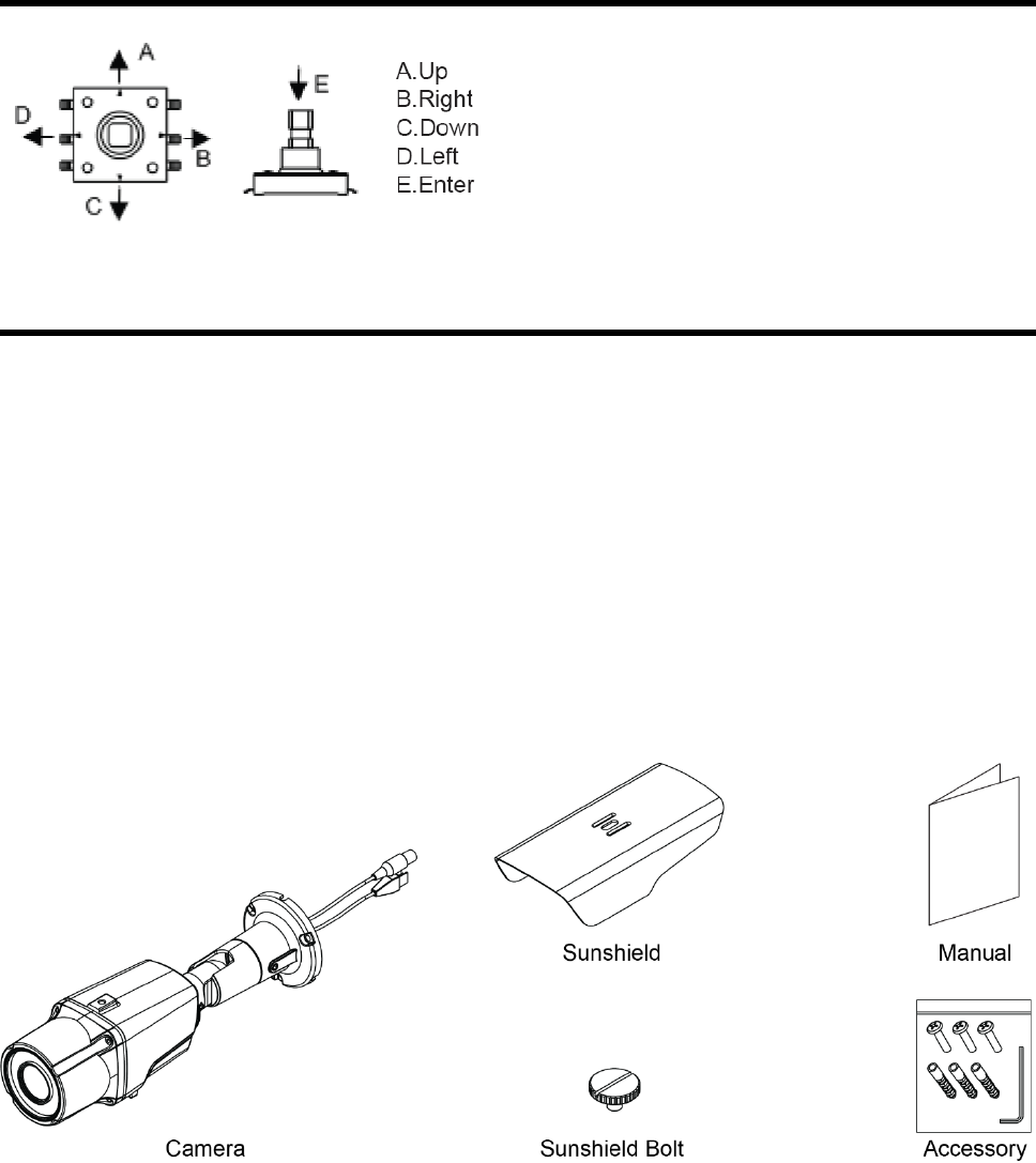
LENS ADJUSTMENT
Tact Switch for motorized lens control
without being in the OSD:
Up – Zoom in
Down – Zoom out
The lens will then autofocus the lens
based on the overall scene being viewed.
CONTENTS OF PACKAGE
Installation of the camera must be performed by qualified service personnel in
accordance with all local and national electrical and mechanical codes.
Carefully remove the color camera and its accessories from the carton and verify that
they were not damaged in shipment.
The content of the package includes:
1. Camera in housing
2. This manual
3. Accessory kit for installing
4. Sunshield Bolt
5. Sunshield
9
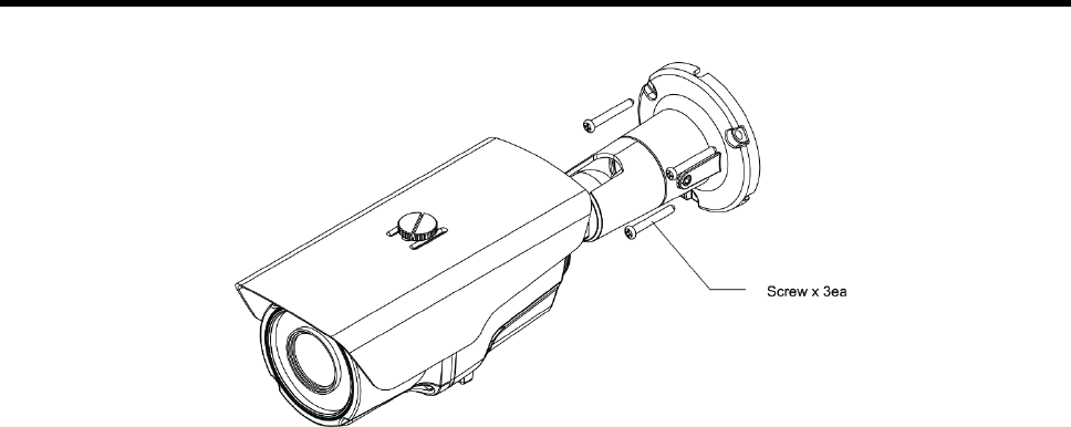
INSTALLATION
CAUTION
Adjusting the position of the camera after installation could potentially damage the cable.
10
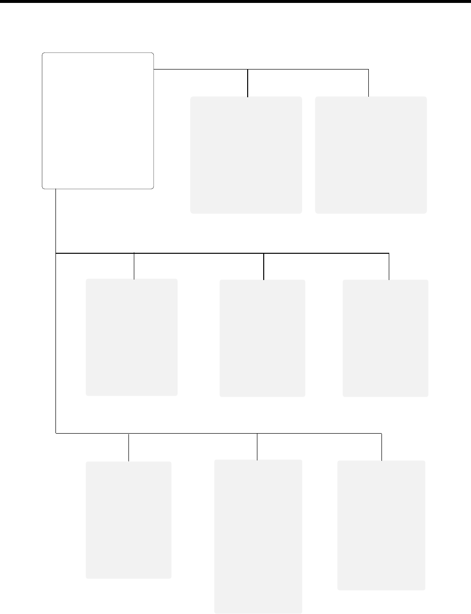
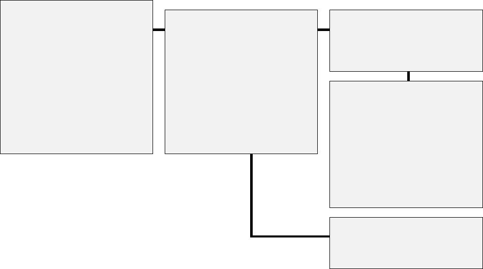
STRUCTURE OF THE SETUP MENU
<MENU>
FOCUS SETUP
EXPOSURE
BACKLIGHT
DAY&NIGHT
AWB
DNR
IMAGE
SYSTEM
EXIT
<FOCUS SETUP>
AF MODE
SCANNING
ONPUSHAF
SYNC TDN
INITIAL
RETURN
<EXPOSURE>
IRIS
BRIGHTNESS
SHUTTER
SENS-UP
AGC
RETURN
<BACKLIGHT>
OFF
HLC
BLC
WDR
<DAY&NIGHT>
EXTERN
AUTO
COLOR
B&W
<AWB>
AUTO
AUTOext
PRESET
MANUAL
<DNR>
OFF
LOW
MIDDLE
HIGHT
<IMAGE>
COLOR GAIN
SHARPNESS
GAMMA
MIRROR
FLIP
D-WDR
DEFOG
PRIVACY
MOTION
RETURN
<SYSTEM>
OUTPUT
FRAME RATE
FREQ
LANGUAGE
SETUP
RESET
RETURN

11
FOCUS SETUP
The FOCUS SETUP menu provides the ability to adjust the AF MODE, SCANNING,
ONEPUSHAF, SYCN TDN and INIT functions of the camera.
1) AF MODE: Auto, Manual
2) SCANNING: Select the range of focusing during Auto mode: ▶HALF, FULL
3) ONEPUSHAF: Will focus the camera
4) SYNC TDN: Will refocus when switching between color/B&W and B&W/color:
▶Off/On
5) INIT: Reinitializes the lens
<FOCUS SETUP> Mode
EXPOSURE
The EXPOSURE menu is used to set the automatic light control method for the camera.
It provides the ability to adjust the IRIS, BRIGHTNESS, SHUTTER speed, SENS-UP and
AGC functions of the camera.
1) IRIS: Select the IRIS mode: ▶ALC (DC), ELC (Manual)
2) BRIGHTNESS: Adjust the BRIGHTNESS level: ▶0 - 20
3) SHUTTER: Select the SHUTTER speed level:
▶Auto (INDOOR, OUTDOOR, DEBLUR),
MANUAL 1/30 (25) - 1/30000, FLICKER
4) SENS-UP: Select the Digital Slow Shutter level: ▶OFF, x2 ~ x32
5) AGC: Adjust the Auto Gain Control level: ▶0 - 10
MAIN MENU
FOCUS SETUP
▶ FOCUS SETUP
EXPOSURE
AF MODE
AUTO
BACKLIGHT
OFF
SCANNING
HALF
DAY&NIGHT EXTERN ONEPUSHAF ON ↓
AWB
AUTO
SYNC TDN
OFF
DNR LOW INITIAL ON ↓
IMAGE
RETURN
SYSTEM
EXIT

12
<EXPOSURE> Mode
BACKLIGHT
The BACKLIGHT menu is used to the ability to prevent back lighting from the image.
1) HLC: Improves the ability to identify subjects in brightly lit situations by filtering out
(masking) the strength of the light. Mask the high light zone with specific color and
level.
LEVEL Select the HLC level: ▶0 ~ 20
COLOR Select the HLC area color:
▶BLK, CUSTOMIZE, WHT, YEL, CYN, GRN, MAG, RED, BLU
2) BLC: Compensates for a loss of detail on dark subjects due to backlighting by
providing increased brightness on the overall scene. Adjust the position and size of
Back Light Compensation area.
H-POS Adjust the BLC area window horizontal position: ▶0 - 20
V-POS Adjust the BLC area window vertical position: ▶0 - 20
H-SIZE Adjust the BLC area window horizontal size: ▶0 - 20
V-SIZE Adjust the BLC area window vertical size: ▶0 - 20
3) WDR Expands the dynamic range light effect to secure a clear image under All
illumination environments. True WDR in HD mode only.
MODE Select the WDR area ▶ NORMAL, ROI
WEIGHT Adjust the WDR level ▶ LOW, MIDDLE, HIGH
Note:
When CVBS video is connected, the DNR function cannot be turned on.
MAIN MENU
SHUTTER
EXPOSURE
FOCUS SETUP
MODE INDOOR
▶ EXPOSURE IRIS ALC RETURN
BACKLIGHT OFF BRIGHTNESS 10 ┃-----┃
DAY&NIGHT
EXTERN
SHUTTER
AUTO
AWB
AUTO
SENS-UP
x4
DNR LOW AGC 7 ┃-----┃
IMAGE
RETURN
SYSTEM
EXIT

13
<BACK LIGHT> Mode
DAY&NIGHT
The DAY&NIGHT menu is used to configure how the camera handles color and changes
between the day and night modes.
1) EXTERN
ANTI-SAT. Adjust levels of anti-saturation: ▶0 - 20
EXTERN SW Adjust levels of External sensor: ▶LOW, HIGH
D>N THRES Adjust levels of day to night transition: ▶0 - 20
N>D THRES Adjust levels of night to day transition: ▶0 - 20
DELAY Adjust time of D&N change ▶ LOW, MIDDLE, HIGH
2) AUTO
ANTI-SAT. Adjust levels of anti-saturation: ▶ 0 - 20
AGC THRES Adjust levels of transition: ▶0 - 20
AGC MARGIN Adjust levels of transition: ▶0 - 20
DELAY Adjust time of day and night mode transition
▶LOW, MIDDLE, HIGH
DAY&NIGHT mode are changed according to the brightness of the image. Use only when
the camera is installed in a dark place but the camera is viewing a bright place.
When used in a normal installation, hunting may occur.
3) COLOR
Select color to have the camera to display in color.
4) B&W
ANTI-SAT. Adjust levels of anti-saturation: ▶0 - 20
MAIN MENU
HLC
BLC
FOCUS SETUP
EXPOSURE
LEVEL 10 ┃-----┃ H-POS 8
▶ BACKLIGHT OFF
COLOR BLK V-POS 7
DAY&NIGHT
EXTERN
RETURN
H-SIZE
3
AWB
AUTO
V-SIZE
3
DNR
LOW
RETURN
IMAGE
SYSTEM
EXIT
WDR
MODE
NORMAL
WEIGHT
MIDDLE
RETURN

14
<DAY & NIGHT> Mode
AWB
The screen color can be adjusted by using the Auto White Balance function. This
compensates for deviations in the white color caused by changes in the color temperature
of the light source so that the colors are reproduced correctly.
1) AUTO Automatically adjust indoor color temperature.
2) AUTOext Automatically adjust outdoor color temperature.
3) PRESET Automatically readjust only by a simple press and hold until the
desired auto white level is reached.
4) MANUAL Manual mode. User can change color temperature, Red and Blue gain
value manually.
C-TEMP 3000°K, 5000°K, 8000°K
R-GAIN 0 ~ 20
B-GAIN 0 ~ 20
<WHITE BALANCE> Mode
MAIN MENU
EXTERN
AUTO
FOCUS SETUP
EXPOSURE
ANTI-SAT. 5 ┃-----┃ ANTI-SAT. 5 ┃-----┃
BACKLIGHT OFF
EXTERN SW LOW AGC THRES 10┃-----┃
▶ DAY&NIGHT EXTERN
D>N THRES 4 ┃-----┃ AGC MARGIN 10┃-----┃
AWB AUTO
N>D THRES 5 ┃-----┃ DELAY LOW
DNR LOW
DELAY LOW RETURN
IMAGE
RETURN
SYSTEM
EXIT
B&W
ANTI-SAT. 5 ┃-----┃
RETURN
MAIN MENU
MANUAL
FOCUS SETUP
EXPOSURE
C-TEMP
5000K
BACKLIGHT OFF
R-GAIN 10 ┃-----┃
DAY&NIGHT EXTERN
B-GAIN 10 ┃-----┃
▶ AWB AUTO
RETURN
DNR
LOW
IMAGE
SYSTEM
EXIT
15
DNR
The DNR menu provides the ability to adjust the DNR (Digital Noise Reduction) functions
of the camera.
1) DNR: Select DNR: ▶LOW, MIDDLE, HIGH
Note:
When CVBS video is connected, the DNR function cannot be turned on.
IMAGE
The IMAGE menu provides the ability to adjust the COLOR GAIN, SHARPNESS,
GAMMA, MIRROR, FLIP, D-WDR, DEFOG, PRIVACY and MOTION functions of the
camera.
1) COLOR GAIN Adjust the COLOR GAIN level: ▶0 - 20
2) SHARPNESS Adjust the SHARPNESS level: ▶0 - 10
3) GAMMA Select the gamma level: ▶0.45, 0.55, 0.65, 0.75
4) MIRROR Select mirror mode: ▶ON, OFF
5) FLIP Select flip mode: ▶ ON, OFF
6) D-WDR Select the Digital WDR: ▶OFF, LOW, MIDDLE, HIGH
For composite video.
7) DEFOG Select the DEFOG mode.▶ OFF, ON
MODE: ▶AUTO, MANUAL
LEVEL: ▶LOW, MIDDLE, HIGH
8) PRIVACY Hide an area of a scene the user does not want to display: ▶OFF, ON
ZONE NUM Select the privacy zone: ▶AREA0 - AREA15
ZONE DISP Select the privacy zone display: ▶OFF, ON
H-POS Select the privacy zone horizontal position: ▶0 - 60
V-POS Select the privacy zone vertical position: ▶0 - 34
H-SIZE Select the privacy zone horizontal size: ▶0 - 60
V-SIZE Select the privacy zone vertical size: ▶0 - 34
Y LEVEL Select the privacy zone darkness: ▶0 - 20
CB LEVEL Select the privacy zone blue color: ▶0 - 20
CR LEVEL Select the privacy zone red color: ▶0 - 20
TRANS Select the privacy zone transparency: ▶0 - 3
9) MOTION Select an area to detect motion object in the scene: ▶ ON, OFF
DET WINDOW Select the motion area: ▶AREA1 - AREA4

16
DET TONE Select the motion area transparency: ▶0 - 3
MDRECT FILL Select how the motion area is displayed: ▶ON, OFF
When On, the motion area box fills with transparent red
when motion is detected; when Off, the box will just have
a border.
SENSITIVITY Adjust the motion sensitivity level: ▶0 - 10
MOTION OSD Select the motion OSD: ▶ON, OFF
TEXT ALARM Select the motion text display: ▶ON, OFF
<IMAGE> Mode
SYSTEM
The SYSTEM menu provides the ability to adjust the OUTPUT, FRAME RATE, FREQ,
LANGUAGE, SETUP and RESET functions of the camera.
1) OUTPUT Select the output mode.
MAIN OUTPUT: ▶ANALOG HD, ANALOG OUT
ANALOG HD: ▶TVI, HD-A
ANALOG OUT: ▶CVBS
Y GAIN Adjust the Y gain: ▶0 ~ 255
MAIN MENU
SHARPNESS
IMAGE
MAIN OUTPUT ANALOG HD
FOCUS SETUP
ANALOG HD
TVI
EXPOSURE COLOR GAIN 10 ┃-----┃ CVBS 5 ┃-----┃
BACKLIGHT OFF SHARPNESS
TVI 5 ┃-----┃
DAY&NIGHT EXTERN GAMMA 0.55 HD-A 5 ┃-----┃
AWB
AUTO
MIRROR
OFF
DNR
LOW
FLIP
OFF
▶ IMAGE D-WDR OFF DEFOG
SYSTEM
DEFOG OFF MODE AUTO
EXIT
PRIVACY
OFF
LEVEL
MIDDLE
MOTION
OFF
RETURE
RETURN
PRIVACY
ZONE NUM
0
ZONE DISP
ON
H-POS
12
V-POS
2
H-SIZE
3
V-SIZE
3
Y LEVEL 10 ┃-----┃
CB LEVEL 10 ┃-----┃
CR LEVEL 10 ┃-----┃
TRANS
0
RETURE
MOTION
DET WINDOW
DET TONE
2
MDRECT FILL
ON
SENSITIVITY 5 ┃-----┃
MOTION OSD
ON
TEXT ALARM
ON
RETURN
17
CB GAIN Adjust the CB gain: ▶0 ~ 255
CR GAIN Adjust the CR gain: ▶0 ~ 255
POSITION Adjust the position: ▶0 ~ 255
BURST FREQ Adjust the burst frequency: ▶0 ~ 255
BURST GAIN Adjust the burst gain: ▶0 ~ 255
B&W Select the B&W mode burst on/off: ▶BURST ON, BURST OFF
TVI_UTC Select the TVI_UTC Protocol: ▶ Hikvision-C, Pelco-C
(UTC – Up the Coax)
2) FRAME RATE Select the frame rate: ▶1080 30P, 720 30P, 720 60P
3) FREQ Select the frequency: ▶60HZ, 50HZ
4) LANGUAGE OSD menu LANGUAGE: ▶ ENG, CHN, CHN(S), JPN, KOR
5) SETUP Set the camera version.
CAM VERSION: Select the camera version
SAVE: Save the user setting value
6) RESET Factory initialization of camera settings
<SYSTEM> Mode
MAIN MENU
OUTPUT
SYSTEM
FOCUS SETUP
MAIN OUTPUT
ANALOG HD
EXPOSURE
OUTPUT
ANALOG HD
TVI
BACKLIGHT
OFF
FRAME RATE
1080 30P
ANALOG OUT
CVBS
DAY&NIGHT
EXTERN
FREQ.
60HZ
RETURN
AWB
AUTO
LANGUAGE
ENG
DNR LOW
SETUP
HD-ANALOG
IMAGE
RESET ON ↓ ANALOG HD TVI
▶ SYSTEM
RETURN Y GAIN 17 ┃-----┃
EXIT
CB GAIN 80 ┃-----┃
CR GAIN 90 ┃-----┃
POSITION 128┃-----┃
BURST FREQ 128┃-----┃
BURST GAIN 90 ┃-----┃
B&W
BURST OFF
TVI_UTC
Hikvison-C
RETURN
SETUP
CAM VERSION
710A(1306)
SAVE ON ↓
RETURN
18
DC AUTO IRIS LENS
Image Size
1/2.8” CMOS
Focal Length
2.8-12mm
Aperture Ratio
1:1.2
Angular
Field of View
DIAGONAL
2.8mm : 103º
12mm : 30º
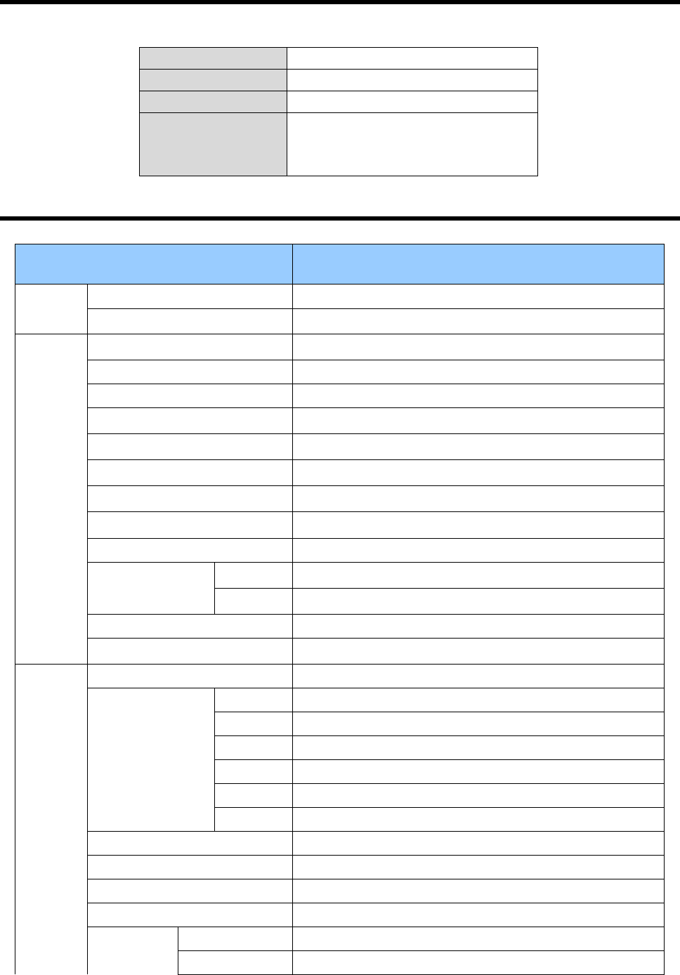
SPECIFICATION
MODEL V672B-W312MIR
Power Power Source 24 VAC ± 10%/12 VDC ± 10%
Power Consumption Max 7.5 Watts (630mA)
General
Image Sensor 1/2.8" 2.1M Sony CMOS
Total Pixels 1945 (H) x 1109 (V)
Active Pixels 1937 (H) x 1097 (V)
Scanning System 16:9 Progressive
Sync. System Internal
Video Frame Rate 1920×1080p@30 fps1920×1080p@25 fps
CVBS Resolution 700TVL
Min. illumination 0.03 lux (COLOR) at DSS off, 0 lux (BW, IR LED ON)
Video Output BNC 1 (TVI/AHD selectable)/ NC 2 (CVBS)
IR IR LED 42ea IR LEDs (850nm)
DISTANCE 130 ft/ 40 m
Camera Control OSD Menu (joystick switch, coaxial control)
S/N Ratio More than 52dB (AGC off)
Function
Lens DC (ALC)/MANUAL (ELC)
Exposure
Shutter AUTO/FLICKER/MANUAL (1/30 (25)~1/30,000 sec)
AGC 1 ~ 10
Sens-UP OFF/x2/x4/x8/x16/x32
Brightness 1 ~ 20
D-WDR OFF/ON (composite mode)
Defog OFF/ N
Backlight OFF/HLC/BLC/WDR (true WDR in HD mode)
White Balance AUTO (Indoor)/AUTOext(Outdoor)/PRESET/MANUAL
Day & Night AUTO/COLOR/B&W EXTERN
DNR OFF/LOW/MIDDLE/HIGH
S
P
E
Sharpness 0 ~ 10
Mirror OFF/ON

19
C
I
A
L
Flip OFF/ON
Shading OFF/ON
Motion Detection OFF/ON (4 zones)
Privacy Masking OFF/ON (16 zones)
Language ENG/CHN/CHN(S)/JPN/KOR
Video mode 60Hz (NTSC)/50Hz (PAL)
AF
AF Mode AUTO/MANUAL
Scanning HALF/FULL
One Shot AF Enter
SYNC TDN OFF/ON
Lens Initialize Enter
EXIT EXIT (Auto Save)
Connector
&
ETC
Power input Terminal Block
Video output BNC 1 Connector (TVI/AHD)/BNC 2 Connector (CVBS)
Transmission Distance Over 500m via 5C-2V coaxial cable
Lens mount Fixed mount
Lens 2 Motor, f=2.8~12mm F1.4~360 Varifocal, ICR (D&N)
Operating temperature 14°F ~ 122°F (-10℃ ~ +50℃)
Operating humidity 0 ~ 96% (non-condencing)
External dimension 11.8 (D) x 3.9 (H) x 3.4 (W) in (300 x 98.4 x 87mm)
Weight 2.28 lb (1 kg)
Ingress Protection IP66
* Specifications are subject to change without notice *
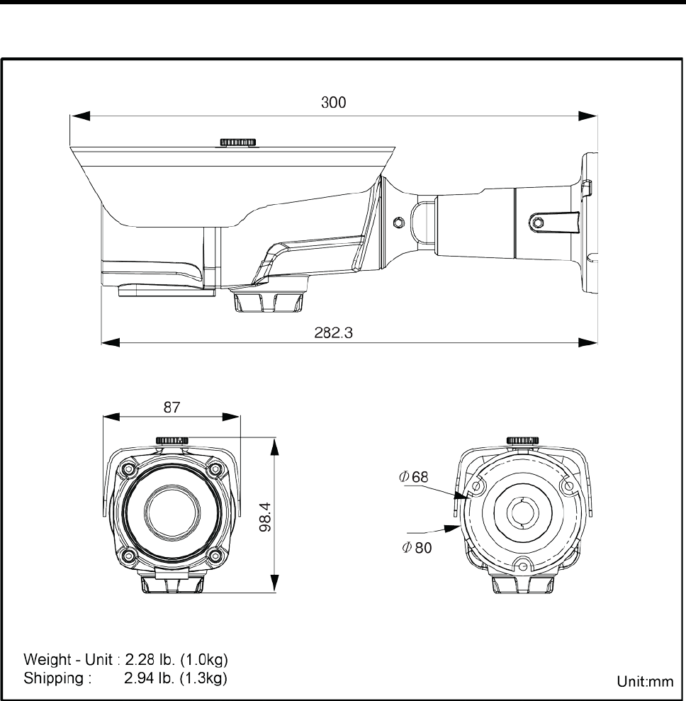
20
EXTERNAL DIMENSION
21
Shipping Instructions
Use the following procedure when returning a unit to the factory:
1. Call or write Vicon for a Return Authorization (R.A.) at one of the locations listed below.
Record the name of the Vicon employee who issued the R.A.
Vicon Industries Inc.
135 Fell Court
Hauppauge, NY 11788
Phone: 631-952-2288; Toll-Free: 1-800-645-9116; Fax: 631-951-2288
For service or returns from countries in Europe, contact:
Vicon Industries Ltd
Unit 4, Nelson Industrial Park,
Hedge End, Southampton
SO30 2JH, United Kingdom
Phone: +44 (0)1489/566300; Fax: +44 (0)1489/566322
2. Attach a sheet of paper to the unit with the following information:
a. Name and address of the company returning the unit
b. Name of the Vicon employee who issued the R.A.
c. R. A. number
d. Brief description of the installation
e. Complete description of the problem and circumstances under which it occurs
f. Unit’s original date of purchase, if still under warranty
3. Pack the unit carefully. Use the original shipping carton or its equivalent for maximum
protection.
4. Mark the R.A. number on the outside of the carton on the shipping label.
22
Vicon Standard Equipment Warranty
Vicon Industries Inc. (the “Company”) warrants your equipment to be free from defects in material and workmanship
under Normal Use from the date of original retail purchase for a period of three years, with the following exceptions:
1. All IQEYE Cameras: Two years if purchased before 1/1/2011.
2. Alliance-mini (IQD3xx), Alliance-mx (IQMxxx) and 3 Series (IQ03xx): Five years if purchased between
1/2/2011 – 12/31/2014.
3. Alliance-Pro (IQA3xx): Five years if purchased between 3/2/2012 – 12/31/2014. Three years if the motorized
lens (IQA3xx-A3) option.
4. Access Control System Components: Two year from date of original retail purchase.
5. Uninterruptible Power Supplies: Two years from date of original retail purchase.
6. VDR-700 Recorder Series: One year from date of original retail purchase.
7. V5616MUX: One year from date of original retail purchase.
8. Arecont Cameras: One year from date of original retail purchase.
9. FMC series fiber-optic media converters and associated accessories: Lifetime warranty.
10. For PTZ cameras, “Normal Use” excludes prolonged use of lens and pan-and-tilt motors, gear heads, and gears
due to continuous use of “autopan” or “tour” modes of operation. Such continuous operation is outside the
scope of this warranty.
11. Any product sold as “special” or not listed in Vicon’s commercial price list: One year from date of original retail
purchase.
NOTE:
• If the product is to be used outdoors or in dusty, humid, or other hostile environments, it must be suitably protected.
• Camera products must be protected, whether in use or not, from exposure to direct sunlight or halogen light as the light
may damage the camera image sensor. This applies to both indoor and outdoor use of the cameras.
• For camera products supplied without a lens, extreme care should be used when mounting a lens on these products.
Damage to the product due to incorrectly mounted lenses will invalidate this limited hardware warranty.
• Failure to comply with any of the aforementioned requirements will invalidate this Limited Hardware Warranty.
Date of retail purchase is the date original end-user takes possession of the equipment, or, at the sole discretion of the
Company, the date the equipment first becomes operational by the original end-user.
The sole remedy under this Warranty is that defective equipment be repaired or (at the Company’s option) replaced, at
Company repair centers, provided the equipment has been authorized for return by the Company, and the return
shipment is prepaid in accordance with policy. Repaired or replacement hardware will be warranted for the remainder of
the original Warranty Period or ninety (90) days, whichever is longer. When a product or part is exchanged the
replacement hardware becomes the property of the original purchaser and all hardware or part thereof that is replaced
shall become the property of Vicon.
The warranty does not apply (a) to faulty and improper installation, maintenance, service, repair and/or alteration in any
way that is not contemplated in the documentation for the product or carried out with Vicon consent in writing, operation
adjustments covered in the operating manual for the product or normal maintenance, (b) to cosmetic damages, (c) if the
product is modified or tampered with, (d) if the product is damaged by acts of God, misuse, abuse, negligence, accident,
normal wear and tear and deterioration, improper environmental conditions (including, but not limited to, electrical
surges, water damage, chemical exposure, an/or heat/cold exposure) or lack of responsible care, (e) if the product has
had the model or serial number altered, defaced or removed, (f) to consumables (such as storage media or batteries) (g)
to products that have been purchased “as is” and Vicon the seller or the liquidator expressly disclaim their warranty
obligation pertaining to the product, (h) to any non-Vicon hardware product or any software (irrespective of packaged or
sold with Vicon hardware product) and Vicon products purchased from an unauthorized distributor/reseller, (i) to damage
that occurs in shipment or (j) to damages by any other causes not related to defective design, workmanship and/or
materials.
The warranty for the products shall run from Vicon to End User customers only (including product purchased through
authorized partners and resellers). Vicon is not obligated under any circumstances to honor warranties on product(s)
purchases from internet auction sites including eBay, uBid or from any other unauthorized resellers. Except as explicitly
provided herein, Vicon disclaims all other warranties, including the implied warranties of fitness for a particular purpose
and merchantability.
Software supplied either separately or in hardware is furnished on an “As Is” basis. Vicon does not warrant that
such software shall be error (bug) free. Software support via telephone, if provided at no cost, may be
discontinued at any time without notice at Vicon’s sole discretion. Vicon reserves the right to make changes to
its software in any of its products at any time and without notice.
The Warranty and remedies provided above are exclusive and in lieu of all other express or implied warranties
including, but not limited to, the implied warranties of merchantability or fitness for a particular purpose. Certain
jurisdictions do not allow the exclusion of implied warranties. If laws under such jurisdictions apply, then all
express and implied warranties are limited to the warranty period identified above. Unless provided herein, any
statements or representations made by any other person or firm are void. Except as provided in this written
warranty and to the extent permitted by law, neither Vicon nor any affiliated shall be liable for any loss,
23
(including loss of data and information), inconvenience, or damage, including, but not limited to, direct, special,
incidental or consequential damages, resulting from the use or inability to use the Vicon product, whether
resulting from breach of warranty or any other legal theory. Notwithstanding the foregoing, Vicon total liability
for all claims under this warranty shall not exceed the price paid for the product. These limitations on potential
liabilities have been an essential condition in setting the product.
No one is authorized to assume any liability on behalf of the Company, or impose any obligations on it in connection with
the sale of any Goods, other than that which is specified above. In no event will the Company be liable for indirect,
special, incidental, consequential, or other damages, whether arising from interrupted equipment operation, loss of data,
replacement of equipment or software, costs or repairs undertaken by the Purchaser, or other causes.
This warranty applies to all sales made by the Company or its dealers and shall be governed by the laws of New York
State without regard to its conflict of laws principles. This Warranty shall be enforceable against the Company only in the
courts located in the State of New York.
The form of this Warranty is effective August 1, 2015.
THE TERMS OF THIS WARRANTY APPLY ONLY TO SALES MADE WHILE THIS WARRANTY IS IN EFFECT. THIS
WARRANTY SHALL BE OF NO EFFECT IF AT THE TIME OF SALE A DIFFERENT WARRANTY IS POSTED ON
THE COMPANY’S WEBSITE, WWW.VICON-SECURITY.COM. IN THAT EVENT, THE TERMS OF THE POSTED
WARRANTY SHALL APPLY EXCLUSIVELY.

VICON INDUSTRIES INC.
For ofce locations, visit the website: www.vicon-security.com
