Security V910Poe V5 Xx137 67 00 Rev 1208 Roughneck V910 Dome Cameras With PoE User Manual
V910Poe V5 Xx137-67-00 V910POE_V5_XX137-67-00 V910POE_V5_XX137-67-00 IandO Products English-US s Collateral
2017-08-09
User Manual: Security V910Poe V5 Xx137-67-00 V910POE_V5_XX137-67-00 uploads wp-content
Open the PDF directly: View PDF ![]() .
.
Page Count: 40
- FCC Notice
- Important Safeguards - Outdoor Use
- Contents
- Quick Installation
- Introduction
- Installation
- Operation
- Maintenance
- Shipping Instructions
- Reference
- Technical Information
- Vicon Standard Equipment Warranty
XX137-67-00
V910V5 IMPACT-RESISTANT
DOME CAMERAS WITH POE
Vicon Industries Inc. does not warrant that the functions contained in this equipment will meet
your requirements or that the operation will be entirely error free or perform precisely as
described in the documentation. This system has not been designed to be used in life-critical
situations and must not be used for this purpose.
Copyright © 2007 Vicon Industries Inc. All rights reserved.
Product specifications subject to change without notice.
Vicon and its logo are registered trademarks of Vicon Industries Inc.
ViconNet and its logo are registered trademarks of Vicon Industries Inc.
Roughneck and Kollector and their logos are trademarks of Vicon Industries Inc.
Pixim is a trademark of Pixim, Inc.
VICON INDUSTRIES INC., 89 ARKAY DRIVE, HAUPPAUGE, NEW YORK 11788
TEL: 631-952-CCTV (2288) FAX: 631-951-CCTV (2288) TOLL FREE: 800-645-9116
24-Hour Technical Support: 800-34-VICON (800-348-4266)
UK: +44 (0) 1489 566300 WEB: www.vicon-cctv.com
Vicon part number 8009-8137-67-00 Rev 1208 Section 3
FCC Notice
Note: Complies with Federal Communications Commission Rules & Regulations Part 15, Subpart B for a Class
A digital device.
WARNING
This equipment generates and uses radio frequency energy and if not installed and used properly, that is, in
strict accordance with the manufacturer’s instruction, may cause interference to radio and television reception. It
has been type tested and found to comply with the limits for a Class A computing device in accordance with the
specification in subpart B of part 15 of the FCC rules, which are designed to provide reasonable protection
against such interference in a commercial installation. However, there is no guarantee that interference will not
occur in a particular installation. If this equipment does cause interference to radio and television reception,
which can be determined by turning equipment off and on, the user is encouraged to try and correct the
interference by one or more of the following measures:
• Reorient the receiving antenna.
• Relocate the equipment with respect to the receiver.
• Relocate the equipment away from the receiver.
• Plug the equipment into a different electrical outlet so that the equipment and receiver are
on different branch circuits.
If necessary, the user should consult the dealer or an experienced radio/television technician for additional
suggestions.
The user may find the following booklet prepared by the Federal Communications Commission helpful:
“Interference Handbook, Bulletin CIB-2”
This booklet is available from the U.S. Government Printing Office, Superintendent of Documents, Mailstop
SSOP, Washington, D.C. 20402-9328, ISBN 0-16-045542-1.
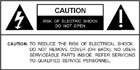
Warning: Power must be removed from this unit before removing circuit modules or ribbon cables.
Caution: This unit contains circuit cards with integrated circuit devices that can be damaged by static
discharge. Take all necessary precautions to prevent static discharge
Important Safeguards - Outdoor Use
GRAPHIC SYMBOL EXPLANATION
The lightening bolt symbol alerts the user to the presence of
dangerous voltage that may present the risk of electric shock.
The exclamation point symbol alerts the user to the presence of
important operating and maintenance instructions.
1. Read Instructions - Read all safety and operating instructions
before the product is operated.
2. Retain Instructions - Retain all safety and operating
instructions for future reference.
3. Heed Warnings - Pay attention to all product warnings.
4. Follow Instructions - Follow all operating instructions.
5. Cleaning -(Do not use caustic, abrasive or aerosol
cleaners)
a) For units that CAN BE DISCONNECTED from the power
source, use a damp cloth for cleaning.
b) For units that CANNOT BE DISCONNECTED from the
power source, use a damp cloth for cleaning and do not
allow moisture or liquids to enter vents.
6. Attachments - Use only UL Listed Vicon recommended
attachments to prevent unit damage and personal injury.
7. Water and Moisture - Use only products designed for outdoor
environments where they will be exposed to water or moisture.
8. Accessories - Do not place the unit on an unstable surface to
avoid falling. Use only UL Listed Vicon recommended mounting
accessories.
9. Ventilation - Do not block ventilating slots and openings as
they ensure reliable operation. Do not place the unit near a heat
source or into an enclosure unless recommended by Vicon.
10. Power Sources - The product should only be operated from
the recommended power source. Use only a UL Class 2
indoor/dry or Class 3 outdoor/wet power supply.
11. Grounding - Only products equipped with a 3-prong
grounded plug should be inserted into a grounded power outlet.
Contact an electrician to replace an obsolete outlet. Do not force
a plug into a non-grounded outlet.
12. Power Cord Protection - Power supply cords should not be
routed in trafficked areas or in tight spaces where they will be
pinched or used to bear weight. Allow some slack in the cord
where it enters the unit.
13. Outdoor Cable Grounding - Use only grounded outdoor
cables to protect against voltage surges and static charges.
Section 810 of the National Electrical Code, ANSI/NFPA 70-
1984, provides information on proper grounding of the lead-in
wire to an antenna discharge unit, size of grounding conductors
and the requirements of grounding electrodes.
14. Lightning - Disconnect the product from its power source
and cable system when possible to prevent damage due to
lightning and power-line surges.
15. Power Lines - Do not locate outside cables over power or
utility lines where they can fall and make direct contact. Contact
with power lines can be fatal.
16. Overloading - Do not overload wall outlets and extension
cords to prevent risk of fire and electric shock.
17. Object and Liquid Entry - Never probe through, or spill
liquid into, enclosure openings to prevent risk of fire or electric
shock.
18. Servicing - Refer all servicing to qualified service personnel.
19. Damage Requiring Service - Obtain service when:
a) The power-supply cord or plug is damaged.
b) Objects have fallen or liquid has been spilled into the
product.
c) The product is not designed for outdoor use and has been
exposed to water or moisture.
d) The product does not operate per the operating instructions.
Perform Vicon recommended adjustments, modifications
and troubleshooting only to avoid unit damage and personal
injury.
e) The product has been dropped.
f) The product shows a significant change in performance.
20. Replacement Parts - Use only Vicon specified replacement
parts or an approved equivalent to prevent unit damage and
injury.
21. Safety Check - Request safety checks to be performed
following repair or maintenance to verify proper operation.
22. ESD Precaution - Take all normal electrostatic discharge
precautions to avoid component damage during installation and
operation.
23. For 230 VAC Devices Only - When the disconnect device is
not incorporated in the equipment or when the plug on the power
supply is intended to serve as the disconnect device, follow the
guidelines below:
a) For permanently connected 230 VAC units, a readily
accessible disconnect device must be incorporated into the
site wiring.
b) For 230 VAC units with a plug, the outlet must be installed
near the unit and be easily accessible.

Contents
Quick Installation ................................................................................................................ii
Introduction .........................................................................................................................1
Installation ...........................................................................................................................3
Unpacking and Inspection.............................................................................................................................3
Roughneck V910 Dome Components ..........................................................................................................3
Accessory Kit..................................................................................................................................................6
Mounting the Unit...........................................................................................................................................6
Cable Connections.........................................................................................................................................9
Camera Power Connections.......................................................................................................................10
Heater Connections....................................................................................................................................11
Camera/Lens Adjustments..........................................................................................................................11
Switch Settings ...........................................................................................................................................11
Lens/Autoiris Adjustment............................................................................................................................11
Final Installation ...........................................................................................................................................13
Configuring the ViconNet (IP/LAN) Version ..............................................................................................14
ViconNet (IP/LAN) Version Operation ........................................................................................................22
Operation ...........................................................................................................................23
Maintenance ......................................................................................................................23
Care and Cleaning of Lower Dome.............................................................................................................23
Shipping Instructions .......................................................................................................24
Reference...........................................................................................................................25
Coaxial Cable Recommendations ..............................................................................................................25
Network Cable ............................................................................................................................................255
Twisted-Pair Cable .......................................................................................................................................26
Technical Information.......................................................................................................28
Vicon Standard Equipment Warranty..............................................................................29
XX137-67-00 Rev 1208 Roughneck V910 Dome Cameras with PoE 2BContents • i
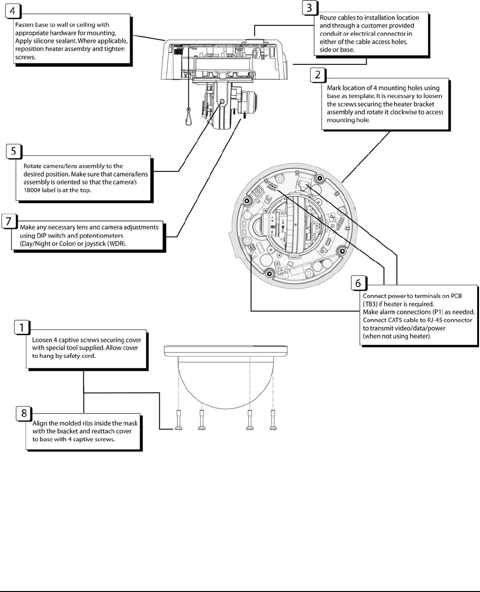
Quick Installation
For complete detailed instructions on how to install the V910, read the Installation section.
Installation Diagram
ii • 3BQuick Installation XX137-67-00 Rev 1208 Roughneck V910 Dome Cameras with PoE

Introduction
The information in this manual covers the installation, operation, and maintenance of the Roughneck™ V910
Series of Impact-Resistant Dome Cameras with PoE. These units should only be installed by a qualified
technician using common hand tools and approved materials and wiring methods in accordance with the
national Electrical Code ANSI/NFPA 70, state and local wiring codes. All interconnecting equipment or
accessories must be UL listed. Any mention in this manual of alarm inputs/outputs have not been evaluated
by UL to be used for burglar alarm functionality. When installing this equipment, use only a UL Listed Class 2
indoor/dry or Class 3 outdoor/wet rated power supply. Read this manual through completely before
attempting installation.
The Roughneck V910 Series of Impact-Resistant Dome Cameras with PoE (Power over Ethernet) offers
high-security cameras in a compact domed housing. They are for indoor/outdoor applications and have
permanent mold construction and a high-impact polycarbonate plastic dome. These camera packages are
designed to handle the toughest environments, including correctional facilities, warehouses and loading
docks. They include “O”-ring sealing and a heater (requires 24 VAC) to allow operation in low temperature
and in all weather conditions. Tamper-resistant screws make the units resistant to vandalism.
The base of the unit screws directly to a wall or ceiling. The camera mounting brackets offer adjustment to
any view required. The camera position is adjustable horizontally and vertically. The V910 series has an
integral high-resolution color camera or day/night camera, including a model with Wide Dynamic Range
(WDR), all with a 3.3-12 mm varifocal autoiris lens. The camera can be powered through the Ethernet
connection (PoE); when using PoE, a PoE device, such as the NETSWITCHPOE-24, is required. For those
installation requiring the heater, both the heater and camera are powered by a 24 VAC input; the camera
includes an isolated power input. The varifocal lens allows for lens adjustment capability and autoiris
adjustment.
The Roughneck V910 IP Camera Dome is a powerful IP video source for a complete digital video
management system based on ViconNet Version 5 software. It is fully compatible with all ViconNet® systems
and is remotely managed and controlled from ViconNet workstations and Kollector™ Elite recorders. It can
deliver up to 30 fps (25 fps PAL) divided across the local camera input at a total nominal bandwidth of
1.7 Mbps at Q5 (360 x 244 pixels).
Equipped with a 10/100 Mbps LAN connection on the PC board, the camera allows direct plug-in to a network
switch. Images received from the IP camera and the other external cameras connected to its external inputs
can be displayed, recorded or archived like any other ViconNet video component using the ViconNet
management software.
The V910 Camera Dome has 4 levels of video resolution; 4 CIF, 2 CIF, CIF and HCIF with 2 levels of
compression; Normal (optimized) MPEG-4 and Full (JPEG). These comprise 8 selectable quality levels.
ViconNet utilizes an MD5 video authentication algorithm which is based on a 128-bit message used to identify
data integrity. Viewing authenticated video can be configured from the software. In addition, the IP camera
dome supports museum search, motion detection, alarm reporting, macros, audio input and alarm
configuration through the ViconNet software interface.
The Roughneck V910 Dome Camera series meets FCC requirements for a Class A device.
XX137-67-00 Rev 1208 Roughneck V910 Dome Cameras with PoE 4BIntroduction • 1

2 • 4BIntroduction XX137-67-00 Rev 1208 Roughneck V910 Dome Cameras with PoE
Table 1
Models, Product Codes and Descriptions
Model Product
Code Description Power (W)
PoE
Power (W)
Nom./Max* Current
Rating (A)
Nom./Max.
V910A-IP5/
V910A-IP5C 9208-75/
9208-76
Indoor/Outdoor; 1/3-in. high-resolution
color camera with 3.3 - 12 mm varifocal
autoiris lens; PoE or 24 VAC capability;
isolated power input; heater; ViconNet
(ver. 4) (LAN) video/data transmission.
NTSC/PAL.
7.5 W 14.5/18.5 0.60/0.64
V910A-DN-IP5/
V910A-DN-IP5C 9209-75/
9209-76
Indoor/Outdoor; 1/3-in. day/night color
camera with 3.3 - 12 mm varifocal autoiris
lens; PoE or 24 VAC capability; isolated
power input; heater; ViconNet (ver. 4)
(LAN) video/data transmission.
NTSC/PAL.
7.5 W 14.5/18.5 0.60/0.64
V910A-WDR-IP5 /
V910A-WDR-IP5C 9210-75/
9210-76
Indoor/Outdoor; 1/3-in. Pixim® high-
resolution day/night color camera with
wide dynamic range (WDR) with 3.3 - 12
mm varifocal autoiris lens; PoE or 24 VAC
capability; isolated power input; heater;
ViconNet (ver. 4) (LAN) video/data
transmission. NTSC/PAL.
7.5 W 14.5/18.5 0.60/0.64
*Note: Nominal power and current levels are calculated @ 24.0 VAC input line voltage. Includes heater.
Maximum power and current levels are calculated @ 29.0 VAC input line voltage. Includes heater.

Installation
Unpacking and Inspection
All Vicon equipment is tested and inspected before leaving the factory. It is the carrier’s responsibility to
deliver the equipment in the same condition as it left the factory.
Inspection for Visible Damage
Immediately inspect the cartons upon delivery. Make a note of any visible damage on all copies of the
carrier’s freight bill.
Make sure the carrier’s agent (the person making the delivery) signs the note on all copies of the bill. If the
agent does not have claim forms, contact the carrier’s office.
Inspection for Concealed Damage
As soon as possible after delivery, unpack the unit and inspect it for concealed damage. Do not discard the
carton or packing materials. If the unit is damaged, contact the carrier immediately and request forms for filing
a damage claim. Make arrangements for a representative of the carrier to inspect the damaged equipment.
If the equipment must be returned for repair, follow the Shipping Instructions at the end of this manual.
Roughneck V910 Dome Components
The Roughneck V910 units consist of a base (which includes the camera mounting bracket with the
camera/lens assembly) and a cover with a smoked dome. Refer to Figure 1.
Base/Camera Mounting Bracket
The base of the unit is constructed of die-cast aluminum. The base is mounted directly to the wall or ceiling.
Two cable access holes are provided. A safety cord is provided to connect the cover to the base. The camera
mounting bracket is attached to the base; the camera is factory-installed. The camera/lens position can be
manually adjusted. A heater is factory-installed inside the base. for units installed in environments that require
it.
Cover/Dome
The cover of the unit is constructed of die-cast aluminum. It has a 4.7 in. (119 mm) diameter dome
constructed of smoked polycarbonate plastic. A mask with a slotted opening is included to help conceal the
camera. The cover is secured to the base with four tamperproof captive screws; a special tool is supplied to
loosen the screws. A safety cord is provided to anchor the cover/dome to the base. Refer to the Maintenance
section of this manual for instructions on the care and handling of the dome.
XX137-67-00 Rev 1208 Roughneck V910 Dome Cameras with PoE 5BInstallation • 3
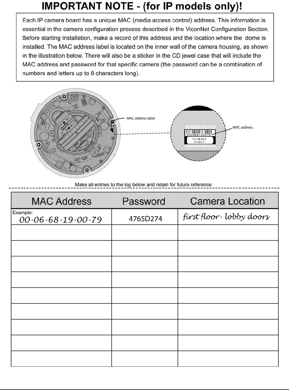
MAC Address
4 • 5BInstallation XX137-67-00 Rev 1208 Roughneck V910 Dome Cameras with PoE
Figure 1
Exploded View
XX137-67-00 Rev 1208 Roughneck V910 Dome Cameras with PoE 5BInstallation • 5
Accessory Kit
There is an accessory kit included with the Roughneck V910. The table below lists the contents.
Description Quantity
Tamperproof driver bit, ¼ hex T-15 (to remove
tamperproof screws) 1
Pipe sealant tape (to seal pipe fitting to housing) 1
Lug (for grounding) 1
Screws (for some appropriate installations) 4
Vent plug (for outdoor installations) 1
Terminal block, 2-pin (24 VAC heater power) 1
Terminal block, 3-pin, for alarm 1
Video focus adjustment cable
(for connection to portable/local monitor) 1
Tool for set screw roll adjustment 1
ViconNet CD 1
Mounting the Unit
Select a location for the installation of the V910 camera. Be sure the area around the selected location is
clear of obstacles (such as steel beams, headers, pipes, electrical wiring, etc.) which would interfere with the
mounting of the camera and that the location can support the weight of the unit [the V910 unit weighs 4 lb
(1.8 kg)]. Video and power cables must be routed to the installation location.
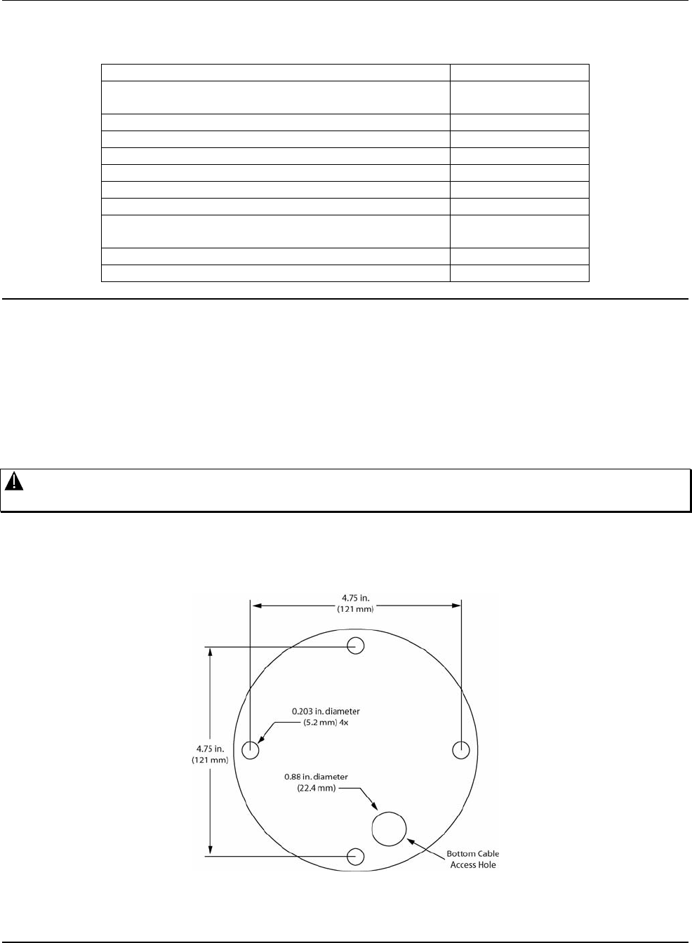
The V910 mounts directly to a ceiling or wall. The base has four mounting holes, and two cable access holes
are provided. As a mounting alternative, the mounting holes align with a standard 4 x 4 electrical box, and the
unit may be mounted to that. Refer to Figure 2. To mount the V910, follow the steps below.
Caution: Do not attach these units to drywall surfaces and do not install mounting screws into the end
grain of wood.
1. Loosen the four captive screws securing the cover to the base with the special tool supplied in the
accessory kit. The cover remains attached to the base by a safety cord. Allow the cover to hang.
2. Using the base as a template, mark the location of the four mounting holes [0.203 in. (5.2 mm) diameter].
See Figure 2.
Figure 2
Mounting Hole Pattern
6 • 5BInstallation XX137-67-00 Rev 1208 Roughneck V910 Dome Cameras with PoE
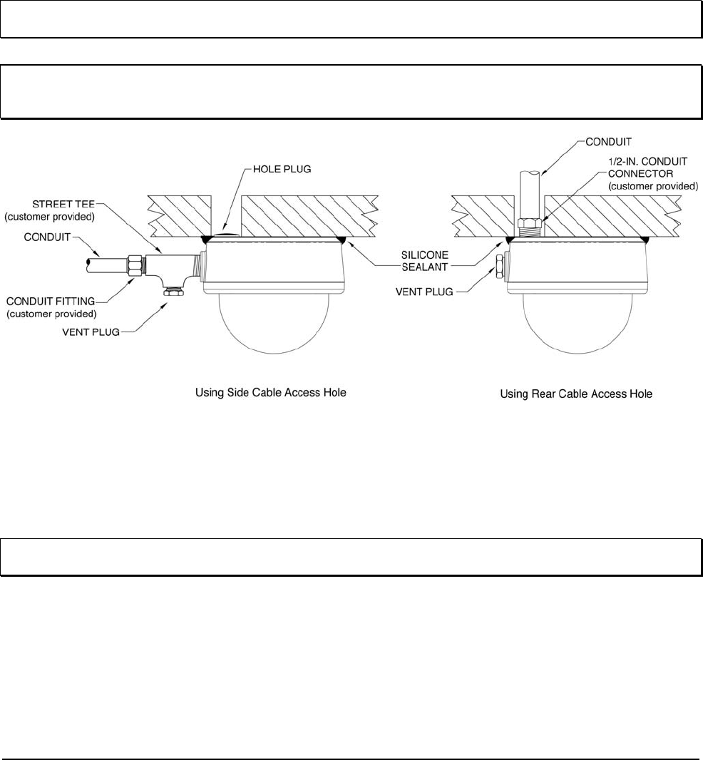
3. There are two (2) cable access holes provided. Drill a hole in the wall or ceiling and route video and
power cables to the selected location and through one of the cable access holes. A 1/2-inch connection
(customer-supplied connector) is provided on the side of the base; the rear port is sized to accept a 1/2-
in. (customer-provided) connector. A conduit or electrical connector (screw-type) can be used in this
threaded hole. See Figures 1 and 2 for hole locations. Apply the provided sealant tape around the
threads of the conduit pipe.
4. If it is desirable to use the rear cable access hole, remove the black hole plug it is shipped with and route
the conduit through the hole. Remove the plug from the side cable access hole and insert the vent plug
provided. If the side cable access hole is used, remove the plug it is shipped with and insert a Street Tee
(customer provided) into the cable access hole. Route the conduit through the top hole and insert the
vent plug provided into the bottom hole. Refer to Figure 3 for installation options.
NOTE: Failure to thoroughly coat threads will result in moisture entering the housing and eventual failure of
the unit.
Note: For outdoor installations, Vicon recommends that the vent plug should only be used if fogging
conditions exist. Additionally, if the side cable access hole is used, the base must be mounted so the
hole is pointed directly downward.
Figure 3
Installation Options
5. Fasten the base to the wall or ceiling with the appropriate hardware for the mounting surface, lag bolts
and sleeve for cement surfaces or machine screws for other surfaces. A nylon washer is provided at each
mounting hole for environmental sealing. If the rear cable access is used, be sure that holes are aligned
correctly so the cable is routed to allow a flush installation of the base. As a mounting alternative, align
the mounting holes with a 4 x 4 electrical box and fasten the base to the box with machine screws.
Note: To assure a watertight seal, apply silicone sealant around the area where the base meets the wall or
ceiling. Vicon recommends Dow Corning® 737 neutral cure sealant or equivalent.
6. The camera/lens assembly can be adjusted to the desired position. Refer to Figure 4. Do not move the
camera/lens assembly by holding onto the lens. For pan adjustment, loosen the two (2) screws on
either side of the camera base bracket; for tilt adjustment, loosen the screw on the camera/lens
assembly. For roll adjustment (turns camera position top/bottom), loosen the two set screws on the
camera/lens assembly and rotate unit to desired position. Be sure to tighten screws after all adjustments.
The varifocal lens can be manually adjusted for focus (near/far) and zoom (telephoto/wide). There is a
potentiometer for adjustment for autoiris on the day/night and color cameras; the WDR camera has
adjustment available from an OSD menu. Detailed instructions follow. When making adjustments, be sure
XX137-67-00 Rev 1208 Roughneck V910 Dome Cameras with PoE 5BInstallation • 7
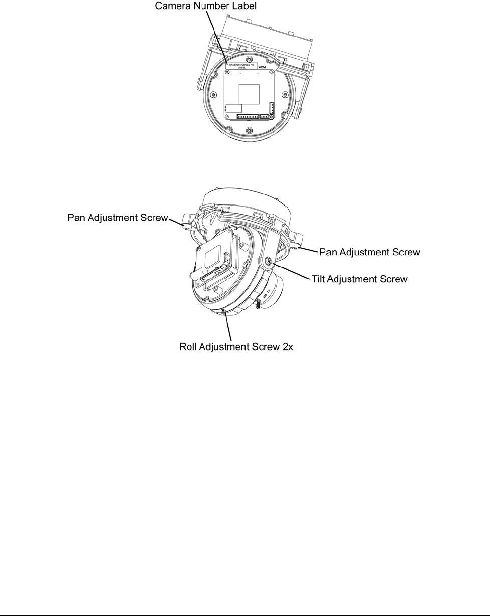
that the lens does not hit the dome. There is a label with the camera “1800” number on the camera/lens
assembly; this marks the TOP of the camera. Make sure the camera/lens is installed so that the label is
on the top for proper video display. Refer to Figure 7.
Figure 4
Camera Position Adjustments
8 • 5BInstallation XX137-67-00 Rev 1208 Roughneck V910 Dome Cameras with PoE
Cable Connections
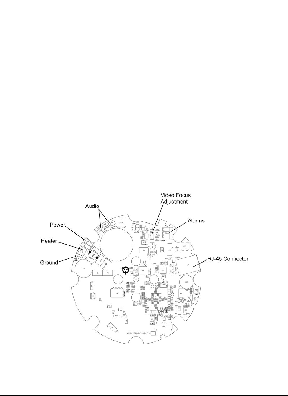
Power, video, alarm, audio and IP connections are made to the printed circuit board (PC board). Refer to
Figure 5 when performing these connections. Refer to the Cable Recommendations in the Reference section.
The V910 PoE models provide support for direct network connection to Kollector Elite Digital Video
Recorders and ViconNet Workstations via ViconNet version 5 software. The PC board allows direct plug-in to
a system network hub, switch or router. Video from the camera is available to all network recorders and
workstations for live view and recording. Video is digitized and made available through the LAN connection.
An RJ-45 connector (J7) is provided on the board for connection to the LAN with a CAT5 cable. This
connection is also used for power (PoE). Refer to Figure 5 and the Table for connections on the ViconNet
board.
Alarm input signals are carried on individually-shielded twisted-pair cable sets. There is a 3-pin alarm
connector (P1) on the PC board. Refer to the Twisted-Pair Cable Recommendations in the Reference
section.
Alarm inputs are driven by a dry contact type switch. These signals are connected to terminal block P1. For
example, a door switch can activate an alarm when connected to an alarm input. As a guideline (under
normal conditions), the cable should be 22 AWG for a 1000 foot (305 m) distance.
Additionally, there are two jacks provided for audio, J3 (MIC) for Audio IN and J6 (SPK) for Audio OUT. At this
time, J6 is not available.
Connector P2 is a video out connection for the video focus adjustment cable to connect to a portable/local
monitor. There is an alternate connector on the camera PC board (day/night and color) or joystick control
(WDR). Refer to Figures 7 and 9, respectively. Either connector can be used. The cable assembly is provided
in the accessory kit for connection.
Figure 5
PC Board Connectors
XX137-67-00 Rev 1208 Roughneck V910 Dome Cameras with PoE 5BInstallation • 9
CONNECTOR/PIN
NUMBER
CONNECTOR TYPE CONNECTOR/PIN LABEL SIGNAL NAME
TERMINAL BLOCK POWER (TB3)
TB3-1 HHot
TB3-2 NNeutral
TERMINAL BLOCK ALARM (P1)
P1-1 ALARM OUT Alarm output
P1-2 GND Ground
P1
-
3
ALARM IN
Al
arm
i
npu
t
RJ-45 LAN (J7)
J7-1 TX + Transmit +
J7-2 TX - Transmit -
J7-3 RX + Receive +
J7-4 POE POWER PoE Power
J7-5 POE POWER PoE Power
J7-6 RX - Receive -
J7-7 POE POWER PoE Power
J7
-
8
POE POWER PoE Power
1/8-IN. PHONO AUDIO
J3 MIC Audio In
J6 SPK Audio Out - N/A
Wiring Connections
Dome Power Connections
Note: Vicon systems and components, like most electronic equipment, require a clean, stable power source.
Voltage irregularities such as surges, drops, and interruptions can affect the operation of your
equipment and, in severe cases, damage certain components.
Power (24 VAC) is connected through a two-position terminal connector on the PC board (TB3). Refer to
Table 2 for the input power connections. This is only for installations requiring heater power.
Note: Use only a UL Listed Class 2 indoor/dry or Class 3 outdoor/wet rated power supply.
1. Locate the power cable terminal on the PC board (removable terminal block).
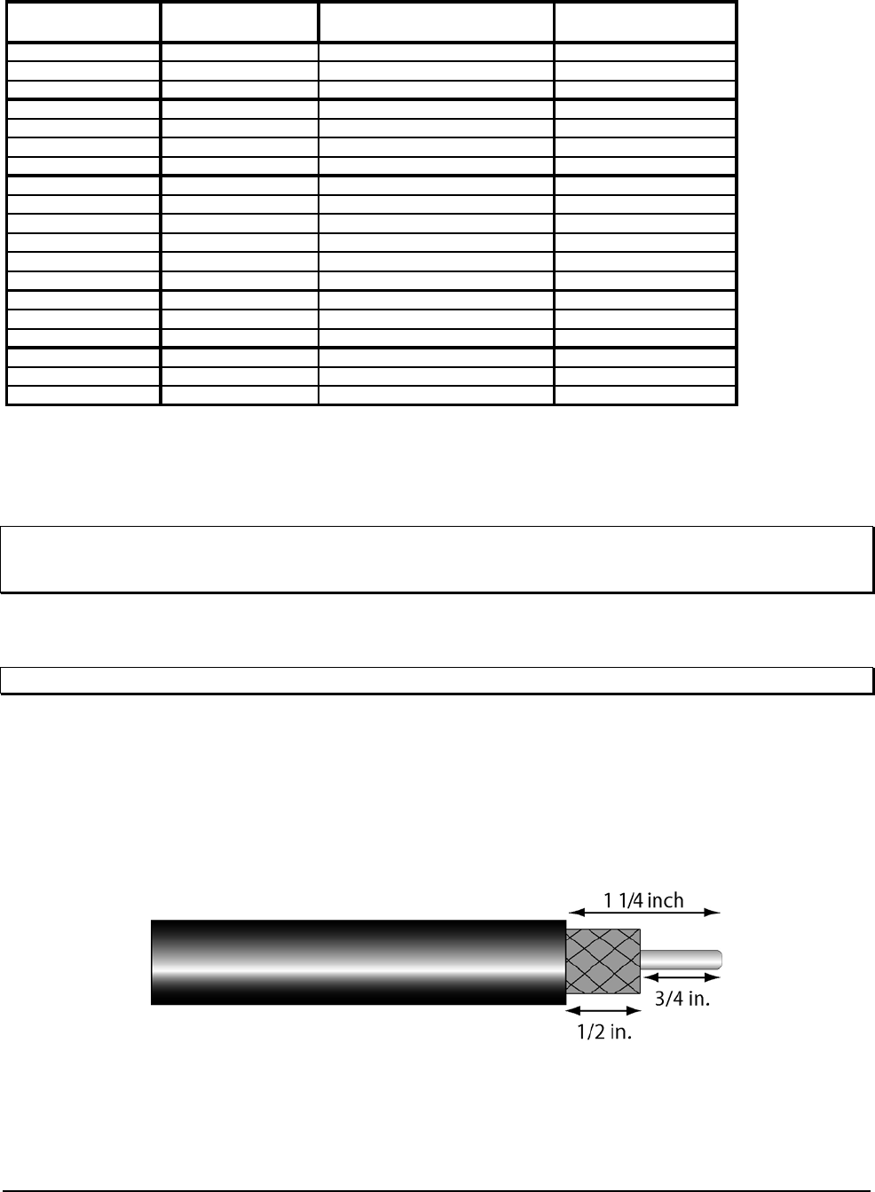
2. Strip approximately 1 in. (25 mm) of insulation off power cables. Then strip off approximately 0.25 in.
(6 mm) of insulation off each individual wire. Refer to Figure 6. Connect the wire into the terminal block.
Repeat for each connection. Refer to Table 2.
3. Connect the terminal block onto the board connector.
The dome accepts 24 VAC for installations requiring the heater, for heater and camera power.
Figure 6
Cable Preparation
10 • 5BInstallation XX137-67-00 Rev 1208 Roughneck V910 Dome Cameras with PoE
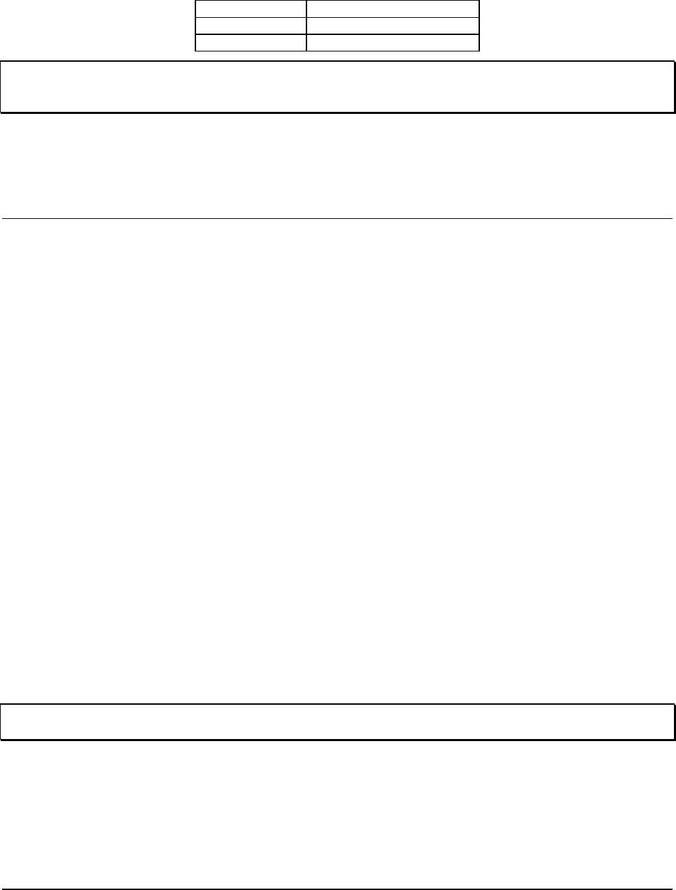
Table 2
Dome Power Connections
Pin Number Function
1 24 VAC
2 24 VAC Return
Note: A grounding tab (P6) is provided on the PC board for those installations requiring a ground. The use of
the ground tab to earth ground is necessary to provide protection to the camera. A Faston (lug) is
provided in the accessory kit.
Heater Connections
The V910 has a heater in the base for those installations requiring it. Refer to Figure 1. The unit is delivered
with the heater connection made to the connector (P8) on the PC board. The heater requires 24 VAC. Refer
to Figure 5.
Camera/Lens Adjustments
After all cabling is complete, the camera and lens can be adjusted. The switch settings that follow refer to the
color and day/night versions. The day/night WDR camera is adjusted using a joystick control. Those
instructions follow. Switch Settings (Color and Day/Night Versions only)
There is a DIP switch on the camera board that allows the selection of: AE/ME (iris setting); ATW/AWB (white
balance setting); AGC (Automatic Gain Control ON or OFF); and BLC (Backlight Compensation ON or OFF).
The default settings on all cameras are: ME, ATW, AGC ON and BLC ON. ME setting is for DC autoiris and
AE setting is for fixed iris (all the cameras in this series have autoiris). Refer to Figures 7 and 8 for the
location and setting of the switches. The DIP Switch is oriented as shown in Figure 8. The ON position is
noted on the camera board. To obtain the sharpest picture possible, the iris adjustment should be made from
a “full bright” setting down to an acceptable video level. This assures that the internal AGC of the camera is
not operational. See Table 3 for camera and lens specifications.
Lens/Autoiris Adjustment
The lens can be manually adjusted for focus and zoom. On the lens, focus [Near∞ (Far)] is the front ring and
the zoom (TelephotoWide) is the back ring. Two video focus adjustment connectors are provided for use
with a portable/local monitor (cable provided in accessory kit) for making adjustment. One is on the PC board
on all the cameras. On the day/night and color cameras, a second connector is on the camera board; for the
WDR camera, a second connector is on the joystick control. Either connector can be used. Refer to Figures
5, 7 and 9. To make these adjustments, loosen the Zoom and Focus lever screws and turn the ring. When
adjustment is complete, retighten the screws. Focusing the lens may be impacted by the smoked lower
dome. After the camera/lens assembly is positioned as required, use the focus ring to adjust the lens to the
sharpest focus. Position the lower dome and check the focus. If it is acceptable, proceed to Final Installation.
If the lens is now out of focus, note the orientation of the dome (position on the 4 screws), as this must remain
constant throughout this procedure. Readjust the focus ring so the image is slightly out of focus and position
the lower dome in the same orientation as before. Repeat this procedure as necessary until the lens is
focused properly with the dome in position. Then proceed to Final Installation.
Note: When adjusting the focus, it is recommended that the iris be completely open (a dark condition, either
at night or using a filter) so that the depth of field does not influence the adjustment.
On autoiris lenses, iris adjustment may be required if the picture appears dark or grainy or has poor color.
There is a potentiometer on the day/night and color camera board to adjust the autoiris (for WDR cameras,
this adjustment is made from the OSD menu). Refer to Figure 7. Turning the potentiometer opens and closes
the iris to regulate light extremes. Turning the potentiometer clockwise opens the iris wider, allowing more
light.
XX137-67-00 Rev 1208 Roughneck V910 Dome Cameras with PoE 5BInstallation • 11
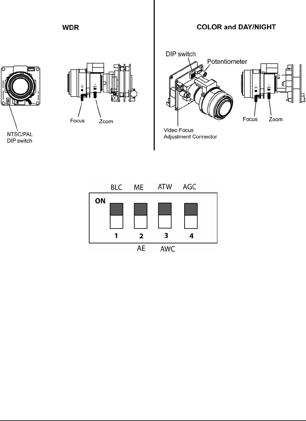
Figure 7
Camera/Lens Adjustments
Figure 8
Default DIP Switch Settings for the Color and Day/Night Cameras Only
12 • 5BInstallation XX137-67-00 Rev 1208 Roughneck V910 Dome Cameras with PoE

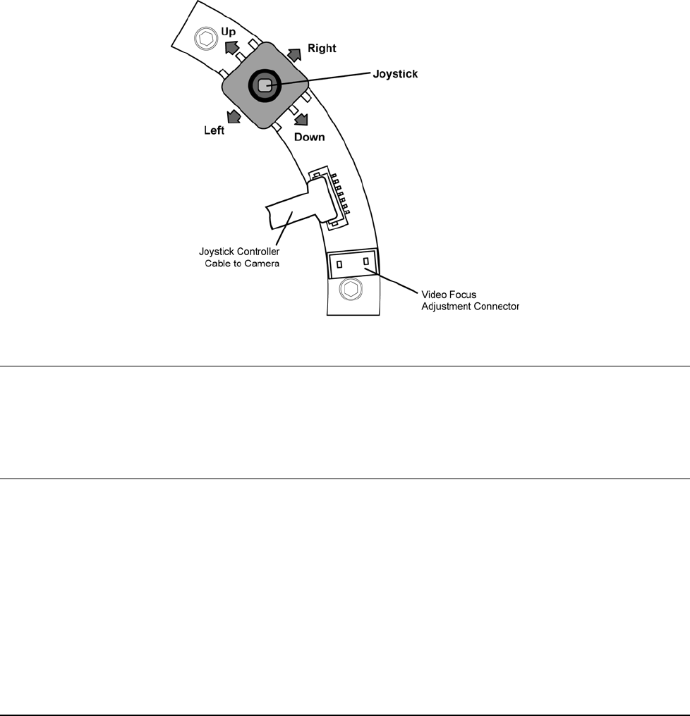
WDR Camera Adjustments
The adjustments for the WDR camera are done via an OSD menu using a joystick on the WDR board. Refer
to Figure 9. The camera must be connected to a portable (local) monitor to use the menu system. Use the
cable included in the accessory kit. Also note that the WDR version has a 2-position DIP switch on the
camera board to set NTSC or PAL. This is factory set. If it is necessary to change this setting, set switch 1 to
ON for NTSC and OFF for PAL. Switch 2 has no function. Refer to Figure 7.
Pressing the joystick down (Center) accesses the menu mode and confirms settings. Moving the joystick up
or down chooses the desired menu selection (UP direction is marked). Moving the joystick to the right or left
chooses the desired menu feature adjustment.
Push the Center key for 3 seconds to access the Main menu. From there, using the joystick, select the
feature to be programmed, Setup ID, Lens, WDR, WB Control, AGC, Low Light, Sync, Day/Night or Exit.
Setup ID
The camera ID can be set to display on the monitor (ON) or not display on the monitor (OFF, default). The
camera ID is a user selectable title for the camera that is up to 12 characters. If display option is ON, the ID
can be set to display on either the top or bottom of the screen in the left, right or center position (default is
up/left).
Lens
Select whether the lens on the camera is manual or autoiris (DC, default). For DC lenses, the DC level can be
adjusted from 20 to -42 to control the brightness of the image (default is -18). (Note: all cameras in this series
have autoiris lenses).
WDR
The Wide Dynamic Range (WDR) level can be adjusted from 20 to -20 (default is -2). The Exposure Level
can be set for from 18 to -18 (default is 0).
WB Control
The White Balance can be controlled by:
ATW (default): The camera automatically controls the white balance in any environment
AWB: One time automatic adjustment for a specific environment. When the environment changes,
this setting must be adjusted. Select AWB and push the joystick to enter menu to adjust the setting
for the particular environment. Hold the joystick to lock this white balance setting.
Manual: User can adjust the colors by increasing or decreasing the WB level from 2500K to 9500 K
(default is 4500K).
AGC
Automatic Gain Control (AGC) can be set ON (default), to activate the feature to adjust the AGC level from 0
to 36 dB (default is 32), or OFF, to deactivate the automatic gain feature, level 43 to -34 (default is 0).
Low Light
The user can control image brightness by adjusting the shutter speed. Select:
Slow Shutter (default): AGC level from 28 to 42 (default is 42), Max Field, for shutter to open X2, X4,
X8, X16, X32 (default X2).
B&W SS: Black-and-white slow shutter.
Gain: Makes the picture brighter.
Sync
User can select Internal (default) for internal synchronization or Line Lock for phase adjustment (from 0 to
620) to prevent picture roll when switching between cameras in multiple camera installations. The Line Lock
feature is not available on this series of cameras.
XX137-67-00 Rev 1208 Roughneck V910 Dome Cameras with PoE 5BInstallation • 13
Day/Night
The user can select how the day/night function is set for changing from color to black-and-white:
AUTO (default): Color BW Level 20 to 35 (default is 32); BW Color level 0 to 10 (default is 5).
Color
BW
Exit Menu
When selecting Exit, the user can:
EXIT NO CHANGES: Exits the menu system without making any changes
SAVE NEW AND EXIT: Save all changes made before exiting the menu system
RESTORE FACTORY SETTINGS: Revert all settings back to factory defaults
SW REV: Version information
Figure 9
WDR Board Adjustments
Final Installation
After all cable connections are made, test the camera/lens to see if any further adjustments are necessary.
Align the viewing slot in the mask with the camera/lens assembly. Reattach the cover to the base by aligning
the four captive screws with the holes in the base. Any alignment of holes and screws is acceptable. The
cover can be rotated 90° by aligning the screws/holes differently.
Configuring ViconNet
The following information is provided for installing ViconNet for the V910 IP dome. The V910 IP camera dome
is shipped with one CD that contains the ViconNet version 5 software needed to setup your IP system,
including the application setup, the camera firmware and setup software (VNSetup). Be sure the ViconNet
Workstation meets the minimum requirements, is running the ViconNet application (version 5) (VNSetup) and
has the proper PTZ camera driver. The VNSetup is found on the included CD under software, IP Camera
Setup. Refer to appropriate ViconNet documentation.
14 • 5BInstallation XX137-67-00 Rev 1208 Roughneck V910 Dome Cameras with PoE
Network Considerations
The V910 Camera Dome can be connected to any ViconNet network (Version 5 software). Kollector Elite
Recorders and ViconNet Workstations can be used for live viewing and recording of network-streamed video.
A network can be as simple as a single V910 connected to a ViconNet Workstation or can be complex with
the addition of several networks interconnected via WAN.
When adding a V910 IP Camera to the ViconNet network, the following items must be considered:
• The number of cameras on a switch with respect to switch capabilities and system bandwidth mapping.
• Bandwidth limitations on ports connected to workstations (using 100 or 1000 Mbps).
• Workstation capabilities such as processing speed, disk write speed and display card strength.
• Storage size and location types including local Workstation recording, attached SCSI RAID and
integrated NAS/SAN devices.
The default parameters on the IP dome are:
Factory Defaults Network Defaults
IP address: [10.10.10.1] IP address: [1.1.1.2]
Nucleus IP address: [1.1.1.1] Nucleus IP address: [1.1.1.1]
Net Mask address: [255.255.255.0] Net Mask address: [255.255.255.0]
Gateway address: [0.0.0.0] Gateway address: [1.1.1.1]
On first startup, the camera will attempt to establish connection to the Nucleus with the default address
(1.1.1.1). Connecting it to an active Nucleus is done through the VNSetup utility.
Note: When connecting to ViconNet application version 5, the number of concurrent users viewing video
from the same device cannot exceed 10 users.
Groups and Users Restrictions
ViconNet allows creating Multiple Groups and Users in order to limit the rights to different levels. For more
information on how to create Users and Groups, refer to the latest revision of ViconNet manual XX113.
Although the ViconNet software does not limit the number of Groups and Users that can be created, the
Roughneck V910 Camera Dome has Users and Groups limitations. For ViconNet version 5, the dome can
support the first 20 Groups (including Administrators and Guests) and the first 100 Users.
Configuring the Network Settings
Note: Before starting, make sure that VNSetup is installed on the configuring PC\workstation. Installation is
done using the CD included.
There are two ways to change the IP dome network settings:
• Activating the camera for the first time: via VNSetup application.
• Connecting the camera to an active Nucleus: via ViconNet application (connection to same Nucleus as
the camera is necessary).
Note: In order to install firmware, the PC and camera must be on the same IP network.
Using the VNSetup Utility
VNSetup consists of several TABs. Each TAB provides different functionalities.
Note: Once the IP Camera Setup is run the first time, a shortcut is placed on the desktop for future use.
1. Make sure the MAC address and password of the camera is available. Use MAC Address log provided.
2. Verify that the camera is physically connected to the configuring workstation via the network.
XX137-67-00 Rev 1208 Roughneck V910 Dome Cameras with PoE 5BInstallation • 15
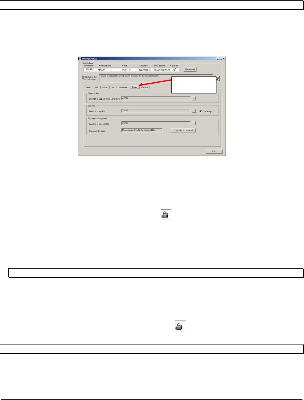
Setup TAB
Note: Since the Setup configuration affects the entire installation process, it MUST be configured first.
In the Setup TAB, 3 fields are defined. The Upgrade files field indicates the installation upgrade directory. The
Log files field allows the user the ability to put a copy of log files in a predefined directory. Password
management selects a directory to save all password files. (By default, the setup files will be installed to
C:\VUG.) In Password file status, the number of passwords stored is displayed. Load a list of passwords is
intended for very large sites only. Contact Technical Support to use this feature.
Setup
Select TAB
The Select TAB allows the user to select the relevant IP Unit in order to change its settings or to upgrade its
version.
1. From the Unit selection list, select the relevant IP product. In case of multiple sites, it is advised to use
the filter under the Unit Type field. Click on any column tab to sort names by that definition in ascending
or descending order.
2. Once the desired unit has been selected, notice the icon, indicating a password protected unit. In
order to change the selected unit’s settings on the local PC that is running the VNSetup, a unique
password must be entered. The screen will display how many units there are and how many of those
are password protected (locked). A remote unit, as in systems using network routers and VLANS
(virtual LANs), will not display in the Unit selection list. If you want to select a remote unit, manually
enter the IP address in the IP address of remote unit field and click Find remote unit. The remote unit is
added to the list.
Note: This is correct for BIOS from version 1.0.10.86 and later (ViconNet version 3 and higher).
3. Password authentication
There are two authentication options. You can either authenticate a specific unit, by entering its
password, or use a Nucleus authentication, allowing you access to all units in the network.
3.1. Unit authentication - On the Unit password field, enter the unit password and press the Add
password button. Once approved, notice that the icon has disappeared and the user may
proceed to next phase. The password will be saved on this unit.
Note: The unit password is supplied on the sticker with the MAC address in the camera package.
16 • 5BInstallation XX137-67-00 Rev 1208 Roughneck V910 Dome Cameras with PoE
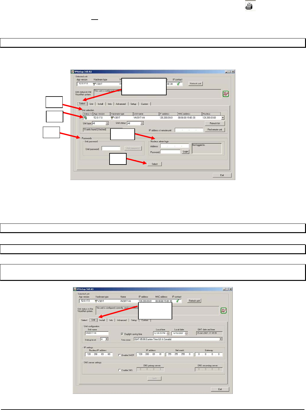
3.2. Nucleus authentication - On the Nucleus admin login field, enter a valid Nucleus IP address
and password and press the Login button. Once approved, notice that the icon has
disappeared from all the units currently connected to the selected Nucleus and the user may
proceed to next phase.
4. Press the Select button on the lower section of the screen.
Note: You MUST click the Select button to add the unit to the list; verify that it is added to the list.
5. The selected unit appears on the Selected unit section on the top of the screen and settings can be
changed.
1
Select
2
3 3.2
4
Unit TAB
The Unit TAB allows the user to change the following settings: Unit name, Nucleus IP address, IP address,
Net mask, Gateway, DNS, DHCP, Time Zone, daylight saving time, Local time, Local date, and Debug level,
on a scale of 0-4, where 4 is most information.
Note: The Apply button must be pressed for changes to take effect.
Note: Verify all IP addressing parameters with your IT administrator.
Note: In order for the DHCP option to work properly, verify that the server does not expire the IP address
licensed to the camera. (Camera should always receive the same IP address from the DHCP server.)
Unit
XX137-67-00 Rev 1208 Roughneck V910 Dome Cameras with PoE 5BInstallation • 17
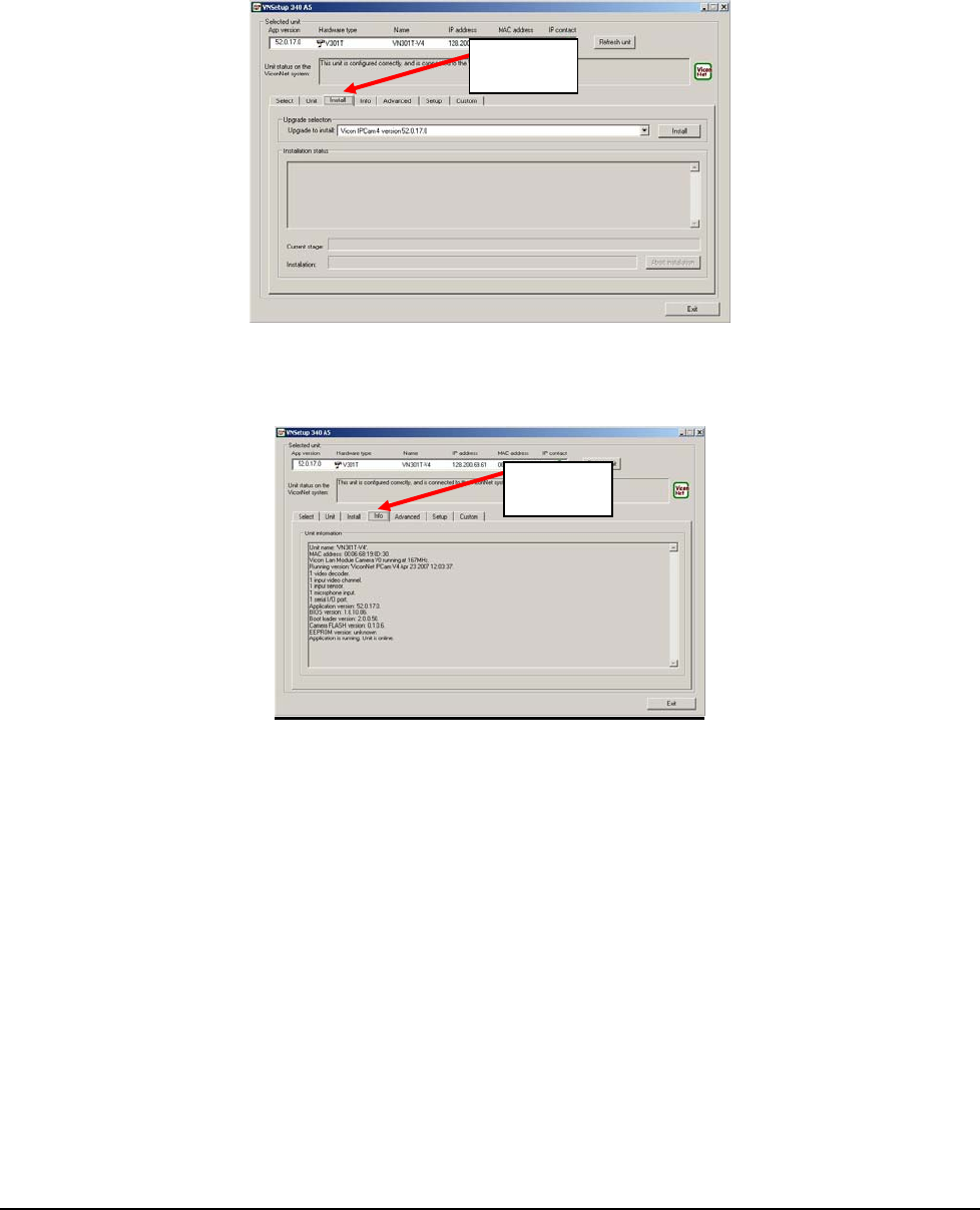
Install TAB
The Install TAB allows the user to install/upgrade newer versions. Choose the correct version and click Install
to send to the selected unit.
Install
Info Tab
The Info TAB displays the selected IP product general information/
Info
18 • 5BInstallation XX137-67-00 Rev 1208 Roughneck V910 Dome Cameras with PoE
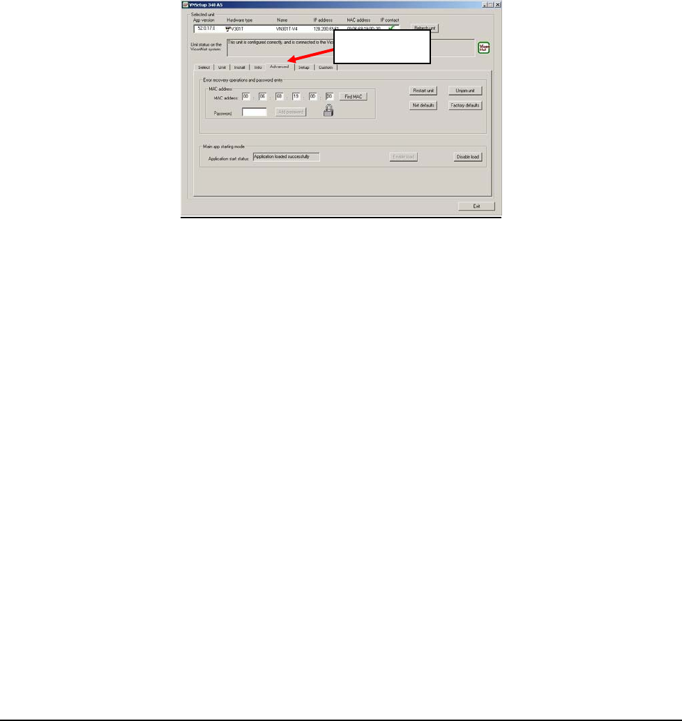
Advanced TAB
The Advanced TAB functionalities allow the user to handle unexpected events on a specific remote unit when
they occur.
When a problem occurs, the user can choose to Unjam unit to restart the unit’s firmware, Restart unit to
restart the hardware, Net defaults to return the initial network settings and Factory defaults to return to the
initial configuration.
The Main app starting mode, Application start status may be Unknown, Application loaded successfully or
Loading of application is disabled. The Disable load button allows the pausing of the application load in case
of software issues while still permitting communication via VNSetup; the Enable load button resumes the
application load.
Advanced
XX137-67-00 Rev 1208 Roughneck V910 Dome Cameras with PoE 5BInstallation • 19
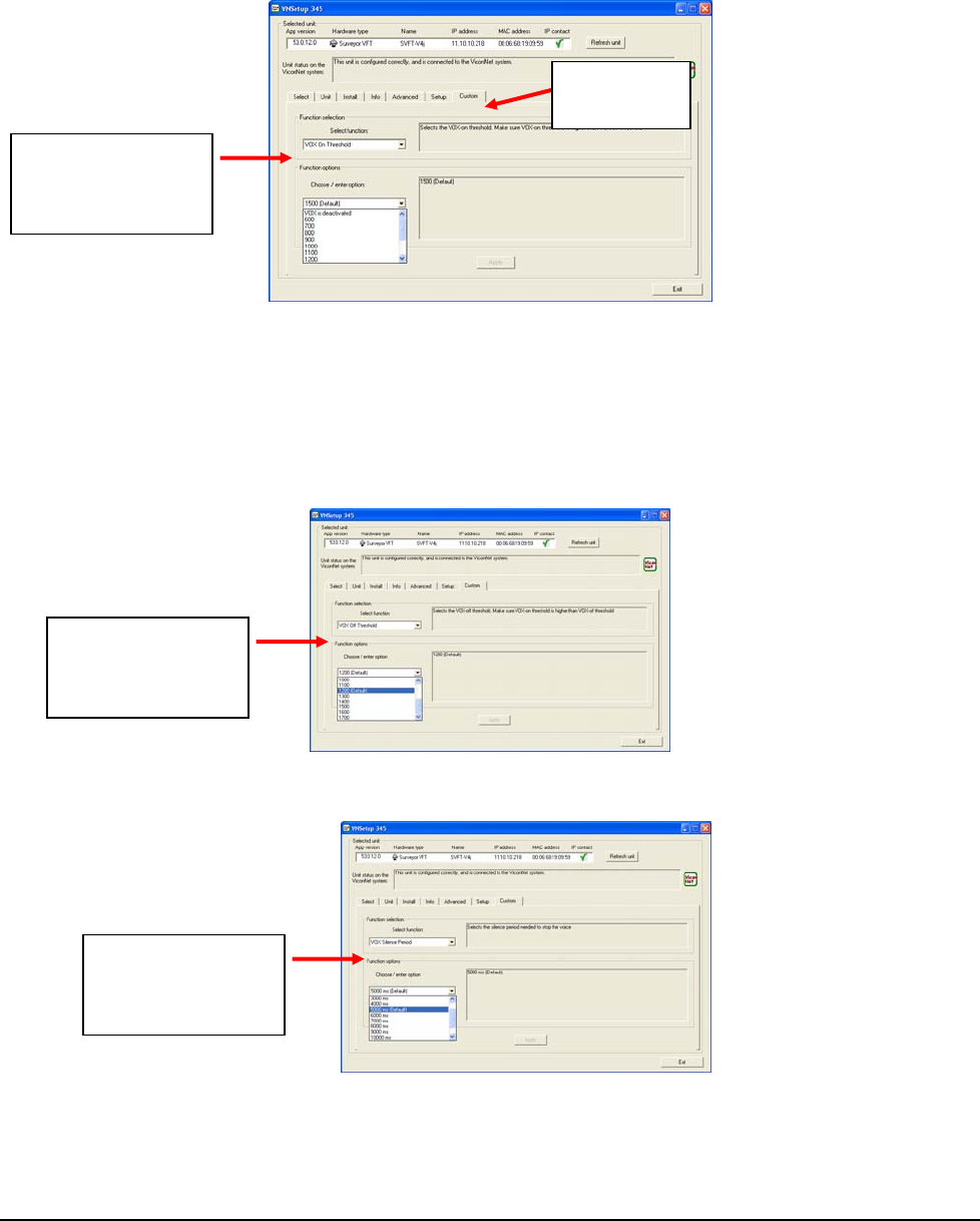
Custom TAB
The Custom TAB allows setup of the VOX settings. The VOX mechanism allows setting the IP device so that
it will not transmit audio if the level it too low (i.e., an empty room). This conserves storage and allows
recording only true sound, not background noise or silence.
Custom
Function list:
VOX On
Threshold
The VOX menu has three function options that are selected from the drop down function list:
VOX On Threshold – Defines the audio level at which the input turns ON. At this level, audio is
captured and sent from the device. Default setting is 1500. This setting also allows the VOX mechanism to be
deactivated, having audio ON all the time.
VOX Off Threshold – Defines the audio level at which the input shuts OFF. Default setting is 1200.
Function list:
VOX Off
Threshold
VOX Silence Period – Defines the time between reaching VOX OFF level and the actual audio turns
off. Default setting is 5000 ms.
Function list:
VOX Silence
Period
20 • 5BInstallation XX137-67-00 Rev 1208 Roughneck V910 Dome Cameras with PoE
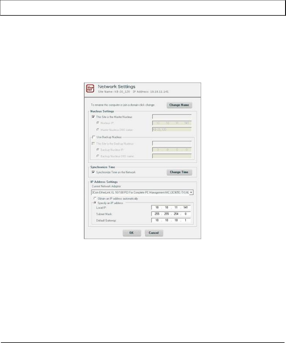
ViconNet Configuration
After the camera dome has been setup with the proper IP address, configuration features from a remote
workstation, server or recorder are available as follows.
• A network settings screen is used to modify the camera dome’s IP parameters. This allows great
flexibility in network setup.
Note: This setup can be performed from any VN-WS/VN-NVR workstation connected to the IP dome and to
the Nucleus or from a Kollector Elite.
1. Verify that the camera is connected to the network, that it is active and that it is configured to use the
same Nucleus.
2. From the workstation desktop, run the ViconNet application.
3. After logging in, open the site setup selection window.
4. Select the IP dome camera setup.
5. Open the Network Setup and Site Name setup window. Network Settings window will display.
See Figure below.
6. Change the required parameters and click OK. (See your IT administrator for specific network
parameters.) Application of the camera will restart.
Network Settings Window
• An Authorization screen is used to establish authority levels, by user group. Functions such as PTZ
and video view, record and playback can be set for authority level.
• A priority screen is used to establish video quality and FPS levels.
XX137-67-00 Rev 1208 Roughneck V910 Dome Cameras with PoE 5BInstallation • 21

22 • 5BInstallation XX137-67-00 Rev 1208 Roughneck V910 Dome Cameras with PoE
ViconNet (IP/LAN) Version Operation
The following functions are supported by the ViconNet system through a workstation, recorder or server.
1. System macros can be configured to view and record the dome’s video. In addition, within macros,
alarms can be sent and remote macros triggered.
2. An alarm can be triggered upon video motion detection and video loss. This alarm can be sent remotely
to other networked units.
3. PTZ control can be performed from any networked workstation, recorder or server. Authorization for PTZ
can be assigned to specific operator levels.
Refer to the most recent version of the ViconNet workstation manual XX113 for complete information
on operation. A copy of the manual can be found on the CD included.
Operation
When power is applied to the camera, the Roughneck V910 views the selected scene.
Maintenance
The Roughneck V910 Impact-Resistant Cameras require no scheduled maintenance except for the
occasional cleaning of the lower dome.
Care and Cleaning of Lower Dome
The inside surface of the smoked (gray-tinted) dome is easily scratched. Take the following precautions to
maintain the dome’s surface.
1. Always handle the dome by the flange and avoid touching the inside surface.
2. If dust or other contaminants accumulate in the dome’s interior, they should be removed with clean dry air
pressure (compressed air cans).
3. If spots, streaks or stains appear on the interior or exterior, they can be removed with a solution of 50%
isopropyl alcohol and 50% water using a microwave-safe (aluminum free) paper towel. Dry with clean, dry
pressurized air.
4. Scratches or surface blemishes on the exterior or interior may be removed with a nonabrasive wax using
a soft cleaning cloth. Either liquid or spray cleaner/wax suitable for fine furniture is acceptable.
Caution: Excessive pressure or rubbing on the dome’s surface can cause permanent scratches that may
render the dome unusable.
5. Clean all surfaces with any soft cleaning cloth and a solution of Ivory soap as a cleaning agent.
Caution: For warranty protection, implement this instruction exactly as stated.
XX137-67-00 Rev 1208 Roughneck V910 Dome Cameras with PoE 6BOperation • 23

Shipping Instructions
Use the following procedure when returning a unit to the factory:
1. Call or write Vicon for a Return Authorization (R.A.) at one of the locations listed below. Record the name
of the Vicon employee who issued the R.A.
Vicon Industries Inc.
89 Arkay Drive
Hauppauge, NY 11788
Phone: 631-952-CCTV (2288); Toll-Free: 1-800-645-9116; Fax: 631-951-CCTV (2288)
For service or returns from countries in Europe, contact:
Vicon Industries Ltd
Brunel Way
Fareham, PO15 5TX
United Kingdom
Phone: +44 (0) 1489 566300; Fax: +44 (0) 1489 566322
2. Attach a sheet of paper to the unit with the following information:
a. Name and address of the company returning the unit
b. Name of the Vicon employee who issued the R.A.
c. R. A. number
d. Brief description of the installation
e. Complete description of the problem and circumstances under which it occurs
f. Unit’s original date of purchase, if still under warranty
3. Pack the unit carefully. Use the original shipping carton or its equivalent for maximum protection.
4. Mark the R.A. number on the outside of the carton on the shipping label.
24 • 8BShipping Instructions XX137-67-00 Rev 1208 Roughneck V910 Dome Cameras with PoE
Reference
Coaxial Cable Recommendations
Caution: Careful selection of proper cable is essential to obtain the best performance from this equipment. Vicon assumes no
responsibility for poor performance when cables other than those recommended, or equivalent, are installed. In all cases, coaxial cable
impedance should be 75 ohms.
Materials
Use only a pure copper center conductor. Do not use a copper-plated steel or aluminum center conductor, as they will
result in poor quality video. Solid-core bare copper conductor is the best type, where flexing and bending will be minimal. If
severe bending and flexing is required for installation, use a stranded center conductor. Never exceed the manufacturer’s
minimum bend radius specification. Use cellular (foam) polyethylene dielectric except where heavy moisture exists. For
moisture conditions, use solid polyethylene dielectric cable with a heavy exterior insulation. The shield must be copper
braid providing 95% or better coverage.
Cable Types
The cable types listed below are the most common 75-ohm types used. They vary in size (diameter), dielectric type and
net DC resistance. The larger cable results in a lower DC resistance and better video quality, with increased difficulty in
handling and installation. Let the required picture quality and cable distance provide a guide in choosing the best cable
type. For cables other than the approved Vicon types below, contact the manufacturers listed below. Note that “BC” refers
to bare copper and “TC” refers to tinned copper.
Recommended Coaxial Cable Types
Cable
Type Belden
Type No. Alpha
Type No. West Penn
Type No. Type Center
Conductor Type Shield and
% Coverage DC Resistance
ohms/1000 ft (km)
RG-11/U 8213 9847 811,4811 14 Solid BC BC braid (95%) 2.6 (8.5)
RG-6/U 9248 9804C 806,4806 18 Solid BC Foil + 61% TC braid (100%) 7.5 (24.6)
RG-59/U 8281* ---- 815 20 Solid BC 2 TC braids (96%) 9.9 (32.5)
RG-59/U 9259 9803 816 22 Stranded BC BC braid (95%) 15.0 (49)
RG-59/U 9659 ---- ---- 22 Stranded BC BC braid (95%) 15.0 (49)
*Requires special BNC-M connector due to 0.305 nominal O.D.
Belden Inc. http://www.belden.com/ (800) 235-3361
Alpha Wire Company http://www.alphawire.com/ (800)-52 ALPHA (522-5742)
West Penn Wire http://www.westpenn-cdt.com/ (800)-245-4964
Picture Quality vs. Cable Length
Maximum Cable Run** ft (m)
Picture Quality RG-59/U RG-6/U RG-11/U
Usable picture 1100 (350) 1500 (450) 2400 (750)
Clean picture 820 (250) 1000 (300) 1600 (500)
Best picture 400 (120) 530 (160) 820 (250)
** For longer cable runs, use a Vicon Video Amplifier to obtain a suitable picture.
XX137-67-00 Rev 1208 Roughneck V910 Dome Cameras with PoE 9BReference • 25
26 • 9BReference XX137-67-00 Rev 1208 Roughneck V910 Dome Cameras with PoE
Network Cable
Caution: Careful selection of proper cable is essential to obtain the best performance. Vicon assumes no responsibility for poor
performance when cables other than the recommended types, or equivalent, are used.
Materials
Use pure copper stranded conductors to obtain a low DC resistance. The preferred insulation and cable jacket is Polyvinyl
chloride (PVC). It has better electrical characteristics than Polyethylene and resists flames, sunlight and most solvents, but
is more vulnerable to moisture.
Cable Types
The most commonly used cable types are CAT5, CAT5e and CAT6. These category cables are best suited for Ethernet
network applications.
Choose a Belden cable type by referring to the characteristics listed below. The Table below should be used as a
guideline when cables other than Belden are used. Materials and construction must follow the guidelines above.
CABLE TYPE WIRE SIZE
(AWG) INSULATION
MATERIAL JACKET
MATERIAL CATEGORY BANDWIDTH
(MHz) MAXIMUM
DISTANCE
(ft/m)
NUMBER OF
TWISTED
PAIRS
Belden 1624P 24
Fluorinated
Ethylene
Propylene
Low Smoke
PVC 5 100 246/75 4
Belden 1583A 24 Polyolefin PVC 5e 100 328/100 4
Belden 1585A 24
Fluorinated
Ethylene
Propylene PVC 5e 100 328/100 4
Belden Inc. http://www.belden.com/ (800) 235-3361
Table
Recommended Network Cable Types
Twisted-Pair Cable
Caution: Careful selection of proper cable is essential to obtain the best performance. Vicon assumes no responsibility for poor
performance when cables other than the recommended types, or equivalent, are used.
Materials
Use a pure copper stranded conductor with or without a tin-plating to obtain a low DC resistance. Do not use cable with
either steel or aluminum stranded conductor because they do not transfer signals effectively for long distances. The
preferred insulation and cable jacket is Polyvinyl chloride (PVC). It has better electrical characteristics than polyethylene
and resists flames, sunlight and most solvents, but is more vulnerable to moisture.
Cable Types
The most commonly used cable types are dual individually-shielded, twisted pair in a single jacket. This configuration is
the most convenient for RS-422/ RS485 applications. Single individually-shielded, twisted pair is also a suitable cable.
Choose a Belden cable type by referring to the characteristics and maximum distances listed below. The maximum
distance for the most reliable digital control refers to the distance between the CPU/Keypad and the Camera Dome
Assembly. The characteristics of the cables in Table 6 should be used as a guideline when cables other than Belden are
used. Materials and construction must follow the guidelines above.
¹Datalene is a Registered Trademark of Belden.
CABLE
TYPE WIRE SIZE
(AWG) INSULATION
MATERIAL JACKET
MATERIAL DISTANCE ft (m)
max. NUMBER OF
TWISTED PAIRS
Belden 9406 22 PVC PVC 5000 (1500) 2
Belden 9402 20 PVC PVC 5000 (1500) 2
Belden 8723 22 Polypropylene PVC 8000 (2400) 2
Belden 8162 24 Datalene¹ PVC 15000 (4600) 2
Belden 9729 24 Datalene¹ PVC 15000 (4600) 2
Belden 9182 22 Datalene¹ PVC 25000 (7600) 1
Belden Inc. http://www.belden.com/ (800) 235-3361
Recommended Individually-Shielded, Twisted-Pair Cable Types
XX137-67-00 Rev 1208 Roughneck V910 Dome Cameras with PoE 9BReference • 27
Technical Information
ELECTRICAL
Input Voltage: PoE or 24 VAC ±20% (when heater power is required), isolated input.
Use only a UL Listed Class 2 indoor/dry or Class 3 outdoor/wet rated
power supply.
Power Consumption: PoE: 7.5 W.
14.5 W nominal; 18.5 W max., including heater*.
Current Rating: 0.60 A nominal; 0.64 A max., including heater*.
Maximum Operating
Distance
(Nominal, including Heater):
Voltage Wire Gauge ft (m)
20 18 16 14 12
24 VAC 321
(98) 512
(156) 815
(248) 1292
(394) 2058
(627)
Heat Equivalent: 0.8 btu/min (0.2 kg-cal/min) nominal;
1.05 btu/min (0.27 kg-cal/min) max., including heater.
Note: These figures represent the conversion of 100% of the electrical
energy to heat. Actual percentage of heat generated will be less and will vary
from product to product. These figures are provided as an aid in determining
the extent of cooling required for an installation.
Connectors: Power (heater): 2-pin connector.
Heater: 2-pin connector (factory installed).
Video/Data/Power (PoE): RJ-45.
Alarms: 3-pin screw terminal.
Audio: 1/8-in. phono jacks.
Video Output
Impedance: 75 ohms.
Scanning System: EIA/NTSC: 525 lines, 60 fields/sec.
CCIR/PAL: 625 lines, 50 fields/sec.
Radio Frequency
Emission Rating: FCC Class A.
Camera/Lens
Specifications: Refer to Table 3.
Day/Night Camera Operation: In Night mode with the IR filter removed,
the CCD can respond to IR light sources at 720 – 850 nm.
*Note: Nominal power and current levels are calculated @ 24.0 VAC input line voltage.
Maximum power and current levels are calculated @ 29.0 VAC input line voltage.
28 • 10BTechnical Information XX137-67-00 Rev 1208 Roughneck V910 Dome Cameras with PoE

VICONNET (IP)
Communication Software: ViconNet Digital Management System.
LAN Interface: 100 Mbps, TCP/IP Unicast.
Number of Video Channels: 1, over LAN connection.
Video Formats Supported: NTSC and PAL, model dependant.
Video Transmission Rate: 1 channel @30 frames per second (25 fps, PAL) maximum.
Number of Simultaneous
Video Streams: Maximum of 10 viewing/recording streams per camera.
Video Transmission
Resolution: 480 horizontal TV lines maximum at 720 x 488 pixel pallet (864 x 586, PAL).
Video Quality: ViconNet software quality 1-8, selectable on a 4-position bar with
2 compression level settings in resolutions 720 x 488 (864 x 586 PAL),
720 x 244 (864 x 293, PAL), 360 x 244 (432 x 293, PAL), 360 x 122
(432 x 146, PAL).
Audio: 1 line-level microphone input; 0 dbm output, 32 KHz bandwidth,
600 ohm impedance and 2 V RMS (1 V p-p) output dynamic type.
Alarm: 4 in, NO/NC (through V910 inputs).
Video Bandwidth: 1.7 Mbps (per video stream), nom.
SOFTWARE OPERATION (ViconNet)
Network Setup: Standard network protocol type using IP addressing scheme and separate
PC application software.
Site Authorization: Camera can be setup using remote recorder or workstation GUI.
Permissions can be assigned for macro create & edit, alarm setup,
Authentication, Reports and System Status. Supports up to 20 Groups and
100 Users.
Macro Create & Edit: System macros can be configured to use the camera’s video. In addition,
within macros, alarms can be sent and remote macros run.
Alarm Setup: An alarm can be triggered on video motion detection and loss. The alarm can
be sent to remote units.
Authentication: The video from the camera can be set to view the Authentication status
symbol (A) on the displayed video.
Picture Quality and
FPS Priority: Camera video can be setup to prioritize recorded picture quality and video
FPS. Priority can be assigned to user/macro recording for highest requested
video quality or Master user control.
XX137-67-00 Rev 1208 Roughneck V910 Dome Cameras with PoE 10BTechnical Information • 29

30 • 10BTechnical Information XX137-67-00 Rev 1208 Roughneck V910 Dome Cameras with PoE
OPERATIONAL
Tilt and Horizontal
Adjustment: 3 axis adjustment, pan, tilt and roll.
MECHANICAL
Application: Indoor/outdoor.
Mounting: Ceiling or wall. Accessories available for pendant or in-ceiling installations.
Dimensions: Height: 5.1 in. (130 mm).
Total Diameter: 6.1 in. (155 mm).
Dome Diameter: 4.7 in. (119 mm).
Weight: Approximately 4 lb (1.8 kg).
Construction: Base/Cover: die-cast aluminum.
Dome: injection-molded polycarbonate plastic.
Finish: Base/Cover: painted light beige.
Dome: smoked.
ENVIRONMENTAL
Housing: Evaluated to UL standard 50 with an environmental rating of 4X.
Operating Temperature
Range: -22 to 140° F (-30 to 60° C).
Operating Humidity: Up to 95% relative, noncondensing.
Storage Temperature
Range: -40 to 150° F (-40 to 65° C).
Storage Humidity: Up to 90% relative, noncondensing.
Wind Load: Heavy rain or snow driven by winds up to 80 mph.
(Not evaluated by UL)
Table 3
Camera Specifications
Model Image
Device Color/
Mono Resolution Sensitivity
Camera
Features Electronic Iris
Signal-to-
Noise Ratio
(TV lines) fc (lux) (sec)
V910A-IP4/
V910A-IP4C
1/3” CCD,
2:1 interlace,
NTSC/PAL
Color
550
0.03 (0.3)
at 30 IRE,
f/1.2
AGC, BLC,
ATW/AWB,
AE/ME
DIP switch
selectable
NTSC: 1/60–1/100,000
PAL: 1/50 – 1/100,000
>48 dB
(AGC off)
V910A-DN-IP4 /
V910A-DN-IP4C
1/3” CCD,
2:1 interlace,
NTSC/PAL
Color/
Day/Night
Color: 550
Mono: 580
Color: 0.03
(0.3)
B&W: 0.004
(0.04)
at 30 IRE,
f/1.2
AGC, BLC,
ATW/AWB,
AE/ME
DIP switch
selectable
NTSC: 1/60–1/100,000
PAL: 1/50 – 1/100,000
>48 dB
(AGC off)
V910A-WDR-IP4 /
V910A-WDR-IP4C
1/3” CMOS,
progressive,
NTSC/PAL
Color
Day/Night
WDR
540
0.008 (0.08)
at 30 IRE,
f/1.2
(DSS ON)
AGC, WDR,
ATW/AWB,
AE/ME, Low
Light, Day/Night
OSD selection
NTSC: 1/60–1/100,000
PAL: 1/50 – 1/100,000
>48 dB
Lens Specifications
Model Focal Length Field-of-View
(mm) Horizontal Vertical
V910A--IP4/C
V910A-DN-IP4/C
V910A-WDR-IP4/C 3.3 - 12 varifocal with autoiris 83.9° -.23.91° 61.9°- 17.93°
XX137-67-00 Rev 1208 Roughneck V910 Dome Cameras with PoE 10BTechnical Information • 31

Vicon Standard Equipment Warranty
Vicon Industries Inc. (the “Company”) warrants your equipment to be free from defects in material and workmanship under
Normal Use from the date of original retail purchase for a period of three years, with the following exceptions:
1. VCRs, all models: Labor and video heads warranted for 120 days from date of original retail purchase. All other
parts warranted for one year from date of original retail purchase.
2. Video monitor CRT (cathode ray tube) and LCD monitors, all models: One year from date of original retail
purchase.
3. Uninterruptible Power Supplies: Two years from date of original retail purchase.
4. VDR-304, VDR-308 and VDR-316 Recorder Series: One year from date of original retail purchase.
5. V5616MUX: One year from date of original retail purchase.
6. S10-CH: 18 months from date of original retail purchase.
7. Normal Use excludes prolonged use of lens and pan-and-tilt motors, gear heads, and gears due to continuous
use of “autopan” or “tour” modes of operation. Such continuous operation is outside the scope of this warranty.
8. Vicon Security Management Systems (SMS) All Models: All hardware is warranted for two years from date of
original retail purchase.
Date of retail purchase is the date original end-user takes possession of the equipment, or, at the sole discretion of the
Company, the date the equipment first becomes operational by the original end-user.
The sole remedy under this Warranty is that defective equipment be repaired or (at the Company’s option) replaced, at
Company repair centers, provided the equipment has been authorized for return by the Company, and the return shipment
is prepaid in accordance with policy.
The Company will not be obligated to repair or replace equipment showing abuse or damage, or to parts which in the
judgment of the Company are not defective, or any equipment which may have been tampered with, altered, misused, or
been subject to unauthorized repair.
Software supplied either separately or in hardware is furnished on an “As Is” basis. Vicon does not warrant that
such software shall be error (bug) free. Software support via telephone, if provided at no cost, may be
discontinued at any time without notice at Vicon’s sole discretion. Vicon reserves the right to make changes to
its software in any of its products at any time and without notice.
This Warranty is in lieu of all other conditions and warranties express or implied as to the Goods, including any
warranty of merchantability or fitness and the remedy specified in this Warranty is in lieu of all other remedies
available to the Purchaser.
No one is authorized to assume any liability on behalf of the Company, or impose any obligations on it in connection with
the sale of any Goods, other than that which is specified above. In no event will the Company be liable for indirect, special,
incidental, consequential, or other damages, whether arising from interrupted equipment operation, loss of data,
replacement of equipment or software, costs or repairs undertaken by the Purchaser, or other causes.
This warranty applies to all sales made by the Company or its dealers and shall be governed by the laws of New York
State without regard to its conflict of laws principles. This Warranty shall be enforceable against the Company only in the
courts located in the State of New York.
The form of this Warranty is effective December 8, 2008.
THE TERMS OF THIS WARRANTY APPLY ONLY TO SALES MADE WHILE THIS WARRANTY IS IN EFFECT. THIS
WARRANTY SHALL BE OF NO EFFECT IF AT THE TIME OF SALE A DIFFERENT WARRANTY IS POSTED ON THE
COMPANY’S WEBSITE, WWW.VICON-CCTV.COM. IN THAT EVENT, THE TERMS OF THE POSTED WARRANTY
SHALL APPLY EXCLUSIVELY.
Vicon Part Number: 8006-9010-03-06 Rev 1208
32 • 11BVicon Standard Equipment Warranty XX137-67-00 Rev 1208 Roughneck V910 Dome Cameras with PoE

Notes
XX137-67-00 Rev 1208 Roughneck V910 Dome Cameras with PoE 11BVicon Standard Equipment Warranty • 33

Vicon Industries Inc.
Corporate Headquarters
89 Arkay Drive
Hauppauge, New York 11788
631-952-CCTV (2288) 800-645-9116
Fax: 631-951-CCTV (2288)
Vicon Europe
Headquarters
Brunel Way
Fareham, PO15 5TX
United Kingdom
+44 (0) 1489 566300
Fax: +44 (0) 1489 566322
Germany
vin-videotronic infosystems gmbh
Lahnstrasse 1
D-24539 Neumuenster
Phone: +49 (0) 4321 8790
Fax: +49 (0) 4321 879 47
Far East Office
Unit 5, 17/F, Metropole Square
2 On Yiu Street, Shatin
New Territories,
Hong Kong
(852) 2145-7118
Fax: (852) 2145-7117
Internet Address: www.vicon-cctv.com
