Security V940D Series Manual User
2017-10-10
User Manual: Security V940D-Series Manual V940D-Series_Manual uploads wp-content
Open the PDF directly: View PDF ![]() .
.
Page Count: 83
- Chapter I System Introduction 1
- Chapter II Installation 9
- Chapter III IE Browser Settings 16
- Chapter IV Basic Function Operation 19
- Appendix I Questions & Solutions 73
- Chapter I System Introduction
- Chapter II Installation
- Chapter III IE Browser Settings
- Chapter IV Basic Function Operation
- Appendix I Questions & Solutions
- Shipping Instructions - newUKaddress.pdf
- Vicon Warranty_8-1-2015.pdf
Installation Guide
Installation Guide
V940D Network Dome Cameras
XX292-00
Vicon Industries Inc. does not warrant that the functions contained in this
eq
uipment will meet your requirements or that the operation will be entirely error
free or perform precisely as described in the documentation. This system has not
been designed to be used in life-critical situations and must not be used for this
purpose.
Document Number: 8009-8292-00-00
Product specifications subject to change without notice.
Issued: 7/17 Copyright © 2017 Vicon Industries Inc. All rights reserved.
Vicon Industries Inc.
Tel: 631-952-2288) Fax: 631-951-2288
Toll Free: 800-645-9116
24-Hour Technical Support: 800-34-VICON
(800-348-4266) UK: 44/(0) 1489-566300
www.vicon-security.com

Notice
Copyright Statement
This manual may not be reproduced in any form or by any means to create any
derivative such as translation, transformation, or adaptation without the prior
written permission of Vicon Industries.
Vicon Industries reserves the right to change this manual and the specifications
without prior notice. The most recent product specifications and user
documentation for all Vicon Industries products are available on our web site
www.vicon-security.com.
Trademarks
Vicon and its logo are registered trademarks of Vicon Industries.
All other trademarks that may appear belong to their respective proprietors.
FCC Warning
The V940D Series Dome Cameras comply with the FCC rules.
Operation is subject to the following two conditions:
- This device will not cause harmful interference.
- This device must accept any interference received, including interference that
may cause undesired operations.
The V940D Series HD IR IP Dome Camera have been tested and found to
comply with the limits for a Class A digital device, pursuant to the FCC rules.
With these rules and regulations being obeyed to maintain the good working
condition of device, the operation is not supposed to be affected by the external
interruptions under certain circumstances. This device is electromagnetic, so all
the installation and application processing along the device has to follow strictly
to the manual or it may hamper telecommunications around. Meanwhile, there is
no guarantee that interference will not occur in a certain particular installation
situation.

Read this manual carefully before installation. This manual
should be saved for future use.
Important Safety Instructions and Warnings:
- Electronic devices must be kept away from water, fire or high magnetic
radiation.
- Clean with a dry cloth.
- Provide adequate ventilation.
- Unplug the power supply when the device is not to be used for an extended
period of time.
- Only use components and parts recommended by manufacturer.
- Position power source and related wires to assure to be kept away from ground
and entrance.
- Refer to qualified personnel for all service matters.
- Save product packaging to ensure availability of proper shipping containers
for future transportation.
Indicate that the uninsulated components within the product may carry a
voltage harmful to humans.
Indicate operations that should be conducted in strict compliance with
instructions and guidelines contained in this manual.
Warning: To avoid risk of fire and electric shock, keep the product away
from rain and moisture!

CONTENTS
Chapter I System Introduction ................................................................ 1
1.1 Product Description............................................................................... 1
1.2 Product Model ....................................................................................... 2
1.3 Product Features.................................................................................... 2
1.4 System Requirement ............................................................................. 4
1.5 Specifications ........................................................................................ 4
1.6 Notes ..................................................................................................... 8
Chapter II Installation .............................................................................. 9
2.1 Installation Precautions ......................................................................... 9
2.2 Dimensions ........................................................................................... 9
2.3 Installation of Surface-Mounted Camera ............................................ 10
Chapter III IE Browser Settings ............................................................ 16
3.1 Equipment Connection ........................................................................ 16
3.2 Software Installation ........................................................................... 16
Chapter IV Basic Function Operation ................................................... 19
4.1 Live View ............................................................................................ 19
4.2 System ................................................................................................ 23
4.2.1 System Information ..............................................................................23
4.2.2 Time Settings .......................................................................................23
4.2.3 Advanced Settings................................................................................25
4.3 Network Settings ................................................................................. 28
4.3.1 Network Settings..................................................................................29
4.3.2 FTP Settings .........................................................................................30
4.3.3 SMTP Settings .....................................................................................30
4.3.4 HTTPS Settings ...................................................................................31
4.3.5 802.1X Settings ....................................................................................31
4.3.6 QoS Settings ........................................................................................32
4.3.7 IGMP Settings......................................................................................33
4.3.8 SIP Settings ..........................................................................................34

4.3.9 DDNS Settings.....................................................................................35
4.3.10 UPnP Settings ....................................................................................36
4.3.11 NAS Settings......................................................................................37
4.3.12 RTSP ..................................................................................................38
4.3.13 IP Filter ..............................................................................................38
4.3.14 Monitor Connect ................................................................................40
4.4 Camera Settings .................................................................................. 41
4.4.1 Basic Settings ......................................................................................41
4.4.2 Exposure Settings ................................................................................42
4.4.3 Effect Settings ......................................................................................43
4.4.4 White Balance ......................................................................................45
4.4.5 Focus Settings ......................................................................................46
4.4.6 IR Set ...................................................................................................48
4.4.7 Reset ....................................................................................................48
4.5 Video and Audio Settings .................................................................... 49
4.5.1 Video Settings ......................................................................................49
4.5.2 OSD .....................................................................................................52
4.5.3 Motion Detection .................................................................................55
4.5.4 Privacy Mask .......................................................................................56
4.5.5 ROI ......................................................................................................57
4.5.6 Storage Path .........................................................................................58
4.5.7 Audio Settings ......................................................................................58
4.6 Video Contents Analysis Functions ..................................................... 59
4.6.1 Camera Tampering ...............................................................................60
4.6.2 Line Cross Detection............................................................................61
4.6.3 Intrusion Detection ..............................................................................63
4.7 Alarm Settings ..................................................................................... 64
4.8 Storage Management ........................................................................... 67
4.8.1 Record Settings ....................................................................................67
4.8.2 Replay ..................................................................................................68

4.9 User Settings ....................................................................................... 69
4.10 System Log ....................................................................................... 72
Appendix I Questions & Solutions ......................................................... 73

1
CHAPTER I SYSTEM INTRODUCTION
1.1 Product Description
The information in this manual provides installation and setup procedures for the
V940D series network cameras.
The V940D Series Dome Camera uses a progressive scan CMOS sensor with an
internal HD motorized zoom lens. The camera has an internal Smart IR
technology that provides 98 ft/30m IR distance. The IR LEDs output power can
be adjusted automatically according to the brightness of the scene so that the IR
LEDs do not work at full capacity. The power consumption of the complete unit
is greatly lowered and the service life is lengthened.
V940D Series offers 2MP cameras and 4MP cameras; the 4MP cameras can
support up to 2592×1520@20fps video output. All cameras use H.265/H.264/M-
JPEG encoding, providing output with excellent definition and color
reproduction, more detailed and accurate information and the accuracy of smart
analysis that can, effectively, be guaranteed.
V940D Series cameras boast smart functions, including camera tampering, to
detect if the camera/lens has been moved, blocked, low/high brightness or
defocused; intrusion detection, providing protection for key areas; and line cross
detection, providing border protection, which are important features for many
enterprises. These cameras can be widely used in sites that demand high
definition image quality in low lighting environments, such as ordinary buildings,
supermarkets, hotels, shops, parks, schools, factories, warehouses, underground
parking lots, etc.
The compact design makes it easy to install and provides 3-axis adjustment, for
easy adjustment of the monitoring angle.

2
1.2 Product Model
This manual is for the following models:
V942D-W312MIR HD Megapixel IR IP Dome Camera, WDR,
Intelligence, 2.0MP, 1/3"CMOS, day/night,
H.265/H.264/M-JPEG, with audio/alarm, 2.7~12mm
motorized zoom lens, 98ft/30m IR distance, IP67,
PoE/12VDC/24VAC
V944D-W312MIR HD Megapixel IR IP Dome Camera, WDR,
Intelligence, 4MP, 1/3"CMOS, day/night,
H.265/H.264/M-JPEG, with audio/alarm, 2.7~12mm
motorized zoom lens, 98ft/30m IR distance, IP67,
PoE/12VDC/24VAC
V942D-W310MIR-XW HD Megapixel IR IP Dome Camera, WDR,
Intelligence, 2.0MP, 1/2.8"CMOS, day/night,
H.265/H.264/M-JPEG, with audio/alarm, 3~10.5mm
motorized zoom lens, 98ft/30m IR distance, IP67,
PoE/12VDC/24VAC
V942D-W312MIR-XS HD Megapixel IR IP Dome Camera, WDR,
Intelligence, 2.0MP, 1/1.9"CMOS, day/night,
H.265/H.264/M-JPEG, with audio/alarm, 3.6~10mm
motorized zoom lens, 98ft/30m IR distance, IP67,
PoE/12VDC/24VAC
1.3 Product Features
- Progressive scan CMOS sensor
- IR-Cut Removable (ICR) Filter for Day/Night switching
- 98ft/30m IR distance
- Uses Smart-IR technology; auto-adjusts IR LED power according to ambient
illumination
- Supports multi-frame integration WDR
- Smart functions, such as camera tampering, line cross, and intrusion detection

3
- Built-in motorized zoom lens, supporting assistant focusing
- H.265/ H.264/M-JPEG video encoding, three streams
- Maximum resolution of V944D-W312MIR supports 2592×1520@20fps,
2560×1440@25fps
- Bi-directional audio, G.711a/G.711u/AAC
- Supports corridor mode
- Local PC recording
- Supports TF card (also referred to as SD card) storage/NAS storage
- Supports alarm recording and event recording (including broken network)
- Supports alarm snapshot and event snapshot
- Supports multiple alarm trigger methods such as I/O input, motion detection,
smart detecting, SD card out, network link down, heart beat lost, etc.; supports
flexible alarm association settings like I/O output, emails, FTP picture
uploading, audio, TF card recording and alarm information push
- Up to eight ROI (Region of Interest) areas
- Supports motion detection, 4 areas configurable
- Supports privacy mask, 4 privacy areas configurable
- Supports live access and parameter setting via Web Server from multiple
users
- Compatible with Vicon Valerus VMS software
- Standard SDK provided for easy integration with other video surveillance
software
- ONVIF Profile S and Profile G compliant
- Surface mount; mounting accessories available
- 3-axis adjustment
- IP66 rating
- Rugged design (IK10)
- Supports PoE/12VDC/24VAC power supply
- Provides analog video output

4
1.4 System Requirement
Configuration of the computer to display image and control the camera:
CPU: Intel Pentium 4, 2.4 GHz or above
RAM: 512MB or greater
Network Port: 100M Ethernet port
Operating System: Microsoft Windows 10, Windows 7, Windows XP
IE browser version: Microsoft Internet Explorer 8.0 or above
1.5 Specifications
Model
numbers
V942D-W312MIR
V944D-W312MIR V942D-
W310MIR-XW
V942D-
W312MIR-XS
I mage Sensor 1/3" CMOS 1/3" CMOS 1/2.8" CMOS 1/1.9" CMOS
Lens
Configuration
Motorized zoom
lens, F1.4,
f=2.7~12mm
Motorized zoom
lens, F1.4,
f=2.7~12mm
Motorized
zoom lens,
F1.4,
f=3.0~10.5mm
Motorized
zoom lens,
F1.5,
f=3.6~10mm
Lens Mount Φ14
IR Lamp
Wave Length
850nm
Night Vision
Distance
30m
Camera Angle
Adjustment
X (Panning): 0°~360°;
Y (Tilting): 0°~72°;
Z (Rotating): 0°~360°
Day/Night
Switching
ICR
Sensitivity Color mode:
0.01 lux@F1.4
(30IRE, AGC
ON);
B/W mode: 0 lux
(IR ON)
Color mode: 0.01
lux@F1.4 (30IRE,
AGC ON);
B/W mode: 0 lux
(IR ON)
Color mode:
0.01Lux@F1.4,
AGC ON
B/W mode:
0.001Lux@F1.4,
AGC ON
0 lux (IR ON)
Color mode:
0.002@F1.5,
AGC ON
B/W mode:
0.0006@F1.5,
AGC ON
0 lux (IR ON)
Exposure Scene, Manual, Shutter

5
Shutter Auto/Manual (adjustment range 1/1s~1/32000s)
AGC Auto/Manual adjustable, max. 64X
White Balance
Auto/Manual/Outdoor
WDR Supports multi-
frame integration
mode wide
dynamic range up
to 120dB
Supports multi-
frame integration
mode wide
dynamic range up
to 120dB
Supports multi
-
frame
integration
mode wide
dynamic range
up to 132dB
Supports multi-
frame
integration
mode wide
dynamic range
up to 120dB
Video
Adjustment
Brightness, contrast, saturation, hue, sharpness
Noise
Reduction
3D
Defog Available
EIS Available
Corridor Mode
Available
Image Mirror Horizontal/Vertical mirror
Video
Compression
H.265/H.264/M-JPEG
Max.
Encoding
Capacity
1080P@30fps+
720P@30fps+
M-
JPEG640×480@5f
ps
2592×1520@20fps
+720×480@30fps+
M-
JPEG640×480@5
fp
s
1080P@30fps
+
720P@30fps+
M-
JPEG640×480
@5fps
1080P@30fps+
720P@30fps+
M-
JPEG640×480
@5fps

6
Optional
Resolution
Major stream
(H.265/H.264):
1920×1080/1280×
96
0/1280×720;
Minor stream
(H.265/H.264):
1920×1080/1280×
96
0/1280×720/720×57
6/704×576/640×480
/352×288/320×240;
Third
stream(H.265/H.264
/M-JPEG):
640×480/352×288/3
20×240
Major stream
(H.265/H.264):
2592×1520/2560×14
40/2048×1520/2304×
1296/1920×1080/128
0×960/1280×720;
Minor stream
(H.265/H.264):
1920×1080/1280×96
0/1280×720/720×576
/704×576/640×480/3
52×288/320×240;
Third stream
(H.265/H.264/M-
JPEG):
640×480/352×
288/32
0×240
Major stream
(H.265/H.264):
1920×1080/1280
×960/1280×720;
Minor stream
(H.265/H.264):
1920×1080/1280
×960/1280×720/
720×576/704×57
6/640×480/352×
288/320×240;
Third stream
(H.265/H.264/M
-JPEG):
640×480/352×
28
8/320×240
Major stream
(H.265/H.264):
1920×1080/1280
×960/1280×720;
Minor stream
(H.265/H.264):
1920×1080/1280
×960/1280×720/
720×576/704×57
6/640×480/352×
288/320×240;
Third stream
(H.265/H.264/M
-JPEG):
640×480/352×28
8/320×240
Output Code
Rate
Variable;
Constant: major stream: 256Kbps~10000Kbps; minor stream:
256Kbps~2000Kbps
Audio Compression: G.711a, G.711u, AAC
Sampling rate: 8KHz, 16KHz, 32K, 44.1K, 48K optional
Port: 1 linear input, 1 linear output
Smart
Functions
Abnormal Video detection, line cross detection, and intrusion detection
Network
Delay
≤250ms
Motion
Detection
Supports up to 4 motion detecting areas
Privacy Mask Up to 4 masks
ROI Up to 8 regions
Internal
Storage
Supports a Micro SD/SDHC/SDXC card (128G)
Mirroring
Storage
Supports uploading of recordings saved on TF card during network
disconnection to the VMS or NVR after network recovery

7
Local PC
Recording
Available
Remote
Network
Upgrade
Available
Password
Protection
Available
Network Port One RJ45 10/100M self-adaptive Ethernet port
Analog Video
Output
Available, BNC connector
Alarm 2 alarm inputs, 1 on-off output
Network
Protocols
IPv4, IPv6
, TCP, UDP, IGMP, DHCP, FTP, SNMP (V3), SMTP, NTP, RTP,
RTSP, RTCP, HTTP, HTTPS, TSL, SSL, 802.1X, QoS, PPPoE, DNS, DDNS,
ARP, ICMP, UPnP, ONVIF
IP Address
Filter
Available
Power Supply PoE (IEEE 802.3af)/12VDC/24VAC
Power <9W
Protection
Design
Lighting protection (network port and power supply connector): protection
differential mode 2KV, common mode 4KV surge;
Anti-static (all ports): contact protection 6KV static
Operating
Temperature
-40°F ~ 140°F (-40°C ~ 60°C)
Storage
Temperature
-4°F ~ 140°F (-20°C ~ 60°C)
Operating
Humidity
0%~90% RH (non-condensing)
Unit
Dimensions
(H×Ø)
4.02"×5.43" (102.1 mm×137.8 mm)
Box
Dimensions
(L×W×H)
8.03"×6.34"×8.11" (204 mm×161 mm×206 mm)
Unit Weight 1.98 lb (0.9 kg)

8
Shipping
Weight
2.54 lb (1.15 kg)
Certifications and Approval
Product
Certification
s
CE/FCC, ISO 9001:2008
1.6 Notes
1. After login, first perform network settings. The gateway IP address should be
set as that of the connected network camera.
2. The IP address cannot conflict with that of other devices; if there are conflicts,
the camera cannot be viewed.
3. If the camera utilizes a PoE power supply, connect equipment strictly
according to the parameters of the Power Supply Switcher. Additionally, a
practical test of maximum network cable length for the Power Supply
Switcher must be performed, to avoid camera failure caused by insufficient
power supplied to the Power Supply Switcher or to avoid the harm to the
Switcher.
These units should only be installed by a qualified technician using approved
materials in conformance with federal, state, and local codes. Read these
instructions thoroughly before beginning an installation. Always refer to Vicon’s
website to assure you have the most up-to-date manual, www.vicon-security.com.
The camera is supplied with an accessory kit that includes mounting hardware
(screws, anchors and grommets), an RJ-45 connector protective cover, a power
connector (2-pin screw terminal), replacement/spare locking screws (screws that
secure the camera module in its cradle), a BNC cable connector that allows
connection of spot monitor and an Allen tool to loosen the screws.
9
CHAPTER II INSTALLATION
2.1 Installation Precautions
- Do not drop the camera or subject it to harsh movement.
- Do not point the camera lens directly toward the sun or other strong light.
- Do not install the camera in environments with temperature beyond the
acceptable range (-40°F to 140°F/-40°C to 60°C), or with high humidity,
direct rainfall, frequent vibrations and shocks.
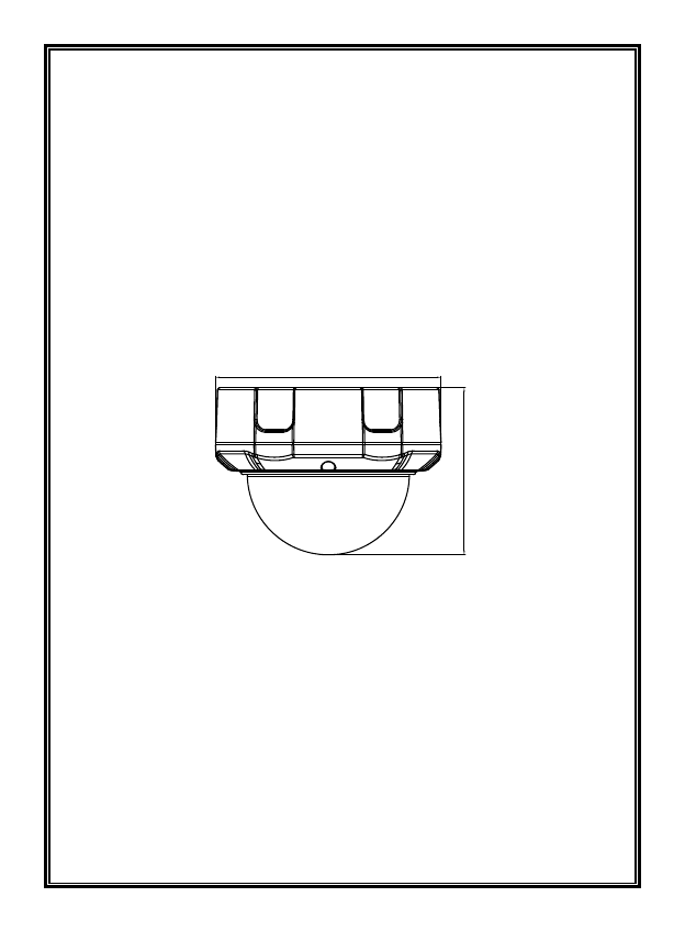
2.2 Dimensions
Unit: inch (mm)
4.02(102.1)
Ø5.43(137.8)
Figure 2-1 Surface-mounted Dome Camera
10
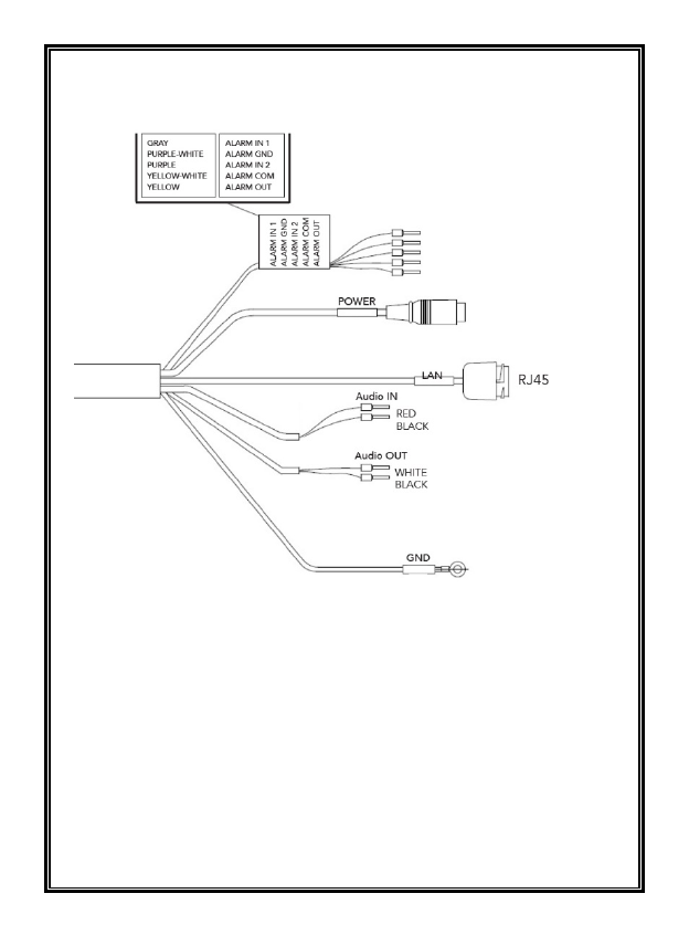
Cable Connections

11
Item
Description
LAN R
J-45
Ethernet, RJ
-45 port compatible with 10/100Mbps PoE
Power
Standard adapter jack for 12 VDC or 24 VAC
Alarm In
Alarm input and output, 5
-pin terminal
GND
Alarm Out
Alarm COM
Audio In
Audio input, 2
-pin terminal; line-level microphone
GND
Audio Out
Audio output, 2
-pin terminal; amplified speaker
GND
GND
Ground
2.3 Installing and Adjusting Camera
Select a location that is clear of obstacles and can support the weight of the unit.
Exercise maximum caution when installing the unit to the wall or ceiling the unit
falling can result in injuries and accidents. As a failsafe against falling, attach the
unit by chain, wire cable or other safety restraint to an appropriate anchor point.
Step 1: Prepare the mounting holes
To provide for cable management, the camera can be mounted to a back box,
model V940D-BOX or using an adapter plate to allow mounting to a 4x4
electrical box, model V940-PLATE.
Note: Make sure there is room for a cable routing hole at the location and drill a
hole to route the cables. Cabling should be routed to the installation location.
There is a desiccant bag in the dome. Do not remove this.
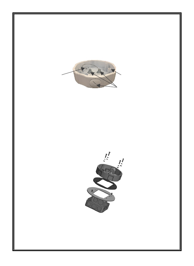
12
The V940D-BOX is supplied with a mounting template and hardware necessary
to mount it. Using the mounting template, prepare the three mounting holes.
Secure the box to the surface using the screws and anchors supplied or hardware
appropriate for the mounting surface. There are three cable access holes provided,
one on the side and two on the rear. Route the cables through one of these access
holes.
Loosen the three screws on the clear dome assembly to remove the clear bubble.
Note that there is a bag of desiccant inserted in the camera assembly; do NOT
remove this. Secure the camera dome to the standoffs in the back box using the
screws and washers provided in the accessory kit.
The V940-PLATE can be used to mount the camera dome to a standard 4x4
electrical box. Refer to the drawing below.
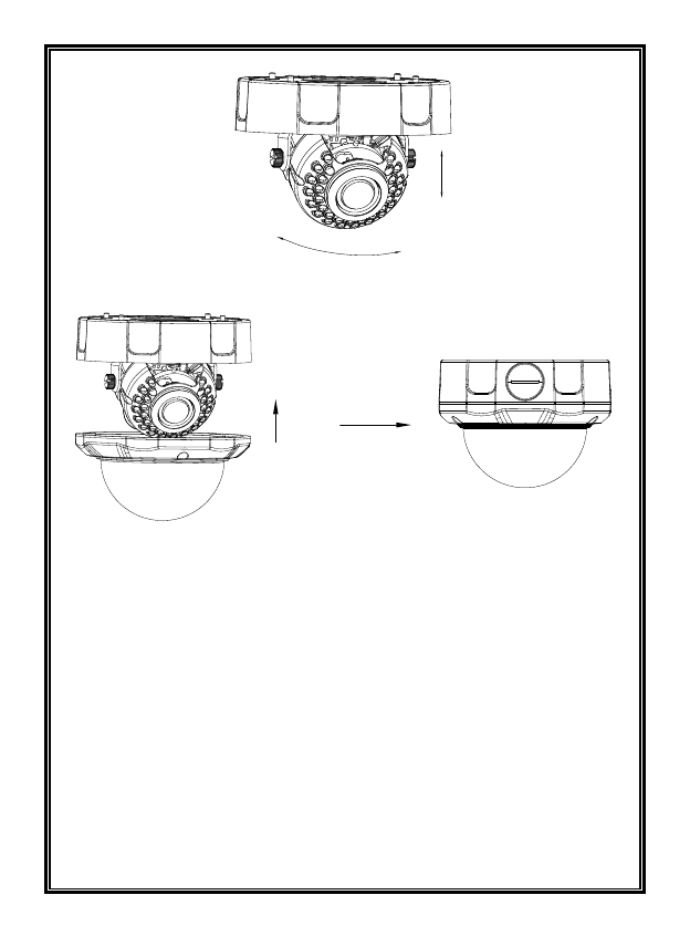
Step 2: Adjust the camera angle
Loosen the locking screws, adjust the camera angle and direction to the desired
position and then tighten the screws.
Cable access holes (3X)
Standoffs for camera mounting
(4X)
Mounting holes (3X)
13
Re-install the clear dome assembly to the camera and secure with the screws.
Connections
-
Connecting to the RJ-45
Connect a standard RJ-45 cable to the network port of the network camera.
Generally a cross-over cable is used for direct connection to PC, while a direct
cable is used for
connection to a hub. You can also use a router featuring PoE
(Power over Ethernet) to
supply power to the camera. An RJ-45 connector
protective cover is supplied in the accessory kit to protect the connection.
-
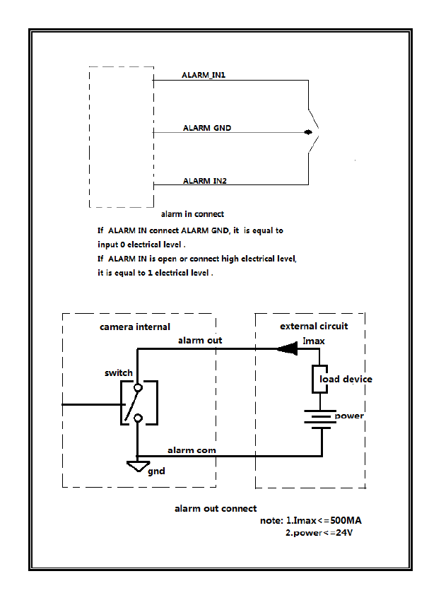
Connecting Alarms
There are two dry contact alarm inputs and one alarm output provided; the alarm
output acts as a switch to drive an external device, such as a light. Refer to the
figure below for connection and utilization of alarm input and output.
14

15
-
Connecting the Power
Connect the power for the network camera, 24 VAC or 12 VDC. For 12 VDC,
connect the positive (+) pole to the ‘+’ position and the negative (-) pole to the ‘-’
position for the DC power.
-
Be careful not to reverse the polarity when connecting a
12 VDC power cable.
-
A router featuring PoE (Power over Ethernet) can also be
used to supply power to
the camera.
-
Connecting Audio
There is one audio input and one audio output. Connect an external line level Mic
to Audio input and a Speaker to Audio output.

16
CHAPTER III IE BROWSER SETTINGS
3.1 Equipment Connection
V940D series camera can be connected directly to a computer or a network.
Note: Check that the connection is correct and secure before power-on.
3.2 Software Installation
The network camera is designed for use on an Ethernet network and requires an
IP address for access. Most networks today have a DHCP server that
automatically assigns IP addresses to connected devices. By the factory default,
your camera is set to obtain the IP address automatically via DHCP server. If
your network does not have a DHCP server the camera will us a link local IP,
i.e. 169.254.x.x.
If DHCP is enabled and the product cannot be accessed, run the Discovery Tool
utility to search for and allocate an IP address for the camera. The Discovery
Tool (IPCConfig.exe) can be found on Vicon’s website, www.vicon-
security.com, on the Software Downloads page for Vicon cameras.
Note: The approved browser for the camera is Internet Explorer*.
Depending on the version of Windows and IE, your screens may be slightly
different but similar in function.
Connect the network camera to the network and power up.
Start IPCConfig. The main window displays and the devices connected to the
network will display. Right click on the camera IP to open a browser. A login will
display.
*Supports Internet Explorer 8.0 or above, however, IE 10 or above is required for full functionality,
including the file upgrade function.
17
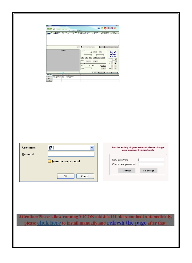
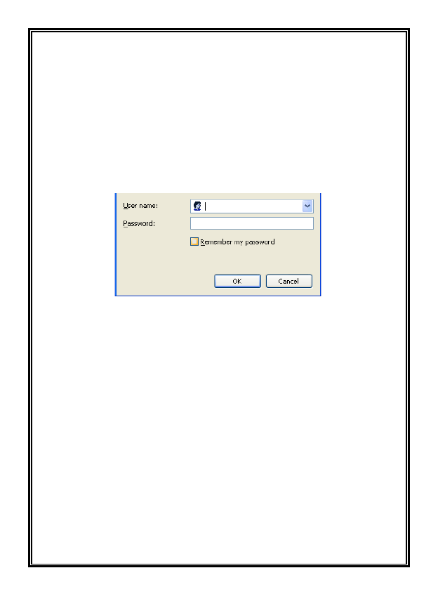
(1) Login
Enter user name and password in the pop-up login interface. For first time
users, the default admin login is ADMIN (case sensitive; password: 1234). For
increased security, it is recommended to change the password. After a
successful login, a screen will display to change the password; this can be done
here or using the Settings, Users screen. Select Change or No change. If no
change is selected you will open the Live camera interface.
(2) Install control
You may be prompted to allow running a Vicon add-in. Click to install manually
and run the add-in. Follow the prompts.
18
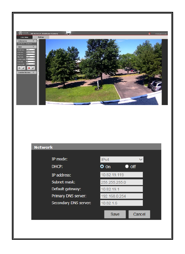
The Live View interface will display the major stream at H.264 format as
below:
Click the Settings tab and select Network. On this page (below), select Off to
turn off DHCP. Then enter the required IP address, Subnet mask and Default
gateway. DNS server is not required. Click Save and restart device. Click Yes
and exit IPCConfig.
19
CHAPTER IV BASIC FUNCTION OPERATION
This chapter will explain the settings and operation that the admin can perform
for the V940D Series.
4.1 Live View
After the server is powered on for about 90 seconds, open the IE browser, and
then enter IP address in the address field.
The user login interface is displayed as shown in figure below.
Figure 4-1 User Login
When running the software and logging in for the first time, use the default admin
username and password. The default User is ADMIN (uppercase, case sensitive)
and the password is 1234.
It is recommended to modify the password of the admin user to ensure the
safety and security of the system.
When the login is successful, the following interface will display:
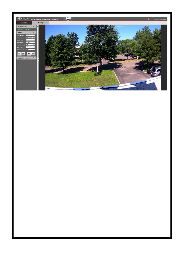
20
Figure 4-2 Live View
The V940D Dome Camera supports H.265, H.264 and M-JPEG video
compression formats. After the login, users will enter the Live view interface
displaying the major stream at H.264 format.
Stream Type: Users can select H.265 or H.264 from the Stream type dropdown
list.
Video Type: Users can select major stream, minor stream or M-JPEG from the
Video type dropdown list. In the H.265/H.264 major or minor stream type, users
can record and take a snapshot.
Video Size: Users can select a video scale from the dropdown (Fit, Full, 1x,
1/2x, 1/4x). Fit allows the video to be the size of the window without changing
the aspect ratio; Full spreads over the entire window and the aspect ratio
changes with the size of the window; 1X maintains the full resolution of the
video and 1/2x and 1/4x reduces the resolution by ½ or ¼, respectively.
Play Mode: Users can select Live or Smooth; Smooth will produce an image
with less noise and better quality.
Corridor Mode: When the mode is enabled, the horizontal angle narrows
while the vertical angle stretches, as shown in Figure 4-3.
Note: 90°clockwise rotation is needed for angle adjustment when using
corridor mode.
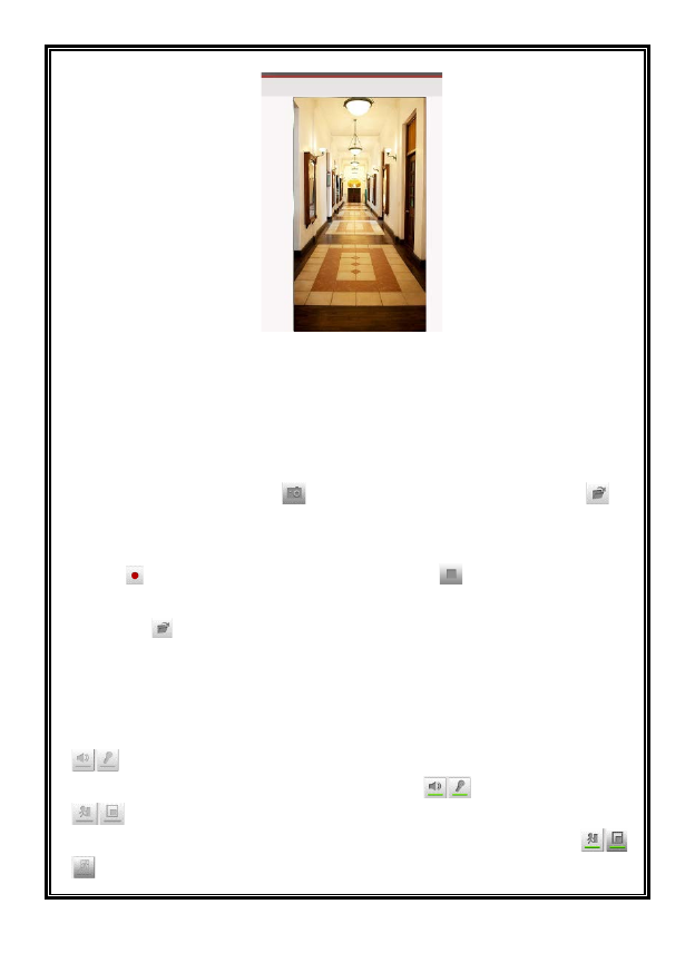
21
Figure 4-3 Corridor Mode
Video Info: Show or hide video information (Bite rate and frame rate). If the
video type or stream type is changed, video info is set to off automatically.
Video Profile: For H.264 stream type, the video profile can be set to High,
Main or Base.
Snapshot: Click the button to take a snapshot. Click the button to
access the saving path of the snapshot; default: C:\VideoPlayerAX\Picture.
Local recording: V940D Series supports local recording. Click the recording
button to start recording; the button changes to ; click the button to stop
recording. During local recording, “REC” appears on the video screen. Click
the button to enter the recording storage path; default: C:\VideoPlayerAX\
Video.
Users can set the snapshot and recording storage path in the Audio & Video
settings interface.
Function buttons:
Indicate audio input/output are disabled. Click the buttons to enable
audio input/output; the buttons will be shown as .
Indicate that the motion detection and privacy mask functions are
disabled. Click the buttons to enable them; the buttons will be shown as .
Indicates that the Video Content Analysis functions are disabled. Click the
22
button to enable them; the button will be shown as 。
Note: The motion detection and privacy mask settings can only be set in the
Live view settings interface when they are enabled in the Audio & Video
Settings. Refer to Sections 4.5.3 or 4.5.4 for details.
Note: The login web page language should be set to the same as that of PC's
operating system.
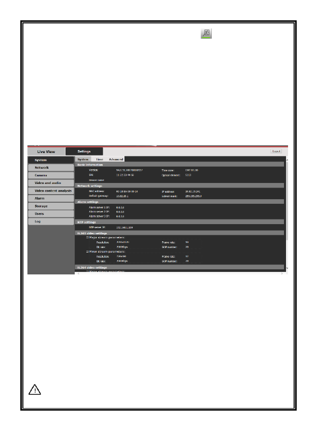
Click the option tab “Settings” to enter the system Settings interface.
Figure 4-4 Settings Interface
Using the navigation menu on the left, admin can perform the following
operations: Basic Information view, Time settings and Advanced settings,
Network settings, Camera settings (including Basic Set, Exposure Set, Effect Set,
White Balance, Focus, IR Set, Reset), Video and Audio settings, Video Contents
Analysis, Alarm settings, Storage settings, Users settings (Add/Delete User,
Change Password), Log, etc.
Note: The following instructions are for the admin use.
23
4.2 System
Click “System” in the left navigation bar to display the following three option
tabs: System, Time and Advanced, as shown in Figure 4-4.
4.2.1 System Information
The initial interface of System settings displays related system information, such
as Basic system information, Network settings, Alarm settings, NTP settings,
H.265/H.264/MJPEG video settings, etc.
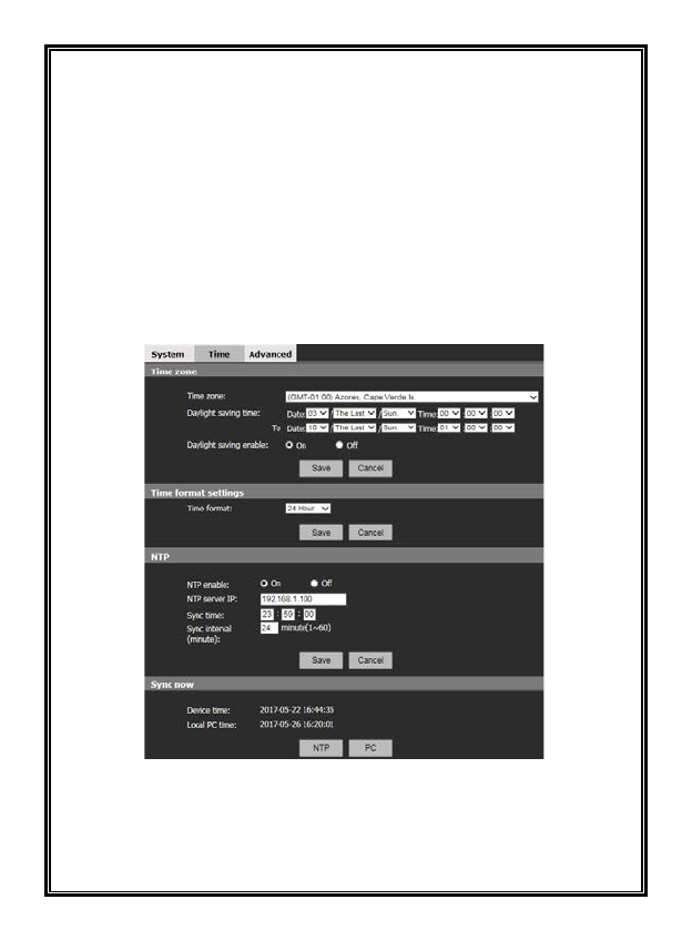
4.2.2 Time Settings
Figure 4-5 Time Settings
Time Zone Settings
Time Zone: Select the desired time zone from the dropdown list. There are 33
time zones available to select from.

24
If Daylight Saving Time is used in the location, users can enable the Daylight
saving option by selecting the On radio button and enter the correct dates for the
daylight saving time period.
When settings are completed, click “Save.”
Time format settings
Select the time format from 24 hour or 12 hour. The date format can be set as
MMDDYYY, DDMMYYYY or YYYYMMDD in the OSD menu.
When settings are completed, click “Save.”
NTP Settings
To set the NTP, check the On radio button; select Off if this will not be used. Set
NTP server’s IP address and synchronization time and interval parameters.
When settings are completed, click “Save.”
Sync now
There are two sync modes: local PC sync and NTP sync.
PC sync means the device time is consistent with that of local PC. In the NTP
sync mode, the system will check time with the NTP server automatically to
adjust time.
Be sure to save settings before leaving the interface or cancel any changes made.
25
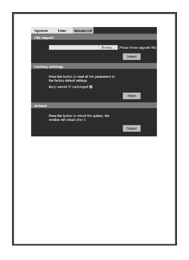
4.2.3 Advanced Settings
Figure 4-6 “Advanced” Settings
Software Update
Free software updates are provided for V940D Series cameras on the Vicon
website on the Software Downloads page and can be downloaded to a PC or other
media device.
Follow the steps below to update software:
Under File import, click “Browse” button on the interface and the file selection
dialog box will pop up.
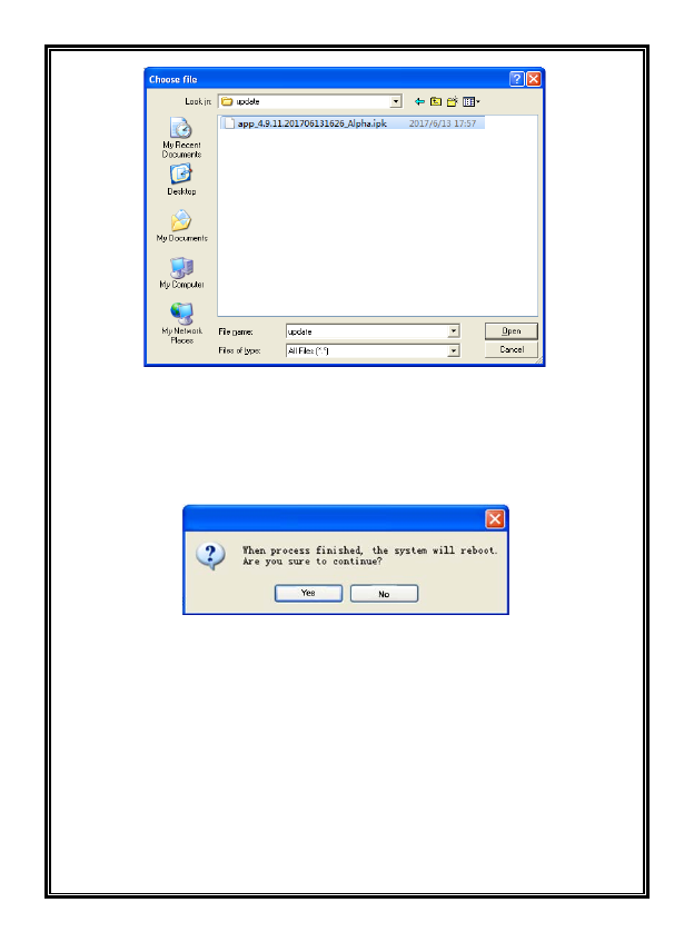
26
Figure 4-7
Select update file and press “Open” button. The selected update file will be
displayed in the Software Update box. Click “Submit” button to update software;
the following information will appear:
Figure 4-8
Click “Yes” button and run the program to finish the update.
The response time depends on the program type; it may take a long time for some
programs. Do not power off during the update process; power-off will cause the
update to fail or damage the original program or disrupt update again.
After a successful update, a reboot of the system is required. There is a time
prompt in the web page during reboot. After reboot, a new web page will open to
run new program.
Note: This is only available for the admin.
27
Factory Settings
V940D Series cameras provide an online reset function, which greatly facilitates
reset adjustment.
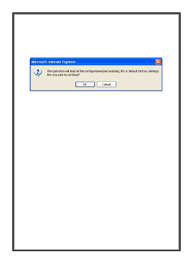
Select “Keep current IP unchanged,” click “Reset” button and the system will
pop up the message to confirm factory reset:
Figure 4-9
Click “OK;” all the parameters (excluding IP address) will be reset to the factory
default settings.
If “Keep current IP unchanged” is unselected, the IP address will be reset to
DHCP mode.
There is time prompt in the web page during reset. After reset, a new web page
will open.
Note:
1. To avoid any errors, the online reset function operation should be performed
under qualified personnel’s guidance.
2. Do not power off during reset or the reset will fail.
Online Reboot
Click “Reboot” button; the dialog box “This operation will take 90 seconds, are
you sure to continue?” will pop up. Click “OK” and the system will restart.
There is a time prompt in the web page during reboot. After reboot, a new web
page will open.
Note: This is only available for the admin.
28
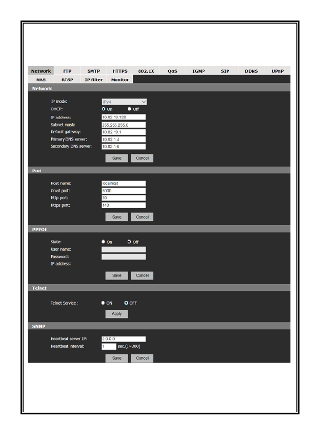
4.3 Network Settings
Click “Network” in the left navigation bar; the following interface will display:
Figure 4-10 Network Settings
There are 14 option tabs for settings: Network, FTP, SMTP, HTTPS, 802.1X,
QOS, IGMP, SIP, DDNS, UPnP, NAS, RTSP, IP Filter and Monitor.
29
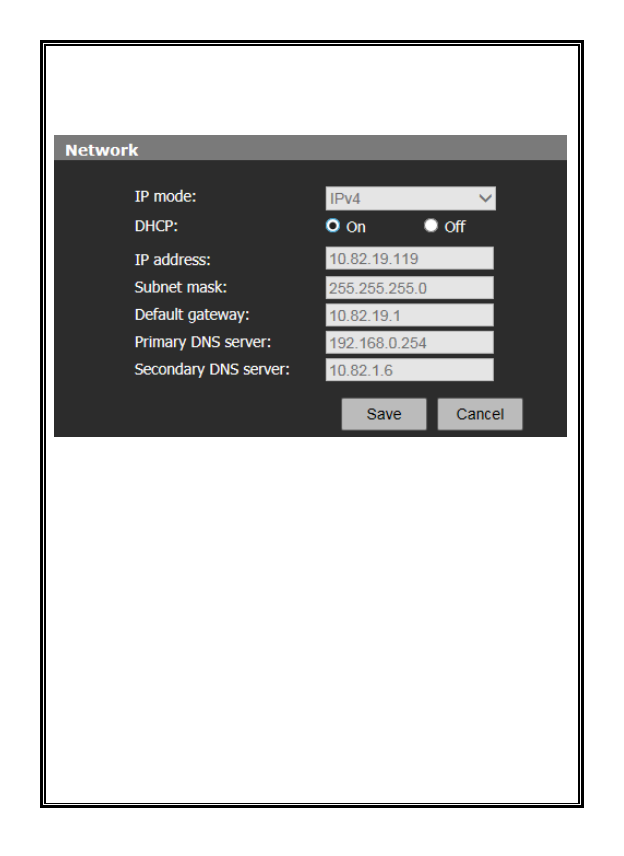
4.3.1 Network Settings
IP mode: There is support for both IPv4 and IPv6 modes. The configuration of
Network parameters will differ depending on the mode selected.
Figure 4-11 Network Settings
Users can enable (On) or disable (Off) DHCP. When it is disabled, users can set
unit IP address, Subnet mask, Gateway and DNS server IP address manually.
Note: The system indicator quickly flickers for 5 seconds after the network
settings are completed successfully.
Enter Host name and Port settings for Onvif, Http and Https.
Users can enable/disable PPPoE in this interface. If enabled, users can set the
user name and password.
Telnet service can be turned On or Off as required.
In SNMP settings, the cameras support a heartbeat function. Set and save the
Heartbeat server IP address and Heartbeat interval; the heartbeat package will be
sent to the server or client, which greatly facilitates the server or client to know
about the camera’s network status.
Be sure to save settings before leaving the interface or cancel any changes made.
30
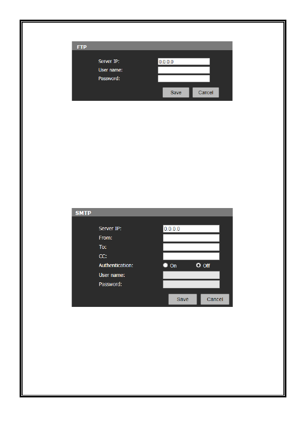
4.3.2 FTP Settings
Figure 4-12 FTP Settings
V940D cameras support the function of alarm associated FTP image upload
(alarm triggered image snapshot). Configure server IP, user name and password
in the FTP settings. Then activate the alarm associated FTP uploading function
in the alarm setting interface to activate the FTP image uploading function upon
alarms.
4.3.3 SMTP Settings
Figure 4-13 SMTP Settings
The cameras support the function of alarm associated email sending. The email
server and receiver information are set in the SMTP setting interface.
- Server IP: Set mail server address.
- From: Set sender’s mail address.
- To: Mail address of recipient.
31
- CC: Mail address of the recipient of a copy.
- Authentication: Enable or disable authentication function. This function
should be set according to authentication requirements of mail server.
- User name: Sender’s name; this can be set according user’s needs.
- Password: Set sender’s password.
Note: There is no limit for Sender’s name and password settings.
After setting, click “Save” for settings to take effect.
If user selects “Mail” in “Alarm Settings” interface, system will send emails
according to SMTP settings.
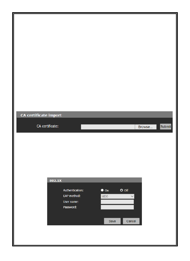
4.3.4 HTTPS Settings
Figure 4-14 HTTPS Settings
V940D camera supports HTTPS protocol. Import the CA certificate in the
interface. Be sure to save settings or cancel any changes made.
4.3.5 802.1X Settings
Figure 4-15 802.1X Settings
32
V940D Series supports 802.1X protocol. Enable 802.1X authentication when
needed. Then, select an EAP method and enter the user name and password.
Be sure to save settings before leaving the interface or cancel any changes made.
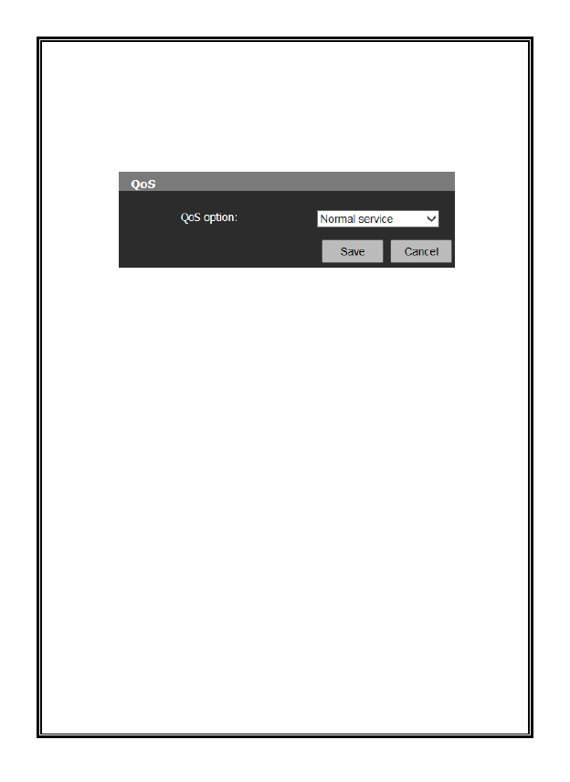
4.3.6 QoS Settings
Figure 4-16 QOS Settings
Select the network service quality in the QoS setting interface. There are 4
network QoS modes:
(1) Normal service
(2) Max reliability
(3) Max throughput
(4) Min delay
Recommended/Default: Normal service.
Be sure to save settings before leaving the interface or cancel any changes made.
33
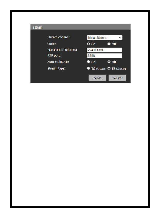
4.3.7 IGMP Settings
Figure 4-17 IGMP Settings
V940D cameras support multicast function. In the IGMP interface, users can
select the stream type and set the state, multicast IP address and RTP port. For
auto multicast, users can set the status as On or Off and set the stream type as TS
stream or ES stream.
34
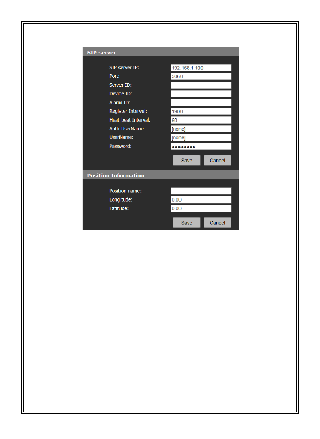
4.3.8 SIP Settings
Figure 4-18 SIP Settings
SIP server: Configure SIP server for device:
SIP server IP: IP address of SIP server
Port: Port number of SIP server
Server ID: ID of SIP server
Device ID: Device ID used for registration with SIP server
Alarm ID: ID registered for device alarm
Register Interval: Interval for re-registration of device in seconds
Heart beat Interval: Interval to send heartbeat information by the device in
seconds
After configuration is completed, click “Save” and the device sends a registration
request to the server.
35
Position Information: Mounting information or instruction for device.
Enter a position name.
Longitude: Longitude of mounting position, precisely to two decimal places
Latitude: Latitude of mounting position, precisely to two decimal places
Be sure to save settings before leaving the interface or cancel any changes made.
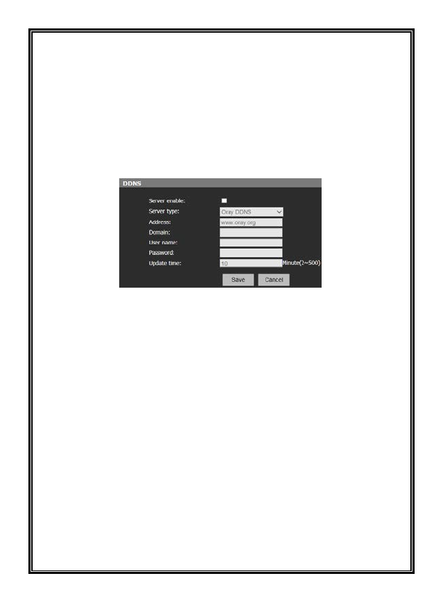
4.3.9 DDNS Settings
Figure 4-19 DDNS Settings
Dynamic Domain Name System (DDNS) can enable continuous synchronization
of the host name and dynamic IP address. Users only need to input the dynamic
domain name to connect to a network camera instead of memorizing the dynamic
IP address.
To employ this method, a PC with a static IP address needs to be available and,
additionally, a dynamic domain name server must be running at the PC.
Operation: Select the Server enable option and then select the DDNS type. Enter
the IP address of the DDNS server into the address bar, configure Domain, User
name, Password and Update time. Then Save the settings. Open the IE browser,
enter the domain name to access the web search page of the device.
Be sure to save settings before leaving the interface or cancel any changes made.
36
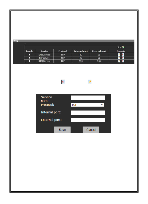
4.3.10 UPnP Settings
A mapping relation between a private network and an external network is built
via UPnP protocol. Select UPnP option to enter the configuration page. The
mapping list added will appear on the page.
Figure 4-20UPnP Settings
Click the Enable box to select a type of service.
In the “Operate” column, click to delete and to edit user information.
Click Add button to add a mapping.
Figure 4-21
Be sure to save settings before leaving the interface or cancel any changes made.
37
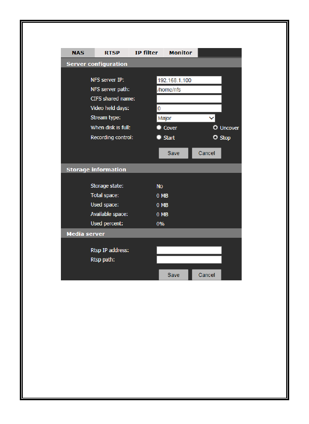
4.3.11 NAS Settings
Figure 4-22
The camera supports NAS (Network Attached Storage) function that allows you
to save the recorded videos on the network server.
Server Configuration: Set the NFS server IP, NFS server path, CIFS shared name,
video held days, stream type, what to do when disk is full and recording control.
Storage Information: View the storage state, total space, used space, available
space and used percent.
Media Server: Set the Rtsp IP address and Rtsp path. Be sure to save settings
before leaving the interface or cancel any changes made.
38
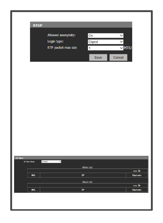
4.3.12 RTSP
Figure 4-23 RTSP Setting
Allowed anonymity: If “On” is selected, there will be no need for the client to
have user authentication when a video by RTSP is requested.
Login Type: Select Login Type from the drop-down menu. Choose Digest
(system uses encryption information to verify user password). You need to set
Login Type when Allowed anonymity is “On.”
RTP Packet max size: Select the maximum size of standard data packet with
“byte” as its unit.
Be sure to save settings before leaving the interface or cancel any changes made.
4.3.13 IP Filter
The IP filter interface allows you to add IP addresses that have access permission
(i.e., White List) and those that do not have access permission (i.e., Black List)
and to configure the IP Filter Mode.
Figure 4-24
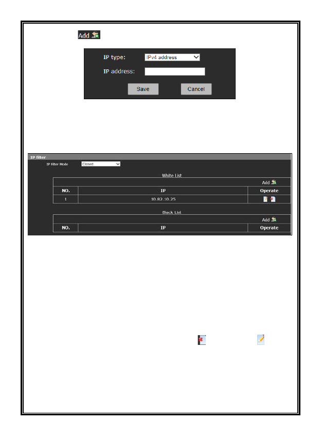
39
Click the icon to add IP address on the popup page.
Figure 4-25
Click the Save button after an IP address is added. Then the added IP address
will appear in the appropriate IP list.
Figure 4-26
If you select the White List mode under the IP Filter Mode, only the IP addresses
that are added to the white list are able to be accessed. If you select the Black
List mode under the IP Filter Mode, the IP addresses that are added to the black
list cannot access the device. Selecting Closed means there is no choice.
Note: If the white list mode is selected, a valid IP address must be available; be
sure to remember the IP address.
On the IP list, in the Operate column, use the icon “ ”to delete and “ ”to edit.
40
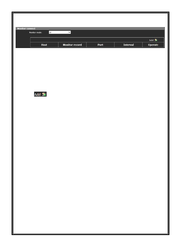
4.3.14 Monitor Connect
Figure 4-27 Monitor Connect
You can monitor connection status of devices and platform on the Monitor
connect page. You can also use settings on the Alarm page to assure automatic
recording when disconnecting.
Procedures:
1. Click icon to set Host IP (the IP of computer where the server
platform is located), Port and Interval.
2. On Alarm page, select Heart Beat Lost and SD Card and then set alarm time.
For more information, see “Alarm Settings” in section 4.7.
3. SD card will record automatically when a disconnection between devices and
platforms is monitored, and it stops recording one minute after the devices and
platforms reconnect.
Monitor Mode: “Or” and “And” are selectable. When the monitor mode is “Or,”
SD card will be enabled when one of the platforms disconnects; when the monitor
mode is “And,” SD card will be enabled when all of the platforms disconnect.
41
4.4 Camera Settings
Click “Camera” in the navigation bar to enter the interface shown below:
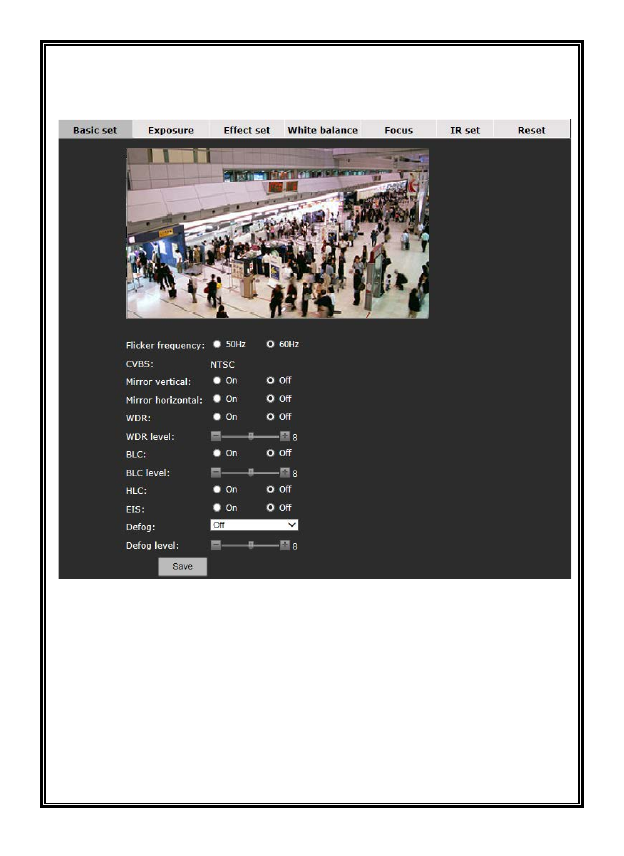
Figure 4-28 Basic Settings
There are option tabs included in the camera settings page: Basic set, Exposure,
Effect set, White balance, Focus, IR set, Temperature and Reset.
4.4.1 Basic Settings
Basic settings allows the following parameters to be configured:
Flicker frequency: 50Hz or 60Hz.
CVBS: Automatically changes depending on the flicker frequency. (Note: analog
42
videos are shut off after MJPEG stream is enabled. To enable analog videos,
disable MJPEG stream.)
Enable or disable (On/Off): mirror vertical, mirror horizontal, WDR, BLC, HLC
and EIS (stabilization).
Defog: Optional, set to Auto or Off.
Defog level: If set to Auto, set the defog level, 0~255.
Be sure to save settings before leaving the interface or cancel any changes made.
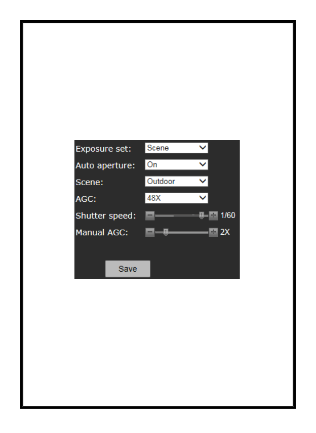
4.4.2 Exposure Settings
Figure 4-29 Exposure Settings
From this screen, set Exposure set, Auto aperture, Scene, AGC, Shutter speed
and Manual AGC.
Exposure Set: Select Manual, Scene and Shutter Priority from the dropdown.
Auto Aperture: Enable or disable autoiris (On/Off).
Scene mode: Indoor or outdoor can be selected.
AGC: Select from 8X, 16X, 32X, 48X, 64X options; if set to Manual Exposure
mode, Shutter speed can be set from 1/30s to 1/10000s and manual AGC can be
set as 1X, 2X, 4X, 8X, 16X, 32X, and 64X, but then scene and AGC are not
adjustable; if set to Shutter priority mode, the Min shutter speed
43
(1/100s~1/32000s adjustable), Max shutter speed (1/1s~1/32000s adjustable) and
AGC can be set.
Be sure to save settings before leaving the interface or cancel any changes made.
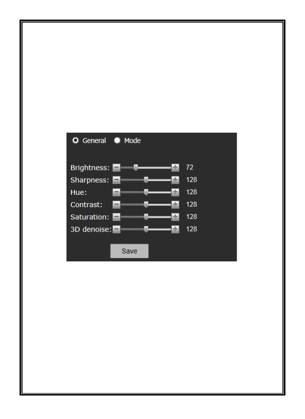
4.4.3 Effect Settings
In the Effect Settings interface, users can adjust the brightness, sharpness, hue,
contrast, saturation and 3D de-noise (DNR) in two ways, General or Mode, as
shown in the figure below:
Figure 4-30 Effect Set - General
General: Drag the sliding block to adjust the brightness, sharpness, hue, contrast,
saturation and 3D de-noise (DNR) parameters.
44
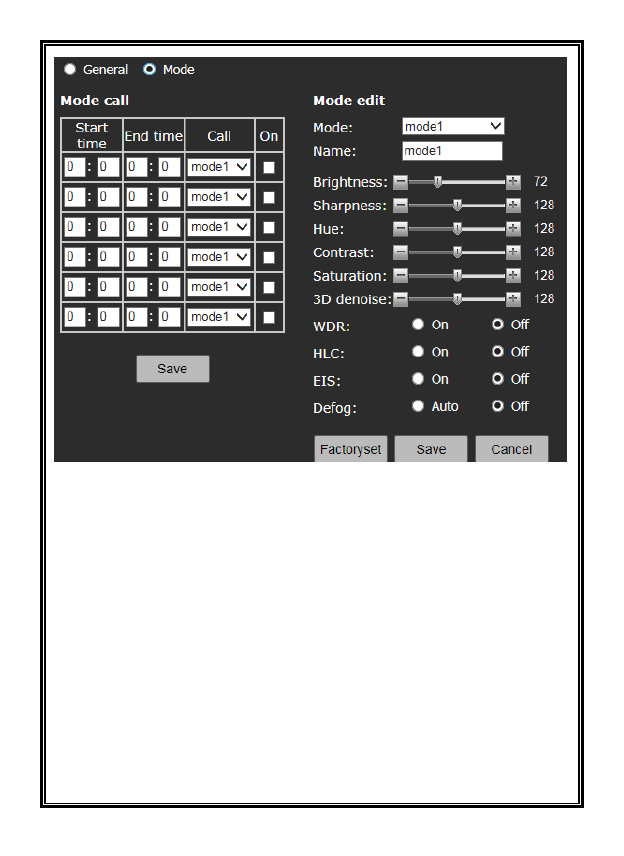
Figure 4-31 Effect Set - Mode
Mode: The camera supports 6 video effect modes. Users can set and save a Name,
Brightness, Sharpness, Hue, Contrast, Saturation, 3D de-noise, WDR, HLC, EIS
and Defog for each mode. Click “Factoryset” to restore default settings.
In the Mode call, users can set Effect Mode call status and start and end period.
Be sure to save settings before leaving the interface or cancel any changes made.
45
4.4.4 White Balance
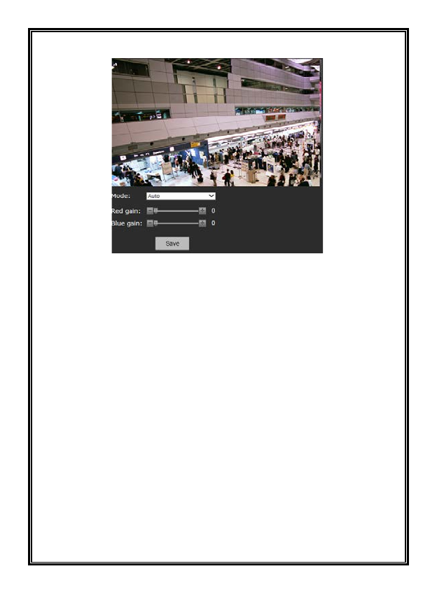
Figure 4-32 White Balance Settings
The camera has a selection of white balance modes, including Auto (used for
outdoor) and Manual. If set to Manual mode, the red gain and blue gain can be
set using the sliders.
Be sure to save settings before leaving the interface or cancel any changes made.
46
4.4.5 Focus Settings
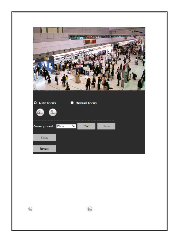
Figure 4-33 Focus Settings
The camera has a built-in motorized zoom lens for remote focal length
adjustment. Click “Focus” in camera settings interface to enter focus settings.
On this page, select focus mode, zoom/focus and call focus limit.
Auto focus:
In auto focus mode, the interface is shown as Figure 4-33.
Click button to focus wide; click button to focus tele.
Click Stop button during focusing to stop auto focus.
47
Left-click in one section of the video; the frame of this section will turn to green
and the camera will automatically focus for this area.
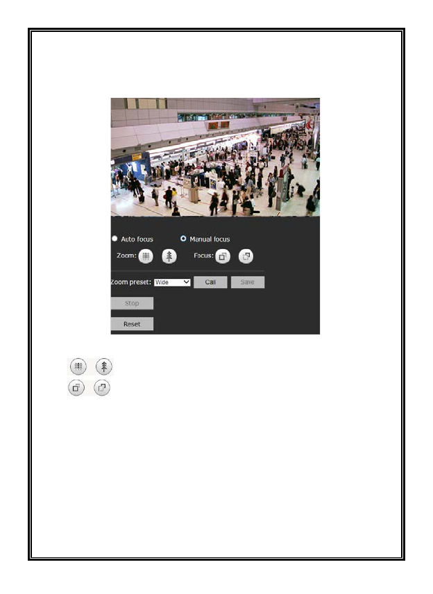
Manual focus: Click Manual focus to enter the interface shown below.
Figure 4-34
Click to zoom wide/zoom tele.
Click to focus near/focus far.
Zoom Preset: The camera can call a zoom preset. There are 5 options: Wide,
Middle, Tele, User set 1, User set 2. The effects for Near, Middle and Far are
default; but User set 1 and User set 2 can be specified by users.
Reset: If the camera cannot focus clearly using auto focus, click Reset button to
restart the motor.
Be sure to save settings before leaving the interface or cancel any changes made.
48
4.4.6 IR Set
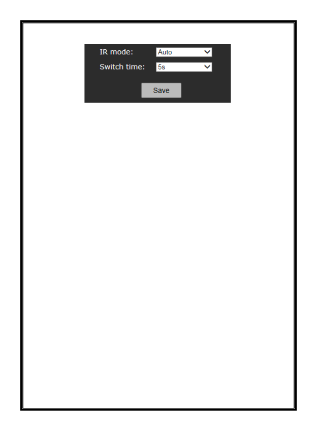
Figure 4-35
IR mode: Set IR illuminators working mode, Auto.
Options: Day, Night, Auto (turn on or off as per ambient light).
Switch time: In auto mode, the response time for day/night switch.
Power Set: Select Auto to use the Smart IR function. Select Manual to use the
Power Control slider to adjust the IR.
Be sure to save settings before leaving the interface or cancel any changes made.
4.4.7 Temperature: The fan can be turned on or off. Select Auto, which will turn
the fan on at a specific temperature, On, to turn the fan on manually, or Off.
4.4.8 Reset
From this interface, restore all the camera parameters to the factory default
settings.
49
4.5 Video and audio Settings
Click the button Video and audio in the navigation bar to display the following
interface.
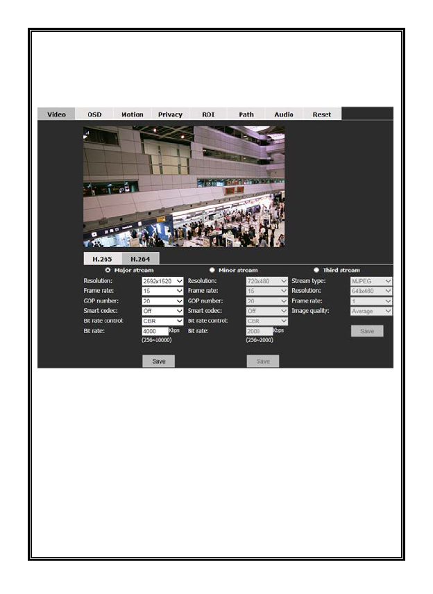
Figure 4-36 Video Settings
The Video and audio Settings page allows setting Video, OSD, Motion, Privacy,
ROI, Path, Audio and Reset.
Click the related option tab to enter the setting interface.
4.5.1 Video Settings
Users can set the video parameters for H.265, H.264 and MJPEG stream,
including resolution, frame rate, GOP number, and bit rate. Note that H.265 must
be selected for the major stream on the Live View for it to display here.

50
Resolution for H.265/H.264 major stream:
The resolution of the 4 MP camera is up to 2592×1520, with 2560×1440,
2048×1520, 2304×1296, 1920×1080, 1280×960 and 1280×720 options.
The resolution of 2 MP camera is up to 1920×1080, with 1280×960 and
1280×720 options.
Resolution for H.265/H.264 minor stream:
The resolution is up to 1920×1080, with 1280×960, 1280×720,
720×576/720×480, 704×576/704×480, 640×480, 352×288/352×240, 320×240
and closed (turn off) options.
Resolution for third stream:
For the third stream, the stream type can be set as H.264, H.265 and MJPEG.
The resolution can be 640×480/352×240/320×240.
Frame Rate: This is the number of compressed frames produced by the camera
per second. The larger the frame rate is, the better the image continuity will be,
but the CPU performance is lowered. The smaller the frame rate is, the worse the
image continuity will be, but the CPU can handle more events.
The maximum frame rate for H.265 and H.264 is 30fps. The maximum frame
rate for MJPEG is 5fps.
The Max. Encoding Capacity of 4 MP camera is
2592×1520@20fps+720×480@30fps+ MJPEG640×480@5fps.
The Max. Encoding Capacity of 2 MP camera is 1080P@30fps+720P@30fps+
MJPEG 640×480@5fps.
GOP number: GOP number is the ratio of I frame (complete image) to P frame
(changes in image) in compressed video images. The larger the value is, the less
the data quantity is and the less network resource it occupies.
Max. GOP number can be set to 60.
Smart Codec: Select Off/Low/Middle/High. This determines the level of bit
rate reduction.
Bit Rate: There are 2 modes of bit rate: variable rate (VBR) and constant rate
(CBR).

51
With variable bit rate, the system can automatically adjust the bandwidth of the
images per the complexity of the images. In practical use, the complexity of the
video images varies constantly, as the details of the scene and the moving speed
change. If the video includes too much detail and images in it move fast, then the
bandwidth it uses will be larger. If not, the bandwidth is smaller. If the Bit Rate
is set as “Constant bit rate,” then the images are transferred by fixed bandwidth
capacity, no matter how the complexity of the images changes.
Bit Rate: If “VBR” is selected, the upper limit of bit rate has to be set; if
“CBR” is selected, the stream size will be fixed and the stream size is defined
in the “Bit Rate.” For major stream, the bit rate upper limit can be
256kbps~10000kbps; for minor stream, the bit rate upper limit can be
256Kbps~2000Kbps.
Image Quality: Set under MJPEG (third) stream. Options: Highest, High,
Average, Low and Lowest. The higher the image quality is, the more bandwidth
it will use.
Be sure to save settings before leaving the interface or cancel any changes made.
52
4.5.2 OSD
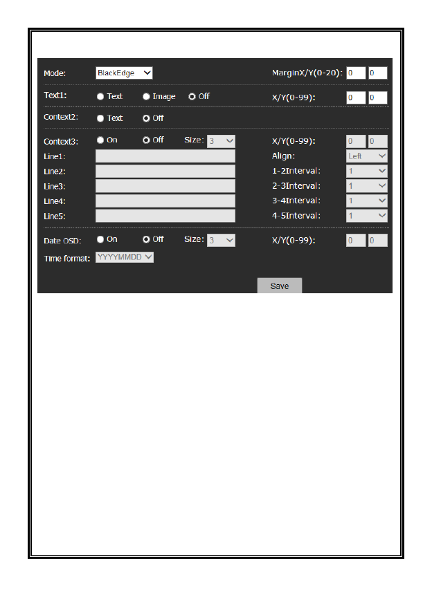
Figure 4-37 OSD
From the OSD (On Screen Display) screen, set Text 1, Context 2, Context 3 and
date to display on the video image.
Mode: BlackEdge (text has a black outline) or SingleColor.
Margin: Set the margin of the text overlay area from the edge of image; 1
indicates one-tenth character size and 10 indicates one character size. For
example, set X to 10 and Y to 20, which means the left side of text area is only
one character size from the left edge of image and the upper side of the text area
is 2 character sizes from the upper edge of the image.
Note that the size of overlay characters can be set separately. When the character
sizes are not the same, the actual margin size is different, even if the same margin
is set. For example, for Context 3, if the font size is set to 3 point, a margin of 1
indicates the size of one-tenth of 3 point font; for Text 1, if the font size for text
is set to 8 point, the margin of 1 indicates the size of one-tenth of 8 point font.

53
Text 1: Text or Image options or turn the option Off.
Text: Select Text and enter the text content in the content box, which allows up
to 40 characters (a~z, A~Z and 0~9). Also set the font size and text coordinates
(where the text will display on the screen).
Image: The camera supports image overlaying on the video, for example
inserting a logo. Click Image to set the image overlay information. Click the
Browse button, select the image to be uploaded, and then, click Upload. Drag the
slider for transparency to adjust the image transparency. Select “Clean white” to
make a transparent background for the image. Additionally, set the coordinates
for the image for where it will display.
Notes:
(1) A bitmap image is required.
(2) The maximum size of image is 352×288, with both the width and height
required to be an even number, such as 160×130.
Context 2: Select “On” and enter the text content in the text box, which allows
up to 40 characters (a~z, A~Z and 0~9). Also set the font size and text coordinates.
Context 3: Select “On” and enter the text content in the text box from line 1 to 5,
which allows up to 40 characters (a~z, A~Z and 0~9). Also set the font size and
text coordinates.
Align: Multiple lines of texts can be aligned at the left or right. Set the interval
between two lines that are next to each other; 1 indicates the one-tenth size of a
character.
Note: X/Y Coordinate: Set the coordinates of text. For text 1, Context 2 and
Context 3, the origin of coordinates is the upper left corner of the text display
area.
54
Date OSD: Select “On” and set the font size, display position and format
(MMDDYYY, DDMMYYYY or YYYYMMDD). Size: Set the character size of
the text. The larger value indicates larger character size.
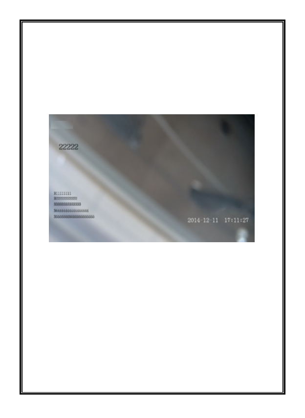
After settings are finished, click the “Save” button. The OSD displays on the
video. To cancel OSD, click “Off” and “Save” button.
The OSD is displayed as below:
Figure 4-38
55
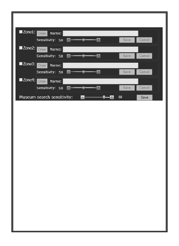
4.5.3 Motion Detection
Figure 4-39 Motion Detection Settings
The motion detection function is supported. Up to 4 motion zones can be
configured.
Note: Turn on motion detection function in Live View interface before motion
detection setting (see Section 4.1).
Check the box of the Zone number to be set. If this motion detection area has
already been set, a blue frame will be displayed on the screen.
Setting the motion detection area:
Check the box of motion detection area number. Click the “Draw” button with
the mouse and then left click on the mouse and draw a blue frame on the screen.
Then, click the “Save” button to save the zone; the blue frame will turn green,
indicating the setting is complete.
Enter the area name in the Name field and use the slide bar to set the sensitivity;
moving the slide towards the plus sign heightens the sensitivity for detection.
To cancel a motion detection area, uncheck the box.
56
Museum search, one of the recorded video playback search functions, allows
the search for moving objects in recorded video. Museum search sensitivity is
the threshold for regulating the smallest moving range objects that can be
searched. Use the slide bar to adjust the Museum search sensitivity.
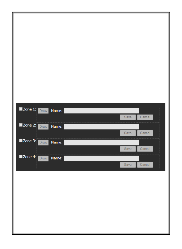
4.5.4 Privacy Mask
V940D Series camera supports 4 privacy masks. If certain sensitive areas within
the surveillance area should not viewed, a Privacy Mask can be applied. The
camera system covers and shields the sensitive area via Privacy Mask setting to
prevent operators from observing this location.
Note: Turn on the privacy mask function in Live View interface before privacy
mask setting (see Section 4.1).
Figure 4-40 Privacy Mask Settings
How to set the privacy masks:
Check the box of privacy Zone number. Click the “Draw” button with the
mouse and then left click on the mouse and draw a blue frame on the screen.
Then click the “Save” button and the blue frame changes into black, masking
that area of the image.
To cancel a privacy mask, uncheck the box.
57
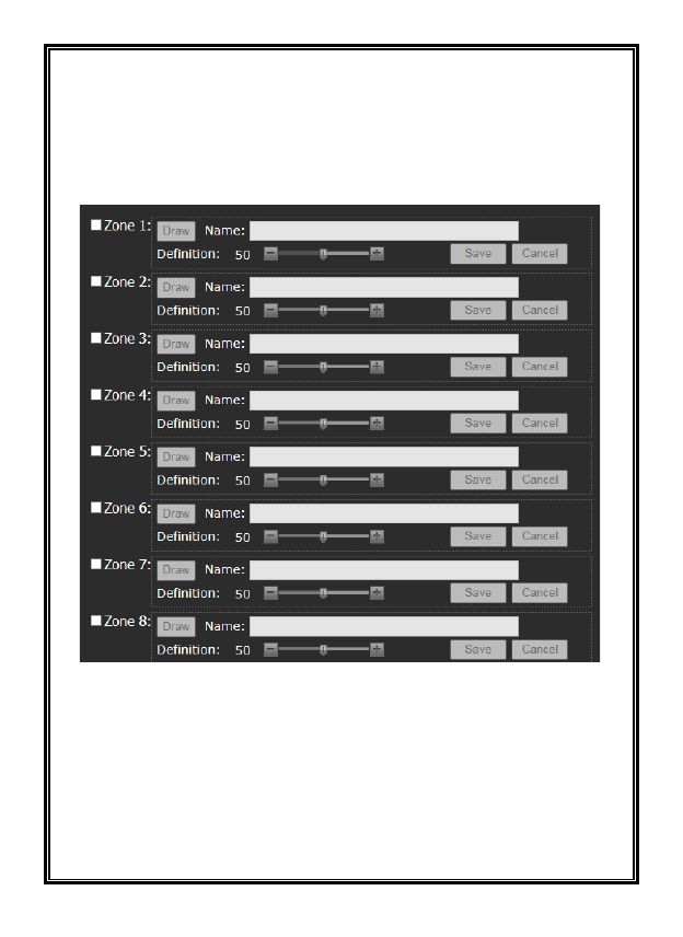
4.5.5 ROI
The camera supports ROI (Region of Interest) function, with eight zones settable.
The areas selected are of particular importance in the scene, for example a face
or license plate. When this enabled, the selected areas will be encoded to include
more detail.
Figure 4-41 ROI Settings
ROI settings method:
Check the Zone number of the region for setting and click the “Draw” button.
Left click on the mouse and draw a blue frame on the screen. Click the “Save”
button and when the color of the regional border changes from blue to green,
ROI setting is complete. Use the slide bar to adjust the definition of the region.
To cancel an ROI, uncheck the box.
58
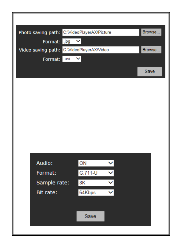
4.5.6 Storage Path
Figure 4-42 Storage Paths
The default photo saving path: C:\VideoPlayerAX\Picture.
The default video saving path: C:\VideoPlayerAX\Video.
The photo and video formats can be set. The default photo format is .jpg and
the default video format is .avi.
To change the saving path, click the “Browse” button and select the path from
the popup dialog box.
Be sure to save settings before leaving the interface or cancel any changes made.
4.5.7 Audio Settings
Figure 4-43 Audio Settings
59
Audio: ON or OFF options.
Format: G.711-U, G.711-A and AAC.
Sample rate: For G.711-U, G.711-A, sample rate is 8K; for AAC, sample rate
options are 16K, 32K, 44.1K, 48K.
Bit rate: For G.711-U, G.711-A, bit rate is 64Kbps; for AAC, bit rate options are
32K, 64K.
4.5.8 Reset
From this interface, restore all the camera parameters to the factory default
settings.
4.6 Video Content Analysis Functions
Click the “Video Content Analysis” button on the left navigation bar. The setting
page for the VCA functions shows as below:
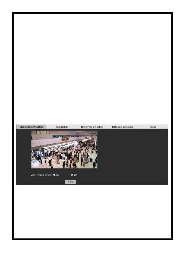
Figure 4-44 Settings of Video Contents Analysis Functions
From the Video Content Analysis tab, turn on Video Content Setting and set
Camera Tampering, Line Cross Detection and Intrusion Detection. Click the tabs
respectively to enter each setting page.
In the VCA setting page, users can enable or disable the VCA function to allow
setting the other functions. Save this setting.
60
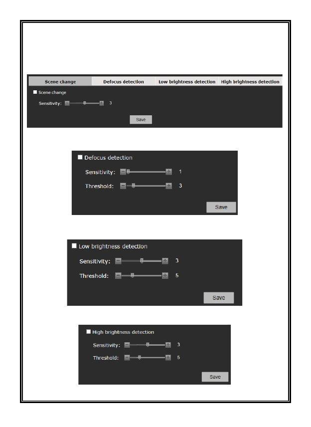
4.6.1 Camera Tampering
From this screen, set the sensitivity for scene changes, defocus detection and low
or high brightness detection.
Figure 4-45 Scene change
Figure 4-46 Defocus detection
Figure 4-47 Low brightness detection
Figure 4-48 High brightness detection
61
Scene change: When the monitoring scene changes, an alarm is triggered.
Defocus detection: When focus is not clear, an alarm is triggered.
Low brightness detection and High brightness detection: When the low
brightness or high brightness is detected, an alarm is triggered.
Under Scene change, set the sensitivity. Sensitivity varies from 1 to 5.
Under Defocus Detection, Low brightness detection, and High brightness
detection, set the sensitivity and threshold. Sensitivity varies from 1 to 5 and
threshold from 0 to 20.
When finished, click the “Save” button.
4.6.2 Line Cross Detection
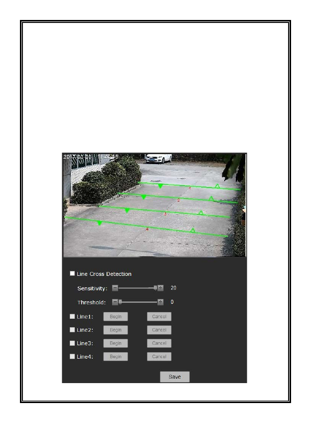
Figure 4-49 Line Cross Detection

62
The camera supports line cross detection. This allows the placement of four
virtual lines on the scene, marking where the allowed and prohibited entry
direction is. These are set using the mouse. When people or objects cross a line
in the wrong direction, an alarm is triggered.
Note: Enable the VCA functions in the Live view page () before setting
the line cross detection function (refer to Section 4.1).
From the Settings page, select Line Cross. Check Line Cross Detection to enable
the function. If a line has been placed, a green line with two direction arrows
appears on the screen. The solid arrow indicates the prohibited direction while
the hollow arrow indicates the allowed direction.
Draw a virtual line:
To draw a virtual line, select Line 1. Click the Begin button with the mouse, place
a start point on the screen, move the mouse and place an end point on the screen.
Then click the direction arrows on the line to set it solid or hollow.
When finished, click the End button. To edit a line, click the green line until it
turns blue with red endpoints. Then click the endpoints and move the mouse to
edit the line.
To redraw the line, click the Cancel button and draw it again.
When finished, click the “Save” button to save the line.
Set the sensitivity and threshold of the line cross detection function.
When finished, click the “Save” button.
63
4.6.3 Intrusion Detection
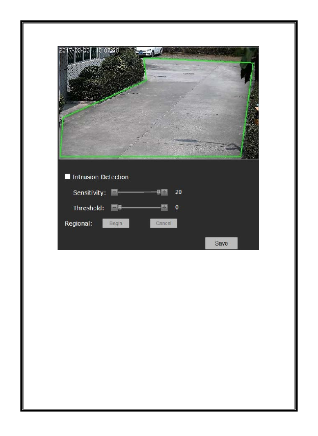
Figure 4-50 Intrusion Detection
The camera supports Intrusion Detection. One intrusion detection area can be
set. When objects move into this area, an alarm is triggered.
Check “Intrusion Detection” to enable the function. If an area has been set, a
green frame appears on the screen. If not, a default rectangle frame appears.

64
Draw an intrusion detection area:
Click the Begin button and then left-click the mouse on the video to draw the
first point; move the mouse and left click to draw the second point, and so on.
Up to eight points can be drawn. When the last point is drawn, move the mouse
to the first point. When a small red box appears, click to display a green closed
area.
Note: Up to eight points are allowed. After the last point is drawn, a green area
from the first point to the last point appears automatically.
When the area is finished, click the End button. To edit the area, click the green
frame of the area. When the frame turns blue from green, click the points and
move the mouse to change the area.
To redraw the area, click the Cancel button and draw it again.
When finished, click the “Save” button to save the area.
The sensitivity and threshold of the Intrusion Detection function can also be set.
4.6.4 Reset
From this interface, restore all the camera parameters to the factory default
settings.
4.7 Alarm Settings
Click “Alarm” in the left navigation bar to display the following Alarm Settings
interface:
65
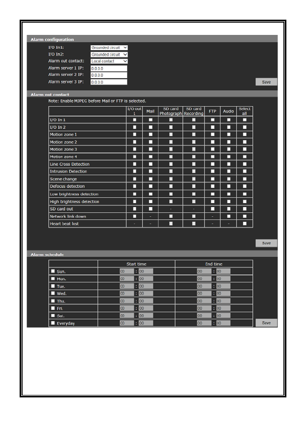
Figure 4-51 Alarm Settings
Alarm Configuration
The camera supports 2 alarm inputs, I/O in 1 and I/O in 2 and 1 alarm output, I/O
out. Users can set the status of each alarm input: Grounded Circuit or Open

66
Circuit. Grounded Circuit: “0;” Open Circuit: “1.”
Alarm out Contact: Set the transfer mode of the alarm signal, Local contact or
Net contact.
Local Contact: I/O out is triggered by I/O alarm in, motion detection alarm, video
contents analysis, TF card out, network link down or heart beat lost. Default:
Local Contact.
When the value of I/O out 1 is “1,” the switch status will be on.
When the value of I/O out 1 is “0,” the switch status will be off.
Net Contact: I/O out is controlled by the surveillance management software.
Note: This function can work with some Digital Video Surveillance
Management software. If Net contact is selected, users must set the IP of the
Alarm server as the server IP of the system. After the necessary settings in
software, users can control the relay switches remotely via the software. For
detailed information, refer to the Digital Video Surveillance Management
Software Operation manual.
Alarm Server IP: Set the IP address of alarm server. When an alarm occurs, the
alarm server is notified.
Alarm out Contact
Users can set the responding action for each switch signal I/O alarm in, motion
detection alarm, video contents analysis, TF card out, network link down or IP
address conflict from the options: Alarm out 1 (if Net Contact is selected, this
option is unavailable), TF card, Mail, FTP or Audio. When setting is completed,
click “Save” button.
Note: When “FTP” or “Mail” is selected, FTP or SMTP parameters must be set
in Network Settings; refer to Section 4.3.2 or Section 4.3.3 for details.
67
Alarm Schedule
The effective alarm schedule can be set. Users can select the alarm period. For
example, if Sunday is selected, on each Sunday the alarm will be in effect in the
set time; if Everyday is selected, alarm will be in effect in the set time every day.
The start time and end time is set up in the 24-hour format. The end time must be
after the start time. Press the “Save” button to activate the settings.
4.8 Storage Management
The camera supports storage with TF card. Click the Storage button to display
the Storage Management interface to set the recording parameters, replay and
download the recorded videos.
4.8.1 Storage Settings for Recording
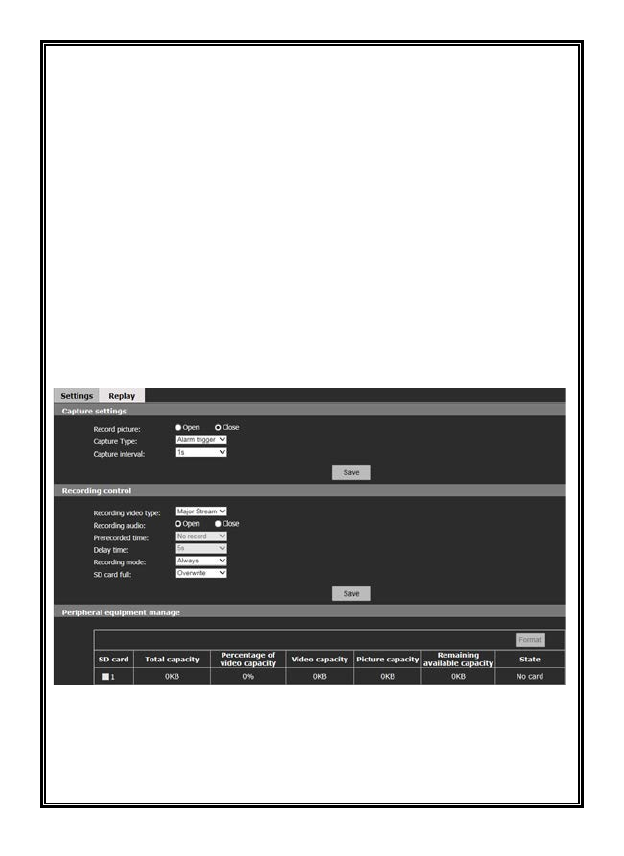
Figure 4-52 Storage Settings
Capture Settings:
Record picture: Open or close picture record.
Capture Type: Alarm trigger
68
Capture interval: Set the capture interval (in seconds).
Recording control:
Recording video type: Select the type of videos to record, major stream or minor
stream.
Recording audio: Open or close audio recording.
Prerecorded time: Select prerecord time in seconds, No record or No limit.
Delay time: Select delay time from 5s up to 10 minutes.
Recording mode: Set the recording mode; choose from Alarm triggered, Always
or Close options. When Alarm triggered is selected, and the setting of alarm
associated with TF card is set in the alarm interface (refer to section 4.7), when
the alarm occurs, recording is triggered automatically.
SD card full: Select what happens when the SD card is full from Overwrite or
Stop options. In Overwrite mode, when the TF card is full, the newly recorded
videos automatically overwrite the old videos; in Stop mode, when the TF card
is full, recording stop automatically.
Peripheral equipment:
View the total size, used space and state of TF card and also format it.
4.8.2 Replay
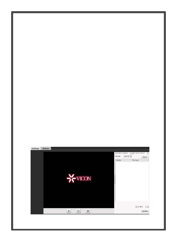
Figure 4-53 Replaying

69
Video Search: Set the start and end times at the top right and then click the Search
button. The recordings during this period of time will be listed.
Replay: To replay a video, double click the recording file in the list or select a
file and then press the “Play” button . During playback, click or to
pause or stop the playback.
Click the button on the right of video window to collapse the right window
and view the video full screen. Click the button to return to the page as Figure
4-53.
Download: The videos stored in the TF card can be downloaded to a local PC.
Select the file from the video list (multiple files can be selected simultaneously
using the “Ctrl” or “Shift” key) and then click the “Download” button to enter
the downloading interface.
Save to: Set the path to save the downloaded files. The default local storage
path is displayed. If a different location is required, click the “Browse” button.
AVI/H.264 drop-down list box: Select the downloaded file format.
In the download list, file total size, status and download progress will display.
Click the “Start” button and the files in the list will be downloaded in order.
The progress shows 100% when downloading is finished.
Click the “Open” button to enter download content.
4.9 Users Settings
The default admin user is ADMIN (uppercase; password: 1234). The admin can
add or delete other users and change their passwords. The user name ADMIN
cannot be changed but it is recommended to change the ADMIN password for
increased security. A maximum of 7 users are supported.
Detailed instructions on how to add and delete users are addressed below.
Click the Users option tab in the Settings interface; the following user
information will display. The “Num” item shows the number of the user and then
70
the user name. The “Property” column shows the authority of the user. In the
“Operation” column, use to delete and to edit user information. See
figure below:
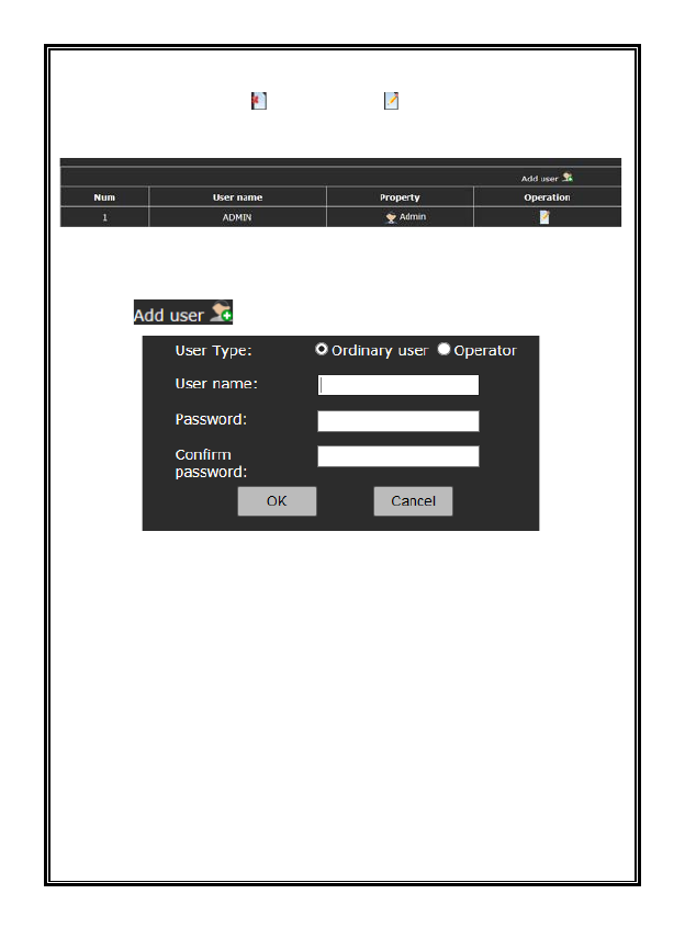
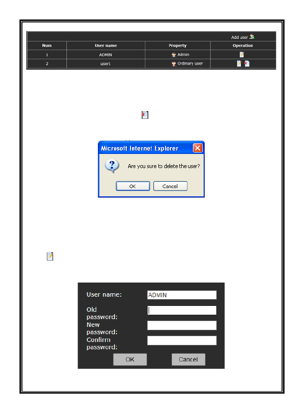
Figure 4-54 User Settings
1. Add Users
(1) Click “ ”to open the “Add a User” interface.
Figure 4-55 Add a User
(2) Enter the desired User Name and Password (user name and password can
include letters, numbers and underline only. No special characters are allowed.
The string length of user name can be between 1 and 30 characters and that of
the password is between 5 and 20 characters).
For the User Type, select Ordinary user or Operator. An ordinary user can view
videos and an Operator can view videos and configure video settings.
(3) Click “OK” button. If the setting is successful, the new user name will appear
in the account list, like new user “user1” in the example below:
71
Figure 4-56
2. Delete Users
In the “User setting” interface, click button under “Operation” for the user to
be deleted. The following dialog box will display:
Figure 4-57
Click “OK” button; the selected user will be deleted and the user list is
automatically updated.
3. User Password Change
Click button in the user list and the Edit User Information dialog box pops
up:
Figure 4-58
72
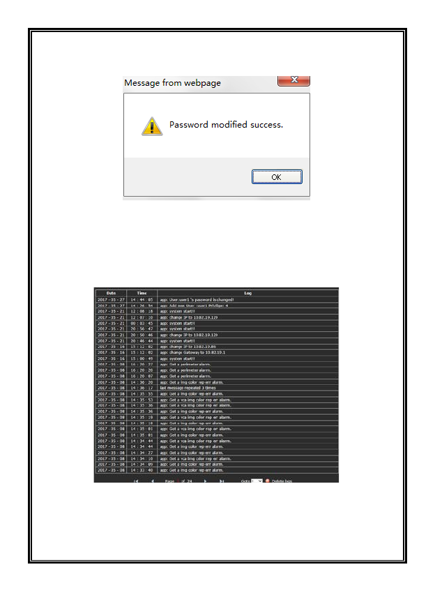
Input the old password, enter the desired new password (twice, once to confirm)
and then click “OK” button; the following popup will display; click OK:
Figure 4-59
4.10 System Log
Click the “Log” option tab to enter the system log interface. The date, time and
log information will appear on the screen.
Figure 4-60
Up to 30 logs can display on a page. The user can turn over the page by clicking
the arrows at the bottom or skip to a designated page by clicking Goto. To remove
a log, click “Delete logs;” a prompt will display. Click “Yes” to clear logs.

73
APPENDIX I QUESTIONS & SOLUTIONS
The following table describes the symptoms, causes and solutions for the
problems.
Symptoms
Possible Causes
Solutions
The network
camera does
not perform
initiation after
power-on
Wrong power connection
Reconnect power cable
Power supply failure
Repair or replace power
supply
Immediate startup after
power-off
Restart 10 seconds later
after power-off
If PoE power supply is used,
too long transmission distance
may make the power of the
Power Supply Switcher
insufficient.
Shorten the length of the
power supply network
cable or replace Power
Supply Switcher with more
power
If PoE power supply is used,
connection to other electric
appliance makes the ground
level not in correct level.
Disconnect
other electrical
appliances
No video signal
displayed
The plug-in for viewing image
is installed incorrectly.
Refer to the plug-in
installation to reinstall it
Network camera’s IP address
conflicts with other user’s IP
address
Set a unique IP address
Vague image Manual focus is not precise
Carefully manually adjust
the camera focus
Shipping Instructions
Use the following procedure when returning a unit to the factory:
1. Call or write Vicon for a Return Authorization (R.A.) at one of the locations listed below. Record
the name of the Vicon employee who issued the R.A.
Vicon Industries Inc.
135 Fell Court
Hauppauge, NY 11788
Phone: 631-952-2288; Toll-Free: 1-800-645-9116; Fax: 631-951-2288
For service or returns from countries in Europe, contact:
Vicon Industries Ltd
Unit 4, Nelson Industrial Park,
Hedge End, Southampton
SO30 2JH, United Kingdom
Phone: +44 (0)1489/566300; Fax: +44 (0)1489/566322
2. Attach a sheet of paper to the unit with the following information:
a. Name and address of the company returning the unit
b. Name of the Vicon employee who issued the R.A.
c. R. A. number
d. Brief description of the installation
e. Complete description of the problem and circumstances under which it occurs
f. Unit’s original date of purchase, if still under warranty
3. Pack the unit carefully. Use the original shipping carton or its equivalent for maximum
protection.
4. Mark the R.A. number on the outside of the carton on the shipping label.
Vicon Standard Equipment Warranty
Vicon Industries Inc. (the “Company”) warrants your equipment to be free from defects in material and
workmanship under Normal Use from the date of original retail purchase for a period of three years, with the
following exceptions:
1. All IQEYE Cameras: Two years if purchased before 1/1/2011.
2. Alliance-mini (IQD3xx), Alliance-mx (IQMxxx) and 3 Series (IQ03xx): Five years if purchased
between 1/2/2011 – 12/31/2014.
3. Alliance-Pro (IQA3xx): Five years if purchased between 3/2/2012 – 12/31/2014. Three years if the
motorized lens (IQA3xx-A3) option.
4. Access Control System Components: Two year from date of original retail purchase.
5. Uninterruptible Power Supplies: Two years from date of original retail purchase.
6. VDR-700 Recorder Series: One year from date of original retail purchase.
7. V5616MUX: One year from date of original retail purchase.
8. Arecont Cameras: One year from date of original retail purchase.
9. FMC series fiber-optic media converters and associated accessories: Lifetime warranty.
10. For PTZ cameras, “Normal Use” excludes prolonged use of lens and pan-and-tilt motors, gear
heads, and gears due to continuous use of “autopan” or “tour” modes of operation. Such
continuous operation is outside the scope of this warranty.
11. Any product sold as “special” or not listed in Vicon’s commercial price list: One year from date of
original retail purchase.
NOTE:
• If the product is to be used outdoors or in dusty, humid, or other hostile environments, it must be
suitably protected.
• Camera products must be protected, whether in use or not, from exposure to direct sunlight or
halogen light as the light may damage the camera image sensor. This applies to both indoor and
outdoor use of the cameras.
• For camera products supplied without a lens, extreme care should be used when mounting a lens
on these products. Damage to the product due to incorrectly mounted lenses will invalidate this
limited hardware warranty.
• Failure to comply with any of the aforementioned requirements will invalidate this Limited Hardware
Warranty.
Date of retail purchase is the date original end-user takes possession of the equipment, or, at the sole
discretion of the Company, the date the equipment first becomes operational by the original end-user.
The sole remedy under this Warranty is that defective equipment be repaired or (at the Company’s option)
replaced, at Company repair centers, provided the equipment has been authorized for return by the Company,
and the return shipment is prepaid in accordance with policy. Repaired or replacement hardware will be
warranted for the remainder of the original Warranty Period or ninety (90) days, whichever is longer. When a
product or part is exchanged the replacement hardware becomes the property of the original purchaser and
all hardware or part thereof that is replaced shall become the property of Vicon.
The warranty does not apply (a) to faulty and improper installation, maintenance, service, repair and/or
alteration in any way that is not contemplated in the documentation for the product or carried out with Vicon
consent in writing, operation adjustments covered in the operating manual for the product or normal
maintenance, (b) to cosmetic damages, (c) if the product is modified or tampered with, (d) if the product is
damaged by acts of God, misuse, abuse, negligence, accident, normal wear and tear and deterioration,
improper environmental conditions (including, but not limited to, electrical surges, water damage, chemical
exposure, an/or heat/cold exposure) or lack of responsible care, (e) if the product has had the model or serial
number altered, defaced or removed, (f) to consumables (such as storage media or batteries) (g) to products
that have been purchased “as is” and Vicon the seller or the liquidator expressly disclaim their warranty
obligation pertaining to the product, (h) to any non-Vicon hardware product or any software (irrespective of
packaged or sold with Vicon hardware product) and Vicon products purchased from an unauthorized
distributor/reseller, (i) to damage that occurs in shipment or (j) to damages by any other causes not related to
defective design, workmanship and/or materials.
The warranty for the products shall run from Vicon to End User customers only (including product purchased
through authorized partners and resellers). Vicon is not obligated under any circumstances to honor warranties
on product(s) purchases from internet auction sites including eBay, uBid or from any other unauthorized
resellers. Except as explicitly provided herein, Vicon disclaims all other warranties, including the implied
warranties of fitness for a particular purpose and merchantability.
Software supplied either separately or in hardware is furnished on an “As Is” basis. Vicon does not
warrant that such software shall be error (bug) free. Software support via telephone, if provided at no
cost, may be discontinued at any time without notice at Vicon’s sole discretion. Vicon reserves the
right to make changes to its software in any of its products at any time and without notice.
The Warranty and remedies provided above are exclusive and in lieu of all other express or implied
warranties including, but not limited to, the implied warranties of merchantability or fitness for a
particular purpose. Certain jurisdictions do not allow the exclusion of implied warranties. If laws under
such jurisdictions apply, then all express and implied warranties are limited to the warranty period
identified above. Unless provided herein, any statements or representations made by any other
person or firm are void. Except as provided in this written warranty and to the extent permitted by law,
neither Vicon nor any affiliated shall be liable for any loss, (including loss of data and information),
inconvenience, or damage, including, but not limited to, direct, special, incidental or consequential
damages, resulting from the use or inability to use the Vicon product, whether resulting from breach
of warranty or any other legal theory. Notwithstanding the foregoing, Vicon total liability for all claims
under this warranty shall not exceed the price paid for the product. These limitations on potential
liabilities have been an essential condition in setting the product.
No one is authorized to assume any liability on behalf of the Company, or impose any obligations on it in
connection with the sale of any Goods, other than that which is specified above. In no event will the Company
be liable for indirect, special, incidental, consequential, or other damages, whether arising from interrupted
equipment operation, loss of data, replacement of equipment or software, costs or repairs undertaken by the
Purchaser, or other causes.
This warranty applies to all sales made by the Company or its dealers and shall be governed by the laws of
New York State without regard to its conflict of laws principles. This Warranty shall be enforceable against the
Company only in the courts located in the State of New York.
The form of this Warranty is effective August 1, 2015.
THE TERMS OF THIS WARRANTY APPLY ONLY TO SALES MADE WHILE THIS WARRANTY IS IN
EFFECT. THIS WARRANTY SHALL BE OF NO EFFECT IF AT THE TIME OF SALE A DIFFERENT
WARRANTY IS POSTED ON THE COMPANY’S WEBSITE, WWW.VICON-SECURITY.COM. IN THAT
EVENT, THE TERMS OF THE POSTED WARRANTY SHALL APPLY EXCLUSIVELY.
Vicon Part Number: 8006-9010-03-12 Rev 0815