Sega Genesis F Mdrive User Guide FM DRIVE TECH MANUAL
Genesis F-Mdrive - User Guide genesis_fmdrive_ug_en Free User Guide for Sega Console, Manual
2015-07-27
: Sega Sega-Genesis-F-Mdrive-User-Guide-779087 sega-genesis-f-mdrive-user-guide-779087 sega pdf
Open the PDF directly: View PDF ![]() .
.
Page Count: 55
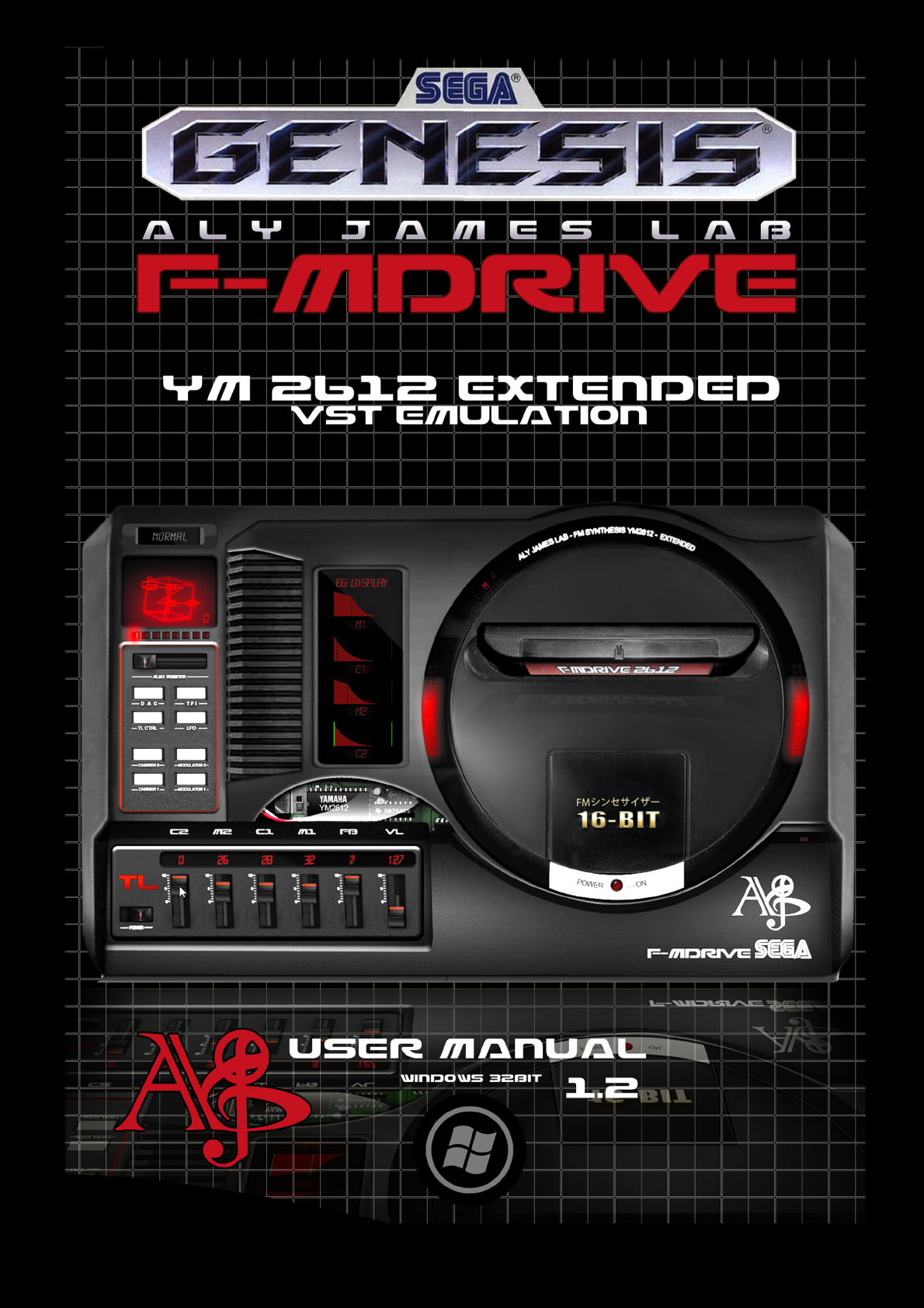

FM-DRIVE 2612 VST
USER MANUAL 1.2
BY
Aly James
©2013 ALYJAMESLAB

Table of Contents
FM-DRIVE 2612 VST ...................................................................................................................... 1
INTRODUCTION............................................................................................................................. 3
INSTALLATION............................................................................................................................... 6
CONTROL PANELS ......................................................................................................................... 9
THE YAMAHA YM2612 FM CHIP ....................................................................................................11
OPERATOR CORE..........................................................................................................................12
ENVELOPE GENERATORS ..............................................................................................................14
ALGORITHMS ...............................................................................................................................20
LFO .............................................................................................................................................23
SOUND MODELS ..........................................................................................................................25
NORMAL/SPECIAL MODE ..............................................................................................................30
CSM MODE ..................................................................................................................................32
D.A.C ...........................................................................................................................................35
TFI IMPORT / EXPORT ...................................................................................................................37
CIRCUIT BENDING ........................................................................................................................40
MIDI AUTOMATION......................................................................................................................41
GENMDM ....................................................................................................................................42
PARAMETERS LIST ........................................................................................................................43
FM SYNTHESIS .............................................................................................................................46
APPENDIX ....................................................................................................................................47
LINKS...........................................................................................................................................52
DISCLAIMER & LICENCE AGREEMENT ............................................................................................54
INTRODUCTION
My name is Aly James;
French steam funky musician, composer and creator of strange musical DIY devices and software.
Normally I am more inclined to make some guitar & bass oriented devices but I am also a fan of the
SEGA GENESIS/MEGADRIVE sound, it was my first console and it opens up my imagination and lot.
I was not very used to tracker music making or MML programming, which is why I needed an
YM2612 Vst Instrument, for personal use. Also I needed a way to control the real hardware via MIDI.
I learn a lot from documentations and hardware tests and from all the nice people who documented
the YM2612 on the web. You know who you are.
It turns out to be quite nice so I decided to make it public in exchange for a small donation for the
large amount of work I put into this.
This emulation uses a totally new core that I started from scratch a few months ago and was almost
fine-tuned by ear so minors differences with the hardware could appears sometimes.
The goal was on one hand to reproduce the hardware distortion “ladder effect” of the Sega
Megadrive model 1 and the features of the YM2612 chip and on the other hand to expand further
the original capabilities and create a high resolution processing mode for perfect sound quality.
I needed a toy to have best of both world and an inspiring FM synth.
I tested the not well known CSM "illegal mode" usage, designing custom ROMS to investigate further
and finally include a way in FMDRIVE 2612 to use CSM for modern music production.
All and all the SEGA MEGADRIVE EXTENDED emulation turns out to be a fantastic FM synth suitable
for chip music and Sega nostalgic pleasure and also a powerful tool for modern music production.
The product has been crafted through the SYNTHEDIT engine using the very last version, custom C++
coding and third party licensed code. It may be ported to OSX at some point in the future.
Thanks to all the nice people that started to use FMDrive and support my projects.
A special thanks to Sebastian Tomczak who designed the GENMDM midi hardware interface and
provide great sources of inspiration and to Yuzo Koshiro for his FM music and support on FMDrive.
Credits can be accessed on the FMDrive GUI panel.

Mainly,
FMDRIVE can act either as the YM2612 CH1, 2, 3(with special mode or CSM) 4, 5 or 6 (FM or
DAC).
It can be either polyphonic (up to 6 voices) or mono like the real chip and can act as 6
YM2612 channels at once with the same patch when in poly mode...
However you have to load 6 instances of the VST to have the YM2612 six channels original
setup.
This particular implementation allows getting over the original six channels limit if ones need
it.
Like 15 instances of FMDrive for example for a massive FM wall of sound!
However you can still have a lot of control on only one instance, as everything can be MIDI
automated in a DAW, you can have a maximum of control over the chip, for example you
can change the algorithm and others registers via MIDI CC on the same instance and same
MIDI track. Every registers can be automated or recorded via the GUI and his will change the
sound.
Basic MIDI implementation:
MIDI IN:
FMDrive receive MIDI CH1 as main source for notes and key on/off.
However when in SPECIAL MODE FMDrive can optionally receive
MIDI CH 11, 12, 13 to control operators key on/off and frequency separately and MIDI CH 14
to control CSM timer period by note (this is explained in detail later).
MIDI OUT:
FMDrive can send MIDI CC data over any MIDI channels.
For example if you assign MIDI CC#15 to the LFO speed register, when it is changed, FMDrive
will also send CC#15 DATA over the chosen MIDI Channel allowing to control another
instance of FMDrive or another Vsti.
Imagine that on another FMDrive instance you assign the same MIDI CC#15 to the Frequency
of an operator in SPECIAL MODE…Then, when the LFO change on the first instance, the
second instance will change the Frequency of the operator following the LFO speed change!
Now imagine what it is capable of…

INSTALLATION
COMPATIBILITY
FMDRIVE is a Windows 32Bit VST Instrument for use with MIDI capable DAWs.
RUN on 32/64 Bit Systems.
If you want to use it with a 64bit DAW you can use JBridge.
INSTALL VST
1. Decompress the downloaded archive file
2. Copy the entire Folder AJLAB to your VST PLUGINS folder
3. Load it in your DAW
INSTALL STANDALONE
1. Decompress the downloaded archive file
2. Copy the entire Folder FMDRIVE where you want
3. Simply RUN FMDRIVE.exe
State of FMDRIVE 2612 current
features
WIN 32 VST runs on 32/64Bit Systems and it is multicore compatible
HIGH QUALITY GUI
(Different panels for controls etc...)
INSTANT UPDATE FOR ALL CONTROLS
FULL MIDI AUTOMATION
With midi learn (right click to assign MIDI)
POLY & MONO MODE with Glide Control
DIRECT OUTPUT OR MD1 Headphone Out filtering
TWO AUDIO MODELS: HQ and MD1
(Crystal clear and high resolution processing) and MD1 (emulate distortion and low resolution of
MD1 model)
YM2612 classic features
4 OP FM SYNTHESIS
PARAMETRIC Envelope Generator
SSG EG
LFO AM & PM
CH3 SPECIAL MODE
(Different frequencies for each OP) also different key on off by External Midi channels
CSM MODE
(Kind of early vocal synthesis)
CH6 DAC MODE
(4 slots to load any PCM WAV files/ auto converted to mono 8/4bit 22/11/8Khz) with selectable
start/end points, loop and pitch control.
YM2612 extended switchable features
OVERDRIVE LADDER EFFECT CONTROL
(Works only in MD1 MODE, adjust to taste)
RATE RATIO CONTROL
(Change the global EG RATE/SPEED from *0.1 to *4 for rapid tweaking/adjustment of the envelopes)
GRAPHIC EG
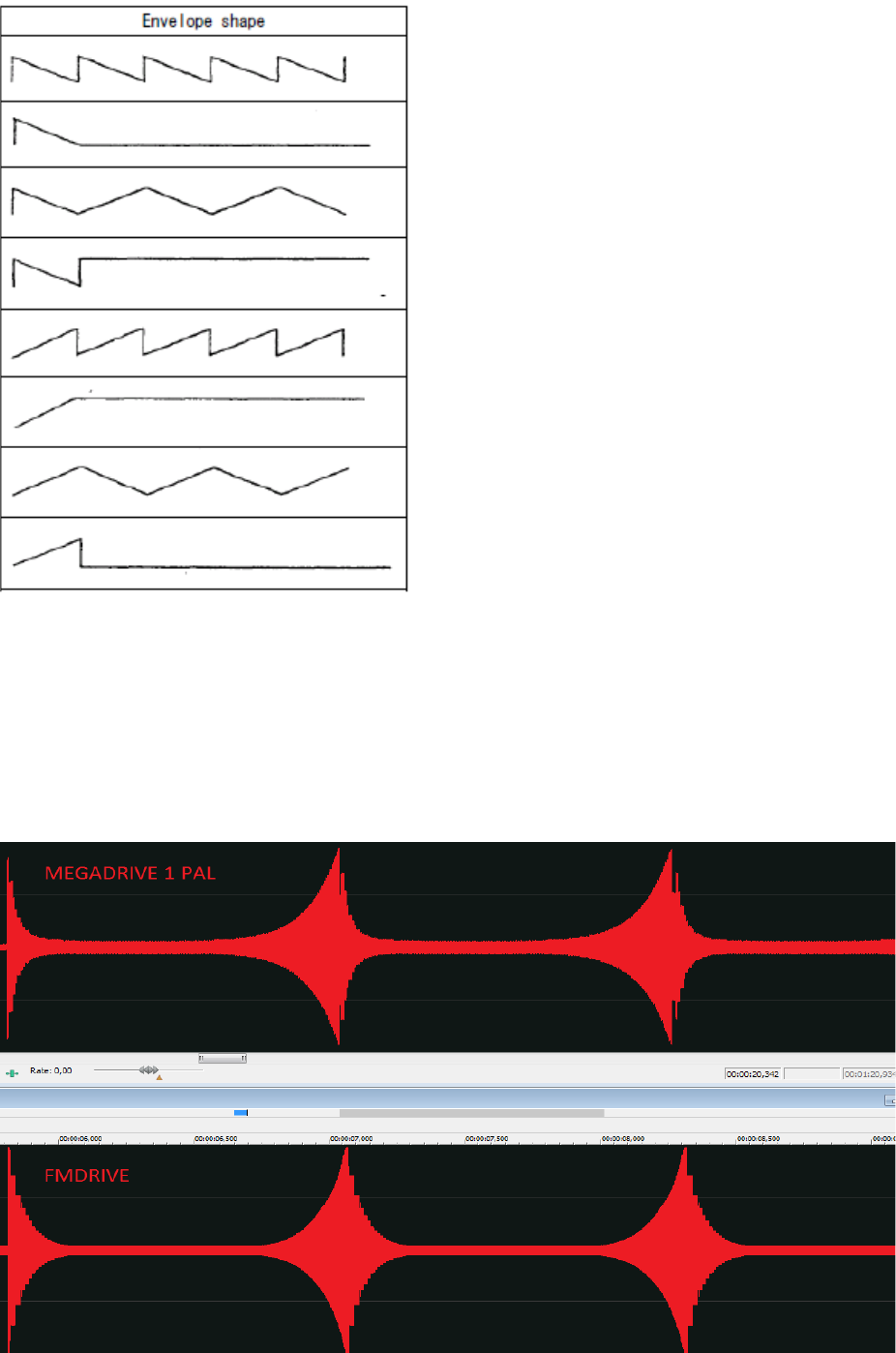
Up to 8 stages /8 stage shapes/custom loop poi nt (aka custom SSG) and sustain point.
CUSTOM LFO RATE (for low modulation...)
6 LFO SHAPE
Including noise
ATTACK & RELEASE Time for the LFO
DT2 PARAMETER from YM2151
UNSYNC PMS
(Different settings for each OP)
OP FILTER aka PHASE MODULATION FILTERING
(Reduce the modulation at high frequencies according to the amount of filtering)
GLOBAL FM SAMPLE RATE CONTROL
(Skip audio samples)
POLYPHONIC REDUCER
(Kind of increasing the FM bit crushing audio effect according to the number of voice/keys played..)
DAC CUSTOM GRAPHIC WAVEFORM (14 bytes)
DRAW MODE or LFSR
(Random bytes generated, clock divider, sync with host tempo)
CSM Timer A Control by MIDI notes
(Shortest period limit is 1.13636ms note A5)
LOADS & SAVE TFI PATCHES
(Manual or auto load for fast selection)
LOAD & SAVE FULL PATCH & BANKS in FXB/FXP
CONTROLS THE REAL MEGADRIVE HARDWARE VIA MIDI
(Needed Little Scale GENMDM Midi Device)
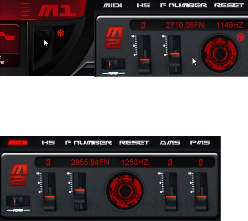
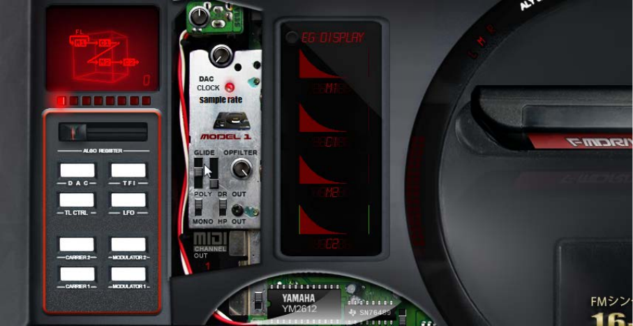
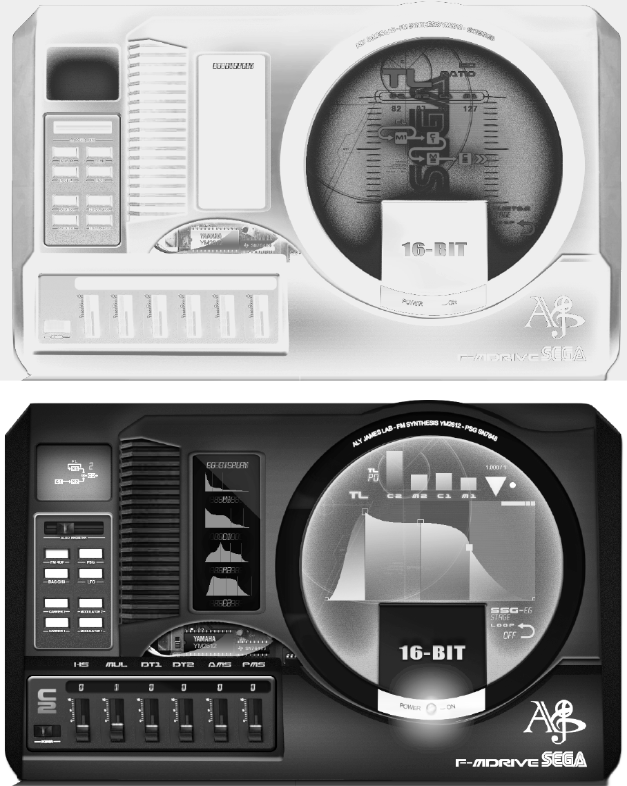
CONTROL PANELS
FMDRIVE GUI INTERFACE stores the different parameters on different panels
The central visual interface can be opened or closed clicking on the led next to power on.
These are:
1 VU METER (only when the central panel is closed)
1 TL panel (allows control over each operator volume, M1 feedback, global velocity sensitivity,
velocity enable for each operator and number of polyphonic voices, fixed frequencies for SPECIAL
MODE and Model1 Overdrive Ladder effect level)
4 Operators panels (one for each operator, access via left white buttons or clicking on the operator
name on the envelope generators display)
1 DAC panel (with one sub panel for the DAC custom waveform)
1 LFO panel
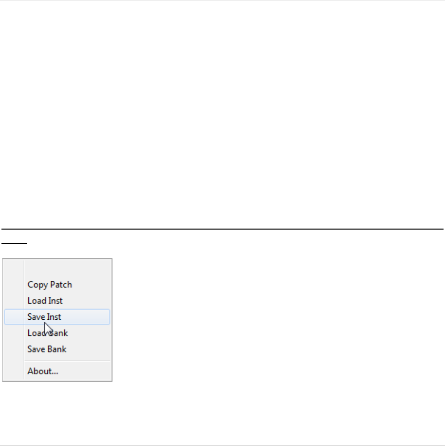
1 TFI control panel for loading and saving (allows browsing for tfi patches via internal browser or
windows explorer)
1 Tweak control panel (for circuit bending and additional control)
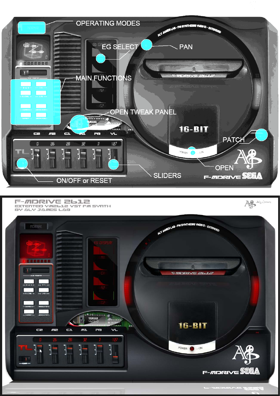
Right click on a knob, button or slider will open a midi learn assign menu. Ctrl click + move allow fine
tuning.
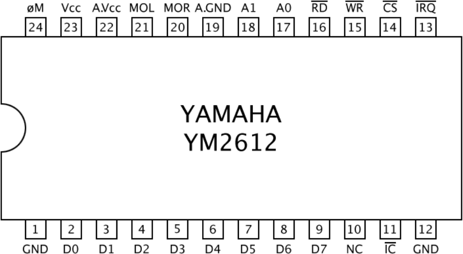
THE YAMAHA YM2612
FM CHIP
The YM2612, aka OPN2, is a six-channel sound chip developed by Yamaha. It belongs to Yamaha's
OPN family of FM synthesis chips used in several game and computer systems.
It was most notably used in the Sega Mega Drive/Sega Genesis game console.
The YM2612 has the following features:
• Six concurrent FM Channel (Voice)
• Four operators per channel
• Two interval timers
• A sine-wave low frequency oscillator
• Analogue stereo output (most other contemporary Yamaha FM chips require a separate
external digital-to-analog converter chip)
• For channel three, operator frequencies can be set independently, making dissonant
harmonics possible. (Normally, they would have a simple relation relative to a common base
frequency.)
• For channel six 8Bit PCM samples can be played instead of FM sound
• Per-channel programmable stereo sound (Left, Right, or both Left and Right)
The particular implementation of the DAC produces some noticeable artifacts on the Sega Megadrive
sound output, similar to distortion, the sound can clip at high levels and the sine wave output start to
change at low volume, mixed with a squared signal.
The chip was also stripped of its predecessor’s (YM2608) SSG component, although its vestigial SSG
envelope generator is still functional.
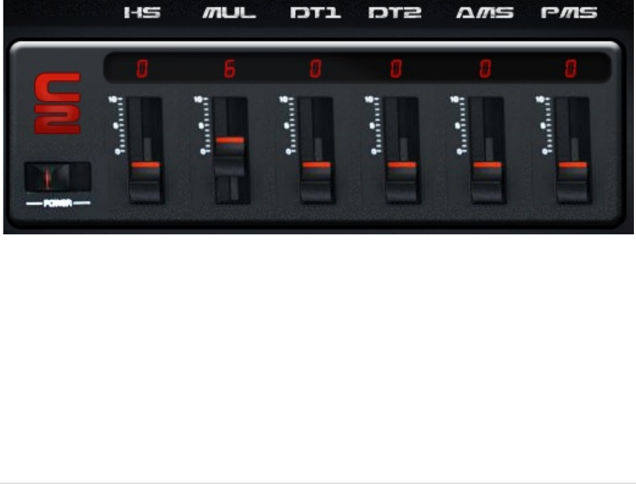
OPERATOR CORE
Each Operator is switchable Mask on/off to receive note on/off commands. Doing this also disable
the envelope generator saving system memory resources when not in use.
LIST OF PARAMETERS:
TL: Operator general volume (on MD1 Mode TL below 0X67 (104) will produce no audible output.
KS: Key Scaling/ change the timing of the EG according to the pitch of the notes, the higher the pitch
the shorter is the envelope. KS affects AR, DR, D2R and RR in the same way. KS is the degree to which
the envelope becomes narrower as the frequency becomes higher.
MUL: Frequency Multiplier/ *0.5 to *15 where 1 is the actual ROOT frequency, 0 is an octave below.
This follows harmonic relation to the root frequency.
DT1: Fine detune/ following this table (frequency is a small number) small detuning can create
movement on the sound.
DT1
0 1 2 3 4 5 6 7
FREQUENCY DETUNE
0 1 2 3 0 -1 -2 -3
DT2: Coarse detune/ Large frequency detune (modeled after YM2151 chip)
DT2
0 1 2 3
F-DETUNE HZ
0 19.4 21.58 23.77
AM: Enable LFO Amplitude Modulation (AMS) for that Operator. Relevant only if both the LFO is
enabled and AMS (amplitude modulation sensitivity) is non-zero.
PMS: Pitch Modulation Sensitivity
AM
EFFECT ON VOLUME
PMS
EFFECT ON PITCH
0
1
No effect
Enable AMS
0
1
2
3
4
5
6
7
No effect
Displacement of ± 3.4%*
Displacement of ± 6.7%*
Displacement of ± 10%*
Displacement of ± 14%*
Displacement of ± 20%*
Displacement of ± 40%*
Displacement of ± 80%*
* % of a halftone.
ENVELOPE
GENERATORS
PARAMETRIC ENVELOPES
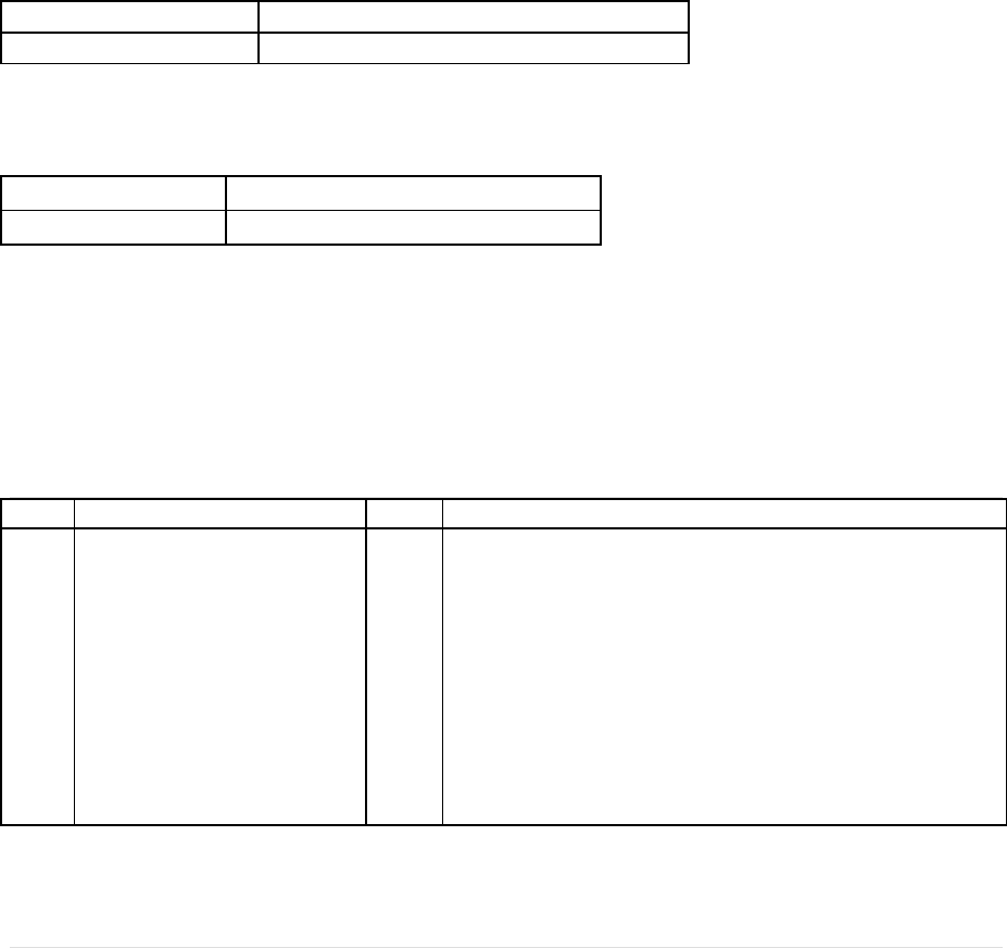
The typo used for naming the envelope stages varies with documentations, FMDRIVE uses:
AR, DR, SL, D2R and RR for Attack, First Decay, Sustain Level, Secondary Decay and Release.
The sound starts when the key is depressed, a process called ‘key on’. The sound has an attack, a
strong primary decay, followed by a slow secondary decay. The sound continues this secondary
decay until the key is released, a process called ‘key off’. The sound then begins a rapid final decay,
representing for example a piano note after the key has been released and the damper has come
down on the strings.
The envelope is represented by the above amplitudes and angles, and a few supplementary registers.
Used in the above diagram are:
TL
Total level, the highest amplitude of the waveform.
AR
Attack rate, the angle of initial amplitude increase. This can be made very steep if desired. The
problem with slow attack rates is that if the notes are short, the release (called ‘key off’) occurs
before the note has reached a reasonable level.
DR
The angle of initial amplitude decrease.
SL
The amplitude at which the slower amplitude decrease starts.
D2R
The angle of secondary amplitude decrease. This will continue indefinitely unless ‘key off’
occurs.
RR
The final angle of amplitude decrease, after ‘key off’.
IMPORTANT NOTE ON EG BEHAVIOR:
The Volume value is an ATTENUATION VALUE (ex TL = 127 means that the attenuation is MAX so
volume is = MIN, TL = 0 means that there is no attenuation so volume = MAX)
IF AR = 0, The YM2612 consider the Attack stage as Infinite, so no sound would be produced.
Setting AR to 0 in PARAMETRIC EG will also disable GRAPHIC EG output regardless of the graphic
settings.
IF DR = 0, DR stage is off and the Envelope switch directly to D2R stage, however if SL is non-zero
D2R will have no effect and the envelope will sustain at TL volume, whatever value SL is.
IF D2R = 0 = off, the envelope will sustain at SL volume.
USING HIGH Release Time (close to 0) is more CPU hungry in poly mode; avoid using high release
time when not needed.
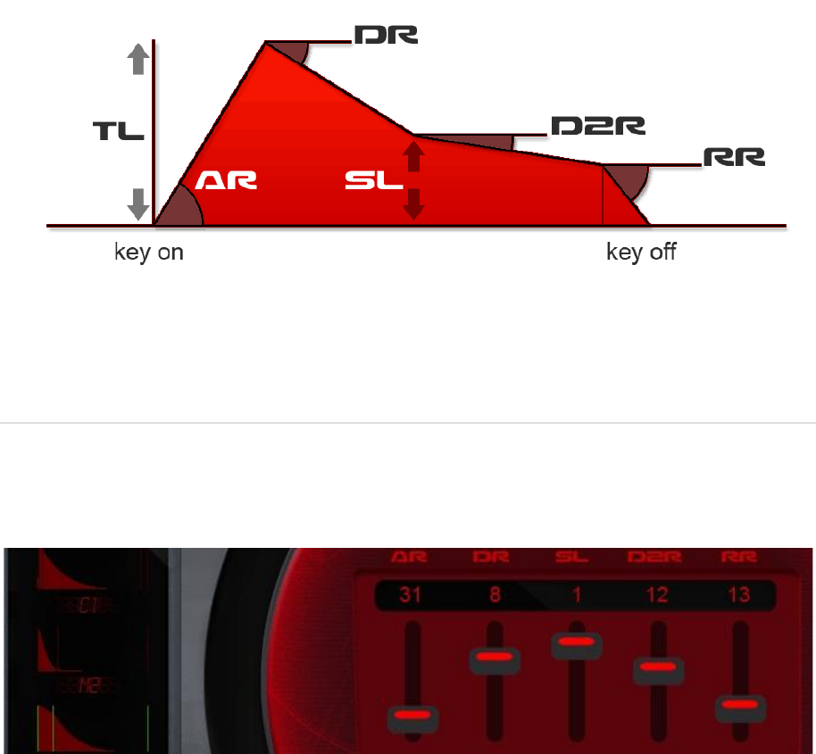
GRAPHIC representation of the envelope helps to understand the behavior. It can be changed with a
small knob at the top to a solid or a line view.
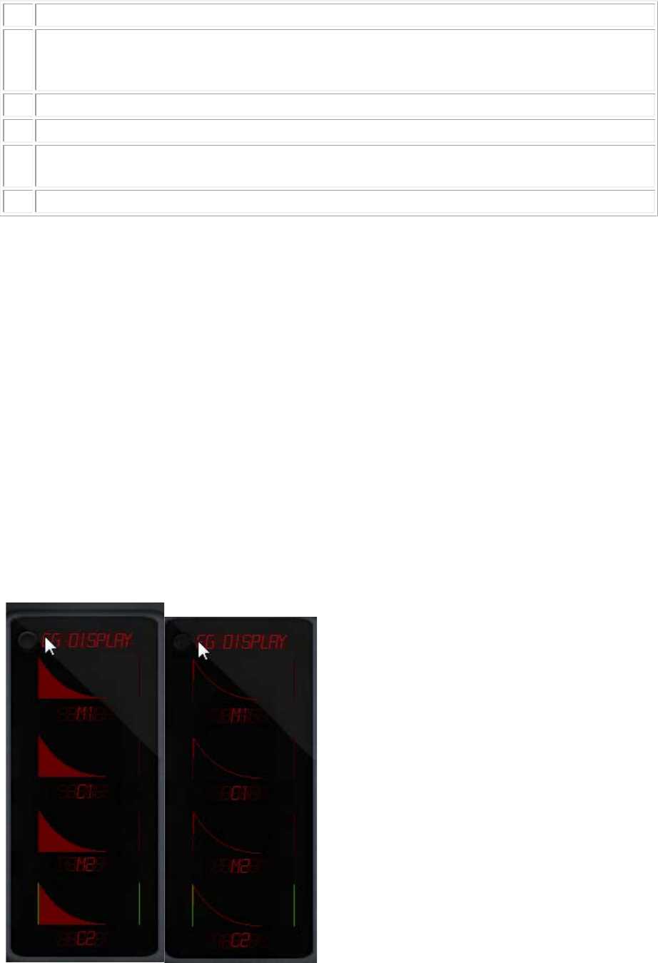
SSG ENVELOPES MODE
When activated SSG mode will loop the envelope from AR to D2R (included) following 8 defined
shapes and behavior. The envelope time is also shorter than normal and will never reach MIN volume
except when HELD. If an Attack stage is set, AR is > 31 or 30, the behavior of the SSG is changed.
(Graphic representation of the envelope on the SSG panel will show the effect.)
SSG envelopes are combination of these following behaviors:
NORMAL: the envelope plays normally
INV: The envelope is inverted
HELD: The envelope is held at Max attenuation value
INVERTED HELD: The envelope is held at Max volume
ALT: The envelope alternates between NORMAL & INV ant each pass
CLICK TO ACTIVATE AND CHANGE SSG SHAPES
The phase is also reset in SSG mode at the beginning of each repetition of the waveform in cases
where both the HLD and ALT bits are unset. This produces different harmonic results when the
envelope is very short.
SSG part comes from YM2608 and where not implemented for use with an attack phase on the Sega
Megadrive. When the Attack phase is inverted, this can creates an attack curve which makes several
extremely large audible steps from 0db
Technical manuals claim that AR should be 31 (no attack) when using SSG…however setting an attack
phase and producing this behavior can be used in a creative way.
Here is an example of SSG behavior with an attack phase AR of 8 and D2R of 10. SSG from 0 to 6
GRAPHIC ENVELOPES
Extended feature of FMDRIVE allows the use of custom complex envelopes instead of the original
parametric. (can be done on a real YM2612 by sending software envelope data to TL register)
Left Clicking on a stage will change the shape.
Left Click on the top of the graphic will open a POP UP MENU
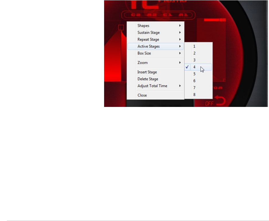
A click at the top of the graphic envelope opens a pop up menu allowing full control.
Zoom from 100% to 1000% and SHIFT/CTRL for fine & ultra-fine mouse control.
• GUI CONTROL (zoom, handle box size etc…)
• CHANGE STAGE SHAPE
• ADD OR REMOVE UP to 8 STAGES
• DEFINE CUSTOM LOOP POINT AND SUSTAIN POINT
• ADJUST GLOBAL TIME
POP UP MENU allows changing the global time using a percent of the actual time.
The Stage loop point can be defined on the GUI, also in the POP UP menu.
Each stage shape can be adjusted by the user by just left clicking on it.
The Release stage will include all stages after the sustain point.
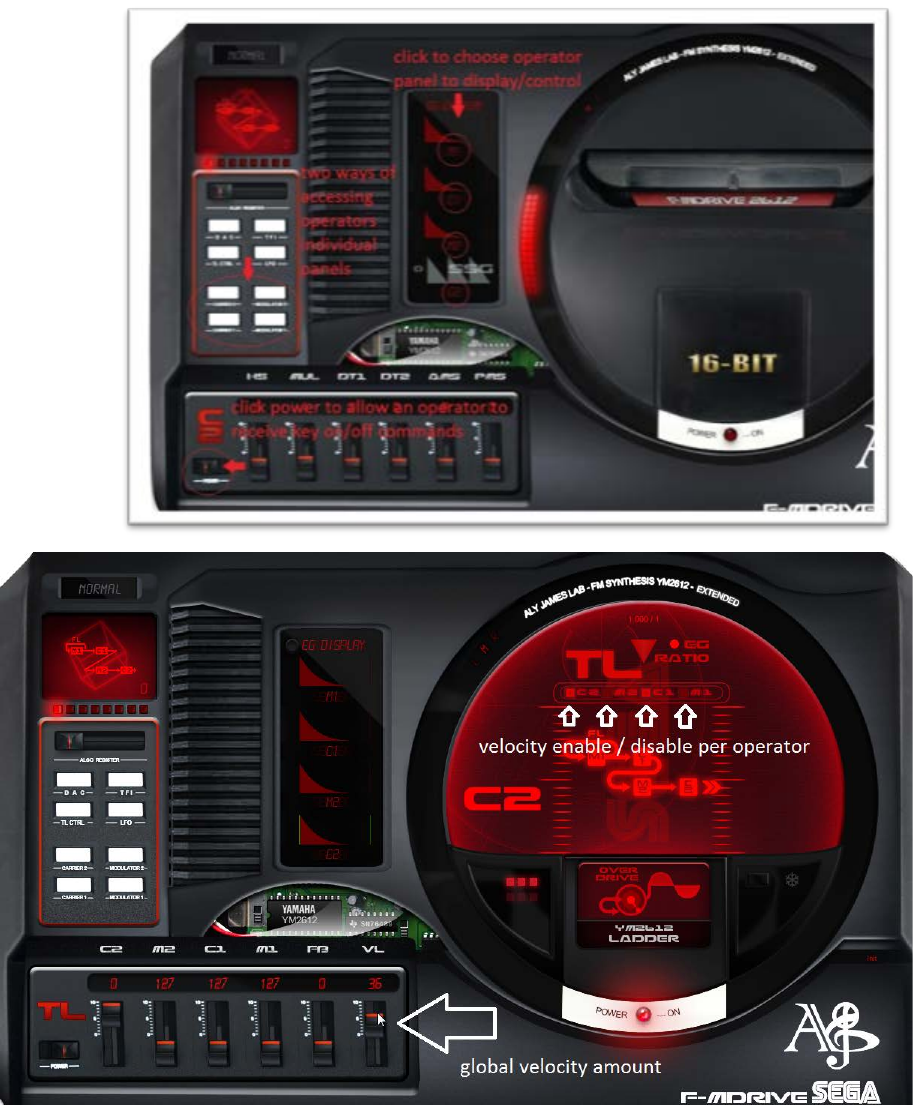
VELOCITY CONTROL
The VL slider on the TL CTRL panel will adjust the amount of velocity that will be applied to the
operators’ volume. The velocity max is the TL of the current operator.
A VL enable square button is available on the TL screen for each operator.
Velocity can add expressivity to the sound when used on Modulators.
GRAPHIC CONTROL
Initially YM2612 has 4 Stages EG.
With FM DRIVE, the user can add up
to 8 Stages to improve control.
Also the original SSG EG part was
fixed on the chip like shown on fig1.
With FM DRIVE, the user can control
the SSG part by selecting from witch
stage the loop occurs until it reaches
custom sustain stage point.
So you got complete control over a
custom SSG Mode.
RATE RATIO CONTROL
RATE RATIO CONTROL
Allows to change the global EG RATE/SPEED from *0.1 to *4 for rapid tweaking and adjustment
of the envelopes.
IT IS INVERTED when in PARAMETRIC MODE (*0.1 = *4 and *4=*0.1)
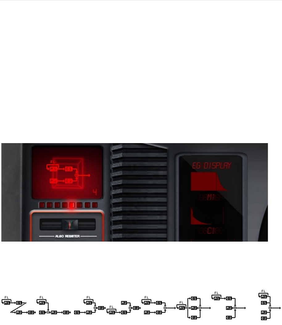
ALGORITHMS
There is 8 operator’s combination (connection status) available in the YM2612
Each slot works by the algorithm as a modulator or a carrier. However, the fourth slot (C2) is always
set to the carrier regardless of the algorithm. (Graphic representation is also available on TL panel)
The choice of algorithm is essential in the process of sound design; the following type of sounds can
be achieved depending on the choice.
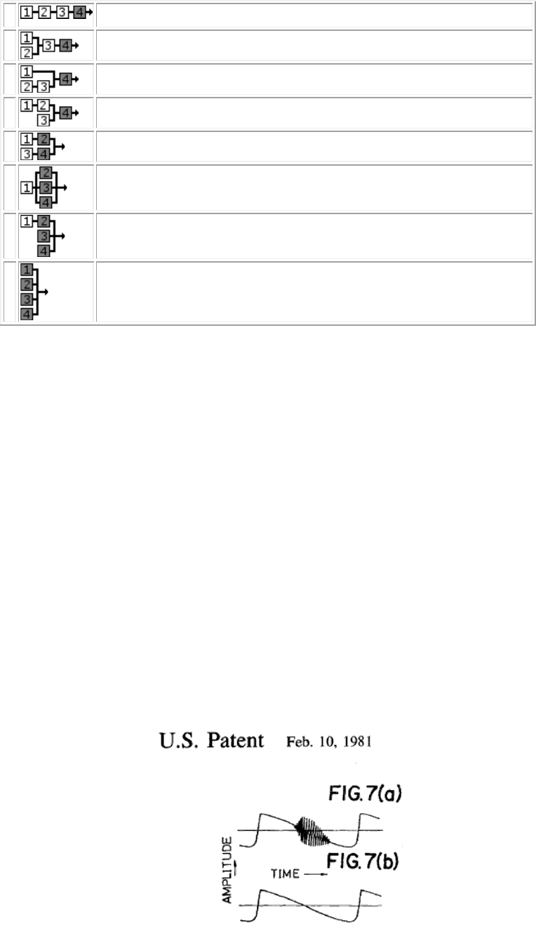
Some examples of sound types:
0
Distortion guitar, “high hat chopper” Bass…
1
Harp, PSG type sound…
2
Bass, electric guitar, brass, piano, woods …
3
String, folk guitar, chimes…
4
Flute, bells, chorus, bass drum, snare drum, tom-tom…
5
Brass, organ …
6
Xylophone, tom-tom, organ, vibraphone, snare drum, kick drum
7
Pipe organ, CSM speech…
The First SLOT, Operator M1 is capable of self-modulation called feedback. (FB)
Regarding this formula:
𝑦=𝑥+𝛽sin 𝑦
𝑥
𝑛
=sin(𝜋(𝜃+𝛽𝑥
𝑛−1
))
It is assumed that 𝑥𝑛 is the output of the oscillator, ϴ is the phase accumulator ranging from -1 to 1,
and β is the scaling function
The effect is slowly changing the sine wave into a saw tooth waveform then into noise.
Depending on the TL volume of M1 operator and the setting of FB the effect will be more or less
pronounced.
The feedback system is based on Tomisawa 1981 US patent “Tone production method for an
electronic musical instrument”
Note on filtering: Filtering the output is done internally.
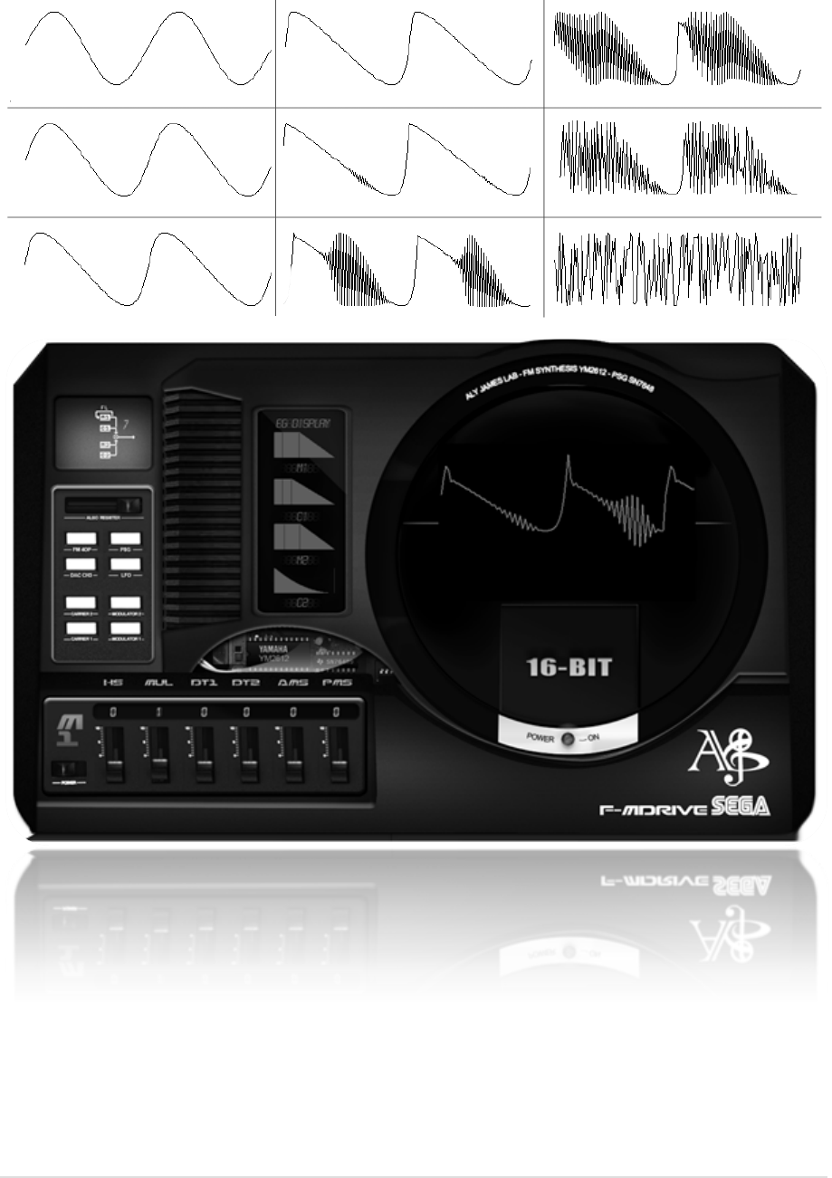
LFO
LFO can be used for tremolo type effect (AMS) or vibrato (PMS) both can be used for FX.
The LFO is a basic sine wave in the YM2612. Others types of wave could only be achieved by software
programing. FMDRIVE adds 5 classic waveforms.
List of parameters
FRQ: the frequency of the LFO/ ranges from 3.98Hz to 72.2Hz on the YM2612
CUSTOM FRQ MODE: Will set FRQ to an even more usable range kind of like YM2151 from 0,013Hz
to 53.49Hz.
The SONIC sprite will run according to the frequency.
AR: Attack rate, slowly increase AMS/PMS to the setting point. 127 = no attack
RR: Release rate starting on KEY OFF / Similar to AR
WF: 6 Waveforms/ SIN/SAW/RAMP/TRIANGLE/SQUARE/NOISE
AMS: Amplitude Amount of Modulation
AMS
EFFECT ON VOLUME
PMS
EFFECT ON PITCH
0
1
2
3
No effect
Displacement of 1.4 dB
Displacement of 5.9 dB
Displacement of 11.8 dB
0
1
2
3
4
5
6
7
No effect
Displacement of ± 3.4%+PMD
Displacement of ± 6.7%+PMD
Displacement of ± 10%+PMD
Displacement of ± 14%+PMD
Displacement of ± 20%+PMD
Displacement of ± 40%+PMD
Displacement of ± 80%+PMD
UNSYNC PMS: Disable the global PMS control and add a PMS parameter per Operator
PMD: Pitch Frequency Amount of modulation can increase the initial YM2612 limit of PMS
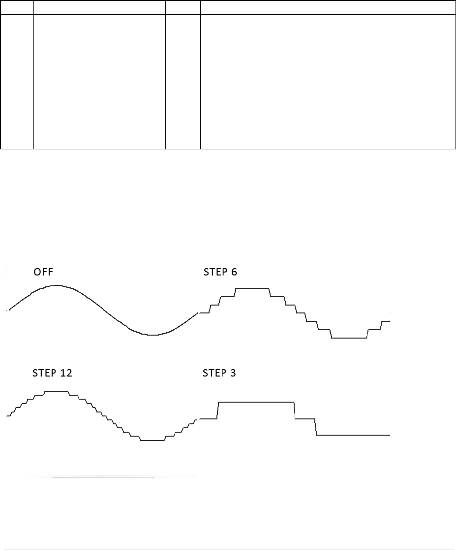
STEP: LFO waveform stepping.
Ex:
SOUND MODELS
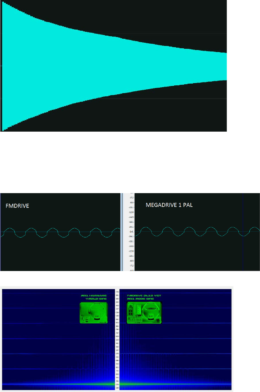
MD1 SEGA MEGADRIVE MODEL 1
FMDRIVE try to approximate the real hardware distortion
HARMONIC DISTORTION – LADDER
As previously stated, the first generation of SEGA MEGADRIVE consoles produced harmonic
distortion. It gives the sound a special character that actually no software has emulated before.
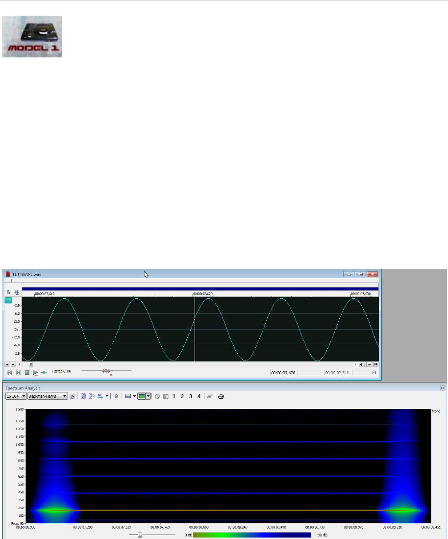
Consider a pure sine wave signal at 440 Hz; it will ideally produce only one strong frequency at 440
Hz. However observing the Megadrive sine on a Spectral analyzer and on oscilloscope, shows a lots of
harmonics components are added to the original frequency and also a change on the sine shape,
resulting in a richer distorted sound. The effect is even more pronounced the lower TL is. This unique
sound problem to the YM2612 DAC is called “The Ladder effect”. And can be used creatively.
When using MD1 Model the Overdrive parameter allows to fine tune the effect to taste, most
notably when ALGO 7 is in use, the output might distort too much. (Different Sega models and
revision will produce different result in real world.)
The Sine wave also can clip when TL is set to 0 (max volume).
ENVELOPE CYCLES
YM2612 Attenuation Values:
The envelope generator maintains a 10-bit attenuation value for each operator following different
update cycles. Depending on the Rate setting at the moment of the update, the attenuation will
occur more often for high rates than
for low rates. This particular implementation is very practical
to obtain very long envelope time and still maintain accuracy at short settings.
However this actually means that you can hear stepping when a rate is low.
Ex: try this setting on MD1 sound model,
ALGO 0 , C2 TL = 0 AR=31 (DR,SL,D2R)=0,RR=15 // M2 TL=0 AR=31 (DR,SL)=0, D2R=2, RR=15
NOISE FLOOR
The Output resolution is also limited and no sound will be produced if TL is lower than 104.
Quantification noise could also be noticeable at very low volume settings or when the envelope
ends toward max attenuation value.
Here is a comparison between the FMDRIVE output and the Real SEGA hardware :
Very close spectrum between MD1 and FMDrive.
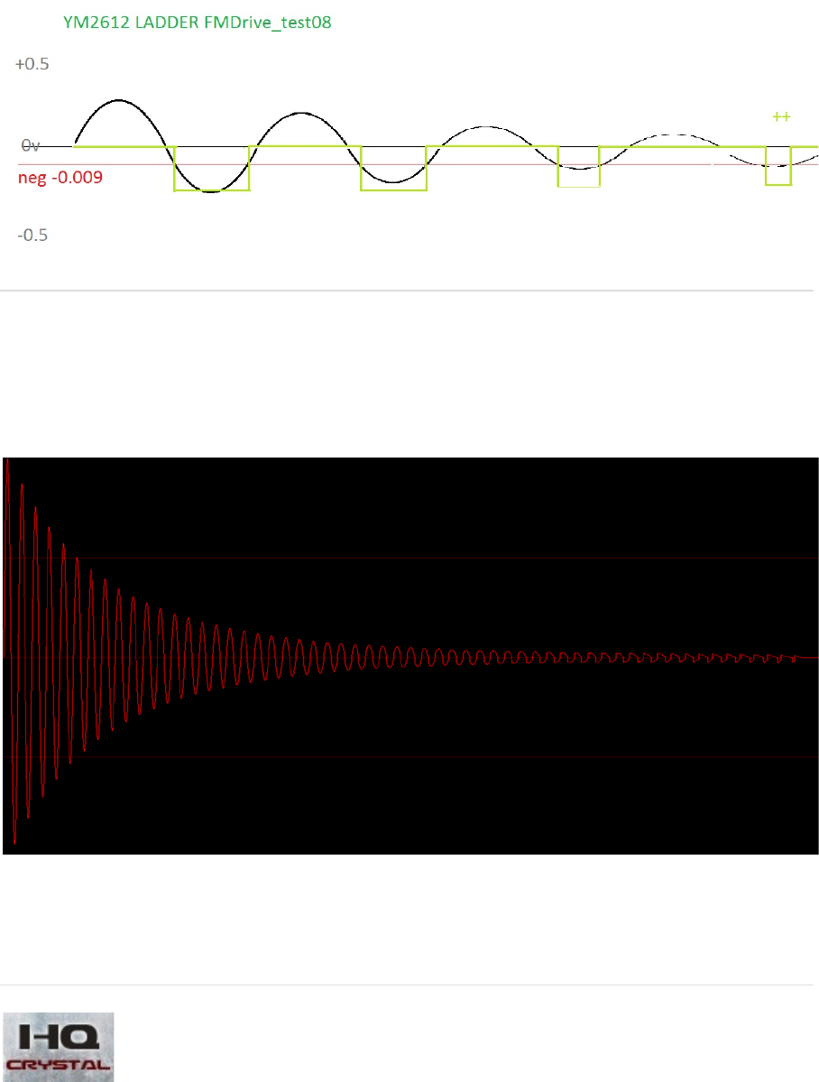
What I have found during close experimentation on the real chip is that the distorted part is actually
here even when the output register for a channel are zeroed out. This leads me to search for an
analog problem then trying to do basic reverse engineering; I have implemented a “negative value
bug” tha
t reproduces the effect closely, especially at the very end of an envelope where the signal
period also change…
HQ MODEL
Designing a new core adds the ability to completely remove the hardware limitation.
No harmonic distortion is produced in this mode, just perfect sine.
Output resolution if far more capable using 24 Bit resolution as are
the envelope update cycles that

are maintaining high precision even at low rate value (high envelope times).
HQ Model will produce YM2612 sound at ideal capabilities, removing hardware limitation.
Ex: try the same setting as before with HQ sound model,
ALGO 0 , C2 TL = 0 AR=31 (DR,SL,D2R)=0,RR=15 // M2 TL=0 AR=31 (DR,SL)=0, D2R=2, RR=15
DEPENDING ON WHAT YOU NEED, these two sound models can provide a variety of n
uance, thus
enhancing the sound capabilities of FMDRIVE. Note that the stepping on some others parameters
like TL is also greatly improved in HQ mode…
FMDrive sound models can be changed into the CIRCUIT BENDING PANELS.
It can be done simply by clicking on the model in order to switch to the other.

NORMAL/SPECIAL
MODE
YAMAHA added to the YM2612 three different settings that produce a change in the global function.
NORMAL MODE
Under normal mode each operator will received the same root note (frequency) on each key on. The
frequency relation can be changed harmonically with the MUL parameter or detuned by DT (also DT2
on FMDRIVE).
SPECIAL MODE
Under special mode each operator on channel 3 can have a different root frequency setting,
allowing special effects and more inharmonic sounds. (The frequency can also be entered with the PC
keyboard on FMDRIVE GUI for precise setting and more decimal points, ex: 221.25Hz).
At initialization, every operator frequencies are tied to MIDI CH1. Setting a different frequency will
change the root note, so if you play an A 440Hz on the keyboard, having 540Hz on Operator M2
will play 540Hz instead of 440Hz. This means that operator M2 is detuned by 100Hz from the note
played.
However you can optionally “Freeze” the frequency of all the operators (M1, C1 or M2) to have a
fixed frequency setting. This means that if you play an A 440Hz on the keyboard, having 540Hz on
Operator M2 will play 540Hz instead of 440Hz but playing a C note will still play 540Hz on M2.
This can be done by activating the FREEZE button on the TL panel.
(When freeze there will be a “freeze indicator” next to the frequency on each operator panel, it is not
working when external MIDI switch is set even if Freeze is activated)
Activating the MIDI switch next to an OPERATOR allows frequency and key on / off happening
independently. Controls are made by a different MIDI channel for M2, C1 and M1.
MIDI MAPPING for SPECIAL MODE MIDI ON
• M2 is controlled by MIDI CH11
• C1 is controlled by MIDI CH12
• M1 is controlled by MIDI CH13
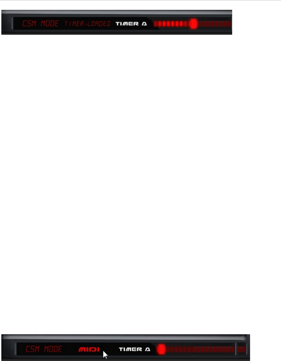
CSM MODE
CSM (illegal Mode)
This mode is will also switch the YM2612 in special mode
It was officially called “Illegal Mode” because it seems SEGA did not find any use of this or developers
found it too hard to program…
CSM stands for COMPOSITE SINE WAVE MODELING aka early speech synthesis system
What this do is automatically Key on /off operators very fast, precisely at the speed of TIMER A*
Each time the Operator is key on, the phase is restarted, this happens so fast that we actually hear a
tone instead of a looping envelope. This method of synthesis tends to produced what is called vocal
formants.
As there is 4 Operators, different settings on TL volume and frequencies at precise timing plus
different TIMER values can mimic a talking voice and produce vocal sound and even words.
However there are no easy implementation or values tables internally in the YM2612 chip. All of this
should be programmed by software. Implemented a complete speech synthesis system could have
been great but nothing was done in this way for YM2612 by YAMAHA.
FMDRIVE does not include a speech driver, but adds interesting new control over the CSM
*TIMER A is one of the two onboard timers of the YM2612 chip.
The lowest period is 18.4ms (19.4 PAL) and the shortest is 18µs. Very fast period produce very high
frequencies, higher than 40 000 Hz! this is why FMDRIVE limit the highest period to 1.13636ms = A5,
it saves CPU and still maintains the useful musical range.
In conjunction with the SPECIAL MODE external MIDI control, we can produce interesting talking
vocal effects.
Activating the MIDI switch next to the TIMER A allows the frequency of the period to be controlled
by MIDI notes (in the limit of TIMER A speed), turning the CSM mode into another useful filtered
vocal singing waveform and enhancing the FMDRIVE variety of sound.
MIDI MAPPING for CSM TIMER A MIDI ON
• Timer A Frequency/Period is controlled by MIDI CH14
In CSM mode only the Release Rate RR will have a noticeable effect on the sound.
NOTE: On the YM2612, Performing a manual key on will overwrite CSM key on/off and deactivate the
effect until manual key off. Also the EG has little to no effect on the fast key on, key off events
happening in CSM mode. However if an attack phase is set (AR>30) no sound will be produced.
FOR MORE PRACTICAL USE, FMDRIVE ACTIVATE THE CSM MODE on each CHANNEL 1 MIDI KEY ON
and DEACTIVATE on each CHANNEL 1 MIDI KEY off and EG is bypassed.
IMPLEMENTING THIS CSM FEATURE ON THE REAL SEGA GENESIS HARDWARE could be done in future
GENMDM Updates.
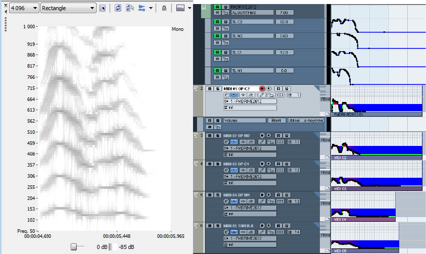
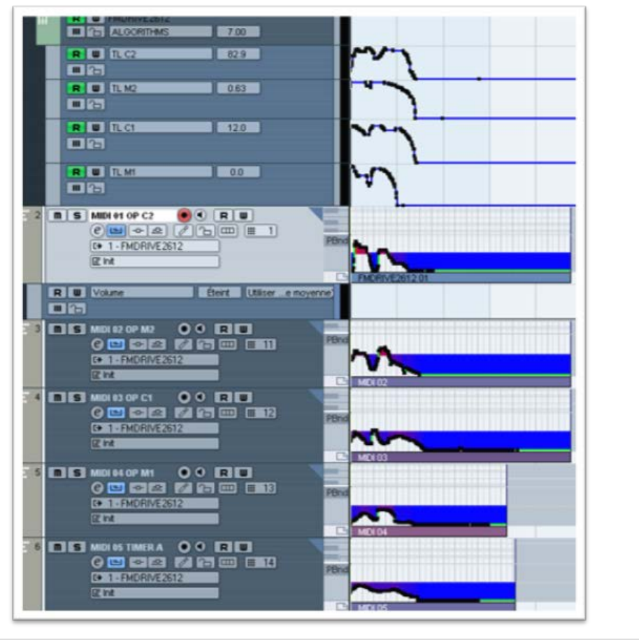
A practical way for using the CSM mode is MIDI automation. Use Midi Channels 11, 12, 13 and 14 in
your DAW to control Operators frequencies and Timer A by Midi notes. Pitch bend values can add
to the natural vocal tone of the sound.
Here you can see the word Hello programmed in Cubase, with automation similar to the vocal
spectrum at the left.
Try to produce a formant by playing notes on the keyboard and setting different frequencies for
each operator. CSM Speech is most effective on Algorithm 7 when all operators are non-
modulated, in order to produce a sum of sinusoids similar to the FFT approach.
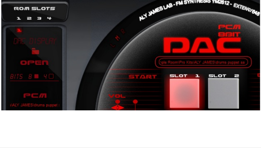
D.A.C
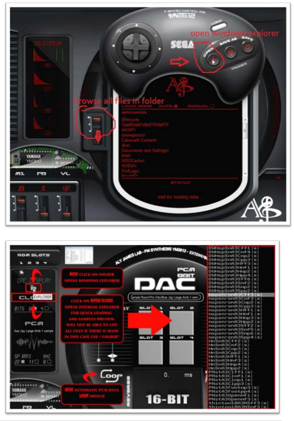
LOADING SAMPLES
The YM2612 has the ability to play 8bit PCM sound data instead of FM sound on the Channel 6.
It is useful to play complex sounds; effects, vocals and percussions that FM alone could not
reproduce. Activating the DAC disable the FM part.
FMDRIVE has 4 SLOTS to load sample data from wave files. (.WAV) and will play them like on the
Megadrive with a crunchy sound.
Click on the OPEN button to browse your hard drives and load WAV files. (Avoid using very long
paths for folders as they might not be scanned) or click on the folder to use windows explorer with no
limitation of location.
A global SAMPLE RATE CONTROL allows outputting 22 KHz, 11 KHz or 8 KHz.
A global BIT RATE CONTROL allows switching between 8bit and 4bit.
The start and end sliders controls the starting point and ending point of the loaded sample data.
The pitch slider controls the playback rate and the LOOP switch toggles the data loop mode on or
off.
SLOTS are MAPPED to standard midi GM drums. MIDI CH1 Notes like so:
MIDI MAPPING for DAC SAMPLE SLOTS
• Slot 1 MIDI notes 35, 36 (KICK)
• Slot 2 MIDI notes 38, 40 (SNARE)
• Slot 3 MIDI notes 41, 43, 45 (TOM1)
• Slot 4 MIDI notes 42, 44,46 (HIHAT)
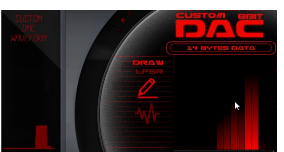
CUSTOM WAVEFORM
14 bytes of data can also be directly written to the DAC allowing the use of raw custom waveforms.
(this feature is also possible on a real YM2612).
DRAW MODE allow direct draw of the shape on the GUI.
LFSR MODE randomly generates data bytes on each key on. This produces a constantly changing
waveform. The rate of the random change is governing by the clock speed.
LFSR CLOCK is sync to the HOST tempo. That means that it will be in sync with the song. A divider will
change the clock speed regarding the master tempo.
Example of the LFSR output waveforms
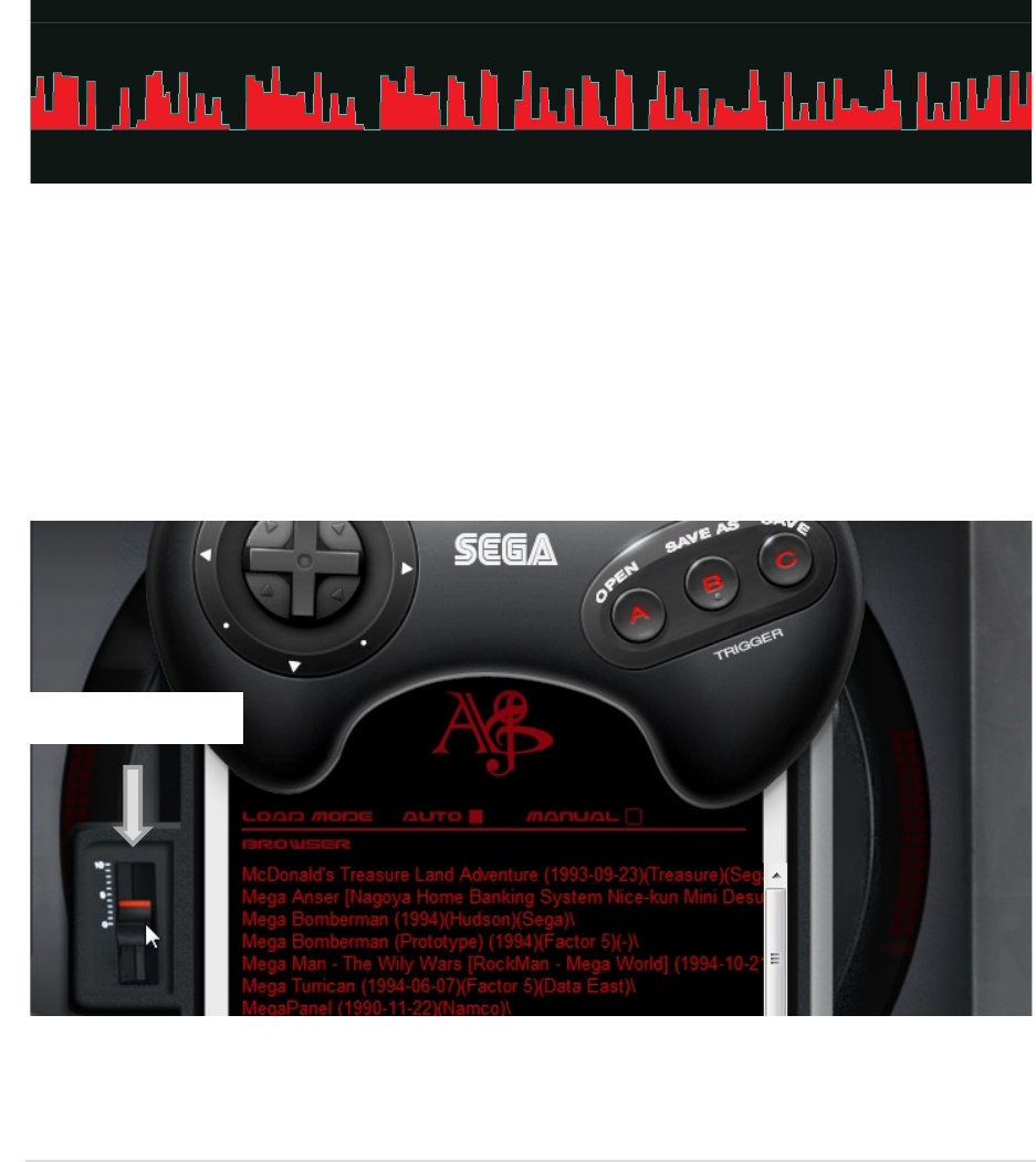
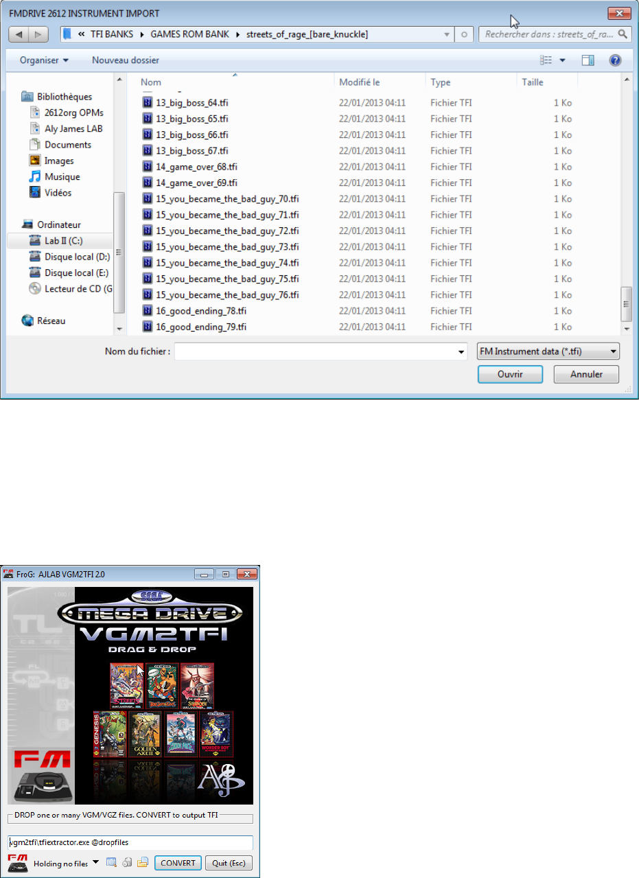
TFI IMPORT / EXPORT
TFI FORMAT
The TFI format is a 42 Bytes binary file, it contains register values for the main parameters of the
YM2612 chip.
FMDRIVE has the ability to load and save TFI file format that is compatible with most of the YM2612
software. Tools allow extracting instruments for original SEGA MEGADRIVE Games VGM music on a
per song basis.
The VGM format is a standard for YM2612 register writes, it contains all of the data that the chip or
game emulators will need to play a song.
LARGE SCROLLING
The internal browser is limited to a certain number of characters so you will have to put your TFI
preset folder into the root location C: if there is any problem. However there is no problem with that
if you use the OPEN button on the JOYPAD to load from any location using the windows explorer.
The tool VGM2TFI 2.0 allows extracting TFI instruments from a loaded YM2612 VGM music file.
This means that you can load thousands of instruments from your favorite VGM songs. It could be a
start for designing your own instrument or simply a large database of presets. Also, certain game
emulators (Regen, GenKmod…) have the ability to save TFI presets from the game being emulated.
LIMITATION
TFI format contains all of the main parameters that define an YM2612 sound.
However the TFI format does not contains data for:
• LFO
• DAC
• EXTENDED FEATURES
That means that:
• You will need to use ONLY PARAMETRIC EG and activate all Operators when loading TFI
• LFO parameters will not be loaded or saved with the TFI patch
• DAC will not be loaded or saved
• SPECIAL MODE frequencies, CSM and DT2 will not be saved
You can of course save all these information in the native FMDRIVE PATCH format from the main
panel
LIST OF PARAMETERS
AUTO & MANUAL MODE when switched to AUTO, TFI preset is loaded immediately after clicking in
the GUI browser. In MANUAL you need to select it first then click on the GAME PAD LOAD button.
BE SURE TO BE IN MANUAL MODE IF YOU SEND A MIDI PROGRAM CHANGE WHEN TFI PANEL IS
ACTIVE TO PREVENT AUTOMATIC DATA LOADING ATTEMPT
SAVE & SAVE AS will save the actual FMDRIVE data to a TFI file. Save will save the preset at the
current location and save as allows specifying the location.
OPEN will use the standard WINDOWS browser to search for files that may not be accessed by the
GUI browser (if folders names or path are too long)
The actual registers data and the last changing parameter are displayed on the TFI GUI Panel and can
also be saved as a simple text file for further conversion.
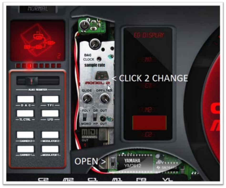
CIRCUIT BENDING
The FMDRIVE add the unique ability to tweak the system in many ways. Opening the tweaking panel
lead you to these following controls over the FM engine:
GLOBAL VOLUME: useful to adjust the level when clipping occurs or boosting some TFI patches that
may be too quiet
POLY & MONO: switches between 3 Voice polyphony and mono voice. Keep in mind that on the real
console each channel is always mono and polyphony were only achieved by using multiple channels.
GLIDE: two parameters to controls the amount of time the pitch will reach the note played.
DR or HP = Direct Output or Headphone out filtering (can add analog feeling to the sound)
OP FILTER: a GLOBAL parameter that will filter out high frequencies during phase modulation. Leave
to max for MD1 realistic emulation. Can be used to reduce the harshness of the sound at high
frequencies, reduce aliasing and also be used as an automatable low pass filter
SAMPLE RATE DEGRADATION: can degrade the audio output signal by skipping samples. When set to
max it switches to POLYRATE.
POLYRATE: degrade the output according to the number of voice being played.
“Polyrate” is a kind of dynamic sample rate reducer.
MIDI AUTOMATION
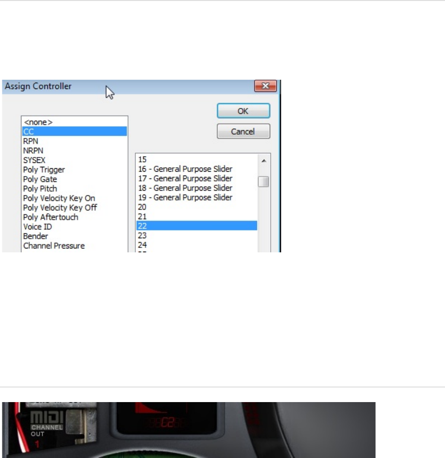
MIDI LEARN
Almost all of the FMDRIVE parameters can be automated via midi learn or DAW automation allowing
great control over the sound. (Excepted graphic envelope parameters)
Simply right click on a button, knob or slider to assign external MIDI Control or use DAW automation.
Almost all type of MIDI message can be assigned or MIDI learned.
NOTE: If a TFI preset is loaded during an automation recording, every registers change will be
recorded. It can be a fast way to write automation different than global MIDI program change.
MIDI OUT
All assigned midi parameters will also send MIDI OUT message. The MIDI OUT Channel is chosen via
the tweak panel.
All assigned MIDI parameters will send MIDI OUT data on global patch change.
You can also sync parameters between different FMDRIVE instances, using one instance to control
the others via MIDI.
Ex: Assign LFO ON/OFF to CC 25 on each instance of the plugin. Then allow other instance to receive
MIDI in from the FMDRIVE chosen master Instance. Now each time you activate or deactivate the LFO
from the master instance of the plugin, all others will follow.
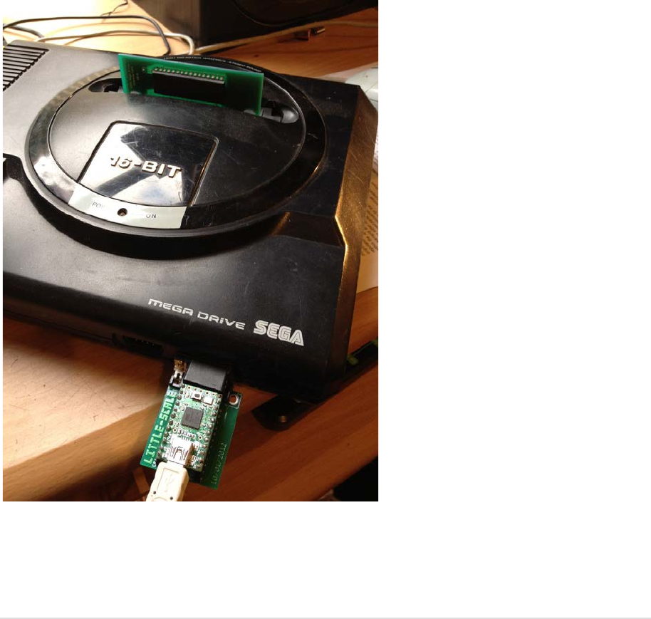
GENMDM
The GENMDM is a midi hardware interface created and designed by Sebastian Tomczak that allows
the real SEGA MEGADRIVE/GENESIS to understand MIDI data. It means you can control the YM2612
sound chip in real time via MIDI. (The PSG SN76489 sound chip is also supported and will also be
controllable via a separate VST plugin in the future)
FMDRIVE can act as a visual controller for the interface allowing more user friendly control over the
huge list of parameters and visual feedback. (See the GENMDM Control MANUAL)
The VST plugin can control the GENMDM by setting the appropriate MIDI CC on each parameter.
However a special VST version ”GENMDM CONTROLLER ONLY” is provided with all the MIDI CC pre
assigned and no sound emulation. This is more practical than loading the emulation engine and
saves CPU resources. (Controller version still in development for 1.2)
Some of the extended features are not available yet on GENMDM such as GRAPHIC ENVELOPES, CSM
and custom parameters. Some are still in development and could be implemented in future FMDRIVE
and GENMDM updates.
PARAMETERS LIST
GLOBAL PANEL
L M R = output the FM sound hard left, center or hard right
ALGO REGISTER= Switch between different Operator configuration
DAC = Disable FM, Activate the DAC an open the DAC control panel
TFI = Open the TFI control panel
TL CTRL = Open the TL control panel
LFO = Open the LFO control panel
CARRIER2, 1, MODULATOR 2, 1 = Open the chosen Operator panel (you can do the same by clicking
on the op name on EG Display)
NORMAL/SPECIAL = switches between normal and special mode

TL PANEL
POWER = reset OPERATORS, FEEDBACK and VELOCITY
TL = Total attenuation level of the selected Operator
FB = Feedback level of Operator M1
VL = Global velocity sensitivity for all Operators (per operator enabled)
VOICES = Controls the amount of voice in polyphonic mode (3 or 6)
FREEZE = Assign a fixed frequency behavior in SPECIAL MODE
OVERDRIVE = Controls the amount of ladder effect in MD1 mode (max is like the real chip)
OPERATOR PANEL
POWER = Disable or enable the operator to receive key on/off commands
KS = Key Scaling level. Reduce the envelope time according to the note pitch
MUL = Root frequency multiplier
DT1 = Small detune
DT2 = Large detune
AM= Enable or disable amplitude modulation by LFO
PMS = Level of pitch modulation by LFO (Global or Unsync)
SSG = Disable or set the specified SSG envelope sequence
AR = Attack rate
DR = First decay rate
SL = Secondary amplitude level (sustain point)
D2R = Secondary decay rate

RR = Release rate
SPECIAL MODE & CSM PANEL
F-NUMBER = the root frequency of the current operator
RESET = Reset the root frequency to 440 Hz (ratio 1:1)
MIDI = activate external midi control for that operator and / or for Timer A
TIMER A = Speed of the Timer Period
LFO PANEL
POWER = Enable or disable LFO
FRQ = Frequency of the LFO
AR = LFO PMS AMS attack rate
RR = LFO PMS AMS release rate
WF = Waveform shape of the LFO
AMS = Amplitude modulation sensitivity
PMS = Pitch modulation sensitivity
PMS REG = choose between normal or un-sync PMS
LFO FRQ = choose between normal or custom LFO frequency
STEP = LFO waveform stepping

FM SYNTHESIS
WHAT IS FM?
Frequency Modulation (yes, the same as that thing you listen to on the radio) synthesis was made
popular by Yamaha in the early 1980s with their line of DX synthesizers, which were instrumental in
both the downfall of classic analogue synths, and giving keyboard players worldwide a polyphonic-
palette of groundbreaking new sounds to use.
Dedicated FM synthesizers are digital in nature due to the instability of analogue VCOs, and the
nature of FM synthesis techniques makes it very easy to create un-pitched and metallic tones, rather
than standard subtractive sounds.
FM synthesis is based on two key things – a ‘modulator’ oscillator, and a ‘carrier’ oscillator. These
oscillators usually both use a sine waveform, and from this the modulator oscillator works just like an
LFO – because it modulates the frequency/pitch of the carrier oscillator. You can try this yourself on a
normal subtractive synthesizer, by setting up a sine wave oscillator and an LFO, and using the LFO to
modulate the pitch of the oscillator – as you increase the rate of the LFO, the sound becomes non-
harmonic. Note that in FM synthesis, the word ‘oscillator’ is often replaced with the term ‘operator’.
As you change the modulation of the carrier operator, the frequency of the carrier will constantly
move up and down depending on how the modulator is set up and in doing this different harmonics
are created (called ‘sidebands’), because these harmonics surround the carrier frequency depending
on how it is modulated.
Because of the somewhat lifeless sound of the operators, FM synthesizers tend to include
somewhere around 4-8 operators on a synth to spice things up.
These extra operators can be routed in all sorts of different and interesting ways, called ‘algorithms’.
For example, with the addition of an extra modulator operator, we can arrange the operators so that
they go ‘’modulator 1’ & ‘modulator 2’ go into the carrier’, or ‘modulator 1 goes into modulator 2,
which goes into the carrier’ – this being more complicated and creating a new waveform.
Therefore, using many operators can produce unique and lifelike sounds unachievable with other
types of sound synthesis.
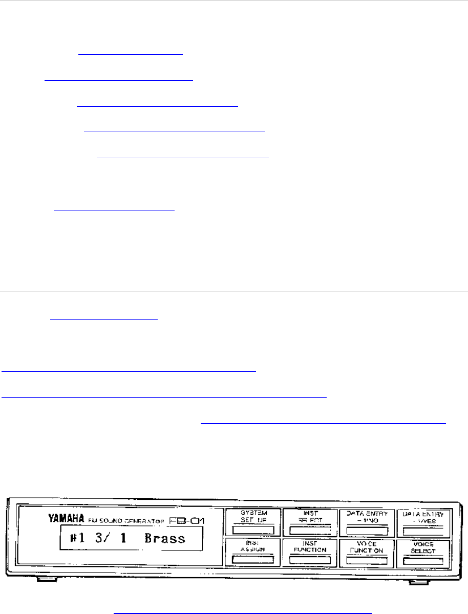
APPENDIX
Early Interface design sketch & design
Some hints…
LINKS
Aly James centric links
Official Website www.alyjameslab.com
Dev Blog www.alyjameslab.blogspot.com
Facebook News www.facebook.com/alyjamesound
Youtube Channel www.youtube.com/alijamesproduction
Soundcloud demos http://www.soundcloud/alyjameslab
Twitter @alyjamestwitt
CONTACT alyjames.info@gmail.com
External links
GENMDM http://little-scale.com/
An Introduction to FM
https://ccrma.stanford.edu/software/snd/snd/fm.html
http://www.soundonsound.com/sos/apr00/articles/synthsecrets.htm
YAMAHA YM chips numerical classification http://www.vorc.org/text/column/hally/ymxxxx.html
YAMAHA FB01
This box is basically an YM2151 in the box with MIDI IN & OUT same as YAMAHA CX5M computer.
Get one!
Maxim’s YM2612 INFOS http://www.smspower.org/maxim/Documents/YM2612

HOPE YOU HAVE FUN WITH FMDrive!

DISCLAIMER &
LICENCE AGREEMENT
DISCLAIMER
FMDRIVE (the software) is provided as-is, without warranty of any kind. Aly James Lab
(alyjames.info@gmail.com, the Author) disclaim all warranties relating to the Software, whether
express or implied, including but not limited to any implied warranties of merchantability and fitness
for a particular purpose, and all such warranties are expressly and specifically disclaimed. The Author
shall not be liable for any indirect, consequential or incidental damages arising out of the use or
inability to use the Software even if the Author has been advised of the possibility of such damages
or claims. The user of the Software bears all risk as to the quality and performance of the Software. If
your computer blows up, I say "I wasn’t there!" of course that should not happen…
LICENCE AGREEMENT
FMDRIVE is copyright © 2013 Aly James.
FMDRIVE (the software) is not public domain, and is protected by the copyright laws of the
international community. In using FMDRIVE, you are not obtaining title to FMDRIVE or any
copyrights. You may not sublicense, rent, lease, convey, distribute copy, modify, translate, convert to
another programming language, decompile, or disassemble the Software for any purpose. You may
only redistribute the Software for promotion purpose with Aly James prior written permission.
Where redistribution is authorized in writing by the Author, FMDRIVE must be redistributed in its
original archive format, and must not be modified in any way. All such authorized redistribution must
be accompanied by clear messages stating the origin of the software as an Aly James Lab product,
this license, a link to the Website alyjameslab.com. The user ID is hard coded into the GUI and each
version of the software is unique.
By Using the Software, you are agreeing to this disclaimer and license.
VST is a trademark of Steinberg Media Technologies GmbH.
FMDRIVE does not emulate a Sega Megadrive console but the sound chip that was inside; witch basic
function is reproduced here but enhanced a lot. It is not a straight binary copy and the system is
totally new.
Secondly the use of Sega name and logo is use strictly here for the legitimate purpose of comparison
and tribute to this great console, and it does not in any way imply SEGA®'s or YAMAHA®'s permission
or endorsement of the FMDRIVE product.
