Seiko Epson WN6501C 802.11a/b/g Module User Manual 00
Seiko Epson Corporation 802.11a/b/g Module 00
Contents
- 1. Epsom Projector Manual 1
- 2. Epsom Projector Manual 2
- 3. Prelim OEM Integrator Manual
- 4. Epson Projector Manual 1
- 5. Epson User Manual 2
- 6. Revised Manual
Prelim OEM Integrator Manual

WN6501CEP
Wireless LAN 802.11a/b/g USB adapter
QIG DRAFT

iii
C
OMPLIANCES
We: Epson America, Inc.
Located at: 3840 Kilroy Airport Way
MS: 3-13
Long Beach, CA 90806
Tel: 562-290-5254
Declare under sole responsibility that the product identified herein, complies with 47CFR
Part 2 and 15 of the FCC rules as a Class B digital device. Each product marketed, is identical
to the representative unit tested and found to be compliant with the standards. Records
maintained continue to reflect the equipment being produced can be expected to be within
the variation accepted, due to quantity production and testing on a statistical basis as required
by 47CFR 2.909. Operation is subject to the following two conditions: (1) this device may not
cause harmful interference, and (2) this device must accept any interference received,
including interference that may cause undesired operation.
Trade name: Epson
Type of Product: Wireless Module for Espon projector
Model: WN6501CEP
DECLARATION of CONFORMITY
According to 47CFR, Part 2 and 15
Class B Personal Computers and Peripherals; and/or
CPU Boards and Power Supplies used with Class B
Personal Computers

C
OMPLIANCES
iv
FCC Compliance Statement
For United States Users
This equipment has been tested and found to comply with the limits for a Class B digital
device, pursuant to Part 15 of the FCC Rules. These limits are designed to provide reasonable
protection against harmful interference in a residential installation. This equipment generates,
uses, and can radiate radio frequency energy and, if not installed and used in accordance with
the instructions, may cause harmful interference to radio or television reception. However,
there is no guarantee that interference will not occur in a particular installation. If this
equipment does cause interference to radio and television reception, which can be
determined by turning the equipment off and on, the user is encouraged to try to correct the
interference by one or more of the following measures.
• Reorient or relocate the receiving antenna.
• Increase the separation between the equipment and receiver.
• Connect the equipment into an outlet on a circuit different from that to which the receiver
is connected.
• Consult the dealer or an experienced radio/TV technician for help
This device complies with Part 15 of the FCC Rules. Operation is subject to the following
two conditions:
(1) This device may not cause harmful interference, and
(2) this device must accept any interference received, including interference that may cause
undesired operation.
WARNING
The connection of a non-shielded equipment interface cable to this equipment will invalidate
the FCC Certification or Declaration of this device and may cause interference levels which
exceed the limits established by the FCC for this equipment. It is the responsibility of the user
to obtain and use a shielded equipment interface cable with this device. If this equipment has
more than one interface connector, do not leave cables connected to unused interfaces.
Changes or modifications not expressly approved by the manufacturer could void the user’s
authority to operate the equipment.
FCC Radiation Exposure Statement:
The wireless LAN 802.11a/b/g adapter Model: WN6501CEP complies with FCC radiation
exposure limits set forth for an uncontrolled environment. This device should be installed
and operated with minimum distance 20 cm between the radiator and your body.
The holder of the grant of equipment authorization (Grantee) of the module is responsible
for the compliance of the module in its final configuration, provided that the OEM,
integrator, and/or end user has complied with all of the instructions provided by the Grantee
which indicate installation and/or operating conditions necessary for compliance.

C
OMPLIANCES
v
The modular transmitter must be labeled with its own FCC ID number, and, if the FCC ID is
not visible when the module is installed inside another device, then the outside of the device
into which the module is installed must also display a label referring to the enclosed module.
This exterior label can use wording such as the following: “Contains Transmitter Module
FCC ID: BKMWN6501C” or “Contains FCC ID: BKMWN6501C.” Any similar wording
that expresses the same meaning may be used. The Grantee may either provide such a label,
an example of which must be included in the application for equipment authorization, or,
must provide adequate instructions along with the module which explain this requirement. In
the latter case, a copy of these instructions must be included in the application for equipment
authorization.
DGT WARNING
經型式認證合格之低功率射頻電機,非經許可,公司、商號或使用者均不得擅自變
更頻率、加大功率或變更原設計之特性及功能。
低功率射頻電機之使用不得影響飛航安全及干擾合法通信;經發現有干擾現象時,
應立即停用,並改善至無干擾時方得繼續使用。
前項合法通信,指依電信法規定作業之無線電通信。
低功率射頻電機須忍受合法通信或工業、科學及醫療用電波輻射性電機設備之干
擾。
Article 14
Without permission, any company, firm or user shall not alter the frequency, increase the
power, or change the characteristics and functions of the original design of the certified lower
power frequency electric machinery.
Article 15
The application of lower power frequency electric machineries shall not affect the navigation
safety nor interfere a legal communication, if an interference is found, the service will be
suspended until improvement is made and the interference no longer exists.
The foregoing legal communication refers to the wireless telecommunication operated
according to the telecommunications laws and regulations. The lower power frequency
electric machinery should be able to tolerate the interference of the electric wave radiation
electric machineries and equipments for legal communications or industrial and scientific
applications.

C
OMPLIANCES
vi

1-1
C
HAPTER
1
Wireless LAN 802.11a/b/g USB adapter
Introduction
Thank you for purchasing the Wireless LAN 802.11a/b/g USB adapter. You
are about to install a networking system that is not only fast and powerful,
but also easy to set up and simple to maintain. In a short time you and
those in your network will be able to share a local printer and files, access
the Internet, and roam about the office wire-free.
Using radio frequency (RF) technology, WLAN’s transmit and receive data
over the air, minimizing the need for wired connections. Thus, WLAN’s
combine data connectivity with user mobility, and, through simplified
configuration, enable movable LAN’s.
This wireless networking solution has been designed for both large and
small businesses, and it is scalable so that you can easily add more users
and new network features as your business grows.
Wireless LAN 802.11a/b/g USB adapter
1-2
System Requirements
Your system must meet the following minimum requirements:
• Networked devices must be running Windows 98, 2000, Me, or XP
• Pentium Class CPU, 700 Mhz or faster processor
• 128 MB RAM (recommended)
Hardware Description
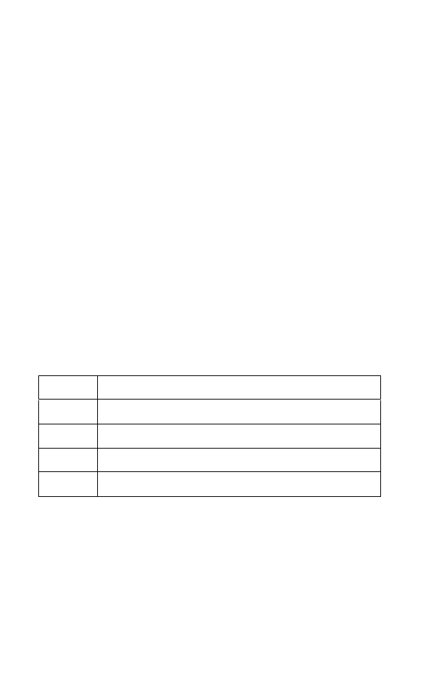
LED Indicators
The Wireless LAN 802.11a/b/g USB adapter is equipped with one LED
indicator.
Front Panel LED
Status Description
Green Link is up.
Blink Radio is scanning.
Off Radio is off.
Flashing Traffic on the connection.
I
NSTALLATION
1-3
Installation
First off, you must install the Wireless LAN 802.11a/b/g USB adapter software.
This utility will allow you to manage and control the device.
Note: The screen shots below depict the setup process on a computer
running Windows XP. If you are using a different operating system
on your machine, the screen shots may differ slightly.
1. Insert the CD into your CD-ROM drive.
2. To install RALINK Wireless utility, simply run the program and click
through the on-screen steps.
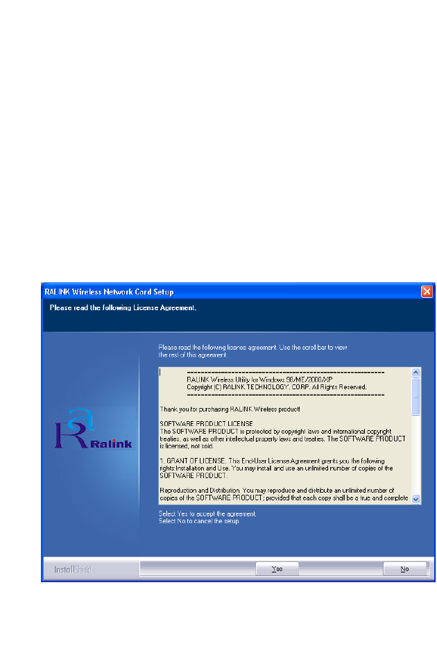
3. When the License Agreement screen displays, click Yes to begin the
installation process.
Wireless LAN 802.11a/b/g USB adapter
1-4
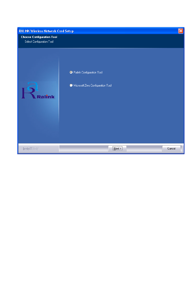
4. Choose Ralink Configuration Tool and click Next>.

I
NSTALLATION
1-5
5. Choose Optimize for Wi-Fi mode and click Next>.

Wireless LAN 802.11a/b/g USB adapter
1-6
The screen shot above shows the setup process copying files to your
machine.
I
NSTALLATION
1-7
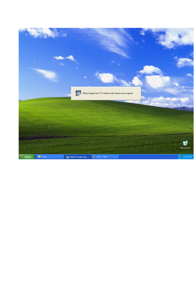
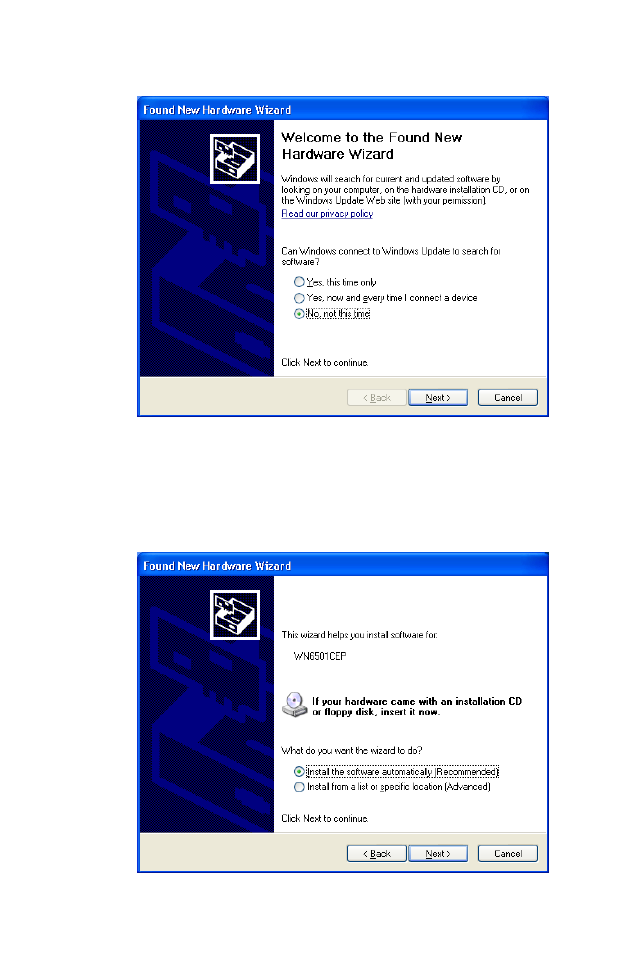
Please insert your Wireless LAN USB adapter now. Your computer will
automatically detect the Card. The next step is to click through the Found
New Hardware Wizard.
Wireless LAN 802.11a/b/g USB adapter
1-8
Note: On computers running Windows XP Service Pack 2 only.
Choose No, not this time and click Next>.
Choose Install the software automatically (Recommended) and click
Next>.
I
NSTALLATION
1-9
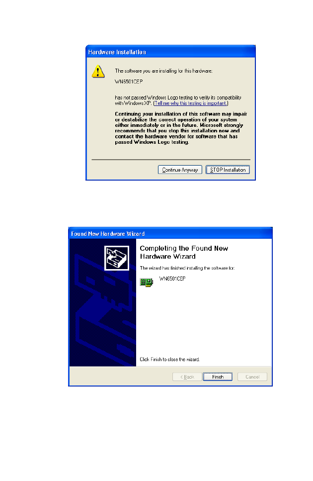
Click Continue Anyway.
Click Finish.
Wireless LAN 802.11a/b/g USB adapter
1-10
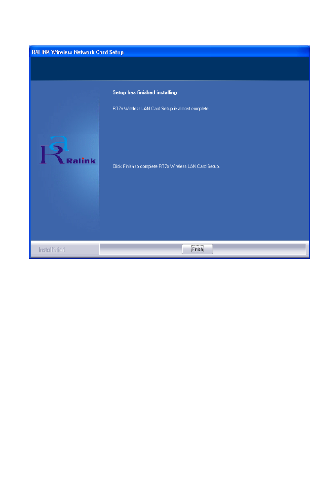
Click Finish. Congratulations! You have now completed the setup process.
C
ONFIGURATION
1-11
Configuration
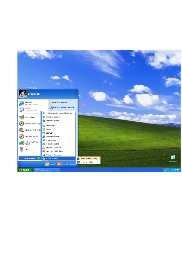
The next step is to configure the software.
To open the RALINK Wireless Utility, click Start and then All Programs.
The utility has five tabs:
•Link Status
•Site Survey
•Statistics
• Advanced
• About
Wireless LAN 802.11a/b/g USB adapter
1-12
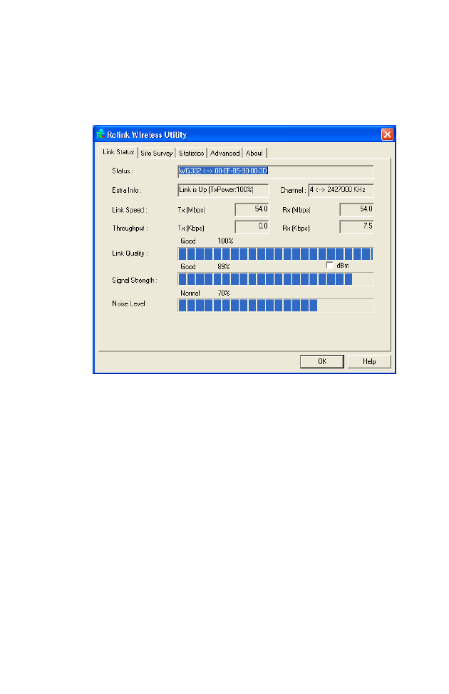
Link Status
The Link Status screen displays information on the current wireless access
point to which you are connected.
Status - Displays the BSSID (Basic Service Set ID) of the access point to
which the Wireless LAN USB adapter is associated. The BSSID is
the 6-byte hexadecimal ID number (the MAC address) of the associated
access point or base station. This information is only displayed, and not
configurable. Clients that have been associated with the same access point,
will display the same BSSID.
Extra Info - Shows the transmit power as a percentage.
Channel - The channel used to connect with the access point.
Link Speed - The data transmission speed.
Throughput - The amount of data (kilobits) transferred per second.
Link Quality - Shows the link quality of the wireless connection as a
percentage.

C
ONFIGURATION
1-13
Signal Strength - Shows the strength of the connection between the
RALINK Wireless Network Card and the access point.
Noise Level - Displays the level of noise as a percentage. If the Noise
Level is too high, your wireless connection will be disrupted.
Wireless LAN 802.11a/b/g USB adapter
1-14
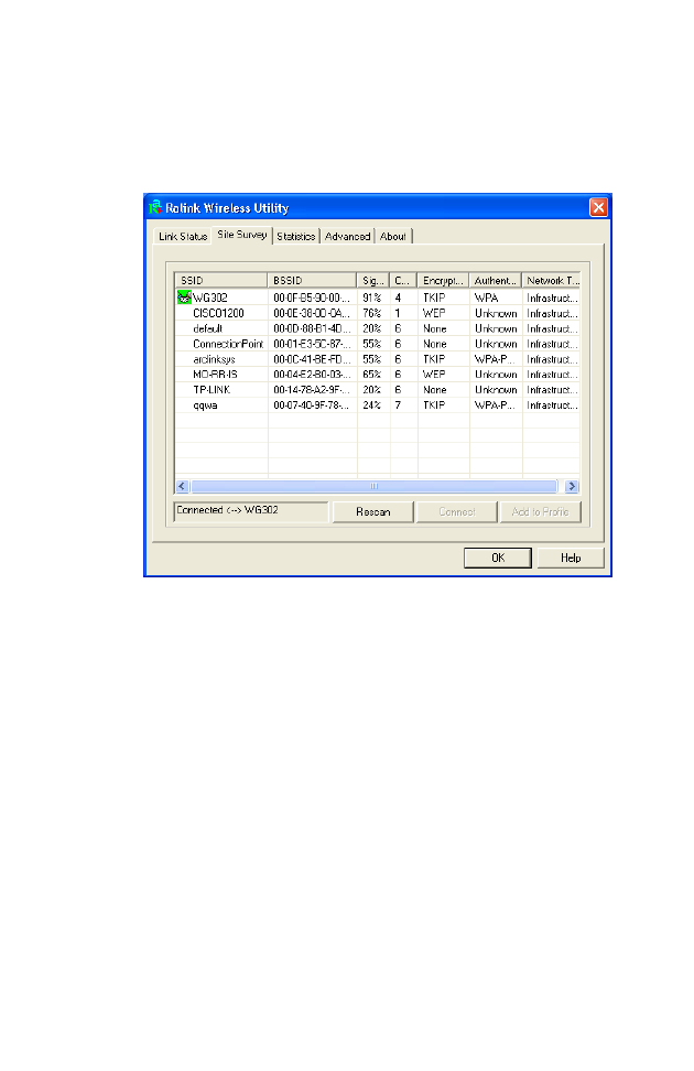
Site Survey
Site Survey scans and displays all wireless devices within range. Simply
double-click on the network you wish to join.
SSID - Service Set ID. The SSID is a code attached to all packets on a
wireless network to identify each packet as part of that network. It is
essentially the name of your network and can be up to a maximum of 32
alphanumeric characters in length. The green icon beside SSID WG302
shows you are connected to this network.
BSSID - Basic Service Set ID. The BSSID is the 6-byte hexadecimal ID
number (the MAC address) of the associated access point or base station in
an infrastructure network. In an ad hoc network, the BSSID is a random
number generated by the first station that communicates with other clients
on the network. This information is only displayed, and not configurable.
Signal - Displays the signal strength from the station to the listed access
points.
Channel - This is the channel used for the wireless connection.

C
ONFIGURATION
1-15
Authentication - Displays the authentication type in use. We recommend
enabling WPA for security purposes.
Network Type - This shows the operating mode of all listed access points.
Note: The text box on the bottom left of your screen names the access
point to which you are currently connected.
Rescan - Click Rescan to check for any new wireless networks within
range.
Wireless LAN 802.11a/b/g USB adapter
1-16
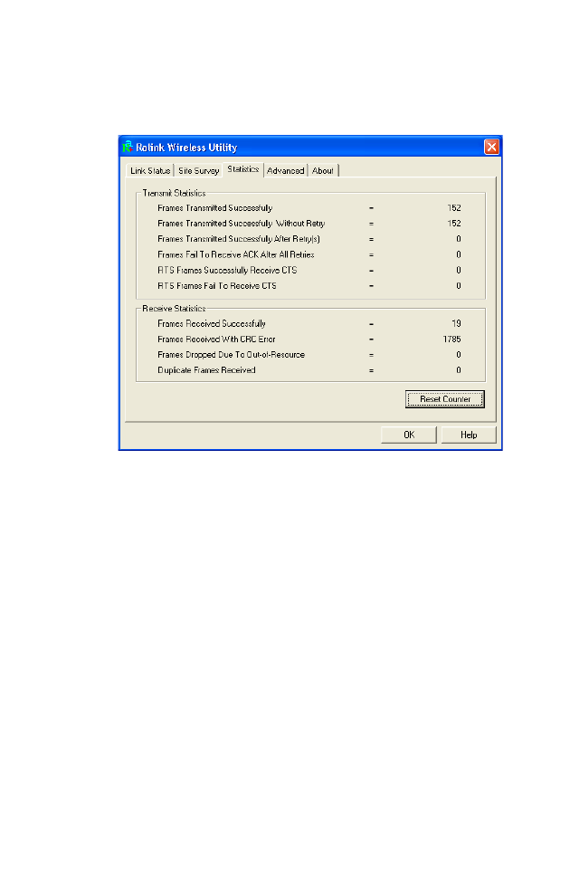
Statistics
The Statistics screen displays network connection information.
Use this feature to see how many packets have been successfully
transmitted and received on your network. The Reset Counter button
allows you to set all counters back to zero.
C
ONFIGURATION
1-17
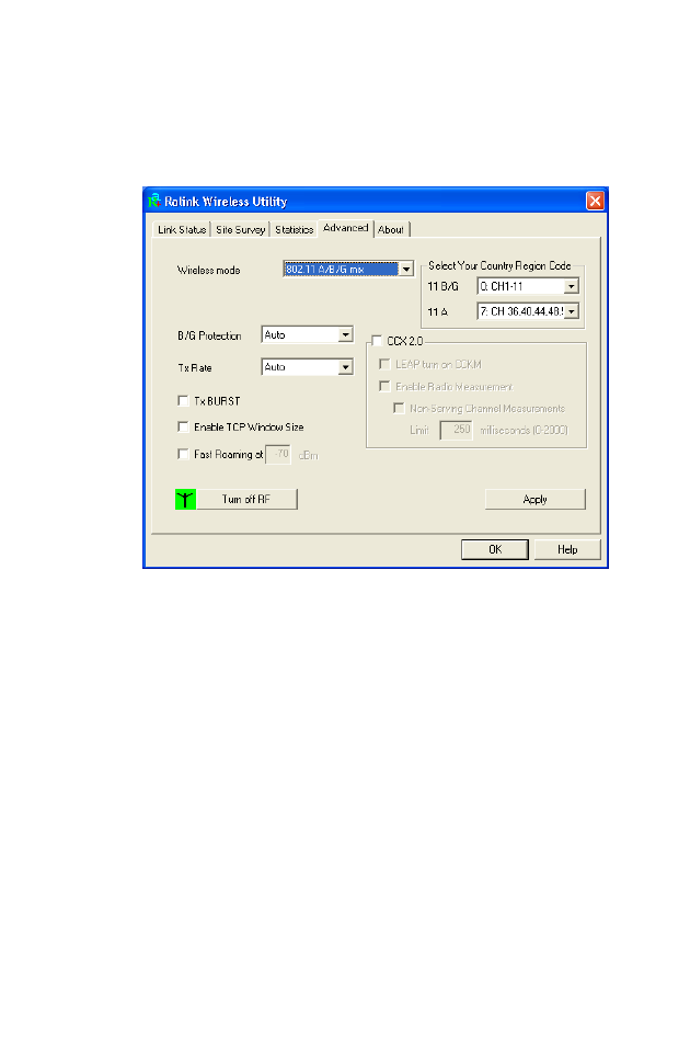
Advanced
The Advanced screen displays all the advanced network connection
information.
Wireless mode - The RALINK Wireless Network Card supports 802.11a,
802.11b and 802.11g mode. (Default: 802.11 A/B/G mix)
Select Your Country Region Code - Choose the Country Region Code
for 802.11b/g and 802.11a.
B/G Protection - Co-existing 802.11b and 802.11g networks can lead to
network conflicts. The final 802.11g standard includes a protection
mechanism to ensure mixed 802.11b and 802.11g operation. To get
optimum performance it can be helpful to enable this feature which allows
b/g to co-exist at the expense of performance. (Default: Auto)
CCX 2.0 - The Cisco Compatible Extensions (CCX) specification is for
makers of 802.11 wireless LAN chips for ensuring compliance with Cisco’s
proprietary wireless LAN protocols. (Default: Disabled)

Wireless LAN 802.11a/b/g USB adapter
1-18
Tx Rate - Indicates the data transmission rate. Select an appropriate
transmission speed. Lower speeds will give a better range. (Default: Auto)
Tx BURST - Burst transmission combines a very high data signaling rate
with very short transmission times. (Default: Disabled)
Enable TCP Window Size - A TCP window limits the amount of
outstanding (unacknowledged by the recipient) data a sender can send on a
particular connection before it gets an acknowledgment back from the
receiver that it has received some of the data. (Default: Disabled)
Fast Roaming - Allows you to move from the range of one access point
to the range of another with a handoff of approximately 50 milliseconds or
less. (Default: Disabled)
Turn off RF - Click to turn off the radio frequency. This disables the
wireless feature. (Default: On)
Apply - Be sure to click the Apply button to enable your settings.
C
ONFIGURATION
1-19
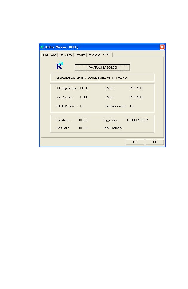
About
The About screen below shows the version information.
There is also a link to our web site.

Wireless LAN 802.11a/b/g USB adapter
1-20
Technical Specifications
Frequency Band
802.11b Radio: 2.412 ~ 2.472 MHz
802.11g Radio: 2.412 ~ 2.472 MHz
USA - FCC 2.412 ~ 2.462 MHz (Ch1~Ch11)
Canada - IC 2.412 ~ 2.462 MHz (Ch1~Ch11)
Europe - ETSI 2.412 ~ 2.472 MHz (Ch1~Ch13)
Japan - STD-T66/STD-33 2.412 ~ 2.484 MHz (Ch1 ~ Ch14)
802.11a Radio: 5.15 GHz ~ 5.85 GHz
USA - FCC 5.15 GHz ~ 5.35 GHz
Canada - IC 5.15 GHz ~ 5.35 GHz
Europe - 5.15 GHz ~ 5.725 GHz
Japan - 4.9 GHz ~ 5.35 GHz
Maximum Channels
IEEE 802.11a/b/g compliant
11 channels (US, Canada)
13 channels (ETSI)
4 channels (France)
14 channels (Japan)
Data Rate
802.11a/g: 6, 9, 12, 18, 24, 36, 48, 54 Mbps per channel
802.11b: 1, 2, 5.5, 11 Mbps per channel
Modulation Type
OFDM, CCK
Operating Frequency
2.4 ~ 2.4835 GHz (US, Canada, ETSI)
2.4 ~ 2.497 GHz (Japan)
Operating Range
100 - 400m, depending on surrounding environment

T
ECHNICAL
S
PECIFICATIONS
1-21
Interface
USB 2.0
Management
Windows-based utility for configuration and status monitoring
Operating System
Windows 98/Me/2000/XP
Dimensions
90 x 35 x 14 mm (3.54 x 1.38 x 0.55 in)
Weight
30 g (0.96 oz)
Security
64/128-bit WEP, WPA, WPA-PSK (TKIP), WPA 802.1X/EAP,
WPA2-PSK (CCMP-AES), WPA2-802.1X/EAP, CCX 2.0
Temperature
Operating 0 to 45 °C (32 to 113 °F)
Storage -25 to 70 °C (-13 to 158 °F)
EMC/Safety Compliances
ETSI/CE
Standards
IEEE 802.11a, b, g
USB 2.0

Wireless LAN 802.11a/b/g USB adapter
1-22
Model Number: WN6501CEP