Seiko Fb 900 Users Manual
FB-900 to the manual 69493b9c-e7c3-4bf0-bc89-f58a2a150082
2015-02-03
: Seiko Seiko-Fb-900-Users-Manual-466948 seiko-fb-900-users-manual-466948 seiko pdf
Open the PDF directly: View PDF ![]() .
.
Page Count: 1
24-pin Dot-matrix Printer
FB-900
OWNER'S MANUAL

1. No part of this manual may be reproduced in any form.
2. This manual is subject to change without notice.
3. This manual was prepared with the greateset care. If you should find any unclear points,
mistakes, or omissions, please contact us.
4. We will not bear any responsibility for unsatisfactory results from the use of this printer
despite item 3 above.
* EPSON is a registered trademark of S.Epson Corporation.
* LQ-2550 is a registered trademark of S.Epson Corporation.
* IBM is a registered trademark of International Business Machines Corporation.
* IBM 2391 is a registered trademark of International Business Machines Corporation.
* HP is a registered trademark of HEWLETT-PACKARD Company.
* PCL is a registered trademark of HEWLETT-PACKARD Company.
* DeskJet 500 / RuggedWriter 480 are registered trademarks of HEWLETT-PACKARD
Company.
* Windows is a registered trademark of Microsoft Corporation.
Copyright © 1999 SEIKO Precision Inc.
Warning
This equipment has been tested and found to comply with the limits for a Class B digital
device, pursuant to Part 15 of the FCC Rules. These limits are designed to provide
reasonable protection against harmful interference in a residential installation. This
equipment generates, uses, and can raditae frequency energy and, if not installed and
used in strict accordance with the instructions, may cause harmful interference to radio
communications. However there is no guaratee that interfernce will not occur in a
particular installation. If this equipment does cause harmful interference to radio or
television recption, which can be determined by turning the equipment off and on, the
user is encouraged to try to correct the interference by one or more of the following
measures:
— Reorient or relocate the receiving antenna
— Increase the separation between the equipment and receiver.
— Connect the equipment into an outlet on a circuit different from that to which the
receiver is connected.
— Consult the dealer ro an experienced radio/TV technician for help.
“It is necessary to use shielded interconnect cables to insure compliance with FCC Class
B limits for radio frequency emissions.”
Caution : Changes or modifications not expressly approved by the party responsible for
compliance could void the user’s authority to operate the equipment.

1. No part of this manual may be reproduced in any form.
2. This manual is subject to change without notice.
3. This manual was prepared with the greateset care. If you should find any unclear points,
mistakes, or omissions, please contact us.
4. We will not bear any responsibility for unsatisfactory results from the use of this printer
despite item 3 above.
* EPSON is a registered trademark of S.Epson Corporation.
* LQ-2550 is a registered trademark of S.Epson Corporation.
* IBM is a registered trademark of International Business Machines Corporation.
* IBM 2391 is a registered trademark of International Business Machines Corporation.
* HP is a registered trademark of HEWLETT-PACKARD Company.
* PCL is a registered trademark of HEWLETT-PACKARD Company.
* DeskJet 500 / RuggedWriter 480 are registered trademarks of HEWLETT-PACKARD
Company.
* Windows is a registered trademark of Microsoft Corporation.
Copyright © 1996 SEIKO Precision Inc.
Warning
This equipment has been tested and found to comply with the limits for a Class B digital
device, pursuant to Part 15 of the FCC Rules. These limits are designed to provide
reasonable protection against harmful interference in a residential installation. This
equipment generates, uses, and can raditae frequency energy and, if not installed and
used in strict accordance with the instructions, may cause harmful interference to radio
communications. However there is no guaratee that interfernce will not occur in a
particular installation. If this equipment does cause harmful interference to radio or
television recption, which can be determined by turning the equipment off and on, the
user is encouraged to try to correct the interference by one or more of the following
measures:
—Reorient or relocate the receiving antenna
—Increase the separation between the equipment and receiver.
—Connect the equipment into an outlet on a circuit different from that to which the
receiver is connected.
—Consult the dealer ro an experienced radio/TV technician for help.
“It is necessary to use shielded interconnect cables to insure compliance with FCC Class
B limits for radio frequency emissions.”
Caution: Changes or modifications not expressly approved by the party responsible for
compliance could void the user’s authority to operate the equipment.
OWNER'S MANUAL
1999 SEIKO Precision Inc.
C
24-pin Wide-Carriage
Dot Matrix Printer
FB-900
As an ENERGY STAR Partner, SEIKO Precision Inc. has determined that this product meets
the ENERGY STAR guidelines for energy efficiency.
- Outline of the International ENERGY STAR Office Equipment Program -
The International ENERGY STAR Office Equipment Program is an international program
that promotes energy saving through the use of computers and other office equipment. The
program backs the development and dissemination of products with functions that effectively
reduce energy consumption. It is an open system in which business proprietors can participate
voluntarily. The targeted products are office equipment such as computers, displays, printers, facsimiles,
and copiers. Their standards and logos uniform among participating nations.

How to use this maunal
This manual describes the operation procedures for the 24-Pin Wide-Carriage Dot
Matrix Printer. Read through this manual before using the printer. Keep this
manual near the printer and refer to it whenever necessary.
Sections 1 and 2 describe the basic procedures, including unpacking, setup and
key operations. Install and setup the printer as described in these sections.
Section 3 and subsequent sections describe the functions and software commands
of the printer. Refer to these sections when necessary.
This manual is organized as shown below.
1. Setting up the printer
2. Control panel operations
3. Setup options
4. Functions
5. Bar code and enlarged character function
6. Troubleshooting
7. Interface specifications
8. Software commands
9. Software setup functions
10. Specifications
11. Character set table
Index
Software command list
Read this manual thoroughly to use the printer properly.
—How to use this manual—
Precautions for use
Organization of this manual
Symbols used in this manual
How to use this maunal
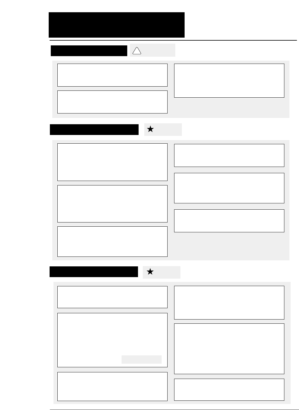
A caution symbol
Care should be taken in order to operate the
printer correctly.
This symbol indicates a note that is useful for
operation.
1.
2.
3.
These item numbers show the sequence of
operation. Perform the operations in the
order shown.
1. MULTIPART
2.HEAD ADJUSTMENT
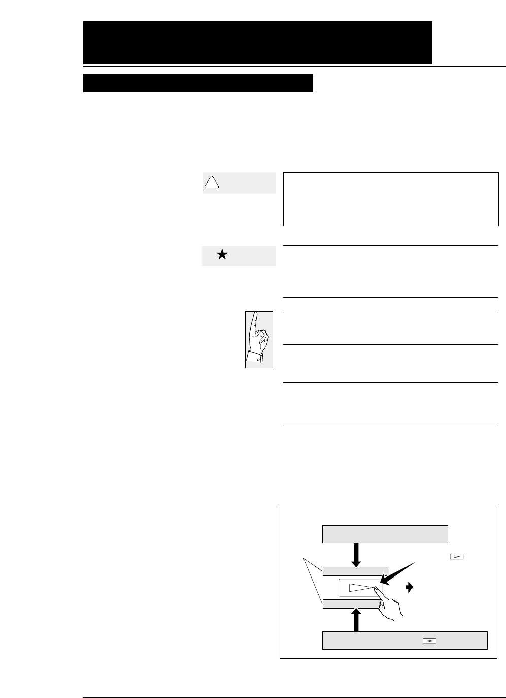
Press the key.
Display on the LCD
To the next step
Display on the LCD before
the key is pressed
Display on the LCD after the key is pressed
The symbols used in this manual have the following meanings.
—How to use this manual—
CAUTION
!
Caution
This symbol indicates that personal injury
may occur if this caution warning is ignored.

Contents
Preface
How to use this manual
Cautions for use
Organization of this manual
Symbols used in this manual
●Major functions..................................... i
●Cautions................................................. iv
Safety Cautions............................
iv
Cautions in setting up..................
iv
Cautions in operation...................
iv
●Unpacking the printer......................... v
Unpacking the printer................. vi
● Dimensions........................................... vii
● Components and functions................ viii
Appearance of the printer...........
viii
Components and functions.........
ix
Operation panel explanation 1.. x
Operation panel explanation 2. xi
Options and consumables....... xii
Maintenance............................ xiii
1. Setting up the printer...................... 1-1
● Connecting the printer to
the power source.................. 1-1
● Installing the ribbon cassette........... 1-2
Installing the ribbon cassette..1-2
● Paper path............................................ 1-4
Path of fanfold paper................ 1-4
Path of cut sheet paper............ 1-5
● Selecting the paper path.................... 1-6
● Paper..................................................... 1-8
● Selecting the paper form..................1-10
● Loading fanfold paper
(Front tractor)
..........................1-12
(Rear tractor)............................ 1-16
● Loading cut sheet paper
(Manual paper feeding)............ 1-19
● Printing using the cut sheet feeder
(Optional).............................1-22
● Running the self-test.......................1-27
● Connecting the printer to
the computer...........................1-28
Parallel interface....................1-28
Serial interface.......................1-29
● Input data hexadecimal dump list...1-30
● Link between paper path (PATH)
and paper form (MEMO)..........1-31
2. Control panel
operations......................... 2-1
● Control panel operations................... 2-1
Control panel............................ 2-1
Fuction keys............................. 2-1
LCD........................................... 2-5
3. Setup options.................................... 3-1
Outline of the
setup modes..... ......3-1
Available function in the
setup modes........... 3-1
Entering the setup
modes.................... 3-1
● Operations on the setup mode...........3-2
Keys for setting......................... 3-2
Setting example in EXTENDED
SETUP MODE.... 3-3
● Setup mode summary (1).................. 3-4
● Setup mode summary (2).................. 3-5
● Factory default setting..................... 3-6
#01 Multipart............................................. 3-8
#02 Head adjustment............................... 3-9
#03 TOF adjustment.............................. 3-10
#04 Page length..................................... 3-11
#05 Paper width..................................... 3-12
#06 Top margin..................................... 3-13
#07 Bottom margin............................... 3-14
#08 Left margin..................................... 3-15
#09 Right margin................................... 3-16
#10 Character quality............................ 3-17
#11 Character font................................. 3-18
#12 Character pitch............................... 3-19
#13 Line feed pitch................................ 3-20
#14 Enlarging/Reducing print.............. 3-21
#15 Paper Fastener................................ 3-22
#16 Perforation...................................... 3-22
#17 Fanfold feed.................................... 3-23
#18 Paper Quality.................................... 3-23
#19 Saving data in format memory...... 3-24
#20 Loading data from format
memory................................ 3-24
#20 Emulation........................................ 3-25
#21 Character table (HP)....................... 3-25
#22 Character table (EPSON)............... 3-26
#23 Character table (IBM).................... 3-26

#24 National font (EPSON).................. 3-27
#25 Code page...................................... 3-28
#26 Alternate graphics mode (AGM)
(IBM).................................. 3-28
#27 CR code function............................ 3-29
#28 LF code function............................ 3-29
#29 Accent character............................ 3-30
#30 Zero font style................................ 3-30
#31 Horizontal tab................................ 3-31
#32 Locking page length...................... 3-31
#33 Locking font................................... 3-32
#34 Locking character pitch................. 3-32
#35 Locking character quality.............. 3-33
#36 Locking character table.................. 3-33
#37 FF code function / TOF ................. 3-34
#38 Graphic Quality.............................. 3-35
#40
Validity of bar code and
enlarged character
................ 3-36
#41
Bar code type
................................... 3-37
Bar code specifications.........
3-38
#42 Bar code size................................... 3-39
#43 Enlarged character size.................. 3-39
#44 Software setup................................ 3-40
#50 PCL mode (HP).............................. 3-40
#51 Secondary character table (HP).... 3-41
#60 Setting option.................................. 3-41
#61 Paper path....................................... 3-42
#62 Automatic scrolling........................ 3-42
#63 Out-of-paper detection.................... 3-43
#64 Skew detection............................... 3-43
#65 Paper jam detection....................... 3-44
#66 Line feed speed.............................. 3-44
#67 Auto scroll position........................ 3-45
#70 Interface.......................................... 3-46
#71 Printer select command................... 3-47
#72 Parity bit (Serial I/F)................... 3-47
#73 Data length (Serial I/F)............... 3-48
#74 Stop bit (Serial I/F)...................... 3-48
#75 Protocol (Serial I/F)..................... 3-49
#76 Baud rate (Serial I/F)................... 3-49
#77 Serial error (Serial I/F)................ 3-50
#78 CTS signal (Serial I/F)................. 3-50
#79 CD signal (Serial I/F)................... 3-51
#80 DSR signal (Serial I/F)................. 3-51
#81 Input buffer size.............................. 3-52
#82 BUSY/ACK signal timing
(Parallel I/F)....................... 3-53
#83 Data latch timing
(Parallel I/F)....................... 3-53
#84 Error Status (Parallel I/F)............... 3-54
#90 Printing direction........................... 3-55
#91 Display language on LCD............. 3-55
#92 Locking panel keys........................ 3-56
#93 Locking reset key........................... 3-56
#94 Printing panel setting..................... 3-57
#95 Printing setup list........................... 3-57
4. Functions........................................ 4-1
● High speed printing............................. 4-1
● Enhancing the copying capability
for multipart forms................. 4-2
● Setting the printing start position........ 4-2
● Feeding perforation to the cutter
position................................... 4-3
● More stable paper feeding.................. 4-3
● Automatically feeding perforation to the paper
cutter position in the standby condition.. 4-4
● EEPROM initialization ...................... 4-5
● Correcting vertical misalignment........ 4-6
● Using various types of paper............... 4-8
● Executing test printing......................... 4-9
● Key shortcut function........................... 4-9
● Setting the application software......... 4-10
● Connecting the printer in the
HP envioronment................. 4-12
5. Bar code and enlarged
character function................. 5-1
● Bar code type.......................................5-1
Outline of bar code function........ 5-1
Makeup of bar code....................... 5-1
Presettable bar code function list.5-2
Bar code command list................. 5-2
(1) Bar code type.......................................... 5-2
(2) Element width........................................ 5-3
(3) Bar code height..................................... 5-3
(4) Setting HRI on and off........................... 5-3
(5) HRI font.................................................. 5-4
(6) Check character.................................... 5-4
Contents

(7) Starting the bar code data sequence.... 5-4
(8) Ending the bar code data sequence.... 5-5
(9) Bar code data sequence......................... 5-5
(10) Printing density.................................... 5-5
(11) Guide bar expansion............................ 5-5
(12) Start and stop characters..................... 5-6
(13) Barcode rotational angle...................... 5-6
(14) Disabling HRI of the start
and stop characters................... 5-6
(15) Value input mode.................................. 5-6
(16) Initializing the bar code mode.............. 5-7
Additional explanation of bar code
commands................................. 5-7
◆
Data processing in the bar
code data sequence................... 5-7
◆
Printing bar codes..................................... 5-8
◆
HRI........................................................... 5-9
◆
Error processing...................................... 5-10
◆
Code 128 subset transition rule............. 5-11
◆
UPC-E conversion rule......................... 5-12
◆
Calculating the check character............ 5-12
◆
Other....................................................... 5-14
◆
Element printing.................................... 5-14
● Enlarged character function........... 5-16
Outline of enlarged character
function................................... 5-16
Enlarged character command list.. 5-16
(1) Executing backspacing......................... 5-17
(2) Executing line feeding.......................... 5-17
(3) Executing form feeding........................ 5-18
(4) Executing carriage return..................... 5-18
(5) Initializing the
enlarged character mode........ 5-18
(6) Arrangement of enlarged characters..... 5-19
(7) Cell magnification for enlarged
characters............................... 5-19
(8) All-character set for enlarged
characters................................ 5-20
(9) Selecting an enlarged character font..... 5-20
(10) Height expansion for enlarged
characters................................ 5-21
(11) HMI for enlarged characters............... 5-21
(12) VMI for enlarged characters............... 5-22
(13) Setting and canceling the enlarged
character mode...................... 5-22
(14) Enlarged character cell offset............ 5-23
(15) Enlarged character pitch.................... 5-23
(16) Enlarged character quality.................... 5-24
(17) Enlarged character rotational angle..... 5-24
(18) Setting and canceling enlarged
character smoothing................. 5-25
(19) Enlarged character top offset............... 5-25
(20) Setting and canceling underlining
of enlarged characters.............. 5-26
(21) Enlarged character widthwise
expansition................................5-26
(22) Horizontal printing position for
enlarged characters.................. 5-27
(23) Vertical printing position for
enlarged characters.................. 5-27
◆
Enlarged character print samples.......... 5-28
6. Troubleshooting............................. 6-1
● Functional error messages................ 6-1
● Operational error messages.............. 6-2
● Troubleshooting................................. 6-6
7. Interface specifications............... 7-1
● Parallel interface................................. 7-1
Input connector......................... 7-1
Pin configuration...................... 7-1
Timing chart.............................. 7-2
Input/output conditions............. 7-2
Signal explanations................... 7-3
Input signals to the printer........ 7-3
Output signals from the printer...7-4
● Serial interface.................................... 7-5
Input connector........................ 7-5
Pin configuration...................... 7-5
Timing chart.............................. 7-5
Input signals to the printer........ 7-6
Output signals from the printer.. 7-7
Contents

Handshaking protocol................ 7-8
DTR (READY/BUSY)
protocol..................7-8
X-ON/X-OFF (I)/(II) protocol. 7-9
Special notes............................ 7-10
ETX/ACK protocol................. 7-11
Baud rate................................. 7-11
Serial data organization........... 7-11
Automatic serial/parallel
selection.......................... 7-11
8. Software commands..................... 8-1
● EPSON Software command........... 8-1
● IBM Software command................. 8-9
● HP Software command.................. 8-18
9. Software setup functions.......... 9-1
● Command format............................... 9-1
● Command............................................ 9-2
10. Specifications................................ 10-1
● Printing specifications.......................10-1
● Print mode specifications.................. 10-2
● Graphic printing specifications.......... 10-5
● Throughput...................................... 10-5
● Paper specifications.......................... 10-6
● Other specifications.......................... 10-6
11. Character set table.................... 11-1
EPSON italic table...................................11-1
EPSON extenced graphic table...................11-1
EPSON international font table.................. 11-2
IBM character set table 1...........................11-2
IBM character set table 2...........................11-3
IBM all-character set table.........................11-3
Code page 437........................................ 11-4
Code page 850........................................ 11-4
Code page 857 ........................................11-4
Code page 860 .......................................11-4
Code page 863........................................ 11-5
Code page 865........................................ 11-5
ISO-1 (ISO-8859-1)..................................11-5
Code page 858.......................................... 11-5
Code page 861.......................................... 11-6
Code page BRASCII.................................11-6
Code page ABICOMP...............................11-6
ROMAN-8 character set (HP)....................11-7
PC-8 character set (HP).............................11-7
LEGAL character set (HP).........................11-7
MATH 7 character set (HP)........................11-7
LINE DRAW character set (HP).................11-8
International character set (HP) [ISO].........11-8
●Index
●Software command list
Contents

i
◆ High-speed printing
Prining mode Pirnt speed Throughput
DRAFT (10 cpi) 603 CPS 206 LPM (132 columns)
LQ (10 cpi) 180 CPS 76 LPM (132 columns)
NLQ (10 cpi) 240 CPS 100 LPM (132 columns)
HQDR (10 cpi) 360CPS 135 LPM (132 columns)
S.D. (12 cpi only) 723 CPS 230 LPM (132 columns)
S.S.D. (15 cpi only) 904 CPS 270 LPM (132 columns)
◆ Original plus 8 multipart forms printing
The printer can print data on an original and up to eight
copies. Copy density can be enhanced by selecting the
DARK 1 (high pressure), DARK 2 (very high pressure) or
AUTO (automatic print pressure adjustment by sensing
the form set thickness). This setting is made in the
MULTIPART function of the SETUP MODE.
✽ : If DARK 1 or DARK 2 is selected, the printing
speed is reduced below the normal print speed
to compensate for the extra energy required
when printing in the high pressure print
modes.
◆ Bar code printing function
A variety of bar codes of this printer may be printed. The
narrow and wide spaces, narrow and wide bars, HRI,
check character, bar code height, and rotation may be
controlled with software commands. Customized bar
codes may also be printed using the element funcion.
Registered bar code formats: Industrial 2 of 5, Interleaved 2
of 5, Matrix 2 of 5, Codabar, Code11, Code 39 , Code 93,
Code 128, EAN-8, EAN-13, UPC-A, UPC-E, and Postnet
◆ Enlarged character printing
Characters can be enlarged (by up to 127 times as large x
127 times as large) using the enlarged character command
unique to this printer. Software commands are used for
control.
●●
Major functions
This printer provides a wide range of print functions, as shown below:

ii
●●
Major functions
◆Zooming function (Batch enlargement or reduction printing)
◆Cut sheet paper manually loading
◆Skew sensor
A built-in skew sensor detects any cut sheets that are
skewed when loaded and ejects them.
◆Automatic head adjustment
The printer employs an automatic paper thickness
detection sensor, instead of the conventional paper
thickness adjust lever, for optimum printing on all form
sets.
◆Automatic loading (For fanfold or cut sheet paper)
◆Perforation cutting (For fanfold paper)
By pressing the TEAR OFF key, the perforation of fanfold
paper is automatically fed to the paper cutter position.
◆Paper parking (Switching fanfold paper and cut sheet paper)
If cut sheet paper is selected while fanfold paper is used,
the fanfold paper is automatically fed back to the parking
position (i.e., paper parking).
◆Load adjustment
The pritning start position may be adjusted within a
range from approximately 0 to 26.7 mm from the top of
the paper. It is recommended that the printing position
be in the center of the paper in the range of 4 mm or less
from the the top of the paper.
◆MICRO REVERSE LF and MICRO LF keys
These keys are useful for adjusting the printing start
position and paper cutting position.
◆Automatic scroll (For fanfold paper)
If no data input is recived for a preset period (0.5, 1, 5,
10, 15 sec.), the perfpration of the current page of fanfold
paper is fed to the paper cutter position.

iii
◆Dual paper parking
If the optional rear tractor is used, two different types of
fanfold paper may be used. Software command or the
PAPER PATH key can be used for selection.
◆Large 512KB communication buffer
◆Setup memory for setting various functions on the LCD
◆Ten resident fonts
◆Line feed speed adjustment
Standard, 1/2 or 1/3 line feed speed is selectable for
stable paper feeding even when multipart paper is used.
◆Vertical alignment function
◆Serial data transfer at a maximum rate of 38.4k bps
◆Parallel and serial interfaces are standard
Parallel and serial interface are switched automatically.
◆Printing stops immediately if the printer cover is
inadvertently opened during printing.
◆Enegy Star
iv
●●
Caution
★Unpack the printer. Make sure that the
printer body and all accessories are
included in the package and no parts are
damaged.
★Do not use the printer in a location
exposed to direct sunlight or close to a
heater or other heat generating
equipment.
★Before connecting or disconnecting the
interface cable, be sure to turn off the
printer.
★ Place the printer on a rigid, horizontal
base in a location that is free of vibration.
★Do not use the printer in a dusty location
or any location subject to sudden
changes in temperature and humidity.
★Do not connect the printer to a non-
standard power source.
★ Never try to print without a ribbon
cassette installed and paper loaded.
★Do not turn off the printer during
printing, as this may lead to a
malfunction.
★Take care not to twist the ribbon while
installing the ribbon cassette.
★Push the lock levers of both tractors
to the LOCK positions firmly while
loading fanfold paper or single sheet
paper. It is for the purpose of
setting paper path securely.
★If the case or cover becomes dirty,
clean it with a soft cloth moistened
with a small quantity of neutral
detergent diluted with water. Never
use a hard cloth or volatile solvent
such as alcohol, thinner, or benzine.
★If any foreign matter gets into the
printer, turn off the printer
immediately and remove the foreign
matter.
Cautions in operation
Safety Cautions
Cautions in setting up
See page 3-1.
CAUTION
!
Caution
Caution
★Use two hands and hold firmly at each
end when lifting the cut sheet feeder.
Personal injury can occur if the CSF unit
is dropped.
★Do not touch the print head immediately
after printing because it is too hot.
★Do not put your finger under the tractor
cover while loading fanfold paper.
v
●
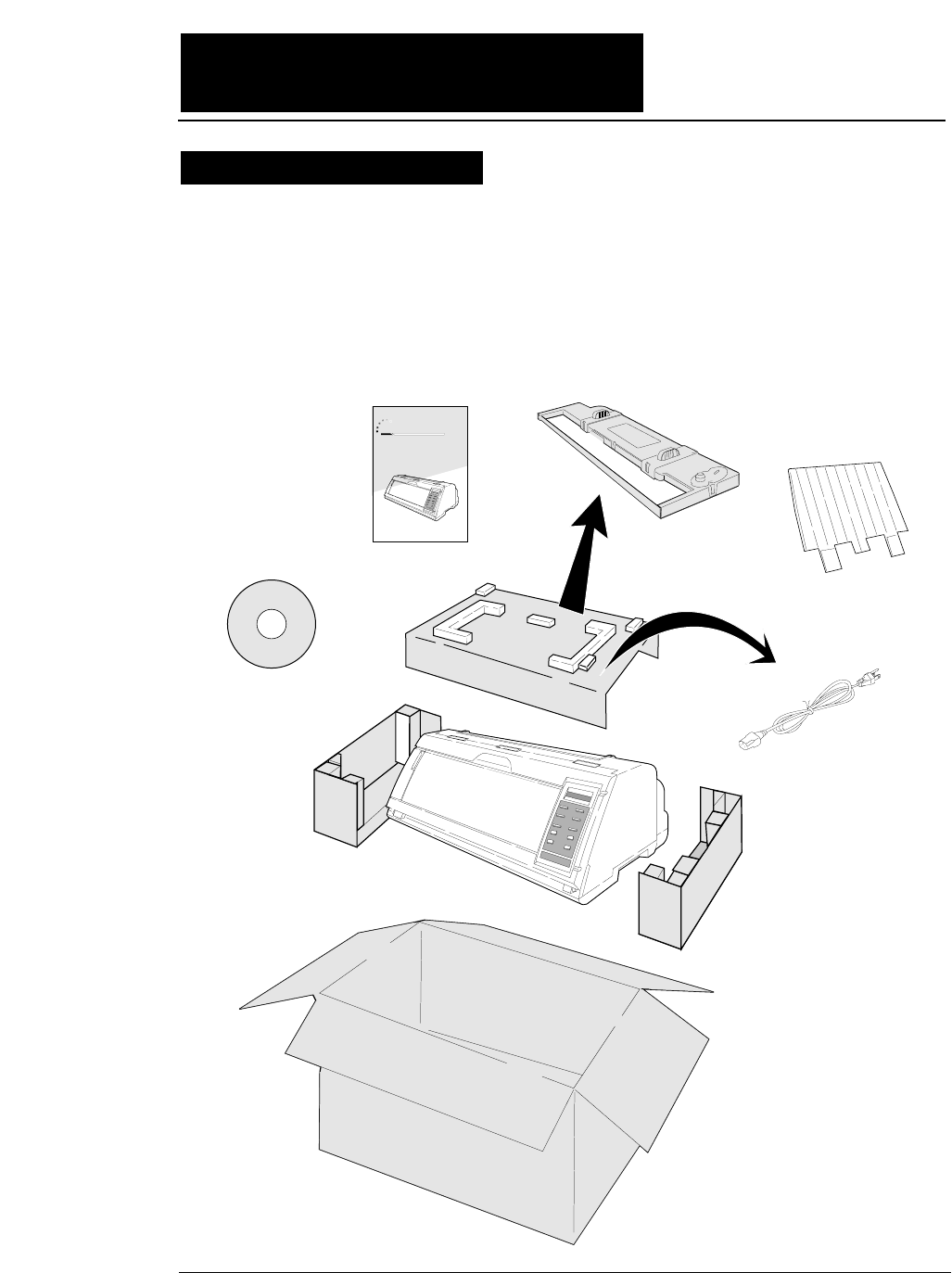
The printer body weights approximately 24 kg [52.9 lbs.]. It should be
taken out of the package by two or more persons.
Make sure that no parts of the printer are damaged.
●●
Unpacking the printer
Printer
Ribbon Cassette
Power Cord
24-pin Dot-matrix Printer
FB-900
Hand book
CD-ROM
Hand book
Top Paper Rack
Unpacking the printer
vi
●●
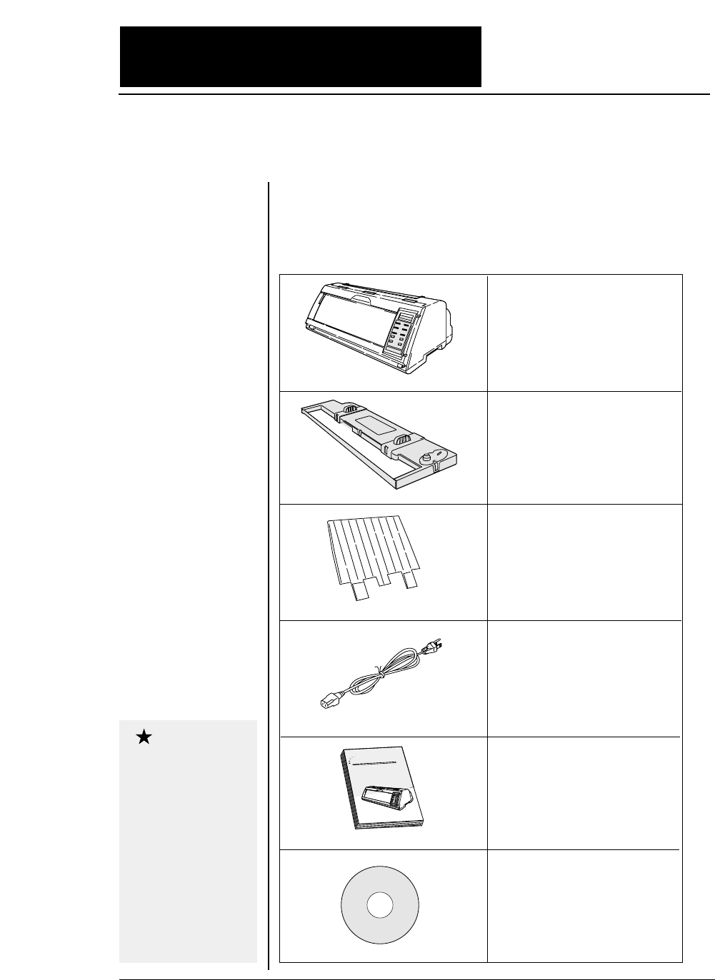
Unpacking the printer
●
Check the carton for the following items:
24-pin Dot-matrix Printer
FB-90
0
Hand book
■
Printer
■
Ribbon cassette
#SBP-1051
■
Power cord
Connect this power cord to an
AC outlet.
If some part is not
included in the package,
contact the dealer where
you purchased the
printer.
Keep the carton and
packaging material.
They are needed for
transporting the printer
or returning it for
service if ever required.
■
Top paper rack
Attach the top paper rack to
eject paper to the top of the
printer. Sheets of paper are
stacked on this rack.
Caution
■
Hand book
■
CD-ROM
Driver-CD with Owner's
Manual, printer driver
software.
vii
●●
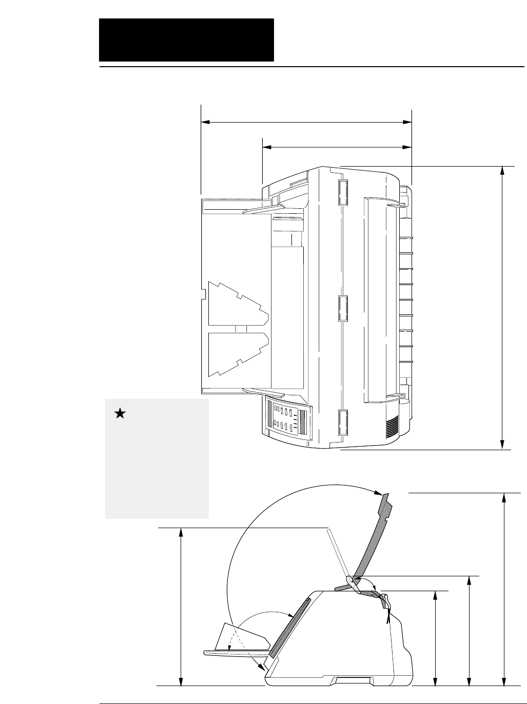
Dimensions
●
The following drawings show the outside dimensions of the printer.
300mm
250mm
520mm 630mm
505mm
395mm
442mm
The weight of the
printer including the
ribbon cassette is
approximately 24 kg
[52.9 lbs.]. Two
persons should carry
the printer.
Caution
viii
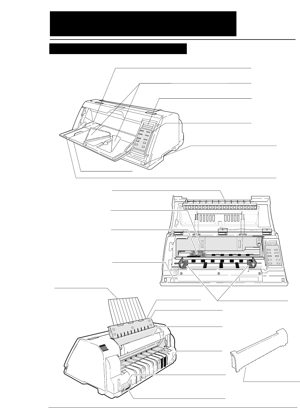
●●
Components and functions
1
1. Paper Guide (for Manual Feeding)
2. Paper Stacker (for Cut Sheet Feeder)
3. Liquid Crystal Display (LCD)
4. Control Panel
11. Power Switch
16. AC Receptacle
17. Serial Connector
18. Parallel Connector
12. Tractor
19. Rear Printer Cover
14. Top Cover
LCD: TOP COVER
5. Paper Rack
LCD: PAPER RACK
15. Rear Cover
LCD: REAR COVER
13. Top Paper Rack
8. Front Cover
LCD: FRONT COVER
10. Print Head
9. Ribbon Cassette
6. Paper Support Guide (for Manual Feeding)
20. Paper Cutter
7. Front Cover Lock Release Button
Appearance of the printer
ix
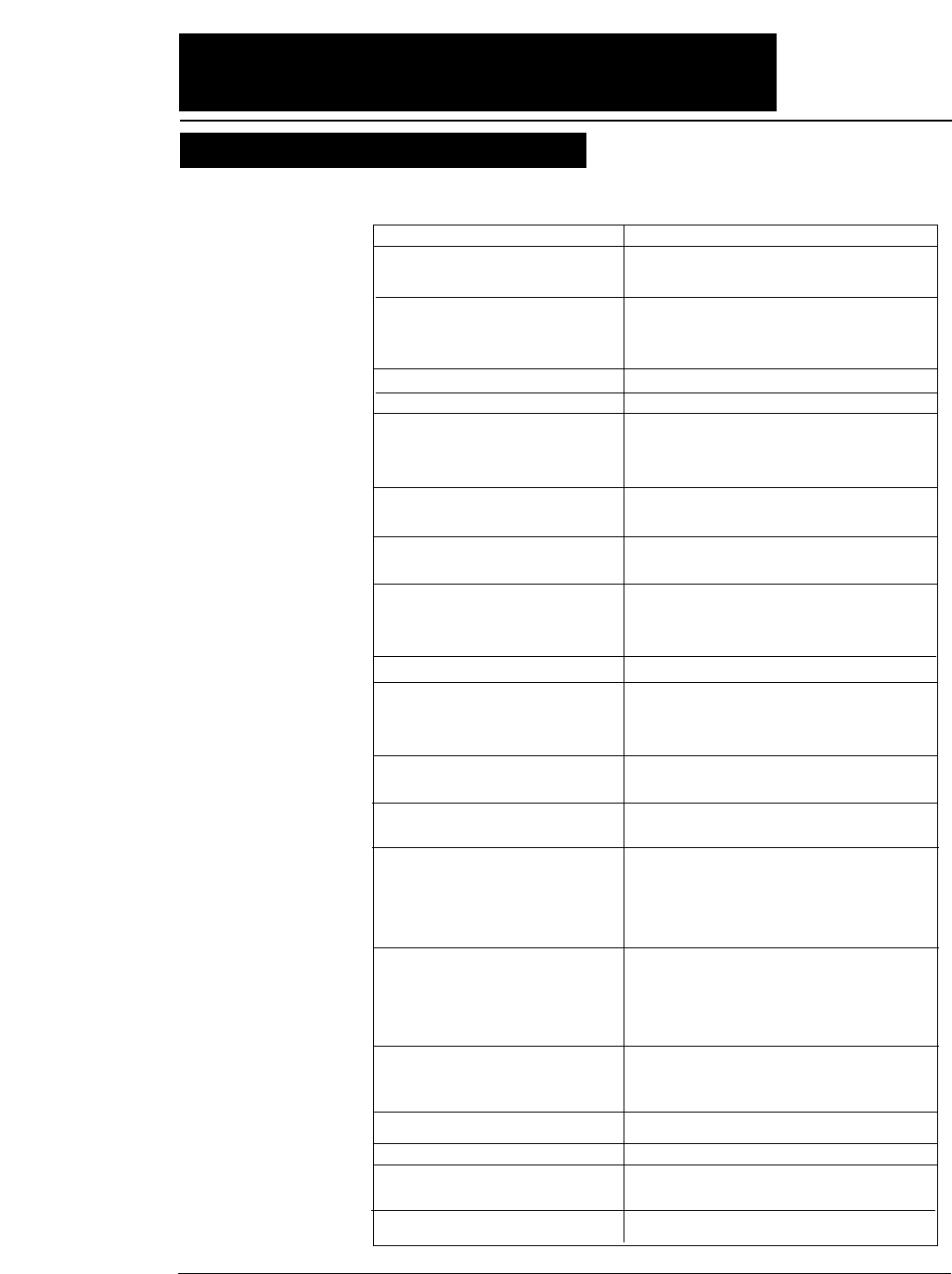
The names and functions of the printer components are shown below.
Name (See drawing on left.) Function
1. Paper guide Adjusts the printing position when feeding paper
manually.
2. Paper stacker When the optional CSF is used, sheets of paper
are ejected into this paper stacker. Both sides of
the paper stacker should be set up.
3. Liquid crystal display (LCD) Displays the condition and settings of the printer.
4. Control panel Displays and sets the printer conditions.
5. Paper rack If the “OPEN PAPER RACK” message is
desplayed on the LCD when setting the paper
path, open the paper rack.
6. Paper Support Guide Guide the cut sheet at manuarl feeding.
7. Front Cover Lock release button To open the front cover, push the two buttons
located on the lower corners of the front cover.
8. Front cover To mount fanfold paper on tractors or replace the
ribbon cassette, open the front cover.
9. Ribbon cassette If printed characters vecome pale, replace the
ribbon cassette.
10. Print head Prints characters on paper.
11. Power switch Pressing the power switch toggles the power on
and off.
ON: Switch depressed OFF: Switch released
12. Tractor The tractor pins engage sprocket holes on both
sides of fanfold paper for feeding.
13. Top paper rack Ejected cut sheets are stacked on the top paper
rack.
14. Top cover Eject fanfold paper to the top of the printer. If
the “OPEN TOP COVER” is displayed on the
LCD when setting the paepr path, open the top
cover.
15. Rear cover To eject fanfaold paper to the top of the prieter,
open the rear cover. If the “OPEN REAR
COVER” is displayed on the LCD when setting
the paper path, open the rear cover.
16. AC receptacle Connect the power to this AC receptacle. The
power is desigated on the rating plate on the back
of the printer.
17. Serial connector RS-232C interface connector
18. Parallel connector Parallel interface connector
19. Rear printer cover When the rear tractor or CSF is used, remove the
rear printer cover.
20. Paper Cutter Cut the paper after pressing the TEAR OFF key.
●●
Components and functions
Components and functions
x
●●
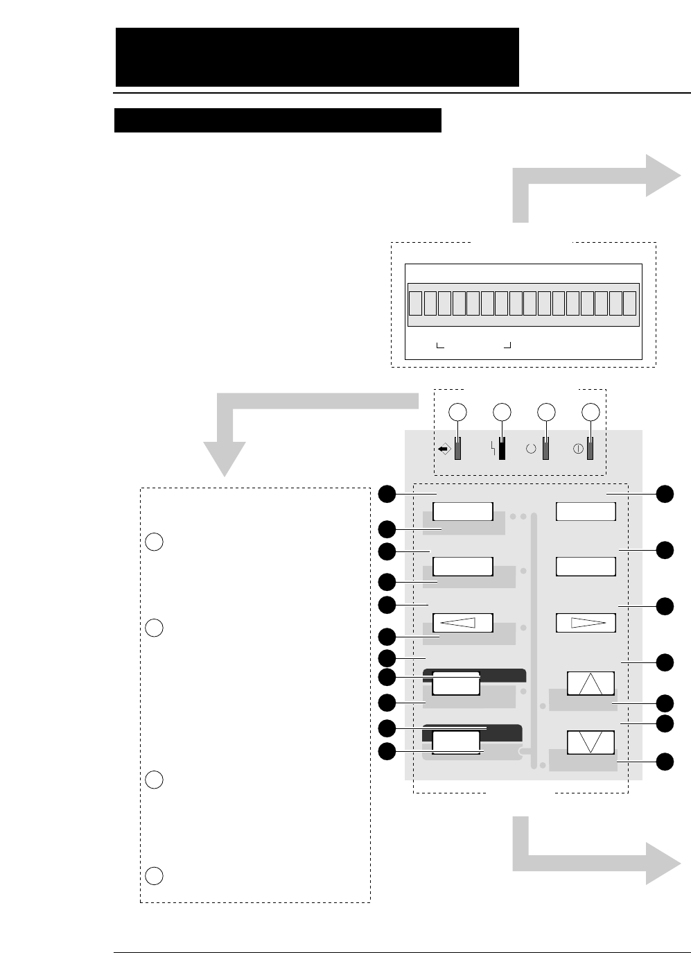
Components and functions
Control panel explanation 1
DATA ERROR ONLINE POWER
TEAR OFF ONLINE
PAPER PATH
FORM FEED
LINE FEED
REVERSE LF
TOF SET
QUALITY
EJECT/LOAD
PAPER FORM
RESET
SET UP
MICRO LF
MICRO RLF
EXIT
EXTENDED
ENTER
ALT
FORM
1.5
x
IN OUT
PAPER PATH
F.TR REAR
1
2
3
4
5
6
11
12
13
14
15
16
17
18
7
9
8
10
1234
State display Lamps
State display LCD
Key Panel
Blinks while data is transferred.
Lights while data is processed except
during communication or when the
input buffer contains data. Goes out
in other conditions.
ON : Paper is not detected some
other operational error has
occurred.
OFF : Paper is detected.
Blinking : A functional error (such
as home sense error,
internal RAM error,
paper path switching error,
head adjustment error,
park error and skew error)
ON : Printing is enabled.
OFF : Printing is disabled.
Blinking : The cover is open, or
the printer is in the head
temperature protect
condition.
On when printer power is turned on.
State display lamps
1
2
3
4
115
xi
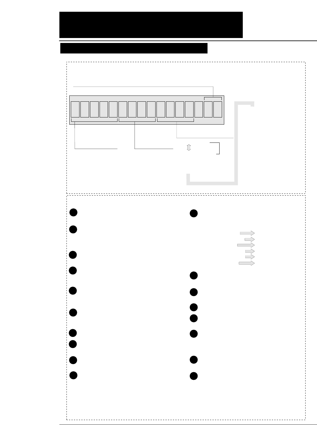
●●
Components and functions
.5x15F.TR REAR 1
F. TR
R. TR
MAN
CSF
: Front Tractor
: Rear Tractor
: Manual
: Cut Sheet Feeder
REAR
TOP
FRNT
: Rear
: Top
: Front
1inch=25.4mm
Paper In Paper Out
15: 15 inches 12: 12 inches 10: 10 inches 5: 5 inches
Paper Width (Fanfold Paper)
2
16.5
A3
A4
A5
Page Length (Fanfold Paper)
Paper Size (Cut Sheet Paper)
: 2 inches
: 16.5 inches
: A3
: A4
: A5
LT
HLT
LG
EX
GLT
GLG
LD
F4
PC
C6
C10
MN
DL
C5
: LETTER
: HALF LETTER
: LEGAL
: EXECUTIVE
: GOVERNMENT LETTER
: GOVERNMENT LEGAL
: LEDGER
: F4 SIZE
: POST CARD
: COMMERCIAL-6
: COMMERCIAL-10
: MONARCH
: DL Envelope
: C5 Envelope
Feeds the perforation of fanfold paper to the paper
cutter poistion. (For fanfold paper only)
(ALT + TEAR OFF keys)
Press these keys for two seconds or more. Release
the keys when "INITIAL" is displayed on the LCD.
The printer will be reset.
Changes the paper path display. To select the
displayed paper path, press the ENTER key.
(ALT + PAPER PATH keys)
When paper is loaded, the current printing position is
considered as the TOF position.
Loads paper or feed back paper to the parking
position when fanfold paper is used. Loads or
and ejects paper when cut sheet paper is uesd.
(ALT + EJECT/LOAD keys)
Changes the printing quality display. To select
the displayed mode, press the ENTER key.
Enters the SETUP MODE.
Quits the SETUP MODE or EXTENDED
SETUP MODE.
(ALT + SETUP keys)
Enters the EXTENDED SETUP MODE.
Selects an item displayed in the SETUP MODE,
the EXTENDED SETUP MODE, setting the
paper path, setting the paper form or setting the
printing quality.
1
2
3
4
5
6
10
11
12
13
14
15
16
17
7
9
8
When pressing the corresponding key while you
press the ALT key, one of the following
functions is executed.
Changes the printing enable (online) state and
printing disable (offline) state.
Changes the paper form display. To select the
displayed paper form, press the ENTER key.
Feeds one page.
Feeds one line in the forward direction at a pitch
of 1/6 inch.
(ALT + LINE FEED keys)
Feeds one line in the forward direction at a pitch
of 1/360 inch.
(Micro line feed)
Feeds one line in the reverse direction at a pitch
of 1/6 inch.
(ALT + REVERSE LF keys)
Feeds one line in the reverse direction at a pitch
of 1/360 inch.
(Micro reverse line feed)
18
State display LCD
Keys on the panel
LINE FEED
REVERSE LF
SET UP
EJECT/LOAD
PAPER PATH
TEAR OFF
MICRO LF
MICRO RLF
EXTENDED SETUP
QUALITY
TOF SET
RESET
1
Orientation (Cut Sheet Paper) p: Portrait l: Landscape
Page
Length
Control panel explanation 2
xii
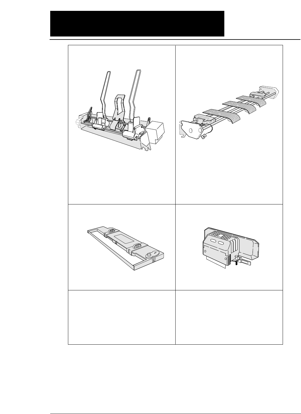
#FB-84008
Cut sheet feeder Rear tractor
For attaching the cut sheet feeder,
see pages 1-22 to 1-26. For attaching the rear tractor, see pages 1-16 to 1-18.
Print head
#FB-90090
For mounting the print head, refer to the manual
supplied with the print head.
Ribbon cassette
#SBP-1051
For attaching the ribbon cassette,
see pages 1-2 and 1-3.
Current loop interface unit
RS-422A interface unit
#FB-84011#FB-84010
#FB-84009
This unit enables data to be transferred through
an RS-422A interface. This is a built-in unit
that is installed by the dealer. If the RS-422A
interface unit is installed, the RS-232C
interface cannot be used.
This unit converts serial data into 20 mA
current loop signals. This is a built-in unit that
is installed by the dealer. If the current loop
interface unit is installed, the RS-232C
interface cannot be used.
The cut sheet feeder feeds cut sheets automatically
and continuously. A maximum of 150 sheets of
paper (55 kg paper) may be set in the holder of the
cut sheet feeder.
Dual paper parking is available when the rear
tractor is used. Two different types of paper may
be set onto the front and rear tractors and may be
selected by issuing software commands or
pressing the PAPER PATH key to change the
paper paths.
●●
Options and consumables
xiii
●●
Maintenance
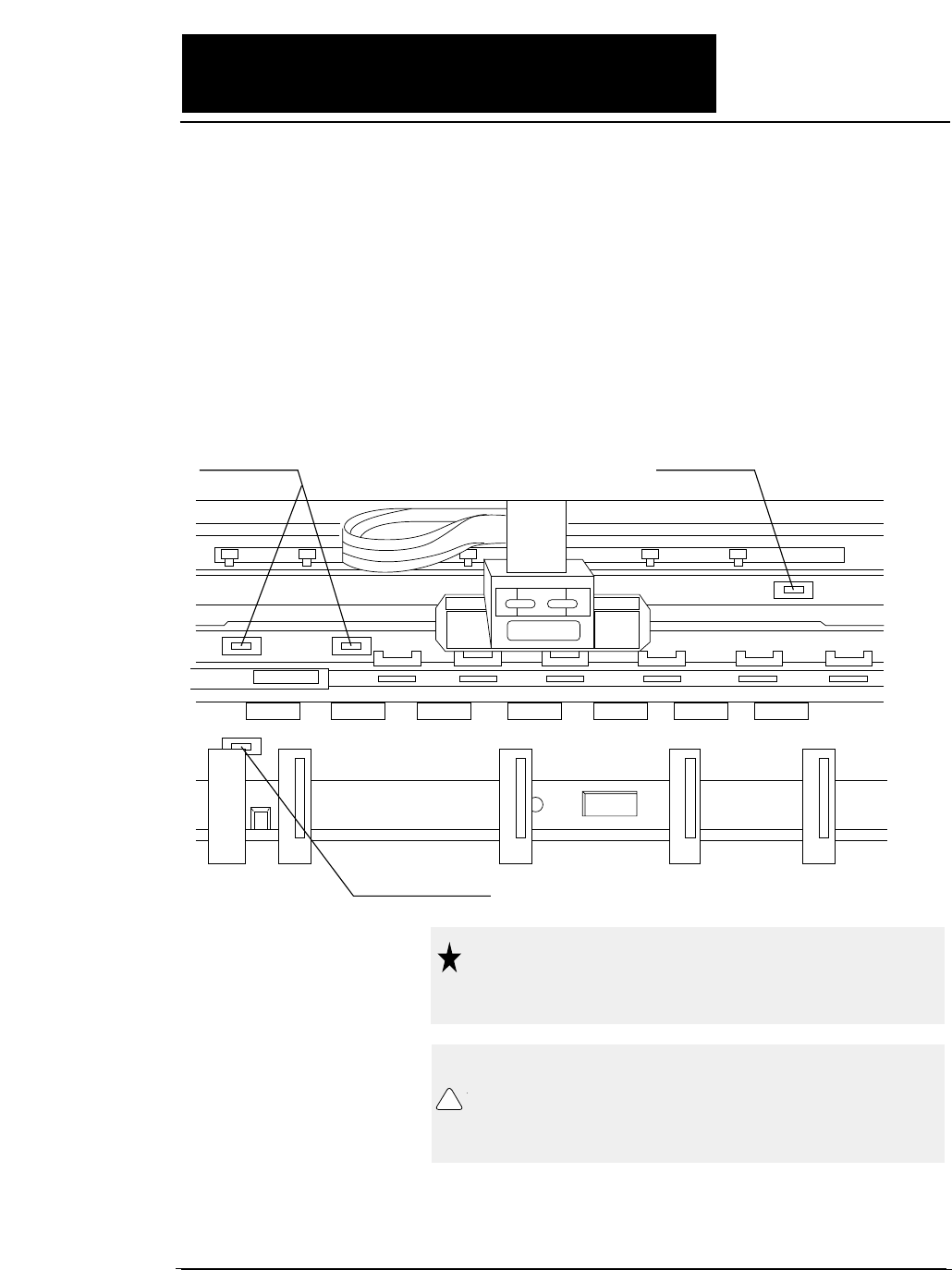
Periodic maintenance and inspection is recommended to keep
the printer in good condition.
●
Remove paper particles or dust adhered to
the detection sensor cover upper surfaces
(three locations) inside the printer and to the
paper jam sensor surface (one location), by
wiping with a soft clth or a cotton bud. The
paper particles or dust on the sensor
surfaces may cause faulty operation.
Detection sensor Detection sensor
Paper jam sensor
Do not use a hard brush to clean the
sensor cover and the sensor surface.
The brush may scratch the surface.
Caution
When opening the front cover just
after the printer has been in operation,
do not touch the printer heard which
is hot and may cause burns.
Caution
!
1-1
—1. Setting up the printer—
1. Setting up the printer
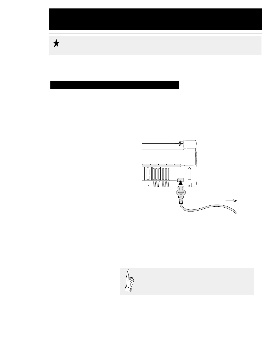
●
Make sure that the power switch is set to off.
Connect the printer with the supplied power
cord to an AC outlet.
●
The AC outlet shall be installed near the
printer and shall be easily accessible.
To AC outlet
Connect the AC power plug to an AC outlet of the voltage
designated on the rating plate on the back of the pirnter.
Once the printer is turned off, wait for three seconds or
more before turning it on again. If the printer is turned
on again within three seconds after turning it off, it
may malfunction due to an initializtion failure.
Caution
●●
Connecting the printer to Power
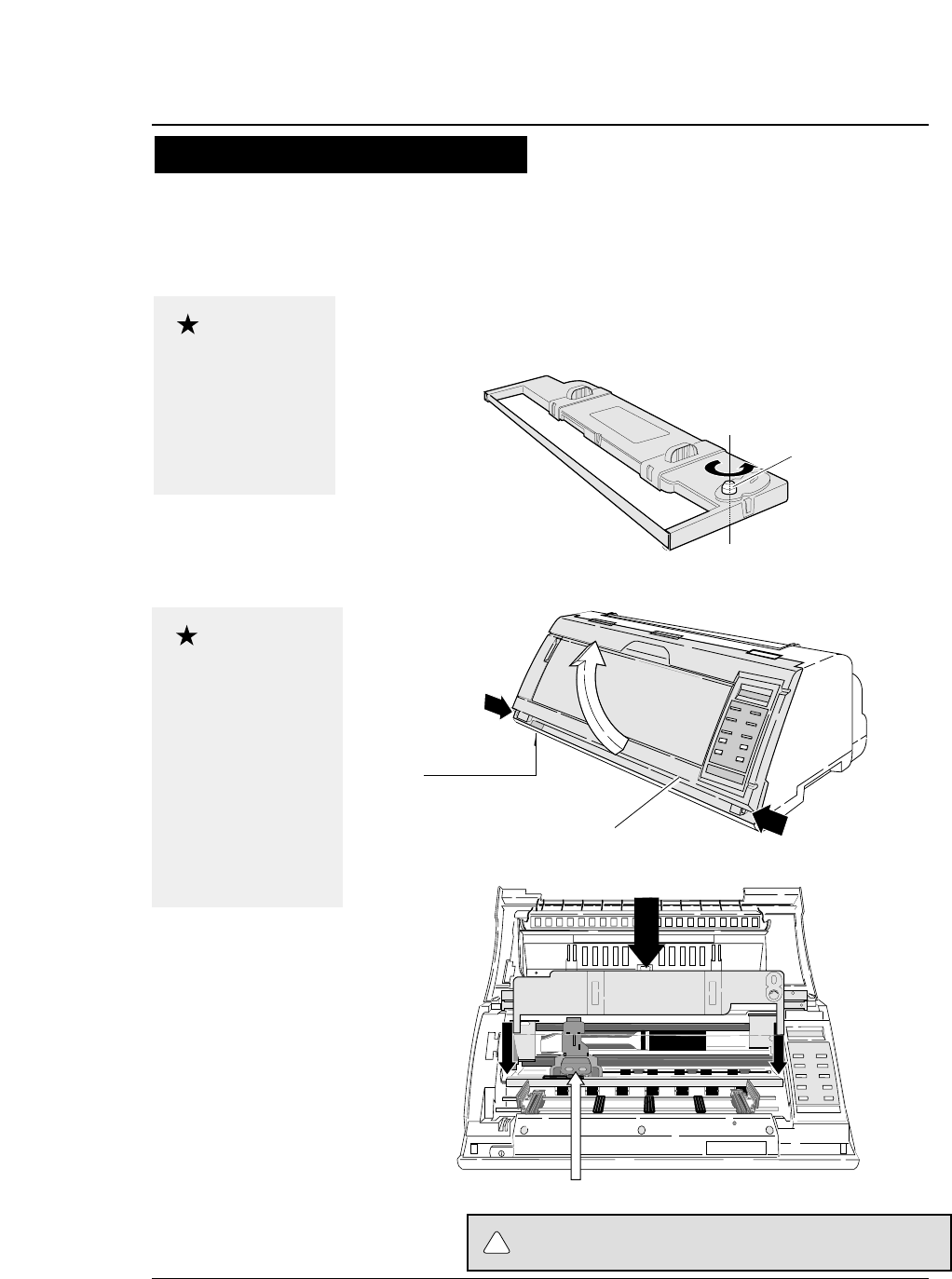
1. Turn the ribbon feed knob on the ribbon
cassette counterclockwise to stretch the
ribbon tight.
2. Turn off the power. Open the front cover.
3. Attach the ribbon cassette as shown below.
1-2
Do not touch the print head immediately
after printing becouse it is too hot.
Use the specified
ribbon cassette .
When power is turned
off, data in the buffer
is lost. Output all data
before turning off the
printer.
Open the front cover by
pressing both side locks
with both hands. Hold
both sides with both
hands to raise it upward
slowly. When closing
the front cover, hold
both sides with both
hands to pull it down
slowly. Press the front
cover to lock it.
Stretch the ribbon
Ribbon feed knob
Installing the ribbon cassette
Approximately 15 seconds after the printer is rutned on, the print head will move to
the left.
Print head position
Front cover
Power switch
Every press of the power
switch turns the power on
or off.
—1. Setting up the printer—
●
Installing the ribbon cassette
Caution
Caution
CAUTION
!
1-3
●
Installing the ribbon cassette
—1. Setting up the printer—
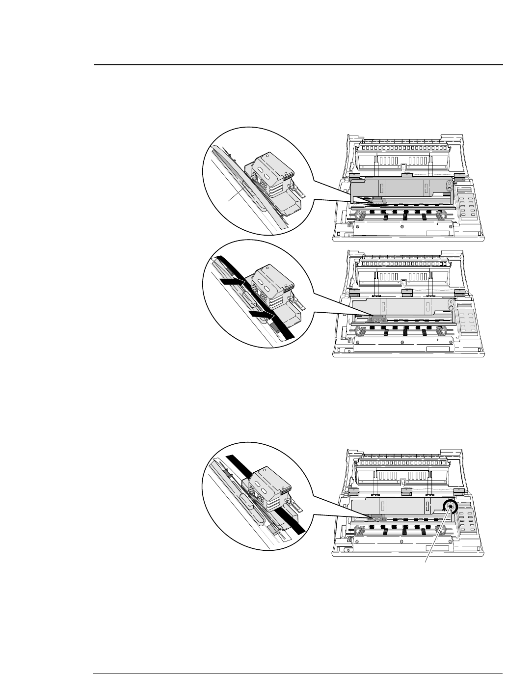
4. Slide the ribbon toward the print head so
that the ribbon is lightly in contact with the
projection of the print head.
5. Attach the cassette firmly to the mounting
plate. Turn the ribbon feed knob
counterclockwise.
Fit the right and left projections on the mounting plate to the holes in
the bottom of the ribbon cassette.
6. Close the front cover.
Pull down the front cover slowly toward you with both hands from
both sides to close it.
Push down on both sides at the bottom of the front cover to close it
firmy. Two hands are required to engage and lockthe front cover on
both sides.
Slide
Slide
Projection
Ribbon feed knob
1-4 —1. Setting up the printer—
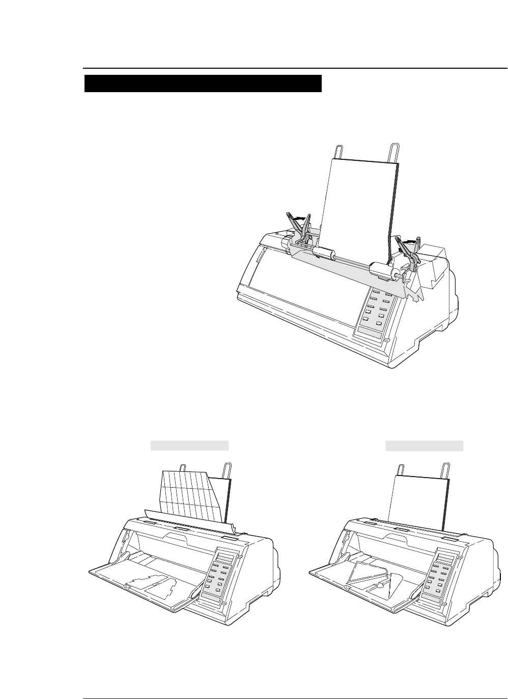
●
Paper path
1
2
Paper loading direction
Rear tractor
(Optional)
Paper loading
direction
3
Paper rack
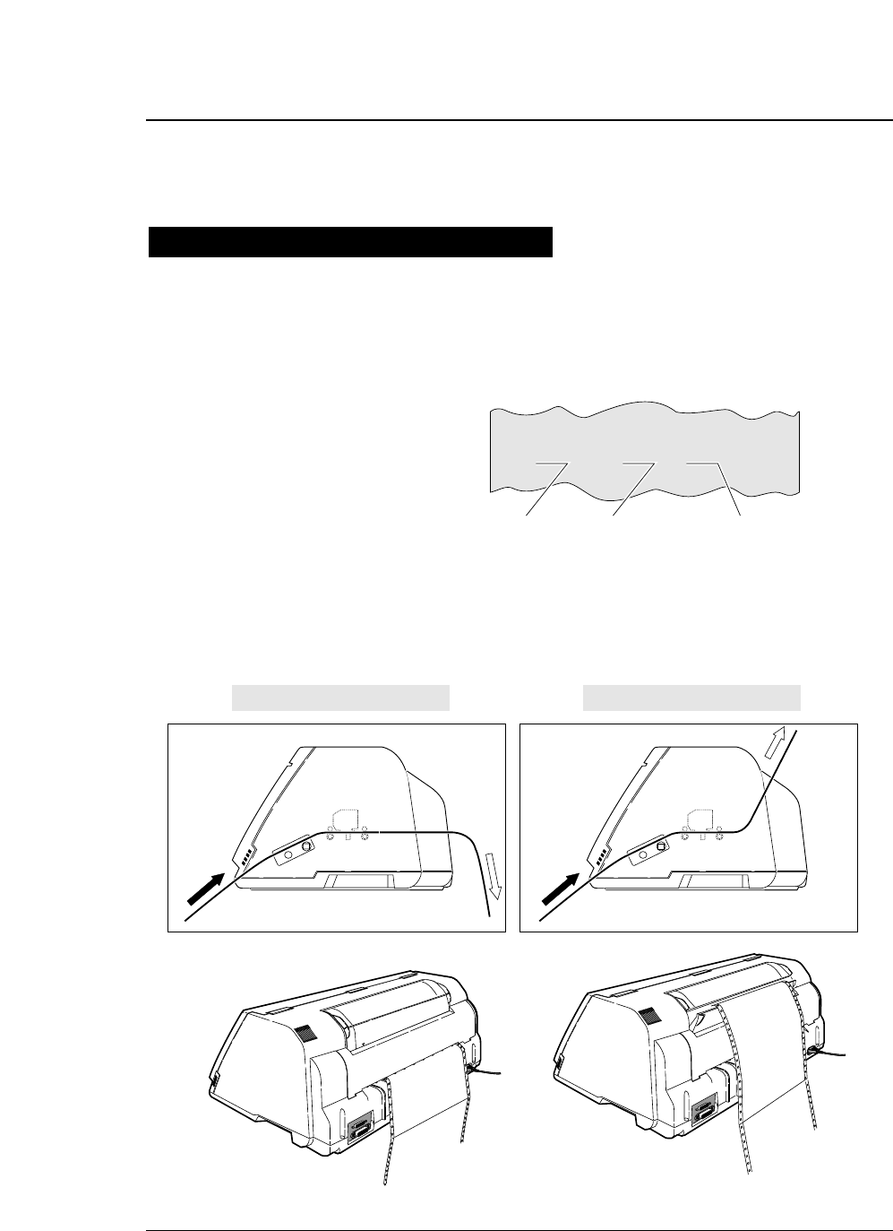
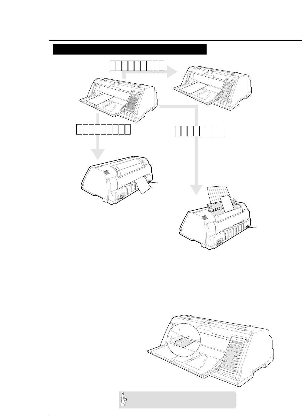
2. Front loading, top ejection
This paper path applies a smaller load to the paper.
This is recommended for printing on thick paper
(such as multipart paper or label sheets).
1. Front loading, rear ejection
This paper path is recommended if fanfold paper is
cut along the perforation frequently.
The perforation is automatically fed to the paper
cutter of the top cover by pressing the TEAR OFF
key so that the paper may be torn off easily.
To cut the paper, hold the upper cover firmly with
one hand and tear the paper towards you.
3. Rear loading, front ejection
Dual paper parking is available when the optional
rear tractor is used. Two types of fanfold paper of
different size and thickness may be used and
selected from the control panel or by issuing a
software command (ESC EM or software setup*)
from the computer.
* Software setup commands
The software setup commands are unique to this
printer. Most functions available on the SETUP
MODE and EXTENDED SETUP MODE can may
11x 5F.TR REAR
11x 5FTRTOP
11x 5R.TR FR T N
Liquid crystal display
Inside of the printer viewed
from the right.
✩
Inside of the printer viewed
from the right.
✩
.
1
1
1
Path of fanfold paper
The three fanfold paper paths shown below are available. For selecting a paper
path, See pages 1-6 and 1-7.
Rear tractor (Option)
Front tractor
1-5
—1. Setting up the printer—
●
Paper path
Path of cut sheet paper
The five cut sheet paper paths shown below are available.
1. Front loading, front ejection
This paper path applies a lighter load on feeding paper. This
is recommended for printing on thick paper (such as
multipart paper, postcards, and envelopes).
3. Front loading, top ejection
This paper path enables face-down stacking.
1
3
2
Paper loading
direction
4. CSF loading, front ejection
This paper path is suitable for thick paper (such as multipart
paper, postcards and so on). Sheets of paper are stacked face-up.
5. CSF loading, top ejection
This paper path enables face-down stacking.
Paper loading
direction
4
5
A4 pMAN F RN T
A4 pMAN REAR
A4 pMAN TO P
A4 pCSF FR
A4 pCSF TOP
Inside of the printer
viewed from the right.
✩
✩
This paper path applies a lighter load on feeding paper. It is
recommended for printing on thick paper (such as multipart
paper, postcards, and envelopes).
NT
2. Front loading, rear ejection
Inside of the printer
viewed from the right.
Manual paper feeding
Cut sheet paper (Option)
●Sheets of paper are loaded manually one at a time.
1-6 —1. Setting up the printer—
●
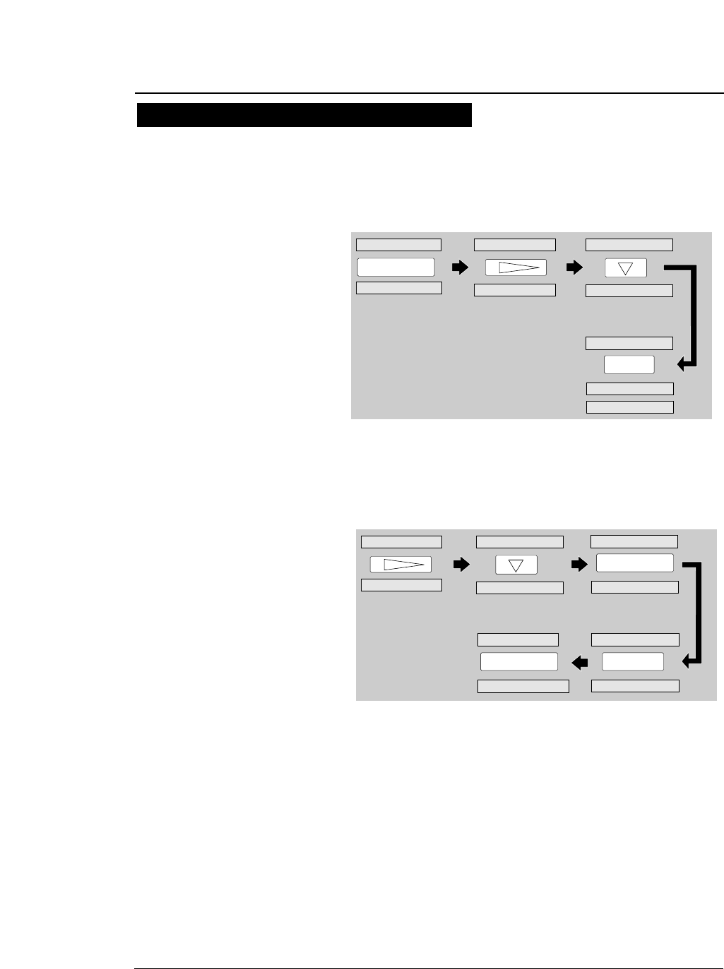
Selecting the Paper path
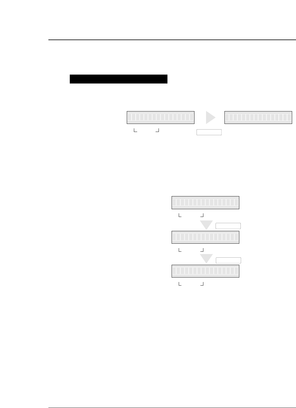
1. Press the PAPER PATH key.
The paper path currently selected is displayed.
2. Continue to press the PAPER PARH key until
“PATH: F. TR. -> TOP ” is displayed. Press
the ENTER key.
Selecting the paper path
The following shows an example of changing the paper path for reference. The
example shown below changes front tractor loading and rear ejection to the front
tractor loading and top ejection.
11x 5
F.
TR EA
IN OUT FORM
PAPER PATH
>
RE
T
F
-APH
.T
RA
PAPER PATH
R
.:
1RR
PAPER PATH
ENTER
IN OUT
PAPER PATH
FORM
11x 5F
.
RT
IN OUT
PAPER PATH
FORM
IN OUT
PAPER PATH
FORM
1
MEM 1F.R->R ATERO
MEM 1F.R->T PTO
->T PO
O
1-7
—1. Setting up the printer—
●
Selecting the paper path
1
1
AAAAAAAAAAAAAAAA
AAAAAAAAAAAAAAAA
AAAAAAAAAAA
AAAAAAAAAAAAAAAA
AAAAAAAAAAAAAAAA
AAAAAAAAAAAAAAAA
AAAAAAAAAAAAAAAA
AAAAAAAAAA
AAAAAAAAAAAAAAAA
AAAAAAAAAAAA
AAAAAAAAAAAAAAAA
AAAAAAAAAAAAAAAA
AAAAAAAAAAAAAAAA
1
1
aaaaaaaaaaaaaaaaa
aaaaaaaaaaaaaaaaa
aaaaaaaaaaaaaaaaa
aaaaaaaaaaaaaaaaa
aaaaaaaaaaaaaaaaa
aaaaaaaaaaaaaaaaa
aaaaaaaaaaaaaaaaa
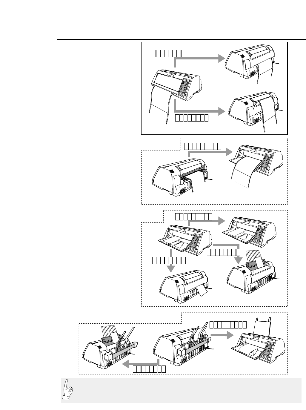
◆Cut sheet paper (Manual feeding)
◆Fanfold paper
1
1
◆Cut sheet paper (Optional cut sheet feeder)
1
◆Fanfold paper (Optional rear tractor)
LOAD
EJECTION
LOAD
EJEC-
TI
ON
EJEC-
TIO
N
LOAD
EJECTION
EJECTION
EJECTION
LOAD
EJECTION
EJEC-
TION
F
.
TR REA
F
.
TR TOP
R
.
TR FRN
MAN F RN
MAN R EA
MAN TOP
CSF TOP
CSF FRN
EJEC-
TION
R
T
T
R
T
AAAAAAAAAAAA
AAAAAAAAAAAAAAAA
AAAAAAAAAAAA
AAAAAAAAAAAAAAAA
AAAAAAAAAAAA
AAAAAAAAAAAAAAAA
AAAAAAAAAAAA
AAAAAAAAAAAAAAAA
The optional CSF and rear tractor cannot be used together. If the optional CSF or rear tractor is
installed, enable it by using the EXTENDED SETUP MODE (#60 option). If the option is not
enabled on the EXTENDED SETUP MODE, the paper path cannot be selected.
1-8 —1. Setting up the printer—
●
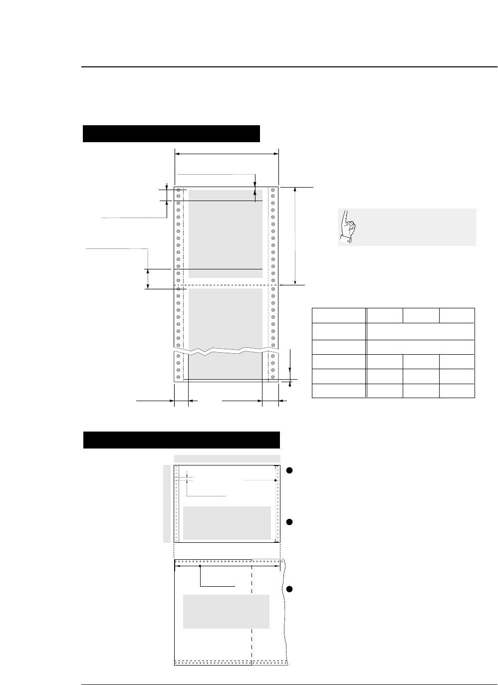
Paper
16 mm or more
0/60 inch - 63/60 inches
(#3 TOF ADJUSTMENT on SETUP
MODE)
2 mm
Printing area
Printing area
5, 10, 15 inches
(#5 PAPER WIDTH on SETUP MODE)
Perforation
2.5 - 16.5 Inches
(#4 PAGE LENGTH on SETUP MODE)
0/6 inch - 15/6 inches
(#6 TOP MARGIN on SETUP
MODE)
0/6 inch - 15/6 inches
(#7 BOTTOM MARGIN on
SETUP MODE)
Last page
Paper form Multipart
form
Rear tractor 3 ~ 16.5 inches (76 ~ 420mm)
19 or less 1
0.08
~ 0.12mm
55 ~ 90kg 34kg x 9P
0.12
~ 0.59mm 0.12
~ 0.18mm
125kg or less
Front tractor 3 ~ 16 inches (76 ~ 406mm)
Paper width
Number of sheets
Thickness
Paper weight
16 mm or more
Label
form
Single
Paper quality Wood-free paper
22 holes
Page length
0.5 inch × 22 = 11 inches
0.5 inch
30 holes
Page width
0.5 inch × 30 = 15 inches
Page length
Paper width
Sprocket holes are made on both sides
of fanfold paper at an interval of 0.5
inch, which can be used to calculate
the page length and width.
The page length can be determined by
multiplying the number of sprocket
holes per page by 0.5 inch.
To find the paper width, use another
sheet of fanfold paper and count the
number of sprocket holes.
Printing area on fanfold paper
Calculating sizes of fanfold paper
Sizes of fanfold paper are
generally shown in inches.
One inch is 25.4 mm.
When fanfold paper is used, set the page length (#4 PAGE LENGTH) and paper
width (#5 PAPER WIDTH) on the SETUP MODE. For setting, see page 1-12.
1-9
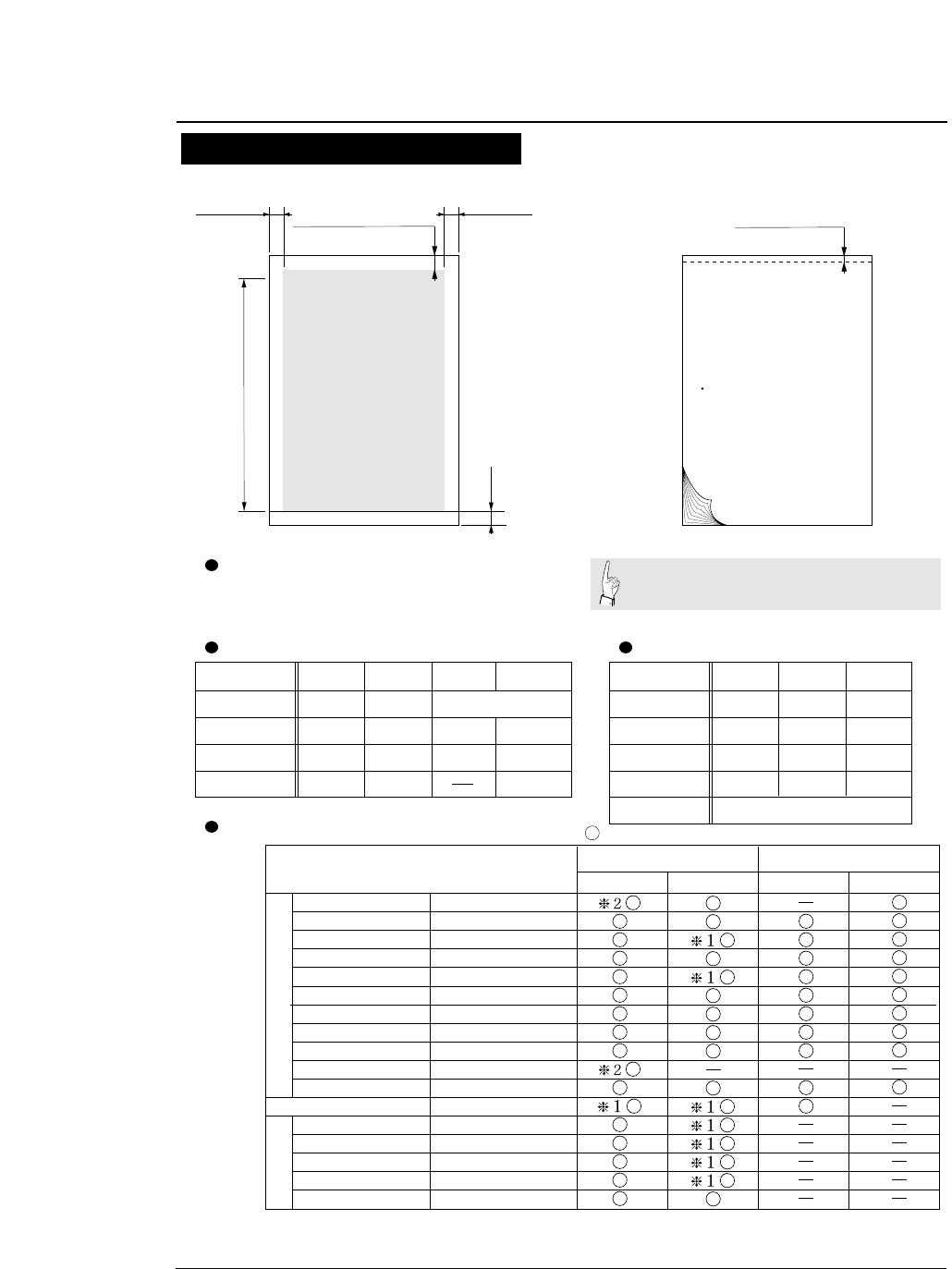
A4, LETTER, LEGAL, A3, etc
(#4 PAGE LENGTH on SETUP MODE)
0/60 inch - 63/60 inches
(#3 TOF ADJUSTMENT on SETUP
MODE)
4mm
Printing area
2 mm or more2 mm or more
Horizontally loaded
size A5 sheets and
postcards cannot be
ejected upward.
Standard-size form Multipart paper
Glued portion
Approx. 0.5 mm
The thickness of the bound
portion is the sum of the
paper thickness and 0.25 mm
or less.
Use wood-free paper. Cut sheet paper can be
loaded manually or by using the CSF.
Paper form
Paper quality
Number of sheets
Thickness (mm)
Paper weight
Single
0.08 ~ 0.12
55 ~ 90kg 34kg x 9P
0.12 ~ 0.59 0.08 ~ 0.8 0.5 or less
Wood-free
paper Wood-free paper
0.08 ~ 0.11
55 ~ 78Kg 34kg x 6P
0.12 ~ 0.39 0.08 ~ 0.22
Manual paper feeding CSF paper feeing
Available standards-size forms
Envelopes and horizontally set post cards
cannot be printed by using the CSF.
Non-carbon, middle carbon
and back carbon multipart
paper can be used.
Multipart
form
19 or less 11
Card Envelope
Carbon or
non-carbon
Paper form
Paper quality
Number of sheets
Thickness (mm)
Paper weight
Paper length
Single
Wood-free
paper
1
Multipart
form
6 or less
Non-carbon
140mm and over
Card
Wood-free
paper
1
39 ~ 78kg 55 ~ 165kg
Paper Size Manual Feeding CSF Feeding
A3
A4
A5
Letter
Half Letter
Legal
Executive
Government Legal
Government Letter
Ledger
F4
Post card
Commercial -6
Commercial -10
Monarch
DL
C5
Portrait Landscape Landscape
(297mm X 420mm)
(210mm X 297mm)
(148mm X 210mm)
(8.5" X 11")
(5.5" X 8.5")
(8.5" X 14")
(7.25" X 10.5")
(8.5" X 13")
(8" X 10.5")
(11" X 17")
(210mm X 330mm)
(100mm X 148mm)
(6 1/2" X 3 5/8")
(9 1/2" X 4 1/8")
(3 7/8" X 7 1/2")
(110mm X 220mm)
(162mm X 229mm)
❈1 Paper length 150mm (5.9inch) or less can not be ejected to the top.
❈2 A3 (portrait) or Ledger (portrait) can not be stacked on the top paper rack.
Regular size formEnvelope
Portrait
—1. Setting up the printer—
●
Paper
Printing area on cut sheet paper Specify the paper size of cut sheet paper using #4 PAGE
LENGTH on the SETUP MODE. For setting, see page 1-19.
1-10 —1. Setting up the printer—
●
Selecting the paper form
Paper form selection 1
15
12:
10:
5:
15 inches
12 inches
10 inches
5 inches
Paper Width
(Fanfold Paper)
2
16.5
A3
A4
A5
LT
HLT
LG
LD
EX
: 2 inches
: 16.5 inches
: A3
: A4
: A5
: LETTER
: HALF LETTER
: LEGAL
: LEDGER
: EXECUTIVE
Page Length (Fanfold Paper)
Paper Size (Cut Sheet Paper)
GLT
GLG
F4
PC
C6
C10
MN
DL
C5
: GOVERNMENT LETTER
: GOVERNMENT LEGAL
: F4 SIZE
: POST CARD
: COMMERCIAL-6
: COMMERCIAL-10
: MONARCH
: DL Envelop
: C5 Envelop
F1.5x 5
.TR REAR1
p:
l: Portrait
Landscape
Orientation
(Cut Sheet Paper)
Page
Length
1
11x 5F
.
TR REAR
IN OUT FORM
PAPER PATH PAPER FORM
4Ap4
PAPER FORM
PAPER FORM
PAPER FORM
PAPER FORM
PAPER FORM
PAPER FORM
PAPER FORM
111 I x 15
IN
1
211 I x 15
NIN
311 I x 15
IN
5Ap4
6Ap4
N
N
Factory default setting
Liquid crystal display
If the EEPROM is
initialized, preset form
sizes are replaced by the
factory default settings.
Sizes of up to six frequently-used forms may be stored in MEMO 1 to MEMO 6 in the internal memory.
Any of the stored sizes may be read out of the memory with the PAPER FORM key whenever necessary.
See page 1-31.
1-11
—1. Setting up the printer—
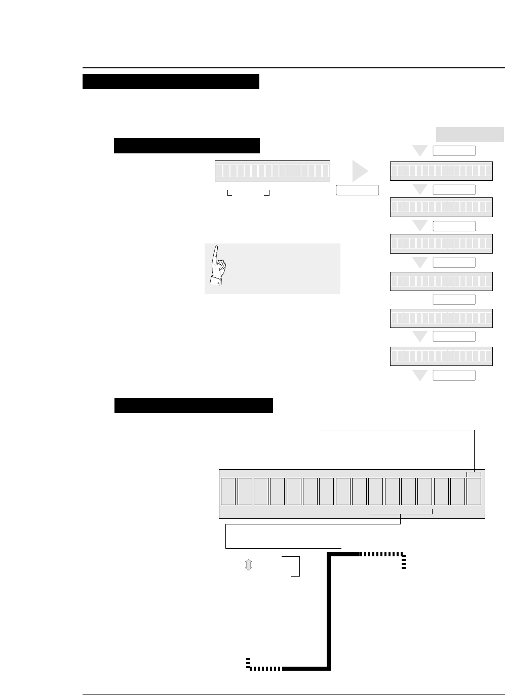
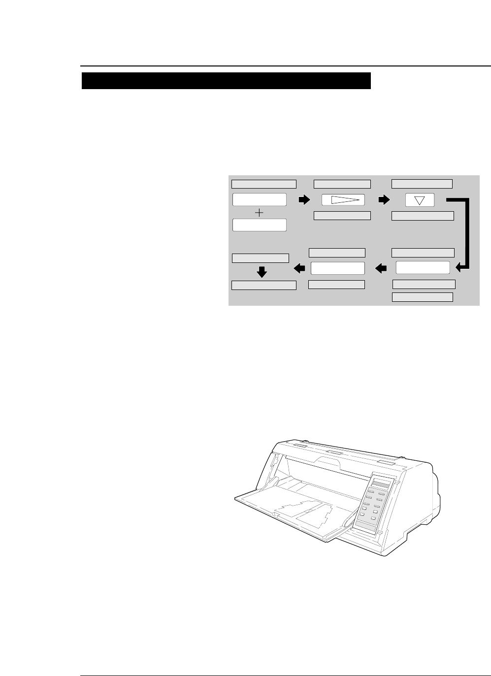
1. Press the PAPER FORM key.
The paper size currently selected is displayed.
2. Continue to press the PAPER FORM key to
select MEMO 3 as shown below.
3. Specify the intended form size as shown
below.
4. The A5 portrait form is set in MEMO 3.
●
Selecting the paper form
Paper form selection 2
The following shows an example of setting form size for reference. The example below
shows how to change the size stored in MEMO 3 ( page length: 11 inches, paper width:
15 inches) to an A5 portrait form.
Specifying form size
11 5xF
.
TR RE
I
IN OUT PAPER FORM
PAPER PATH
IN OUT
PAPER PATH
PAPER FORM PAPER FORM
N1xIA1R11N51
SET UP
F.TR REAR 11 x 15 1. MULTIPART
4. PAGE LENGTH SIZE: A5 p
PAGE:11 INCH
1. MULTIPART
SIZE: A5 p*
ENTER
SIZE: A5 p
EXIT
SAVE?: YES
ENTER
SAVE?: YES
F.TR REAR A5 p
4. PAGE LENGTH
4. PAGE LENGTH
PAPER PATH
ENTER
IN OUT
PAPER PATH
FORM
11x 5F
.
RT
IN OUT
PAPER PATH
FORM
IN OUT
PAPER PATH
FORM
1
MEM 1F.R->R ATERO
MEM 1F.R->T PTO
->T PO
O
1-12
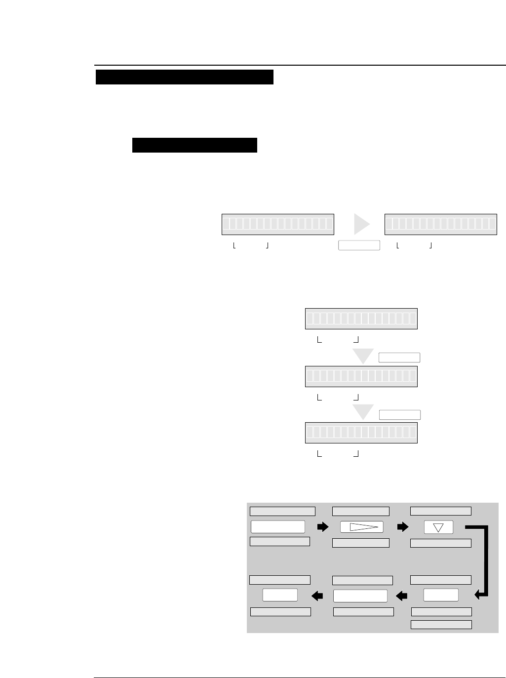
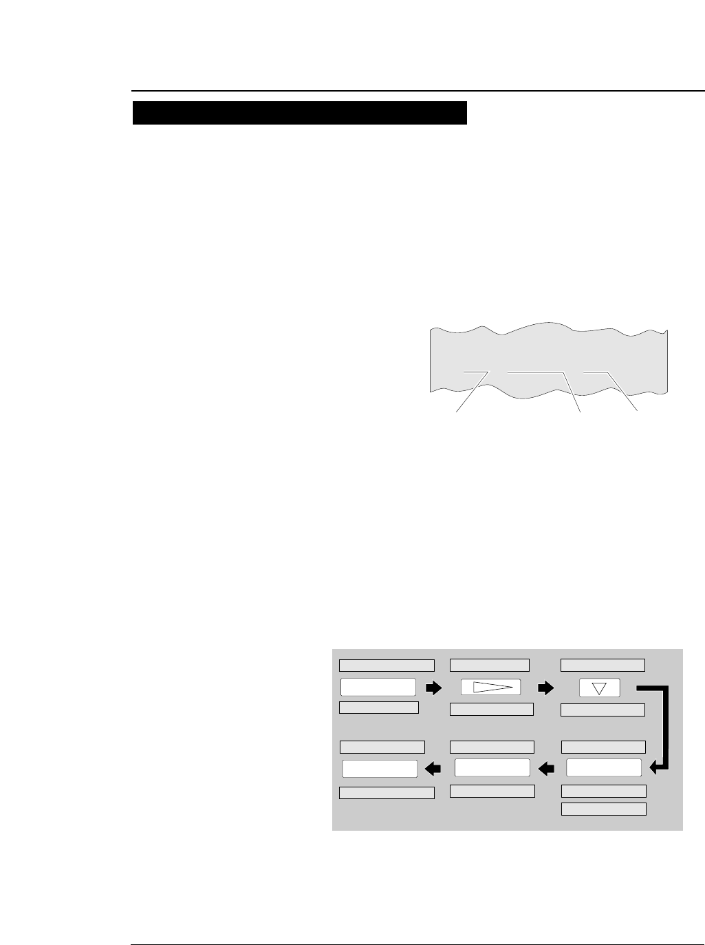
1. Check the rating of the fanfold paper to be
used that is marked on the side of the
package.
2. Press the PAPER PATH key to select the
desired paper path.
—1. Setting up the printer—
●
Loading fanfold paper (Front tractor)
Fanfold paper setting procedures 1
This section describes how to set fanfold paper for front loading and rear ejection
or front loading and top ejection. Before setting fanfold paper, it is necessary to
specify the page length, paper width, etc. on the SETUP MODE.
Rating
10 X 11 - 1P
Page lengthPaper width
Fanfold paper rating marked on side of package (Example)
Multipart paper
(Number of sheets)
Paper loading direction
Paper loading direction
F.TR REAR 11 x 15 F.TR TOP 11 x 15
1
1
3. Specify the page length using #4 PAGE
LENGTH on the SETUP MODE as shown
below.
4. Then specify the paepr width using #5
PAPER WIDTH on the SETUP MODE as
shown below.
1-13
—1. Setting up the printer—
●
Loading fanfold paper (Front tractor)
Fanfold paper setting procedures 2
SET UP
1. MULTIPART
4. PAGE LENGTH
1. MULTIPART
ENTER
4. PAGE LENGTH
F.TR REAR A5 p
PAGE: 11 INCH
SIZE: A5 p*
PAGE: 11 INCH
PAGE: 11 INCH*
4.PAGE LENGTH
ENTER
5.PAPER WIDTH
SAVE?: YES
F.TR REAR 11 x 10
WIDTH: 10 INCH
WIDTH: 15 INCH*
WIDTH: 10 INCH*
ENTER
WIDTH: 10 INCH
EXIT
SAVE?: YES
5.PAPER WIDTH
1-14
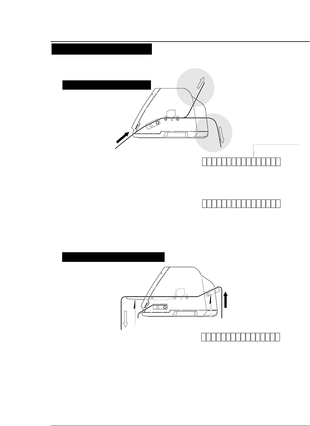
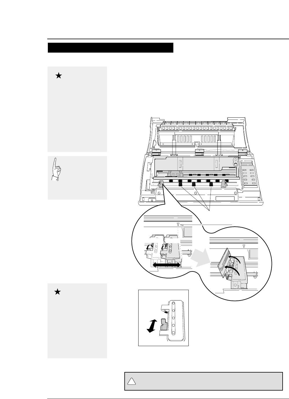
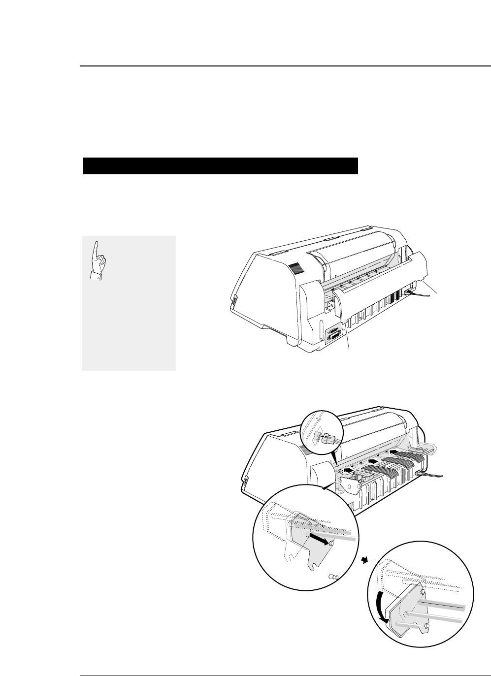
5. Open the front cover.
6. Lift to release the tractor lock lever. Move
the left tractor to the triangle mark. Then
push down on the lever.
—1. Setting up the printer—
●
Loading fanfold paper (Front tractor)
Fanfold paper setting procedures 3
Do not put your finger under the tractor cover.
Triangle mark
Lock lever
Release
Lock
Tractor guide
Release Lock
CAUTION
!
Open the front cover by
pressing both side locks
with both hands. Hold
both sides with both
hands to raise it upward
slowly. When closing
the front cover, hold
both sides with both
hands to pull it down
slowly. Press the front
cover to lock it.
Caution
Push the lock levers of
both tractors to the
LOCK positions firmly.
If the lock levers
protrude from the
tractor covers, paper
will not be fed properly,
resulting in paper
jamming.
Caution
In order to load
less than 5 inch
width fanfold
paper, remove one
or two tractor
guides.
1-15
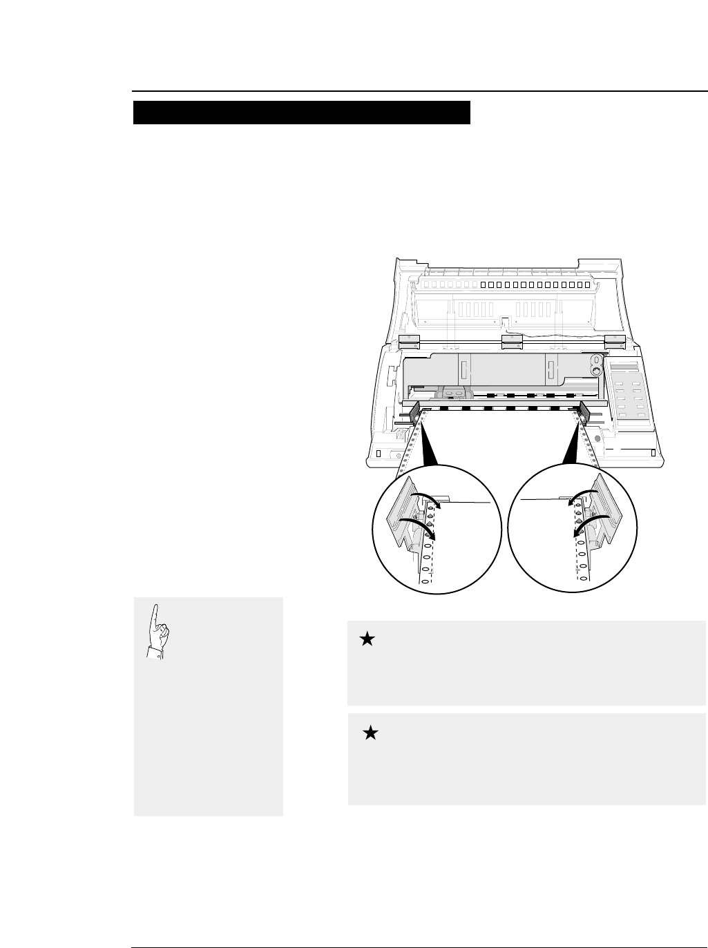
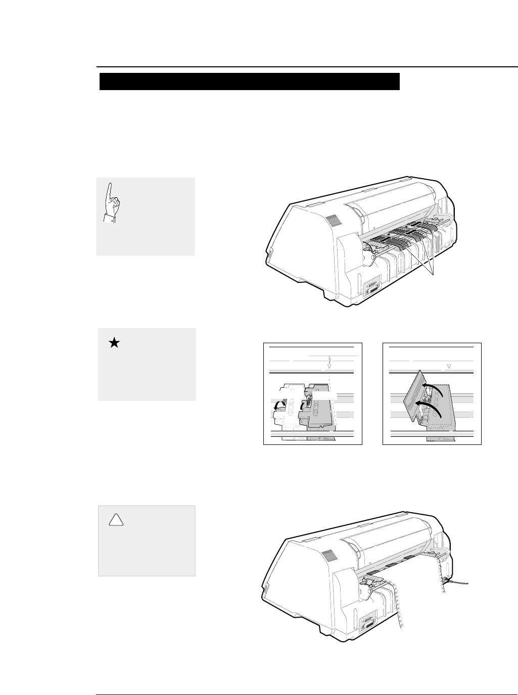
7. Open the tractor covers on both sides. Fit
the sprocket holes on both sides of the
fanfold paper to the tractor pins. Then close
the tractor covers. Push down the lock lever
of the right tractor.
8. Close the front cover.
Hold both sides of the front cover with both
hands and pull down the front cover slowly.
Press the front cover to lock it.
—1. Setting up the printer—
●
Loading fanfold paper (Front tractor)
Fanfold paper setting procedures 4
By default, paper is
fed to the 14/60
inch (approximately
6 mm) position
from the top. This position
may be freely adjusted on
the SETUP MODE
between 0/60 inch (0 mm)
and 63/60 inches
(approximately 26.7 mm)
from the top of paper or the
perforation at a pitch of
1/60 inch.
The TOF position can be set from 0/60 inch (0
mm). However, if this position is set to 0/60 to
9/60 inch, paper may jam, depending on the paper condition. Normally,
it is recommended that the TOF position be adjusted to the 14/60 inch
(approximately 6 mm) position from the top of the paper.
Caution
when setting the paper on the tracter, Take care
not to over tighten or allow too much slack. Over
tightening deforms the guide holes and the paper may become
disconnected from the tracter during printing. Too much slack may
cause the paper to become clogged when it is inserted.
Caution
1-16 —1. Setting up the printer—
●
Loading fanfold paper (Rear tractor)
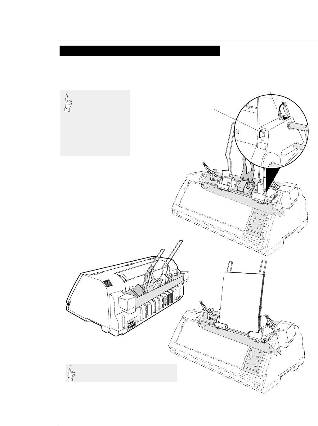
1. Detach the rear printer cover from the
printer.
2. Install the rear tractor, and plug in the
connector.
Dual paper parking is available if the optional rear tractor is used. This funcion
enables two types of fanfold paper of different formats to be set together and
selected with the PAPER PATH key on the printer or by issuing a setup command
from the computer.
1
Leg
Leg
1
Paper setting procedures usig rear tarctor 1
Pull the upper
part of the rear
printer cover to
the front to
detach it from the printer.
When attaching the rear
printer cover, insert
the two legs into the
printer and then press
the rear printer cover
to lock it.
1-17
—1. Setting up the printer—
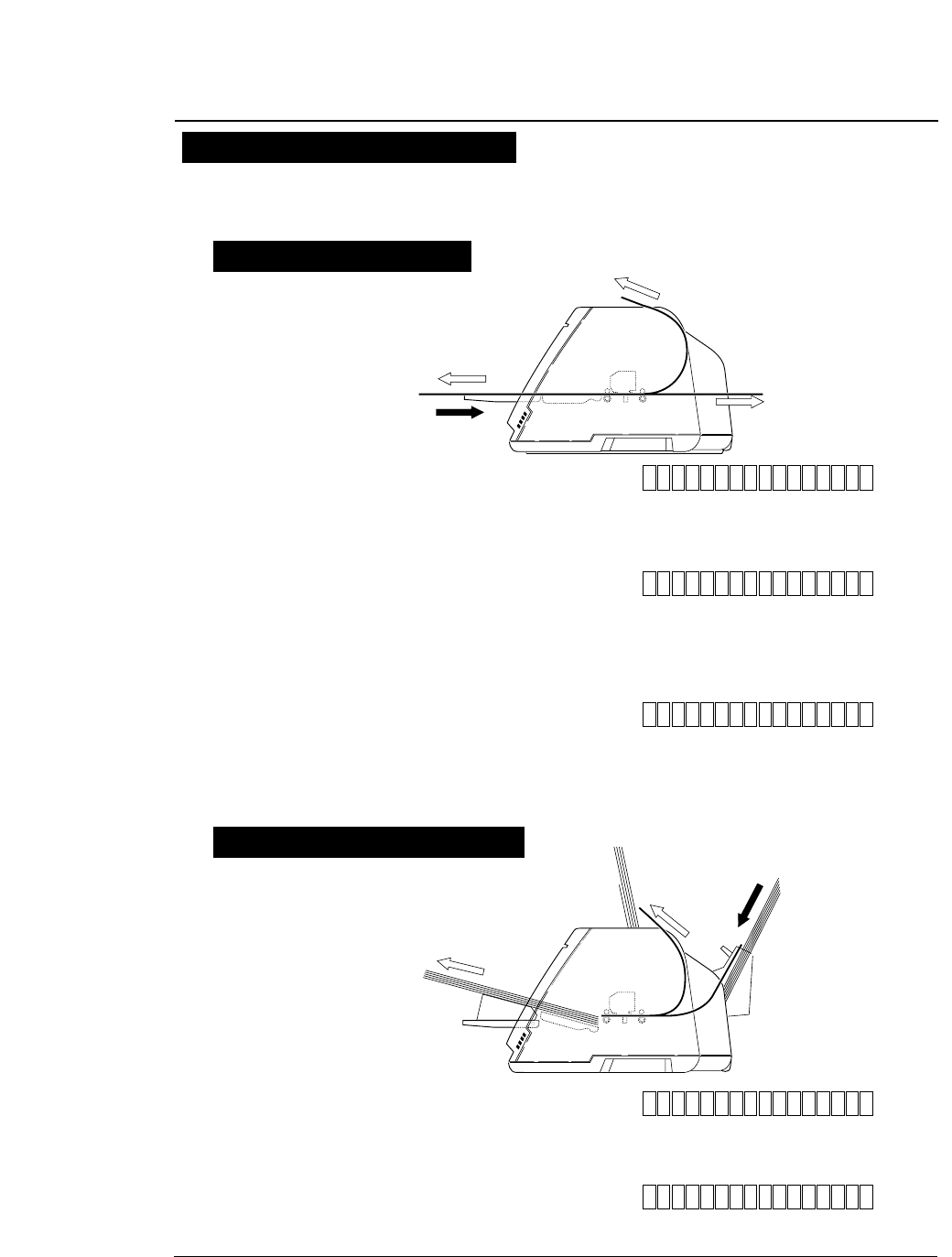
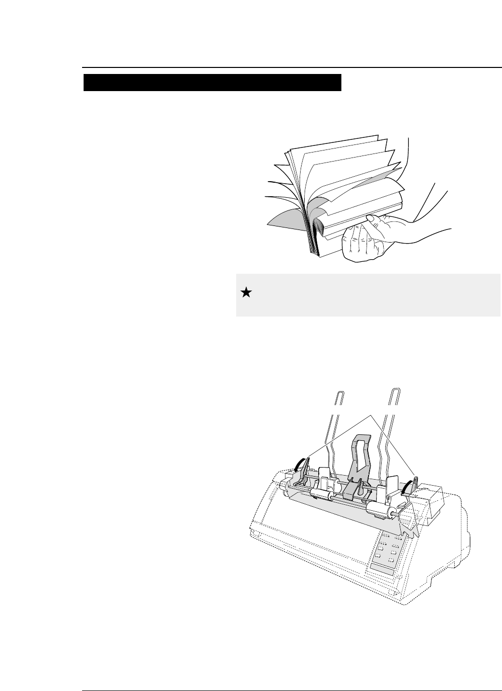
3. Adjust the tractor guides so that they are
located at almost the same interval. Lift and
release the tractor lock levers. Move the left
tractor to the triangle mark, then push down
the lever.
4. Set fanfold paper onto the rear tractor. Push
down the lock lever of the right rear tractor.
●
Loading fanfold paper (Rear tractor)
Triangle mark
1
Tractor guide
Lock
Release
1
Paper setting procedures usig rear tarctor 2
Push the lock levers of
both tractors to the
LOCK positions firmly.
Caution
Do not put your
finger under the
tractor cover.
CAUTION
!
In order to load
less than 8 inch
width fanfold
paper, remove
one or two tractor
guides.
1-18
5. Enter the EXTENDED SETUP MODE. Select
the rear tractor on this menu so that the
printer recognizes that the rear tractor is in
use.
6. Press the PAPER PATH key to select REAR
Tr FRONT.
7. “OPEN PAPER RACK” will be displayed. Open
the paper rack.
—1. Setting up the printer—
●
Loading fanfold paper (Rear tractor)
SET UP
F.TR REAR 11 x 10 20. EMULATION
60. OPTION
NOT INSTALL*
60. OPTION
ENTER
EXIT
F.TR REAR 11 x 10
ALT
60. OPTION
INITIAL
INITIAL OPTION: REAR Tr.*
OPTION: REAR Tr.
OPTION: REAR Tr.
Paper setting procedures usig rear tarctor 3
1. Check the rating of the cut sheet paper to be
used that is marked on the side of the
package.
2. Press the PAPER PAHTH key to select
MANUAL FRONT or MANUAL TOP, or MANUAL
REAR .
3. Specify the form size correctly on the
SETUP MODE (#4 PAGE LENGTH).
1-19
—1. Setting up the printer—
●
Loading cut paper (manual paper feeding)
Select Manual feeding procedures 1
This section describes how to load cut sheet paper, showing an example of using
an A5 portrait form. Before loading a cut sheet, it is necessary to specify the
paper size on the SETUP MODE. Be sure to load cut sheet paper one sheet at a
Rating
A5 (Wood-Free / 70kg)
Wood-free paper
Form size
Cut sheet paper rating marked on side of
package (Example)
Paper weight
1. MULTIPART
4. PAGE LENGTH SIZE: A5 p
SIZE: A4 p*
4. PAGE LENGTH
SIZE: A5 p *
ENTER
SIZE: A5 p
ENTER
SET UP
MAN FRNT A4 p
1. MULTIPART
SAVE? : YES*
EXIT
4. PAGE LENGTHSAVE? : YES
MAN FRNT A5 p
1-20
4. Adjust the edge of the paper guide to
approximately 2 mm left of the triangle mark.
Refer to page 1-21 regarding use of the paper rack guide.
●
Loading cut paper (manual paper feeding)
—1. Setting up the printer—
Select Manual feeding procedures 2
Mark
AAAAAAAAAAAAAAAA
AAAAAAAAAAAAAAAA
AAAAAAAAAAA
AAAAAAAAAAAAAAAA
AAAAAAAAAAAAAAAA
AAAAAAAAAAAAAAAA
AAAAAAAAAAAAAAAA
AAAAAAAAAA
AAAAAAAAAAAAAAAA
AAAAAAAAAAAA
AAAAAAAAAAAAAAAA
AAAAAAAAAAAAAAAA
AAAAAAAAAAAAAAAA
1
aaaaaaaaaaaaaaaaa
aaaaaaaaaaaaaaaaa
aaaaaaaaaaaaaaaaa
aaaaaaaaaaaaaaaaa
aaaaaaaaaaaaaaaaa
aaaaaaaaaaaaaaaaa
aaaaaaaaaaaaaaaaa
LOAD
EJECTION
EJEC-
TION
MAN F
MAN
REA TOP
1
EJECTION
R
RN
T
MAN
The triangle mark shows the printing start
position at the left of the printer.
1-21
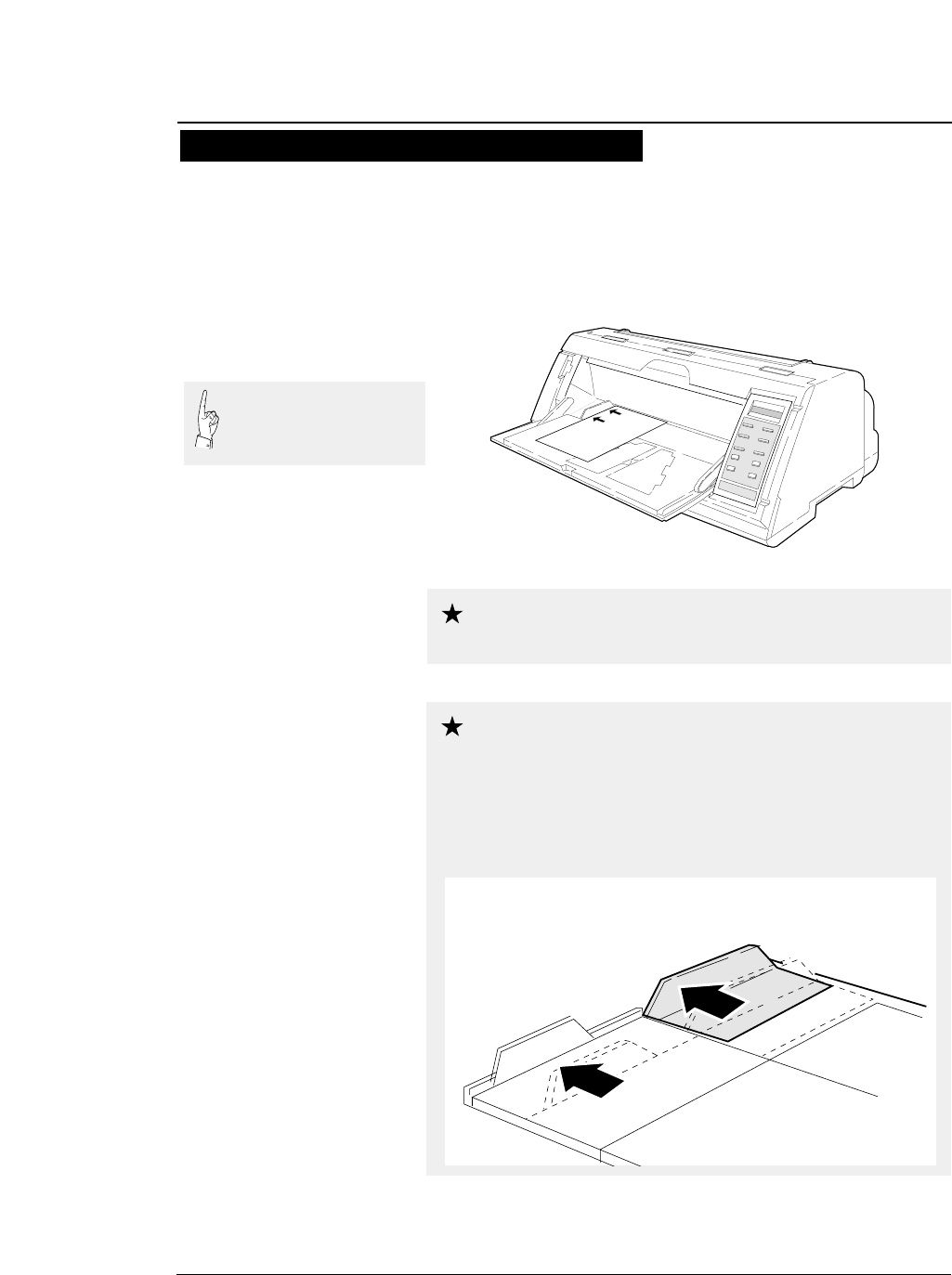
5. Insert a sheet of paper straight along the
paper guide.
If paper is inserted at a skewed angle, the skew sensor detects
and the paper is ejected.
—1. Setting up the printer—
●
Loading cut paper (manual paper feeding)
Insert sheets of paper one at a time along the paper
guide. Only one sheet at a time can be set on the
paper rack.
Select Manual feeding procedures 3
To alternate manual printing and printing with the
optional rear tractor or CSF, be sure to move the
paper guide to the left end after completion of
manual printing. Further, return the paper guide of the paper rack
to the left end. If printing is performed using the rear tractor or
CSF with the paper guide left in the manual feeding position,
paper loaded form the back will hit the paper guide, resulting in
paper jamming.
Move the Paper Guide and the Paper Support Guide to the left end.
Caution
Caution
When using wide paper, insert
the paper using the paper
support guide attached to the
left end of the paper rack.
1-22
1. Press the EJECT/LOAD key to move back
the fanfold paper.
2. Enter the EXTENDED SETUP MODE
according to the proceures shown below
and select #60 OPTION on the menu. Select
CSF (cut sheet feeder).
3. Detach the rear printer cover from the
printer.
—1. Setting up the printer—
●
Printing using the cut sheet feeder (Option)
Printing procedures using CSF 1
An optional cut sheet feeder is available for this printer. The cut sheet feeder is
useful for continuous printing on cut sheets.
The paper holder of the cut sheet feeder accommodates a maximum of 150 sheets
(of 55 kg paper). Normal paper and multipart paper can be used.
SET UP
F.TR REAR 11 x 10 20. EMULATION
60. OPTION OPTION: CSF
NOT INSTALL*
60. OPTION
OPTION: CSF*
ENTER
EXIT
F.TR REAR 11 x 10
ALT
60. OPTION
INITIAL
INITIAL
OPTION: CSF
1
Leg
Leg
Pull the upper
part of the rear
printer cover to
the front to
detach it from the printer.
When attaching the rear
printer cover, insert the
two legs into the printer
and then press the rear
printer cover to lock it.
1-23
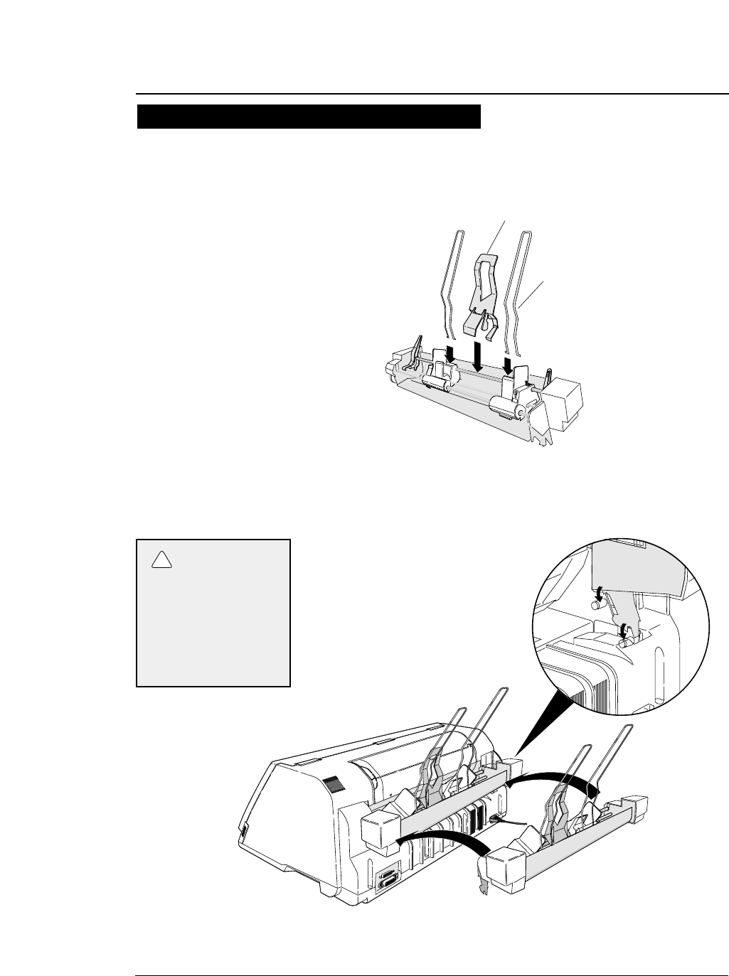
4. Attach the hoppers and center support to
the cut sheet feeder.
5. Attach the cut sheet feeder to the back of
the printer.
—1. Setting up the printer—
●
Printing using the cut sheet feeder (Option)
Printing procedures using CSF 2
1
CSF
1
Hopper
Center support
Use two hands and hold
firmly at each end when
lifting the cut sheet
feeder. Personal injury
can occur if the CSF unit
is dropped.
CAUTION
!
1-24
6. Shuffle the paper as show below.
7. Turn the CSF release levers to the front to
release the paper bins.
—1. Setting up the printer—
●
Printing using the cut sheet feeder (Option)
Printing procedures using CSF 3
Be sure to shuffle sheets sufficiently before setting
them. Otherwise, several sheets of paper may be fed
at the same time resulting in a paper jam.
CSF release lever
Caution
1-25
8. Turn the paper guide lock levers to the
RELEASE positions to adjust the paper
width.
9. Turn the paper guide lock levers to the
LOCK positions.
—1. Setting up the printer—
●
Printing using the cut sheet feeder (Option)
1
Mark
Adjust the edge of the paper guide to
appriximately 2mm left (outside) of the
triangle mark.
CARD
Paper guide lock lever
Postcard changeover lever
When printing on postcards,
turn this lever down.
Release Lock
Printing procedures using CSF 4
The triangle mark shows the printing start
position at the left of the paper.
Adjust the paper guide
to remove the gap
between the paper and
the paper guide, ensuring
that the paper does not press
too tightly against the paper
guide to avoide faulty
feeding.
1-26 —1. Setting up the printer—
●
Printing using the cut sheet feeder (Option)
10. Move the CSF release levers to the back to
fix the paper bins.
11. Press the PAPER PATH key to select CSF
FRONT or CSF TOP.
12. Press the ENTER key to select the displayed
paper path.
CSF TOP A4 p CSF FRNT A4 p
Printing procedures using CSF 5

1-27
—1. Setting up the printer—
1. Turn on the printer power while keeping the
LINE FEED key, or LINE FEED and ONLINE
keys depressed.
After initialization, the printer enters the self-test mode and starts the
self-test.
During printing, the ONLINE lamp blinks at an interval of 0.5 second.
The following message is displayed on the LCD.
The draft or LQ self-test prints the ASCII character in a rolling pattern.
2. To pause the self-test, press the ONLINE
key.
To terminate the self-test, keep the ALT and
RESET keys depressed for two seconds or
more, or turn the power switch to off.
●
Running self-test
It is recommended that a self-test of the printer be performed before connecting
the printer to the computer. The printer can execute the self-test by itself to check
on printing quality, printing pressure, and any printer troubles.
Draft self-test printing: Turn on power while pressing the
LINE FEED key.
LQ self-test printing: Turn on power while pressing the LINE
FEED and ONLINE keys.
Draft self-test printing “SELF TEST DRAFT”
LQ self-test printing “SELF TEST LQ”
1-28 —1. Setting up the printer—
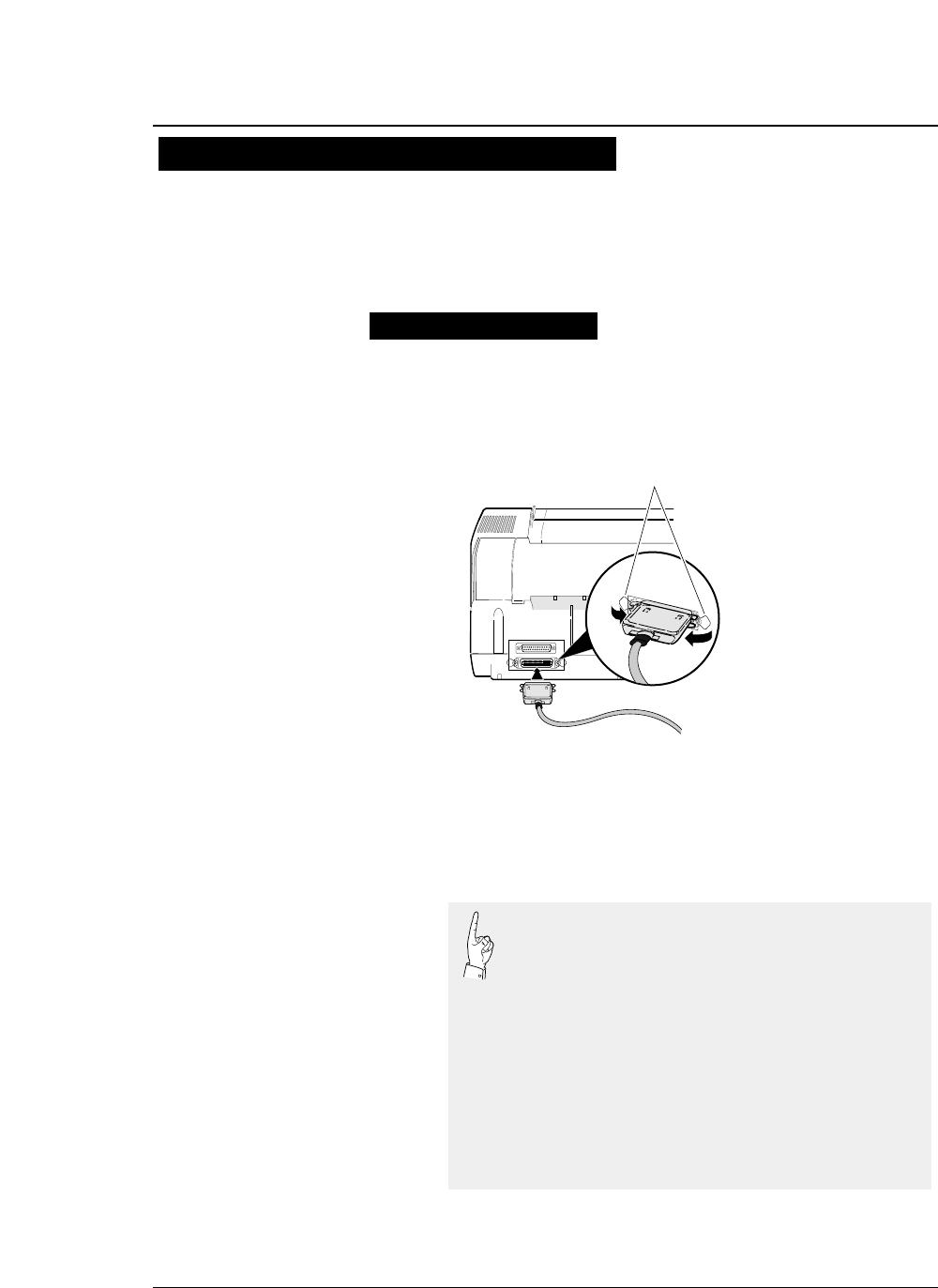
1. Make sure that the power switch is turned to
off. Connect the signal cable to the printer
and computer.
2. Specify the following parallel interface
parameters on the EXTENDED SETUP
MODE.
●
Connecting the printer to the computer
13
25
1
14
Close the latches to secure
the connector.
Latches
Parallel Interface
The printer has a Centronics parallel interface and an RS-232S serial interface
as standard features.
Select the appropriate interface according to the computer and application
software to be used.
Connecting the priter to the computer
The printer has been set to the normal parallel
interface setting before shipment. If the default
setting does not provide proper communication,
recheck the interface setting shown below.
EXTENDED SETUP MODE Default setting page
#70. INTERFACE Parallel 3-46
#71. SELECT IN ENABLE 0 3-47
#81. BUFFER SIZE 512 KB 3-52
#82. BUSY/ACK TIMING TYPE 2 3-53
#83. DATA LATCH TIMING TYPE F. 3-53
#84. ERROR STATUS YES 3-54
1-29
—1. Setting up the printer—
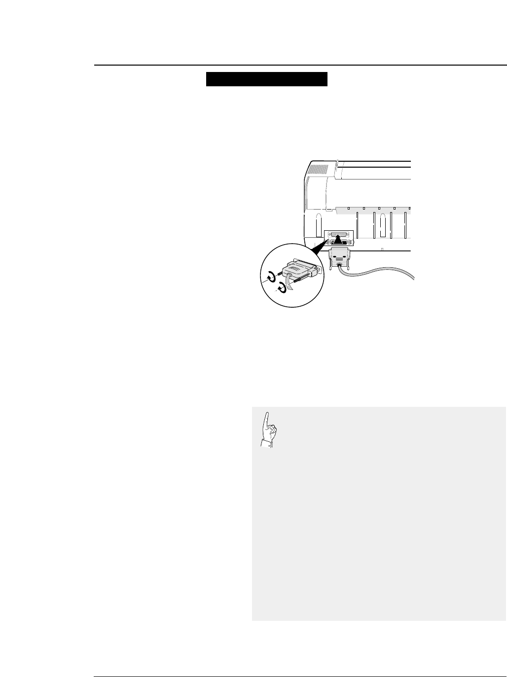
1. Make sure that the power switch is turned to
off. Connect the signal cable to the printer
and computer.
2. Specify the following serial interface
parameters on the EXTENDED SETUP
MODE.
●
Connecting the printer to the computer
Serial Interface
13
25
1
14
Tighten the screws on both
sides of the connector.
Specify the following serial interface parameters on
the EXTENDED SETUP MODE.
EXTENDED SETUP MODE Default setting Page
#70. INTERFACE Parallel 3-46
#
71. SELECT IN ENABLE 0
3-47
#
72. PARITY BIT Non
3-47
#
73. DATA LENGTH 8 bits
3-48
#
74. STOP BIT 1 bit
3-48
#
75. PROTOCOL DTR
3-49
#
76. BAUD RATE 9600 bps
3-49
#
77. SERIAL ERROR Print
3-50
#
78. CTS ENABLE No
3-50
#
79. CD ENABLE No
3-51
#
80. DSR ENABLE No
3-51
#81. BUFFER SIZE 512 KB 3-52

1-30 —1. Setting up the printer—
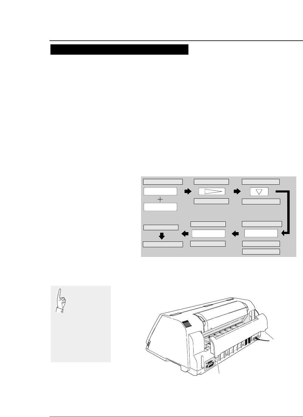
1. Turn on the printer power while keeping the
FORM FEED key or FORM FEED and ONLINE
keys depressed.
While printing the hexadecimal dump list, the following message is
displayed.
2. Output data from the computer to the
printer.
The printer will begin to print the hexadecimal dump list.
3. To stop the dump list printing, depress the
ALT and RESET keys for approximately two
seconds or turn the power switch to off.
●
Input data hexadecimal dump
The printer can print an input data hexadecimal dump list, which contains all
input data in hexadecimal codes and corresponding ASCII characters. It is
possible to use this dump list to check whether data is being transferred in the
proper format by the computer to the printer when printing is not performed
properly.
Outputting the hexadecimal dump list
Draft printing: Turn on power while pressing the FORM FEED key.
LQ printing: Turn on power while pressing the FORM FEED and
ONLINE keys.
HEX DUMP LQHEX DUMP DRAFT
1-31
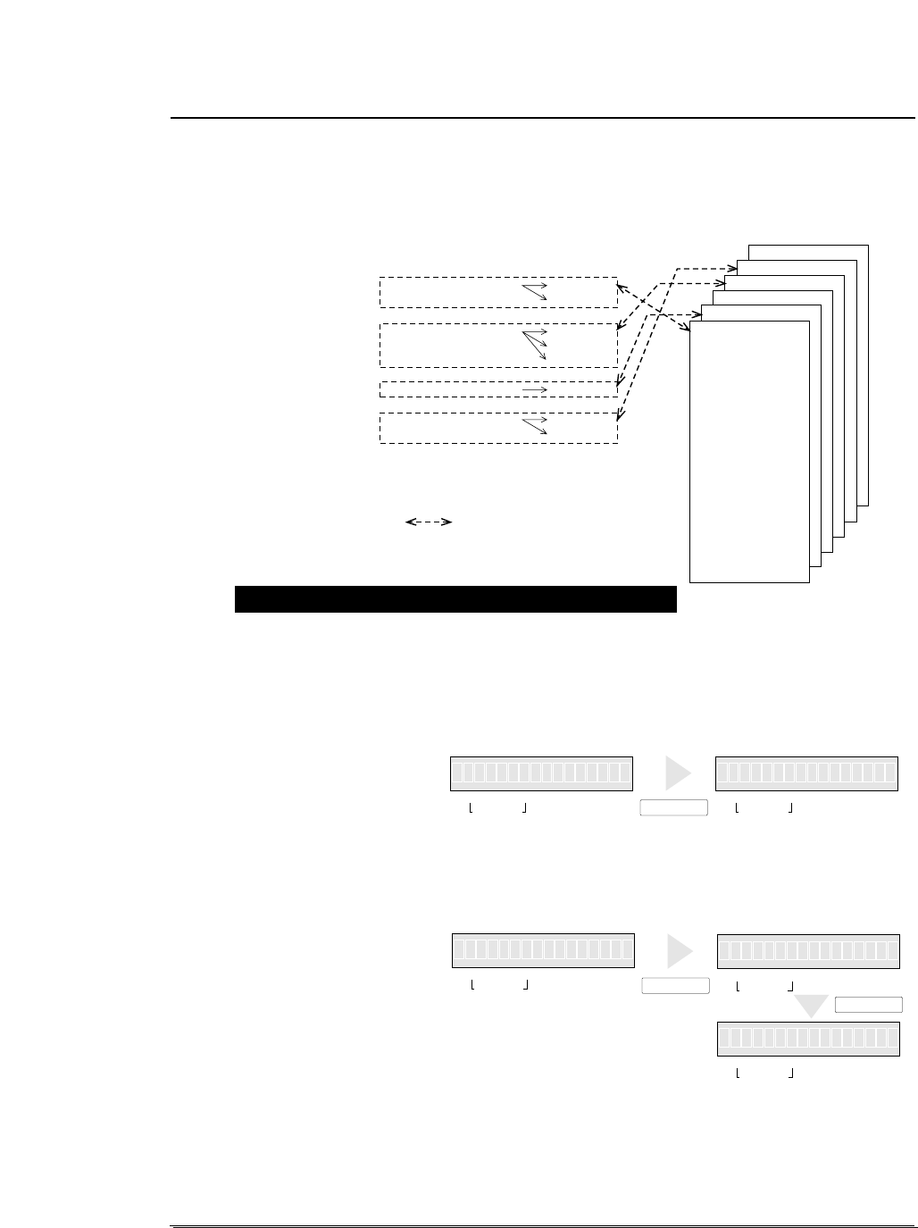
●
Link between paper path (PATH)
and paper form (MEMO)
1. Press the PAPER PATH key to select the
PATH you want to use. Press the ENTER
key.
2. Press the PAPER FORM key to select the
MEMO you want to use. Press the ENTER
key.
3. PATH has been linked to MEMO.
Now, switching to the PATH automatically selects the MEMO linked
to it.
Changes of #1 to #17 on the SETUP MODE are reflected only in the
MEMO linked to the currently selected PATH.
—1. Setting up the printer—
When PATH is changed, MEMO used in a newly set PATH will be changed
automatically.
There are six types of MEMO: MEMO1 through MEMO6. Each MEMO stores
the settings of #1 to #18 on the SETUP MODE.
FRONT TRACTOR REAR
TOP
FRONT
TOP
REAR
FRONT
FRONT
TOP
MANUAL
REAR TRACTOR
CSF
MEMO 6
MEMO 5
MEMO 4
MEMO 3
MEMO 2
MEMO 1
1. MULTIPART
2. HEAD ADJUST
3. TOP ADJUST
4. PAGE LENGTH
5. PAPER WIDTH
6. TOP MARGIN
7. BOTTOM MARGIN
8. LEFT MARGIN
9. RIGHT MARGIN
10. QUALITY
11. FONT SELECT
12. CHARACTER PITCH
13. LF PITCH
14. ZOOM IN/OUT
15. PAPER FASTENER
16. PERFORATION
17. FANFOLD FEED
18. PAPER QUALITY
PAPER PATH
[ IN ] [ OUT ]
Link between PATH and
MEMO by default
Switching links between PATH and MEMO
11 5xF.TR TO R
IN OUT FORM
PAPER PATH
IN OUT
PAPER PATH
PAPER PATH FORM
15xTRE 1FAP R.1 1
111x15
FORM
x5F. E 11TR R AR
IN OUT FORM
PAPER PATH
IN OUT
PAPER PATH
IN OUT
PAPER PATH
ENTER
PAPER FORM
IN 311x15IN
NIIN
FORM
1
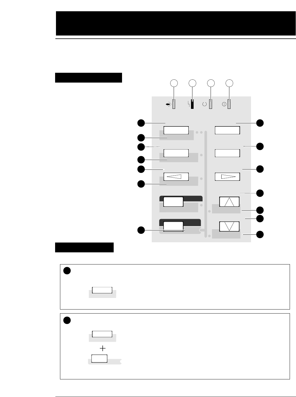
DATA ERROR ONLINE POWER
TEAR OFF ONLINE
PAPER PATH
FORM FEED
LINE FEED
REVERSE LF
TOF SET
QUALITY
EJECT/LOAD
PAPER FORM
RESET
SET UP
MICRO LF
MICRO RLF
EXIT
EXTENDED
ENTER
ALT
1234
1
1TEAR OFF Press the TEAR OFF key, and the printer automatically feeds the
perforation of the paper to the paper cutter position (for fanfold paper
only).
If the perforation is not adjusted to the cutter position, correct the
position with the MICRO LF or MICRO RLF key. The corrected
position is saved in memory, and the perforation is fed automatically to
the paper cutter position next time.
(ALT + TEAR OFF keys)
Press the TEAR OFF key for two seconds or more while you press the
ALT key. When an "INITIAL" is displayed on the LCD, release the
keys. The printer will be reset immediately.
Even during printing, printing can be stopped immediately by resetting
the printer. When the printer is reset, it enters the busy state, the buffer
is cleared, and the printer restarts in the condition that was set on the
SETUP MODE or EXTENDED SETUP MODE (saved in the
EEPROM).
TEAR OFF
RESET
RESET
TEAR OFF
RESET
ALT
2
3
4
5
6
7
8
9
10
11
12
13
14
2
2.
Control panel operations
2-1
—2. Control panel operations —
Function Keys 1
The liquid crystal display (LCD) on the control panel displays the processing
conditions of the printer and the settings of the functions. The keys on the control
panel provide various functions.
Control Panel
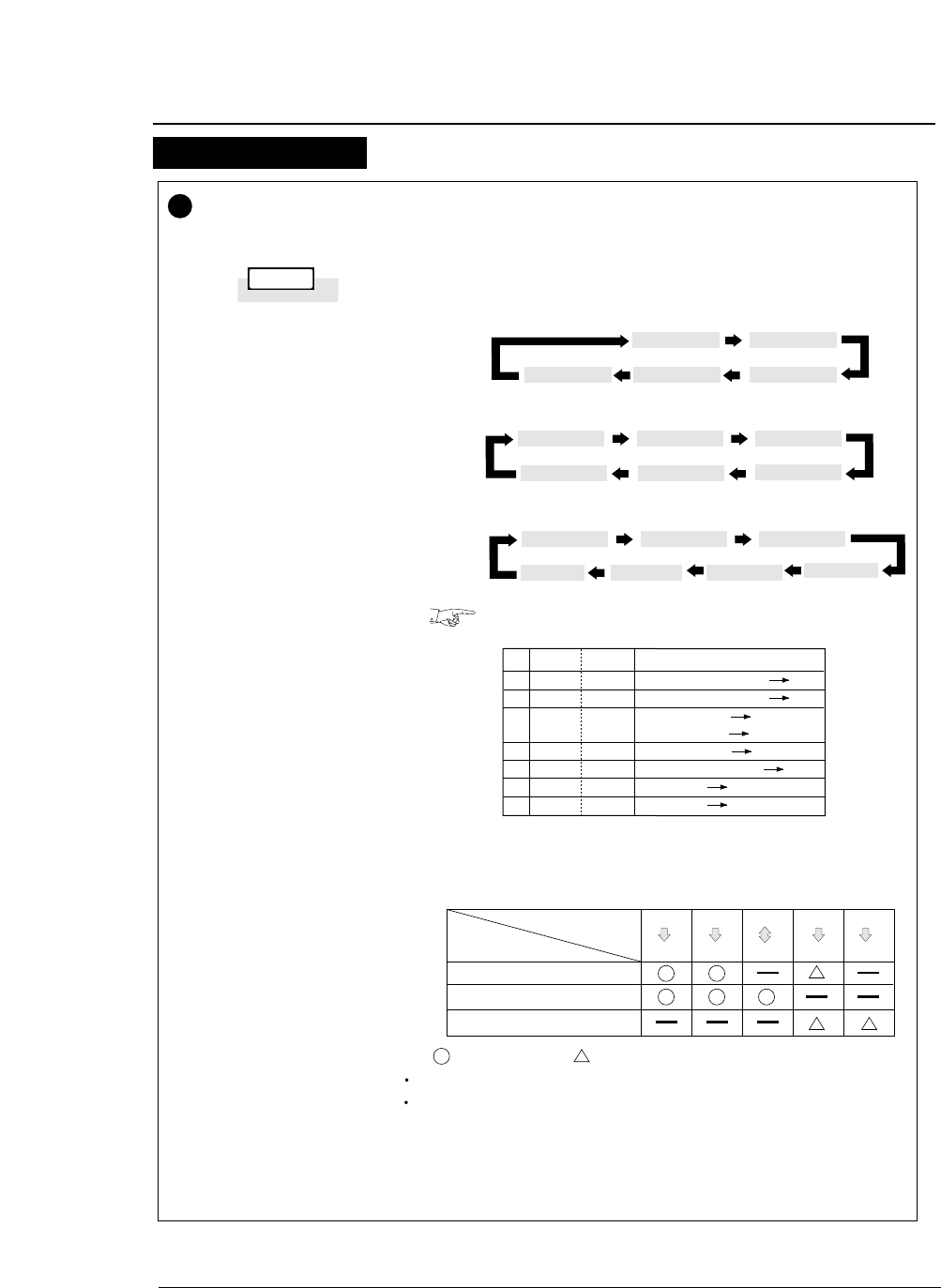
2-2 —2. Control panel operations—
PAPER PATH Press the PAPER PATH key to change the paper path.
When the PAPER PATH key is pressed, the currently selected
paper path is displayed. Every press of the PAPER PATH key
alternates the LCD display as shown below.
Standard Option (Rear tractor or CSF)
To select the displayed paper path, press the ENTER key.
If the paper path is changed when fanfold paper or cut sheet
paper is loaded, the fanfold paper is fed back to the parking
position or the cut sheet paper is ejected.
1.
2.
3.
4.
5.
6.
7.
8.
F.TR
F.TR
MAN
MAN
MAN
R.TR
CSF
CSF
REAR
TOP
FRNT
TOP
REAR
FRNT
FRNT
TOP
Fanfold paper: Front Rear
Fanfold paper: Front Top
Manual: Front Front
Manual:Front Top
Manual: Front Rear
Fanfold paper: Rear Front
CSF :Rear Front
CSF :Rear Top
EJECT
LOAD PAPER PATH
Fanfold paper, Push tractor
Cut sheet paper, Manual
Cut sheet paper, CSF
PAPER PATH Front
Top
Front
Rear
Front
Front
Rear
Front
Rear
Top
F.TR REAR F.TR TOP
MAN FRNT
F.TR REAR F.TR TOP MAN FRNT
MAN REAR MAN TOP
F.TR REAR F.TR TOP MAN FRNT
CSF TOP MAN TOP
CSF FRNT
♦When no options are installed
♦When the optional CSF is installed
The CSF and rear tractor cannot be used together.
PAPER PATH
TOF SET
3
MAN REAR
♦When the option rear tractors are installed
PAPER & FEED
MAN TOP
R.TR FRNT
MAN REAR
Function Keys 2
●
Control panel operations
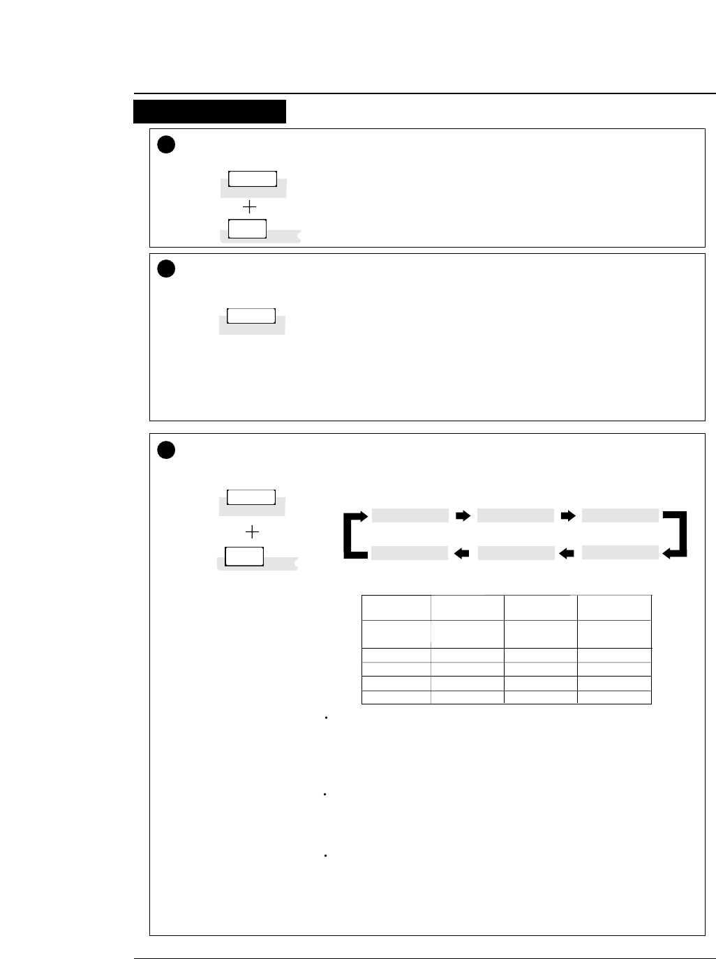
●
Control panel operations
2-3
—2. Control panel operations —
4TOF SET (ALT + PAPER PATH keys)
• The TOF SET key is valid only when paper is loaded. When the TOF SET
key is pressed, the current printing position is regarded as the TOF position.
• The TOF ADJUST option on the SETUP MODE specifies the position when
loading paper. The TOF SET key becomes valid after paper has been
loaded.
• If the TOF position is changed when cut sheet paper is used, the changed
TOF position is valid only for the paper already loaded.
• If the EJECT/LOAD key is pressed when fanfold paper is loaded, the paper
is fed back to the parking position. When it is pressed when cut sheet paper
is loaded, the paper is ejected.
• When the EJECT/LOAD key is pressed under the condition where fanfold
paper is at the parking position, the paper is loaded to the TOF position.
• When the EJECT/LOAD key is pressed with no paper in the manual mode,
the key is ignored. When it is pressed with paper loaded in the manual
mode, the printer ejects the paper.
• When the EJECT/LOAD key is pressed with no paper in the CSF mode, the
printer loads paper. When it is pressed with paper loaded in the CSF mode,
the printer ejects the paper.
PAPER PATH
TOF SET
EJECT/LOAD
EJECT/LOAD
QUALITY
5
ALT
QUALITY
EJECT/LOAD
QUALITY
ALT
6
LCD
LQ
NLQ
HQDR
DRAFT
S.D.
S.S.D.
ESC x 1
LQ is selected.
LQ
NLQ
LQ
LQ
S.D.
S.S.D.
ESC x 0
Draft is selected.
Draft
Draft
HQDR
Draft
S.D.
S.S.D.
Normal
High speed 1
High speed 2
High speed 2
High speed 2
High speed 2
Press the QUALITY key to display the currently selected printing quality on
the LCD. Continue to depress the key to display the printing qualities in the
following order.
To select the displayed printing quality, press the ENTER key.
LQ NLQ HQDR
DRAFT
S.D.S.S.D.
The #10 QUALITY menu selected from the SETUP MODE provides
the same functions as the QUALITY key. Priority is given to the last
setting. Thus, if the printing speed is changed on the menu after setting
it with the QUALITY key, the changed printing speed on the menu is
selected.
If "YES" is selected with the QUALITY LOCK option on the
EXTENDED SETUP MODE, or "S.D." or "S.S.D." is selected with the
QUALITY option on the SETUP MODE, all software commands for
changing the printing quality are ignored.
If "S.D." is selected, the draft characters are printed at 12 cpi at a speed
1.2 times as high as the normal speed. If "S.S.D." is selected, the
characters are printed at 15 cpi at a speed 1.5 times as high as the
normal speed. When "LQ" is not selected, 180/360/120/240-DPI
graphics are printed at high speed with lower bit density.
(ALT + EJECT/LOAD keys)
(When in the EPSON mode)
Graphic speed
Function Keys 3
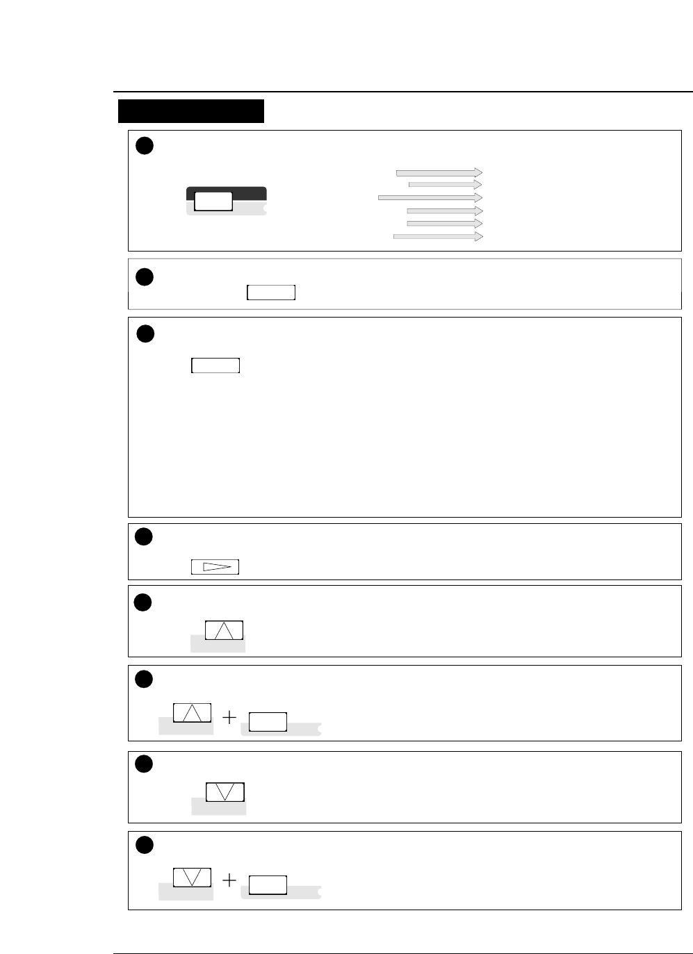
2-4 —2. Control panel operations —
7ALT The following functions are executed by pressing the corresponding
key while you press the ALT key.
Press the ONLINE key to change the printing enabled (online) state and
printing disabled (offline) state.
ONLINE ONLINE
8
LINE FEED
REVERSE LF
SET UP
EJECT/LOAD
PAPER PATH
TEAR OFF
MICRO LF
MICRO RLF
EXTENDED SET UP
QUALITY
TOF SET
RESET
ENTER
ALT
PAPER FORM
PAPER FORM
9Press the PAPER FORM key to change the format memory for the
currently selected paper path. Each press of the PAPER FORM key
changes the format memory as shown below.
Format memory 1
Format memory 2
Format memory 3
Format memory 4
Format memory 5
Format memory 6
The number of the format memory and the paper size stored in the
format memory are displayed on the LCD.
To select the displayed paper form, press the ENTER key.
13 Press the REVERSE LF key to feed the line in the reverse direction at a
pitch of 1/6 inch.
• Keep the key depressed for continuous reverse line feeding.
REVERSE LF
10 Press the FORM FEED key to feed the page at the currently set page
length.
FORM FEED
(ALT + REVERSE LF keys)
Press the MICRO RLF key to feed the line in the reverse direction at a
pitch of 1/360 inch. (Use this key to adjust the paper position.)
14 MICRO RLF
11 Press the LINE FEED key to feed the line in the forward direction at a
pitch of 1/6 inch.
LINE FEED
(ALT + LINE FEED keys)
Press the MICRO LF key to feed the line in the forward direction at a
pitch of 1/360 inch.
12 MICRO LF
FORM FEED
LINE FEED
MICRO LF
LINE FEED
MICRO LF ALT
REVERSE LF
MICRO RLF
REVERSE LF
MICRO RLF
ALT
●
Control panel operations
Function Keys 4
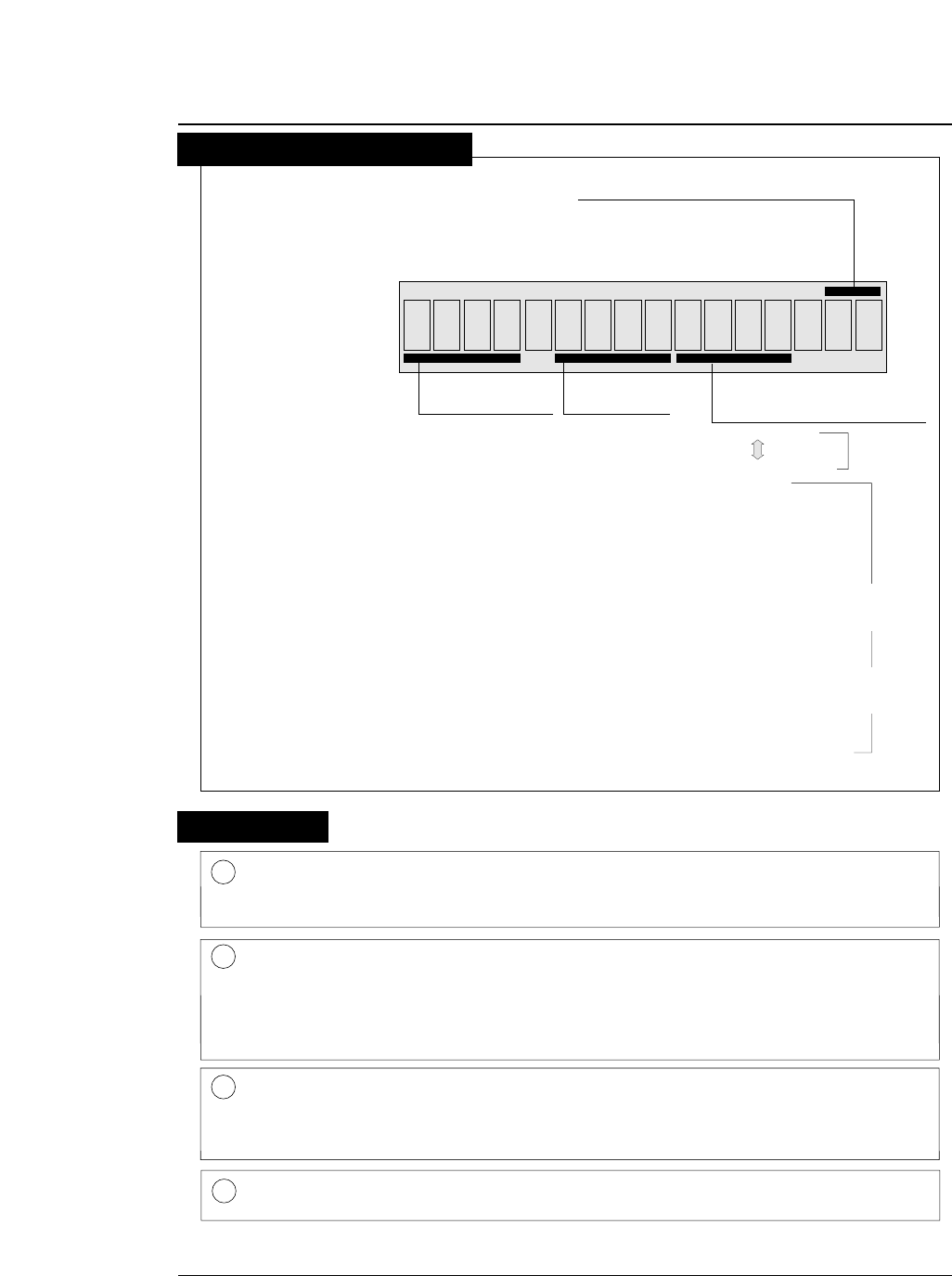
2-5
—2. Control panel operations —
1.5x
F. TR REAR
F. TR
R. TR
MAN
CSF
: Front Tractor
: Rear Tractor
: Manual
: Cut Sheet Feeder
REAR
TOP
FRNT
: Rear
: Top
: Front
1 inch = 25.4 mm
Paper In Paper Out
15 :
12 :
10 :
5 :
15 inches
12 inches
10 inches
5 inches
Paper Width
(Fanfold Paper)
2
16.5
A3
A4
A5
LT
HLT
LG
EX
GLT
GLG
LD
F4
PC
C6
C10
MN
DL
C5
Page Length (Fanfold Paper)
Paper Size (Cut sheet paper)
1DATA (Green) Blinks while data is transferred. Lights while data is processed except
during communication or when the input buffer contains data. Goes
out in other state.
2ERROR (Amber) ON: No paper is detected or other operational error occurs.
OFF: No error is detected.
Blinking: A functional error has occurred (such as home sense error,
internal RAM error, paper path switching error, head adjustment
error, park error and skew error).
3ONLINE (Green) ON: Printing is enabled.
OFF: Printing is disabled.
Blinking: The cover is open, or the printer is in the head temperature
protect mode.
4POWER (Green) Lights when the printer power is on. Goes out when the printer power
is turned off.
: 2 inches
: 16.5 inches
: A3
: A4
: A5
: LETTER
: HALF LETTER
: LEGAL
: EXECUTIVE
: GOVERNMENT LETTER
: GOVERNMENT LEGAL
: LEDGER
: F4 SIZE
: POST CARD
: COMMERCIAL-6
: COMMERCIAL-10
: MONARCH
: DL Envelope
: C5 Envelope
Page
Length
Paper
Size
1
p :
l :
Orientation
(Cut sheet Paper)
Portrait
Landscape
51
Lamps
●
Control panel operations
Liquid Crystal Display

3.Setup options
3-1
— 3. Setup options —
The setup modes consist of the SETUP MODE and EXTENDED SETUP
MODE.
The SETUP MODE is used to set the parameters that can be saved in
the format memories (memo 1 to memo 6). The EXTENDED SETUP
MODE is used to set other parameters.
●
The following parameters can be set in the SETUP MODE.
:
#1.
MULTIPART (Printing pressure)
#2.
HEAD ADJUSTMENT (Paper thickness adjustment)
#3.
TOF ADJUSTMENT (Top-of-form setting)
#4.
PAGE LENGTH (Page length of fanfold paper or paper size of cut sheet)
#5.
PAPER WIDTH (Fanfold paper)
#6 ~ 9
.
Printing margin setting
#10.
QUALITY (Printing quality)
#11.
FONT SELECT (Font selection)
#12.
CHARACTER PITCH (Character pitch)
#13.
LF PITCH (Line feed pitch)
#14.
ZOOM IN/OUT (Zooming magnification)
#15.
PAPER FASTENER (Paper fastener mode setting)
#16.
PERFORATION (Perforation head-up mode setting)
#17.
FANFOLD FEED (Fanfold feed setting)
#18.
PAPER QUALITY
#19.
SELECT SAVE MEMORY (Memo 1 to memo 6)
#20.
SELECT LOAD MEMORY (Memo 1 to memo 6)
●
The following parameters can be set in the EXTENDED
SETUP MODE.
:
Menus #20 to #95 are used mainly to set the following
parameters:
Emulation, font, paper handling, interface, bar codes,
enlarged characters.
●
Entering the SETUP MODE
:
Press the SET UP key to enter the SETUP MODE. To
quit the SETUP MODE, press the EXIT key.
●
Entering the EXTENDED SETUP MODE
:
Press the SET UP key and ALT key simultaneously to
enter the EXTENDED SETUP MODE. To quit the
EXTENDED SETUP MODE, press the EXIT key. The
printer is initialized automatically.
While data is input, the printer can enter the panel setup mode only
in the OFFLINE state.
The printer has setup modes, i.e., function setting modes that are unique to this
printer. The setup modes enable various printer functions to be set up with the
function keys on the operation panel.
This section provides an the outline of the setup modes and the details of the setup
functions.
Available functions in the setup modes
Entering the setup modes
Outline of the setup modes
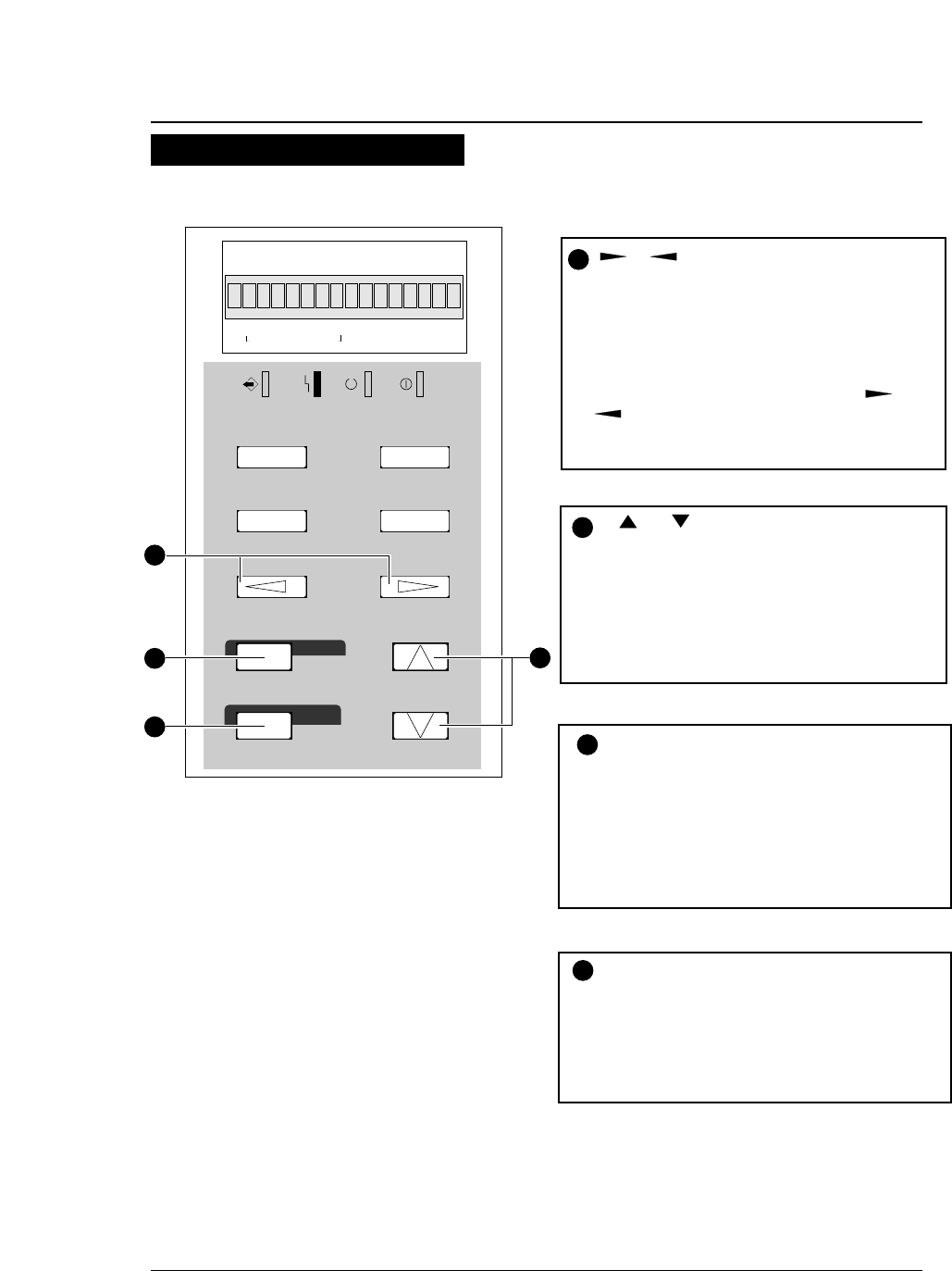
The keys shown below are used in the setup modes.
●
Operations in the setup modes
3-2 — 3. Setup options —
Keys used for setting
DATA ERROR ONLINE POWER
TEAR OFF ONLINE
FORM FEED
LINE FEED
REVERSE LF
TOF SET
QUALITY
PAPER FORM
RESET
SET UP
MICRO LF
MICRO RLF
EXIT
EXTENDED
ENTER
ALT
FORM
11. x 5
IN OUT
F.TR EAR
1
2
3
4
EJECT/LOAD
PAPER PATH
PAPER PATH
R511
Item selection keys
(Used with the LINE FEED or
REVERSE LF key.)
These keys are used to select items displayed
vertically in a menu. They change only the
display and do not change the setting.
ENTER key
To register a displayed menu item, press the
ENTER key. When the ENTER key is
pressed, the selected item is registered in the
printer and marked with an asterisk (*), and
the menu reappears.
EXIT key
Press the EXIT key to exit the panel setup
mode.
1
4
3
2
Menu selection keys
(Used with the EJECT/LOAD or
FORM FEED key.)
These keys are used to change the displayed
menus. They change only the display and do not
change the setting.
The menus is changed rapidly when the or
key is depressed and held for a second or
more.
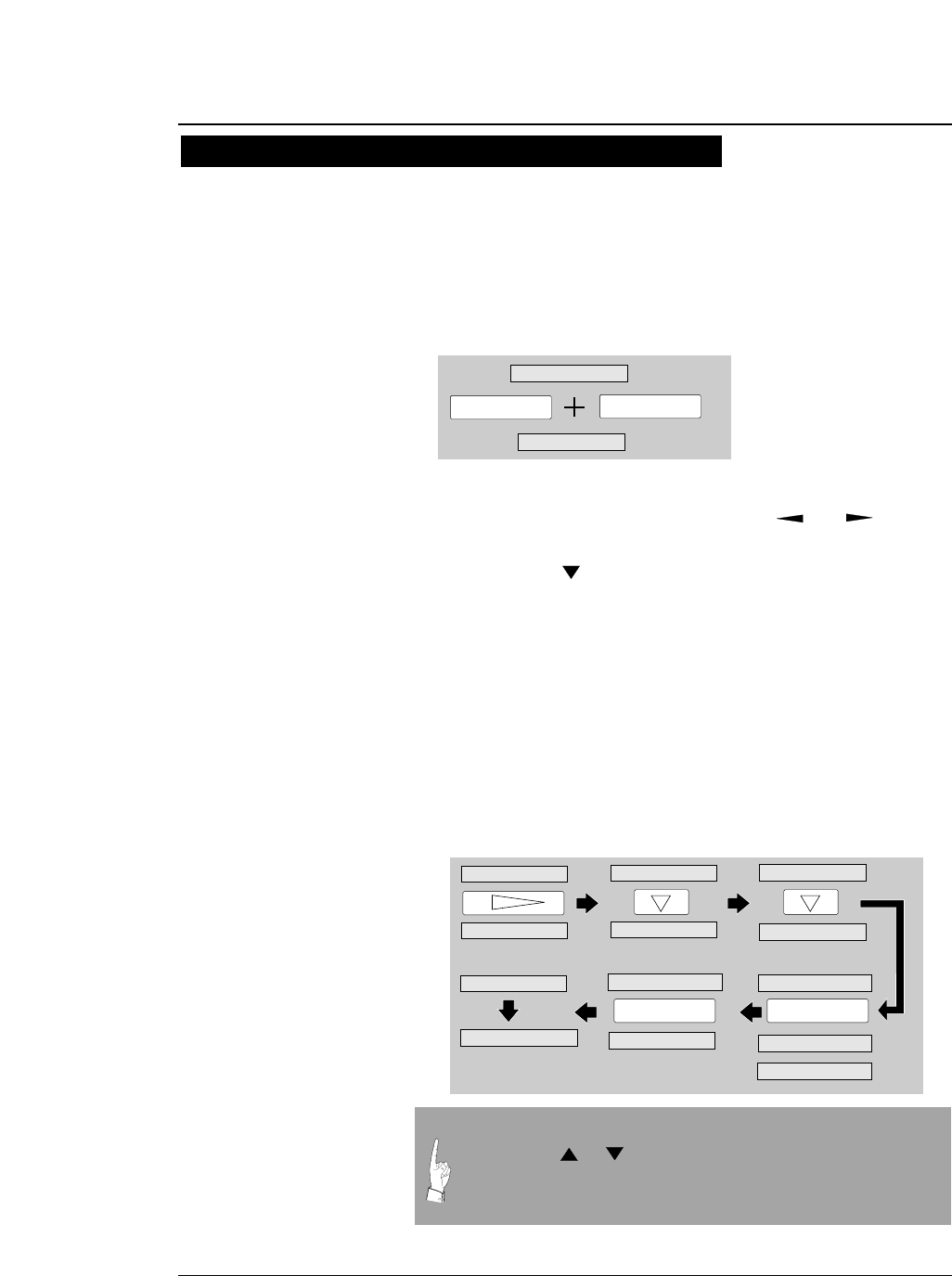
●
Operations in the setup modes
The following example shows how to select "OPTION: CSF" in the EXTENDED
SETUP MODE.
1. Press SET UP key while depressing the
ALT key.
2. Select #60 OPTION with the or key.
3. Press the key to display "OPTION: CSF"
on the LCD.
4. Press the ENTER key.
"CSF" is marked with an asterisk, indicating that the CSF is
selected.
5. Press the EXIT key. The setting is
automatically saved, and the printer is
initialized.
3-3
— 3. Setup options —
Setting example in the EXTENDED SETUP MODE
SET UP
20. EMULATION
ALT
F. TR REAR 11 x 15
ENTER
60. OPTION
NOT INSTALL*
OPTION: CSF
OPTION: CSF
OPTION: CSF *
20. EMULATION
INITIAL
60. OPTION
F. TR REAR 11 x 15 INITIAL
EXIT
60. OPTION
60. OPTION
NOT INSTALL*
In the SETUP MODE, after pressing the EXIT key select SAVE
YES by the or key and press the ENTER key. If SAVE
NO is selected, any changes made in the SETUP MODE are
erased when the printer power is turned off.
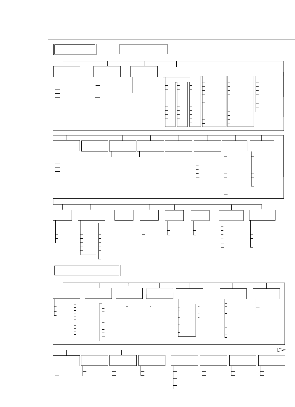
●
Setup mode summary(1)
3-4 — 3. Setup options —
NORMAL*
DARK 1
DARK 2
AUTO
15 INCH *
12 INCH
10 INCH
5 INCH
MULTIPART
1
5
PAPER WIDTH
(INCH SIZE)
+ n LINE
0 ≤ n ≤ 15
n=0*
TOP MARGIN
6
QUALITY
10
LQ *
NLQ
HQDR
DRAFT
S.D.
S.S.D.
FONT SELECT
11
ROMAN *
SANS SERIF
COURIER
PRESTIGE
SCRIPT
OCR-B
OCR-A
GOTHIC
ORATOR
ORATOR-S
SELECT SAVE
MEMORY
19
MEMO 1
MEMO 2
MEMO 3
MEMO 4
MEMO 5
MEMO 6
SETUP MODE
EPSON *
IBM
HP
EMULATION
20
CHARACTER
TABLE(IBM)
CHAR. SET 1*
CHAR. SET 2
23
CHARACTER
TABLE(EPSON)
21 24
EXTENDED SETUP MODE
ITALIC *
GRAPHIC
DOWNLOAD
CODE PAGE
USA *
FRANCE
GERMANY
U.K.
DENMARK
SWEDEN
ITALY
SPAIN
JAPAN
NORWAY
DENMARK2
SPAIN2
LATIN AMERICA
KOREA
TURKEY
LEGAL
CODE PAGE
25
AGM
(IBM)
26
NO *
YES
34
ZERO STYLE
30
NO-SLASHED *
SLASHED
TABULATION
31
2CHAR.
4 CHAR.
6 CHAR.
8 CHAR. *
10 CHAR.
12 CHAR.
FONT LOCK
33
NO *
YES
PITCH LOCK
NO *
YES
MEMO 1
MEMO 2
MEMO 3
MEMO 4
MEMO 5
MEMO 6
SELECT LOAD
MEMORY
20
7
+ n LINE
0 ≤ n ≤ 15
n=0*
BOTTOM
MARGIN
8
+ n COLUMN
0 ≤ n ≤ 63
n=0*
LEFT MARGIN
9
+ n COLUMN
0 ≤ n ≤ 63
n=0*
RIGHT
MARGIN
CHARACTER
TABLE (HP)
22
ROMAN-8 *
CODE PAGE
PC-8 DEN/NOR
LEGAL
SWEDEN 1
SWEDEN 2
SPAIN 1
FRANCE 1
GERMAN 1
U.K.
PORTGAL 1
NORWAY 1
NORWAY 2
IRV
ITALY
FRANCE 2
GERMAN 2
SPAIN 2
SPAIN 3
JAPAN
PORTGAL 2
27
CR SETTING
CR ONLY *
CR + LF
AUTOFEED
SIMPLE*
COMPO.
ACCENT CHR
29
LF ONLY
LF+CR *
LF SETTING
28
10 CPI *
12 CPI
15 CPI
16.7 CPI
17.1 CPI
20 CPI
24 CPI
PROPORTIONAL
CHARACTER
PITCH
12
141 %
200 %
400 %
600 %
800 %
1000%
1200 %
1400 %
1600 %
NATIONAL
FONT
TOF
ADJUSTMENT
TOP OF FORM
+ n/60 INCH
0 ≤ n ≤ 63
n=14*
3
AUTO: n CLICK
-2 ≤ n ≤ 5
FIX : n CLICK
-5 ≤ n ≤ 25
HEAD
ADJUSTMENT
2
AUTO 0 CLICK*
4
2
2.5
3
3.5
4
4.5
5
5.5
6
6.5
7
7.5
8
8.5
9
9.5
10
10.5
11 *
11.5
A3 p
A3 l
A4 p *
A4 l
A5 p
A5 l
LEDGER p
F4 p
F4 l
EXECUTIVE p
EXECUTIVE l
G.LETTER p
G.LETTER l
G.LEGAL p
G.LEGAL l
POST CARD p
POST CARD l
COM-6 p
12
12.5
13
13.5
14
14.5
15
15.5
16
16.5
COM-6 l
COM-10 p
COM-10 l
MONARCH p
MONARCH l
DL p
DL l
C5 p
C5 l
PAGE
LENGTH
INCH SIZE
REGULAR SIZE
LETTER p
LETTER l
H.LETTER p
H.LETTER l
LEGAL p
LEGAL l
PAGE LENGTH
LOCK
32
NO *
YES
437 *
850
857
858
860
861
863
865
BRASCII
ABICOMP
ISO8859-1
The astarisk (*) indicates
the factory default setting.
LF PITCH
13
6 LPI *
8 LPI
9 LPI
3 LPI
4 LPI
ZOOM IN/OUT
14
66 %
79 %
83 %
91 %
100 %*
116 %
120 %
15
PAPER
FASTENER
YES
NO *
FASTENER
16
PERFORA-
TION
HEAD LIFT
UP
YES
NO *
17
FANFOLD
FEED
FRICTION
YES *
NO
18
PAPER
QUALITY
GOOD
NO GOOD*
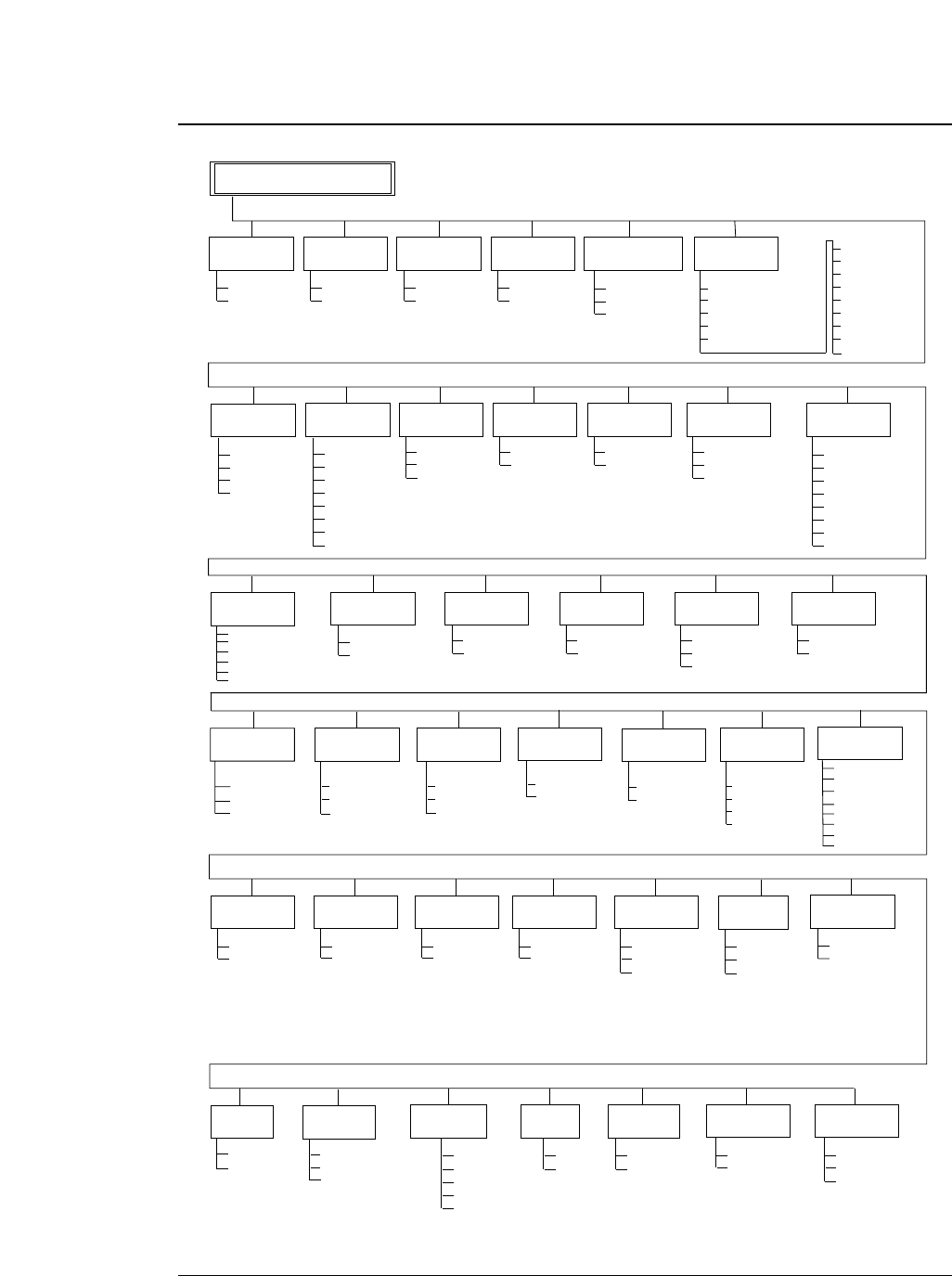
●
Setup mode summary(2)
3-5
— 3. Setup options —
73
EXTENDED SETUP MODE
1
0*
I/F
SELECT IN
ENABLE
71
STOP BIT
1 BIT *
2 BITS
74
SERIAL ERROR
77
PRINT "*" *
IGNORED
CTS ENABLE
78
NO *
YES
92
NO *
YES
DATA LATCH
TIMING
83
TYPE F. *
TYPE R.
PARALLEL *
SERIAL
AUTO
INTERFACE
70
PARITY BIT
NON *
EVEN
ODD
72
DATA LENGTH
8 BITS*
7 BITS
PROTOCOL
DTR*
XON/XOFF 1
XON/XOFF 2
ETX/ACK
75
CD ENABLE
79
NO *
YES
DSR ENABLE
80
NO *
YES
BUFFER SIZE
81
512KB*
8KB
128B
BUSY/ACK
TIMING
82
TYPE 1
TYPE 2 *
TYPE 3
PRINT
DIRECTION
90
PRE-DIRECTION
UNI-DIRECTION
BI-DIRECTION *
93
RESET KEY
LOCK
NO *
YES
SLEEP MODE
94
YES *
NO
QUALITY
LOCK
35
CHR TBL
LOCK
36
BARCODE/
ENLARGED CHAR
40
MODE 1 *
MODE 2
IGNORED
41
INDSTRIAL 2OF5
INTERLEAVED 2OF5
MATRIX 2OF5
CODABAR
CODE11
NO *
YES
NO *
YES
FF CODE
AT TOF
37
GRAPHIC
QUALITY
38
MODE 1
MODE 2 *
MODE 3
YES *
NO
AUTO SCROLL
62
NO SCROLL *
0.5 SEC
1 SEC
5 SEC
10 SEC
15 SEC
BARCODE
TYPE CODE39 *
CODE93
CODE128
EAN8
EAN13
UPC-A
UPC-E
POSTNET
ELEMENT
LARGE
CHAR. SIZE
43
SOFTWARE
SETUP
44
VALID *
IGNORED 1
IGNORED 2
SIZE: 1
SIZE: 2
SIZE: 4
SIZE: 8 *
SIZE: 12
SIZE: 16
SIZE: 24
SIZE: 32
BARCODE
SIZE
42
SIZE: 1 *
SIZE: 1.5
SIZE: 2
SIZE: 2.5
OPTION
60
PAPER PATH
61
NOT INSTALLED *
CSF
REAR TRACTOR
F.TR. ->REAR *
F.TR. ->TOP
MANUAL->FRONT
MANUAL->TOP
MANUAL->REAR
R.TR.->FRONT
CSF->FRONT
CSF->TOP
PAPER JAM
DETECTION
65
YES *
NO
P.OUT
DETECTION
63
YES *
NO
LF SPEED
66
NORMAL *
1/2
1/3
AUTO SCROLL
POSITION
67
ANY POS *
TOF ONLY
SKEW
DETECTION
64
YES *
NO
CHR TB2 HP
51
LINE-DRAW *
MATH-7
PCL MODE
50
PCL3 + *
PCL3
PCL3 + D
DISPLAY
LANGUAGE
91
ENGLISH *
DEUTSCH
FRANCAIS
ESPANOL
ITALIANO
38400 BPS
19200 BPS
9600 BPS*
4800 BPS
2400 BPS
1200 BPS
600 BPS
300 BPS
BAUD RATE
76
KEY
LOCK
ERROR
STATUS
YES *
NO
84
SETUP MENU
LIST
95
PATH & FORM
EXTEND
ALL SETUP
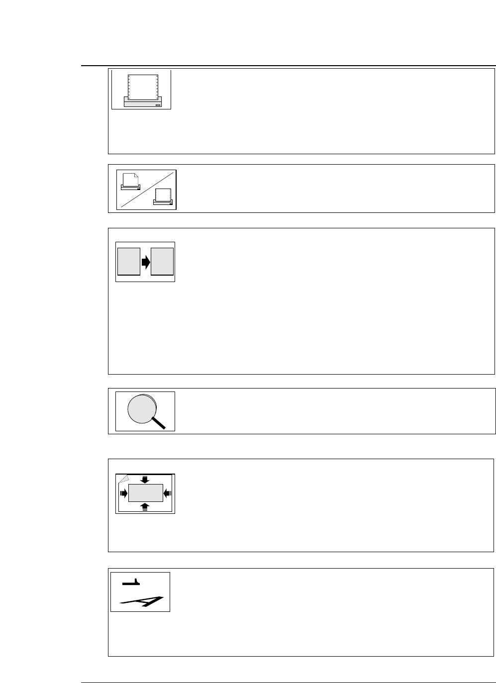
Printing Factory Default Setting Page
#01 : MULTIPART ➞ NORMAL 3-8
#02 : HEAD ADJUSTMENT ➞ AUTO 0 CLICK 3-9
#15 : PAPER FASTENER NO 3-22
#16 : PERFORATION NO 3-22
#17 : FANFOLD FEED YES 3-23
#18 : PAPER QUALITY NOT GOOD 3-23
#66 : LF SPEED NORMAL 3-44
Form selection
#61 : PAPER PATH ➞ F.Tr.->REAR 3-40
Character
#10 : QUALITY ➞ LQ 3-17
#11 : FONT SELECT ➞ ROMAN 3-18
#12 : CHARACTER PITCH ➞ 10CPI 3-19
#21 : CHARACTER TABLE (HP) ➞ ROMAN-8 3-25
#22 : CHARACTER TABLE (EPSON) ➞ ITALIC 3-26
#23 : CHARACTER TABLE (IBM) ➞ SET 1 3-26
#24 : NATIONAL FONT (EPSON) ➞ U.S.A. 3-27
#25 : CODE PAGE ➞ 437 3-28
#26 : AGM (Alternate Graphics Mode) (IBM) ➞ NO 3-28
#29 : ACCENT CHR ➞ SIMPLE 3-30
#30 : ZERO STYLE ➞ NO SLASHED 3-30
#38 : GRAPHIC QUALITY ➞ MODE2 3-35
#51 : CHRACTER TABLE 2 (HP) ➞ LINE DRAW 3-41
Zooming
#14 : ZOOM IN/OUT ➞ 100% 3-21
Printing start position and printing area
#03 : TOF ADJUSTMENT ➞ 14/60 inch 3-10
#04 : PAGE LENGTH ➞ (Memo1
~
3)11inch (Memo4
~
6)A4 p 3-11
#05 : PAPER WIDTH ➞ (Memo1
~
3)15 inch (Memo4
~
6)10inch 3-12
#06 : TOP MARGIN ➞ 0 LINE 3-13
#07 : BOTTOM MARGIN ➞ 0 LINE 3-14
#08 : LEFT MARGIN ➞ 0 COL 3-15
#09 : RIGHT MARGIN ➞ 0 COL 3-16
Line feed and carriage return
#13 : LF PITCH ➞ 6 LPI 3-20
#27 : CR SETTING ➞ CR ONLY 3-29
#28 : LF SETTING ➞ LF + CR 3-29
#31 : TABULATION ➞ 8 CHAR 3-31
#37 : FF CODE AT TOF ➞ YES 3-34
#90 : PRINT DIRECTION ➞ BI-DIRECTION 3-55
●
Factory default setting
3-6 — 3. Setup options —
aa
A
A
Lock function Factory Default Setting Page
#32 : PAGE LENGTH LOCK ➞ NO 3-31
#33 : FONT LOCK ➞ NO 3-32
#34 : PITCH LOCK ➞ NO 3-32
#35 : QUALITY LOCK ➞ NO 3-33
#36 : CHARACTER TABLE LOCK ➞ NO 3-33
#92 : KEY LOCK ➞ NO 3-56
#93 : RESET KEY LOCK ➞ NO 3-56
Bar code and enlarged character
#40 : BARCODE/ENLARGED CHARACTER ➞ MODE 1 3-36
#41 : BARCODE TYPE ➞ CODE 39 3-37
#42 : BARCODE SIZE ➞ 1 3-39
#43 : ENLARGED CHARACTER SIZE ➞ 8 3-39
Operation condition
#19 : SELECT SAVE MEMORY ➞ MEMO 1 3-24
#20 : SELECT LOAD MEMORY ➞ MEMO 1 3-24
#20 : EMULATION ➞ EPSON 3-25
#44 : SETUP COMMAND ➞ VALID 3-40
#50 : PCL MODE (HP) ➞ PCL 3+ 3-40
#60 : OPTION ➞ NOT INSTALL 3-41
#62 : AUTO SCROLL ➞ NO SCROLL 3-42
#63 : P.OUT DETECTION ➞ YES 3-43
#64 : SKEW DETECTION ➞ YES 3-43
#65 : PAPER JAM ➞ YES 3-44
#67 : AUTO SCROLL POSITION ➞ ANY POS 3-45
#91 : DISPLAY LANGUAGE ➞ ENGLISH 3-55
#94 : SLEEP MODE ➞ YES 3-57
#95 : SETUP MENU LIST ➞ PATH & FORM 3-57
Interface condition
#70 : INTERFACE ➞ PARALLEL 3-46
#71 : SELECT IN ENABLE ➞ 0 3-47
#72 : PARITY BIT (SERIAL I/F) ➞ NON 3-47
#73 : DATA LENGTH (SERIAL I/F) ➞ 8 BITS 3-48
#74 : STOP BIT (SERIAL I/F) ➞ 1 BIT 3-48
#75 : PROTOCOL (SERIAL I/F) ➞ DTR 3-49
#76 : BAUD RATE (SERIAL I/F) ➞ 9600 B 3-49
#77 : SERIAL ERROR (SERIAL I/F) ➞ PRINT 3-50
#78 : CTS ENABLE (SERIAL I/F) ➞ NO 3-50
#79 : CD ENABLE (SERIAL I/F) ➞ NO 3-51
#80 : DSR ENABLE (SERIAL I/F) ➞ NO 3-51
#81 :
BUFFER SIZE
➞ 64KB 3-52
#82 : BUSY/ACK TIMING (PARALLEL I/F) ➞ TYPE 2 3-53
#83 : DATA LATCH TIMING (PARALLEL I/F) ➞ TYPE F. 3-53
#84 : ERROR STATUS (PARALLEL I/F) ➞ YES 3-54
●
Factory default setting
3-7
— 3. Setup options —
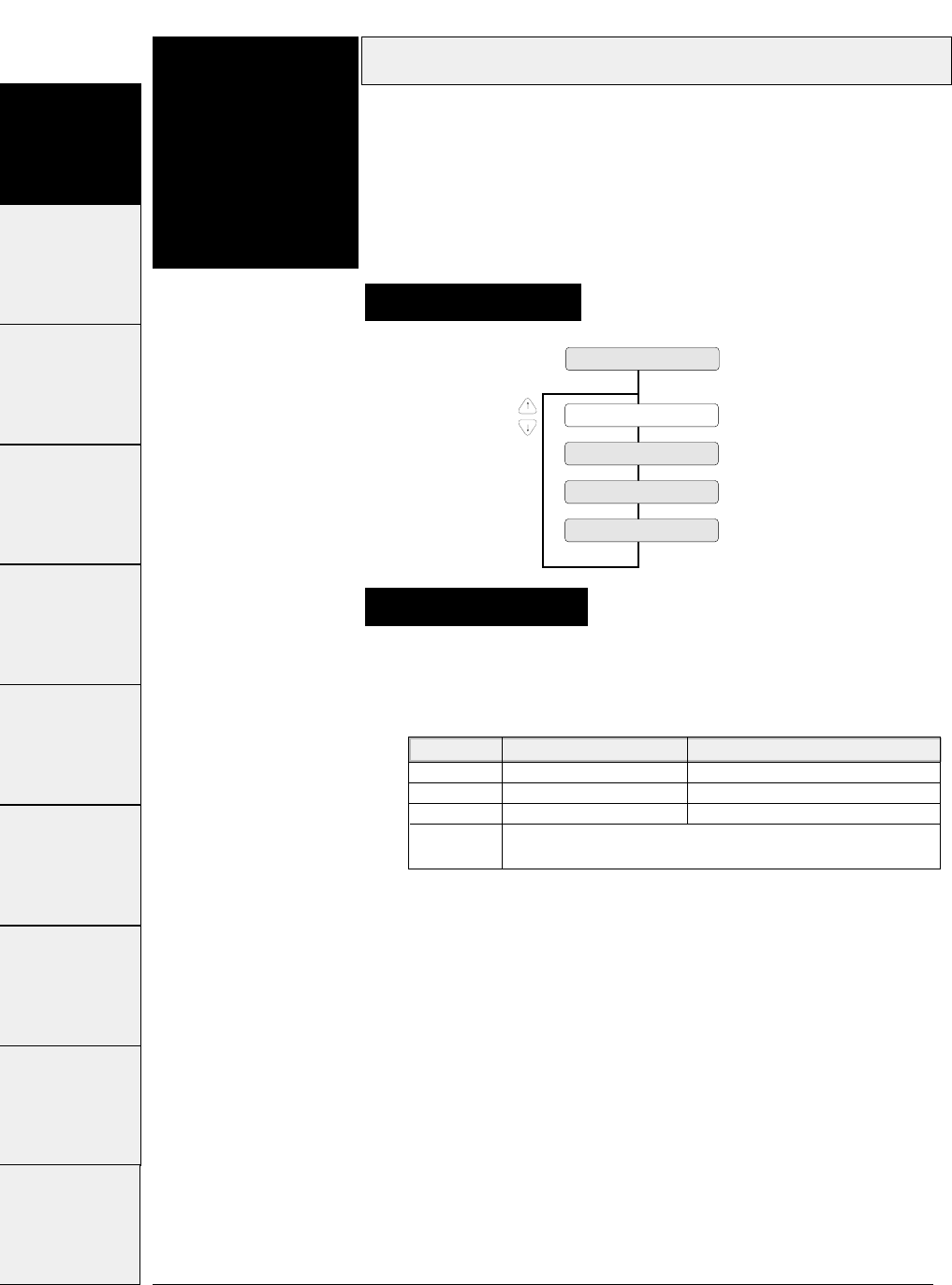
Printing capabilities on multipart paper are selectable as shown below.
Multipart
3-8 — 3. Setup options —
#1~#9 #10 ~ #20 #20 ~ #29 #30 ~ #38 #40 ~ #44 #50, #51 #60 ~ #67 #70 ~ #79 #80 ~ #84
Function
#01
1 MULTIPART
COPY: NORMAL
COPY: DARK 1
COPY: DARK 2
COPY: AUTO
Supplementary notes
This function improves the printing capability on
multipart paper.
Use multipart paper consisting of an original plus eight non-
carbon sheets or copying paper up to 0.59 mm thick.
Setting procedures
#90 ~ #95
LCD display LQ Draft
NORMAL ORIGINAL + 5 ORIGINAL + 4
DARK1 ORIGINAL + 7 ORIGINAL + 7
DARK1 ORIGINAL + 8 ORIGINAL + 8
AUTO Automatically swiches Normal, Dark 1, or Dark 2 according
to the paper thickness.
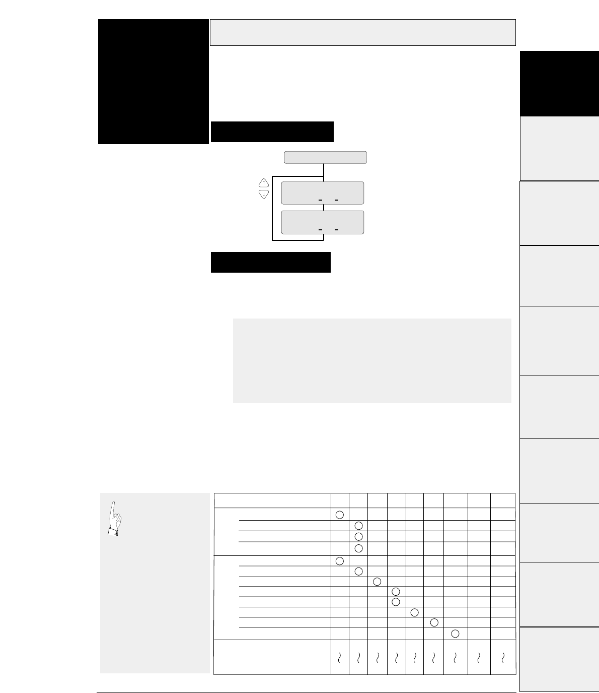
3-9
— 3. Setup options —
Head adjustment
Function
#02 This function adjusts the gap between the print head
and platen.
This function has FIX and AUTO modes: The gap is fixed in the
FIX mode, and the gap is automatically adjusted in the AUTO
mode.
2 HEAD ADJUST
FIX : n CLICK
AUTO : n CLICK
-2 < n < +5
-5 < n < +25
DEFAULT : AUTO : 0 CLICK
#1~#9
#10 ~ #20
#20 ~ #29
#30 ~ #38
#40 ~ #44
#50, #51
#70 ~ #79
#80 ~ #84
Setting procedures
#90 ~ #95
In the AUTO mode,
the gap is
automatically
adjusted every time
fanfold paper or
manually-inserted paper is
loaded. When CSF is used,
automatic paper thickness
adjustment is performed
when the paper is first
loaded. Thereafter,
automatic paper thickness
adjustment is performed
when the next sheet is fed
if printing is not performed
within 3 to 4 seconds after
the paper is ejected.
The smaller the number, the
smaller the gap between the
head and platen.
Ream weight: 55 to 90 kg
Ream weight: 90 to 135 kg
Ream weight: 180 kg
Postcard
Total paper thickness (mm)
-1 ~ 1
0.08 0.16 0.24 0.32 0.4 0.48 0.56 0.64 0.72
0.16 0.24 0.32 0.4 0.48 0.56 0.64 0.72 0.8
(Paper
weight
: 34 kg)
1~ 3 3~ 5 5 ~ 77~ 9 9~ 11 11~ 13 13~ 15 15~ 17
Paper type/fixed click position
Cut
sheet
Multipart
paper
2sheets
3sheets
4sheets
5sheets
6sheets
7sheets
8sheets
9sheets
#60 ~ #67
Every click changes the gap by 0.04 mm.
The recommended gap for 70 kg 1P paper is at the 0 click
position in the FIX mode.
●AUTO mode
In the AUTO mode, the gap between the print head and
platen is automatically adjusted according to the paper
thickness. Since the most appropriate gap differs with the
type of paper, select the proper position between -2 and +5
according to the printing results.
●FIX mode
The gap between the print head and platen is fixed as
specified.
Select the proper position according to the paper type and
thickness by referring to the table below.
Supplementary notes

The TOF position is adjusted in units of 1/60 inch. It can be
adjusted between 0/60 inch (minimum) and 63/60 inches
(maximum) from the end of paper.
TOF adjustment
3-10 — 3. Setup options —
Function
#03
3 TOF ADJUST
TOP: + n /60 IN The value may be changed with the and keys.
0 ≤ n ≤ 63
DEFAULT : n=14
This function specifies the top of form (TOF)
position.
When paper is loaded, the printer detects the end of the paper and
determines the printing start position based on the detected paper
end. That position is the top of the form (TOF).
Setting procedures
Supplementary notes
Though the TOF position can be set from 0/60
inch (0 mm), paper may jam if it is set to a
value between 0/60 inch to 9/60 inch. Normally, it is
recommended that the TOF position be set to 14/60 inch
(approximately 6 mm) from the paper end.
Caution
#1~#9 #10 ~ #20 #20 ~ #29 #30 ~ #38 #40 ~ #44 #50, #51 #60 ~ #67 #70 ~ #79 #80 ~ #84 #90 ~ #95
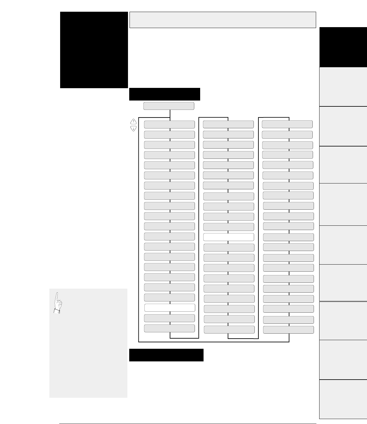
3-11
— 3. Setup options —
Page length
Function
#04 This function specifies the page length of the form
to be used.
Thirty types of page lengths, from 2 to 16.5 inches in 0.5 inch steps,
plus seventeen standard sizes are available as shown below.
When fanfold paper is used, the page length set here is used to define
the perforation.
The printer loads paper, it regards the end of the paper as the
perforation. The TOF (top-of-form) position is determined from the
end of the paper based on a preset TOF value.
4 PAGE LENGTH
PAGE: 2 IN
PAGE: 2.5 IN
PAGE: 3 IN
PAGE: 3.5 IN
PAGE: 4 IN
PAGE: 4.5 IN
PAGE: 5 IN
PAGE: 5.5 IN
PAGE: 6 IN
PAGE: 6.5 IN
PAGE: 7 IN
PAGE: 7.5 IN
PAGE: 8 IN
PAGE: 8.5 IN
PAGE: 11 IN
PAGE: 9 IN
PAGE: 9.5 IN
PAGE: 10 IN
PAGE: 10.5 IN
PAGE: 11.5 IN
PAGE: 12 IN
PAGE: 12.5 IN
PAGE: 13 IN
PAGE: 13.5IN
PAGE: 14 IN
PAGE: 14.5 IN
PAGE: 15 IN
PAGE: 15.5 IN
PAGE: 16 IN
PAGE: 16.5 IN
SIZE: A3 p
SIZE: A3 l
SIZE: A4 l
SIZE: A5 p
SIZE: A5 l
SIZE: G.LETTER p
SIZE: G.LETTER l
SIZE: EXECUT p
SIZE: EXECUT l
SIZE: LETTER p
SIZE: LETTER l
SIZE: H.LETTER p
SIZE: H.LETTER l
SIZE: LEGAL p
SIZE: LEGAL l
SIZE: F4 l
SIZE: POST C. p
SIZE: POST C. l
SIZE: LEDGER p
SIZE: F4 p
SIZE: G.LEGAL p
SIZE: G.LEGAL l
SIZE: COM-6 p
SIZE: COM-6 l
SIZE: COM-10 p
SIZE: COM-10 l
SIZE: MONARCH p
SIZE: MONARCH l
SIZE: DL p
SIZE: DL l
SIZE: C5 p
SIZE: C5 l
SIZE: A4 p
Supplementary notes
Setting procedures
If the PAGE LENGTH
LOCK option is set to
NO in the EXTENDED
SETUP MODE, the
page length can be
changed by a software
command. The values
available on the menu
serve as the default
values. If the PAGE
LENGTH LOCK option
is set to YES in the
EXTENDED SETUP
MODE, any software
command to change the
page length is ignored.
#1~#9
#10 ~ #20
#20 ~ #29
#30 ~ #38
#40 ~ #44
#50, #51
#70 ~ #79
#80 ~ #84
#90 ~ #95 #60 ~ #67
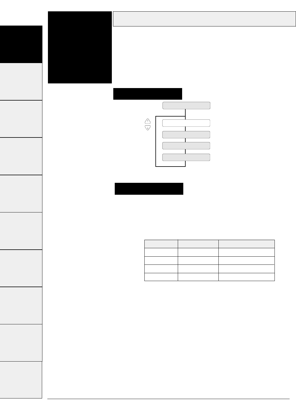
The following table shows the relationship between the paper width
settings in inches and the number of columns printable on each line,
when characters are printed at 10 cpi.
Paper width
3-12 — 3. Setup options —
Function
#05
5 PAPER WIDTH
WIDTH : 15 IN
WIDTH : 12 IN
WIDTH : 10 IN
WIDTH : 5 IN
Supplementarynotes
This function specifies the width of fanfold paper.
This function specifies the width of fanfold paper in inches.
Setting procedures
Display Paper width Max. columns/line
15 IN 15 inches 136
12 IN 12 inches 106
10 IN 10 inches 80
5 IN 5 inches 36
#1~#9 #10 ~ #20 #20 ~ #29 #30 ~ #38 #40 ~ #44 #50, #51 #60 ~ #67 #70 ~ #79 #80 ~ #84 #90 ~ #95
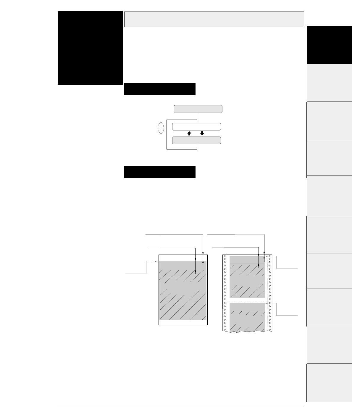
3-13
— 3. Setup options —
Top margin
Function
#06 This function specifies the length of the area at the top
of the paper where printing is disabled in units of 6 LPI
from the TOF position.
6 TOP MARGIN
T.M. : 0 LINE
n = 0 ~ 15
T.M. : 15 LINE
Setting procedures
Supplementary notes
The top margin is specified in units of 6 LPI (lines per inch)
within the range from 0 (minimum) to 15 (maximum) from the
TOF position.
0/60 to 63/60 inches
(#3 TOF ADJUSTMENT on SETUP MENU)
0/60 to 63/60 inches
(#3 TOF ADJUSTMENT on SETUP MENU)
TOF
TOF
TOF
0 to 15 lines
(#6 TOP MARGIN on SETUP MENU)
0 to 15 lines
(#6 TOP MARGIN on SETUP MENU)
Printable area when top
margin is specified.
Printable area when top
margin is specified.
Printable area when top
margin is specified.
#1 ~ #9
#10 ~ #20
#20 ~ #29
#30 ~ #38
#40 ~ #44
#50, #51
#70 ~ #79
#80 ~ #84
#90 ~ #95 #60 ~ #67
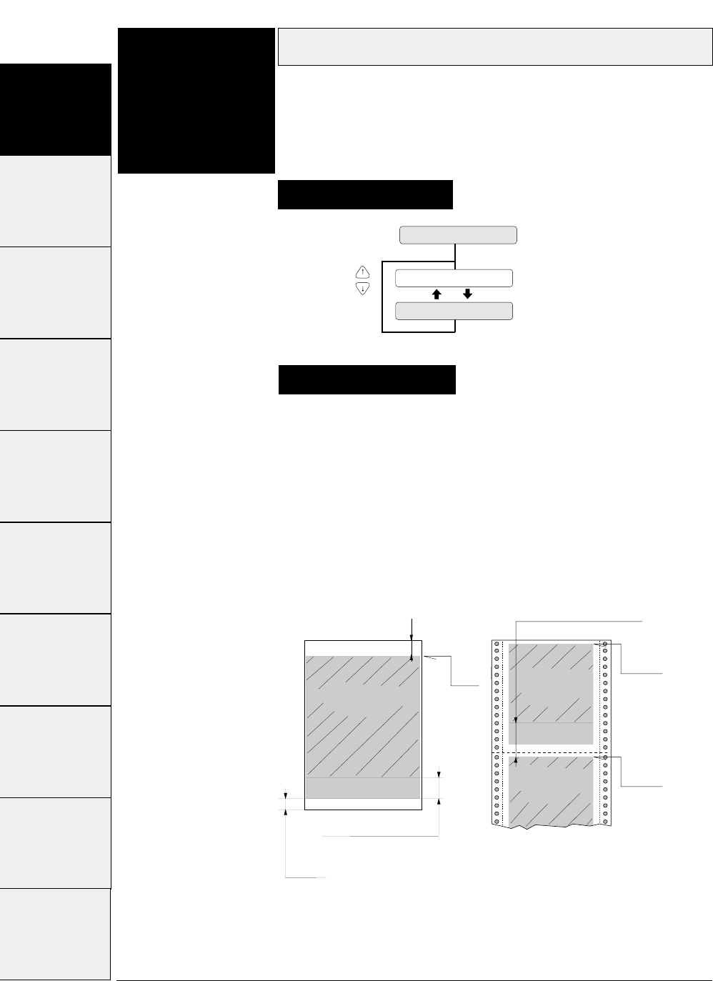
The bottom margin of fanfold paper is specified in units of 6
LPI (lines per inch) within the range from 0 to 15 from the
TOF position of the following page.
The bottom margin of cut sheet paper is specified within the
range from 0 to 15 from the bottom of the printable area.
Bottom margin
3-14 — 3. Setup options —
Function
#07 This function specifies the length of the area at the
bottom of the paper where printing is disabled in units
of 6 LPI from the TOF position of the following page.
Supplementary notes
Setting procedures
7 BOTTOM MARGIN
B.M. : 0 LINE
n = 0 ~ 15
B.M. : 15 LINE
TOF
TOF
TOF
4 mm
0/60 to 63/60 inches
(#3 TOF ADJUSTMENT on SETUP MENU)
0 to 15 lines
(#7 BOTTOM MARGIN on SETUP MENU)
0 to 15 lines
(#7 BOTTOM MARGIN on SETUP MENU)
Printable area when
bottom margin is specified.
Printable area when
bottom margin is
specified.
Printable area when
bottom margin is
specified.
#1~#9 #10 ~ #20 #20 ~ #29 #30 ~ #38 #40 ~ #44 #50, #51 #60 ~ #67 #70 ~ #79 #80 ~ #84 #90 ~ #95
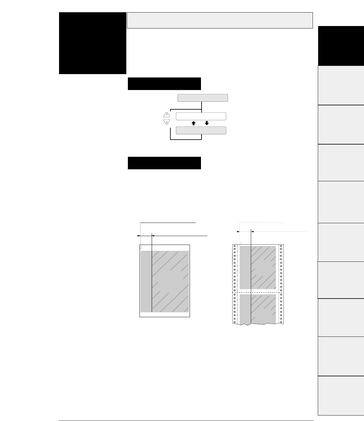
3-15
— 3. Setup options —
The left margin is specified by the number of columns (1/10")
within the range from 0 to 63 columns from the left end of the
printable area as shown below.
Left margin
Function
#08
Supplementary notes
Setting procedures
This function specifies the length of the area on the left
side of the paper where printing is disabled from the
left end of the printable area.
8 LEFT MARGIN
L.M. : 0 COL
n = 0 ~ 63
L.M. : 63 COL
Printable area
when left margin
is specified.
Printable area
when left margin
is specified.
Printable area
when left margin
is specified.
0 to 63 characters 0 to 63 characters
(#8 LEFT MARGIN on SETUP MENU) (#8 LEFT MARGIN on SETUP
MENU)
Left end of printable area Left end of printable area
#1~#9
#10 ~ #20
#20 ~ #29
#30 ~ #38
#40 ~ #44
#50, #51
#70 ~ #79
#80 ~ #84
#90 ~ #95 #60 ~ #67
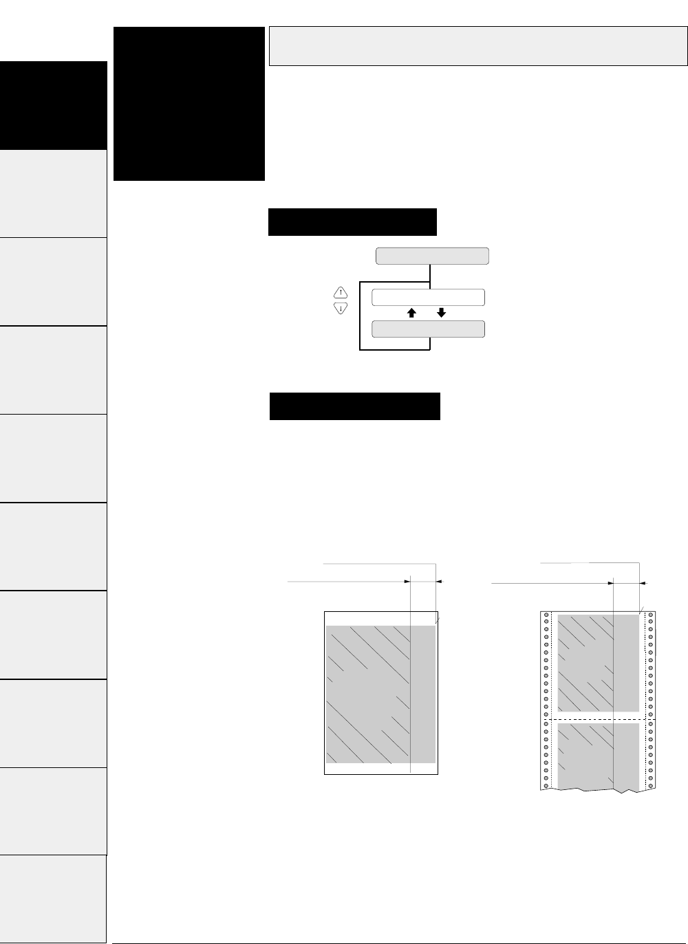
The right margin by specified in the number of columns
(1/10") within the range from 0 to 63 from the right end of the
printable area as shown below.
3-16 — 3. Setup options —
Function
#09 This function specifies the length of the area on the
right side of the paper where printing is disabled from
the right end of the printable area.
Setting procedures
Right margin
9 RIGHT MARGIN
R.M. : 0 COL
n = 0 ~ 63
R.M. : 63 COL
Supplementary notes
Right end of printable areaRight end of printable area
Printable area
when right margin
is specified.
0 to 63 characters 0 to 63 characters
(#9 RIGHT MARGIN on SETUP
MENU) (#9 RIGHT MARGIN on SETUP
MENU)
Printable area
when right
margin
is specified.
Printable area
when right
margin
is specified.
#1 ~ #9 #10 ~ #20 #20 ~ #29 #30 ~ #38 #40 ~ #44 #50, #51 #60 ~ #67 #70 ~ #79 #80 ~ #84 #90 ~ #95
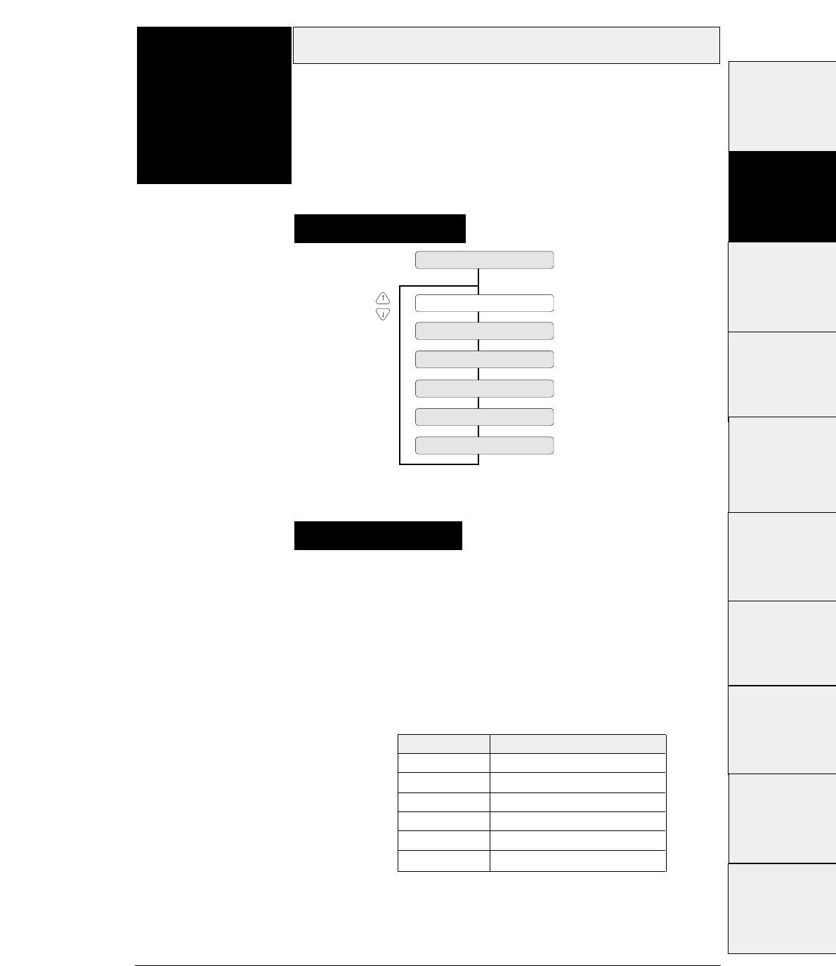
3-17
— 3. Setup options —
Character quality
Function
#10 This function specifies character quality.
This option has the same function as the QUALITY key (i.e.,
EJECT/LOAD key while depressing ALT key). Priority is given to
the most recent setting made with the QUALITY key or in the
SETUP MODE.
When "LQ" is not selected, 180/36/120/240-dpi graphics are
printed at high speed with lower bit density.
10 QUALITY
QLTY: LQ
QLTY: NLQ
QLTY: DRAFT
QLTY: S.D.
QLTY: S.S.D
QLTY: HQDR
Supplementary notes
Setting procedures
QUALITY Graphic speed
LQ Normal
NLQ High speed 1
HQDR High speed 2
DRAFT High speed 2
S. D. High speed 2
S. S. D. High speed 2
#1 ~ #9
#10 ~ #20
#20 ~ #29
#30 ~ #38
#40 ~ #44
#50, #51
#70 ~ #79
#80 ~ #84
#90 ~ #95 #60 ~ #67
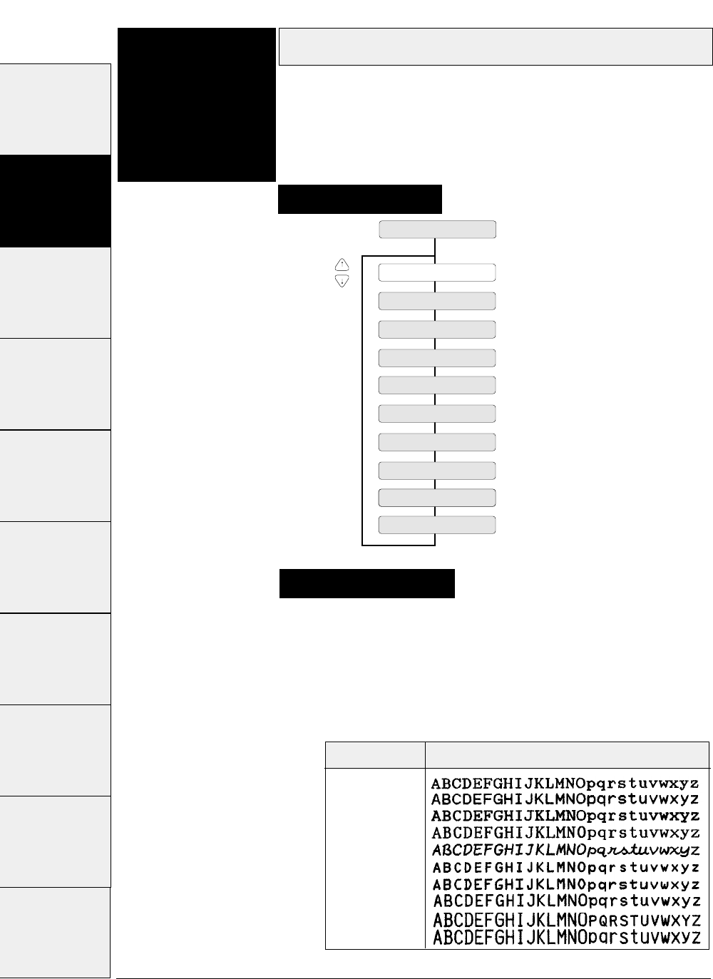
Setting procedures
Supplementary notes
Character font
3-18 — 3. Setup options —
Function
#11 This function specifies the typeface of the font
characters.
The following ten fonts are available: Roman, Sans Serif,
Courier, Prestige, Script, OCR-B, OCR-A, Gothic, Orator, and
Orator-s.
FONT : ROMAN
FONT : S. SERIF
FONT : COURIER
FONT : PRESTIGE
FONT : SCRIPT
FONT : OCR-B
FONT : OCR-A
FONT : GOTHIC
FONT : ORATOR
FONT : ORATORs
11 FONT SELECT
If the FONT LOCK option is set to NO in the EXTENDED
SETUP MODE, the font can be changed by a software
command. The font selected on the menu serves as the
default font.
If the FONT LOCK option is set to YES in the EXTENDED
SETUP MODE, the currently selected font cannot be
changed by a software command.
Font Printing sample
ROMAN
SANS SERIF
COURIER
PRESTIGE
SCRIPT
OCR-B
OCR-A
GOTHIC
ORATOR
ORATOR-S
#1~#9 #10 ~ #20 #20 ~ #29 #30 ~ #38 #40 ~ #44 #50, #51 #60 ~ #67 #70 ~ #79 #80 ~ #84 #90 ~ #95
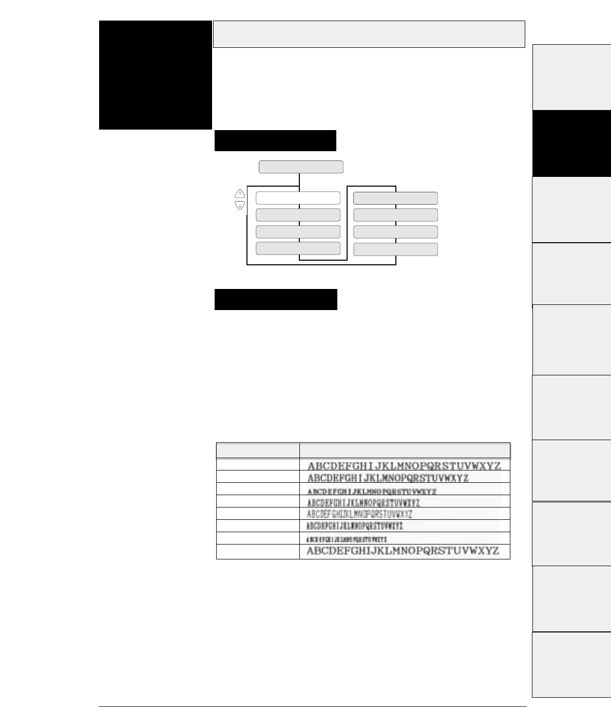
If the PITCH LOCK option is set to NO in the EXTENDED SETUP
MODE, the character pitch can be changed by a software
command. The pitch selected on the menu serves as the default
pitch.
If the PITCH LOCK option is set to YES in the EXTENDED SETUP
MODE, the currently selected pitch cannot be changed by a
software command.
3-19
— 3. Setup options —
Character pitch
Function
#12
PITCH : 10 CPI
12 CHARACTER PICH
PITCH : 12 CPI
PITCH : 15 CPI
PITCH : 20 CPI
PITCH : 24CPI
PITCH : 16.7 CPI PITCH : PROP.
PITCH : 17.1 CPI
Supplementary notes
Setting procedures
This function specifies the character pitch.
The available pitches are: 10 cpi, 12 cpi, 15 cpi, 16,7 cpi, 17.1 cpi,
20 cpi, 24 cpi, and proportional.
Character pitch Printing sample
10 cpi
12 cpi
15 cpi
16.7 cpi
17.1 cpi
20 cpi
24 cpi
LQ Proprtional
#1~#9
#10 ~ #20
#20 ~ #29
#30 ~ #38
#40 ~ #44
#50, #51
#70 ~ #79
#80 ~ #84
#90 ~ #95 #60 ~ #67
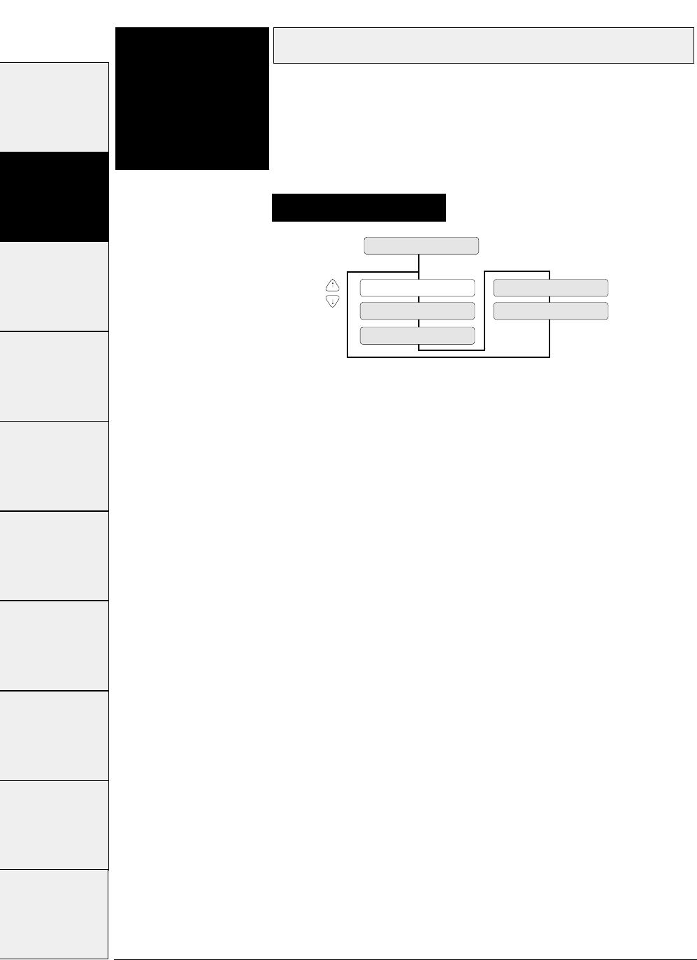
Line feed pitch
3-20 — 3. Setup options —
Function
#13 This function specifies the line feed pitch as shown
below.
LF: 6 LPI...... 1/6
inch pitch
LF: 3 LPI...... 1/3
inch pitch
LF: 8 LPI...... 1/8
inch pitch
LF: 4 LPI...... 1/4
inch pitch
LF: 9 LPI...... 1/9
inch pitch (LPI = Line Per Inch)
13 LF PITCH
LF: 6 LPI
LF: 8 LPI
LF: 9 LPI
LF: 3 LPI
LF: 4 LPI
Setting procedures
#1 ~ #9 #10 ~ #20 #20 ~ #29 #30 ~ #38 #40 ~ #44 #50, #51 #60 ~ #67 #70 ~ #79 #80 ~ #84 #90 ~ #95
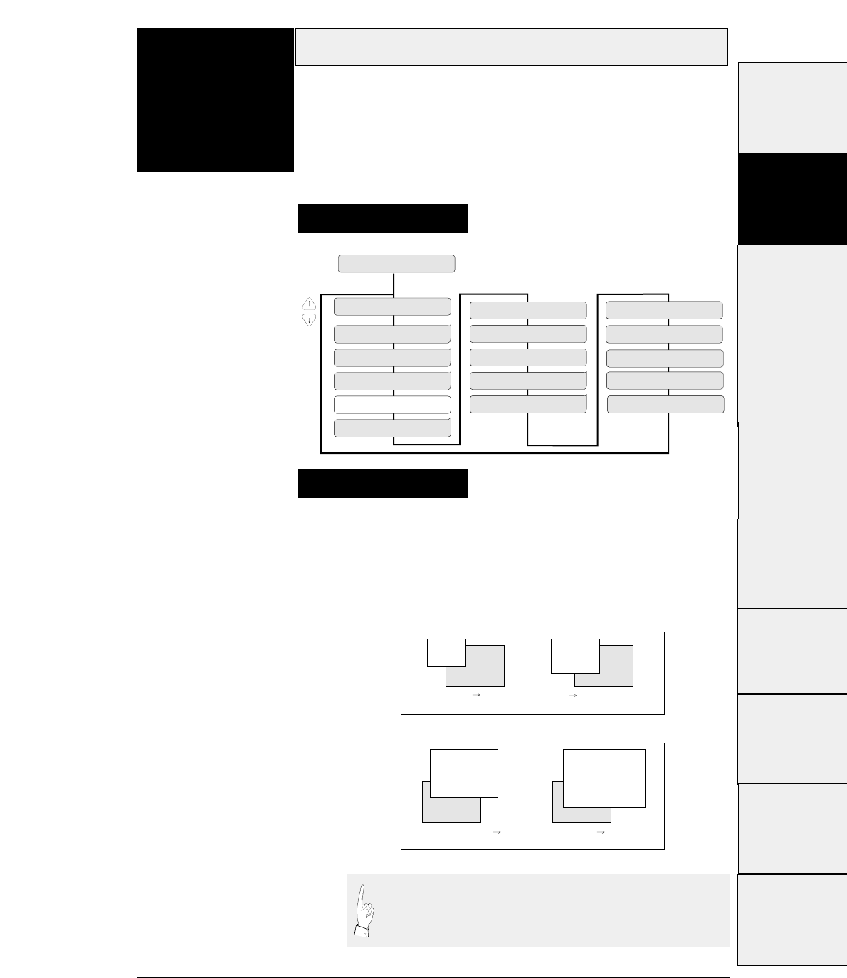
3-21
— 3. Setup options —
Documents are enlarged or reduced vertically and
horizontally by the degree of magnification specified with this
function. The following shows the frequently-used
magnifications for reference.
Enlarging/Reducing print
Function
#14
14 ZOOM IN/OUT
ZOOM OUT: 66 %
NO ZOOM: 100 %
ZOOM IN : 116 %
ZOOM OUT: 79 %
ZOOM OUT: 83 %
ZOOM OUT: 91 %
ZOOM IN: 600 %
ZOOM IN: 400 %
ZOOM IN: 200 %
ZOOM IN: 141 %
ZOOM IN: 120 % ZOOM IN: 800 %
ZOOM IN: 1000 %
ZOOM IN: 1200 %
ZOOM IN: 1400 %
ZOOM IN: 1600 %
Supplementary notes
Setting procedures
This function specifies the magnification enlargement
(zoom in) or reduction (zoom out).
It can enlarge or reduce data as needed according to the form size.
It is used, for example, to print documents prepared for the A4
paper on A3 paper.
66% 83%
116% 141%
A3 A4 A4 EXECUTIVE
EXECUTIVE(p) A4(p) A4(p) A3(p)
ZOOM OUT
ZOOM IN
(p)
(P) : Portrait
(Enlargement)
(Reduction)
The magnification displayed on the LCD has some
allowance. Enlarged or reduced characters are printed in a
different font from the specified font.
#1 ~ #9
#10 ~ #20
#20 ~ #29
#30 ~ #38
#40 ~ #44
#50, #51
#70 ~ #79
#80 ~ #84
#90 ~ #95 #60 ~ #67
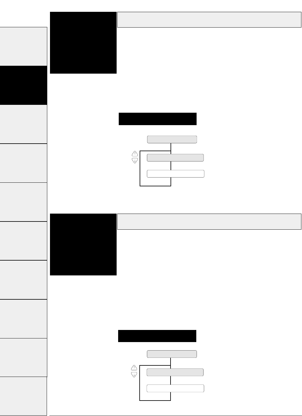
Paper fastener mode setting
3-22 — 3. Setup options —
Function
#15 This function sets the mode for stable paper feeding with
multipart fanfold paper bound by paper fasteners.
When the multipart fanfold paper is bound by paper fasteners or
paper staples rather than glue, paper slippage or paper jam error
may occur. When paper is fed while the print head is stopped on a
paper fastener, the fastener will become a load and normal paper
feeding will be disabled. When YES is selected, the print head does
not stop on a paper fastener.
Perforation head-up mode setting
Function
#16 This setting is effective when the perforation peak exceeds the
range which permits normal paper feeding.
When the perforation peak of the paper which is spread on a flat
surface is 1.0 mm or more, paper slippage or paper jam error may
occur. This will result in a stress when the printi head passes over
the perforation, and normal paper feeding will be disabled.
When YES is selected, the gap between the print head and the
platen is widen while the paper is feeding within 0.5 inch of the
perforation.
Setting procedures
Setting procedures
15 PAPER FASTENER
FASTENER MODE : YES
FASTENER MODE : NO
16 PERFORATION
HEAD LIFT UP : YES
HEAD LIFT UP : NO
#1 ~ #9 #10 ~ #20 #20 ~ #29 #30 ~ #38 #40 ~ #44 #50, #51 #60 ~ #67 #70 ~ #79 #80 ~ #84 #90 ~ #95
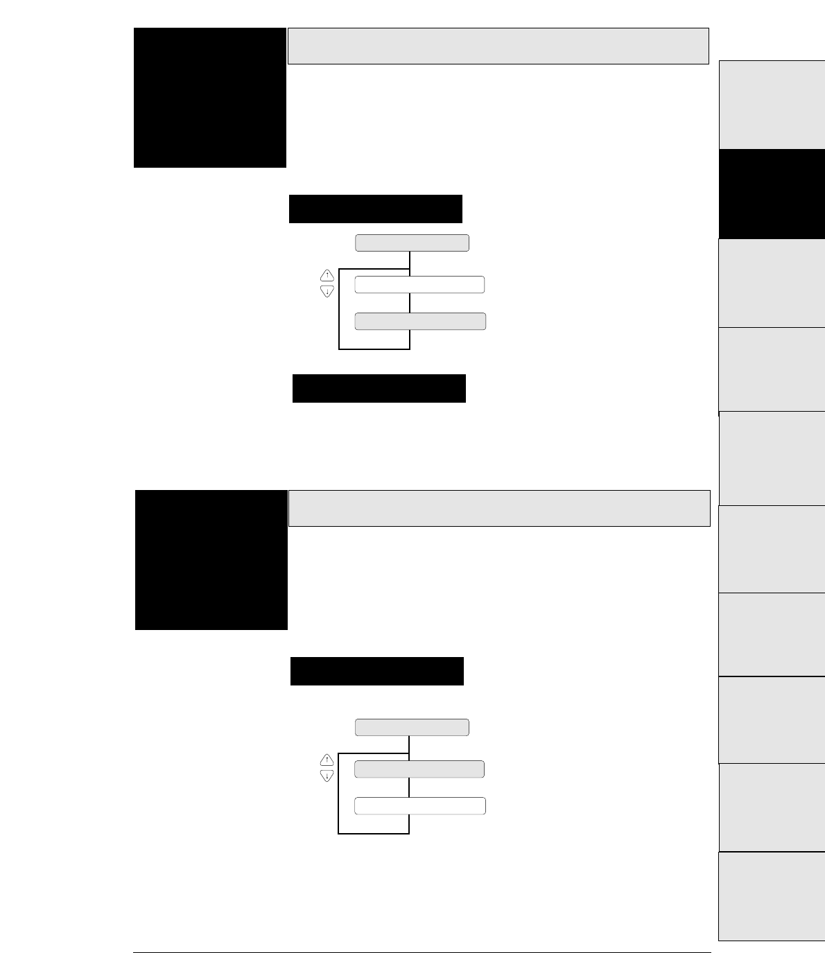
3-23
— 3. Setup options —
When the binding method of a multipart form is different on
the left and right sides, the friction rollers should be set to be
not used (FRICTION: NO).
Fanfold feed setting
Function
#17
Supplementary notes
Setting procedures
This setting specifies whether or not to also use the friction
rollers when feeding fanfold paper.
When multipart forms are used, the friction rollers should be set to
be used (FRICTION: YES). When the thin single fanfold paper is
used, the friction rollers should be set to be not used (FRICTION:
NO).
17 FANFOLD FEED
FRICTION : YES
FRICTION : NO
Selection of paper quality
Function
#18
Setting procedures
The paper quality is selected.
Select the paper quality according to the condition of the paper
edge.
When the paper edge is bent or curled over after printing, select
"Paper quality : Bad". In this case, after inserting the paper, it is
necessary to straighten the paper edge.
18 PAPER QUALITY
QUALITY : NO GOOD
QUALITY : GOOD
#1 ~ #9
#10 ~ #20
#20 ~ #29
#30 ~ #38
#40 ~ #44
#50, #51
#70 ~ #79
#80 ~ #84
#90 ~ #95 #60 ~ #67
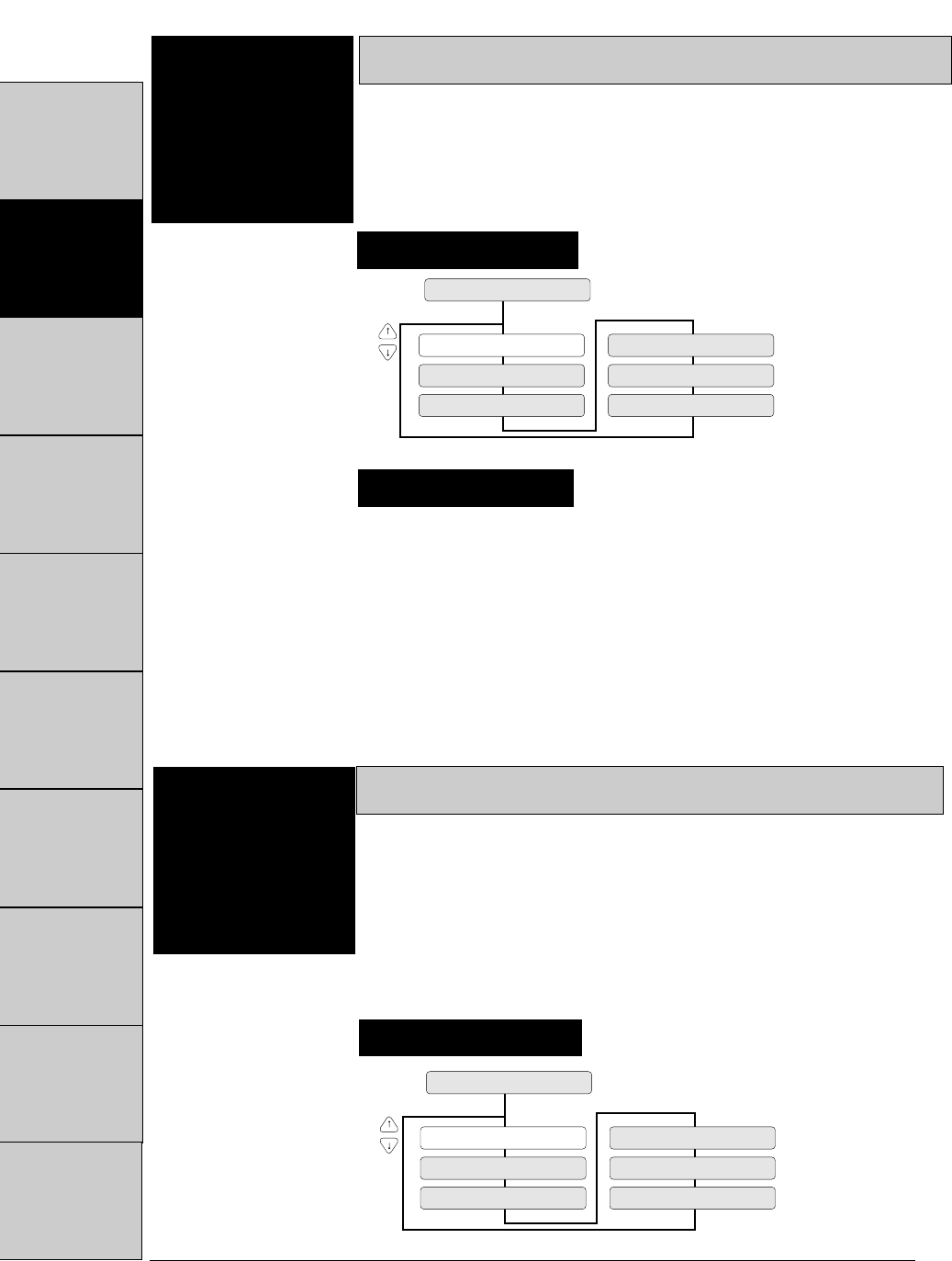
Format memory
The format memory saves six setup parameters. Optional
setup parameters can be saved in the memory and
loaded on the printer. If different formats are specified
and saved in the memory, you can change setup
parameters by using the format memory.
Saving data in format memory
3-24 — 3. Setup options —
Function
#19
19 SAVE MEMO
SAVE : MEMO 3
SAVE : MEMO 4
SAVE : MEMO 5
SAVE : MEMO 6
SAVE : MEMO 1
SAVE : MEMO 2
This function writes the data of the format memory
currently in use to the specified memo.
Supplementary notes
Setting procedures
Loading data from format memory
Function
#20
LOAD : MEMO 1
20 LOAD MEMO
LOAD : MEMO 2
LOAD : MEMO 3
LOAD : MEMO 4
LOAD : MEMO 5
LOAD : MEMO 6
This function reads data from the specified format
memory into the format memory currently in use.
The user can exchange data in the format memory with data in any of
the following memos: memo 1 to memo 6.
Setting procedures
#1 ~ #9 #10 ~ #20 #20 ~ #29 #30 ~ #38 #40 ~ #44 #50, #51 #60 ~ #67 #70 ~ #79 #80 ~ #84 #90 ~ #95
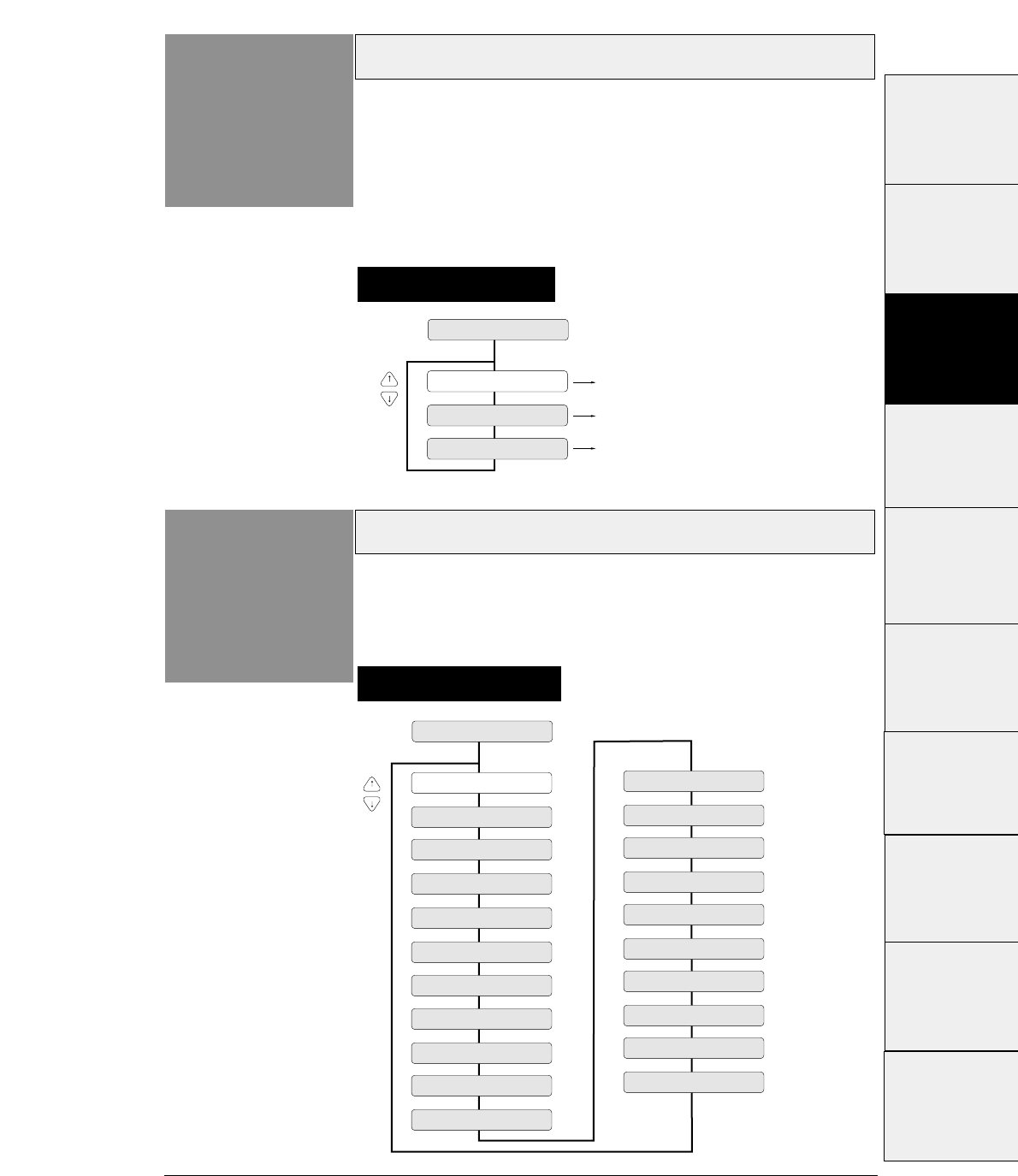
3-25
— 3. Setup options —
Emulation
Function
#20
Setting procedures
The printer has three types of emulations shown below.
Emulation compatible with the EPSON LQ-2550 TM
Emulation compatible with the IBM 2391™
Emulation compatible with the Hewlett Packard
Rugged Writer 480 TM (PCL3) TM
20 EMULATION
EML : EPSON
EML : IBM
Selecting emulation EPSON
Selecting emulation IBM
EML : HP Selecting emulation HP
Character table (HP)
Function
#21 Setting procedures
This function specifies the character table used in the
HP mode.
21 CHR TB HP
TBL : ROMAN-8
TBL : CODE PG
TBL : PC-8D/N
TBL : LEGAL
TBL : SWEDEN 1
TBL : SWEDEN 2
TBL : FRANC 1
TBL : GERMN 1
TBL : U. K.
TBL : PORTU 1
TBL : NORWAY 1
TBL : NORWAY 2
TBL : ITALY
TBL : FRANC 2
TBL : GERMN 2
TBL : SPAIN 2
TBL : SPAIN 3
TBL : JAPAN
TBL : PORTU 2
TBL : IRV
TBL : SPAIN 1
#1 ~ #9
#10 ~ #20
#20 ~ #29
#30 ~ #38
#40 ~ #44
#50, #51
#70 ~ #79
#80 ~ #84
#90 ~ #95 #60 ~ #67
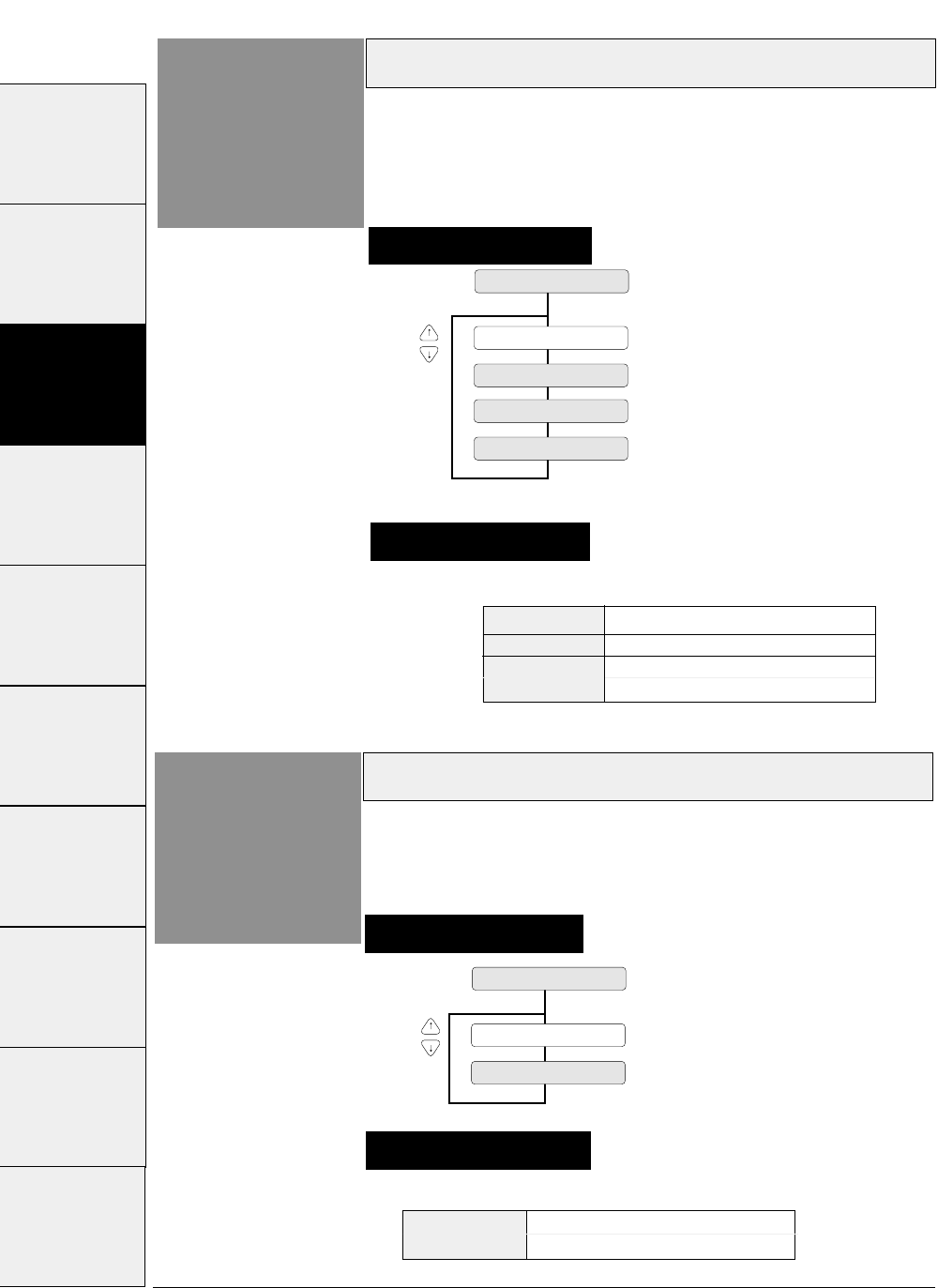
SET1 Character set 1
SET2 Character set 2
Character table (IBM)
3-26 — 3. Setup options —
Function
#23
23 CHR TB IBM
TBL: SET 1
TBL: SET 2
This function specifies the character table used in the
IBM mode.
Supplementary notes
Setting procedures
The values specified here serve as the default values.
Supplementary notes
Character table (EPSON)
Function
#22 Setting procedures
This function specifies the character table used in the
EPSON mode.
22 CHR TB EPSON
TBL : ITALIC
TBL : GRAPHIC
TBL : DOWN LD
TBL : CODE PG
ITALIC Italic table
GRAPHIC Extended graphic table
DOWN LD Download table
CODE PG Code page
#1 ~ #9 #10 ~ #20 #20 ~ #29 #30 ~ #38 #40 ~ #44 #50, #51 #60 ~ #67 #70 ~ #79 #80 ~ #84 #90 ~ #95
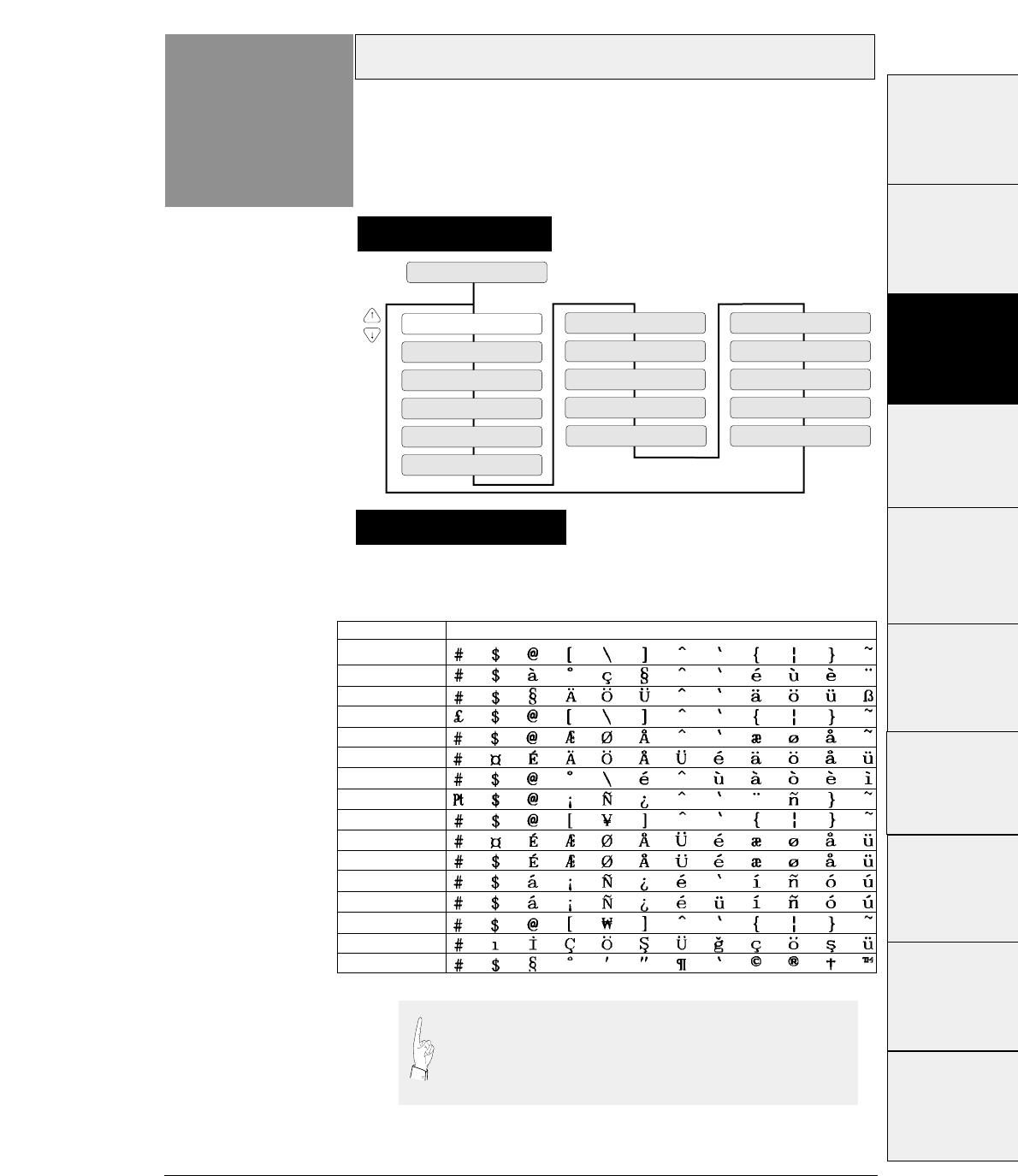
3-27
— 3. Setup options —
These national fonts are not applicable to the IBM or HP mode.
The following table shows the national fonts.
National font (EPSON)
Function
#24
24 NATIONAL FONT
CNTRY: USA
CNTRY: FRANCE
CNTRY: GERMANY
CNTRY: U.K.
CNTRY: DENMRK
CNTRY: SWEDEN
CNTRY: ITALY
CNTRY: SPAIN
CNTRY: JAPAN
CNTRY: NORWAY
CNTRY: DNMRK 2
CNTRY: SPAIN 2
CNTRY: LATN AM
CNTRY: KOREA
CNTRY: TURKEY
CNTRY: LEGAL
Supplementary notes
Setting procedures
The printer has sixteen national fonts as shown below:
U.S.A., France, Germany, U.K., Denmark, Sweden, Italy, Spain, Japan,
Norway, Denmark 2, Spain 2, Latin America, Korea, Turkey, and Legal
23 24 40 5B 5C 5D 5E 60 7B 7C 7D 7E
U.S.A.
France
Germany
U.K.
Denmark
Sweden
Italy
Spain
Japan
Norway
Denmark
2
Spain
2
Latin America
Korea
Turkey
Legal
If some specific characters are printed in a font of another
nation, the code page or national font may be specified
improperly. Refer to the manual of the computer or
application software used. Use great care with software
produced in other countries.
#1 ~ #9
#10 ~ #20
#20 ~ #29
#30 ~ #38
#40 ~ #44
#50, #51
#70 ~ #79
#80 ~ #84
#90 ~ #95 #60 ~ #67
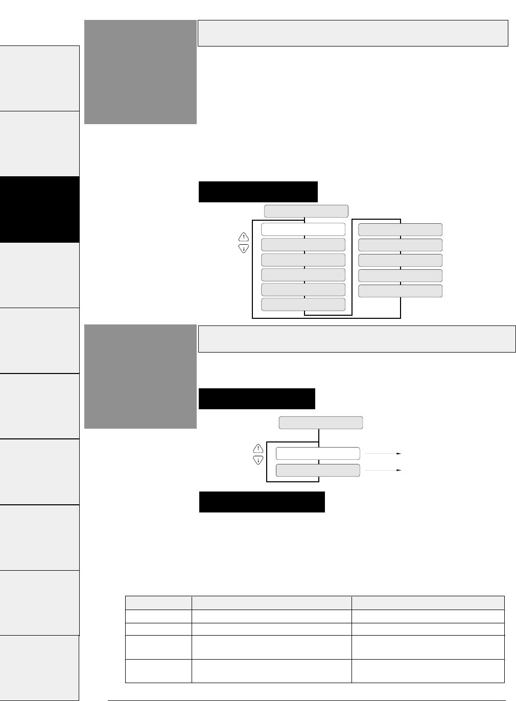
Code page
3-28 — 3. Setup options —
Function
#25
C.P.: 437
C.P.: 850
C.P.: 857
C.P.: 858
C.P.: 860
25 CODE PAGE
C.P.: 863
C.P.: 861
C.P.: 865
C.P.: BRASCII
C.P.: ABICOMP
C.T.: ISO-1
The printer has eleven code pages shown below:
(1) Code page 437: U.S.A.
(2) Code page 850: Multilingual
(3) Code page 857: Turkey
(4) Code page 858: Multilingual (EURO symbol)
(5) Code page 860: Portugal
(6) Code page 861: Icelandic
(7) Code page 863: Canadian-French
(8) Code page 865: Norway
(9) Code page Brascii
(10) Code page Abicomp
(11) ISO-1: Western Europe, ISO-8859-1
Alternate graphics mode (AGM) (IBM)
Function
#26
AGM : NO
AGM : YES
26 AGM IBM
AGM is invalid.
AGM is valid.
This function enables the alternate graphics mode
(AGM) commands to be used.
Setting procedures
Setting procedures
This function enables the IBM mode to use the high-density
graphic printing function originally available in the EPSON
mode.
When the AGM function is valid, the software command
available in the EPSON mode can be used even in the IBM
mode.
Supplementary notes
Command AGM invalid (NO) AGM valid (YES)
ESC 3 n
Specifying n/216" line feed pitch Specifying n/180" line feed pitch
ESC J n
Executing n/216" line feed pitch Executing n/180" line feed pitch
ESC A n
Registering n/72" line feed pitch that Specifying n/60" line feed pitch
is specified with ESC 2.
ESC
✻
m
Unusable Various graphic modes can be
n1 n2
executed.
#1 ~ #9 #10 ~ #20 #20 ~ #29 #30 ~ #38 #40 ~ #44 #50, #51 #60 ~ #67 #70 ~ #79 #80 ~ #84 #90 ~ #95
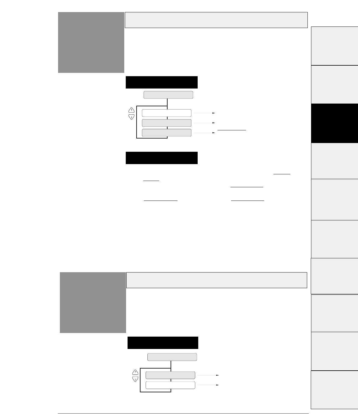
3-29
— 3. Setup options —
1. EPSON mode
If AUTOFEED is selected, the printer checks the AUTO
FEED signal during initialization. It executes a carriage
return with a line feed when the AUTO FEED signal is low.
It executes a carriage return with out a line feed when the
AUTO FEED signal is high. The AUTO FEED signal is
usable only when the PARALLEL interface or AUTO is
selected. A carriage return without a line feed is executed
when the SERIAL interface is selected.
2. IBM or HP mode
If AUTOFEED is selected, a carriage return without a line
feed is executed.
CR code function
Function
#27
CR : CR ONLY
CR : CR + LF
27 CR SETTING
Carriage return without a line feed
CR : AUTOFEED AUTO FEED signal enabled
Carriage return with a line feed
Supplementary notes
Setting procedures
This function specifies whether or not to feed a line
when the printer receives a carriage return (CR)
command.
LF code function
Function
#28
LF : LF ONLY
LF : LF + CR
28 LF SETTING
Line feed without a carriage return
Line feed with a carriage return
Setting procedures
This function specifies whether or not to execute a
carriage return when the printer receives a line feed
(LF) command.
#1~#9
#10 ~ #20
#20 ~ #29
#30 ~ #38
#40 ~ #44
#50, #51
#70 ~ #79
#80 ~ #84
#90 ~ #95 #60 ~ #67
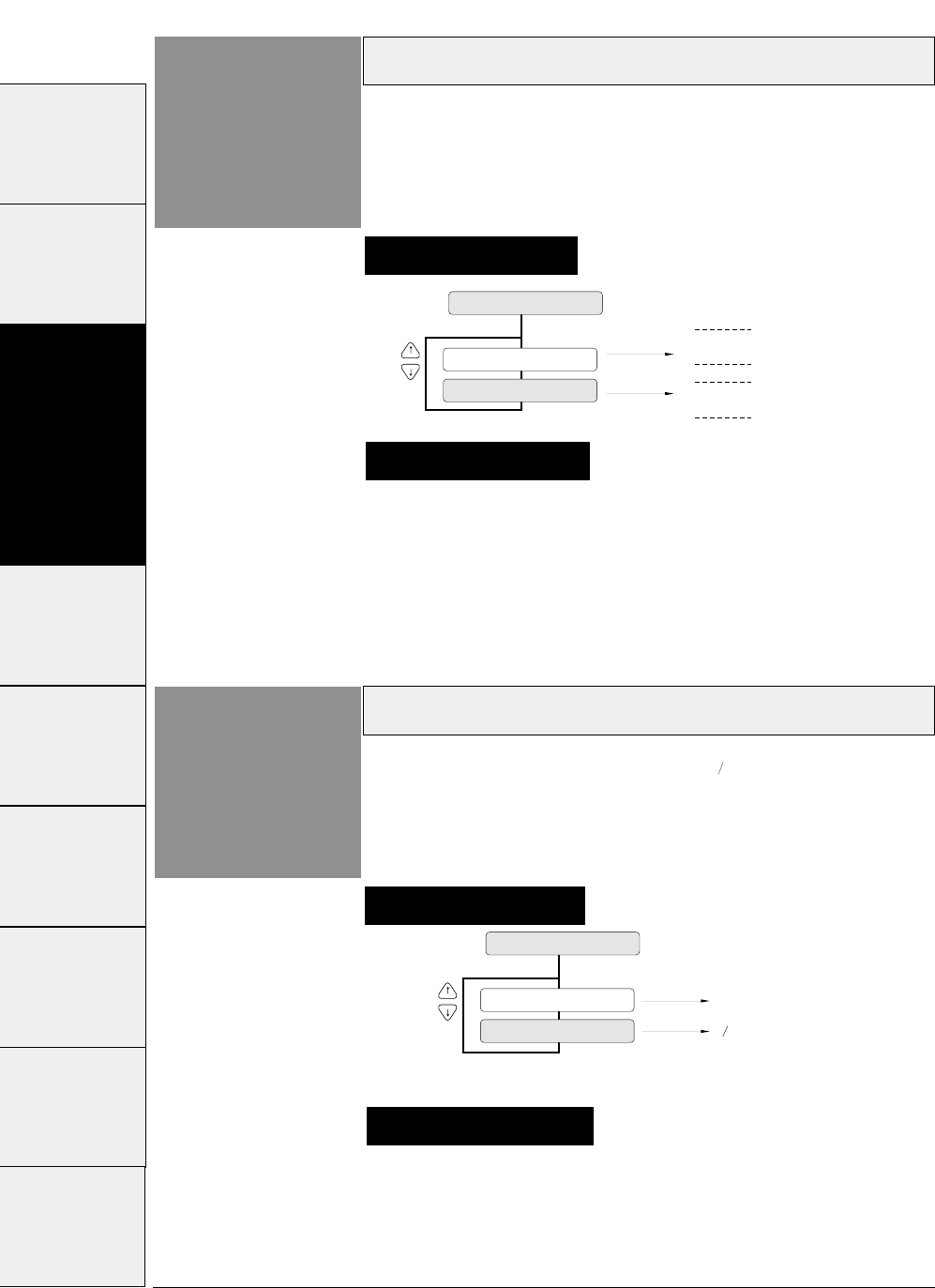
When SIMPLE is selected, the accent character of the
resident font is printed. When COMPO. is selected, the
accent symbol and the character are printed separately to
add the accent symbol in the proper position.
Accent character
3-30 — 3. Setup options —
Function
#29
29 ACCENT CHR.
PRINT: SIMPLE A
A
(Printing Example)
PRINT: COMPO.
~
~
This function specifies the method of printing accent
characters.
Supplementary notes
Setting procedures
Zero font style
Function
#30
ZERO: NO-SLSH
30 ZERO STYLE
0
0
ZERO: SLASHED
Two types of zeros are available: 0 with a slash, and 0
with no slash. This function allows the user to select
either font.
Setting procedures
The use of the slashed zero font helps to distinguish zero (0)
from the capital alphabetic letter "O".
Supplementary notes
#1 ~ #9 #10 ~ #20 #20 ~ #29 #30 ~ #38 #40 ~ #44 #50, #51 #60 ~ #67 #70 ~ #79 #80 ~ #84 #90 ~ #95
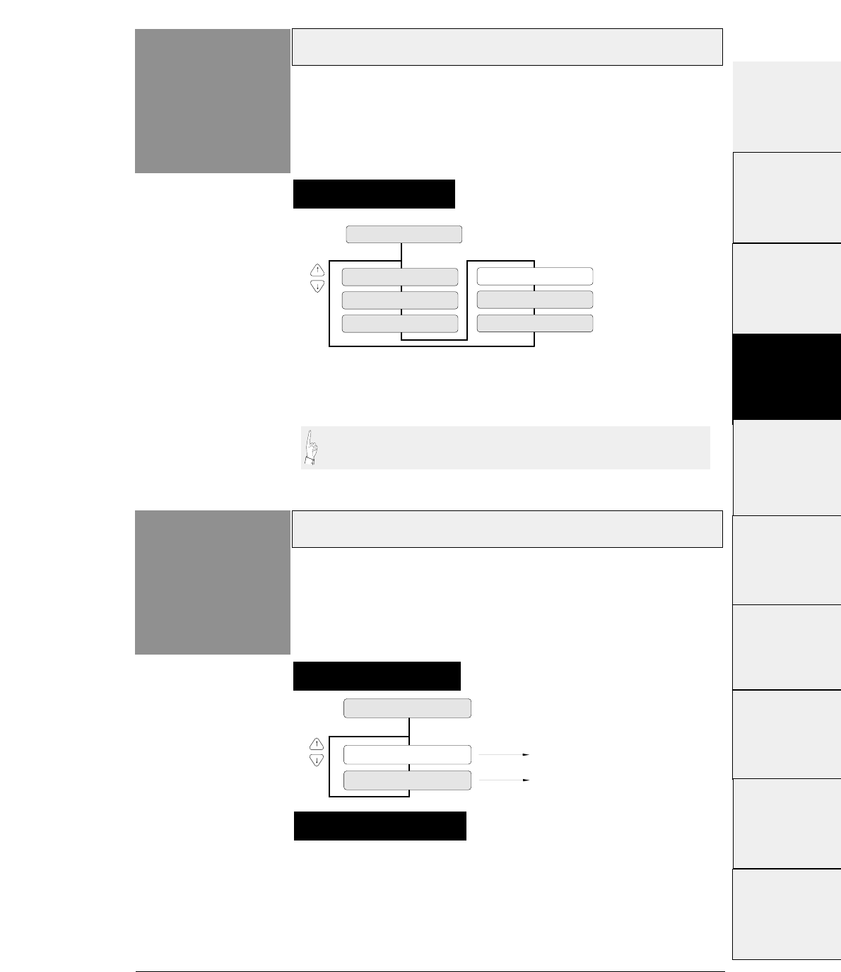
3-31
— 3. Setup options —
Horizontal tab
Function
#31
31 TABULATION
TAB: 2 CHAR
TAB: 4 CHAR
TAB: 6 CHAR
TAB: 8 CHAR
TAB: 10 CHAR
TAB: 12 CHAR
The actual position of the horizontal tab depends on the
processing of the selected emulation.
Setting procedures
Output data can be printed within the printable area of the form by
adjusting the tab when outputting nested program lists.
Locking page length
Function
#32
Software command is invalid.
32 PAGE LOCK
Software command is valid.
LOCK: NO
LOCK: YES
This function specifies whether or not to change the
page length specified in the SETUP MODE by a
software command.
Supplementary notes
Setting procedures
The right and left margins can be changed by software
commands regardless of this function. This function can also
specify whether or not to change the top and bottom margins
by a software commands.
#1 ~ #9
#10 ~ #20
#20 ~ #29
#30 ~ #38
#40 ~ #44
#50, #51
#70 ~ #79
#80 ~ #84
#90 ~ #95 #60 ~ #67
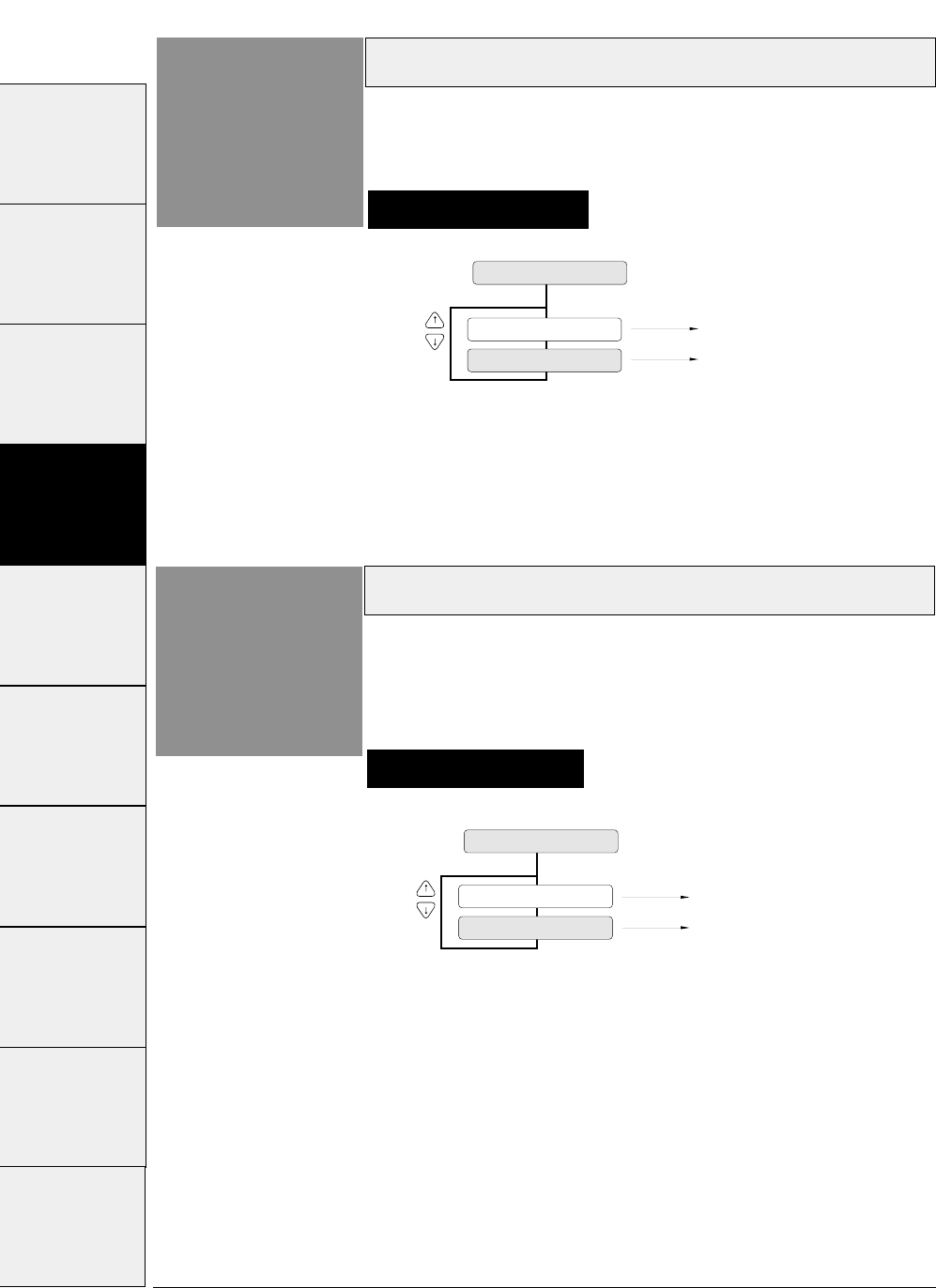
33 FONT LOCK
LOCK: NO
Software command is invalid.
Software command is valid.
LOCK: YES
3-32 — 3. Setup options —
Setting procedures
Locking font
Function
#33 This function specifies whether or not to change the
typeface of font selected in the SETUP MODE by a
software command.
Setting procedures
Locking character pitch
Function
#34 This function specifies whether or not to change the
character pitch selected in the SETUP MODE by a
software command.
34 PITCH LOCK
LOCK: YES Software command is invalid.
Software command is valid.
LOCK: NO
#1 ~ #9 #10 ~ #20 #20 ~ #29 #30 ~ #38 #40 ~ #44 #50, #51 #60 ~ #67 #70 ~ #79 #80 ~ #84 #90 ~ #95
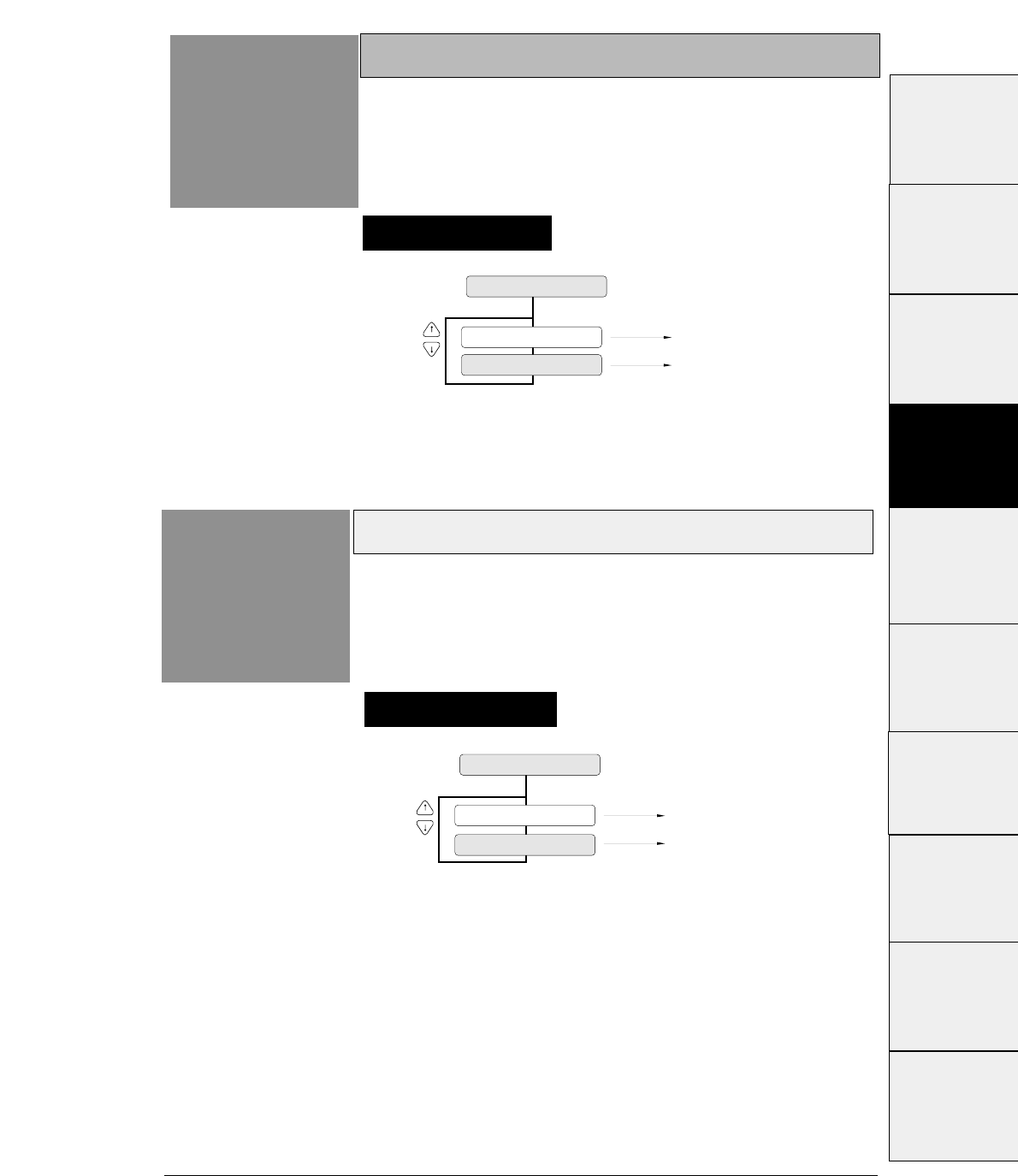
3-33
— 3. Setup options —
Setting procedures
Locking character quality
Function
#35 This function specifies whether or not to change the
character quality selected in the SETUP MODE by a
software command.
35 QLTY LOCK
Software command is invalid.
Software command is valid.
LOCK: YES
LOCK: NO
Setting procedures
Locking character table
Function
#36 This function specifies whether or not to change the
character table selected in the SETUP MODE by a
software command.
36 CHR TBL LOCK
LOCK: YES
LOCK: NO
Software command is invalid.
Software command is valid.
#1 ~ #9
#10 ~ #20
#20 ~ #29
#30 ~ #38
#40 ~ #44
#50, #51
#70 ~ #79
#80 ~ #84
#90 ~ #95 #60 ~ #67
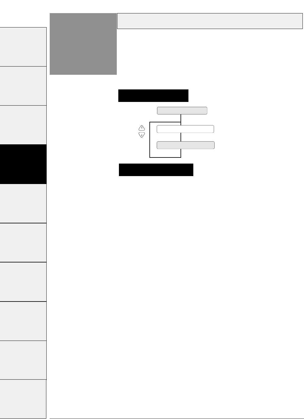
3-34 — 3. Setup options —
Setting procedures
FF code set at TOF position
Function
#37 This function specifies whether or not FF (Form Feed)
is executed at TOF.
When “YES
” is set, the FF code performs Form Feed even if
the present position is at TOF.
When “NO” is set, the FF code is ignored when the present
position is at TOF.
37 FF CODE/TOF
FF CODE/TOF : NO
FF CODE/TOF : YES
Certain kinds of software send commands to feed a
blank page without printing. Select "FF CODE/TOF
:NO" to neglect this command.
Supplementary notes
#1 ~ #9 #10 ~ #20 #20 ~ #29 #30 ~ #38 #40 ~ #44 #50, #51 #60 ~ #67 #70 ~ #79 #80 ~ #84 #90 ~ #95
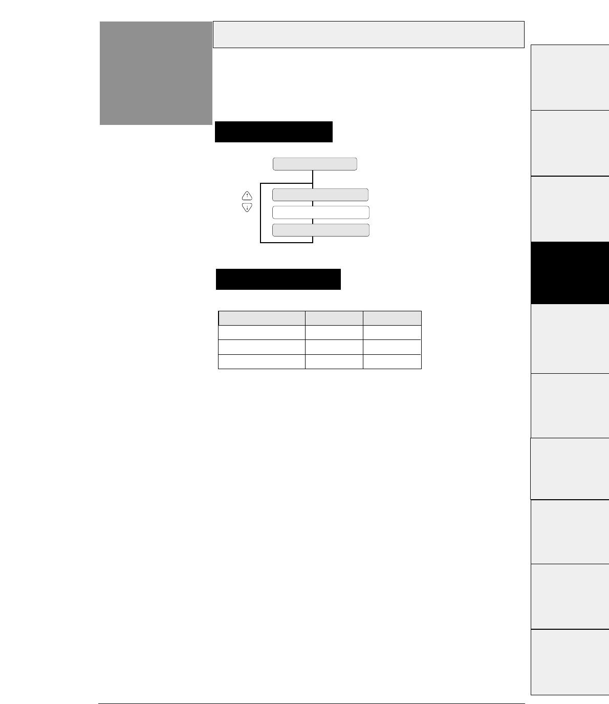
3-35
— 3. Setup options —
Setting procedures
Setting the graphic printing speed
Function
#38 120DPI, 180DPI, 240DPI and 360 DPI graphic
printing speeds are set.
38 GR QLTY
QLTY : MODE2
QLTY : MODE3
QLTY : MODE1
The graphic printing speed setting selects the character
quality in the panel setting and is effective only when
"Quality : NORMAL LQ" is selected.
Supplementary notes
Graphic MODE
MODE 1
MODE 2
MODE 3
Printing speed
Slow
Normal
Fast
Quality
Fine
Normal
Coarse
#1 ~ #9
#10 ~ #20
#20 ~ #29
#30 ~ #38
#40 ~ #44
#50, #51
#70 ~ #79
#80 ~ #84
#90 ~ #95 #60 ~ #67
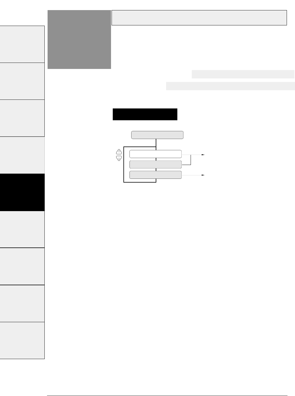
3-36 — 3. Setup options —
Setting procedures
Validity of bar code and enlarged character
Function
#40
40 BC / L.CHR
BC: IGNORED Bar code and enlarged character are invalid.
Bar code and enlarged character are valid.
BC: MODE 1
BC: MODE 2
This function specifies whether or not to activate the
bar code and enlarged character function. If MODE 1
or MODE 2 is selected, the bar code and enlarged
character can be printed.
If MODE 1 is selected, ESC SI or ESC SO cannot be used for
the bar code data start or stop command.
If MODE 2 is selected, ESC SI or ESC SO can be used for the
bar code data start or stop command.
See page 5-1 for details of the bar code.
See page 5-16 for details of the enlarged character.
#1 ~ #9 #10 ~ #20 #20 ~ #29 #30 ~ #38 #40 ~ #44 #50, #51 #60 ~ #67 #70 ~ #79 #80 ~ #84
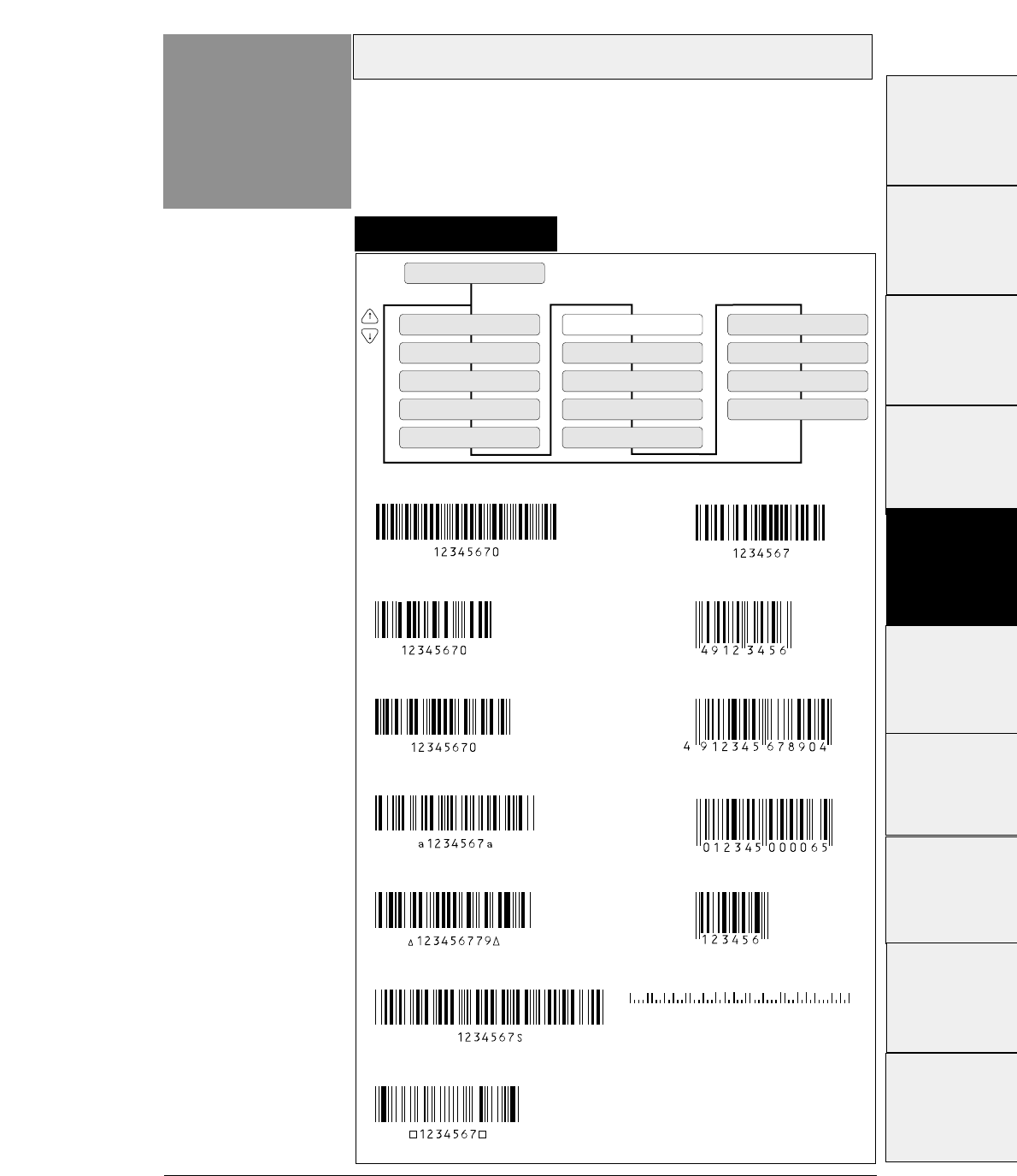
3-37
— 3. Setup options —
Bar code type
Function
#41
41 BC TYPE
TYPE: INDST25
TYPE: INTRL25
TYPE: MATRIX
TYPE: CODABAR
TYPE: CODE11
TYPE: CODE39
TYPE: CODE93
TYPE: CODE128
TYPE: EAN-8
TYPE: EAN-13
TYPE: UPC-A
TYPE: UPC-E
TYPE: POSTNET
TYPE: ELEMENT
Industrial 2 of 5
Interleaved 2 of 5
Matrix 2 of 5
CODABAR
CODE 11
CODE 39
CODE 93
**
CODE 128
EAN-8
EAN-13
POSTNET
UPC-E
UPC-A
This function specifies one of thirteen available types
of bar code.
The bar code type specified here is regarded as the default setting,
which can be changed by a software command.
Setting procedures
#1~#9
#10 ~ #20
#20 ~ #29
#30 ~ #38
#40 ~ #44
#50, #51
#70 ~ #79
#80 ~ #84
#90 ~ #95 #60 ~ #67
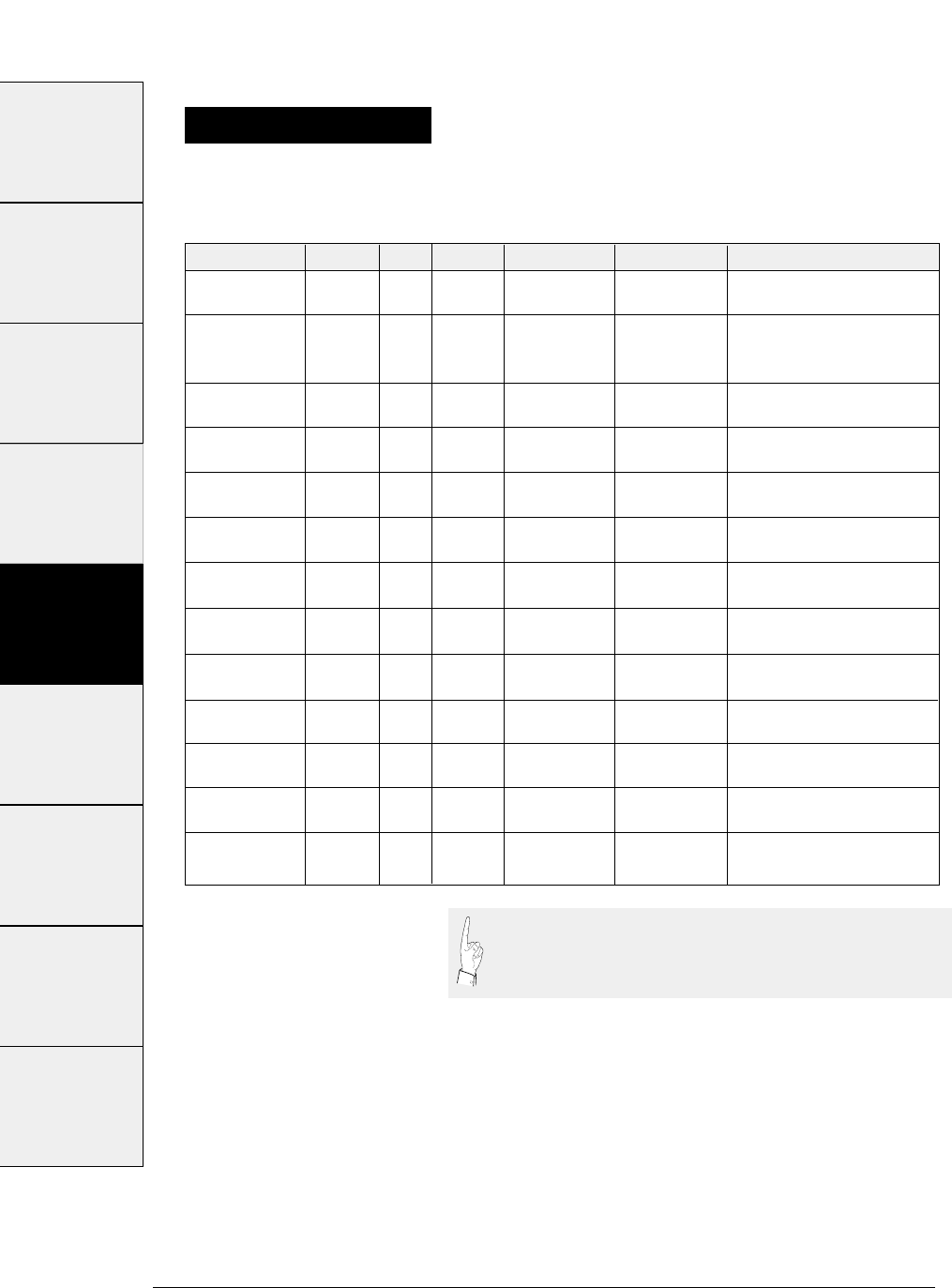
Bar code Structure ICG letters (#) Check character Sample data Remark
Industrial 2/5 5B4S Yes 0-9 Yes 1234567
(Mod 10)
Interleaved 2/5 5B5S No 0-9 Yes 1234567
(2 characters (Mod 10)
as one unit)
Codabar 4B3S Yes 0-9, Yes 1234567
(Mod 16)
Matrix 2/5 3B2S Yes 0-9 Yes 1234567
(Mod 10)
Code 11 3B2S Yes 0-9,"-" Yes 1234567
(Mod 11)
Code 39 5B4S Yes 0-9, Yes 1234567
AB,...(43) (Mod 43)
Code 93 3B3S No ASCII Yes 1234567
(128) (Mod 47)
Code 128 3B3S No ASCII Yes 1234567
(128) (Mod 103)
EAN-8 2B2S No 0-9 Yes 4912345
(Mod 10)
EAN-13 2B2S No 0-9 Yes 491234567890
(Mod 10)
UPC-A 2B2S No 0-9 Yes 01234500006
(Mod 10)
UPC-E 2B2S No 0-9 Yes 01234500006
(Mod 10)
Postnet 2LB3SB No 0-9 Yes 123456789
(Mod 10)
3-38 — 3. Setup options —
Even number, including
check character. Data
length is variable.
Start and end codes are
sent by the user.
Start and end codes are (∆)
code. Dual check character
Start and end codes are
asterisk (*) codes.
Two check characters
8 digits (2 prefix code +5
data code+Check character)
13 digits (2 prefix code +10
data code+Check character)
12 digits (NSC+10 data+
Check character)
UPC-A (12-digit) data is
automatically converted into
UPC-E (10-digit) data.
6, 10 or 12 digits
(data +Check character)
Bar code specifications
The table below shows the specifications of thirteen types of bar codes
available for the printer. Bar code printing examples are shown on the
previous page.
"B" and "S" in the "Structure" column show the number of
bars and spaces which consist of one or two characters. LB
and SB mean long bar and short bar, respectively.
Special
characters: 24
#1~#9 #10 ~ #20 #20 ~ #29 #30 ~ #38 #40 ~ #44 #50, #51 #60 ~ #67 #70 ~ #79 #80 ~ #84
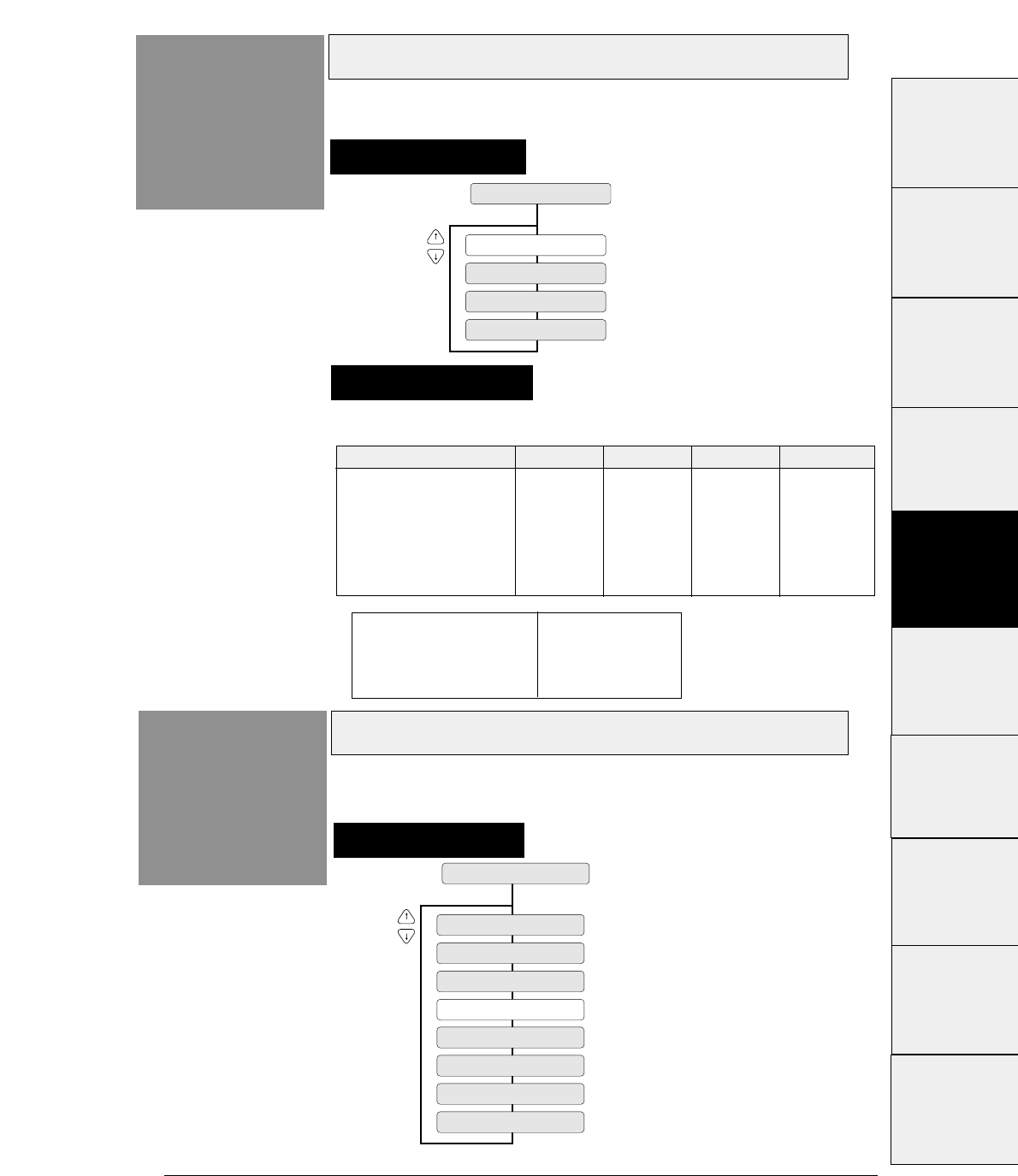
3-39
— 3. Setup options —
Bar code size
Function
#42 This function specifies the default bar code size.
Enlarged character size
Function
#43
43 LARGE CH. SIZE
SIZE : 1
SIZE : 2
SIZE : 4
SIZE : 8
SIZE : 12
SIZE : 16
SIZE : 24
SIZE : 32
This function specifies the default size of enlarged
characters.
Setting procedures
Setting procedures
42 BC SIZE
BC SIZE : 1
BC SIZE : 1.5
BC SIZE : 2
BC SIZE : 2.5
The tables below show bar code sizes and attributes.
Supplementary notes
HRI PRINT BELOW
HRI FONT OCR-B
CHECK CHARACTER Added
PRINT DENSITY 1/120 inch
SIZE 1 1.5 2 2.5
NARROW BAR 2/120inch 3/120inch 4/120inch 5/120inch
WIDE BAR 6/120inch 9/120inch 12/120inch 15/120inch
NARROW SPACE 2/120inch 3/120inch 4/120inch 5/120inch
WIDE SPACE 6/120inch 9/120inch 12/120inch 15/120inch
INTER CHARA. GAP 2/120inch 3/120inch 4/120inch 5/120inch
BAR HEIGHT 8/12inch 8/12inch 12/12inch 12/12inch
#1~#9
#10 ~ #20
#20 ~ #29
#30 ~ #38
#40 ~ #44
#50, #51
#70 ~ #79
#80 ~ #84
#90 ~ #95 #60 ~ #67
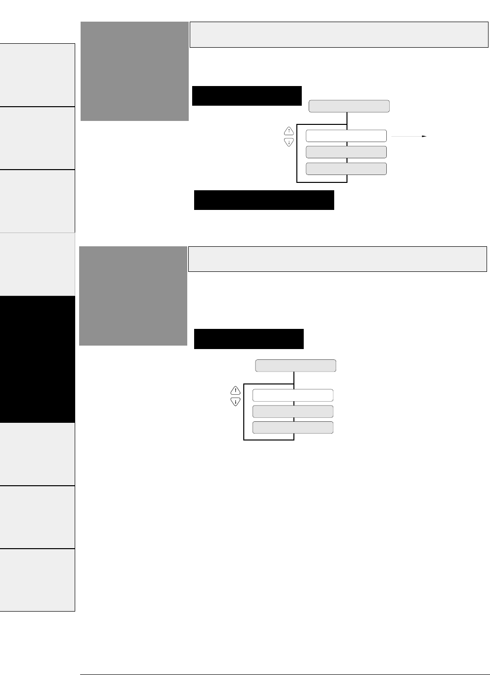
3-40 — 3. Setup options —
Software setup
Function
#44
44 SETUP COMMAND
SETUP: VALID
SETUP: IGNORED 1
Setup can be specified by
a software command.
SETUP: IGNORED 2
Setting procedures
This function specifies whether or not to accept the
software set up command.
PCL mode (HP)
Function
#50
50 PCL MODE
EML: PCL3+
EML: PCL3
EML: PCL3+D
Setting procedures
This function specifies the emulation level in the HP
mode.
PCL3:
Fully compatible with the RuggedWriter 480. The character
pitches (15,17.1 and 24) and print quality modes (HQDR,NLQ,
S.D.,S.S.D.) cannot be selected by software commands.
PCL3+:
Extra capability to the RuggedWriter 480. In this mode,
additional character pitches, print quality modes, and raster
gaphics resolutions may be selected by software command.
PCL3+D:
Limited DeskJet compatibilty. In this mode, the commands
“ESC * P # Y” and “ESC * p # X” define units in 1/360”.
If you want print DeskJet application data,you can make use of
PCL3+D. The print position and graphics of the PCL3+D are
closer than the other two modes to the DeskJet.
Supplementary notes
The setup command is ignored when "IGNORED 1" is selected.
The setup command and paper path command are ignored when
"IGNORED 2" is selected.
#1~#9 #10 ~ #20 #20 ~ #29 #30 ~ #38 #40 ~ #44 #50, #51 #60 ~ #67 #70 ~ #79 #80 ~ #84
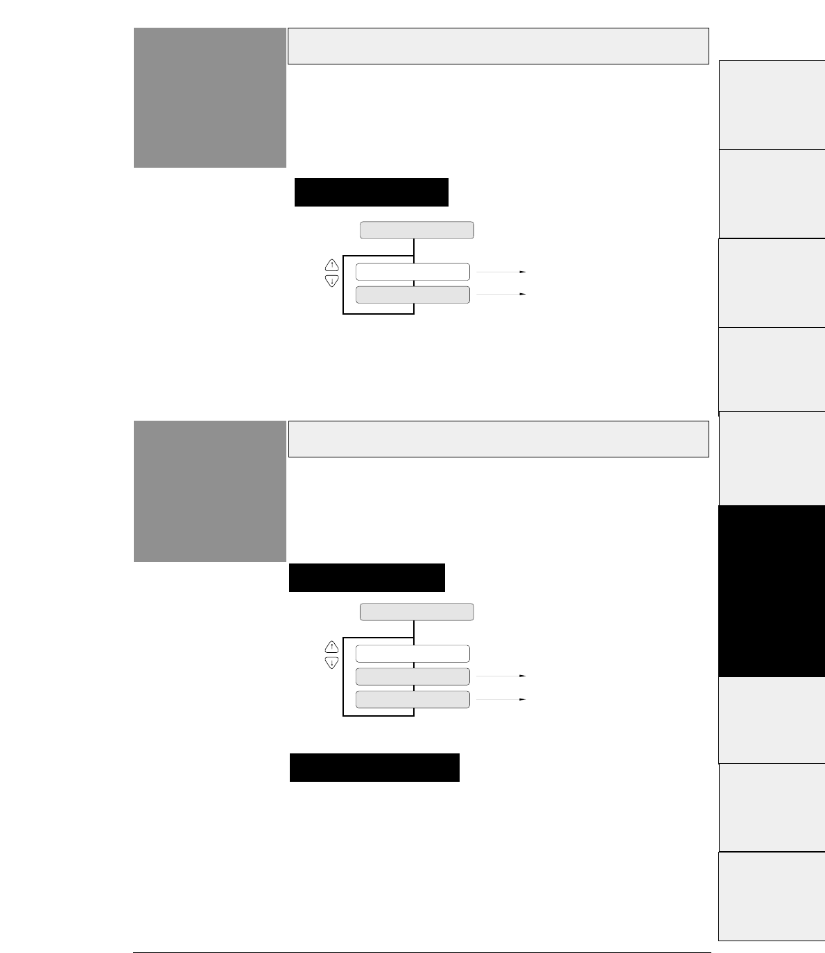
3-41
— 3. Setup options —
Secondary character table (HP)
Function
#51
51 CHR TB2 HP
TBL: LINE
MATH-7
TBL: MATH
LINE DRAW
Setting Option
Function
#60
60 OPTION
The CSF can be used.
The rear tractor can be used.
OPTION: CSF
NOT INSTALL
OPTION: REAR Tr.
This function specifies whether or not to install
option.
Setting procedures
Setting procedures
This function specifies the symbol set of the
secondary character set in the HP mode.
Supplementary notes
When the CSF (cut sheet feeder) is selected, the rear tractor
cannot be used. Similarly, when the rear tractor is selected,
the cut sheet feeder cannot be used.
#1 ~ #9
#10 ~ #20
#20 ~ #29
#30 ~ #38
#40 ~ #44
#50, #51
#70 ~ #79
#80 ~ #84
#90 ~ #95 #60 ~ #67
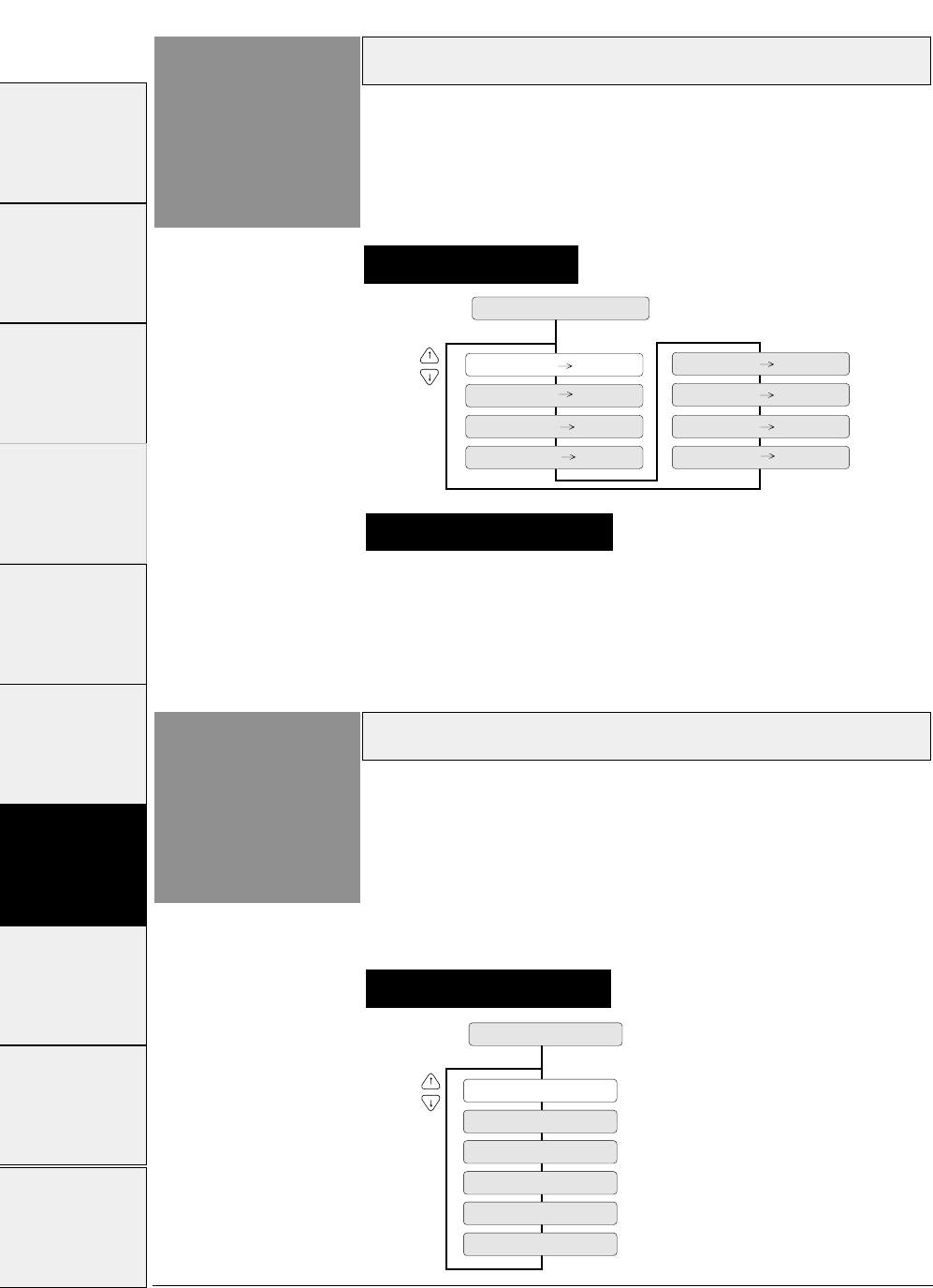
Paper path
3-42 — 3. Setup options —
Function
#61
61 PAPER PATH
PATH: F.Tr TOP
PATH: MAN FRNT
PATH: R.Tr FRNT
PATH: F.Tr REAR
PATH: MAN TOP
PATH: MAN REAR
PATH: CSF FRNT
PATH: CSF TOP
This function selects the paper path from among eight
available selections.
This option has the same function as the PAPER PATH key on the
control panel.
Automatic scrolling
Function
#62
62 AUTO SCROLL
NO SCROLL
SCROLL : 0.5 SEC
SCROLL : 1 SEC
SCROLL : 5 SEC
SCROLL : 10 SEC
SCROLL : 15 SEC
This function selects the timeout period for automatic scrolling.
When the preset timeout period has passed after data in the communication
buffer is processed, and no new data is received, the perforation of the current
page is fed to the paper cutter position, allowing printed data to be examined.
This timeout period can be set to 0.5, 1, 5, 10 or 15 seconds.
This function is valid only when printing on fanfold paper.
Setting procedures
Setting procedures
Supplementary notes
Priority is given to the most recent setting made with the PAPER
PATH key or in the EXTENDED SETUP MODE.
#1~#9 #10 ~ #20 #20 ~ #29 #30 ~ #38 #40 ~ #44 #50, #51 #60 ~ #67 #70 ~ #79 #80 ~ #84 #90 ~ #95
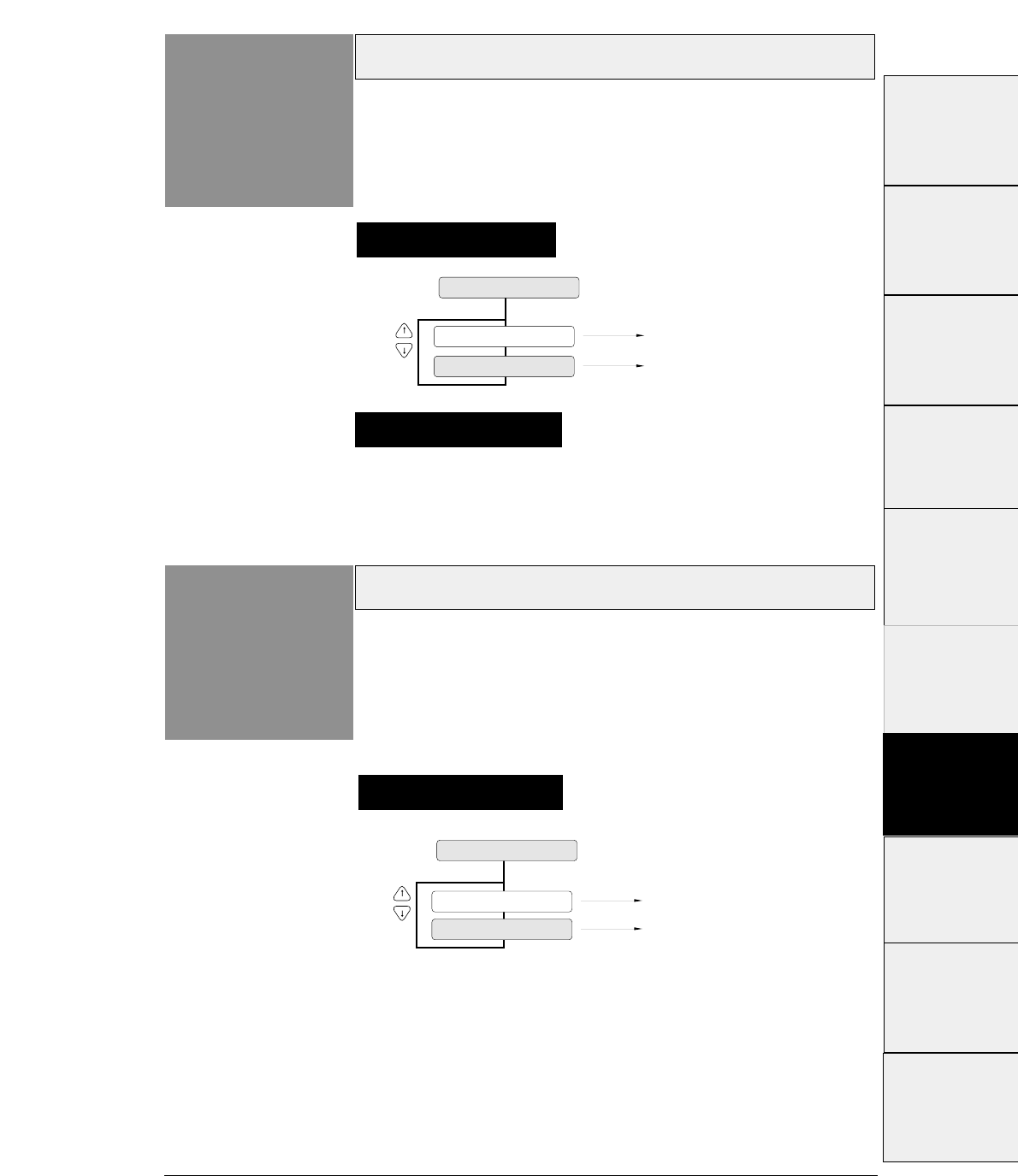
3-43
— 3. Setup options —
This function specifies whether or not to perform the
skew detection for checking whether paper has been
loaded manually on the skew.
If YES is selected, the printer ejects the paper loaded on the skew.
Out-of-paper detection
Function
#63
Skew detection
Function
#64
63 P.OUT DTCT
DETECT: NO Out-of-paper detection is
not performed.
Out-of-paper detection is
performed.
DETECT: YES
Setting procedures
Setting procedures
This function specifies whether or not to perform paper
bottom detection.
When NO is selected, printing continues for the page length that is
specified and out-of-paper is ignored even when the paper is out.
64 P.SKEW DTCT
DETECT: NO Skew detection is not performed.
Skew detection is performed.
DETECT: YES
Supplementary notes
This function should be set to NO when printing on paper
with binding holes or when using paper on which a
pattern is printed on the back.
#1~#9
#10 ~ #20
#20 ~ #29
#30 ~ #38
#40 ~ #44
#50, #51
#70 ~ #79
#80 ~ #84
#90 ~ #95 #60 ~ #67
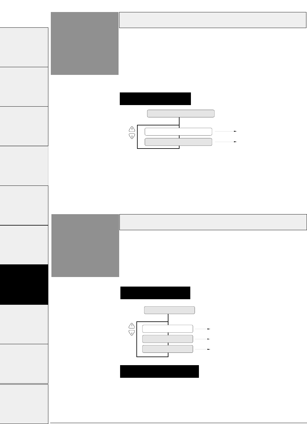
With the NORMAL line feed speed selected, the line feed
speed is reduced to half (i.e., 30 lps) when the line feed pitch
is 1/3 inch and below, or paper is loaded.
66 LF SPEED
Line feeding at normal speed (60 lps)
Line feeding at half speed (30 lps)
Line feeding at 1/3 speed (20 lps)
SPEED: NORMAL
SPEED: 1/2
SPEED: 1/3
Paper jam detection
3-44 — 3. Setup options —
Function
#65 This function specifies whether or not to perform the
paper jam detection.
If YES is selected, the printer automatically stops printing in case
of paper jamming.
Setting procedures
Paper jam detection is not
performed.
Paper jam detection is
performed.
DETECT: NO
DETECT: YES
65 P.JAM DTCT
Line feed speed
Function
#66 This function specifies the line feed speed.
The 1/2 or 1/3 line feed speed feeds paper more stably. It is useful
for thick paper, labeled sheets and multipart paper in continuous
printing.
Setting procedures
Supplementary notes
#1~#9 #10 ~ #20 #20 ~ #29 #30 ~ #38 #40 ~ #44 #50, #51 #60 ~ #67 #70 ~ #79 #80 ~ #84 #90 ~ #95
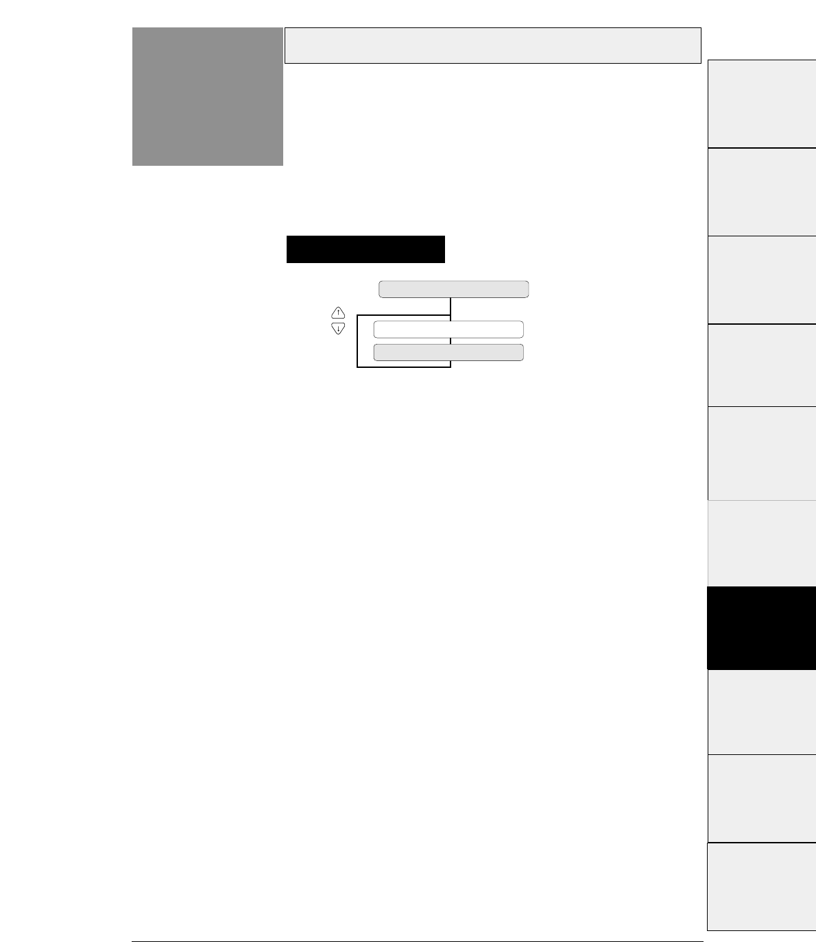
3-45
— 3. Setup options —
Setting of the auto-scrolling position
Function
#67 Set the position for executing auto-scrolling.
In the case of "TOF ONLY" : Auto-scrolling is performed
only when the present position is at TOF .
"ANY POS" : If the perforation is between the paper cutter
and printing head position, auto-scroll is performed at any
position after a prescribed time after the printing.
Setting procedures
SCROLL : TOF ONLY
SCROLL : ANY POS
67 SCROLL POS.
#1~#9
#10 ~ #20
#20 ~ #29
#30 ~ #38
#40 ~ #44
#50, #51
#70 ~ #79
#80 ~ #84
#90 ~ #95 #60 ~ #67
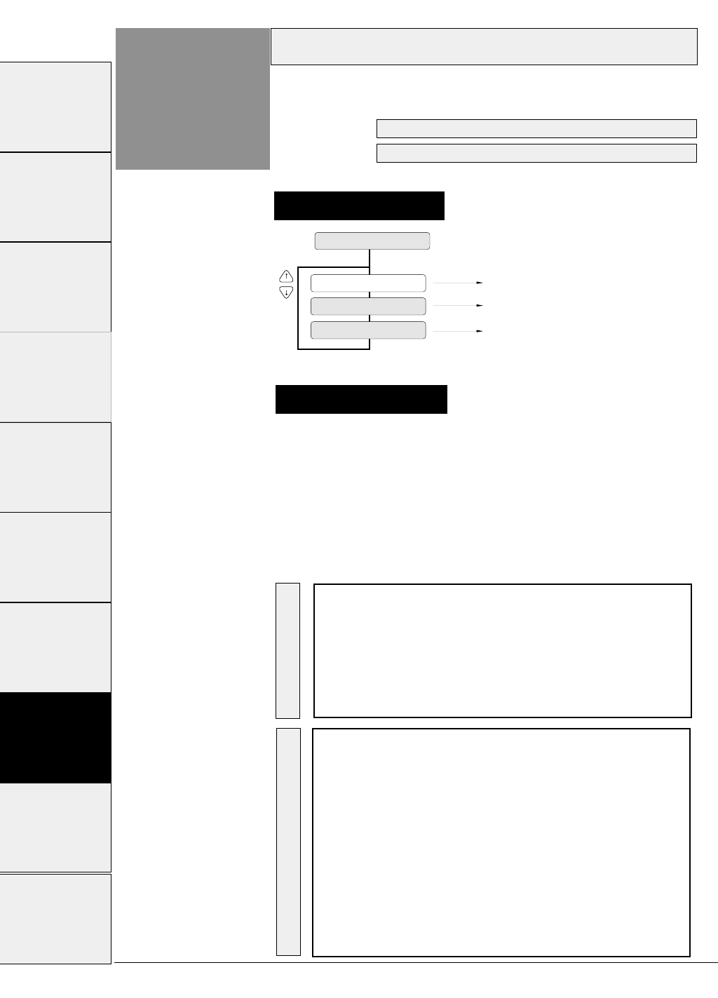
3-46
Interface
Function
#70
Setting procedures
This function selects the parallel or serial interface.
Setting procedures
70 INTERFACE
I/F: SERIAL
Parallel interface is selected.
RS-232C serial interface is selected.
Parallel and serial interfaces are switched
automatically.
I/F: PARALLEL
I/F: AUTO
See page 7-1 for details of the parallel interface.
See page 7-5 for details of the serial interface.
The functions shown below are available according to the
interface type.
The printer is set to the standard parallel and serial interface
before shipment. If it does not print data properly, recheck
the functions shown below. For the settings for the serial
interface, refer to the manual of the computer.
Supplementary notes
EXTENDED SETUP MODE Factory setting Page
#70.INTERFACE PARALLEL 3-46
#71.SELECT IN ENABLE 0 3-47
#81.BUFFER SIZE 512 KB 3-52
#82.BUSY/ACK TIMING TYPE 2 3-53
#83.DATA LATCH TIMING TYPE F. 3-53
#84.ERROR STATUS YES. 3-54
EXTENDED SETUP MODE Factory setting Page
#70.INTERFACE PARALLEL 3-46
#71.SELECT IN ENABLE 0 3-47
#72.PARITY BIT Non 3-47
#73.DATA LENGTH 8 bits 3-48
#74.STOP BIT 1 bit 3-48
#75.PROTOCOL DTR 3-49
#76.BAUD RATE 9600 bps 3-49
#77.SERIAL ERROR Print 3-50
#78.CTS ENABLE No 3-50
#79.CD ENABLE No 3-51
#80.DSR ENABLE No 3-51
#81.BUFFER SIZE 512 KB 3-52
Parallel I/F Serial I/F
— 3. Setup options —
#1~#9 #10 ~ #20 #20 ~ #29 #30 ~ #38 #40 ~ #44 #50, #51 #60 ~ #67 #70 ~ #79 #80 ~ #84 #90 ~ #95
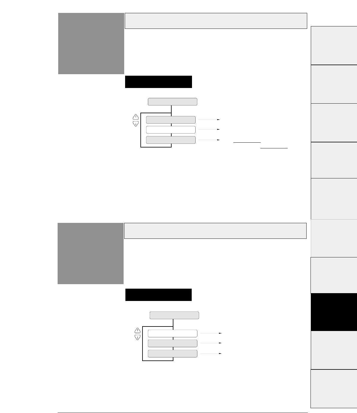
3-47
Printer select command
— 3. Setup options —
Function
#71 This function specifies whether or not to perform the
printer select command.
Setting procedures
71 SLCT IN ENBL
SLCT IN: 1
SLCT IN: 0
Printer select command is always
accepted.
SLCT IN: I/F
Printer select command is always
ignored.
Printer select command is accepted
when SELECT IN signal is set high.
It is ignored when SELECT IN
signal is set low.
Parity bit (Serial I/F)
Function
#72
Setting procedures
This function specifies the parity bit when the serial
interface is used.
72 PARITY BIT
PARITY : EVEN
Parity check is not executed.
PARITY : ODD
Even number check is executed
Odd number check is executed.
PARITY : NON
#1~#9
#10 ~ #20
#20 ~ #29
#30 ~ #38
#40 ~ #44
#50, #51
#70 ~ #79
#80 ~ #84
#90 ~ #95 #60 ~ #67
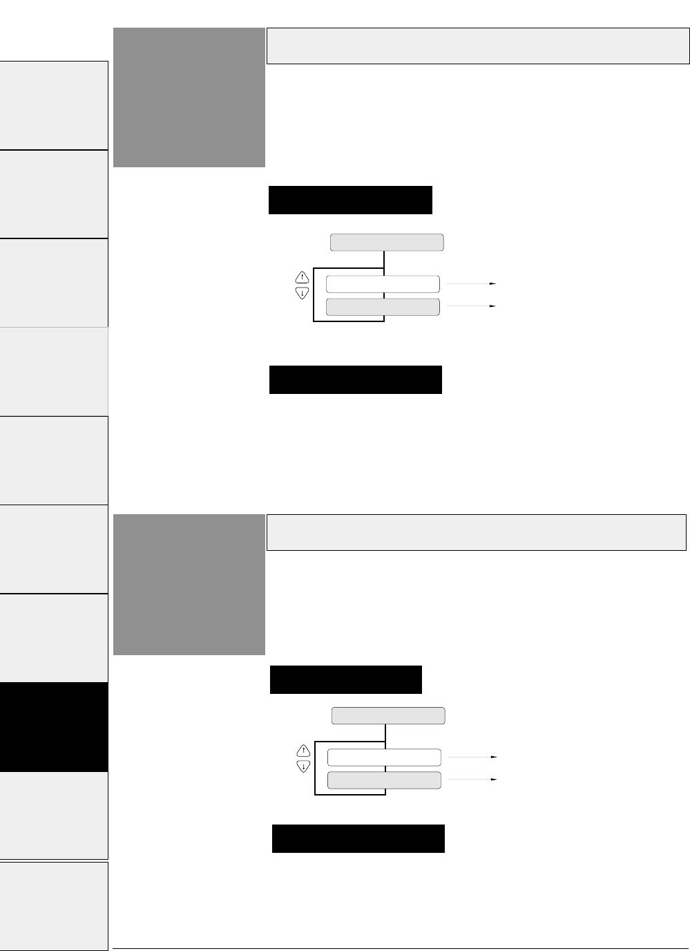
3-48 — 3. Setup options —
Data length (Serial I/F)
Function
#73
73 DATA LENGTH
LENGTH: 8 BITS
LENGTH: 7 BITS
Data length is set to 8 bits.
Data length is set to 7 bits.
Stop bit (Serial I/F)
Function
#74
Setting procedures
Setting procedures
This function specifies the data length when the serial
interface is used.
This function specifies the stop bit when the serial
interface is used
74 STOP BIT
STOP BIT: 1 BIT
STOP BIT: 2 BITS
Stop bit length is set to 1 bit.
Stop bit length is set to 2 bits.
Select the data length: 8 bits or 7 bits.
Supplementary notes
Select the stop bit length: 1 or 2 bits.
Supplementary notes
#1~#9 #10 ~ #20 #20 ~ #29 #30 ~ #38 #40 ~ #44 #50, #51 #60 ~ #67 #70 ~ #79 #80 ~ #84 #90 ~ #95
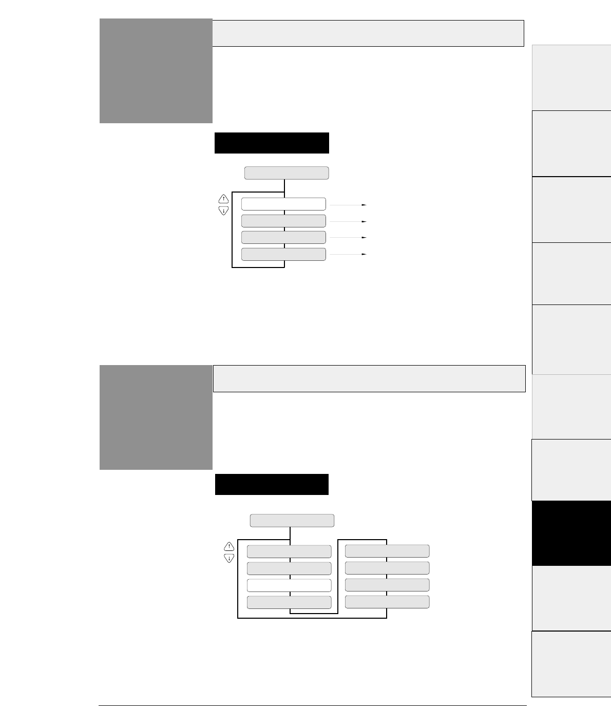
3-49
Protocol (Serial I/F)
— 3. Setup options —
Function
#75
75 PROTOCOL
PROT: DTR
PROT: XON/OF1
PROT: XON/OF2
PROT: ETX/ACK
DRT (ready/busy) protocol is selected.
X-ON/X-OFF protocol (I) is selected.
X-ON/X-OFF protocol (II) is selected.
EXT/ACK protocol is selected.
This function specifies the protocol for the serial
interface.
Baud rate (Serial I/F)
Function
#76
76 BAUD RATE
SPEED: 38400 B
SPEED: 19200 B
SPEED: 9600 B
SPEED: 2400 B
SPEED: 1200 B
SPEED: 600 B
SPEED: 4800 B SPEED: 300 B
This function specifies the data transmission rate for
the serial interface..
Setting procedures
Setting procedures
#1 ~ #9
#10 ~ #20
#20 ~ #29
#30 ~ #38
#40 ~ #44
#50, #51
#70 ~ #79
#80 ~ #84
#90 ~ #95 #60 ~ #67
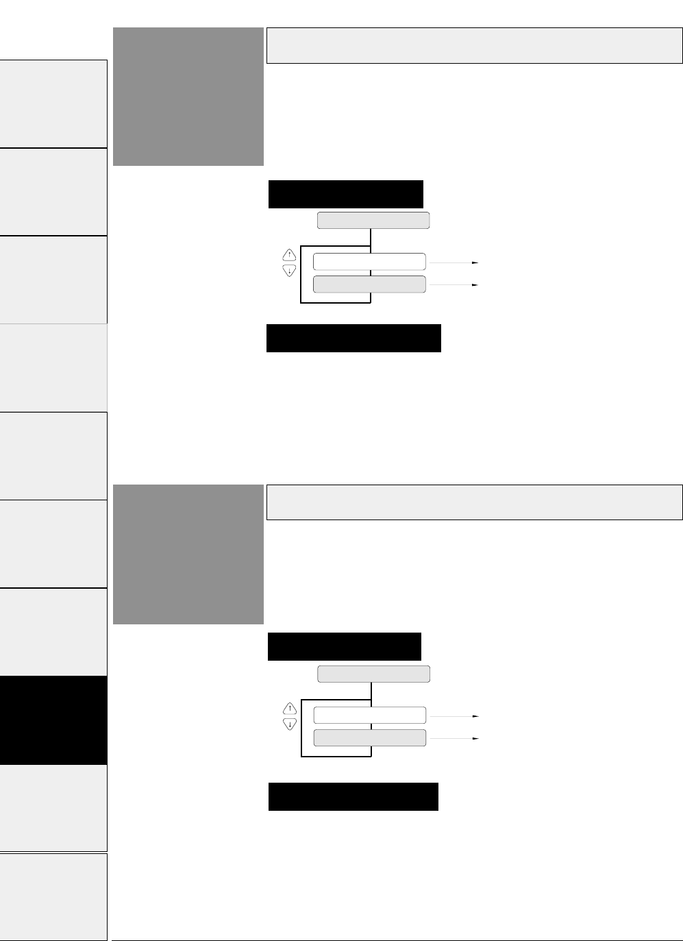
3-50 — 3. Setup options —
Serial error (Serial I/F)
Function
#77
77 SERIAL ERROR
S. ERROR: PRINT
S. ERROR: IGNORED
Asterisk (✽) is printed in case of error.
Error is ignored.
CTS signal (Serial I/F)
Function
#78
78 CTS ENABLE
CTS: NO
CTS: YES
CTS signal is ignored.
CTS signal is valid.
This function specifies whether or not to validate the
CTS (clear to send) signal.
When the X-ON/X-OFF protocol or ETX/ACK protocol is used,
the CTS signal is used to output data from the printer to the
computer.
Setting procedures
Setting procedures
This function specifies whether or not to print asterisk
‘✻’when a serial data transmission error occurs during
communication via the serial interface.
The serial data transmission error includes a parity error, framing
error and over-run error.
If a serial data transmission error occurs with the SERIAL
ERROR option selected to PRINT, the data in error is printed
as asterisk "✻". If data exceeding the buffer size is sent while
the printer is busy, the excess data is ignored. If a serial data
transfer error occurs with the SERIAL ERROR option set to
IGNORED, the erroneous data is discarded.
Supplementary notes
If this option is set to NO, the printer sends data to the
computer regardless of the CTS signal status.
If this option is set to YES, the printer checks the CTS signal
status to send data to the computer.
Supplementary notes
#1~#9 #10 ~ #20 #20 ~ #29 #30 ~ #38 #40 ~ #44 #50, #51 #60 ~ #67 #70 ~ #79 #80 ~ #84 #90 ~ #95
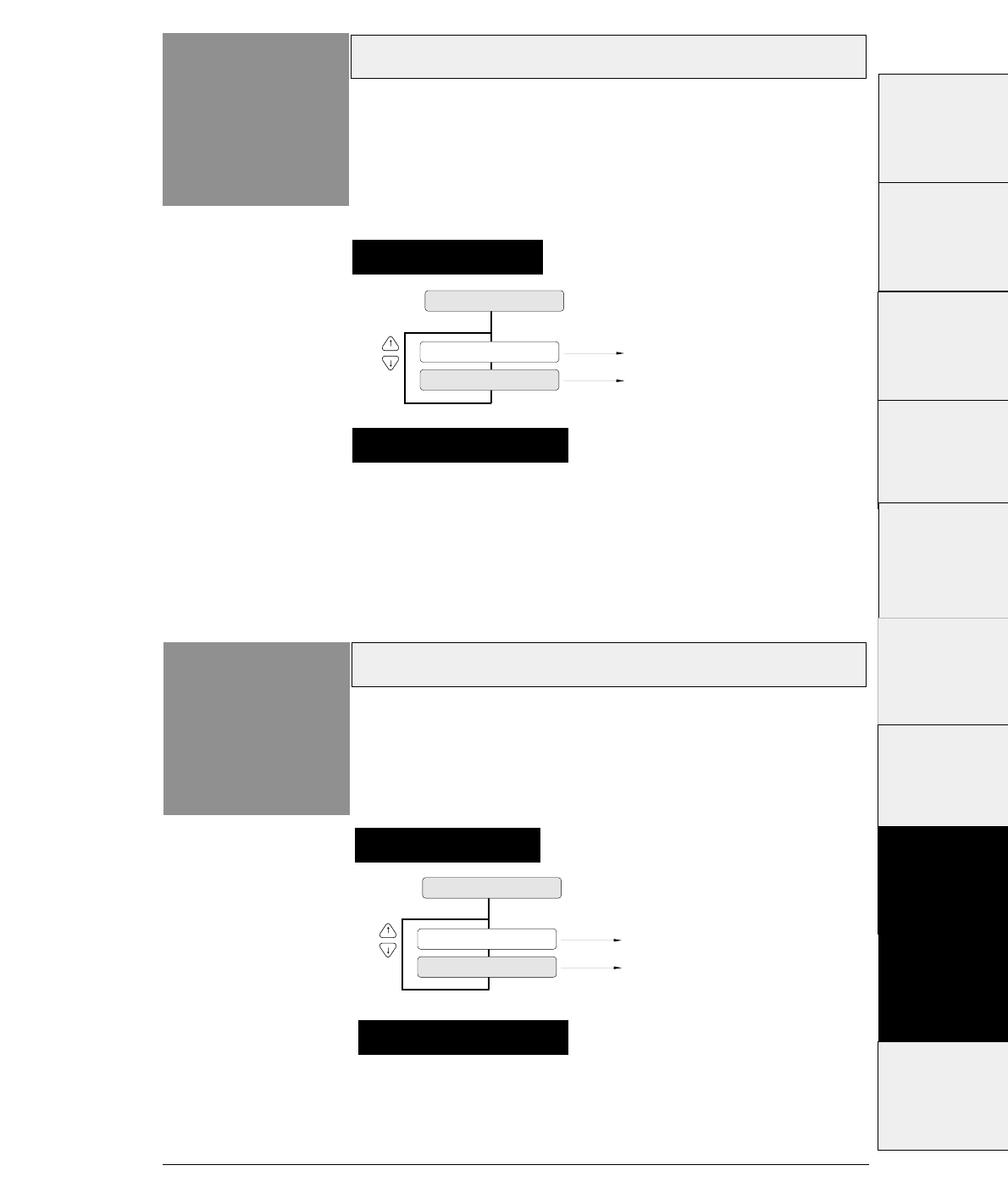
3-51
If this option is set to NO, the printer processes the received
data as valid data regardless of the CD signal status.
If this option is set to YES, the printer checks the CD signal
status to receive data from the computer.
CD signal (Serial I/F)
— 3. Setup options —
Function
#79
79 CD ENABLE
CD: NO
CD: YES
CD signal is ignored.
CD signal is valid.
This function specifies whether or not to validate the
CD (carrier detect) signal.
The CD signal indicates whether or not a modem is connected to a
communication line.
Supplementary notes
Setting procedures
DSR signal (Serial I/F)
Function
#80
Setting procedures
This function specifies whether or not to validate the
DSR(data set ready) signal.
The DSR signal indicates the status of the modem or computer.
If this option is seto to NO, the printer processes the received
data as valid data regardless of the DSR signal status.
If this option is set toYES, the printer checks the DSR signal
status to receive data from the computer.
80 DSR ENABLE
DSR: NO
DSR: YES
DSR signal is ignored.
DSR signal is valid.
Supplementary notes
#1 ~ #9
#10 ~ #20
#20 ~ #29
#30 ~ #38
#40 ~ #44
#50, #51
#70 ~ #79
#80 ~ #84
#90 ~ #95 #60 ~ #67
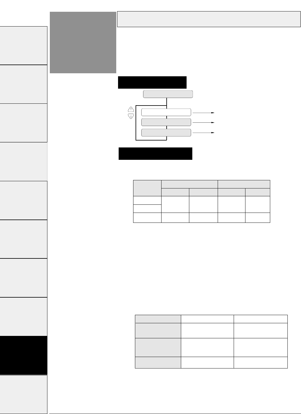
3-52 — 3. Setup options —
Setting procedures
Input buffer size
Function
#81 This function specifies the size of the input buffer. The
buffer sizes shown below are provided.
81 BUFFER SIZE
B.SIZE: 512 KB
B.SIZE: 8 KB
Buffer size of512KB selected.
Buffer size of 8KB selected.
B.SIZE: 128 B Buffer size of 128 bytes selected.
The buffer sizes shown below are provided.
CIN :
The printer enters the busy state when the
available space in the buffer is reduced below the
CIN value.
CRN :
The printer enters the ready state when the
available space in the buffer exceeds the CRN
value.
When the serial interface is used, processing differs
according to the protocol as shown below when the available
space in the buffer is inadequate.
Protocol
DTR
(Ready/Busy)
CIN processing CRN processing
X-ON/X-OFF(I)
X-ON/X-OFF(II)
ETX/ACK
BUSY READY
Sends X-OFF Sends X-ON
Stops sending ACK Begins sending ACK
Supplementary notes
BUFFER
SIZE
Parallel I/F Serial I/F
512K byte 1K byte 2K byte
CIN CRN
1K byte 2K byte
CIN CRN
8K byte
128 byte 32 byte 64 byte32byte 64 byte
When the printer enters the CIN processing in the parallel
interface, data is input at 0.5 seconds intervals.
#1~#9 #10 ~ #20 #20 ~ #29 #30 ~ #38 #40 ~ #44 #50, #51 #60 ~ #67 #70 ~ #79 #80 ~ #84 #90 ~ #95
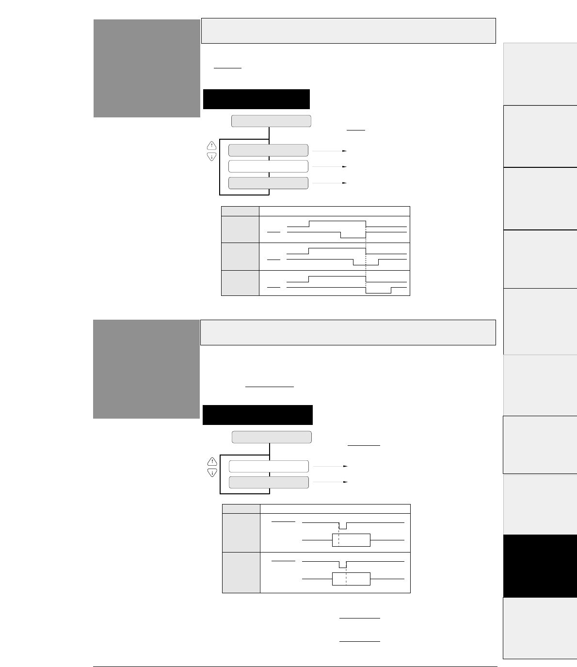
3-53
— 3. Setup options —
Setting procedures
Busy/ACK signal timing (Parallel I/F)
Function
#82 This function specifies the timing of the BUSY and
ACK signals transmitted via the parallel interface.
82 BUSY/ACK
TIMING: TYPE 1
TIMING: TYPE 2
TIMING: TYPE 3
BUSY
ACK
BUSY
ACK
BUSY
ACK
Timimg
Type
TYPE 1
TYPE 2
TYPE 3
Rising edge
Center
Falling edge
ACK signal
Data latch timing(Parallel I/F)
Function
#83
83 DATA LATCH
LTCH: TYPE F.
LTCH: TYPE R.
Timimg
Type
TYPE F.
TYPE R.
STROBE
DATA 1~8
STROBE
DATA 1~8
Falling edge
Rising edge
STROBE signal
This function specifies the timing to latch DATA 1 ~ 8
at the falling edge (TYPE F.) or rising edge (TYPE R.)
of the STROBE signal.
Setting procedures
TYPE F
.
Data is read in when the STROBE signal goes Low.
TYPE R.
Data is read in when the STROBE signal goes High.
#1 ~ #9
#10 ~ #20
#20 ~ #29
#30 ~ #38
#40 ~ #44
#50, #51
#70 ~ #79
#80 ~ #84
#90 ~ #95 #60 ~ #67
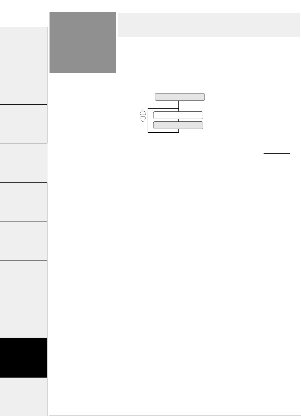
3-54 — 3. Setup options —
Function
#84
Error status signal output setting
(parallel interface)
When NO is selected, the status of the PE, ERROR,
and SELECT signals does not change even if the
printer is in out-of-paper, error, or offline state.
This function is effective when the system outputs
the printing data again when an error occurs.
This function specifies whether or not to output the
parallel interface error status signal (PE, ERROR,
SELECT) when an error occurs.
84 ERROR STATUS
ERROR STATUS: YES
ERROR STATUS: NO
#1 ~ #9 #10 ~ #20 #20 ~ #29 #30 ~ #38 #40 ~ #44 #50, #51 #60 ~ #67 #70 ~ #79 #80 ~ #84 #90 ~ #95
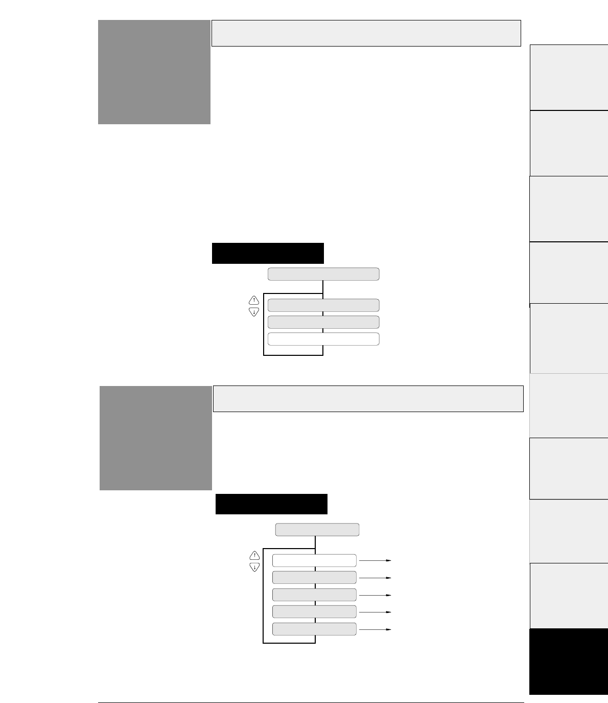
3-55
Setting procedures
— 3. Setup options —
Display language on LCD
Function
#91
91 DISPLAY LANG
LANG: ENGLISH
LANG: DEUTSCH
English
German
LANG: FRANCAIS French
LANG: ESPANOL Spanish
LANG: ITALIANO Italian
This function specifies the display language on the
LCD.
Printing direction
Function
#90 The three printing directions shown below are available.
PRE-DIRECTION: Bi-directional printing 1
Printing is done in the shortest distance through logical seeking.
When double striking, vertical double-size character printing, or
other special effect printings require several passes, they are
carried out in the same direction as the first pass.
BI-DIRECTION: Bi-directional printing 2
Logical seeking is carried out toward the closer printing start
position from the current head position to perform printing in
the shortest direction.
UNI-DIRECTION: Unidirectional printing
Printing is always done in the same direction, from the left to
right.
90 PRINT DIR
PRINT: PRE-DIR
PRINT: UNI-DIR
PRINT: BI-DIR
Setting procedures
#1~#9
#10 ~ #20
#20 ~ #29
#30 ~ #38
#40 ~ #44
#50, #51
#70 ~ #79
#80 ~ #84
#90 ~ #95 #60 ~ #67
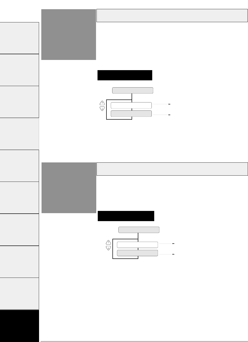
3-56 — 3. Setup options —
Setting procedures
Locking panel keys
Function
#92
92 KEY LOCK
KEY LOCK: NO
KEY LOCK: YES
Pressing a key is valid in the ONLINE
state.
Pressing a key is ignored in the ONLINE
state.
This function specifies whether or not to validate the
keys other than the RESET key (i.e., ALT + TEAR
OFF keys) and ONLINE key in the ONLINE state.
Setting procedures
Locking reset key
Function
#93
93 RESET LOCK
KEY LOCK: NO
KEY LOCK: YES
RESET key is valid in the ONLINE
state.
RESET key is ignored in ONLINE
state.
This function specifies whether or not to validate the
RESET key in the ONLINE state.
#1~#9 #10 ~ #20 #20 ~ #29 #30 ~ #38 #40 ~ #44 #50, #51 #60 ~ #67 #70 ~ #79 #80 ~ #84 #90 ~ #95
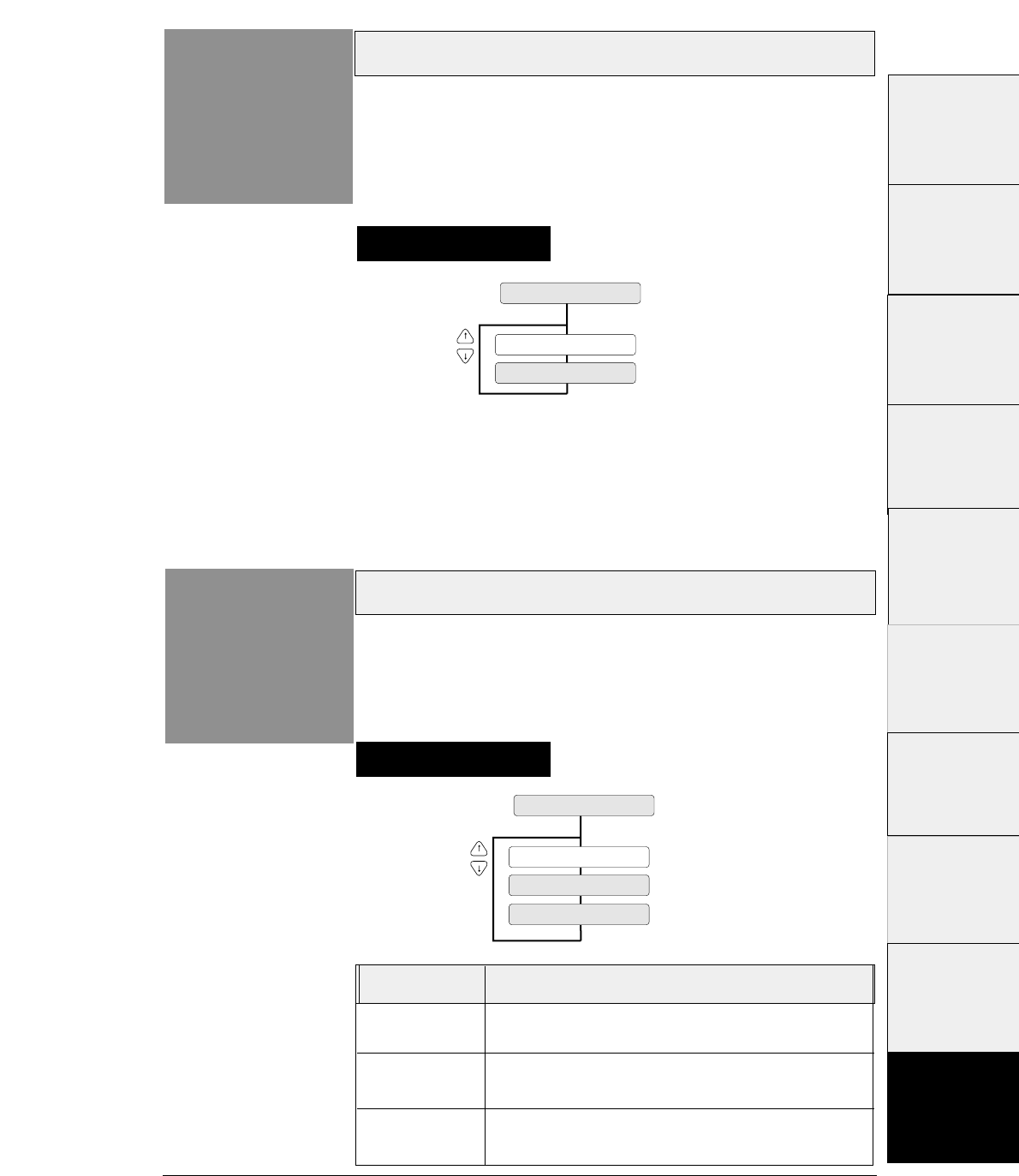
3-57
— 3. Setup options —
Setting ENERGY STAR
Function
#94
SLEEP MODE : YES
94 SLEEP MODE
SLEEP MODE : NO
This function sets the power conservation standby mode.
When this mode is valid, if the standby mode continues
about 14 minutes after printing, the power conservation
mode is engaged. The normal mode is effective when
any print action is performed.
Setting procedures
Printing setup list
Function
#95
LIST : PATH & FORM
95 SETUP LISTING
LIST : EXTEND
LIST : ALL SET
This function prints the list of the parameters specified
in the setup mode.
Setting procedures
#1 ~ #9
#10 ~ #20
#20 ~ #29
#30 ~ #38
#40 ~ #44
#50, #51
#70 ~ #79
#80 ~ #84
#90 ~ #95 #60 ~ #67
Display Print
PATH&FORM
Selectable paper
paths and six format memories.
EXTEND Parameters specified on the EXTENDED SETUP
MODE are printed.
ALL SET All parameters specified in the setup modes and data in
the six memories are printed.
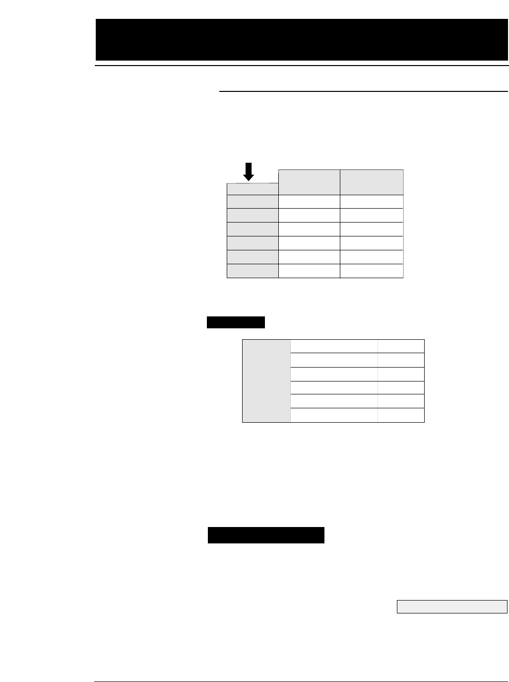
The printer has both standard and high-speed print modes.
The following table shows the print modes.
When NLQ, HQDR, DRAFT, S. D. or S.S.D. is
selected, the graphic is printed at high speed with
lower bit density.
Select a quality with the QUALITY key or with #10
QUALITY in the SETUP MODE.
4-1
— 4. Functions —
4. Functions
High-speed printing
SET UP
LQ
NLQ
HQDR
DRAFT
S.D.
S.S.D.
ESC x 1
LQ is selected.
Selected with the QUALITY key or with #10 QUALITY in the SETUP MODE.
ESC x 0
Draft is selected.
LQ
NLQ
LQ
LQ
S.D.
S.S.D
Draft
Draft
HQDR
Draft
S.D.
S.S.D
LQ (10 cpi)
NLQ (10 cpi)
HQDR (10 cpi)
DRAFT (10 cpi)
S.D. (12 cpi)
S.S.D. (15 cpi)
Print mode
180 CPS
240 CPS
360 CPS
603 CPS
723 CPS
904 CPS
(CPS=Character / Sec.)
Printing speed
Operation procedures
See pages 2-3 and 3-17.

4-2
The printer has an enhanced printing mode for printing on
multipart forms. With this function, the printer can print data
on a multipart form consisting of an original sheet and up to
eight sheets.
Select a mode with #1 MULTIPART in the SETUP
MODE.
This function specifies the printing start position from the top
of paper, from 0/60 to 63/60 inches, as shown below.
Specify the TOF position using #3 TOF
ADJUSTMENT in the SETUP MODE.
If the TOF position needs to be changed further, press
the MICRO LF or MICRO RLF key to adjust the
printing start position.
The TOF SET key can also be used for fanfold paper.
(Be sure to close the printer cover when adjusting the
TOF position.)
— 4. Functions —
●
Functions
Enhancing the copying capability for multipart forms
Operation procedures
See page 3-8.
See page 3-10.
Setting the printing start position
0/60 inch
Printable area
Printable area
#3 TOF ADJUSTMENT in
SETUP MODE
63/60 inch
TOF position
0/60~14/60 inch
Caution The TOF position can be set from 0/60
inch (0 mm).
However, if it is set of 0/60 to 9/60
inch, paper may jamdepending on the
condition of the paper.
Normally, it is recommended that the
TOF position be adjusted to the 14/60
inch (approximately 6 mm) position
from the top of paper.
Operation procedures
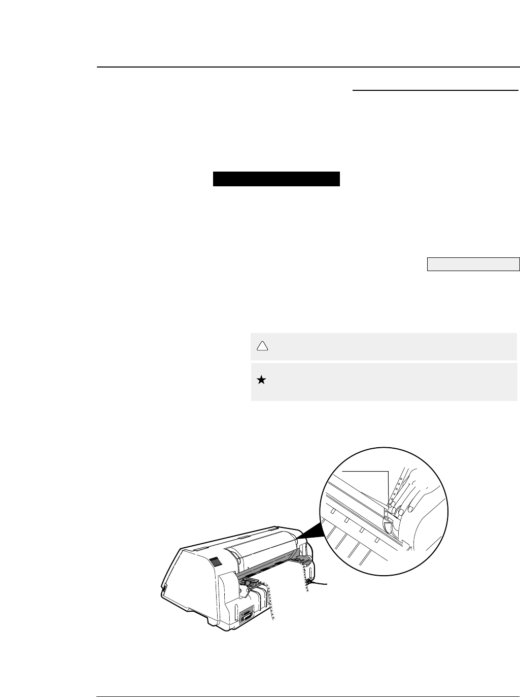
This function feeds the perforation of paper to the paper cutter
position to cut the paper easily. It is useful for ejecting paper
to the top of the printer when the front or rear tractor is used.
Press the TEAR OFF key to feed the perforation to
the paper cutter. Cut the paper, then press the TEAR
OFF key again. The paper is fed back to the
previous position.
To cut the paper fed out from the front of the tractor,
hold the upper cover firmly with one hand and tear
the paper towards you down wards.
4-3
— 4. Functions —
Feeding perforation to the cutter position
See page 2-1.
●
Functions
Operation procedures
Although safe, take care not to brush your fingers
along the edge of the paper cutter.
Caution
Use the paper cutter attached to the upper cover to cut
the paper. Using another part of the printer to cut the
paper forcibly may result in damage to the printer.
Caution
!
1
Paper cutter
4-4
This function controls the line feed speed to feed thick
copying paper more stably.
In the 1/2 or 1/3 mode, line feeding is always carried out at 1/3 or 1/2
speed. This function is useful for printing data on multipart forms.
Select the mode using #66 LF SPEED in the
EXTENDED SETUP MODE.
When the multipart forms are bound by paper staples or paper fasteners,
select FASTENER MODE: YES in the #15 paper fastener mode setting.
When the perforation peak of the multipart fanfold paper is too high, select
HEAD LIFT UP: YES in the #16 the head-up mode setting.
Select the mode using #15 paper fastener mode
setting and #16 perforation head-up mode setting in
the SETUP MODE.
This automatic scroll function feeds the perforation to the
paper cutter position automatically when no data is received
for a preset period.
If the input buffer becomes empty in the ONLINE state and no input data
is received for a preset period (0.5, 1, 5, 10 or 15 seconds), the printer
automatically feeds the perforation at the top of the next page to the paper
cutter position and waits in this standby mode until additional input data is
received.
When the printer receives additional input data in this standby condition, it
reverse feeds paper to the correct print position and resumes printing there.
If the perforation is located at the paper cutter position when the input buffer
becomes empty, no paper motion action occurs.
When TOF ONLY is selected together with #67 AUTO SCROLL
POISITION, auto scrolling takes place only when the present position of the
paper is TOF.
Select a mode using #62 AUTO SCROLL in the EXTENDED
SETUP MODE.
— 4. Functions —
Automatically feeding perforation to the paper cutter
position in the standby condition
See page 3-42.
●
Functions
Operation procedures
See page 3-44.
More stable paper feeding
Operation procedures
Operation procedures
See page 3-22.
Used for restoring settings made in the setup mode to the
factory default settings.
This operation initializes all parameters on the SETUP MODE and
EXTENDED SETUP MODE.
1. Keep the LINE FEED, EJECT/LOAD, PAPER
PATH and PAPER FORM keys depressed, and
turn on the printer.
2. The message shown below is displayed on the
LCD. The EEPROM is initialized.
This operation 2 initializes almost all factory default settings.
EEPROM intialization 2 = EEPROM intialization 1 + learning sensor.
1. Set 15-inch fanfold paper to the front tractors in
the parking position.
2. Keep the ALT. REVERSE LF, PAPER PATH and
PAPER FORM keys depressed, and turn on the
printer.
3. The message shown below is displayed on the
LCD. The EEPROM is initialized.
4-5
— 4. Functions —
EEPROM initialization 1
EEPROM INITIAL 1
●
Functions
Operation procedures
EEPROM initialization 2
Operation procedures
EEPROM INITIAL 2
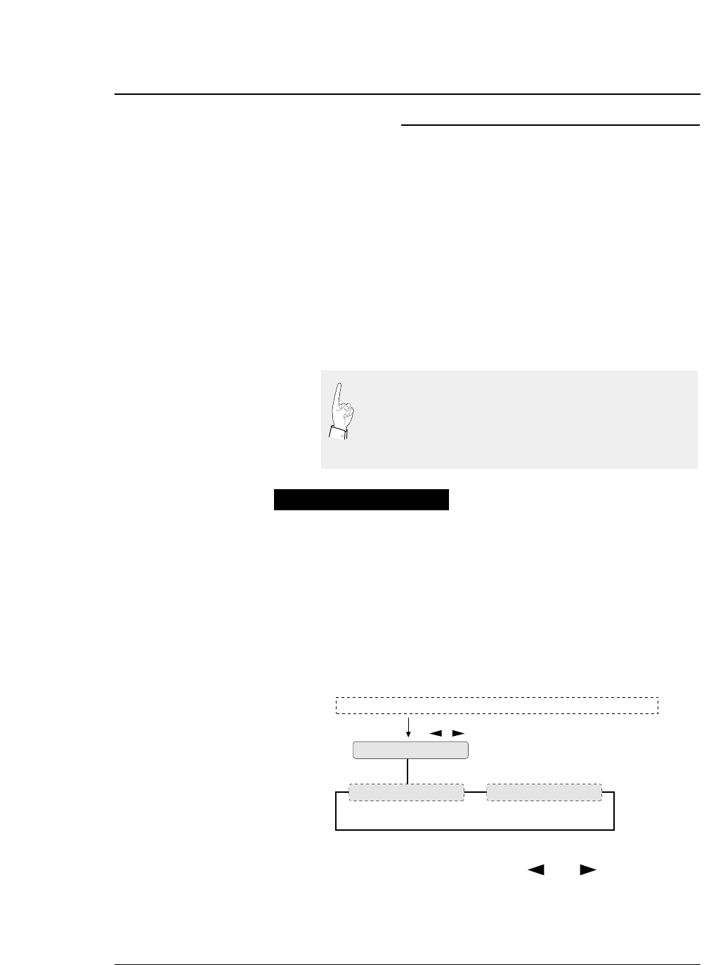
4-6
The printer has two printing adjustment modes to correct misalignment
due to printer instrumentation error or aging deterioration: printing start
position adjustment mode (mode A), and bi-directional printing position
adjustment mode (mode B). These two modes allow the printing position
to be corrected properly.
The printing start position adjustment mode (mode A) corrects
misalignment in the printing start positions for printing at different speeds.
This allows data to be printed at the same start position even at different
printing speeds.
The bi-directional printing position adjustment mode (mode B) corrects
misalignment in bi-directional printing at the same printing speed. It
selects the proper correction value for each printing speed.
1. Set fanfold paper that is 10 inches or more in
width to the printer. Feed one or more pages of
paper and then select this mode.
2. Keep the SET UP and EJECT/LOAD keys
depressed and turn on the printer. The printer
enters the printing position adjustment mode.
3. Select a mode with the
then press the ENTER key.
The procedures shown below are used for both modes A
and B.
— 4. Functions —
Correcting vertical misalignment
A change in mode A has effects mode B. If a change is
made in mode A, mode B must also be set properly. The
printer starts up in mode A and then enters mode B
automatically. If no change is made in mode A, the
printing position can be changed in mode B only.
ALIGN ADJUST
A: START POS.ADJ B: VERT ADJ
Key
Display
Keep SET UP and EJECT/LOAD keys depressed and turn on the printer
Operation procedures
●
Functions
key, or

4. Press the ENTER key and the timing pattern in
mode A (or mode B) will be printed.
Numbers marked with asterisks indicate the currently set
timing numbers. In mode A, modes 1 to 11 are printed. In
mode B, modes 0 to 11 are printed.
In each mode, 13 timing patterns are printed.
5. Select a speed mode number to be changed in the
printed patterns.
6. Select the best aligned pattern in the same speed
mode.
Check the alignment of the two line"H"printing.
7. Then press the ENTER key.
The selected timing is temporarily stored in the printer, and
test printing is executed at that timing.
8. Repeat steps 5 to 7 to change the speed modes.
9. Press the EXIT key to finish setting.
The timing stored temporarily is saved in the setup memory
(EEPROM). Therefore, be sure to press the EXIT key to exit
the mode.
10. Processing when the EXIT key will be pressed
differs according to the mode as shown below.
a. If mode A is exit, the menu of mode B will be displayed.
Press the ENTER key, and the patterns of mode B are
printed. Hereinafter, follow step 5 and so on.
b. If mode B is exit, the printer is reset automatically and
exits mode B.
4-7
— 4. Functions —
A-MODE 1: NO.6
A-MODE 3: NO.6
Select with or key.
For example, mode 1 is changed to mode. 3.
A-MODE 3: NO.6
A-MODE 3: NO.8
Select with or key.
For example, mode 6 is changed to mode 8.
●
Functions
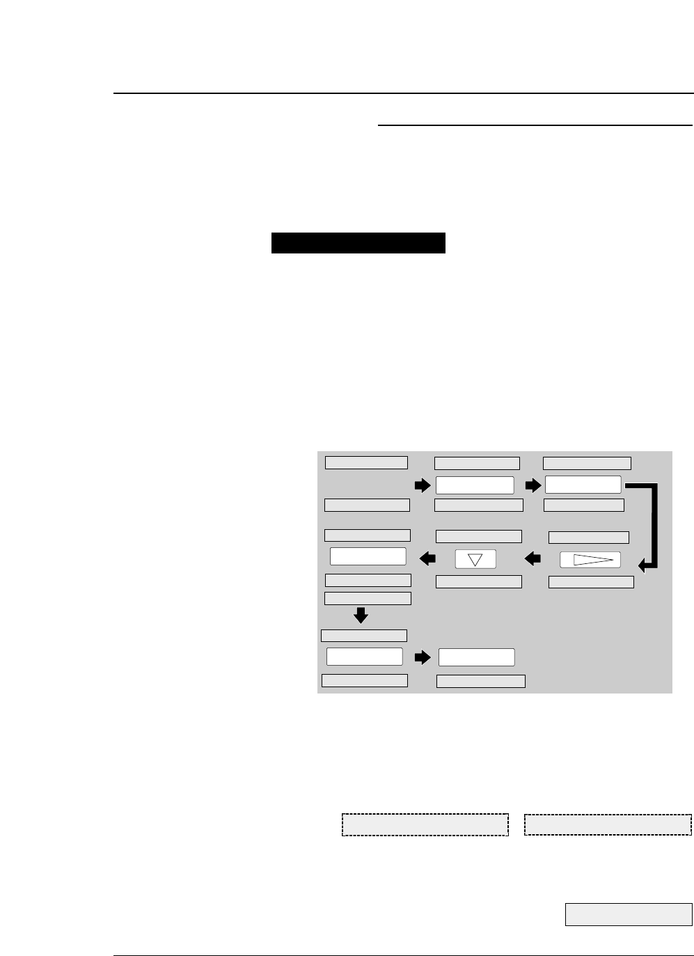
4-8
The printer has six memories for saving data on forms:
MEMO 1 to MEMO 6. The following shows an example of
storing the sizes of three forms used in the manual mode in
MEMO 1 to MEMO 3.
1. Press the PAPER PATH key to select MANUAL →
FRONT.
2. Press the PAPER FORM key to select MEMO 1.
3. Specify the A5 portrait form with #4 PAGE LENGTH
in the SETUP MODE, then save the setting as shown
below.
4. Likewise, specify the Letter portrait form in MEMO 2
and the A3 portrait form in MEMO 3. The following
messages will be displayed on the LCD.
5. In printing, select the MEMO containing the form
size to be used with the PAPER FORM key.
— 4. Functions —
Using various types of paper
MAN FRNT LT p MAN FRNT A3 p
See page 1-11.
PAPER FORM
1 MULTIPART
4 PAGE LENGTH
SIZE: A5 p
PAGE: 11 INCH*
ENTER
SIZE: A5 p
SET UP
1 MULTIPART
SAVE?: YES*
EXIT
PAPER PATH
F.TR. REAR 11x15 MAN FRNT A4 p
ENTER
MAN FRNT A5 p
MAN FRNT 11x15 MAN FRNT A4 p
MAN FRNT 11x15
SIZE: A5 p*
4 PAGE LENGTH
4 PAGE LENGTH
Operation procedures
●
Functions
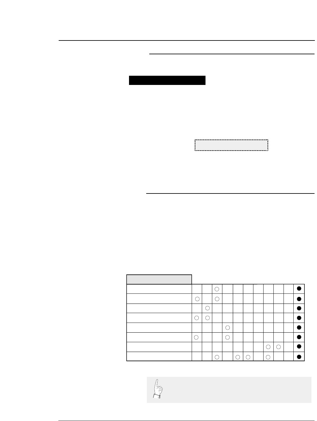
4-9
— 4. Functions —
The printer can execute test printing.
1. Keep the ONLINE and REVERSE LF keys depressed
and turn on the printer.
2. The following message will be displayed on the LCD.
The printer starts test printing.
3. To terminate test printing, turn the power switch to
off.
Key shortcut functions are executed by pressing and holding
the corresponding keys while simultaneously turning on the
printer power. The following table shows the available
shortcut functions.
Executing test printing
Key shortcut functions
DEMO PRINT LQ
Note that, if the EEPROM is initialized, all the data
specified in the EEPROM is deleted.
Operation
Self Test Draft
Self Test LQ
Hex Dump Draft
Hex Dump LQ
Demo Print Draft
Demo Print LQ
Vertical Alignment
EEPROM Initialization
ONLINE
FORM FEED
LINE FEED
REVERSE LF
PAPER FORM
PAPER PATH
TEAR OFF
EJECT/LOAD
SET UP
ALT
Power
Operation procedures
●
Functions

4-10
About Printer
driver
Printer Driver is a section of your software that automatically translates
instructions from the software to your printer.
For example, when using some application softwares, if you want to
boldface or underline a word, the printer driver automatically translates
your specific boldface or underline instruction on your application
software to printer control command.
Different printers use different control codes for designating print styles.
Therefore, it is important that when you install your software, you select
the appropriate printer driver designed for your printer.
Printer driver selection
Select a suitable printer driver from the list of supported printers. This
would include either the Hewlett Packard RuggedWriter 480, Epson LQ-
2550 or IBM 2391. Each of these printer drivers should allow you to
access many of the features on your printer.
If this printer is not listed, look for the following printer drivers. While
this should allow you to print your document with your printer, it probably
will not allow you to access many features of the printer. A few of the
choices you may see are given below in order of preferences.
Hewlett Packard Epson IBM
RuggedWriter 480 LQ-2500/2550 2390/2391
DeskJet 500 LQ-1050/1000 Proprinter XL24E
EX-1000 Proprinter XL24
Proprinter 24P
Notes:
1. Set the emulation type in the extension setup options according to the
selection of printer driver. For example, when you select the Epson
LQ-2550 printer driver, you should set the emulation type to the Epson
mode.
2. If you select the DiskJet 500 printer driver, you should set the #50 PCL
MODE to PCL3+D.
— 4. Functions —
●
Functions
Setting the application software

●
Functions
Installing the Windows Printer Driver
The diskette provided with your printer contains the software you need to
operate your printer with Windows applications. Before you install the
printer driver, we recommend you to read the README.TXT file on the
diskette. The README.TXT file contains all the information necessary
to install the printer driver, as well as all other pertinent information
regarding this software.
The printer driver tells Windows what information to send to the printer,
including details about printer features, the printer interface, and fonts.
Follow the next procedure before installing the Windows printer driver.
1. Close all Windows applications. Otherwise you will get an error
message when you attempt to install the printer driver.
2. Set the following parameters of Memo 1-6 to the factory default setting
in the SETUP MODE.
#3 TOF ADJUSTMENT 14/60 inch
#6 TOP MARGIN 0 LINE
#7 BOTTOM MARGIN 0 LINE
#8 LEFT MARGIN 0 CHAR
#9 RIGHT MARGIN 0 CHAR
#10 QUALITY LQ
#12 CHARACTER PITCH 10 CPI
#13 LF PITCH 6 LPI
#14 ZOOM IN/OUT 100 %
Set the following parameters to the factory default setting in the
EXTENDED SETUP MODE.
#20 EMULATION EPSON
#27 CR SETTING CR ONLY
#28 LF SETTING LF + CR
#32 PAGE LENGTH LOCK NO
#33 FONT LOCK NO
#34 PITCH LOCK NO
#35 QUALITY LOCK NO
#36 CHARACTER TABLE LOCK NO
#44 SOFTWARE SETUP VALID
IMPORTANT INFORMATION
1. COPYING RESTRICTIONS:
You may copy this software under certain restrictions. You may make
a backup copy or copy onto a hard disk. No more than two (2) copies
of this software are permitted to be in existence at any one time.
Every copy must include all notices and markings contained in the
original provided by SEIKO Precision Inc.
2. NO LIABILITY FOR CONSEQUENTIAL DAMAGES:
In no event shall SEIKO Precision Inc. be liable for any special,
indirect, incidental, or consequential damages in any way relating to
the use or rising out of the use of this software.
4-11
— 4. Functions —

4-12
Introduction
The HP emulation of the printer provides full compatibility with the
HP2235A RuggedWriter 480 printer.
The printer also provides features and capabilities beyond those ever
provided by the HP RuggedWriter printer. SEIKO Precision Inc. has
provided a means for you to access these extra capabilities for any new
applications that you may chose to print on the printer.
The extra capabilities of the printer are enabled for access through a
special control panel menu setting entitled "50 PCL MODE".
PCL Mode
• PCL3 MODE -Provides the basic RuggedWriter 480 emulation
command set.
• PCL3+ MODE –Provides extra capability to the RuggedWriter 480
command set that allows you to access many printer features through
extensions of the command set.
• PCL3+D MODE –Provides all features of PCL3+ and allows the vertical
and horizontal positioning to be set in increments of 1/360". This mode
provides a "limited" Deskjet capability, and is mainly intended for
printing from Windows using the Deskjet 500 driver. Print output from
this mode will not be identical to that of a Deskjet printer (300 vs. 360
dpi) but will be closer than the other 2 modes for this type of application.
Setup
The information provided below gives setup information of the basic
printer RuggedWriter emulation, details of the command set extensions
provided with PCL3+ and PCL3+D Mode, and information on configuring
the Serial I/O to the various Term Types used by the HP System.
Refer to the Setup options for details on using the SETUP and
EXTENDED SETUP MODE.
Configuring the Printer with the RuggedWriter Emulation
1. Set the #20 EMULATION on EXTENDED SETUP MODE to "HP".
2. Set the #50 PCL MODE on EXTENDED SETUP MODE to "PCL3".
Setting the PCL MODE to "PCL3" provides the command set identical
with that of the HP RuggedWriter 480.
— 4. Functions —
●
Functions
Connecting the printer in the HP environment
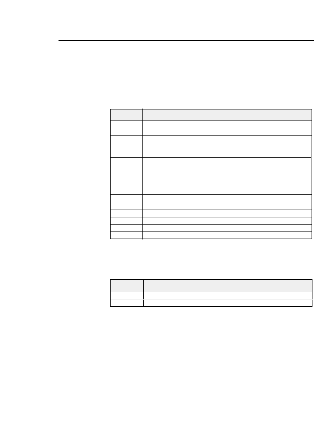
Extra Capabilities for new Applications
Listed below is a summary of the expanded command sets available for
new applications. Refer to the HP software commands for details of using
the expanded command sets.
PCL3+ Mode
This operation mode provides the following extended capabilities:
PCL3+D Mode
This mode provides all of the capabilities described above plus the
following:
4-13
— 4. Functions —
●
Functions
Escape Description Added Capability
Command
BEL Activates the printer's bell Bell is now active.
ESC & k # W Controls the print direction Unidirectional, Bidirectional, Predirectional
ESC ( # id Assign the primary font PC-850, ISO25, France 2, German2,
Spain 3, Legal, Math7, Math-Symbol,
ISO84 Portugal 2, ISO85 Spain 2
ESC ) # id Assign the secondary font PC-850, ISO25, France 2, German2,
Spain 3, Legal, Math7, Math-Symbol,
ISO84 Portugal 2, ISO85 Spain 2
ESC ( s # H Sets the character pitch 15, 17.1, 24 cpi
(primary)
ESC ) s # H Sets the character pitch 15, 17.1, 24 cpi
(secondary)
ESC ( s # T Sets the primary typeface Script, Orator, Orator-s, OCR-A, OCR-B
ESC ) s # T Sets the secondary typeface Script, Orator, Orator-s, OCR-A, OCR-B
ESC * b # M Select graphics data compression Off, Mode1, Mode2, Mode3
ESC * t # R Designates raster graphics resolution 60, 360 dpi
Escape Description Added Capability
Command
ESC * p # X Sets horizontal positioning by dot 1/360"
ESC * p # Y Sets vertical positioning by dot 1/360"

4-14
Serial I/O -Configuring Term Types 18, 19, 21, 22, or 26
The printer may be attached as a spooled printer on your system. It
supports I/O status checking by responding to the interrogation string ESC
? DC1 and indicates its status concerning whether paper is loaded, printer
covers are closed, and whether or not the printer is ONLINE.
Use the printer's EXTENDED SETUP MODE to configure the following
parameters to match your host system settings:
70 INTERFACE Set to SERIAL
72 PARITY Set to match your host configuration as
NONE, EVEN or ODD match your host
setting
73 DATA LENGTH Set to match your host configuration
(Either 7 or 8 BITS)
74 STOP BIT Set to match your host configuration
(Either 1 or 2 BITS)
75 PROTOCOL Set to XON/XOFF 1
76 BAUD RATE Set to match your host configuration as
300,600,1200,2400,4800,9600,19200, or
38400
— 4. Functions —
●
Functions
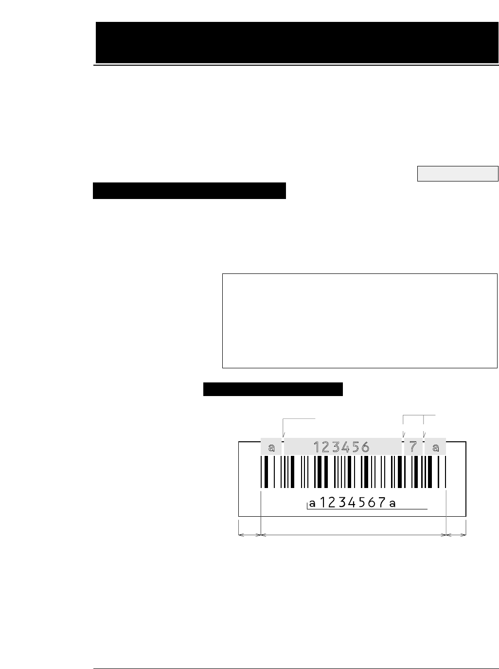
5-1
— 5. Bar code and enlarged character function —
The printer has 14 types of bar codes.
Software commands and options #40 to #42 on the EXTENDED
SETUP MODE are used to print bar codes and enlarged characters.
The software commands are unique to the printer. See the following
pages for details of these commands.
The printer can print bar codes and enlarged characters.
To activate the bar code and enlarged character function, set #40
BARCODE/ENLARGED CHAR to MODE 1 or MODE 2 in the
EXTENDED SETUP MODE.
This function is applicable to the EPSON or IBM or HP mode. This
section describes the outline and details of the bar code and enlarged
character function.
Outline of bar code function
1.Industrial 2 of 5 8.Code 128
2.Interleaved 2 of 5 9.EAN-8
3.Matrix 2 of 5 10.EAN-13
4.Codabar 11.UPC-A
5.Code 11 12.UPC-E
6.Code 39 13.Postnet
7.Code 93 14. Element (Created in elements.)
Makeup of bar code
See page 3-36.
(Example) CODABAR
START
Character DATA
STOP
Character
Margin MarginBarcode
HRI
ICG ICG
Check
Character
Start Character : Initial character of data
DATA : Alphanumeric data
Check Character : Character for check errors in read data
Stop Character : Last character of data
HRI : Human Readable Interpretation
ICG : Gap between characters (Inter Character Gap)
Margin : Data-free portions must be provided on both sides.
Each data-free portion must be approximately ten
times as wide as the narrow space (NS).
5. Bar code and enlarged character
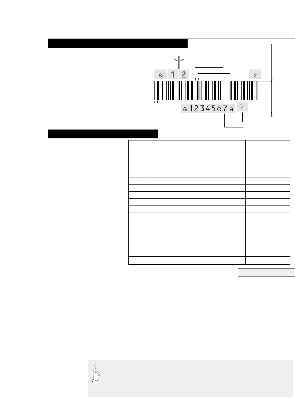
5-2 — 5. Bar code and enlarged character function —
(1) DC4 DC4 T Bar code type:
Format: ASCII DC4 DC4 T n
Hex 14 14 54 n
Decimal 20 20 84 n
Function: Specifies the bar code type
n =0 Industrial 2 of 5 7 Code128
1 Interleaved 2 of 5 8 EAN-8
2 Matrix 2 of 5 9 EAN-13
3 Codabar 10 UPC-A
4 Code11 11 UPC-E
5 Code39 12 Postnet
6 Code93 255 Element Print
Parameter 255 (Element print) is used to print a bar code which is input element by
element. It can print a bar code which is not supported by the printer and is represented
by combining elements. Since data is input by elements, HRI printing is not performed
and no check digit is added to the bar code. The start and stop characters is also not
added.
See pages 3-37 and 3-38.
Function Command
1. Bar code type DC4 DC4 T
2. Element width DC4 DC4 E
3. Bar code height DC4 DC4 H
4. Setting HRI on and off DC4 DC4 I
5. HRI font DC4 DC4 F
6. Check character DC4 DC4 C
7. Starting the bar code data sequence ESC SI
8. Ending the bar code data seqence ESC SO
9. Bar code data sequence DC4 DC4 B
10. Printing density DC4 DC4 D
11. Guard bar expansion DC4 DC4 G
12. Start and stop characters DC4 DC4 N
13. Bar code rotational angle DC4 DC4 R
14. Disabling HRI of the start and stop characters DC4 DC4 S
15. Value input mode DC4 DC4 V
16. Initializing the bar code mode DC4 DC4 @
(Example) CODABAR
Narrow Space
Narrow Bar
START
Character STOP
Character
Wide Space
Wide Bar
Inter Character Gap
Barcode Height
Check Character
HRI
Presettable bar code function list
Bar code command list
●
Bar code function

5-3
— 5. Bar code and enlarged character function —
(2) Element width: DC4 DC4 E
Format: ASCII DC4 DC4 E n1 n2
Hex 14 14 45 n1 n2
Decimal 20 20 69 n1 n2
Function:
Specifies the n2/120” or n2/180” width of the element n1.
(1 ≤n 2 ≤127)
120” or 180” is specified with the DC4 DC4 D command.
n1 = 0: Narrow bar 3: Wide space
1: Wide bar 4: Inter-character gap
2: Narrow space
The narrow bar width or narrow space is used as the element width for
Code 93, Code 128, EAN-8, EAN-13, UPC-A, and UPC-E.
One element width of bar 1: Narrow bar width
One element width of space 1: Narrow space width
The midium bar or wide space width is used as the midium element width
for Code 11. The wide element width is (wide bar width x 2 - narrow bar
width).
This setting is not valid for Postnet.
The inter-character gap means the space between each set of codes of a bar
code which begins with a bar and ends with a bar.
(3) Bar code height: DC4 DC4 H
Format: ASCII DC4 DC4 H n
Hex 14 14 48 n
Decimal 20 20 72 n
Function: Sets the bar code height to n/12”. (0 ≤n ≤120)
The currently set line feed pitch serves as the bar code height when n
is set to 0. This setting is not valid for Postnet.
(4) Setting HRI on and off: DC4 DC4 I
Format: ASCII DC4 DC4 I n
Hex 14 14 49 n
Decimal 20 20 73 n
Function: Specifies whether or not to print an HRI. Also specifies the
HRI printing position if an HRI is to be printed.
n = 0: HRI not printed.
1: HRI printed below the bar code symbol.
2: HRI printed above the bar code symbol.
No HRI printed for Postnet or Element regardless of this setting.
See page 5-9.
●
Bar code function

5-4 — 5. Bar code and enlarged character function —
(5) HRI font: DC4 DC4 F
Format: ASCII DC4 DC4 F n
Hex 14 14 46 n
Decimal 20 20 70 n
Function: Selects the font of printing the HRI.
n = 0: Currently selected font
1: OCR-A
2: OCR-B
This setting is not valid for Postnet or Element.
(6) Check character: DC4 DC4 C
Format: ASCII DC4 DC4 C n
Hex 14 14 43 n
Decimal 20 20 67 n
Function: Specifies whether to add a check character automatically.
n = 0: No check character is added. (If a check character is needed, the
user must send bar code data.)
1: A check character is added. (The check character is not printed
in the HRI when Code 93 or Code 128 is selected.)
If the Codabar or Element is selected, no check character is added regardless of
this setting.
The following shows the methods of determining the check characters and bar
code types. (For details, see “Calculating the check character” below.)
Modulus 10 Industrial 2 of 5, Interleaved 2 of 5, Matrix 2 of 5, EAN, UPC,
Postnet
Modulus 11 Code 11 (Dual Check character)
Modulus 16 Codabar
Modulus 43 Code 39
Modulus 47 Code 93 (Dual Check character)
Modulus 103 Code 128
(7) Beginning of the bar code data sequence: ESC SI
Format: ASCII ESC SI
Hex 1B 0F
Decimal 27 15
Function: Indicates the beginning of a bar code data sequence.
Data between this and the end command of the bar code data sequence
is regarded as bar code data.
This command is valid only when #40 BARCODE/ENLARGED
CHAR is set to MODE 2 in the EXTENDED SETUP MODE.
See pages 5-12 and -13.
●
Bar code function

5-5
— 5. Bar code and enlarged character function —
(8) End of the bar code data sequence: ESC SO
Format: ASCII ESC SO
Hex 1B 0E
Decimal 27 14
Function: Indicates the end of a bar code data sequence.
This command is valid only when #40 BARCODE/ENLARGED CHAR is
set to MODE 2 in the EXTENDED SETUP MODE.
(9) Bar code data sequence: DC4 DC4 B
Format: ASCII DC4 DC4 B n d1 d2 ... dk
Hex 14 14 42 n
Decimal 20 20 66 n
Function: Specifies the number (“n”) of data to be regarded as bar code data.
00
≤n ≤
68
00
≤dk ≤
255
00
≤k ≤
68
If the Element is selected; 0 ≤n, dk, k ≤
255
This comand is valid when #40 BARCODE/ENLARGED CHAR is set to MODE 1
or MODE 2 in the EXTENDED SETUP MODE.
(10) Printing density: DC4 DC4 D
Format: ASCII DC4 DC4 D n
Hex 14 14 44 n
Decimal 20 20 68 n
Function: Specifies the density of printing bar code symbols (in the horizontal
direction).
Specifies the unit of element width.
n = 0: Bar code symbols are printed at 120 dpi. (Default value)
1: Bar code symbols are printed at 180 dpi.
If a bar code is rotated by 90 or 270 degrees using the DC4 DC4 R (bar code
rotational angle) command, a bar code is printed at 120 dpi horizontally and 180 dpi
vertically.
(11) Guard bar expansion: DC4 DC4 G
Format: ASCII DC4 DC4 G n
Hex 14 14 47 n
Decimal 20 20 71 n
Function: Specifies whether or not to expand EAN or UPC guard bars.
n = 0: Guard bars are not expanded.
1: Guard bars are expanded. (Default value)
●
Bar code function

5-6 — 5. Bar code and enlarged character function —
(12) Start and stop characters: DC4 DC4 N
Format: ASCII DC4 DC4 N n1 n2
Hex 14 14 4E n1 n2
Decimal 20 20 78 n1 n2
Function: Specifies the Codabar start or stop character. n1 selects the
start or stop character. n2 specifies a code of the start or stop character
as shown below.
n1 = 0: Start character
1: Stop character
n2 = a, b, c, d, t, n, ✽, or e.
When power is turned on, “a” is selected as the start or stop character.
(13) Bar code rotational angle: DC4 DC4 R
Format: ASCII DC4 DC4 R n
Hex 14 14 52 n
Decimal 20 20 82 n
Function: Specifies the rotational angle of the bar code in units of 90 degrees.
n = 0: 0°(Default value)
1: 90°
2: 180°
3: 270°
(14) Disabling HRI of the start and stop characters: DC4 DC4 S
Format: ASCII DC4 DC4 S n
Hex 14 14 53 n
Decimal 20 20 83 n
Function: Specifies whether or not to print the start or stop character in the HRI
for Codabar, Code 11, Code 39 or Code 93.
n = 0: The start or stop character is printed in the HRI.
(Default value)
1: The start or stop character is not printed in the HRI.
(15) Value input mode: DC4 DC4 V
Format: ASCII DC4 DC4 V n
Hex 14 14 56 n
Decimal 20 20 86 n
Function: Specifies whether bar code sequence data is regarded as the normal
character code or a character value when Code 128 is selected.
n = 0: Data is regarded as normal character code. (Default value)
1: Data is regarded as a character value.
If data is regarded as the normal character code, the printer
automatically move the subset or inserts a shift code according to
the data.
See page 5-11.
●
Bar code function

●
Bar code function
5-7
— 5. Bar code and enlarged character function —
(16) Initializing the bar code mode: DC4 DC4 @
Format: ASCII DC4 DC4 @
Hex 14 14 40
Decimal 20 20 64
Function: Initializes the bar code mode.
The following show the default settings for bar code.
Bar code type: SETUP
Narrow bar width: SETUP
Wide bar width: SETUP
Narrow space width: SETUP
Wide space width: SETUP
Inter- character gap: SETUP
Bar code height: SETUP
Setting HRI: Below the bar code symbol
HRI font OCR-B
Check character: Added
Printing density: 1/120”
●
In a bar code data sequence, any codes other than the ESC
code are regarded as bar code data.
In a bar cord sequence following ESC SI, continuous two-
byte ESC codes (ESC + ESC) are regarded as a one-byte
ESC bar code.
●
In a barcode data sequence following ESC SI, ESC+ SO
and ESC + ESC are valid and the other ESC sequence are
ingnored. The ESC code and the following data, two bytes
in all, are discarded.
●
When a start or stop character code (e.g., *code of Code
39) is input in a bar code data sequence, the bar code data
sequence stops if bar code data has already been input in
that sequence. The data that was input is valid and
converted into a bar code. If not, the bar code data
sequence does not stop and the code is discarded.
●
When 68 bytes of data is input, the bar code data sequence
ends automatically.
When Code 93 or Code 128 is selected, the bar code data
sequence ends when the amount of input data, including the
automatically inserted control character, reaches 68 bytes.
(Bar code buffer full)
Data processing in the bar code data sequence

5-8 — 5. Bar code and enlarged character function —
●
Bar codes are printed at normal LQ 10 cpi (158 cps) print
speed when the printing density is 120 dpi or at Dark 1 LQ
10 cpi (79 cps) print speed when the printing density is 180
dpi. This does not apply to printing paths involving HRI
printing or duty control.
●
Bar codes and normal characters are printed separately.
When the bar code data sequence is processed, print data
other than bar code data contained in the buffer is printed.
When print data other than bar code data is input, bar
code data contained in the buffer is printed.
●
Like the right margin overflow processing for character
data, data preceding bar code data is printed and the bar
code data is printed from the left margin on the following
line if the data exceeds the right margin.
If bar code data cannot be printed between the left and
right margins, the bar code data is ignored.
●
When the number of bar code symbols in the buffer
reaches 68, printing starts. (Bar code buffer full printing)
●
If the vertical line feed pitch is smaller than the bar code
height, reverse feeding is performed to move to the
following printing position.
●
If an out-of-paper error is detected in a bar code printing
path, the following paths are printed on the following
form.
Printing bar codes
●
Bar code function

5-9
— 5. Bar code and enlarged character function —
●
The HRI is adjusted to the center of the bar code symbol
width and printed at 10 cpi unless EAN or UPC guard bar
expansion is executed. If EAN or UPC guard bar
expansion is executed, an HRI is printed at the equal space
between the center guard bar and the left or right guard
bar.
If the HRI width is greater than the bar code symbol width,
the HRI printing pitch is reduced to print the HRI in the
same width as the bar code symbol width.
●
The HRI is printed below a bar code symbol, the vertical
printing position is lower than the printing start position
by (bar code height - 1/6”). If it is printed above the bar
code symbol, the vertical printing position is higher than
the printing start position by (1/6” - 24/180”).
●
When Code 11 is selected, small triangle (
▲▲
) and large
triangle (
▲▲
) are printed as the start and stop characters,
respectively. (This does not depend on the setting of the
check character.)
●
When Code 93 is selected, white squares (
■■
) are printed
as the start and stop characters, and a black square (
■
) is
printed as the control character. A printable character
expressed in combination with the control character is
printed as is. (For example, 61H is printed as ‘a’, not ‘
■
A’.)
●
When Code 128 is selected, black rhombuses (
◆
) are
printed instead of non-printable characters (00H to IFH
and 7FH).
H R I
●
Bar code function

5-10 — 5. Bar code and enlarged character function —
●
If a character code that is not valid for the selected bar
code type is input, the character code is not converted into
a bar code symbol but is printed as a character. If the bar
code has a start or stop character added to the HRI, the
start or stop character is printed. ‘ ’ is printed instead
of an invalid character.
●
If an incorrect number of data are input to form a bar code
which should have a specific number of data, the input
data is not converted into a bar code symbol but is printed
as a character.
●
If incorrect data is input in the UPC-A format and cannot
be converted into the UPC-E format, the input data is not
converted into a bar code symbol but is printed as a
character. (For the rules of converting the UPC-A format
into the UPC-E format, see “UPC-E conversion rule”
below.)
Error processing
●
Bar code function

5-11
— 5. Bar code and enlarged character function —
●
The following shows the transition conditions from subset
A to subset B.
1. Input a character code unique to subset B (60H
to 7FH) when subset A is selected.
2. Then input a character code unique to subset B
(60H to 7FH) without inputting a character code
unique to subset A (00H to 1FH). (If a character
code unique to subset A is input in this step,
subset B is not selected. The character code
unique to subset B input in step 1 is expressed
with the shift code.)
●
The following shows the transition conditions from subset
B to subset A.
1. Input a character code unique to subset A when
subset B is selected.
2. Then input a character code unique to subset A
without inputting a character code unique to
subset B. (If a character code unique to subset B
is input in this step, subset A is not selected. The
character code unique to subset A input in step 1
is expressed with the shift code.)
●
Subset C is selected when four continuous character codes
(30H to 39H) are input.
●
If a code common to subset A and subset B is input when a
subset is not determined or subset C is selected, subset B is
temporarily selected.
Code 128 subset transition rule
●
Bar code function
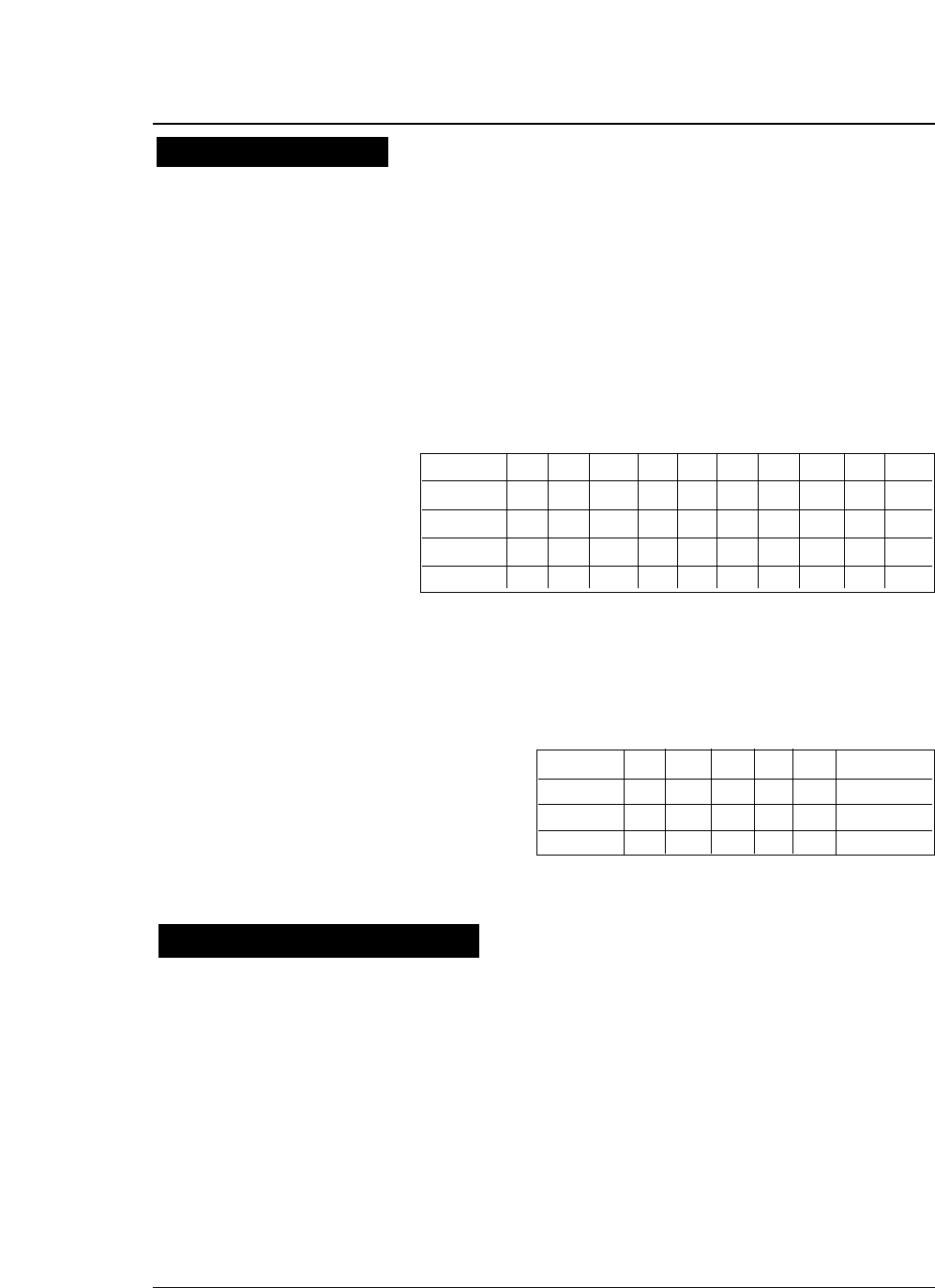
5-12 — 5. Bar code and enlarged character function —
●
NSC, manufacturer’s codes (M1 M2 M3 M4 M5), and
product item codes (X1 X2 X3 X4 X5) are input data.
1.
NSC must be 0 or 1.
2.
When the manufacturer’s code data is input,
the rule is determined and zero checking of the
product item codes is performed.
NZ: Non-zero ✽: 0 to 9
UCP-A Type
3.
The following table shows print data if the rule
shown above is met.
UCP-E Type
• Modulus 10
a. The data at the odd-numbered position counted from the right are
weighed as 3. The sum of the data character values is determined..
(The sum is determined without weighing for Postnet.)
b. The remainder after dividing the value determined in step a by 10 is
determined.
c. The check character is the character value determind by subtracting
the remainder in step b from 10.
UPC-E conversion rule
M1 M2 M3 M4 M5 X1 X2 X3 X4 X5
Rule 1✽✽✽✽
NZ 00005~ 9
Rule 2✽✽✽
NZ 00000✽
Rule 3✽✽
3~ 900000✽✽
Rule 4✽✽
0~ 20000✽✽✽
Rule 1M1 M2 M3 M4 M5 X5 (5 ~ 9)
Rule 2M1 M2 M3 M4 X5 '4'
Rule 3M1 M2 M3 X4 X5 '3'
Rule 4M1 M2 X3 X4 X5 M3 (0 ~ 2)
Calculating the check character
●
Bar code function

5-13
— 5. Bar code and enlarged character function —
• Modulus 11
a. Data characters are weighed from the right to the left, as,
example,1, 2, ..., 10, 1, 2 ... 10, 1, 2 and so forth. The sum of
the data character values is determined. (The symbol ‘-’ has a
character value of 10.)
b. A character having a character value equal to the remainder of
dividing the value determined in step a by 11 is the first check
character (C).
c. Data characters are weighed from the right to the left,
beginning with C, as, for example, 1, 2, ..., 9, 1, 2 ... , 9, 1, 2
and so forth. The sum of the data character values is
determined.
d. The character with a character value equal to the remainder of
dividing the value determined in step c by 11 is the second
check character (K).
• Modulus 16
a. The sum of the all characters including start and stop
characters values is determined. The following table shows the
conversion of character into value.
Value Character Value Character Value Charactr Value Character
00 1 1 2 2 3 3
44 5 5 6 6 7 7
88 9 9 10- 11$
12 : 13 / 14 . 15 +
16 A 17 B 18 C 19 D
b. The remainder X of deviding the value determined in step a
by 16 is determined. The remainder Y of subtracting the
remainder X from 16 is determined.
c. Convert the remainder Y into the character Z according to the
conversion table in a. The character Z is the check character.
• Modulus 43
a. The sum of the data character values is determined.
b. The character with a character value equal to the remainder of
dividing the value determined in step a by 43 is the check
character.
●
Bar code function

5-14 — 5. Bar code and enlarged character function —
• Modulus 47
a. Data characters are weighed from the right to the left, as, for
example, 1, 2, ..., 20, 1, 2 ... 20, 1, 2 and so forth. The sum of
the data character values determined..
b. The character with a character value equal to the remainder of
dividing the value determined in step a by 47 is the first check
character (C).
c. Data characters are weighed from the right to the left,
beginning with C, as, for example, 1, 2, ..., 15, 1, 2 ... , 15, 1, 2
and so forth. The sum of the data character values is
determined.
d. The character with a character value equal to the remainder of
dividing the value found in step c by 47 is the second check
character (K).
• Modulus 103
a. The sum of the products of the data character values and
position values is determined. (The leftmost character has a
position value of 1.)
b. The start character value is added to the sum determined in
step a above.
c. The character with a character value equal to the remainder
of dividing the value determined in step c by 103 is the check
character.
●
After executing a BS command input immediately after bar
code data, printing starts from the position by one
character to the left of the currently set character pitch.
●
When a margin is specified, bar code data in the buffer is
cleared.
●
The element printing function prints bar codes by inputting
data element by element.
●
This function allows the user to print bar codes which are
not supported by the printer but are expressed by
combining elements. No HRI is printed, no check digit is
added, and a start or stop character is not added, since
data is input element by element.
●
The following show the codes expressing elements.
00H: Narrow bar
01H: Wide bar
02H: Narrow space
03H: Wide space
04H: Inter-character gap
Other
Element printing
●
Bar code function

5-15
— 5. Bar code and enlarged character function —
[Example]
The following shows a BASIC program for printing Code 39 bar codes
using the element printing function. This example shows how to print
“CODE39”. (Replace NB, WB, NS and WS in the data statements in the
following example with 0, 1, 2 and 3, respectively.)
100 OPEN "LPT1:" AS #1: WIDTH #1,255
110 DC4$=CHR$ (&H14): ESC$=CHR$(&H1B)
120 SI$=CHR$(&HF):SO$=CHR$(&HE): ICG=4
130 '
140 PRINT #1, DC4$;DC4$;"@"; ' Initialize
150 PRINT #1, DC4$;DC4$;"T";CHR$(255); ' Barcode Type: Element Print
160 PRINT #1, DC4$;DC4$;"E";CHR$(0);CHR$(2); ' Narrow Bar: 2/120"
170 PRINT #1, DC4$;DC4$;"E";CHR$(1);CHR$(6); ' Wide Bar: 6/120"
180 PRINT #1, DC4$;DC4$;"E";CHR$(2);CHR$(2); ' Narrow Space: 2/120"
190 PRINT #1, DC4$;DC4$;"E";CHR$(3);CHR$(6); ' Wide Space: 6/120"
200 PRINT #1, DC4$;DC4$;"E";CHR$(4);CHR$(2); ' Inter Char Gap: 2/120"
210 PRINT #1, DC4$;DC4$;"H";CHR$(6); ' Barcode Height: 6/12"
220 '
230 PRINT #1, DC4$;DC4$;"B";CHR$(9*8+7); ' Barcode Data Sequence Start
240 RESTORE 440
250 FOR I=1 TO 9:READ A:PRINT CHR$(A);:NEXT I
260 PRINT #1, CHR$(ICG);
270 FOR J=1 TO 6
280 IF J=1 THEN RESTORE 450
290 IF J=2 THEN RESTORE 460
300 IF J=3 THEN RESTORE 470
310 IF J=4 THEN RESTORE 480
320 IF J=5 THEN RESTORE 490
330 IF J=6 THEN RESTORE 500
340 FOR I=1 TO 9:READ A: PRINT #1, CHR$(A);:NEXT I
350 PRINT #1, CHR$(ICG);
360 NEXT J
370 RESTORE 440
380 FOR I=1 TO 9:READ A: PRINT #1, CHR$(A);:NEXT I
400 PRINT #1,CHR$(13);CHR$(10); ' CR+LF
410 CLOSE #1
420 END
430 '
440 DATA 0, 3, 0, 2, 1, 2, 1, 2, 0
450 DATA 1, 2, 1, 2, 0, 3, 0, 2, 0
460 DATA 1, 2, 0, 2, 1, 2, 0, 3, 0
470 DATA 0, 2, 0, 2, 1, 3, 0, 2, 1
480 DATA 1, 2, 0, 2, 1, 3, 0, 2, 0
490 DATA 1, 2, 1, 3, 0, 2, 0, 2, 0
500 DATA 0, 2, 1, 3, 0, 2, 1 ,2, 0
Element printing
●
Bar code function
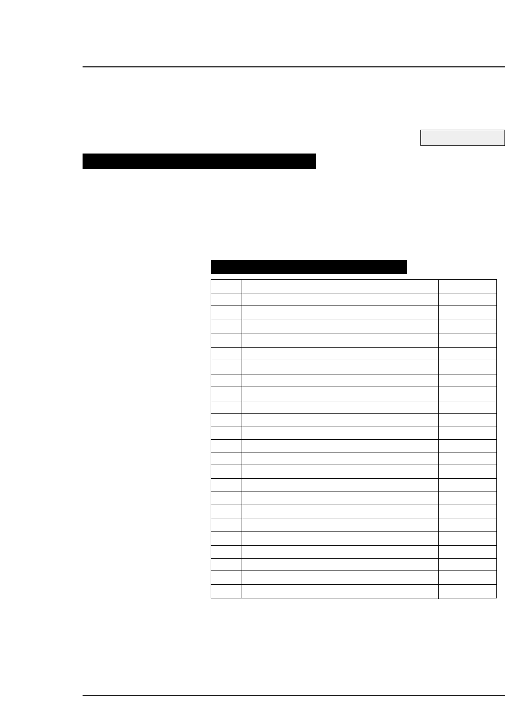
If #40 BARCODE/ENLARGED CHAR is set to MODE 1 or MODE 2
in the EXTENDED SETUP MODE, enlarged characters can be
printed. The enlarged character function is valid for the EPSON or
IBM or HP mode.
5-16
When the enlarged character mode is selected with the DC4 DC4 I 1
command, any commands other than those shown below are ignored.
Only three print codes are available: LF, CR and FF. If 521 or more
characters of data are sent without inputting a print command, printing
is performed automatically.
Function Command
1.
Executing backspacing
BS
2.
Executing line feeding
LF
3.
Executing form feeding
FF
4.
Executing carriage return
CR
5.
Initializing the enlarged character mode
DC4 DC4 @
6.
Arrangement of enlarged characters
DC4 DC4 a
7.
Element magnification for enlarged characters
DC4 DC4 c
8.
All-character set for enlarged characters
DC4 DC4 d
9.
Selecting an enlarged character font
DC4 DC4 f
10.
Height expansion for enlarged characters
DC4 DC4 h
11.
HMI for enlarged characters
DC4 DC4 i
12.
VMI for enlarged characters
DC4 DC4 j
13.
Setting and canceling the enlarged character mode
DC4 DC4 l
14.
Enlarged character cell offset
DC4 DC4 o
15.
Enlarged character pitch
DC4 DC4 p
16.
Enlarged character quality
DC4 DC4 q
17.
Enlarged character rotational angle
DC4 DC4 r
18.
Setting and canceling enlarged character smoothing
DC4 DC4 s
19.
Enlarged character top offset
DC4 DC4 t
20.
Setting and canceling underscores for enlarged characters
DC4 DC4 u
21. Enlarged character width expansion DC4 DC4 w
22. Horizontal printing position for enlarged characters DC4 DC4 x
23. Vertical printing position for enlarged characters DC4 DC4 y
Outline of enlarged character function
Enlarged character command list
●
Enlarged character function
See page 3-36.
— 5. Bar code and enlarged character function —

5-17
— 5. Bar code and enlarged character function —
(1) Executing backspacing: BS
Format: ASCII BS
Hex 08
Decimal 08
Function: Executes backspacing.
When the BS command is executed, the printing position moves to the
previous character position on the left. The BS command is valid up to the
left margin. A BS command issued on the left margin is ignored.
When a BS command is issued when there is a character on the left with
proportional printing selected, the printer backspaces to that character. If
there is no character or another BS command has just been executed, the
printer backspaces by one space.
The part moved by backspacing is not underscored.
(2) Executing line feeding: LF
Format: ASCII LF
Hex 0A
Decimal 10
Function: Executes line feeding.
After printing data, the printer feeds one line by the enlarged character line
feed pitch, which differs depending on whether VMI is valid (by the DC4
DC4 j command) or not.
VMI valid: Preset VMI amount
VMI not valid: (24 + cell offset)/180” x cell expansion
Line feeding involves a carriage return if the LF SETTING option is set to
LF + CR in the EXTENDED SETUP MODE.
If the bottom margin is specified and the cell size (i.e., 24/180” x cell
expansion) is greater than the printable area in the CSF, cut sheet, or
fanfold paper mode, form feeding is executed and then printing is executed.
If the printing position is at the TOF position, printing is executed up to the
bottom margin without executing form feeding, and excess data is not
printed.
The default pitch is “1/6” x cell expansion”.
●
Enlarged character function

5-18 — 5. Bar code and enlarged character function —
(3) Executing form feeding: FF
Format: ASCII FF
Hex 0C
Decimal 12
Function: Executes form feeding.
This command feeds the page to the next TOF position. If there are still enlarged
characters to be printed, they are printed, then form feeding is executed.
(4) Executing carriage return: CR
Format: ASCII CR
Hex 0D
Decimal 13
Function: Executes carriage return.
This command moves the printing position to the left margin without printing any
characters. If the CR SETTING option is set to CR + LF in the EXTENDED
SETUP MODE, a carriage return is executed out after printing.
(5) Initializing the enlarged character mode: DC4 DC4 @
Format: ASCII DC4 DC4 @
Hex 14 14 40
Decimal 20 20 64
Function: Initializes the enlarged character mode.
The following show the default settings for enlarged characters:
Cell expansion: SETUP expansion
Height expansion: SETUP expansion
Width expansion: SETUP expansion
Font: SETUP font
Character pitch: 10 cpi
HMI: Invalid
Cell offset: 6/180”
VMI: Invalid
Character quality: Standard
Character layout: Adjusted to the base line
Rotational angle: 0°
Smoothing: Valid
Top offset: 0/180”
Underscore: Canceled
Character set: Set at enlarged character mode selected
Right and left margins: Margin at enlarged character mode selected
Page length: Length at enlarged character mode selected
Top and bottom margins: Margin at enlarged character mode selected
●
Enlarged character function

5-19
— 5. Bar code and enlarged character function —
(6) Arrangement of enlarged characters: DC4 DC4 a
Format: ASCII DC4 DC4 an
Hex 14 14 61 n
Decimal 20 20 97 n
Function: Specifies the standard position for adjusting enlarged characters
in the vertical direction.
n = 00H,30H: Base line is adjusted to the N’th dot from the top.
(N = 20 x cell expansion)
01H,31H: Descender is adjusted to the N’th dot from the top.
(N = 24 x cell expansion)
02H,32H: Center is adjusted to the N’th dot from the top.
(N = 12 x cell expansion)
03H,33H: Ascender is adjusted to the N’th dot from the top.
(N = 1 x cell expansion)
The MSB of the parameter is masked. Any parameters other than those
shown above are ignored.
The arrangement and position specified here are valid if the enlarged
character rotational angle is not 0 degree. The default setting is n =
00H,30H.
(7) Cell expansion for enlarged characters: DC4 DC4 c
Format: ASCII DC4 DC4 cn
Hex 14 14 63 n
Decimal 20 20 99 n
Function: Specifies cell expansion for enlarged characters.
0
≤
n
≤
127
The cell has the size of (24/180” x cell magnification). The MSB of the
parameter is masked.
If n = 0, the expansion specified in the setup mode is selected.
The cell expansion is specified at the beginning of the line. If there is
character data on the line, it becomes valid on the following line.
Enlarged character cell expansion takes priority over the height expansion.
If the height expansion exceeds cell expansion when enlarged character
data is input, the characters are enlarged to the cell expansion value.
The default setting is the expansion specified in the setup mode.
●
Enlarged character function

5-20 — 5. Bar code and enlarged character function —
(8) All-character set for enlarged characters: DC4 DC4 d
Format: ASCII DC4 DC4 d n d1 d2...dn
Hex 14 14 64 n d1 d2...dh
Decimal 20 20 100 n d1 d2...dn
Function: Specifies the all-character set for enlarged characters.
1
≤
n
≤
255
0
≤
d
≤
255
Data with a number specified with the parameter “n” is processed as
character codes. If n = 0, this sequence is ignored.
(9) Selecting an enlarged character font: DC4 DC4 f
Format: ASCII DC4 DC4 fn
Hex 14 14 66 n
Decimal 20 20 102 n
Function: Specifies the font (typeface) of enlarged characters as shown
below.
n = 0: Roman
1: Sans serif
2: Courier
3: Prestige
4: Script
5: OCT-B
6: OCR-A
7: Gothic
8: Orator
9: Orator-S
The MSB of the parameter is masked. Any parameters other than those
shown above are ignored.
If the FONT LOCK option is set to YES in the EXTENDED SETUP
MODE, this command is ignored.
The default is the setting selected in the setup mode.
●
Enlarged character function

5-21
— 5. Bar code and enlarged character function —
(10) Height expansion for enlarged characters: DC4 DC4 h
Format: ASCII DC4 DC4 hn
Hex 14 14 68 n
Decimal 20 20 104 n
Function: Specifies the height expansion of enlarged characters.
0
≤
n
≤
127
The MSB of the parameter is masked.
If n = 0, the expansion specified in the setup mode is selected.
Enlarged character cell expansion takes priority over height expansion. If
the height expansion exceeds the cell expansion when enlarged character
data is input, the characters are enlarged to the cell expansion.
The default expansion is specified in the EXTENDED SETUP MODE.
(11) HMI for enlarged characters: DC4 DC4 i
Format: ASCII DC4 DC4 i n1 n2
Hex 14 14 69 n1 n2
Decimal 20 20 105 n1n2
Function: Specifies the HMI (horizontal motion index) of enlarged
characters.
0
≤
n1
≤
255
0
≤
n2
≤
15
The HMI indicates the horizontal distance between two adjacent characters,
i.e., the width the print head moves after printing one character.
The HMI is (n1 + n2 x 256)/180”.
The high-order four bits of parameter n2 (bit 7 to bit 4) are ignored. The
HMI can be set to zero.
After specifed command have priority over DC4 DC4 p or DC4 DC4 i.
If the PITCH LOCK option is set to YES in the EXTENDED SETUP
MODE, this command is ignored.
The default setting is “10 cpi x widthwise expansion”.
●
Enlarged character function

5-22 — 5. Bar code and enlarged character function —
(12) VMI for enlarged characters: DC4 DC4 j
Format: ASCII DC4 DC4 j n1 n2
Hex 14 14 6A n1 n2
Decimal 20 20 106 n1 n2
Function: Specifies the VMI (vertical motion index) of enlarged
characters.
0
≤
n1
≤
255
0
≤
n2
≤
127
The VMI indicates the distance between two lines, i.e., the length the print
head moves after printing one line.
The VMI is (n1 + n2 x 256)/180”. The MSB of parameter n2 is masked.
The VMI can be set to zero.
The VMI is not dependent on the length expansion of enlarged characters.
After specifed command have priority over DC4 DC4 j or DC4 DC4 o.
The VMI is invalid and the cell offset 6 line feed pitch is selected (i.e., 1/6”
x cell expansion) by default.
(13) Setting and canceling the enlarged character mode: DC4 DC4 l
Format: ASCII DC4 DC4 ln
Hex 14 14 6c n
Decimal 20 20 108 n
Function: Sets and cancels the enlarged character mode.
n = 00H,30H: Cancels the enlarged character mode.
01H,31H: Sets the enlarged character mode.
The MSB of the parameter is masked. Any sequences other than the above
parameters are ignored.
When the enlarged character mode establish command is issued, the special
effects, character pitch, line feed pitch, length and width double-size
printing settings specified for the emulation become invalid the enlarged
character mode is canceled.
When the enlarged character mode starts, characters are printed in the
conditions selected when the enlarged character mode was last canceled.
If there are non-enlarged characters or bar codes when enlarge character
data is input the non-enlarged character are printed.
In the enlarged character mode, automatic printing is not performed if the
printing position exceeds the right margin. Excess data is abandoned and
the printing position is set at the right margin when the right margin is
exceeded.
If the right margin is exceeded while a single enlarged character is being
printed, the character is printed up to the right margin.
●
Enlarged character function

5-23
— 5. Bar code and enlarged character function —
(14) Enlarged character cell offset: DC4 DC4 o
Format: ASCII DC4 DC4 on
Hex 14 14 6f n
Decimal 20 20 111 n
Function: Specifies the cell offset for enlarged characters.
0
≤
n
≤
255
This command specifies the cell offset for the enlarged characters in 1/180”.
The cell offset is used to execute a line feed (LF) command.
In the enlarged character mode, the line is fed by a pitch of (24 + cell
offset)/180” x cell expansion.
The VMI is invalid and the cell offset is 6 by default.
(15) Enlarged character pitch: DC4 DC4 p
Format: ASCII DC4 DC4 pn
Hex 14 14 70 n
Decimal 20 20 112 n
Function: Specifies the pitch of enlarged characters.
n = 00H,30H: 10 cpi
01H,31H: 12 cpi
02H,32H: Proportional
The MSB of the parameter is masked. Any sequences other than the above
parameters are ignored.
If the fixed pitch is selected, enlarged characters have the following width:
10 cpi: (18 ×180”) x widthwise expansion
12 cpi: (15 ×180”) x widthwise expansion
In the proportional mode, proportional characters are expanded by the same
ratio.
When the rotational angle for enlarged characters is set to 90 or 270 degrees,
characters other than graphic character are printed at a pitch of (24/180”) x
length expansion. If the PITCH LOCK option is set to YES in the
EXTENDED SETUP MODE, this command is ignored.
The HMI is invalidated and the character pitch is 10 cpi by default.
●
Enlarged character function

5-24 — 5. Bar code and enlarged character function —
(16) Enlarged character quality: DC4 DC4 q
Format: ASCII DC4 DC4 qn
Hex 14 14 71 n
Decimal 20 20 113 n
Function: Specifies the quality of enlarged characters as shown below.
n = 00H,30H: Standard quality
01H,31H: High-speed 1 quality
02H,32H: High-speed 2 quality
The MSB of the parameter is masked. Any sequences other than the above
parameters are ignored.
The character quality is specified at the beginning of a line. If there is
character data on the line, this command is reserved and becomes valid on
the following line.
If the QUALITY LOCK option is set to YES in the EXTENDED SETUP
MODE, this command is ignored.
The standard quality is selected by default.
(17) Enlarged character rotational angle: DC4 DC4 r
Format: ASCII DC4 DC4 rn
Hex 14 14 72 n
Decimal 20 20 114 n
Function: Specifies the rotational angle of enlarged characters as shown
below.
n = 00H,30H 0°
01H, 31H 90°
02H, 32H 180°
03H, 33H 270°
Enlarged characters are rotated counterclockwise.
The MSB of the parameter is masked. Any sequences other than the above
parameters are ignored.
Printing starts from the position specified with the DC4 DC4 a command
shown above.
Unless the rotational angle is set to 0 degree, no characters are underscored
even when underscores are input.
Pixels are printed at a rotational angle of 0 degree even if the rotational
angle is set to 90, 180, or 270 degrees.
This command is ignored if the PITCH LOCK option is set to YES in the
EXTENDED SETUP MODE and the length and width expansion values of
enlarged characters are different.
The default rotational angle is 0 degree.
●
Enlarged character function

5-25
— 5. Bar code and enlarged character function —
(18) Setting and canceling enlarged character smoothing: DC4 DC4 s
Format: ASCII DC4 DC4 sn
Hex 14 14 73 n
Decimal 20 20 115 n
Function: Sets and cancels smoothing of enlarged characters.
n = 00H,30H: Cancels smoothing.
01H,31H: Sets smoothing.
The MSB of the parameter is masked. Any sequences other than the above
parameters are ignored.
Smoothing is set by default.
(19) Enlarged character top offset: DC4 DC4 t
Format: ASCII DC4 DC4 t m n1 n2
Hex 14 14 74 mn1 n2
Decimal 20 20 116 mn1n2
Function: Specifies the top offset of enlarged characters.
m = (20)H
0
≤
n1
≤
255
0
≤
n1
≤
15
The top offset refers to the vertical distance between the top of the cell and
the top of a character. This determines the character position in the cell.
It is specified by (n1 + n2 x 256)/180”.
The high-order four bits of parameter n2 (bit 7 to bit 4) are masked.
The top offset is effective for only one characterafter this sequence.
The top offset is canceled when a line feed (LF) command, form feed (FF)
command, or vertical print position (DC4 DC4 y) command is issued.
The top offset is not dependent on the enlarged character arrangement.
It is always based on the top of the cell (corresponding to the ascender-
based position).
The top offset is not dependent on cell expansion or length expansion.
The bottom of a character (i.e., 24th pin position, regardless of character
type, even for a 30-dot pixel) does not extend beyond the bottom of the cell.
If the top offset is too large and the bottom of the character extends below
the bottom of the cell, the top offset is reduced.
Any sequences other than m = 20H are ignored.
●
Enlarged character function

5-26 — 5. Bar code and enlarged character function —
(20) Setting and canceling underscores for enlarged characters: DC4 DC4 u
Format: ASCII DC4 DC4 un
Hex 14 14 75 n
Decimal 20 20 117 n
Function: Sets and cancels the underscore function.
n = 00H,30H: Cancels underscoring.
01H,31H: Specifies the underscoring.
The MSB of the parameter is masked. Any sequences other than the above
parameters are ignored.
An underscore is drawn on the 25th pin line at a thickness of (1 dot x length
expansion of the character).
No underscores are printed if the enlarged character rotational angle is not
set to 0 degree. Underscoring is off by default.
(21) Enlarged character width expansion: DC4 DC4 w
Format: ASCII DC4 DC4 wn
Hex 14 14 77 n
Decimal 20 20 119 n
Function: Specifies the width expansion of enlarged characters.
0
≤
n
≤
127
The MSB of the parameter is masked.
If n is set to 0, the magnification specified in the setup mode is selected.
This command is ignored if the PITCH LOCK option is set to YES in the
EXTENDED SETUP MODE.
The expansion specified in the setup mode is set by default.
(22) Horizontal printing position for enlarged characters: DC4 DC4 x
Format: ASCII DC4 DC4 x m n1 n2
Hex 14 14 78 mn1 n2
Decimal 20 20 120 mn1n2
Function: Specifies the horizontal position for printing enlarged
characters by (n1 + n2 x 256)/180” as shown below.
m = SP(20)H: Absolute printing position
-(2D)H: Relative lefthand printing position
+(2B)H: Relative righthand printing position
0
≤
n1
≤
255
0
≤
n2
≤
15
The MSB of parameter m and the four high-order bits of n2 (bit 7 to bit 4)
are masked.
●
Enlarged character function

5-27
— 5. Bar code and enlarged character function —
If parameter m is different than shown above, this sequence is ignored.
The absolute print position is based on the left margin. If the specified
position exceeds the right margin, the print position is located at the right
margin.
If a relative lefthand printing position to the left of the left margin is
specified, left margin becomes the printing position.
If a relative righthand printing position to the right of the right margin is
specified, the right margin becomes the printing position.
The movement distance is not dependent on the width expansion of
enlarged characters.
(23) Vertical printing position for enlarged characters: DC4 DC4 y
Format: ASCII DC4 DC4 y m n1 n2
Hex 14 14 79 mn1n2
Decimal 20 20 121 mn1n2
Function: Specifies the vertical position for printing enlarged characters
by (n1 + n2 x 256)/180” as shown below.
m = SP(20)H: Absolute printing position
-(2D)H: Relative reverse printing position
+(2B)H: Relative forward printing position
0
≤
n1
≤
255
0
≤
n2
≤
127
The MSBs of parameters m and n2 are masked. If parameter m is other
than shown above, this sequence is ignored.
The absolute print position is based on the TOF position. If the specified
position extends below the bottom margin, the bottom margin becomes the
print position.
If a relative reverse printing position exceeding the TOF position is
specified, the TOF position becomes the print position.
If a relative forward printing position that extends below the bottom margin
is specified, the print position is located at the bottom margin.
The movement distance is not dependent on the length expansion of
enlarged characters.
●
Enlarged character function
5-28 — 5. Bar code and enlarged character function —
This page shows examples of a BASIC program for printing enlarged
characters and the printed enlarged characters (actual size).
100 OPEN "LPT1:"AS #1
110 DC4$=CHR$(&H14)
120 '
130 PRINT #1, DC4$;DC4$;"@"; '
Initializing
140 PRINT #1,DC4$;DC4$;"c";CHR$(8); '
Magnification of cell: x8
150 PRINT #1,DC4$;DC4$;"f";CHR$(4); '
Font typeface: SCRIPT
160 PRINT #1,DC4$;DC4$;"p";CHR$(1); '
Character pitch: 12 CPI
170 PRINT #1,DC4$;DC4$;"l";CHR$(1); '
Magnification mode on
180 '
190 PRINT #1,"8"; '
Default size print
200 PRINT #1,DC4$;DC4$;"h";CHR$(2); ' Vertical magnification: x2
210 PRINT #1,DC4$;DC4$;"w";CHR$(2); '
Horizontal magnification: x2
220 PRINT #1,DC4$;DC4$;"a";CHR$(3); '
Alignment: ascender
230 PRINT #1,"ASCE";
240 PRINT #1,DC4$;DC4$;"a";CHR$(2); '
Alignment: center
250 PRINT #1,"CENT";
260 PRINT #1,DC4$;DC4$;"a";CHR$(1); '
Alignment: descender
270 PRINT #1,"DESC";
280 PRINT #1,DC4$;DC4$;"a";CHR$(0); '
Alignment: baseline
290 PRINT #1,"BASE";
300 '
310 PRINT #1,DC4$;DC4$;"w";CHR$(8); '
Horizontal magnification: x8
320 PRINT #1,"H";
330 PRINT #1,DC4$;DC4$;"w";CHR$(1); '
Horizontal magnification: x1
340 FOR N=1 TO 8
350 PRINT #1,DC4$;DC4$;"h";CHR$(N); '
Vertical magnification: xn
360 PRINT #1,RIGHT$;(STR$(N),1); '
370 NEXT N
380 PRINT #1,DC4$;DC4$;"w";CHR$(8); ' Horizontal magnification: x8
390 PRINT #1,DC4$;DC4$;"r";CHR$(1); '
Rotate: 90 degree
400 PRINT #1,
"R"
;
410 PRINT #1,CHR$;(13);CHR$(10); ' CR+LF
420 '
430 PRINT #1,DC4$;DC4$;"l";CHR$(0); '
Magnification mode off
440 CLOSE #1
450 END
●
Enlarged character function
Enlarged character print samples
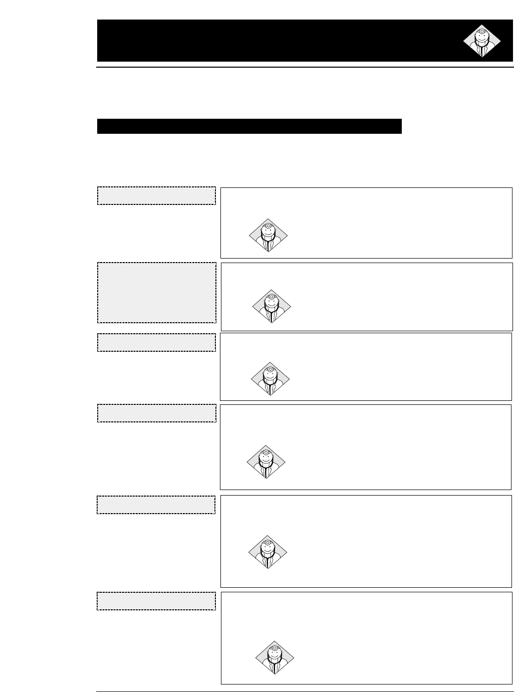
6.Troubleshooting
6-1
— 6. Troubleshooting —
When a funtional error occurs, the ERROR lamp blinks and
the buzzer sounds for five seconds. In this case, turn off the
power once and remove the cause of the error.
When the printer is used for continuous printing, its protective function may be
invoked to prevent malfunctions. If the printer does not recover from a functional
error, please contact the dealer.
Functional error messages (displayed on the LCD)
CARRIAGE ERROR
NO LCD DISPLAY
The error lamp blinks and the
buzzer sounds immediately
after turning the power on or
after the printer is reset.
FAN ERROR
CARRIAGE ERROR
• The print head is not in place.
Check whether the ribbon or paper was caught by the
print head. Recheck the paper thickness adjustment.
FAN ERROR
• The fan for cooling the internal circuits stopped.
Turn off the power, then turn it back on. If the printer
does not recover from the error, contact the dealer.
INTERNAL RAM ERROR
• An error occurred in the internal RAM.
Turn off the power and then turn it back on. If the print-
er does not recover from the error, contact the dealer.
F.S. ERROR
T.S. ERROR
F.S. ERROR
• An error occurred in the paper ejection mechanism.
Detach the rear cover, and check whether or not paper is jammed
in the paper ejection mechanism in the back of the printer.
Remove any paper, turn off the power, and turn it on again. If the
printer does not recover from the error, contact the dealer.
T.S. ERROR
• An error occurred in the paper path switching mechanism.
Remove all paper. Turn the power on and off several
times.
Turn off the power and then turn it back on. If the printer
does not recover from the error, contact the dealer.
HEAD ADJUSTMENT ERROR 1
• The print head was not adjusted to the standard position after head
adjustment motion.
Turn off the power and then turn it back on. If the
printer does not recover from the error, contact the
dealer.
HAI.S. ERROR
●
Error messages and countermeasures
6-2 — 6. Troubleshooting —
HOME S. ERROR
HEAD ADJUSTMENT ERROR 2
•Contact of the print head with the platen or paper when the print head
moved from the standard position toward the platen during head
adjustment was not confirmed.
Turn off the power then turn it back on. If the printer
does not recover from the error, contact the dealer.
HOME SENSE ERROR
• The home position cannot be detected properly when home sensing is
executed.
Check whether the ribbon or paper has been caught by
the print head. Recheck the paper thickness adjustment.
PLEASE POWER OFF ABNORMAL CURRENT ERROR
• An abnormal current was detected.
The printer is automatically turned off after five
seconds. Stop using the printer, and contact the dealer.
PARK ERROR PAPER PARK ERROR
•This error message indicates that fanfold paper is not being retracted
properly. The ERROR lamp blinks, the buzzer sounds three times,
and the printer enters the offline state.
Check whether paper is jammed in the paper ejection
mechanism. This error occurs when paper that cannot
be retracted though reverse feeding motion is printed
for approximately three pages. If three pages or more
have been printed, keep the REVERSE LF key depressed
to move back the paper.
HEAD PROTECTION PRINT HEAD COOLING
• The print head is being cooled to prevent it from overheating.
The ONLINE lamp blinks.
The print head has become too hot during high-density
printing. When this message is displayed, the printing
speed is reduced or printing stops. When the print head
temperature drops, the printer restarts printing.
HA.S. ERROR
Operational error messages (displayed on the LCD)
●
Error messages and countermeasures
6-3
— 6. Troubleshooting —
PAPER OUT: F.TR.
PAPER OUT: R. TR.
SET PAPER
PAPER OUT: CSF
Front Tractor
Rear Tractor
Manual
CSF
OUT-OF-PAPER ERROR
• This error message indicates that paper feeding has failed in the CSF
mode or that no paper is set in the fanfold paper or manual paper
loading mode. The ERROR lamp lights, the buzzer sounds for one
second, and the printer enters the offline state.
The ONLINE, PAPER PATH, EJECT/LOAD, FORM FEED, LINE
FEED and other keys are effective. Resetting is also effective.
ONLINE key
If there is still print data, paper is fed. If paper is fed properly,
the out-of-paper condition is reset and the printer enters the
online state. If paper is not fed properly, the printer remains in
the out-of-paper condition.
If there is no print data, the out-of-paper condition is
reset and the printer enters the online state.
PAPER PATH key
Press the PAPER PATH key to change the paper path.
The out-of-paper condition is reset and the printer
enters the online state.
EJECT/LOAD, FORM FEED and LINE FEED
keys
If paper is fed properly, the no-paper condition is reset
and the printer enters the previous (online or offline )
state.
If manual feeding is selected, paper is fed only
when the paper sensor detects paper. Paper is not fed
by pressing the key.
PAPER JAM : F.TR.
PAPER JAM : R.TR.
SET PAPER AGAIN
REMOVE PAPER
Front Tractor
Rear Tractor
When paper insertion has failed
When paper ejection has failed
PAPER JAM ERROR
• This error occurs when fanfold paper is not fed properly, manually-
loaded or CSF-loaded paper is not ejected properly, or paper is not
properly manually loaded from the front or rear. The ERROR lamp
lights, and the buzzer sounds three times.
The LINE FEED and REVERSE LF keys are effective.
Remove jammed paper using these keys or by hand.
The ONLINE key is also effective. When "PAPER JAM"
is displayed, pressing the ONLINE key will clear the
error status.
The paper jam sensor may not function properly if the
sensor is exposed to a direct light or sunlight.
●
Error messages and countermeasures
6-4 — 6. Troubleshooting —
PAPER IS SKEWED
•This error occurs if the printer detects that cut sheet paper was loaded
on the skew manually. The ERROR lamp blinks, and the buzzer
sounds three times. The paper is ejected and the printer enters the
offline state.
Load paper again. If it is loaded straight, the printer
enters the online state.
SKEW ERROR
COVER OPEN ERROR
•This error occurrs if the front cover is opened. The ERROR lamp
lights, and the ONLINE lamp blinks.
Closing the front cover will remove the cause of this
error. The printer is in the offline state while the cover
is opened.
FRONT COVER OPEN
PAPER PATH ERROR
•This error occurs in paper feeding if the cover that should be opened is
not open or the cover that should be closed is not closed. The ERROR
lamp lights, and the buzzer sounds three times, and the printer enters
the offline state.
The printer is recovered from this error and enters the
previous online or offline state by opening or closing the
cover, properly according to the message displayed on
the LCD.
OPEN TOP COVER
CLOSE REAR COVER
OPEN REAR COVER
OPEN PAPER RACK
Single Sheet Top Out
Single Sheet Top Out
Fanfold Top Out
Single Sheet or Rear Tractor
HEAD ADJUSTING ERROR
•This error occurs if the print head contacts the paper but cannot move
to the specified position after paper is loaded in the fixed paper
thickness mode. The ERROR lamp lights, and the buzzer sounds
three times, and the printer enters the offline state.
The current HEAD ADJUSTMENT setting is dispalyed
by pressing the SET UP key. Change the click position
with the or key and press the ENTER key to
move the print head to the currently set position. If the
print head moves properly, the printer will enter the
offline state. If the print head fails to move properly, the
error message reappears.
H.ADJ: FIX ERROR
PRESS SETUP
FIX: +10CLICK
These messages are
displayed alternately at 3
second interval.
●
Error messages and countermeasures
6-5
— 6. Troubleshooting —
JAM SENSOR ERROR
• The jam sensor was found defective when loading fanfold paper.
The ERROR lamp lights, and the buzzer sounds three times, and the
printer enters the offline state.
Press the ONLINE key to recover the printer from this
error. The paper jam detection function is disabled.
Remove paper dust from the jam sensor, and load
fanfold paper again.
FLAP SWITCHING ERROR
•This error occurs if the flap is not located at the proper position.
The ERROR lamp lights, and the buzzer sounds three times, and the
printer enters the offline state.
Any keys are ignored except the ONLINE key. When the
rear paper is removed and the ONLINE key is pressed,
the paper path is changed. When this operation is
completed properly, the printer enters the previous
online or offline state.
REMOVE REAR PAP.
JAM.S LEVEL ERR
PRESS ONLINE SW
These messages are
displayed alternately at 3
second interval.
*1) When the head adjustment is not appropriate,
(1) In the AUTO mode:
Specify the appropriate head adjustment again in the range from -2 to +5. When the appropriate
head adjustment cannot be set, carry out this setting in the FIX mode.
(2) In the FIX mode:
Specify the appropriate head adjustment again.
(3) When the appropriate head adjustment cannot be specified, the head adjustment mechanism is
faulty. Have it replaced by the dealer.
6-6 — 6. Troubleshooting —
●
Troubleshooting
Cause and Solution
• Power cord not connected.
• Malfunction of the power supply in the
printer
Contact the dealer.
• The paper sensor is clogged by paper dust.
Clean the paper sensor.
• Malfunction of the paper sensor
Contact the dealer.
• The print head has overheated.
Wait until it has cooled down.
• Head adjustment is not set correctly. (*1)
• The print head may need to be replaced.
• Ribbon cassette may need to be replaced.
• Head adjustment is not set correctly. (*1)
• Ribbon cassette is not properly installed.
• The print head may need to be replaced.
• Check whether the cable connection is faulty
or broken.
• Host system control and data code may not
match the printer's setup.
• Check the emulation setting of the EXTENDED
SETUP MODE.
• Adjust with the vertical alignment function.
• The print head may need to be replaced.
• Stack of fanfold paper to be fed is placed
beside the printer crookedly.
• The automatic carriage return option in the
extended setup options is set incorrectly.
• Change the setting of #27 CR SETTING on
the EXTENDED SETUP MODE.
Symptoms
POWER lamp fails to
light.
Error lamp does not
light.(Out-of-paper
error not detected.)
Printer stops or slows
down on printing.
Poor quality printing
Smudging of the paper
Incorrect character
printed
Print position gap
occurs over bar code
or vertical line.
Fanfold paper slips
Extra line feed
See page 1-1.
See page 3-9.
See page 6-3.
See page 3-9.
See page 4-6.
See page 1-12.
See page 3-27.
See page 6-3.
See page 1-2.
●
Troubleshooting
6-7
— 6. Troubleshooting —
Cause and Solution
• Paper is curled. Carefully remove the jammed
paper.
• Head adjustment is not set correctly. (*1)
• Push down the lock lever of tractors to the
LOCK position.
• When using the printer in an environment
where it is exposed to a direct light or
sunlight, make sure that the paper jam sensor
is not directly exposed to the light.
• There is some obstruction in the paper path or
ejection path.
• The paper jam sensor is clogged by paper
dust. Clean the paper jam sensor. (*2)
• Malfunction of the paper jam sensor
Contact the dealer.
• Paper jam detection is set to NO in the
EXTENDED SETUP MODE. Change the
setting of #65 PAPER JAM DETECTION.
• The skew sensor is clogged by paper dust.
Clean the skew sensor. (*2)
• Malfunction of the skew sensor
Contact the dealer.
• Skew detection is set to NO in the
EXTENDED SETUP MODE. Change the
setting of #64 SKEW DETECTION.
• Turn the power on and off several times.
• Malfunction of the flap mechanism
Contact the dealer.
• Turn the power on and off several times.
• Malfunction of the tractor mechanism
Contact the dealer.
• The paper ejection path is not set properly.
Set the proper ejection path using the PAPER
PATH key or #61 PAPER PATH on the
EXTENDED SETUP MODE.
• Upward ejection cannot be used when paper
that has a short page length (150 mm or less)
is being used.
Symptoms
Paper jam
Paper jam is not
detected.
Paper is skewed.
Skewing is not
detected.
Flap will not change
Tractor mode cannot
be changed
Paper is not ejected
to the top.
See page xiii.
See page 3-44.
See page 6-1.
See page 6-1.
See page 3-42.
See page 3-43.
*2) How to clean the paper jam sensor and skew sensor cover
After switching the power off, remove the ink ribbon and clean these sensors using a vacuum
cleaner or cotton-swab.
See page xiii.
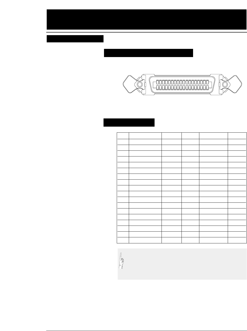
7. Interface specifications
7-1
— 7. Interface specifications —
Bidirectional (IEEE1284. Nibble mode) is available.
Parallel interface
PIN SIGNAL IN/OUT PIN SIGNAL IN/OUT
1 STROBE * IN 19 GND
2 DATA 1 IN 20 GND
3 DATA 2 IN 21 GND
4 DATA 3 IN 22 GND
5 DATA 4 IN 23 GND
6 DATA 5 IN 24 GND
7 DATA 6 IN 25 GND
8 DATA 7 IN 26 GND
9 DATA 8 IN 27 GND
10 ACK * OUT 28 GND
11 BUSY OUT 29 GND
12 PE OUT 30 GND
13 SELECT OUT 31 INITIAL * IN
14 AUTO FEED * IN 32 ERROR * OUT
15 NC 33 GND
16 GND 34 NC
17 GHASSIS GND 35 HIGH OUT
18 +5V OUT 36 SELECT IN * IN
(1) The signals marked with asterisks are negative logic signals.
(2) The High level is raised to +5 V with a 2.2 kΩresistor.
(3) NC means "not connected".
(4) The CHASSIS GND and GND are connected inside the
printer.
Pin configuration
Input connector (36-pin parallel )
18 1416 12 10 8 6 4 217 1315 11 9 7 5 3 1
36 3234 30 28 26 24 22 2035 3133 29 27 25 23 21 19
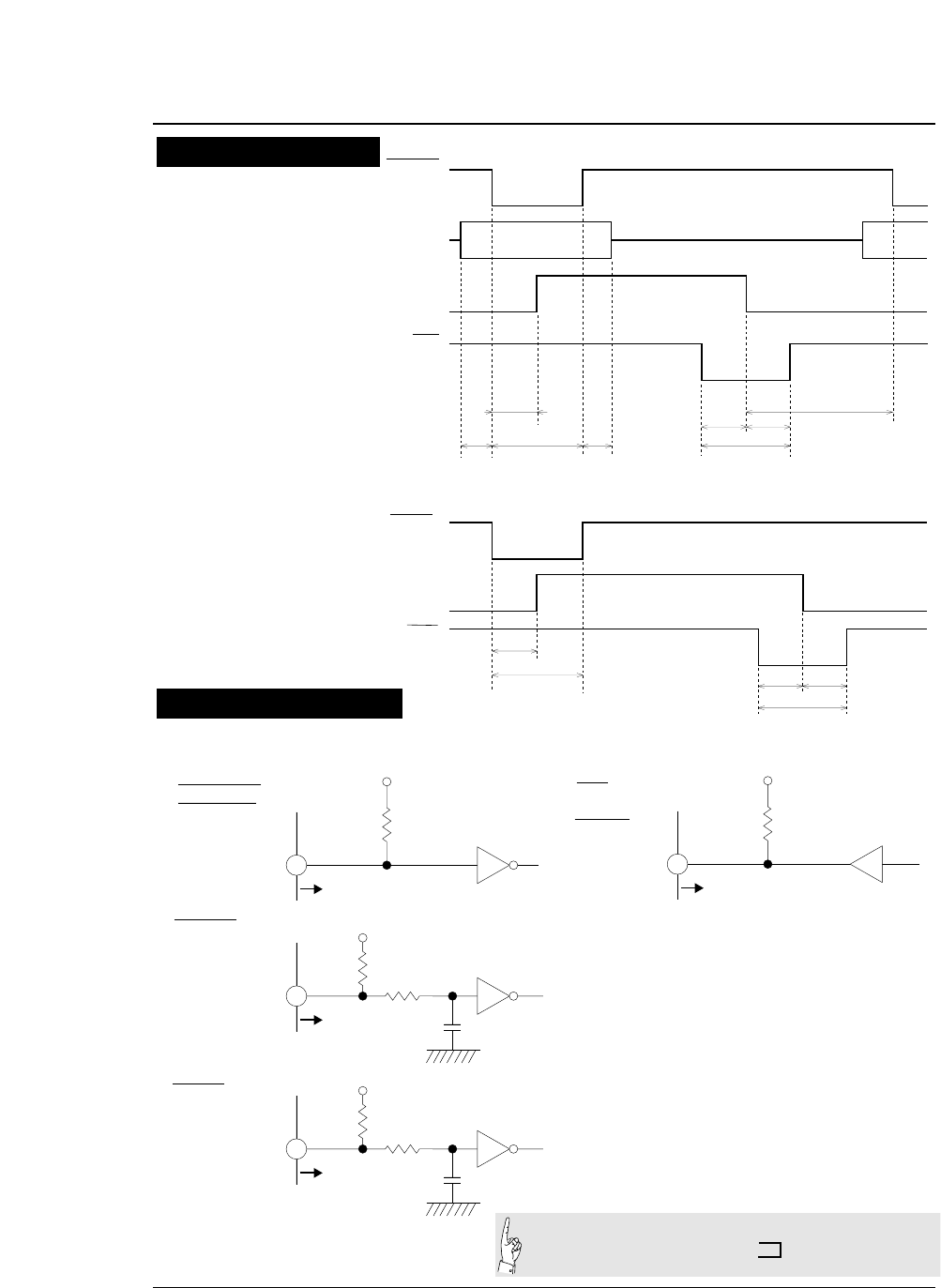
●Parallel interface
7-2 — 7. Interface specifications —
1~50µs1µs
(MIN) 1µs
(MIN) 7~10µs
4~6µs 4~6µs
ATA 1~8
BUSY
TROBE
ACK
0µs
(MIN)
1µs
(MAX)
INITIAL
BUSY
ACK 50µs
(MAX)
50µs(MIN) 4~6µs
7~10µs
4~6µs
Data Input
Initialization
Timing chart
+5V
2.2K Ω
To printer (74LS04
or equivalent)
Input Terminal
• DATA1 ~ DATA8
• AUTO FEED
• SELECT IN
+5V
To printer
100 Ω
330pF
(74LS14
or equivalent)
• STROBE
2.2K Ω
• INITIAL +5V
To printer
100 Ω
1000pF
(74LS14
or equivalent)
2.2K Ω
All signals are TTL-level signals.
HIGH LEVEL 2.4 ~ 5.0 V
LOW LEVEL 0 ~ 0.4 V
At the input terminals
of the printer
Input Terminal
Input Terminal
+5V
2.2K Ω
To printer (7406,7407
or equivalent)
Output
Terminal
• BUSY
• ACK
• PE
• ERROR
• SELECT
Input/output conditions
Input Signals Output Signals
●Parallel interface
[DATA1 to DATA8]
Each of these signals is an 8-bit data signal. It is high
when the signal is logic 1 and low when the signal is
logic 0. DATA1 is the LSB, and DATA8 is the MSB.
[STROBE]
This is a strobe signal for reading an 8-bit data signal.
Data is read in at the falling or rising edge of the
STROBE signal.
[INITIAL]
This signal initializes the printer to the state in which the
printer starts up when the power is turned on. It is
normally high. When it is set to low, the printer is reset.
When it is set to high again, the printer is initialized.
[AUTO FEED]
If this signal is set to low when #27 CR SETTING is set
to AUTOFEED in the EXTENDED SETUP MODE, line
feeding is performed when the CR command is executed.
In the HP mode or IBM mode, it is possible to specify
whether to perform line feeding after executing the CR
command by using the software command, regardless of
the settings of this signal and #27 CR SETTING in the
EXTENDED SETUP MODE.
[SELECT IN]
When this signal is set to high, the control code is
validated. Validity of this signal is specified in the
extended setup mode. In the HP mode, this signal setting
is ignored.
7-3
— 7. Interface specifications —
Signal explanations
Input signals to the printer
See page 3-53.
See page 3-29.
See page 3-53.
See page 3-47.
Each signal wire must be 2 meters or less in
length. It is recommended that a twisted pair
of signal and GND wires be used.
[BUSY]
This signal indicates that the printer is in the busy state.
While it is high, no external data is accepted.
This signal is set to high in any of the following cases:
(1) Initialization is being performed.
(2) The STROBE signal is issued and data is input.
(3) The self-test printing is being performed.
(4) The printer is in the offline state.
(5) The printer cover is open.
(6) The printer is in an error state.
[ACK]This signal is output at the falling edge of the BUSY
signal which was set high by the STROBE signal. No
ACK signal is output in cases (4), (5), (6) above.
[PE] This signal is set high when no paper is detected. It is set
low when paper is detected.
[ERROR]
This signal is set low when an out-of-paper error or other
error occurs in the IBM mode.
It is set low when printer is in the offline state, in
addition to the errors noted above, in the EPSON mode.
This signal is set low when the functional error occurs in
the HP mode.
[SELECT]
This signal is always set high in the EPSON mode.
In the IBM mode, it is set low when an out-of-paper
error, paper error or functional error occurs, the printer
cover is opened, the printer is in the offline state, or the
deselect command (ESC + Q + (23)H or (B9)H) is
executed. It is set high when the printer is in the online
state with the ONLINE key or the DC1 (select) command
is executed.
In the HP mode, this signal is set low when the printer is
in the offline state. It is set high when the printer is in
the online state.
●Parallel interface
7-4 — 7. Interface specifications —
Output signals from
the printer
See page 3-53.
See page 6-3.
When #84 ERROR STATUS is set to NO in the
EXTENDED SETUP MODE, PE signal is always set to low
and ERROR and SELECT signals are always set to high.
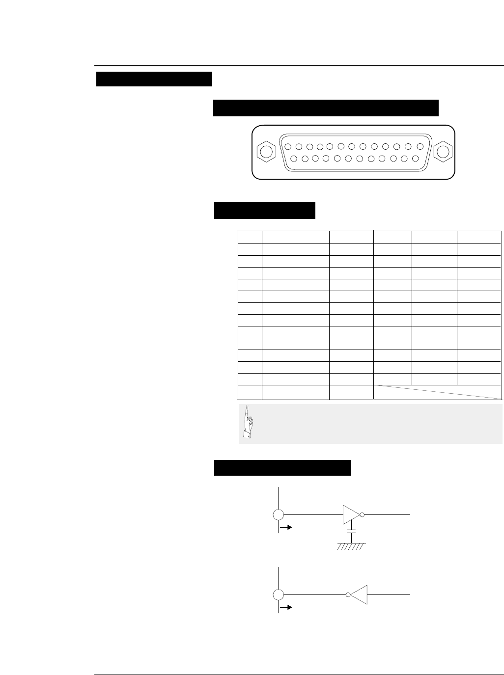
●Serial interface
7-5
— 7. Interface specifications —
Serial interface
Pin configuration
Input connector (25-pin serial connector)
13245678910111213
15 1416171819202122232425
PIN SIGNAL IN/OUT PIN SIGNAL IN/OUT
1 CHASSIS GND 14 NC
2 TXD OUT 15 NC
3 RXD IN 16 NC
4 RTS OUT 17 NC
5 CTS IN 18 NC
6 DSR IN 19 NC
7 SIGNAL GND 20 DTR OUT
8CD IN21NC
9NC 22NC
10 NC 23 NC
11 SRTS OUT 24 NC
12 NC 25 NC
13 NC
To printer
INPUT
330pF
(75189 or equivalent)
To printer
OUTPUT (75188 or equivalent)
Signal levels
OFF: Indicates "MARK" at a level from -3 to -15 V.
ON: Indicates "SPACE" at a level from +3 to +15 V.
Input signal
Output signal
Input/output conditions
(1) NC means "not connected".
(2) The CHASSIS GND and SIGNAL GND are connected inside
the printer.
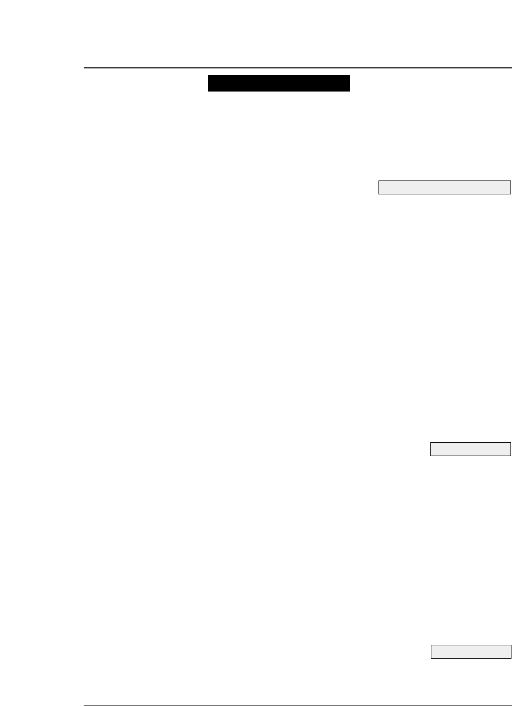
[RXD (Receive data)]
Serial input data, which consists of a start bit, data bits,
(parity bit), and stop bit.
The data length (7 or 8 bits), use of the parity bit, and
even or odd parity are specified in the EXTENDED
SETUP MODE.
[CTS (Clear to send)]
A data transmission control signal, which indicates that
data can be sent to the computer.
Whether or not to use this signal to control data
transmission is specified in the setup mode. This signal
is not used by default.
If the X-ON/X-OFF or ETX/ACK protocol is selected
and the CTS ENABLE option is set to NO in the
EXTENDED SETUP MODE, the printer outputs data to the
computer, regardless of this signal setting.
If the X-ON/X-OFF or ETX/ACK protocol is selected
and the CTS ENABLE option is set to YES in the
EXTENDED SETUP MODE, the printer outputs data to the
computer according to this signal setting.
[DSR (Data set ready)]
This signal indicates the state of the modem or computer.
If data is sent to the printer when this signal is ON, the
data is processed as valid data.
Data received when this signal is OFF is ignored as
invalid data.
By default, this signal is not used, and all data sent by the
computer is processed as valid data (i.e., the default
setting causes the same operation as when the DSR
signal is ON). Whether or not to use this signal for
control is selected in the EXTENDED SETUP MODE.
●Serial interface
7-6 — 7. Interface specifications —
See pages 3-47 and 3-48.
See page 3-50.
See page 3-51.
Input signals to the printer
●Serial interface
[CD (Carrier detect)]
This signal indicates whether the modem is connected
with the communication line. If data is sent to the printer
when this signal is active, the data is processed as valid
data. Data received when this signal is inactive is
ignored as invalid data.
By default, this signal is not used, and all data sent by the
computer is processed as valid data (i.e., the default
setting causes the same operation as when the CD signal
is active). Whether or not to use this signal for control is
selected in the EXTENDED SETUP MODE.
[TXD (Transmit data)]
Serial output data.
X-ON, X-OFF and ACK signals are output.
The data format is the same as the received data format.
[RTS (Request to send)]
Always held active (space).
[SRTS]
This signal indicates that the printer is ready or busy.
OFF : Indicates that the printer is busy and printer is in
the offline state. Data transmission to the printer is
disabled.
ON : Indicates that the printer is ready and data can be
transmitted to the printer.
This signal is always ON when X-ON/X-OFF( Ι )or( Π )or
the ETX/ACK protocol is selected.
[DTR (Data terminal ready)]
This signal indicates that the printer is ready or busy.
OFF: Indicates that the printer is busy and printer is in the
offline state. Data transmission to the printer is
disabled.
ON: Indicates that the printer is ready and data can be
transmitted to the printer.
This signal is always ON when X-ON/X-OFF (I) or (II) or
the ETX/ACK protocol is selected.
7-7
— 7. Interface specifications —
See page 3-51.
Output signals from the printer
Any of four handshaking protocols is selected in the
extended setup mode.
- DTR protocol
- X-ON/X-OFF (I) protocol
- X-ON/X-OFF (II) protocol
- ETX/ACK protocol
Control of these serial protocols is based on the free area in the data
buffer. There are two protocol control points based on the data buffer:
CIN, where the ready state changes to the busy state, and CRN, where
the busy state changes to the ready state. The values of these points are
shown below.
When 512KB or 8KB buffer size is selected,
CIN: 1KB
CRN: 2KB
When 128-byte buffer size is selected,
CIN: 32 bytes
CRN: 64 bytes
When the free space in the data buffer is reduced below the CIN value,
the printer enter the busy state and remains there until the free space
exceeds the CRN value. When the free space exceeds the CRN value,
the printer enters the ready state.
In this protocol, the printer state is indicated by the SRTS signal
(pin No. 11) and DTR signal (pin No. 20).
When the printer is ready, each signal goes ON (+12 V). When
the printer is busy or in the offline state, each signal goes OFF
(-12 V).
When the printer is busy or in the offline state, the computer does
not send data.
However, data from the computer can be received when the
printer is busy or in the offline state.
(1) When the power is turned on,
The SRTS and DTR signals go ready when data input is
enabled on completion of initialization after turning on
the power.
●Serial interface
7-8 — 7. Interface specifications —
Handshaking protocol
See page 3-49.
DTR (READY/BUSY) Protocol

●Serial interface
In this protocol, the printer sends the X-ON(11)H and X-
OFF(13)H codes to the computer to indicate the printer state.
In the X-ON/X-OFF protocol, the printer sends X-OFF(13)H to
the computer once when the ready state changes to the busy or
offline state, once when 64 bytes of data have been received
since this point in time, and once when the free area in the buffer
becomes zero.
The printer sends X-ON(11)H once to the computer when the
busy or offline state changes to the ready state or the power is
turned on. If the ONLINE key is pressed in the offline state and
the free space in the buffer is greater than the CIN value, the
printer sends X-ON and enters the ready state. If the free space
in the buffer is less than the CIN value, the printer enters the busy
state without any operation. In the busy or offline state, the
SRTS and DTR signals remain active. X-ON and X-OFF signals
are sent to the computer even if the DSR or CD input signal is
inactive. In the X-ON/X-OFF (I) protocol, the X-ON signal is
sent when the power is turned on. In the X-ON/X-OFF (II)
protocol, the X-ON signal is not sent when the power is turned
on.
The X-OFF signal is sent once in any of the following conditions:
(1) The ready state changes to the busy state.
(2) The ready state changes to the offline state.
(3) 64 bytes of data are received in the state shown in (1) or
(2) above, provided the free area in the buffer is greater
than 64 bytes.
(4) The free area in the buffer becomes zero, regardless of the
online or offline state.
The X-ON signal is sent once in any of the following conditions:
(1) The busy state changes into the ready state.
(2) The offline state changes into the online state.
(3) The printer enters the online state when power is turned
on, provided the X-ON/X-OFF (I) protocol is selected.
7-9
— 7. Interface specifications —
X-ON/X-OFF (I)/(II) protocol
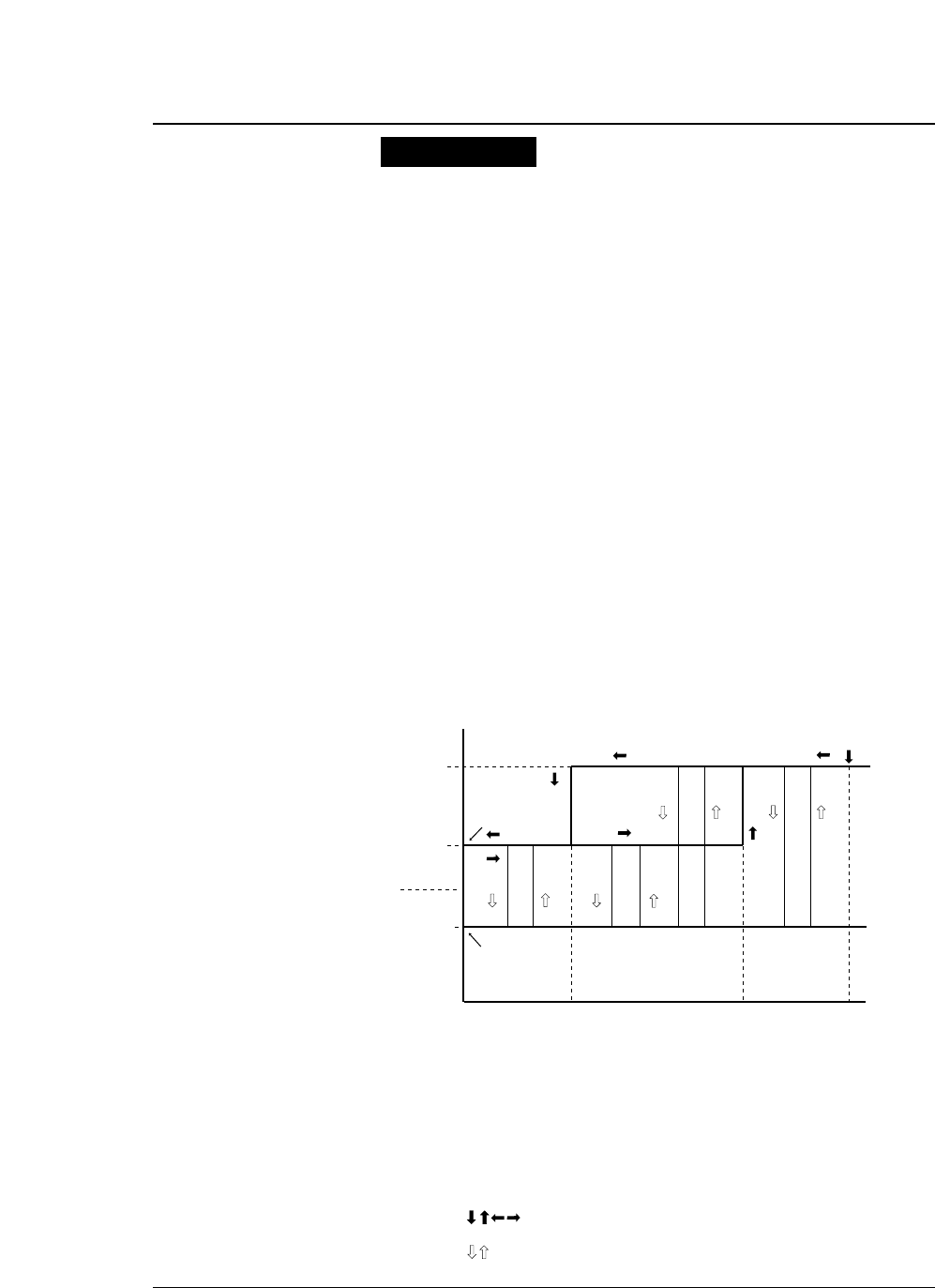
(1) If the ONLINE key is pressed in the offline state and the
free area in the buffer is over the CIN value,
1) The printer sends X-ON and enters the online ready
state if it was in the ready state.
2) The printer sends no signal and enters the online busy
state if it was in the busy state.
(2) If the ONLINE key is pressed in the offline state and the
free area in the buffer is less than the CIN value, the printer
sends no signal and enters the online busy state.
(3) If the ready state is changed into the offline state by pressing
the ONLINE key and data is input and the free area in the
buffer exceeds the CIN value during data input even though
the printer has sent X-OFF once, the printer does not send
X-OFF.
However, if the printer receives the 64th byte of data after
entering the offline state, it sends X-OFF once.
(4) The printer sends X-OFF once if the printer enters the
offline state due to an out-of-paper error after initialization.
(5) In the X-ON/X-OFF (I) protocol, X-ON is output after
power on when initialization is completed and the printer
enters the online state.
●Serial interface
7-10 — 7. Interface specifications —
Special notes
READY
ON-LINE
BUSY
OFF-LINE
POWER ON
0 CIN CRN FULL
[OFF]
(OFF) (OFF)
(ON) (ON)
[ON]
<OFF>
<OFF>
{OFF}
(X) (X) (X)(X)
<ON>
<ON>
: X-ON or X-OFF is sent once when the data size
changes.
: X-ON or X-OFF is sent once when the ONLINE
key is pressed.
: X-OFF is sent when the 64th byte of data is
received after sending X-OFF.
: X-OFF is sent when the free area in the buffer
becomes zero.
: X-ON is sent when power is turned on and the
X-ON/X-OFF (I) protocol is in use.
: No signal is sent. Status transition due to change
in the amount of data.
: Status transition caused by pressing the ONLINE key.
[ON][OFF]
(ON), (OFF)
{OFF}
<OFF>
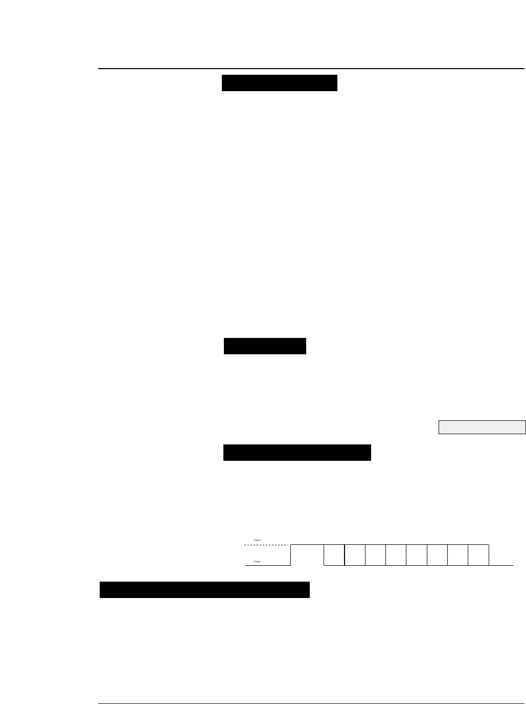
●Serial interface
Upon reception of ETX(03)H, the printer sends ACK(06)H to the
computer to indicate that it is ready. If the printer is busy, it does
not send ACK to indicate that it is busy.
If the free area in the buffer is less than the CIN value when the
printer receives ETX, the printer does not send ACK
immediately. It sends ACK when the free area in the buffer
becomes greater than the CRN value. If the printer is in the
offline state, the printer sends ACK when the ONLINE key is
pressed and the printer becomes ready.
In the busy or offline state, the SRTS and DTR signals remain
ON. The printer sends ACK to the computer even if the CTS
input signal is OFF.
The interface does not analyze the (03)H code. Thus, the printer
sends ACK in response to (03)H received in an escape sequence
or graphic data sequence. The received (03)H code is sent to the
emulation as normal data.
The baud rate can be selected from the values shown below in the
extended setup mode:
38400BPS, 19200BPS, 9600BPS, 4800BPS,
24
00BPS,
12
00BPS,
6
00BPS,
3
00BPS,
The data frame has the following organization.
START BIT (1) + DATA BIT
(7 or 8)
+ PARITY BIT
(0 or 1)
+ STOP
BIT (1 or 2) MARK: Logic "1" (-3 to -15 V)
SPACE: Logic "0" (+3 to +15 V)
7-11
— 7. Interface specifications —
ETX/ACK protocol
Baud rate
Serial data organization
Automatic serial/parallel selection
+3 +15V
-3 -15V START D1 D2 D3 D4 D5 D6 D7 D8 STOP
See page 3-49.
If #70 INTERFACE is set to AUTO in the EXTENDED SETUP MODE, the serial or parallel
interface is selected automatically.
In the initial condition, both the serial and parallel interfaces are ready. When data is input
through either interface, printing is done through that interface. In printing, the other interface is
in the busy state. If data is input through the busy interface, the data is ignored.
If no data is input to the first interface, both interfaces are reset to the initial ready state.
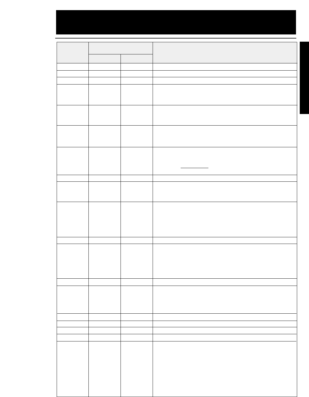
8-1
— 8. Software commands —
BEL (07)D (07)H
Activates the printer buzzer.
BS (08)D (08)H
Moves the printing position leftward by one character.
HT (09)D (09)H
Moves the printing position to the next horizontal tab.
LF (10)D (0A)H
Single line feed
Causes a carriage return if #28
LF SETTING is set to CR + LF
in
the EXTENDED SETUP MODE.
VT (11)D (0B)H
Vertical tab
Causes a carriage return if #28 LF SETTING is set to CR + LF in
the EXTENDED SETUP MODE.
FF (12)D (0C)H
Form feed
Causes a carriage return, regardless of the setting in the
EXTENDED SETUP MODE.
CR (13)D (0D)H
Carriage return
Executes a line feed after a carriage return if #27 CR SETTING
is set to CR + LF or #27 CR SETTING is set to AUTOFEED and
the parallel AUTO FEED signal is low.
SO (14)D (0E)H
Double-width printing on a single line.
SI (15)D (0F)H
Specifies condensed mode (from 10 cpi to 17 cpi, 12 cpi to 20 cpi, or
proportional to condensed proportional). Valid only when #34
PITCH LOCK is set to NO in the EXTENDED SETUP MODE.
DC1 (17)D (11)H
Printer select
Cancels the input data ignoring condition which is set by the DC3
(deselect) code. Valid when #71 SELECT IN ENABLE is set to 1
in the EXTENDED SETUP MODE or SELECT IN ENABLE is
selected to I/F and the SELECT IN signal is high.
DC2 (18)D (12)H
Cancels condensed mode.
DC3 (19)D (13)H
Printer deselect
Puts the printer into the deselect state. Valid when #71 SELECT
IN ENABLE is set to 1 in the EXTENDED SETUP MODE or
SELECT IN ENABLE is selected to I/F and the SELECT IN
signal is high.
DC4 (20)D (14)H
Cancels the double-width mode established by the SO command.
CAN (24)D (18)H
Cancel
Clears all data in the print buffer and printing position specified
with the horizontal position move command (HT, ESC $, ESC \,
etc.).
DEL (127)D (7F)H
Deletes a character.
ESC (27)D (1B)H
Designates ESC sequence.
ESC SO (27)D(14)D (1B)H (0E)H
Double-width printing on a single line.
ESC SI (27)D(15)D (1B)H (0F)H
Specifies condensed mode.
ESC EM (27)D(25)D (1B)H (19)H
Specifies the paper path.
nn n
n="R" : Ejects paper.
n="B" : Feeds paper with the rear tractor.
n="F" : Feeds paper with the front tractor.
n="M" : Feeds manually loaded paper.
n="f" : Ejects paper to the front.
n="t" : Ejects paper to the top.
n="r" : Ejects paper to the rear.
Decimal Hex
Symbol Function
Code
EPSON Software commands
8. Software commands
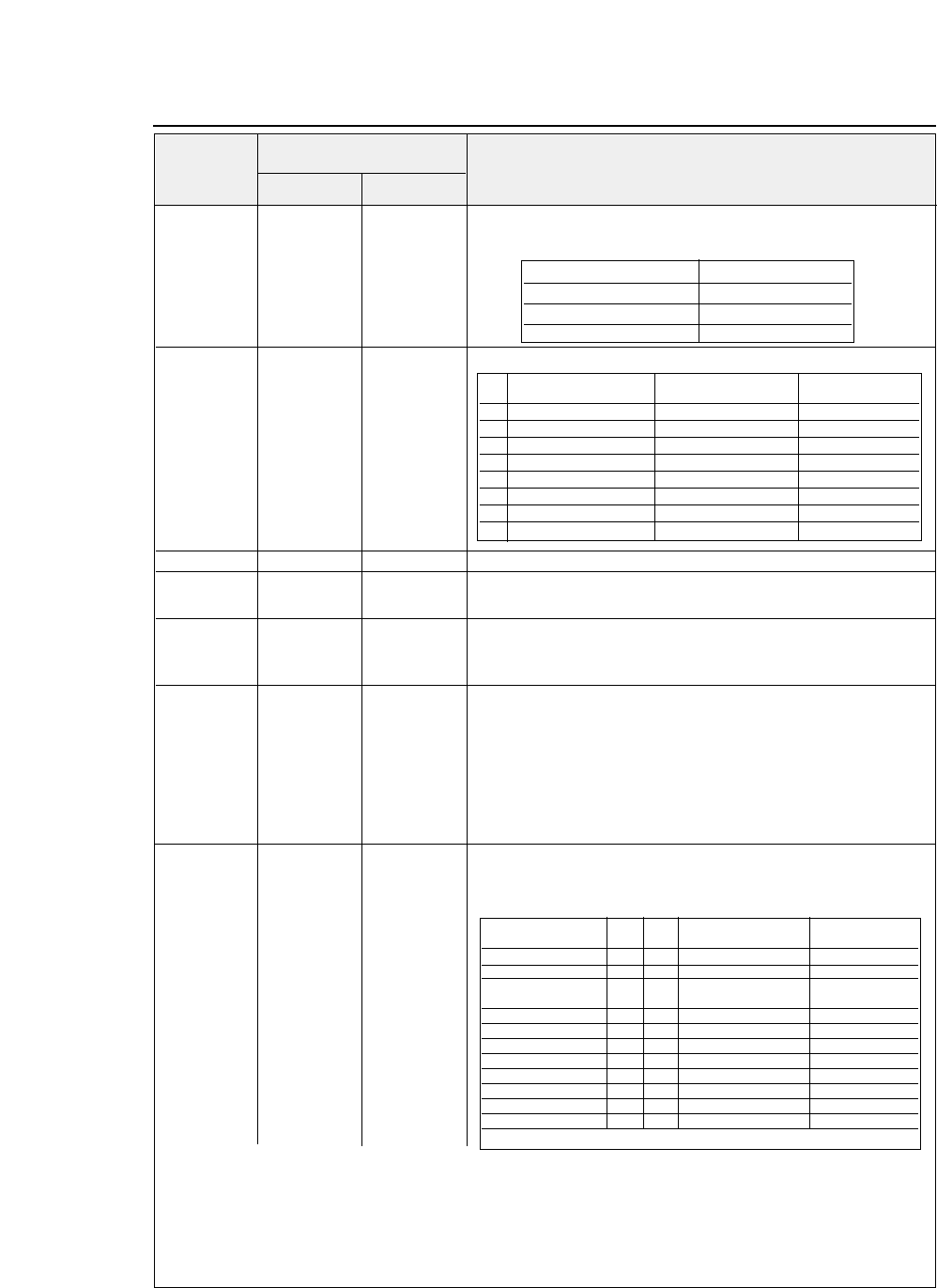
ESC SP (27)D(32)D (1B)H (20)H
Specifies the space between characters.
(0 ≤n ≤127)
nn n
The dot density differs with the printing mode, as shown below.
ESC ! (27)D(33)D (1B)H (21)H
Batch selection of the printing mode
(0 ≤n ≤255)
nn n
ESC # (27)D(35)D (1B)H (23)H
Cancels MSB control.
ESC $ (27)D(36)D (1B)H (24)H
Specifies the absolute printing position.
n1 n2 n1 n2 n1 n2
Distance =
n1 + ( n2
×
256 )
(In units of 1/60 inch)
ESC % (27)D(37)D (1B)H (25)H
Specifies or cancels the down-load character set.
(n = 00, 01, 30, 31)
nn n n = 01, 31:
Specifies the down-load character set.
n = 00, 30:
Cancels the down-load character set.
ESC & (27)D(38)D (1B)H (26)H
Defines the down-load characters.
s, n, m, s, n, m, s, n, m, s:
Down-load character set number
[ a0, a1, [ a0, a1, [ a0, a1, n :
Define start of ASCII code
(00)H ~ (7F)H
a2, data] a2, data] a2, data] m :
Define end of ASCII code
(00)H ~ (7F)H
m-n+1 m-n+1 m-n+1 a0 :
Left space
a1 :
Actual character width (Number of dots)
a2 :
Right space
ESC * (27)D(42)D (1B)H (2A)H
Selects graphic function.
mm m
8-pin graphic:
n1 +(n2
×
256)
n1 n2 n1 n2 n1 n2
24-pin graphic:
(n1 +(n2
×
256))
×
3
d1 d2 d1 d2 d1 d2
•••dk ••• dk ••• dk
In the 8-pin graphic mode, one bit of data corresponds to two print head pin dots, as shown below.
●
EPSON Software commands
Decimal Hex
Symbol Function
Code
8-2 — 8. Software commands —
Printing mode Dot pitch
Draft 1/120 inch
LQ 1/180 inch
Proportional 1/180 inch
Bit "1" "0" Command having
same function
0 12 cpi 10 cpi ESC M / ESC P
1 Proportional Proportional canceled ESC p
2 Condensed Condensed canceled SI / DC2
3 Emphasized Emphasized canceled ESC E / ESC F
4 Double strike Double strike canceled ESC G / ESC H
5 Double-width Double-width canceled ESC W
6 Italic Italic canceled ESC 4 / ESC 5
7 Underscoring selected Underscoring canceled ESC -
Mode Pin m Horizontal dot density Max. dots per line
(dot/inch)
Single-density 8 0 60 816
Double-density 8 1 120 1632
Double-speed 8 2 120 1632
double-density❈
Quadruple-density ❈8 3 240 3264
CRT I 8 4 80 1080
CRT II 8 6 90 1224
Single-density 24 32 60 816
Double-density 24 33 120 1632
CRT III 24 38 90 1224
Triple-density 24 39 180 2488
Hex-density❈24 40 360 4896
❈Horizontally adjacent dots can not be printed.
Data MSB ●●●●●●●●●●●●●●●●LSB
↓↓↓↓↓↓↓↓
Print head pin Top ●●●●●●●●●●●●●●●●●●●●●●●●●●●●●●●●●●●●●●●●Bottom
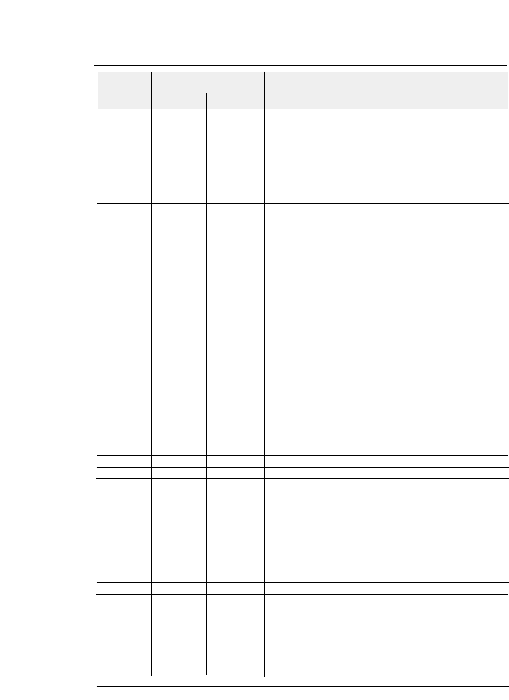
ESC ( - (27,40,45)D (1B,28,2D)H
Specifies line type.
( n1 = 3 ) ( n2 = 0 ) ( m = 1 )
n1 n2 n1 n2 n1 n2 d1 = 1
Underscore
d2 = 1
Single line
m m m d1 = 2
Center line
d2 = 2
Double lines
d1 d2 d1 d2 d1 d2 d1 = 3
Upper line
d2 = 5
Single dotted line
d2 = 6
Double dotted lines
d2 = 0
Cancels the line specification.
ESC ( ^ (27,40,94)D (1B,28,5E)H
All-character set.
n1 n2 n1 n2 n1 n2
Prints
n1 + n2 x 256 c
haracters in the all-character character set.
ESC ( t (27,40,116)D (1B,28,74)H
Specifies a character set.
n1n2 n1 n2 n1 n2 d1 :
Displays
ESC t n
command table No.
d1 d2 d1 d2 d1 d2 d2, d3 :
Specifies the character set.
d3 d3 d3 d2 = 0, d3=0 : ITALIC
d2 = 1, d3=0 : PC-437
d2 = 3, d3=0 : PC-850
d2 = 7, d3=0 : PC-860
d2 = 8, d3=0 : PC-863
d2 = 9, d3=0 : PC-865
d2 = 11, d3=0 : PC-857
d2 = 44, d3=0 : PC-858
d2 = 24, d3=0 : PC-861
d2 = 25, d3=0 : PC-BRASCII
d2 = 26, d3=0 : PC-ABICOMP
d2 = 17, d3=0 : ISO-8859-1
ESC + (27)D(43)D (1B)H (2B)H
Specifies a line feed pitch of n/360 inch.
(0 ≤n ≤255)
nn n
ESC - (27)D(45)D (1B)H (2D)H
Specifies or cancels underscoring.
n n n n = 01, 31:
Specifies underscoring.
n = 00, 30
: Cancels underscoring.
ESC / (27)D(47)D (1B)H (2F)H
Selects the vertical tab channel.
(0 ≤n ≤7)
mm m
ESC 0 (27)D(48)D (1B)H (30)H
Specifies 1/8 inch line feed pitch.
ESC 2 (27)D(50)D (1B)H (32)H
Specifies 1/6 inch line feed pitch.
ESC 3 (27)D(51)D (1B)H (33)H
Specifies line feed pitch of n/180 inch.
(0 ≤n ≤255)
nn n
ESC 4 (27)D(52)D (1B)H (34)H
Specifies the italic font.
ESC 5 (27)D(53)D (1B)H (35)H
Cancels the italic font.
ESC 6 (27)D(54)D (1B)H (36)H
Expands the character code area.
Makes the area from (80)H to (9F)H the character code area,
rather than the control code area, when the graphic character
table or down-load character table is selected. This is the initial
condition.
ESC 7 (27)D(55)D (1B)H (37)H
Cancels the expanded character code area.
ESC : (27)D(58)D (1B)H (3A)H
Copies the internal character set.
(0 ≤n ≤255)
NUL NUL NUL
Draft mode:
n = 0
n s n s n s
LQ mode:
n = 0 ~ 9
s :
Down-load character set number (See
ESC &)
ESC < (27)D(60)D (1B)H (3C)H
Returns to the home position.
Move the print head to the left end without sensing the home
position.
●
EPSON Software commands
Decimal Hex
Symbol Function
Code
8-3
— 8. Software commands —
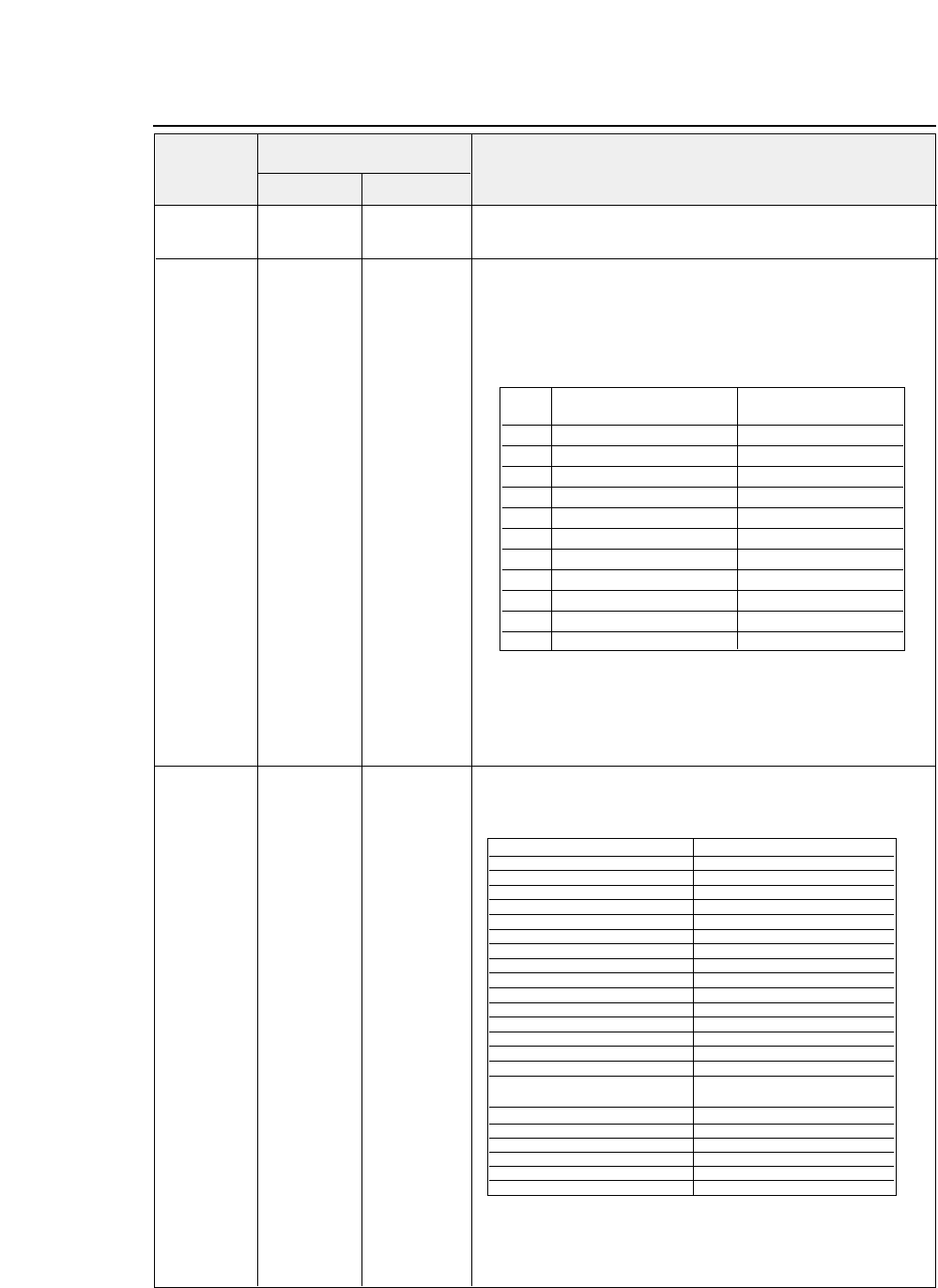
ESC = (27)D(61)D (1B)H (3D)H
Specifies
MSB 0
ESC > (27)D(62)D (1B)H (3E)H
Specifies
MSB 1
ESC ? (27)D(63)D (1B)H (3F)H
Converts the graphic modes.
n m n m
n m (n= "K","L","Y","Z", m = 0 ≤m ≤40)
Converts the
ESC K, ESC L, ESC Y or ESC Z
graphic mode
into the ESC * graphic mode.
n:
Graphic mode to be converted
m:
New graphic mode
The initial setting is as shown below;
ESC K = ESC
✽
00
ESC L = ESC
✽
01
ESC Y = ESC
✽
02
ESC Z = ESC
✽
03
ESC @ (27)D(64)D (1B)H (40)H
Initializes the printer.
Resets the print modes and clears command settings, data in the
print buffer and printing position.
●
EPSON Software commands
Decimal Hex
Symbol Function
Code
8-4 — 8. Software commands —
m Graphic mode Horizontal dot density
dpi (dot/inch)
0 Single-density 60 (8PIN)
1 Double-density 120 (8PIN)
2Double-speed double-density 120 (8PIN)
3 Quadruple-density 240 (8PIN)
4 CRT I 80 (8PIN)
6 CRT II 90 (8PIN)
32 Single-density 60 (24PIN)
33 Double-density 120 (24PIN)
38 CRT III 90 (24PIN)
39 Triple-density 180 (24PIN)
40 Hex-density 360 (24PIN)
Initialization item Status
•Line feed pitch Specified in setup mode
•Page length Specified in setup mode
•TOF Regarding current line as TOF
•Bottom margin Specified in setup mode
•Vertical tab Setting when power is turned on
•Vertical tab channel Channel 0
•Right & left margins Specified in setup mode
•Horizontal tab Specified in setup mode
•Inter-character pitch 0
•Character pitch Specified in setup mode
•Special effect Canceled
•Down-load character Not cleared
•Character set Specified in setup mode
•Single-direction printing Specified in setup mode
•MSB control Canceled
•According to ESC ?
Graphic mode conversion Canceled
•Justification Canceled
•International character Specified in setup mode
•Character font Specified in setup mode
•Print buffer Cleared
•Communication buffer Not cleared
•Printing position Left margin position
ESC A (27)D(65)D (1B)H (41)H
Specifies the line feed pitch in n/60 inch.
(0 ≤n ≤127)
nn n
ESC B (27)D(66)D (1B)H (42)H
Specifies the vertical tab position.
(1 ≤nk ≤255, 1 ≤k ≤16)
n1 n2 n1 n2 n1 n2
This command can specify a maximum of 16 vertical tab
••• nk ••• nk ••• nk
positions.
NUL NUL NUL
ESC C (27)D(67)D (1B)H (43)H
Specifies the page length in number of lines.
(1 ≤n ≤127)
nn n
Valid when #32 PAGE LENGTH LOCK is set to NO in the
EXTENDED SETUP MODE.
ESC C (27)D(67)D (1B)H (43)H
Specifies the page length in inches.
(1 ≤n ≤22)
NUL n NUL n NUL n
Valid when #32 PAGE LENGTH LOCK is set to NO in the
EXTENDED SETUP MODE.
ESC D (27)D(68)D (1B)H (44)H
Specifies the horizontal tab position.
(1 ≤nk ≤255, 1 ≤k ≤32)
n1 n2 n1 n2 n1 n2
This command can specify a maximum of 32 horizontal tab
••• nk ••• nk ••• nk
positions.
NUL NUL NUL
ESC E (27)D(69)D (1B)H (45)H
Specifies emphasized printing.
ESC F (27)D(70)D (1B)H (46)H
Cancels emphasized printing.
ESC G (27)D(71)D (1B)H (47)H
Specifies the double striking.
ESC H (27)D(72)D (1B)H (48)H
Cancels the double striking.
ESC J (27)D(74)D (1B)H (4A)H
Executes line feeding at a pitch of n/180 inch.
(0 ≤n ≤255)
ESC K (27)D(75)D (1B)H (4B)H
Specifies the 8-dot single-density graphic mode.
n1 n2 n1 n2 n1 n2
Number of data
k= n1 + n2 x 256
d1 d2 d1 d2 d1 d2
Horizontal dot density
: 60 dpi
••• dk ••• dk ••• dk
Maximum dots per line
: 816 dot
ESC L (27)D(76)D (1B)H (4C)H
Specifies the 8-dot double-density graphic mode.
n1 n2 n1 n2 n1 n2
Number of data
k = n1 + n2 x 256
d1 d2 d1 d2 d1 d2
Horizontal dot density
: 120 dpi
••• dk ••• dk ••• dk
Maximum dots per line
: 1632 dot
ESC M (27)D(77)D (1B)H (4D)H
Specifies 12 cpi (elite).
Valid when #34 PITCH LOCK is set to NO in the
EXTENDED SETUP MODE.
ESC N (27)D(78)D (1B)H (4E)H
Specifies the bottom margin.
(1 ≤n ≤127)
nn n
This command is ignored in the CSF mode.
ESC O (27)D(79)D (1B)H (4F)H
Cancels the bottom margin.
This command is ignored in the CSF mode.
ESC P (27)D(80)D (1B)H (50)H
Specifies 10 cpi.
Valid when #34 PITCH LOCK is set to NO in the EXTENDED
SETUP MODE.
ESC Q (27)D(81)D (1B)H (51)H
Specifies the right margin.
nn n
The right margin cannot exceed the paper width specified with
#4 or #5 in the SETUP MODE.
●
EPSON Software commands
Decimal Hex
Symbol Function
Code
8-5
— 8. Software commands —
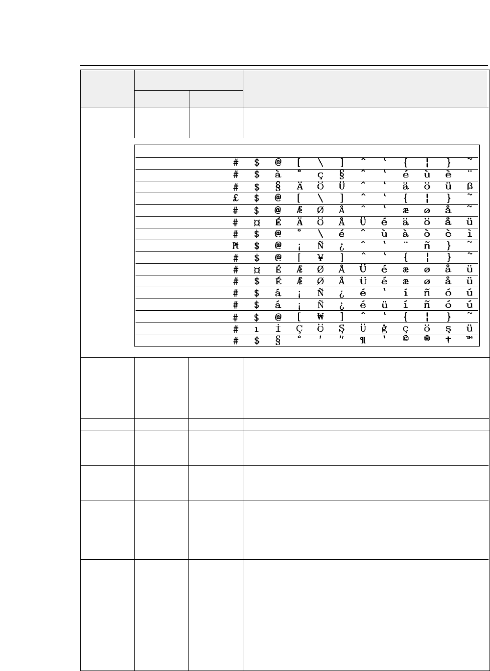
ESC R (27)D(82)D (1B)H (52)H
Selects a national character type.
(0 ≤n ≤13, 31, 64)
nn n
ESC S (27)D(83)D (1B)H (53)H
Specifies superscript or subscript.
n n n n = 00, 30
: Specifies superscript.
n = 01, 31
: Specifies subscript.
Characters corresponding to the graphic character sets
(B0)H to
(DF)H, (F4)H and (F5)H
are invalid.
ESC T (27)D(84)D (1B)H (54)H
Cancels superscript or subscript.
ESC U (27)D(85)D (1B)H (55)H
Specifies or cancels uni-directional printing.
n n n n = 00, 30
: Cancels uni-directional printing.
n = 01, 31
: Specifies uni-directional printing.
ESC W (27)D(87)D (1B)H (57)H
Specifies or cancels double-width printing.
n n n n = 00, 30
: Cancels double-width printing.
n = 01, 31
: Specifies double-width printing.
ESC Y (27)D(89)D (1B)H (59)H Specifies the
8-dot, double-speed, double-density graphic mode.
n1 n2 n1 n2 n1 n2
Number of data
k = n1 + n2 x 256
d1 d2 d1 d2 d1 d2
Horizontal dot density
: 120 dpi
••• dk ••• dk ••• dk
Maximum dots per line:
1632 dot
Horizontally adjacent dots cannot be printed.
ESC Z (27)D(90)D (1B)H (5A)H Specifies the
8-dot, quadruple-density graphic mode.
n1 n2 n1 n2 n1 n2
Number of data
k= n1 + n2 x 256
d1 d2 d1 d2 d1 d2
Horizontal dot density
: 240 dpi
••• dk ••• dk ••• dk
Maximum dots per line
: 3264 dot
Horizontally adjacent dots cannot be printed.
●
EPSON Software commands
Decimal Hex
Symbol Function
Code
8-6 — 8. Software commands —
nNATION 23 24 40 5B 5C 5D 5E 60 7B 7C 7D 7E
0 U.S.A.
1 FRANCE
2 GERMANY
3 U.K.
4 DENMARK
5 SWEDEM
6 ITALY
7 SPAIN
8 JAPAN
9 NORWAY
10 DENMARK II
11 SPAIN II
12 LATIN AMERICA
13 KOREA
31 TURKEY
64 LEGAL
ESC \ (27)D(92)D (1B)H (5C)H
Specifies the relative printing position.
n1 n2 n1 n2 n1 n2
Specifies where to start printing of the next data in relation to
the current position as shown below.
If (n1+n2×256) is less than 32768 [8000H], the printing position
moves to the right of the current position by (n1+n2×256).
If (n1+n2×256) is equal to or more than 32768 [8000H], the
printing position moves to the left of the current position by
65536 – (n1+n2 ×256).
Printing mode Unit of motion
Draft
1/ 120 inch
LQ or proportional
1/ 180 inch
ESC a (27)D(97)D (1B)H (61)H
Selects the printing position adjustment.
n n n n = 00, 30
: Left justification
n = 01, 31
: Centering
n = 02, 32
: Right justification
n = 03, 33
: Justification
Left justification is selected by default.
ESC b (27)D(98)D (1B)H (62)H
Specifies the vertical tab position in each channel.
m m m (0 ≤m ≤7, 1 ≤nk ≤255, 1 ≤k ≤16)
n1 n2 n1 n2 n1 n2
This command specifies the vertical tab position in channel m.
••• nk ••• nk ••• nk
A maximum of 16 vertical tab positions can be specified.
NUL NUL NUL
m: Channel number
If mis equal to or more than 8, three bytes of ESC b m are
ignored.
ESC g (27)D(103)D (1B)H (67)H
Selects
15CPI.
Valid when #34 PITCH LOCK is set to NO.
ESC j (27)D(106)D (1B)H (6A)H
Executes reverse feeding at a pitch of
n/180
inch
. (0 ≤n ≤255)
nn n
ESC k (27)D(107)D (1B)H (6B)H
Selects the font.
nn n n
Font
(00)H ROMAN
(01)H SANS SERIF
(02)H COURIER
(03)H PRESTIGE ELITE
(04)H SCRIPT
(05)H OCR-B
(06)H OCR-A
(07)H ORATOR
(08)H ORATOR-S
(14)H GOTHIC
●
EPSON Software commands
Decimal Hex
Symbol Function
Code
8-7
— 8. Software commands —
ESC l (27)D(108)D (1B)H (6C)H
Specifies the left margin.
nn n
This command sets the left margin at the “n”th character by the
character width when the command is executed (including
double- width and inter-character SP).
ESC p (27)D(112)D (1B)H (70)H
Specifies or cancels proportional printing.
n n n n = 00, 30
: Cancels proportional printing.
n = 01, 31
: Specifies proportional printing.
The draft and LQ modes have no difference for the proportional
printing. This command is valid when #34 PITCH LOCK is set
to NO.
ESC q (27)D(113)D (1B)H (71)H
Selects a special effect.
nn n
n =
00: Normal character
n =
01: Outline character
n = 02
: Shadow character
n = 03
: Outline with shadow character
Normal characters are selected by default.
Any characters corresponding to the graphic character sets
(B0)H to (DF)H and (F4)H to (F5)H.
ESC t (27)D(116)D (1B)H (74)H
Selects a character code table.
n n n n = 00, 30
: Selects the italic character table.
n = 01, 31
: Selects the graphic character table.
n = 02, 32
: Selects the downloaded character table.
n = 03, 33
: Selects the graphic character table.
If downloaded characters cannot be printed when the
downloaded character table is selected, italic characters are
printed. The selected character table is changed with the
ETS ( t
command.
ESC w 27)D(119)D (1B)H (77)H
Specifies or cancels double-height printing.
n n n n = 00, 30
: Cancels double-height printing.
n = 01, 31
: Specifies double-height printing.
Double-height printing does not apply to the graphic data.
ESC x (27)D(120)D (1B)H (78)H
Selects character.
n n n n = 00, 30
: Selects draft characters.
n = 01, 31
: Selects LQ characters.
●
EPSON Software commands
Decimal Hex
Symbol Function
Code
8-8 — 8. Software commands —
— 8. Software commands —
●
IBM Software commands
BEL (07)D (07)H
Activates the printer buzzer.
BS (08)D (08)H
Moves the printing position to the left by one character.
HT (09)D (09)H
Moves the printing position to the following horizontal tab.
LF (10)D (0A)H
Single-line feed
Causes carriage return if #28 LF SETTING is set to CR + LF in
the EXTENDED SETUP MODE.
VT (11)D (0B)H
Vertical tab
Moves the printing position to the left margin if #28 LF
SETTING is set to CR + LF in the EXTENDED SETUP MODE.
FF (12)D (0C)H
Form feed (Always moves the printing position to the left margin.)
CR (13)D (0D)H
Carriage return
Executes line feeding after carriage return if #27 CR SETTING
is set to CR + LF.
SO (14)D (0E)H
Double-width printing on a single line.
SI (15)D (0F)H
Specifies condensed mode.
Valid when #34 PITCH LOCK is set to NO in the EXTENDED
SETUP MODE.
DC1 (17)D (11)H
Printer select
Changes the deselect condition established with
ESC Q (23)H or
(B9)H
to the select condition.
Valid when #71 SELECT IN ENABLE is set to 1 in the
EXTENDED SETUP MODE or SELECT IN ENABLE is set to
I/F and the SELECT IN signal is high.
DC2 (18)D (12)H
Cancels the condensed mode.
Valid when #34 PITCH LOCK is set to NO in the EXTENDED
SETUP MODE.
DC4 (20)D (14)H
Cancels the double-width mode established by the SO command.
CAN (24)D (18)H
Cancel
Clears all data in the print buffer and moves the printing
position to the beginning of the next line.
ESC (27)D (1B)H
Designates ESC sequence.
ESC EM (27)D(25)D (1B)H (19)H
Specifies the paper path.
nn n
n="R" : Ejects paper.
n="B" : Feeds paper with the rear tractor.
n="F" : Feeds paper with the front tractor.
n="M" : Feeds manually loaded paper.
n="f" : Ejects paper to the front.
n="t" : Ejects paper to the top.
n="r" : Ejects paper to the rear.
Decimal Hex
Symbol Function
Code
8-9
IBM Software commands
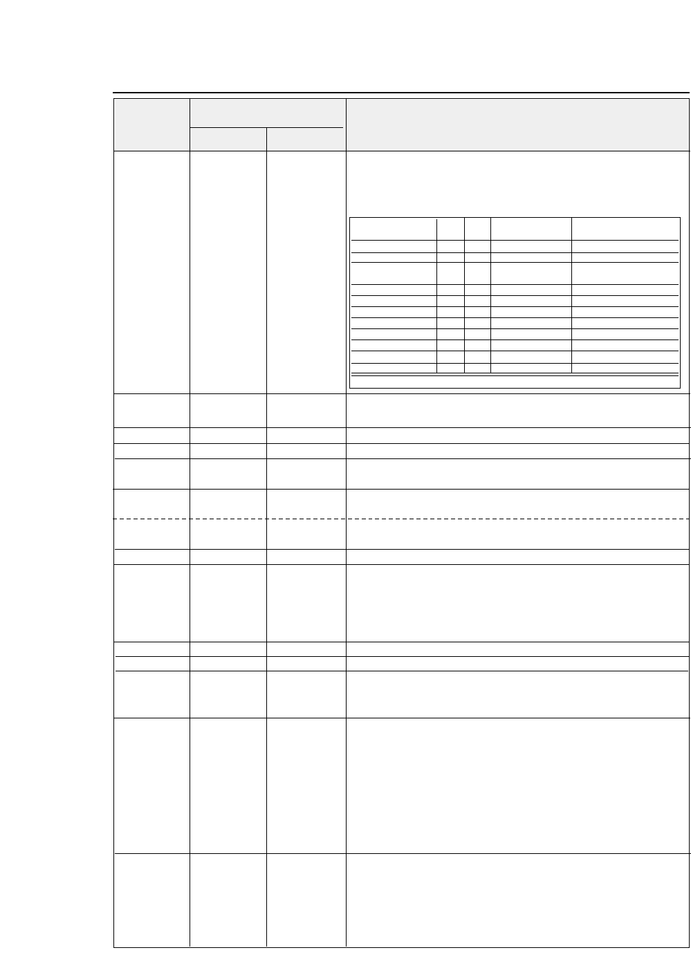
— 8. Software commands —
ESC
✽
(27)D (42 )D (1B)H (2A)H
Selects a graphic function.
m m m
Valid only when
#26 AGM (Alternate Graphics Mode)
is set to
n1 n2 n1 n2 n1 n2 YES
in the EXTENDED SETUP MODE.
d1 d2 d1 d2 d1 d2
m(
printing density
)= 0, 1, 2, 3, 4, 6, 32, 33, 38,
39, 40
... dk ... dk ... dk
ESC – (27)D (45 )D (1B)H (2D)H
Specifies or cancels underscoring.
(n = 0, 1)
nn n
ESC 0 (27)D (48 )D (1B)H (30)H
Specifies line feed at a 1/8-inch pitch.
ESC 1 (27)D (49 )D (1B)H (31)H
Specifies line feed at a 7/72-inch pitch.
ESC 2 (27)D (50 )D (1B)H (32)H
Executes
ESC A.
Sets the line feed pitch to the value specified by
ESC A.
ESC 3 (27)D (51 )D (1B)H (33)H
Specifies
n/216
-inch line feed pitch
. {1 ≤n ≤255}
nn n When n=0, this command is invalid.
ESC 3 (27)D (51 )D (1B)H (33)H
Specifies n/180 -inch line feed pitch.
(AGM) {1 ≤n ≤255}
nn n
Setting of n = 0 is possible.
ESC 4 (27)D(52)D (1B)H (34)H TOF
Specifies.
ESC 5 (27)D(53)D (1B)H (35)H
Specifies or cancels automatic line feeding.
{n = 0, 1}
nn n
Specifies whether to execute a carriage return and a line feed
or a carriage return only when executing the CR code.
n=0
: Carriage return only
n=1
: Carriage return and line feeding
ESC 6 (27)D(54)D (1B)H (36)H
Specifies character set 2.
ESC 7 (27)D(55)D (1B)H (37)H
Specifies character set 1.
ESC : (27)D(58)D (1B)H (3A)H
Specifies
12 CPI.
Valid when #34 PITCH LOCK is set to NO in the EXTENDED
SETUP MODE.
ESC = (27)D(61)D (1B)H (3D)H
Specifies downloading.
n1 n2 n1 n2 n1 n2 {0 ≤n1 ≤255} {0 ≤n2 ≤255} {I.D.byte = (23)H}
(I.D.byte) (I.D.byte) (I.D.byte) {(00)H ≤(adrs-low) ≤(FF)H} {(00)H ≤(adrs-high) ≤(FF)H}
(adrs-low) (adrs-low) (adrs-low) {(00)H ≤data ≤(FF)H}
(adrs-high) (adrs-high) (adrs-high)
The number of following data:
n1+n2
×
256.
data data data
When
n1=n2=0
, the downloading area is initialized. Two bytes,
(adrs-low)(adrs-high)
show the memory address in which the first
byte of data is stored. The next data is stored in the following
address in sequence.
ESC A (27)D(65)D (1B)H (41)H
Specifies the line feed pitch in units of
n/72 inch. {1 ≤n ≤255}
nn n
Specifies the line feed pitch in units of n/72 inch. When n = 0,
this command is invalid.
●
IBM Software commands
Decimal Hex
Symbol Function
Code
8-10
Mode Pin m Horizontal dot density Max. dots per line
dpi (dot/inch)
Single-density 8 0 60 Same as ESC K
Double-density 8 1 120 Same as ESC L
Double-speed 8 2 120 Same as ESC Y
double-density❈
Quadruple-density ❈8 3 240 Same as ESC Z
CRT I 8 4 80 CRT I
CRT II 8 6 90 CRT II
Single-density 24 32 60 High density of ESC K
Double-density 24 33 120 High density of ESC L
CRT III 24 38 90 CRT III
Triple-density 24 39 180 Triple high density
Hex-density❈24 40 360 Quadruple high density
❈Horizontally adjacent dots can not be printed.
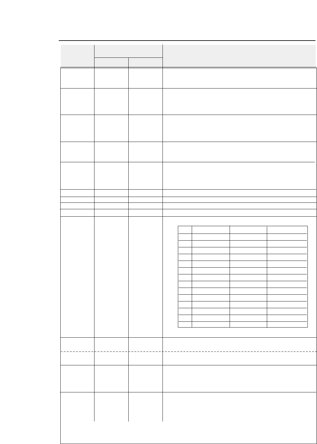
ESC A (27)D(65)D (1B)H (41)H
Specifies the line feed pitch in units of n/60 inch
{1 ≤n ≤255} (AGM)
nn n
Specifies the line feed pitch in units of n/60 inch.
When n = 0 , this command is invalid.
ESC B (27)D(66)D (1B)H (42)H
Specifies the vertical tabs.
d1 d2 d1 d2 d1 d2
A maximum of 64 tabs can be specified.
••• dk ••• dk ••• dk
Specify vertical tabs from the lowest tab and end with (00)H.
NUL (00)D (00)H
ESC C (27)D(67)D (1B)H (43)H
Specifies the page length in number of lines.
{1 ≤n ≤255}
nn n
The maximum page length is 182 inches.
Valid when #32 PAGE LOCK is set to NO in the
EXTENDED SETUP MODE.
ESC C (27)D(67)D (1B)H (43)H
Specifies the page length in inches.
{1 ≤n ≤182}
NUL n
(00)D
n
(00)H
n
Valid when #32 PAGE LOCK is set to NO in the
EXTENDED SETUP MODE.
ESC D (27)D (68 )D (1B)H (44)H
Specifies the horizontal tabs.
d1 d2 d1 d2 d1 d2
A maximum of 28 tabs can be specified.
••• dk ••• dk ••• dk
Specify horizontal tabs from the lowest tab and end with (00)H.
NUL (00)D (00)H
ESC E (27)D(69)D (1B)H (45)H
Specifies emphasized printing.
ESC F (27)D(70)D (1B)H (46)H
Cancels emphasized printing.
ESC G (27)D(71)D (1B)H (47)H
Specifies double-striking.
ESC H (27)D(72)D (1B)H (48)H
Cancels double-striking.
ESC I (27)D(73)D (1B)H (49)H
Selects a font.
n = 0, 2, 3, 4, 6, 7, 8, 10, 12, 14, 16, 18, 20, 22
nn n
If the value “n” is not as specified above, this command is invalid.
ESC J (27)D(74)D (1B)H (4A)H
Executes line feeding at a pitch of n/216 inches.
(1 ≤n ≤255)
nn n
ESC J (27)D(74)D (1B)H (4A)H
Executes line feeding at a pitch of n/180 inches.
(AGM) (1 ≤n ≤255)
nn n
ESC K (27)D(75)D (1B)H (4B)H Specifies the 8-dot single- density graphic mode.
n1 n2 n1 n2 n1 n2
Number of data
k = n1 + n2 x 256
d1 d2 d1 d2 d1 d2 Horizontal dot density : 60dpi
••• dk ••• dk ••• dk
Maximum dots per line:
816 dot
ESC L (27)D(76)D (1B)H (4C)H Specifies the 8-dot double-density graphic mode.
n1 n2 n1 n2 n1 n2
Number of data
k = n1 + n2 x 256
d1 d2 d1 d2 d1 d2
Horizontal dot density : 120dpi
••• dk ••• dk ••• dk
Maximum dots per line
: 1632 dot
— 8. Software commands —
●
IBM Software commands
Decimal Hex
Symbol Function
Code
8-11
nInternal/download Character quality Character width
0 Internal font Draft 10 CPI
2 Internal font LQ 10 CPI
3 Internal font LQ Proportional
4 Download Draft 10 CPI
6 Download LQ 10 CPI
7 Download LQ Proportional
8 Internal font Draft 12 CPI
10 Internal font LQ 12 CPI
12 Download Draft 12 CPI
14 Download LQ 12 CPI
16 Internal font Draft Condensed
18 Internal font LQ Condensed
20 Download Draft Condensed
22 Download LQ Condensed
— 8. Software commands —
ESC N (27)D(78)D (1B)H (4E)H
Specifies the bottom margin.
(1 ≤n ≤255)
nn n
The number of lines to be skipped is specified by “n” and the
bottom margin is specified in the preset line feed amount.
ESC O (27)D(79)D (1B)H (4F)H
Cancels the bottom margin.
ESC P (27)D(80)D (1B)H (50)H
Specifies or cancels proportional printing.
n n n n = 0
: Cancels proportional printing.
n = 1
: Specifies proportional printing.
This command is valid when #34 PITCH LOCK is set to NO.
ESC Q (27)D(81)D (1B)H (51)H
Printer deselect
nn n
Brings the printer into the deselect state when
n=(23)H,(B9)H.
Valid when #71 SELECT IN ENABLE is set to 1 in the
EXTENDED SETUP MODE or set to I/F and the SELECT IN
signal is high.
ESC R (27)D(82)D (1B)H (52)H
Initializes the horizontal and vertical tab positions.
Clears the vertical tab position.
ESC S (27)D(83)D (1B)H (53)H
Specifies superscript or subscript.
n n n n = 0
: Specifies superscript.
n = 1
: Specifies subscript.
ESC T (27)D(84)D (1B)H (54)H
Cancels superscript or subscript.
ESC U (27)D(85)D (1B)H (55)H
Specifies or cancels uni-directional printing.
n n n n = 0
: Cancels uni-directional printing.
n = 1
: Specifies uni-directional printing.
ESC W (27)D(87)D (1B)H (57)H
Specifies or cancels double-width printing.
n n n n = 0
: Cancels double-width printing.
n = 1
: Specifies double-width printing.
ESC X (27)D(88)D (1B)H (58)H
Specifies the right and left margins.
{0 ≤n ≤255} {0 ≤m ≤255}
n m n m n m
ESC Y (27)D(89)D (1B)H (59)H
Specifies the 8-dot double-speed double-density graphic mode.
n1 n2 n1 n2 n1 n2
Number of data
k = n1 + n2
×
256
d1 d2 d1 d2 d1 d2
Horizontal dot density
: 120 dpi
••• dk ••• dk ••• dk
Maximum dots per line
: 1632 dot
Horizontally adjacent dots cannot be printed.
ESC Z (27)D(90)D (1B)H (5A)H
Specifies the quadruple-density graphic mode.
n1 n2 n1 n2 n1 n2
Number of data
k = n1 + n2
×
256
d1 d2 d1 d2 d1 d2
Horizontal dot density
: 240 dpi
••• dk ••• dk ••• dk
Maximum dots per line
: 3264 dot
Horizontally adjacent dots cannot be printed.
ESC [ - (27,91,45)D (1B, 5B, 2D)H
Specifies the line type.
n1 n2 n1 n2 n1 n2
Number of data
k = n1 + n2
×
256
m1 m2 m1 m2 m1 m2 m1 = 1 :
Underscore
m2 = 0
: Cancels the line specification.
m1 = 2
: Center line
m2 = 1
: Single line
m1 = 3
: Upper line
m2 = 2
: Double lines
m2 = 255
: Cancels the line specification.
●
IBM Software commands
Decimal Hex
Symbol Function
Code
8-12
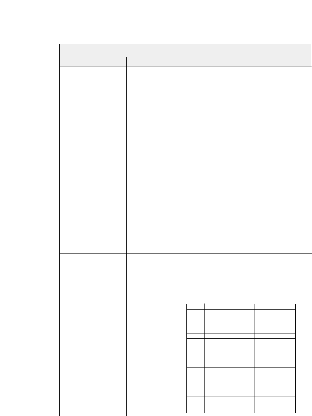
— 8. Software commands —
●
IBM Software commands
ESC [ @ (27,91,64)D (1B, 5B, 40)H
Specifies or cancels double-width, double-height printing.
n1 n2 n1 n2 n1 n2 n1+n2
×
256
indicates the number of following data.
Normally,
n1=4 and n2=0.
m1 m2 m1 m2 m1 m2 {n1 = 4} {n2 = 0} {m1 = 00, 01, 02, 04, 08, 10, 20 H}
m3 m4 m3 m4 m3 m4 {m3 = 00, 01, 02, 10, 11, 12, 20, 21, 22 H}
{m4 = (00)H, (01)H, (02)H)} {m2 = 0}
This command specifies or cancels double-height, double-width
printing.
m1 = 1
: Specifies italic characters.
m1 = 2
: Cancels italic characters.
m1 = 4
: Specifies the outline characters.
m1 = 8
: Cancels the outline characters.
m1 = 16
: Specifies shadow characters.
m1 = 32
: Cancels shadow characters.
m2 :
Meaningless
m3 : High order half-byte (4 bit)
indicates
Line Feed.
Low order half-byte (4 bit)
indicates
High.
m4 : Low order half-byte (4 bit)
indicates
Width.
Line Feed indicates the mode where the line feed pitch is
doubled. High indicates the mode where the height is doubled.
Width indicates the mode where the width is doubled.
Setting is;
0
: Not changed
1
: Standard size
2
: Double size
3
or more: Same as 0.
Graphic symbols are printed in the standard size.
ESC [ K (27,91,75)D (1B, 5B, 4B)H
Software initial
n1 n2 n1 n2 n1 n2 n1+n2
×
256
indicates the number of the next data.
m1 m2 m1 m2 m1 m2
When
m1 =00, 04, FE H
, initialization is executed without clearing
m3 m4 m3 m4 m3 m4 downloading.
m1 =01, 05, FF H
,initialization is executed with clearing
download area.
m2 = 03, 16, 23, 24, B1, B4 H
,the next two bytes of data are valid.
Decimal Hex
Symbol Function
Code
8-13
m 3 m 4
bit 7 0 : m 3 is valid. 0 : m 4 is valid.
1 : m 3 is invalid. 1 : m 4 is invalid.
bit 6 ————— Code page
0 : 437
1 : 850
bit 5 ————— —————
bit 4 LF code —————
0 : LF only
1 : LF + CR
bit 3 CR code —————
0 : C R only
1 : CR + LF
bit 2 Page length —————
0 : 11 inches
1 : 12 inches
bit 1 Zero font Printing range
0 : No slash 0 : 13.6 inches
1 : With slash 1 : 8 inches
bit 0 Character set —————
0 : Set 1
1 : Set 2
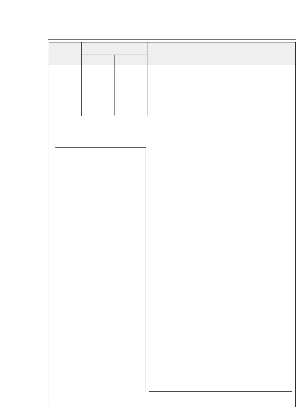
— 8. Software commands —
ESC [ I (27,91,73)D (1B, 5B,49)H
Selects the font.
n1 n2 n1 n2 n1 n2 n1 + n2 x 256
indicates the number of the next data.
Hf Lf Hf Lf Hf Lf Hf, Lf = FONT ID
Hs Ls Hs Ls Hs Ls Hs, Ls =
Size (pitch & height)
Sm 00 Sm 00 Sm 00 Sm = 1
: Font size is specified with Hs, Ls.
Hc Lc Hc Lc Hc Lc Sm = 2 or 3
: Specifies proportional printing.
Hs, Ls, Sm is valid only when the font ID specified with Hf, Lf
is invalid or ignored.
Hc, Lc specifies the code page.
The following table shows the relationship between the Hf, Lf
values and fonts.
●
IBM Software commands
Decimal Hex
Symbol Function
Code
8-14
Hf Lf
(00)H (0B)H COURIER 10CPI
(01)H (EB)H COURIER 12CPI
(01)H (EC)H COURIER 15CPI
(01)H (ED)H COURIER 17CPI
(01)H (EE)H COURIER 20CPI
(01)H (1E)H COURIER 24CPI
(00)H (AB)H COURIER PROP
(00)H (0C)H PRESTIGE 10CPI
(01)H (EF)H PRESTIGE 12CPI
(01)H (F0)H PRESTIGE 15CPI
(01)H (C9)H PRESTIGE 17CPI
(01)H (CA)H PRESTIGE 20CPI
(01)H (1F)H PRESTIGE 24CPI
(00)H (A4)H PRESTIGE PROP
(00)H (24)H GOTHIC 10CPI
(01)H (8F)H GOTHIC 12CPI
(01)H (8E)H GOTHIC 15CPI
(01)H (8D)H GOTHIC 17CPI
(01)H (8C)H GOTHIC 20CPI
(01)H (20)H GOTHIC 24CPI
(00)H (AE)H GOTHIC PROP
(00)H (19)H ORATORs 10CPI
(01)H (D0)H ORATORs 12CPI
(01)H (D1)H ORATORs 15CPI
(01)H (D2)H ORATORs 17CPI
(01)H (D3)H ORATORs 20CPI
(01)H (23)H ORATORs 24CPI
(00)H (C7)H ORATORs PROP
(00)H (05)H ORATOR 10CPI
(01)H (CB)H ORATOR 12CPI
(01)H(CC)H ORATOR 15CPI
(01)H(CD)H ORATOR 17CPI
(01)H (CE)H ORATOR 20CPI
(01)H (21)H ORATOR 24CPI
(00)H (C6)H ORATOR PROP
Hf Lf
(01)H (D4)H SCRIPT 10CPI
(01)H (D5)H SCRIPT 12CPI
(01)H (D6)H SCRIPT 15CPI
(01)H (D7)H SCRIPT 17CPI
(01)H (D8)H SCRIPT 20CPI
(01)H (24)H SCRIPT 24CPI
(00)H (C8)H SCRIPT PROP
Hf Lf
(00)H (12)H COURIER 10CPI Italic
(00)H(2E)H COURIER 10CPI Emphasized
(00)H (39)H COURIER 10CPI Emphasized italic
(00)H (55)H COURIER 12CPI
(00)H(5C)H COURIER 12CPI Italic
(00)H(6C)H COURIER 12CPI Emphasized
(00)H (74)H COURIER 12CPI Emphasized italic
(00)H(AC)H COURIER PROP Italic
(00)H(B8)H COURIER PROP Emphasized
(00)H(B9)H COURIER PROP Emphasized italic
(00)H(D6)H COURIER 15CPI Emphasized
(00)H(D7)H COURIER 15CPI Italic
(00)H(D8)H COURIER 15CPI Emphasized italic
(00)H(DF)H COURIER 15CPI
(00)H (F6)H COURIER 10CPI Double-width, double-height
(00)H (F4)H COURIER 10CPI Double-width, double-height
(00)H (F5)H COURIER 10CPI Emphasized double-width, double-height
(00)H(FD)H COURIER 17.1CPI Emphasized
(00)H(FE)H COURIER 17.1CPI
(00)H(3C)H PRESTIGE 10CPI Emphasized
(00)H (56)H PRESTIGE 12CPI
(00)H (6F)H PRESTIGE 12CPI Emphasized
(00)H (70)H PRESTIGE 12CPI Italic
(00)H(DD)H PRESTIGE 15CPI
(01)H (00)H PRESTIGE 17.1CPI
— 8. Software commands —
●
IBM Software commands
Function
8-15
Hf Lf
(00)H (57)H GOTHIC 12CPI
(00)H (6D)H GOTHIC 12CPI Italic
(00)H (6E)H GOTHIC 12CPI Emphasized
(00)H (9D)H GOTHIC PROP Emphasized
(00)H (A2)H GOTHIC PROP Italic
(00)H (DE)H GOTHIC 15CPI
(00)H (F1)H GOTHIC 10CPI Double-width,
double-height
(00)H (F2)H GOTHIC 10CPI Emphasized
Double-width,
double-height
(00)H (F3)H GOTHIC 10CPI Emphasized
Double-striking
Double-width,
double-height
(00)H (FF)H GOTHIC 17.1CPI
(01)H (19)H GOTHIC 20CPI
(32)H (00)H ROMAN 10CPI
(32)H (01)H ROMAN 12CPI
(32)H (02)H ROMAN 15CPI
(32)H (03)H ROMAN 17CPI
(32)H (04)H ROMAN 20CPI
(32)H (05)H ROMAN 24CPI
(32)H (06)H ROMAN PROP
(32)H (10)H SANS SERIF 10CPI
(32)H (11)H SANS SERIF 12CPI
(32)H (12)H SANS SERIF 15CPI
(32)H (13)H SANS SERIF 17CPI
(32)H (14)H SANS SERIF 20CPI
(32)H (15)H SANS SERIF 24CPI
(32)H (16)H SANS SERIF PROP
(32)H (20)H OCR-A 10CPI
(32)H (21)H OCR-A 12CPI
(32)H (23)H OCR-A 17CPI
(32)H (24)H OCR-A 20CPI
(32)H (30)H OCR-B 10CPI
(32)H (31)H OCR-B 12CPI
(32)H (33)H OCR-B 17CPI
(32)H (34)H OCR-B 20CPI
The following shows the relationship between the
Hs, Ls values and sizes.
Hs,Ls
00,00-00,41 24CPI Subscript
00,42-00,4D 20CPI Subscript
00,4E-00,59 17CPI Normal
00,5A-00,6B 15CPI Normal
00,6C-00,83 12CPI Normal
00,84-00,9B 10CPI Normal
00,9C-00,B3 17CPI Double-width
00,B4-00,D7 15CPI Double-width
00,D8-00,FE 12CPI Double-width
Double-hight
00,FF-FF,FF 10CPI Double-width
Double-hight
The following shows the relationship between the
Hc, Lc values and the code page.
Hc Lc Dec(Hc,Lc) CODE PAGE
(01)H (B5)H 437 CODE PAGE 437
(03)H (52)H 850 CODE PAGE 850
(03)H (5C)H 860 CODE PAGE 860
(03)H (5F)H 863 CODE PAGE 863
(03)H (61)H 865 CODE PAGE 865
(03)H (59)H 857 CODE PAGE 857
(03)H (5A)H 858 CODE PAGE 858
(40)H (00)H 16384 ISO-8859-1
(03)H (5d)H 861 CODE PAGE 861
(0F)H (07)H 3847 CODE PAGE BRASCII
(0F)H (08)H 3848
CODE PAGE ABICOMP
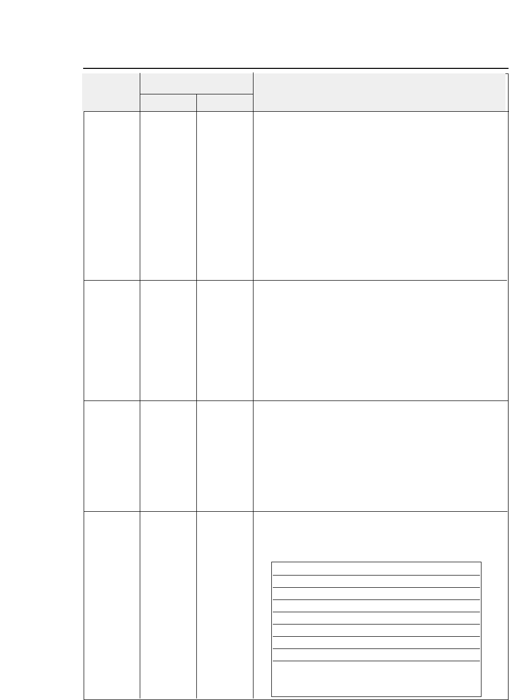
— 8. Software commands —
ESC [ T (27,91,84)D (1B, 5B, 54)H
Selects the code page.
(n1=4 n2=0 n3=0 n4=0)
n1 n2 n1 n2 n1 n2 n1 + n2 x 256
indicates the number of the next data.
n3 n4 n3 n4 n3 n4 n5=(01)H n6=(B5)H 437
n5 n6 n5 n6 n5 n6 (03)H (52)H 850
(03)H (59)H 857
(03)H (5A)H 858
(03)H (5C)H 860
(03)H (5F)H 863
(03)H (61)H 865
(40)H (00)H ISO-8859-1
(03)H (5D)H 861
(0F)H (07)H BRASCII
(0F)H (08)H ABICOMP
ESC [ \ (27,91,92)D (1B, 5B, 5C)H
Specifies the basic amount of line feeding.
n1 n2 n1 n2 n1 n2 (n1=4 n2=0 m1=0 m2=0 m3=0,104,180,216 m4=0,1,180,216)
m1 m2 m1 m2 m1 m2 n1 + n2 x 256
indicates the number of the next data.
m3 m4 m3 m4 m3 m4 When m3=0 and m4=216 or m3=216 and m4=0 ,
the basic line
feed pitch is 1/216 inch.
When m3=0 and m4=180 or m3=180 and m4=0
, the basic line
feed pitch is 1/180 inch.
When m3=104 and m4=1, the basic line feed pitch is 1/360 inch.
The basic line feed pitch is 1/216 inch (when not in the AGM
mode) or 1/180 inch (in the AGM mode) by default.
ESC [ d (27,91,100)D (1B, 5B, 64)H
Selects character quality.
(n1=1 n2=0)
n1 n2 n1 n2 n1 n2 n1 + n2 x 256
indicates the number of the next data.
n3 n3 n3 n3 = 0
: Not changed.
n3 =(01)H - (7F)H
Draft
n3 =(80)H - (BF)H
LQ
n3 =(C0)H -(FE)H
Emphasized LQ
n3 =(FF)H
LQ
Valid when #35 QUALITY LOCK is set to NO in the
EXTENDED SETUP MODE.
ESC [ g (27,91,103)D (1B, 5B, 67)H
Graphic mode
n1 n2 n1 n2 n1 n2 n1+n2
×
256
specifies (graphic data + 1).
m m m {0 ≤n1 ≤255}{0 ≤n2 ≤255} {m = 0, 1, 2, 3, 8, 9, 11, 12, 16}
d1 d2 d1 d2 d1 d2 m
indicates the graphic mode (density) as shown below.
••• dk ••• dk ••• dk
●
IBM Software commands
Decimal Hex
Symbol Function
Code
8-16
m = 0 8 pin 60 dpi
1 8 120
2 8 120 (*)
3 8 240 (*)
824 60
9 24 120
11 24 180
12 24 360 (*)
16 48 360 (*)
In a graphic mode marked with an asterisk
(*)
horizontally adjacent dots cannot be printed.
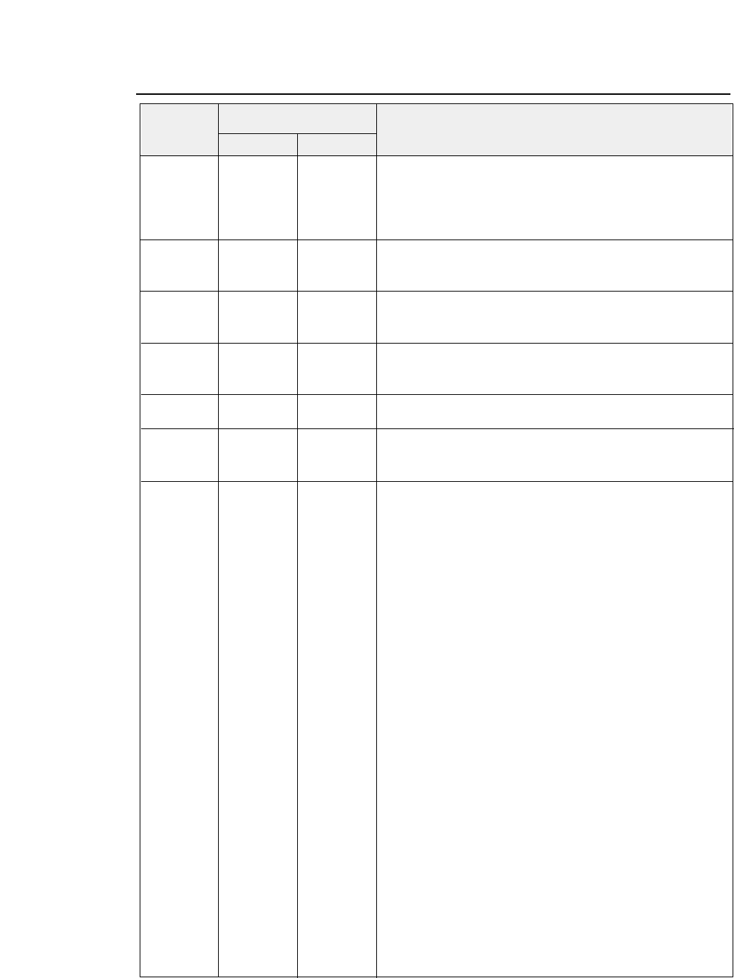
— 8. Software commands —
●
IBM Software commands
ESC \ (27)D (92)D (1B)H (5C)H
All-character set
{0 ≤n1 ≤255}{0 ≤n2 ≤255}
n1 n2 n1 n2 n1 n2
Prints n1 + n2 × 256 characters in the all-character character set.
d1 d2 d1 d2 d1 d2
•••dk •••dk •••dk
ESC ] (27)D (93)D (1B)H (5D)H
Reverse line feeding.
This command does not execute a carriage return even when an
automatic carriage return is specified.
ESC ^ (27)D (94)D (1B)H (5E)H
All-character set for a single character.
{0 ≤n ≤255}
n n n
Prints only one character following
ESC ^
in the all-character
character set.
ESC _(27)D (95)D (1B)H (5F)H
Specifies or cancels the upper line.
n n n n = 1
: Specifies the upper line.
n = 0
: Cancels the upper line.
ESC d (27)D (100)D (1B)H (64)H
Specifies the relative printing position.
{0 ≤n1 ≤255}{0 ≤n2 ≤255}
n1 n2 n1 n2 n1 n2
Advances the printing position by
(n1+n2
×
256)/120
inch.
ESC j (27)D (106)D (1B)H (6A)H
Stops printing.
After printing, this command activates the buzzer and disables
printing.
Decimal Hex
Symbol Function
Code
8-17
BEL (07)D (07)H Activates the printer buzzer. (Available in PCL3+ or PCL3+D)
BS (08)D (08)H Backspace one character.
HT (09)D (09)H Moves to next horizontal tab.
LF (10)D (0A)H Linefeeds after printing.
FF (12)D (0C)H Form feeds after printing.
CR (13)D (0D)H Carriage return after printing.
SO (14)D (0E)H Selects secondary font.
SI (15)D (0F)H Selects prinmary font.
ESC (27)D (1B)H Designate start of escape sequence.
SP (32)D (20)H Space one character.
DEL (127)D (7F)H To print the ASCII DEL character.
ESC & a (27,38,97,#, (1B,26,61,#, Horizontal positioning by column.
# C 67)D 43)H
ESC & a (27,38,97,#, (1B,26,61,#, Horizontal positioning by 1/720”.
# H 72)D 48)H
ESC & a (27,38,97,#, (1B,26,61,#, Sets left margin.
# L 76)D 4C)H
ESC & a (27,38,97,#, (1B,26,61,#, Sets right margin.
# M 77)D 4D)H
ESC & a (27,38,97,#, (1B,26,61,#, Vertical positioning by line (VMI).
# R 82)D 52)H
ESC & a (27,38,97,#, (1B,26,61,#, Vertical positioning by 1/720”.
# V 86)D 56)H
ESC & d (27,38,100,#, (1B,26,64,#, Designates underline mode.
# D 68)D 44)H
ESC & d (27,38,100,#, (1B,26,64,#, Cancels underline mode.
# @ 64)D 40)H
ESC & k (27,38,107,#, (1B,26,6B,#, Designates/Cancels the auto-cancellation of underline.
# E 69)D 45)H
ESC & k (27,38,107,#, (1B,26,6B,#, Designates/Cancels the auto-cancellation of secondary font.
# F 70)D 46)H If # is seto to “0”, current secondary font set changes
automatically to primary font when vertical position changes.
ESC & k (27,38,107,#, (1B,26,6B,#, Designates line termination.
# G 71)D 47)H # = 0 (30H) :CR=CR, LF=LF, FF=FF
# = 1 (31H) :CR=CR+LF, LF=LF, FF=FF
# = 2 (32H) :CR=CR, LF=LF+CR, FF=FF+CR
# = 3 (33H) :CR=CR+LF, LF=LF+CR, FF+CR
ESC & k (27,38,107,#, (1B,26,6B,#, Sets HMI (Horizontal motion index).
# H 72)D 48)H HMI is set by 1/120 inch.
HMI is defined as the distance where the print position moves
when the character code is input.
If # is 12, the input characters are printed in 10 cpi.
ESC & k (27,38,107,#, (1B,26,6B,#, Designates character pitch.
# S 83)D 53)H Character pitch is set.
# = 0 (30H) :Normal (10 cpi)
# = 1 (31H) :Double width (5 cpi)
# = 2 (32H) :Compressed (16.7 cpi)
# = 4 (34H) :12 cpi
●
HP Software commands
Decimal Hex
Symbol Function
Code
8-18 — 8. Software commands —
HP Software commands

●
HP Software commands
ESC & k (27,38,107,#, (1B,26,6B,#, Designates/Cancels automatic scroll mode.
# V 86)D 56)H # =0 (30H) :Designates automatic scroll mode.
# =1 (31H) :Cancels automatic scroll mode.
ESC & k (27,38,107,#, (1B,26,6B,#, Controls print direction. (Available in PCL3+ or PCL3+D)
# W 87)D 57)H Print direction is set as follows.
# = 0 (30H) :Unidirectional Print(left to right)
# = 1 (31H) :Bidirectional Print
# = 2 (32H) :Pre-directional Print
ESC & l (27,38,108,#, (1B,26,6C,#, Designates paper size.
# A 65)D 41)H Paper size is set as follows.
# = 0 (30H) :(Setting in the setup mode)
# = 2 (32H) :Letter
# = 3 (33H) :Legal
# = 26 (32H,36H) :A4
# = 81 (38H,31H) :ENVELOP Commercial-10
ESC & l (27,38,108,#, (1B,26,6C,#, Sets VMI (Vertical motion index).
# C 67)D 43)H VMI is set by 1/48 inch.
VMI is defined as the distance where the print position moves
when the LF code is input. If # is 8, the print position moves
in 6 LPI vertically.
ESC & l (27,38,108,#, (1B,26,6C,#, Sets the line spacing. VMI (Vertical motion index)
# D 68)D 44)H # = The number of LPI (lines per inch).
# = 8 (38H) :8 LPI
ESC & l (27,38,108,#, (1B,26,6C,#, Sets top margin by VMI. (where # = “1,2, ...)
# E 69)D 45)H When the top margin is set, the text length is set to the default.
In case of skip perforation ON
Text length = page length- top margin-1/2"
(Bottom margin is set to 1/2")
In case of skip perforation OFF
Text length = page length- top margin
(Bottom margin is set to 0")
ESC & l (27,38,108,#, (1B,26,6C,#, Sets text length.
# F 70)D 46)H Text length is set by line (VMI).
ESC & l (27,38,108,#, (1B,26,6C,#, Sets paper path.
# H 72)D 48)H The mode set as follows.
# = 0 (30H) :Ejects Paper.
# = 1 (31H) :Feeds paper with the CSF.
# = 2 (32H) :Feeds manually loaded paper.
# = -1 (2DH,31H) :Feeds paper with the front tractor.
# = -2 (2DH,32H) : Feeds paper with the rear tractor.
# = -10 (2DH,31H,30H) :Ejects paper to the front.
# = -11 (2DH,31H,31H) :Ejects paper to the top
# = -11 (2DH,31H,32H) :Ejects paper to the rear.
When the "NOT INSTALL" is selected in the" SETUP #60
OPTION," the CSF command is the same as #=0.
Decimal Hex
Symbol Function
Code
8-19
— 8. Software commands —
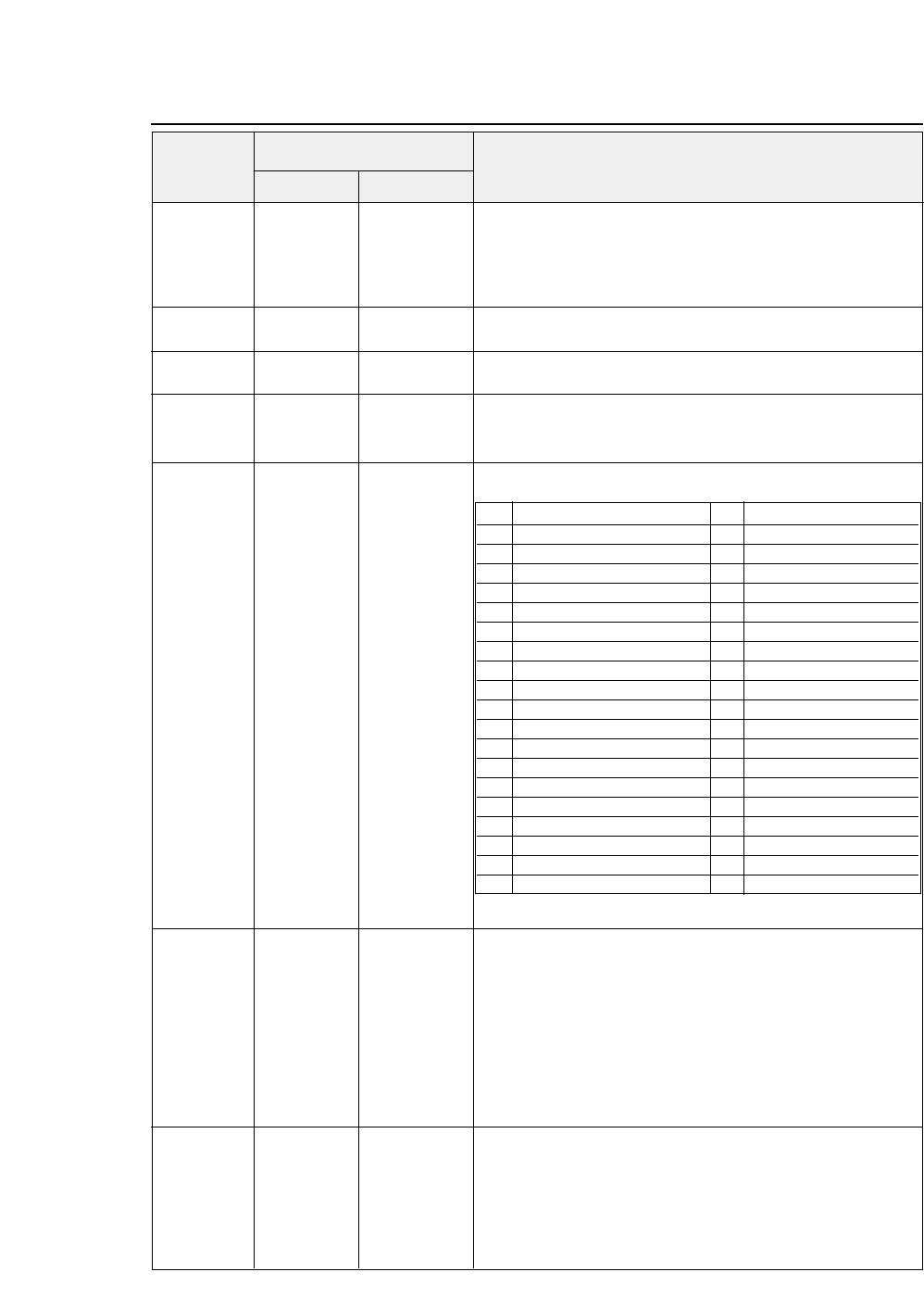
ESC & l (27,38,108,#, (1B,26,6C,#, Designates/Cancels skip perforation mode.
# L 76)D 4C)H Paper path is set as follows.
# = 0 (30H) :Cancels the skip perforation mode
# = 1 (31H) :Designates the skip perforation mode
ESC & l (27,38,108,#, (1B,26,6C,#, Sets page length by VMI.
# P 80)D 50)H
ESC & p (27,38,112,#, (1B,26,70,#, Receives data as text.
# X 88)D 58)H
ESC & s (27,38,115,#, (1B,26,73,#, Designates/Cancels wraparound.
# C 67)D 43)H # = 0 (30H) :Designates wraparound
# = 1 (31H) :Cancels wraparound
ESC ( (27,40,id)D (1B,28,id)H Assign font to the primary/secondary font set.
id
ESC ) (27,41,id)D (1B,29,id)H
id
✽: Avaliable in PCL3+ or PCL3+D mode
ESC ( # (27,40,#, (1B,28,#, Designates primary font.
@ 64)D 40)H # = 0 or 1 (30H or 31H) :
Copy the default primary symbol set to the current primary
symbol set.
# = 2 (32H) :
Copy the current primary symbol set to the current primary
symbol set.
# = 3 (33H) :
Copy the default primary font to the current primary font.
ESC ( 0 (27,40,48, (1B,28,30, Assigns the download font to the current primary/secondary
X 88)D 58)H font.
ESC ) 0 (27,41,48, (1B,29,30,
X 88)D 58)H
●
HP Software commands
Decimal Hex
Symbol Function
Code
8-20 — 8. Software commands —
id Font id Font
0 A MATH-SYMBOL ✽10U PC-8
0 B LINE-DRAW 11U PC-8, DENMARK/NORWAY
0 D ISO-60, NORWAY 1 12U PC-850
0 E ROMAN-EXTENSION 2 S ISO17,SPAIN 1
0 F ISO-25, FRANCE 2 ✽2 U ISO2, IRV
0 G GERMANY 2 ✽3 S ISO10, SWEDEN 2
0 I ISO15, ITALY 4 S ISO16, PORTUGAL 1
0 K ISO14, JIS, ASCI 5 S ISO84, PORTUGAL 2 ✽
0 L LINE-DRAW 6 S ISO85, SPAIN 2 ✽
0 M MATH 7 ✽8 U ROMAN-8
0 N ECMA 94, LATIN 1 (ISO-8859-1) 80U CODE PAGE 857 ✽
0 U ASCII 81U CODE PAGE 860 ✽
0 S ISO11, SWEDEN 1 82U CODE PAGE 863 ✽
1 D ISO61, NORWAY 2 83U CODE PAGE 865 ✽
1 E ISO4, UK 93U CODE PAGE 858 ✽
1 F ISO-69, FRANCE 1 94U CODE PAGE 861 ✽
1 G ISO-21, GERMANY 1 95U CODE PAGE BRASCII ✽
1 S SPAIN 3 ✽96U CODE PAGE ABICOMP ✽
1 U LEGAL ✽
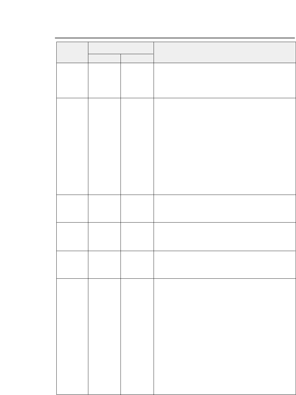
●
HP Software commands
ESC ( s (27,40,115,#, (1B,28,73,#, Bold or emphasized.
# B 66)D 42)H Designates/Cancels bold or emphasized attributes as follows.
ESC ) s (27,41,115,#, (1B,29,73,#, # = 0 (30H) :Bold off/Emphasized off
# B 66)D 42)H # = 3 (33H) :Bold on /Emphasized off
# = 7 (37H) :Bold off/Emphasized on
ESC ( s (27,40,115,#, (1B,28,73,#, Sets character spacing. (# = Font pitch (CPI))
# H 72)D 48)H PCL mode = PCL3+, PCL3+D or PCL3
ESC ) s (27,41,115,#, (1B,29,73,#, # = 5 :5 cpi (0.01≤#<5.01)
# H 72)D 48)H # = 10 :10 cpi (5.01≤#<10.01)
# = 12 :12 cpi (10.01≤#<12.01)
PCL mode = PCL3+ or PCL3+D
# = 15 :15 cpi (12.01≤#<15.01)
# = 16.7 :16.7 cpi (15.01≤#<16.71)
# = 17.1 :17.1 cpi (16.71≤#<17.11)
# = 20 :20 cpi (17.11≤#<20.01)
# = 24 :24 cpi (20.01≤#)
PCL mode = PCL3
# = 16.7 :16.7 cpi (12.01≤#<16.71)
# = 20 :20 cpi (16.71 ≤#)
ESC ( s (27,40,115,#, (1B,28,73,#, Selects proportional or fixed character spacing.
# P 80)D 50)H # = 1 (31H) :Proportional pitch
ESC ) s (27,41,115,#, (1B,29,73,#, # = 0 (30H) :Fixed pitch
# P 80)D 50)H
ESC ( s (27,40,115,#, (1B,28,73,#, Sets print quality.
# Q 81)D 51)H # = 0 (30H) :Draft
ESC ) s (27,41,115,#, (1B,29,73,#, # = 2 (32H) :Letter Quality
# Q 81)D 51)H
ESC ( s (27,40,115,#, (1B,28,73,#, Sets italic character.
# S 83)D 53)H # = 0 (30H) :Cancels italic character
ESC ) s (27,41,115,#, (1B,29,73,#, # = 1 (31H) :Designates italic character
# S 83)D 53)H # = 2 (32H) :Designates italic character
ESC ( s (27,40,115,#, (1B,28,73,#, Sets typeface.
# T 84)D 54)H # = 0 (30H) LINE PRINTER DRAFT
ESC ) s (27,41,115,#, (1B,29,73,#, # = 3 (33H) COURIER
# T 84)D 54)H # = 4 (34H) SANSERIF
# = 5 (35H) ROMAN
# = 6 (36H) GOTHIC
# = 7 (37H) SCRIPT*
# = 8 (38H) PRESTIGE
# = 10 (31H,30H) ORATOR*
# = 11 (31H,31H) ORATOR-S*
# = 20 (32H,30H) OCR-A*
# = 21 (32H,31H) OCR-B*
*= Available in PCL3+ or PCL3+D
Decimal Hex
Symbol Function
Code
8-21
— 8. Software commands —
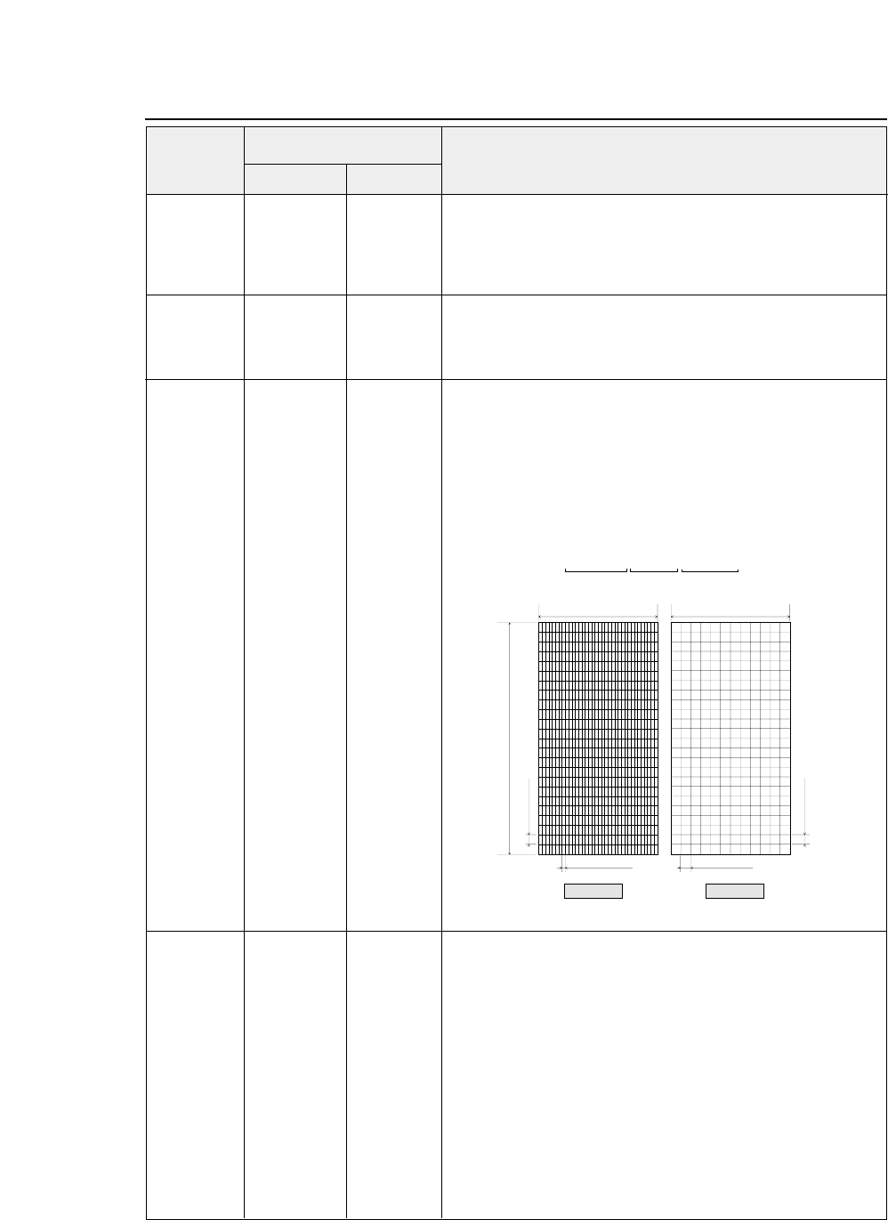
ESC ( s (27,40,115,#, (1B,28,73,#, Sets super/subscript.
# U 85)D 55)H # = + 1 (2BH,31H) :Designates superscript
ESC ) s (27,41,115,#, (1B,29,73,#, # = 0 (30H) :Cancels super/subscript
# U 85)D 55)H # = - 1 (2DH,31H) :Designates subscript
ESC ( s (27,40,115,#, (1B,28,73,#, Sets character point size.
# V 86)D 56)H # = 12 (31H,32H) :Standard font
ESC ) s (27,41,115,#, (1B,29,73,#, # = 8 (38H) :Micro font
# V 86)D 56)H
ESC ( s (27,40,115,#, (1B,28,73,#, Download character descriptor and data.
# W 87)D 57)H The parameter # consists of 3 bytes of the descriptor.
DATA DATA DATA <Attribute data format>
1 st 8 (Attribute format)
2 nd 0 (Continuation)
3 rd 1 (Acknowledge for the attribute data)
Dot pattern data stream is translated as follows:
ESC ) # (27,41,#, (1B,29,#, Designates secondary font.
@ 64)D 40)H # = 0(30H) :
Copy the default secondary symbol set to the current secondary
symbol set.
# = 1(31H) :
Copy the default primary symbol set to the current secondary
symbol set.
# = 2(32H) :
Copy the current primary symbol set to the current secondary
symbol set.
# = 3(33H) :
Copy the default secondary font to the current secondary font.
●
HP Software commands
Decimal Hex
Symbol Function
Code
8-22 — 8. Software commands —
1/180 dpi
1/180 dpi
1/360 dpi 1/120 dpi
A
A
A
A
A
A
A
A
B
B
B
B
B
B
B
B
C
C
C
C
C
C
C
C
D
D
D
D
D
D
D
D
E
E
E
E
E
E
E
E
F
F
F
F
F
F
F
F
G
G
G
G
G
G
G
G
A
A
A
A
A
A
A
A
B
B
B
B
B
B
B
B
C
C
C
C
C
C
C
C
D
D
D
D
D
D
D
D
E
E
E
E
E
E
E
E
F
F
F
F
F
F
F
F
G
G
G
G
G
G
G
G
36 dots
•••••••
AAAAAAAA BBBBBBBB CCCCCCCC
1 byte 1 byte 1 byte•••••••
Data stream
12 dots
24 dots
LQ DRAFT
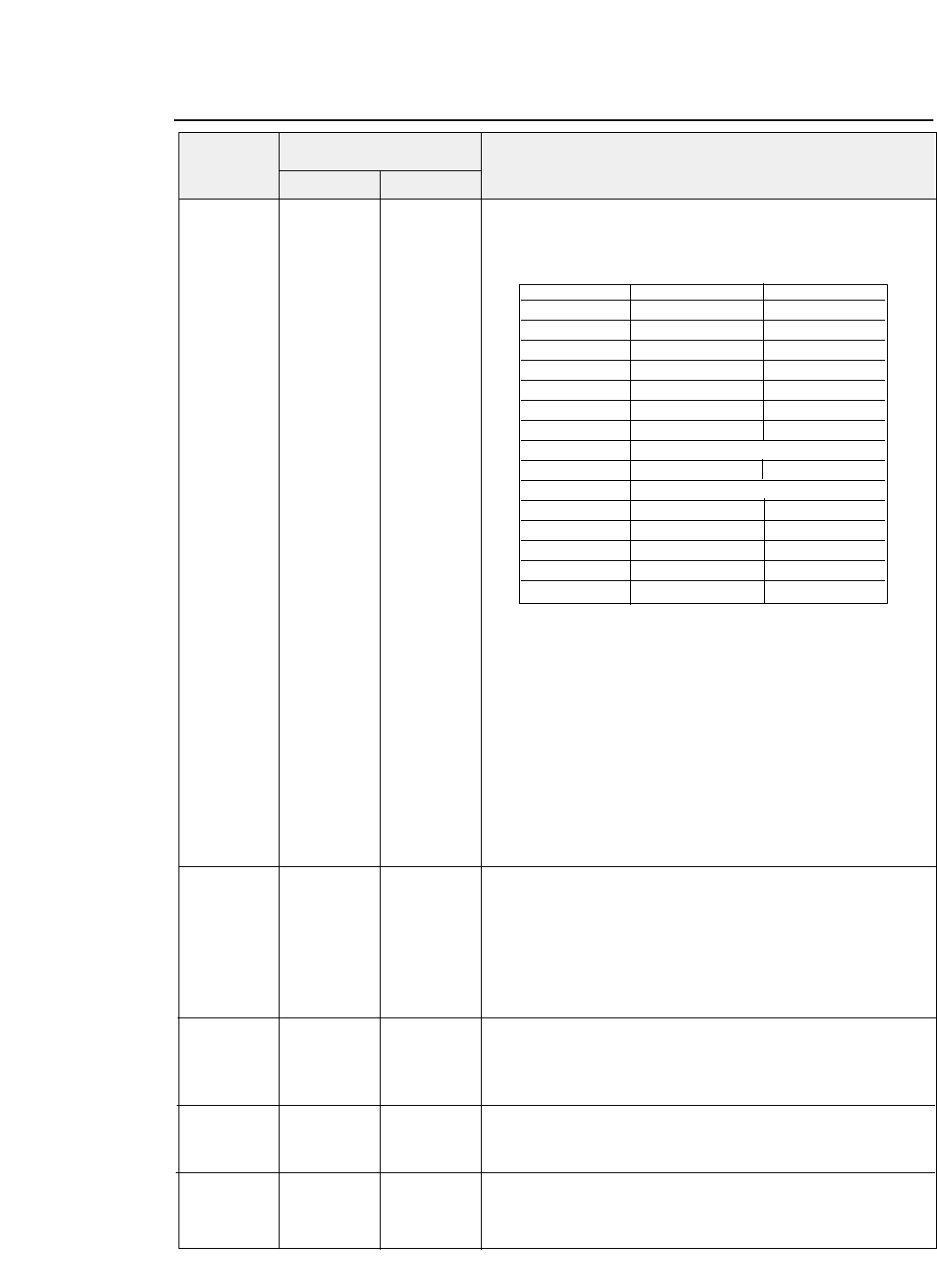
●
HP Software commands
ESC ) s (27,41,115,#, (1B,29,73,#, Download font descriptor.
# W 87)D 57)H ESC ) s 0 W command resistors a blank LQ font.
DATA DATA DATA The format is as follows.
Symbol set : Byte 14-15 represent the symbol set # and ID for the
download character to be selected by ESC ( # id command.
Example:Roman-8
8U”
32 x 8 + 85 - 64 = 277 (01H,15H)
Point size(character height): Point size in decimal is registered.
Typeface:Parameter used in the typeface selection command is
registered.
LQ/DRAFT:Print Quality, LQ or Draft is registered by the
following definition;
0:DRAFT 1:LQ
ESC * b (27,42,98,#, (1B,2A,62,#, Selects format the graphic data compression.
# M 77)D 4D )H Available in PCL3+ or PCL3+D
Raster graphics data are registered.
# = 0 :compression off
# = 1 :mode 1
# = 2 :mode 2
# = 3 :mode
ESC * b (27,42,98,#, (1B,2A,62,#, Designates raster graphic data transmission.
# W 87)D 57)H
DATA DATA DATA
ESC * b (27,42,98,#, (1B,2A,62,#, Sets temporary graphics X-offset.
# X 88)D 58)H
ESC * b (27,42,98,#, (1B,2A,62,#, Sets temporary graphics Y-offset.
# Y 89)D 59)H
Decimal Hex
Symbol Function
Code
8-23
— 8. Software commands —
Byte 0-1 0 0
Byte 2-3 0 0
Byte 3-4 0 0
Byte 5-6 0 0
Byte 7-8 0 0
Byte 9-10 0 0
Byte 10-11 0 0
Byte 12-13 0 0
Byte 14-15 [ SYMBOL SET (2 BYTES)]
Byte 16-17 0 0
Byte 18-19 [ POINT SIZE (2 BYTES)]
Byte 20-21 0 0
Byte 22-23 0 0
Byte 24-25 0 [ TYPEFACE ]
Byte 26-27 0 0
Byte 28-29 [LQ/DRAFT] 0
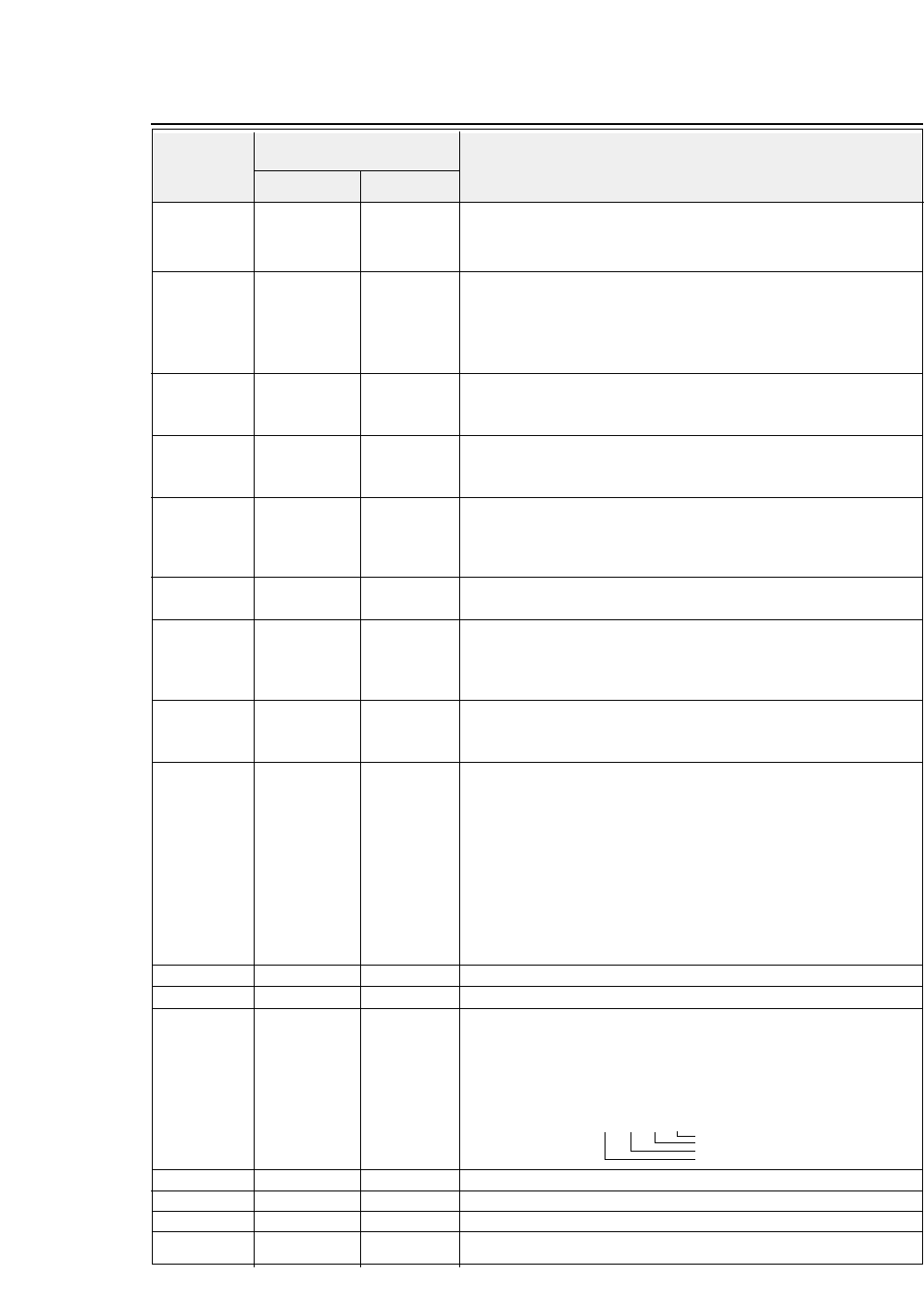
ESC * c (27,42,99,#, (1B,2A,63,#, Set download character code.
# E 69)D 45)H
ESC * c (27,42,99,#, (1B,2A,63,#, Download font control
# F 70)D 46)H Controls download font as follows.
# = 0 (30H) :Delete all download font
# = 3 (33H) :Delete data of current download code.
# = 6 (36H) :Copy ROM font to download font.
ESC * p (27,42,112,#, (1B,2A,70,#, Sets Horizontal positioning by dot
# X 88)D 58)H # = 1/180" units :PCL3 or PCL3+
# = 1/360" units : PCL3+D
ESC * p (27,42,112,#,,(1B,2A,70,#, Sets Vertocal positioning by dot
# Y 89)D 59)H # = 1/180" units :PCL3 or PCL3+
# = 1/360" units : PCL3+D
ESC * r (27,42,114,#, (1B,2A,72,#, Sets start raster graphics printing
# A 65)D 41)H Raster graphics printing starts as follows
# = 0(30H) :Prints from the left most printable position
# = 1(31H) :Prints from the current position
ESC * r (27,42,114, (1B,2A,72, Sets terminates rastergraphics printing
B 66)D 42)H Raster graphics printing is terminated.
ESC * r (27,42,114, (1B,2A,72, Model number request (Serial I/F only)
K 75)D 4B)H Model number is requested.
The printer sends back the following answer when this data is
recognized. “2235A 2712CRLF”
ESC * r (27,42,114,#, (1B,2A,72,#, Designates raster graphics width.
# S 83)D 53)H Raster graphics width is defined by dot.
ESC * t (27,42,116,#, (1B,2A,74,#, Designates raster graphics resolution.
# R 82)D 52)H Raster graphics resolution is defined as follows.
When PCL3+ or PCL3+D is selected.
# = 6 , 0 (36H,30H) :60 dpi
# = 9 , 0 (39H,30H) :90 dpi
# = 1 , 8 , 0 (31H,38H,30H) :180 dpi
# = 3 , 6 , 0 (33H,36H,30H) :360 dpi
When PCL3 is selected.
# = 9 , 0 (39H,30H):90 dpi
# = 1 , 8 , 0 (31H,38H,30H) :180 dpi
ESC 9 (27)D (57)D (1B)H (39)H Clear left and right margin.
ESC = (27)D (61)D (1B)H (3D)H Half line feed - Half line feed is executed.
ESC ? (27,63,17)D (1B,3F,11)H Request I/O status (Serial I/O only)
DC1 Printer status is requested.
The printer sends back the following data to the host computer as
the printer status.
ESC E (27)D (69)D (1B)H (45)H Reset - The printer is initialized.
ESC Y (27)D (89)D (1B)H (59)H Designates display function - Display function is set on.
ESC Z (27)D (90)D (1B)H (5A)H Cancels display function - Display function is set off.
ESC z (27)D (122)D (1B)H (7A)H Self test - Self test print is executed for 1 page.
●
HP Software commands
Decimal Hex
Symbol Function
Code
8-24 — 8. Software commands —
MSB LSB
76543210
0000
1/0 1/0 1/0 1/0 Paper out or cover open
Printer busy
ONLINE (always)
I/O DATA error
:1
:1
:0
:1

9-1
— 9. Software setup functions —
1. Setup start command HD+DC1 (1B,7C,60,01,00,11)H
2. Setup end command HD+DC2 (1B,7C,60,01,00,12)H
3. Save disable command HD+DEL (1B,7C,60,01,00,7F)H
If this command is specified between the setup start command and
setup end command, the setting is not saved in the EEPROM
when the setup end terminates the software setup mode. It is
useful when the enlargement, reduction and other functions are
frequently used.
HD = 1BH,7CH,60H,m1,m2
9.
Software setup functions
The commands shown below are valid only when the software setup
function is activated in the setup mode. If the software setup function is
not activated in the setup mode, these commands are processed as normal
data.
Software setup is activated when the setup start command is issued and
deactivated when the setup end command is issued.
When the setup start command is accepted, any other software commands
and print data are ignored until the setup end command is accepted.
If the printer setting is frequently changed by setup commands, use the
save disable command so as not to exceed the allowable number of retries
to write in the EEPROM, which is approximately 100 thousand.
* Commands (1) to (19) are not automatically reset when the setup is
quit after changing the setting.
Command format
( 1B,7C,60, m1,m2, a1,•••,ak )H
SETUP COMMAND
a1 ~ ak:Optional data
DATA NUMBER
= m1 + 256 x m2 [a1 ~ ak]
HEADER(START)
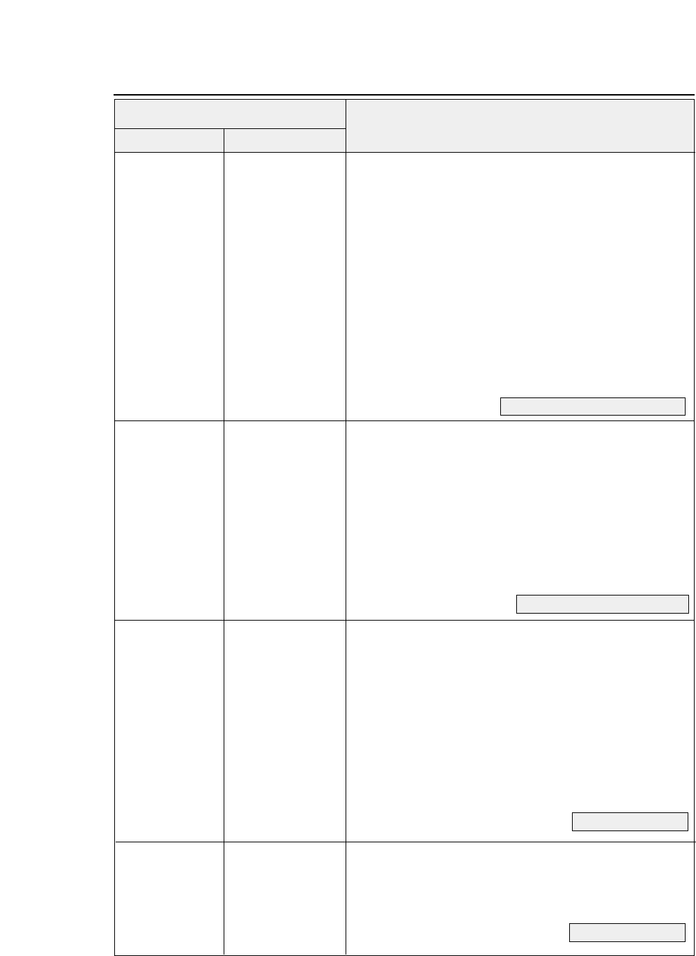
HD + EM + n
(1B,7C,60,02,00,19,n)H
(1) Paper path specification (PAPER PATH key)
(Setup Function #61)
n = 00H
Front loading and rear ejection of fanfold paper
01H
Front loading and front ejection of manually inserted paper
02H
CSF loading and front ejection (Optional)
10H
Front loading and upward ejection of fanfold paper
11H
Front loading and upward ejection of manually inserted paper
12H
Front loading and rear ejection of manually inserted paper
13H
CSF loading and upward ejection (Optional)
4H
Rear loading and front ejection of fanfold paper (Optional)
It is recommended that manual rear ejection not be used
together with another paper path application. Paper path
switching and the paper path switching mechanism are not
guaranteed if there is paper in the paper path switching
mechanism.
HD + F + n
(1B,7C,60,02,00,46,n)H
(2) Paper format selection (PAPER FORM key)
n = 0: Selects format memory 1 (Memo 1)
n = 1: Selects format memory 2 (Memo 2)
n = 2: Selects format memory 3 (Memo 3)
n = 3: Selects format memory 4 (Memo 4)
n = 4: Selects format memory 5 (Memo 5)
n = 5: Selects format memory 6 (Memo 6)
This command selects the format memory to be used for
the currently selected paper path.
HD + x + n
(1B,7C,60,02,00,78,n)H
(3) Character quality setting (QUALITY key)
n=0 LQ (Setup Function #10)
1 DRAFT
2LQ
3 NLQ
4 DRAFT
5 S. D.
6 S. S. D.
7 HQDR
This command specifies the character quality in the
currently selected format memory.
HD + +
(1B,7C,60,01,00,2B)H
(4) TOF position setting (TOF SET key)
This command is valid only when paper is loaded.
It specifies the TOF position of the loaded paper.
●
Command
Hexadecimal
Control code Corresponding setup function
Code
9-2 — 9. Software setup functions —
See pages 1-6, 1-7 and 3-42.
See pages 1-10 and 1-11.
See page 3-17.
See page 2-3.
9-3
— 9. Software setup functions —
●
Command
HD + @
(1B,7C,60,01,00,40)H
(5) Reset (RESET key)
If the printer is reset without saving data, it enters the
condition set when power was turned on.
HD + G + n
(1B,7C,60,02,00,47,n)H
(6) Printing pressure adjustment
(Setup Function #01)
n=0 Normal
1Normal
2Dark 1
3Dark 2
4Auto
This command specifies the printing pressure in the
currently selected format memory.
HD + c + m+n
(1B,7C,60,03,00,63,
(7) Head gap adjustment
(Setup Function #02)
m,n)H
When m = 0,3 Auto mode
n=5 Auto:+5click
::
n=1 Auto:+1click
n=0 Auto:0click
n=255 Auto:-1click
n=254 Auto:-2click
When m = 1,4 Fixed mode
n=25 Fix: +25 click
::
n=1 Fix:+1click
n=0 Fix:0click
n=255 Fix:-1click
n=254 Fix:-2click
::
n=251 Fix:-5click
This command specifies the paper pressure in the currently
selected format memory.
When m=0,1: Paper thickness adjustment is performed
after the printing head moves to the specified position.
When m = 3,4: Paper thickness adjustment is performed
when the command is processed and the printing head does
not move.
HD + p + n1 + n2
(1B,7C,60,03,00,70,
(8) TOF position adjustment
(Setup Function #03)
n1,n2)H 00 ≤n ≤63 n = n1 + 256 x n2
TOF: + n/60"
This command specifies the TOF position in the currently
selected format memory.
Hexadecimal
Control code Corresponding setup function
Code
See page3-8.
See page 3-9.
See page 3-10.
HD + C + m + n
(1B,7C,60,03,00,43,m,n)H
(9) Page length setting
(Setup Function #04)
m = 0
Fanfold paper
m = 1
Cut sheet paper
m = 0
n = 00H 11.0" n = 0AH 6.5"
01H 2.0" 0BH 7.0"
02H 2.5" 0CH 7.5"
03H 3.0" 0DH 8.0"
04H 3.5" 0EH 8.5"
05H 4.0" 0FH 9.0"
06H 4.5" 10H 9.5"
07H 5.0" 11H 10.0"
08H 5.5" 12H 10.5"
09H 6.0" 13H 11.0"
n = 14H 11.5" n = 1BH 15.0"
15H 12.0" 1CH 15.5"
16H 12.5" 1DH 16.0"
17H 13.0" 1EH 16.5"
18H 13.5"
19H 14.0" 20H 12.0"
1AH 14.5"
m = 1
n = 0H A4 PORT
2H A4 PORT n=12H A4 LAND
4H LETTER PORT 14H LETTER LAND
5H LEGAL PORT 15H LEGAL LAND
6H A3 PORT 16H A3 LAND
BH HALF LETTER PORT 1BH HALF LETTER LAND
CH EXECUTIVE PORT 1CH EXECUTIVE LAND
DH
GOVERMENT LETTER PORT
1DH GOVERNMENT LETTER PORT
EH GOVERMENT LEGAL PORT 1EH GOVERNMENT LEGAL PORT
20H A5 PORT 30H A5 LAND
21H LEDGER PORT
22H POST CARD PORT 32H POST CARD LAND
27H COM-10 PORT 37H COM-10 LAND
28H COM-6 PORT 38H COM-6 LAND
29H DL PORT 39H DL LAND
2AH C5 PORT 3AH C5 LAND
2BH F4 PORT 3BH F4 LAND
2CH MONARCH PORT 3CH MONARCH LAND
This command specifies the page length in the currently selected
format memory.
PORT : Portrait
LAND : Landscape
●
Command
Hexadecimal
Control code Corresponding setup function
Code
9-4 — 9. Software setup functions —
See page 3-11.
9-5
— 9. Software setup functions —
●
Command
HD + W + n
(1B,7C,60,02,00,57,n)H
(10) Width of fanfold paper
(Setup Function #05)
n=0 15
inches
110
inches
25
inches
4 12
inches
This command is valid when m = 0 or fanfold paper is
specified in the page length setting (9) above.
This command specifies the paper width in the currently
selected format memory.
HD + T + 00H + n
(1B,7C,60,03,00,54,
(11) Top margin
(Setup Function #06)
00, n)H 00 ≤n ≤15
(In units of 6 lpi)
This command specifies the top margin in the currently
selected format memory.
HD + N + n
(1B,7C,60,02,00,4E,n)H
(12) Bottom margin
(Setup Function #07)
00 ≤n ≤15
(In units of 6 lpi)
The perforation is not skipped when n=0. This command
specifies the bottom margin in the currently selected format
memory.
HD + Q + ml + mr
(1B,7C,60,03,00,51,
(13) Right and left margin
(Setup Function #08, #09)
ml,mr)H
00 ≤ml ≤63
Left margin
00 ≤mr ≤63
Right margin
(In units of 10 cpi)
This command specifies the right and left margins in the
currently selected format memory.
Hexadecimal
Control code Corresponding setup function
Code
See page 3-12.
See page 3-13.
See page 3-14.
See pages 3-15 and 3-16.
HD + k + n
(1B,7C,60,02,00,6B,n)H
(14) Character font selection
(Setup Function #11)
n = 00H ROMAN
01H ROMAN
02H SANS SERIF
03H COURIER
04H PRESTIGE
05H SCRIPT
06H OCR-B
07H OCR-A
08H LETTER GOTHIC
09H ORATOR
0AH ORATOR-S
This command specifies the font in the currently selected
format memory.
HD + P + n (1B,7C,60,02,00,50,n)H
(15) Character pitch selection
(Setup Function #12)
n=0 10 CPI
1 10 CPI
2 12 CPI
3 15 CPI
4 17.1 CPI
5 20 CPI
6 24 CPI
7 PROPORTIONAL
9 16.7 CPI
This command specifies the font in the currently selected
format memory.
HD + 3 + n
(1B,7C,60,02,00,33,n)H
(16) Line feed pitch setting
(Setup Function #13)
n=0 6 LPI
1 8 LPI
2 9 LPI
3 3 LPI
4 4 LPI
This command specifies the font in the currently selected
format memory.
●
Command
Hexadecimal
Control code Corresponding setup function
Code
9-6 — 9. Software setup functions —
See page 3-18.
See page 3-19.
See page 3-20.
9-7
— 9. Software setup functions —
●
Command
HD + SI + n
(1B,7C,60,02,00,0F,n)H
(17) Zoom in/out
(Setup Function #14)
n=00H 100% n=10H 200% n=1AH 1200%
01H 91%
02H 83% n=12H 400% n=1CH 1400%
03H 79%
04H 66% n=14H 600% n=1EH 1600%
0AH 116% n=16H 800%
0BH 120%
0CH 141% n=18H 1000%
This command specifies the zoom in/out in the currently
selected format memory.
HD + 4 + n
(1B,7C,60,02,00,34,n)H
(18) Paper fastener
(Setup Function #15)
n=0 NO
1 YES
This command specifies the paper fastener mode in the
currently selected format memory.
HD + ? + n
(1B,7C,60,02,00,3F,n)H
(19) Perforation head-up
(Setup Function #16)
n=0 NO
1YES
This command specifies the perforation head-up mode in
the currently selected format memory.
HD + Z + n
(1B,7C,60,02,00,5A,n)H
(20) Fanfold feed
(Setup Function #17)
n=0 FRICTION : NO
1 FRICTION : YES
This command specifies the fanfold feed in the currently
selected format memory.
Hexadecimal
Control code Corresponding setup function
Code
See page 3-21.
See page 3-22.
See page 3-22.
See page 3-23.
●
Command
Hexadecimal
Control code Corresponding setup function
Code
9-8 — 9. Software setup functions —
HD + M + 01H + n
(1B,7C,60,03,00,4D,
(21) Saving data in format memory
(Setup Function #19)
01,n)H n=0
Saves data in format memory 1.
1
Saves data in format memory 2.
2
Saves data in format memory 3.
3
Saves data in format memory 4.
4
Saves data in format memory 5.
5
Saves data in format memory 6.
This command saves data in the currently selected format
memory into specified memory.
HD + M + 02H + n
(1B,7C,60,03,00,4D,
(22) Loading data from format memory
(Setup Function #20)
02,n)H n=0
Loads from format memory 1.
1
Loads from format memory 2.
2
Loads from format memory 3.
3
Loads from format memory 4.
4
Loads from format memory 5.
5
Loads from format memory 6.
This command loads data from the specified memory into
the currently selected format memory.
HD + E + n
(1B,7C,60,02,00,45,n)H
(23) Emulation selection
(Setup Function #20)
n=00H EPSON
01H IBM
02 HP
See page 3-24.
See page 3-25.
See page 3-24.
9-9
— 9. Software setup functions —
●
Command
Hexadecimal
Control code Corresponding setup function
Code
HD + t + m + n
(1B,7C,60,03,00,74,
(24) Character table selection
m,n)H (Setup Function #21, #22, #23, #51)
m = 00H EPSON
01H IBM
03H HP (PRIMARY FONT)
04H HP (SECONDARY FONT)
[m=00H: EPSON] [m=01H: IBM]
n = 0
Italic
n =0
Set 1
1
Code page
1
Set 2
2
Download
3
Code page
[m=03H: HP (PRIMARY FONT)]
n = 00
ROMAN-8 (8U)
01
CODE PG CODE PAGE
02
PC-8D/N PC-8
DENMARK/NORWAY(11U)
03
ECMA ECMA LATIN 1
(ISO 8859-1, ON)
04
LEGAL (HP SET, 1U)
05
SWEDEN1 (ISO-10, OS)
06
SWEDEN2 (ISO-11, 3S)
07
SPAIN (ISO-17, 2S)
08
FRANCE (ISO-69, 1F)
09
GERMAN (ISO-21, 1G)
0A
U.K. (ISO-4, 1E)
0B
PORTU PORTUGAL (ISO-16,4S)
0C
NORWAY1 (ISO-60, 4S)
0D
NORWAY2(ISO-61, 1D)
0E
IRV (ISO-2, 2U)
0F
ITALY (ISO-15, 0I)
10
FRANC2 FRACE 2 (ISO-25, OF)
11
GERMN2 GERMAN 2 (HP SET, OG)
12
SPAIN2 (ISO-85, 0G)
13
SPAIN3 (HP-SET, 1S)
14
JAPAN (ISO-14, 0K)
15
PORTU2 PORTUGAL (ISO-84, 5S)
[m=04H: HP (SECONDARY FONT)]
n = 00
LINE-DRAW (0L)
01
MATH-7 (0M)
See pages 3-25, 3-26 and 3-41.
●
Command
Control code Corresponding setup function
Code
9-10 — 9. Software setup functions —
HD + R + n
(1B,7C,60,02,00,52,n)H
(25) National font selection (EPSON)
(Setup Function #24)
n = 0H
USA
8H
Japan
1H
France
9H
Norway
2H
Germany
AH
Denmark2
3H
U.K.
BH
Spain2
4H
Denmark
CH
Latin America
5H
Sweden
DH
Korea
6H
Italy
EH
Turkey
7H
Spain
FH
Legal
HD + i + n
(1B,7C,60,02,00,69,n)H
(26) Code page selection
(Setup Function #25)
n = 0H 437
(USA)
1H 850
(Multilingual)
3H 860
(Portuguese)
4H 863
(Canadian French)
5H 865
(Nordic)
6H 857
(Turkish)
7H 858
8H 861
9H BRASCII
AH ABICOMP
20H ISO 8859-1
HD + Y + n
(1B,7C,60,02,00,59,n)H
(27) Alternate graphics mode (AGM) (IBM)
(Setup Function #26)
n = 0
Invalid
1
Valid
HD + 5 + n
(1B,7C,60,02,00,35,n)H
(28) CR code function
(Setup Function #27)
n = 0 CR only
1 CR + LF
2 AUTOFEED
HD + 6 + n
(1B,7C,60,02,00,36,n)H
(29) LF code function
(Setup Function #28)
n = 0 LF only
1 CR + LF
HD + 1 + n (
1B,7C,60,02,00,31,n)H
(30) Accent character
(Setup Function #29)
n = 0
Simple (Resident Font)
1
Comp. (2 Pass Print)
See page 3-29.
See page 3-27.
See page 3-28.
See page 3-28.
See page 3-30.
See page 3-29.
Hexadecimal
9-11
— 9. Software setup functions —
●
Command
Control code Corresponding setup function
Code Hexadecimal
HD + 0 + n
(1B,7C,60,02,00,30,n)H
(31) Zero font style
(Setup Function #30)
n = 0
No-slashed
"0"
1
Slashed
"0"
HD + w + n
(1B,7C,60,02,00,77,n)H
(32) Horizontal tab interval
(Setup Function #31)
n =0 2
characters
14
characters
26
characters
38
characters
410
characters
512
characters
HD + > + a + n
(1B,7C,60,03,00,3E,
(33) Page length lock
(Setup Function #32)
61, n)H n =0
NO
1
YES
HD + > + b + n
(1B,7C,60,03,00,3E,
(34) Font lock
(Setup Function #33)
62, n)H n =0
NO
1
YES
HD + > + c + n
(1B,7C,60,03,00,3E,
(35) Character pitch lock
(Setup Function #34)
63, n)H n =0
NO
1
YES
HD + > + d + n
(1B,7C,60,03,00,3E,
(33) Character quality lock
(Setup Function #35)
64, n)H n =0
NO
1
YES
HD + > + f + n
(1B,7C,60,03,00,3E,
(36) Character table lock
(Setup Function #36)
66, n)H n =0
NO
1
YES
HD + ] + m + n
(1B,7C,60,03,00,5D,
(37) Validity of bar code and enlarged character
6D, n)H (Setup Function #40)
n=0
Mode 2
1
Ignored
2
Mode 1
See page 3-30.
See page 3-31.
See page 3-31.
See page 3-32.
See page 3-32.
See page 3-33.
See page 3-33.
See page 3-36.
●
Command
Control code Corresponding setup function
Code
9-12 — 9. Software setup functions —
Hexadecimal
HD + ] + n + n
(1B,7C,60,03,00,5D,
(38) Bar code type
(Setup Function #41)
6E,n)H
n=0H
INDSTRAL-2.5
7H
CODE128
1H
INTRLVD-25
8H
EAN-8
2H
MATRIX-25
9H
EAN-13
3H
CODABAR
AH
UPC-A
4H
CODE11
BH
UPC-E
5H
CODE39
CH
POSTNET
6H
CODE93
DH
ELENENT
HD + ] + x + n
(1B,7C,60,03,00,5D,
(39) Bar code size
(Setup Function #42)
78,n)H
n= 0 1
1 1.5
22
3 2.5
HD + ] + X + n
(1B,7C,60,03,00,5D,
(40) Enlarged character size
(Setup Function #43)
58,n)H
n= 0 1
12
24
38
4 12
516
624
732
HD + A + n
(1B,7C,60,02,00,41,n)H
(41) Software setup
(Setup Function #44)
n=0 Valid
1 Ignored 1
2 Ignored 2
The setup command cannot change the ignored setting to
the valid setting. The command becomes valid after the setup
command mode is quit.
See page 3-37.
See page 3-39.
See page 3-39.
See page 3-40.
9-13
— 9. Software setup functions —
●
Command
Control code Corresponding setup function
Code Hexadecimal
HD + < + e + n
(1B,7C,60,03,00,3D,
(42) PCL mode (HP)
(Setup Function #50)
65,n)H
n=0
PCL3+
1
PCL
2
PCL3+D
HD + o + m + n
(1B,7C,60,03,00,6F,
(43) Setting option
(Setup Function #60)
m,n)H
m=0
: CSF
n =0
: No CSF
1
: CSF used (with no rear tractor)
m=0
: Rear tractor
n =0
: No rear tractor
1
: Rear tractor used (with no CSF)
The CSF and rear tractor cannot be used together.
m=2
: Skew detection
(Setup Function #64)
n =0
: NO (No detection)
1
: YES (Detection)
m=3
: Paper jam detection
(Setup Function #65)
n =0
: NO (No detection)
1
: YES (Detection)
HD + S + n
(1B,7C,60,02,00,53,
(44) Automatic scrolling
(Setup Function #62)
n)H n=0
No scroll
1
0.5 second
2
1 second
3
5 seconds
4
10 seconds
5
15 seconds
HD + 8 + n
(1B,7C,60,02,00,38,n)H
(45) Out-of-paper detection
(Setup Function #63)
n=0 No (No detection)
1 Yes (Detection)
HD + f + n
(1B,7C,60,02,00,66,n)H
(46) Line feed speed
(Setup Function #66)
n=0 Normal
1 1/2
2 1/3
See page 3-40.
See page 3-41.
See page 3-43.
See page 3-44.
See page 3-42.
See page 3-43.
See page 3-44.
●
Command
Control code Corresponding setup function
9-14 — 9. Software setup functions —
Code Hexadecimal
HD + I + p + n
(1B,7C,60,03,00,49,
(47) Interface
(Setup Function #70)
70,n)H
n = 0
Parallel
1
Serial
2
Auto
This setting becomes valid after the setup command
mode is terminated.
HD + I + 0 + DC0 + n
(1B,7C,60,04,00,49,
(48) Printer select command
(Setup Function #71)
30,10,n)H
n = 0
Valid
1
Invalid
2
SLCT IN signal
This setting becomes valid after the setup command
mode is terminated.
HD + I + 1 + 0 + n
(1B,7C,60,04,00,49,
(49) Parity bit
(SERIAL I/F) (Setup Function #72)
31,30,n)H
n = 0
None
1
Even
2
Odd
This setting becomes valid after the setup command
mode is terminated.
HD + I + 1 + 1 + n
(1B,7C,60,04,00,49,
(50) Data length
(SERIAL I/F) (Setup Function #73)
31,31,n)H
n = 0
8 bits
1
7 bits
This setting becomes valid after the setup command
mode is terminated.
HD + I + 1 + 2 + n
(1B,7C,60,04,00,49,
(51) Stop bit
(SERIAL I/F) (Setup Function #74)
31,32,n)H
n = 0
1 bit
1
2 bits
This setting becomes valid after the setup command
mode is terminated.
See page 3-46.
See page 3-47.
See page 3-47.
See page 3-48.
See page 3-48.
9-15
— 9. Software setup functions —
●
Command
Control code Corresponding setup function
Code Hexadecimal
HD + I + 1 + 3 + n
(1B,7C,60,04,00,49,
(52) Protocol
(SERIAL I/F) (Setup Function #75)
31,33,n)H
n = 0 DTR
1 X-ON/X-OFF 1
2 X-ON/X-OFF 2
3 ETX/ACK
This setting becomes valid after the setup command mode
is terminated.
HD + I + 1 + 4 + n
(1B,7C,60,04,00,49,
(53) Baud rate
(SERIAL I/F) (Setup Function #76)
31,34,n)H
n = 0 38400 BPS
1 19200 BPS
2 9600 BPS
3 4800 BPS
4 2400 BPS
5 1200 BPS
6 600 BPS
7 300 BPS
This setting becomes valid after the setup command mode
is terminated.
HD + I + 1 + 5 + n
(1B,7C,60,04,00,49,
(54) Operation in case of serial error
(SERIAL I/F)
31,35,n)H (Setup Function #77)
n = 0
Print "❈"
1
Ignored
This setting becomes valid after the setup command mode
is terminated.
HD + I + 1 + DC0 + n
(1B,7C,60,04,00,49,
(55) CTS signal
(SERIAL I/F) (Setup Function #78)
31,10,n)H
n = 0
YES
(ENABLE)
1
NO
This setting becomes valid after the setup command mode
is terminated.
See page 3-49.
See page 3-49.
See page 3-50.
See page 3-50.
●
Command
Control code Corresponding setup function
Code
9-16 — 9. Software setup functions —
Hexadecimal
HD + I + 1 + DC1 + n
(1B,7C,60,04,00,49,
(56) CD signal
(SERIAL I/F) (Setup Function #79)
31,11,n)H
n = 0
YES
(ENABLE)
1
NO
This setting becomes valid after the setup command mode
is terminated.
HD + I + 1 + DC2 + n
(1B,7C,60,04,00,49,
(57) DSR signal
(SERIAL I/F) (Setup Function #80)
31,12,n)H
n = 0
YES
(ENABLE)
1
NO
This setting becomes valid after the setup command mode
is terminated.
HD + I + b + n
(1B,7C,60,03,00,49,
(58) Input buffer size
(Setup Function #81)
62,n)H
n = 0 64K byte
1 8K byte
2 128 byte
This setting becomes valid after the setup command mode
is terminated.
HD + I + 0 + 0 + n
(1B,7C,60,04,00,49,
(59) BUSY/ACK signal timing
(PARALLEL I/F)
30,30,n)H (Setup Function #82)
n = 0
Type 3
1
Type 2
2
Type 1
This setting becomes valid after the setup command mode
is terminated.
HD + I + 0 + 1 + n
(1B,7C,60,04,00,49,
(60) Input data latch timing
(PARALLEL I/F)
30,31,n)H (Setup Function #83)
n = 0
Type F.
1
Type R.
This setting becomes valid after the setup command mode
is terminated.
See page 3-51.
See page 3-51.
See page 3-52.
See page 3-53.
See page 3-53.
9-17
— 9. Software setup functions —
●
Command
Control code Corresponding setup function
Code Hexadecimal
HD + I + 0 + 3 + n (1B,7C,60,04,00,49,
(61) Error status signal output
(Setup Function #84)
30, 33,n)H
n = 0
YES
1
NO
HD + U + n
(1B,7C,60,02,00,55,n)H
(62) Printing direction
(Setup Function #90)
n = 0
Pre-direction
1
Pre-direction
2
Uni-direction
3
Bi-direction
HD + z + n
(1B,7C,60,02,00,7A,n)H
(63) Display language on LCD
(Setup Function #91)
n = 0
ENGLISH
1
DEUTSCH
2
FRANCAIS
3
ESPANOL
4
ITALIANO
HD + > + g + n
(1B,7C,60,03,00,3E,
(64) Locking panel keys other than RESET and
67, n)H
ONLINE keys in the online state
(Setup Function #92)
n = 0
NO
1
YES
HD + > + e + n
(1B,7C,60,03,00,3E,
(65) RESET key lock in the online state
65, n)H (Setup Function #93)
n = 0
NO
1
YES
HD + SP + n1 + n2 (1B,7C,60,03,00,20,
(66) Print Head Position
n1, n2)H
n = n1
+
n2 x 256
Specifies the print head position in units of 1/360 inch
from the leftmost printable position.
The print head moves at the time that this command is
processed.
See page 3-54.
See page 3-55.
See page 3-55.
See page 3-56.
See page 3-56.
HD + q + n (1B,7C,60,02,00,71,n)H
(67) Paper Quality
(Setup Function #18)
n = 0
GOOD
1
NO GOOD
HD + 2 + n (1B,7C,60,02,00,32,n)H
(68) FF CODE AT TOF
(Setup Function #37)
n = 0
NO
1
YES
HD + # + n (1B,7C,60,02,00,23,n)H
(69) Graphic Quality
(Setup Function #38)
n = 0
MODE 0
1
MODE 1
2
MODE 2
HD + S + FF + n (1B,7C,60,03,00,53,
(70) Auto scroll position
(Setup Function #67)
FF,n)H
n = 0
ANY POS
1
TOF ONLT
HD + e + n (1B,7C,60,02,00,65,n)H
(71) Sleep mode
(Setup Function #94)
n = 0
YES
1
NO
●
Command
Hexadecimal
Control code Corresponding setup function
Code
9-18 — 9. Software setup functions —
See page 3-23.
See page 3-34.
See page 3-35.
See page 3-45.
See page 3-57.

10-1
— 10. Specifications —
Printing Method
Serial impact dot matrix
Print Head
24-pin movable (Parallel/Staggered orientation)
Emulation
EPSON LQ-2550 TM
IBM 2391 TM
Hewlett Packard Rugged Writer 480 TM (PCL3) TM
Bar code function
Enlarged character mode
Print Mode 10 cpi, 12 cpi, 15 cpi, 16.7 cpi, 17.1 cpi, 20 cpi, 24 cpi
Proportional printing
1/2 Proportional printing
Emphasized mode
Double striking mode
Double-width mode
Double-hight mode
Superscript & subscript mode
Italic mode
Download Character
EPSON
:
128 characters
IBM :
32 KB
HP
:
128 characters (PCL3), 255 characters (PCL3+, PCL3+D)
Character Table
EPSON
:
Italic set
Extended graphic set
IBM :
Code Page 437 (USA), 850 (Multilingual),
857 (Turkish), 858, 860 (Portuguese), 861 (Icelandic),
863 (Canadian French), 865 (Nordic), ISO-8859-1
BRASCII, ABICOMP
(Code Page can be used in the EPSON or HP mode.)
HP
:
ROMAN-8 (8U), PC-8 (10U), PC-850 (12U),
ECMA 94, LATIN 1(ISO-8859-1,0N), PC-8 DENMARK/NORWAY (11U),
LINE-DRAW (0L,0B), MATH 7(0A,0M), ROMAN-EXTENSION (0E),
SWEDEN 2 (ISO-10,3S), SWEDEN (ISO-11,0S),
UK (ISO-4,1E), FRANCE 2 (ISO-25,0F), FRANCE (ISO-69,1F),
GERMAN 2 (0G), GERMAN (ISO-21,1G),ITALY (ISO-15,0I),
SPAIN 3 (1S), SPAIN (ISO-17,2S), SPAIN 2 (ISO-85,6S)
PORTUGAL (ISO-16,4S), PORTUGAL (ISO-84,5S), IRV (ISO-2,2U),
JAPAN (ISO-14,0K), ASCII (ISO-6,0U), LEGAL (1U)
Graphic Printing
EPSON
:
11 types
IBM :
12 types
❈Horizontally adjacent dots can not be printed.
HP
:
4 raster graphic 60dpi, 90dpi, 180dpi, 360dpi
10.
Specifications
Printing specifications
Max. dots Dots/inch Vertical dots
816 60 8/24
1088 80 8
1224 90 8/24
1632 120 8/24
1632
❈
120 8
2448 180 24
3264
❈
240 8
4896
❈
360 24
4896
❈
360 48(IBM mode)
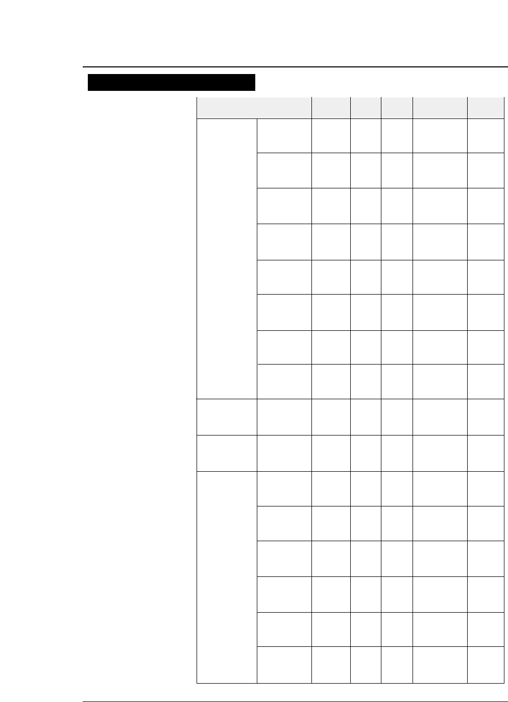
Normal 1/120 12
×
12 603
10cpi Dark 1 1/120 136 12
×
12 474
Dark 2 1/180 12
×
18 316
Normal 569
12cpi Dark 1 1/144 163 12
×
12 432
Dark 2 432
Normal 712
15cpi Dark 1 1/180 204 12
×
12 473
Dark 2 473
Normal 526
Draft 16.7cpi Dark 1 1/240 227 12
×
12(+2.4) 399
Dark 2 399
Normal 540
17cpi Dark 1 1/240 233 12
×
12(+2) 411
Dark 2 411
Normal 631
20cpi Dark 1 1/240 272 12
×
12 481
Dark 2 481
Normal 577
24cpi Dark 1 1/360 326 12
×
12(+3) 379
Dark 2 379
Normal
Proportional Dark 1 1/180 ---- 12
×
N ----
(IBM,HP) Dark 2
Normal 723
Speed Draft 12cpi Dark 1 1/120 163 12
×
8(+2) 569
(SD) Dark 2 569
Normal 904
S.Speed Draft 15cpi Dark 1 1/120 204 12
×
8 712
(SSD) Dark 2 712
Normal 180
10cpi Dark 1 1/360 136 24
×
36 79
Dark 2 59
Normal 216
12cpi Dark 1 1/360 163 24
×
30 95
Dark 2 71
Letter Normal 270
Quality 15cpi Dark 1 1/360 204 24
×
24 118
(LQ) (EPSON) Dark 2 89
Normal 237
15cpi Dark 1 1/720 204 24
×
36(+12) 118
(IBM,HP) Dark 2 89
Normal 263
16.7cpi Dark 1 1/720 227 24
×
36(+7) 131
Dark 2 98
Normal 270
17cpi Dark 1 1/720 233 24
×
36(+6) 135
Dark 2 102
Print mode Mulipart Dot pitch Max. No. Character Structure Print speed
mode (inch) of Col. (V ×H) (cps)
10-2
●
Print mode specifications
— 10. Specifications —
Print mode specifications
( ): Additional space
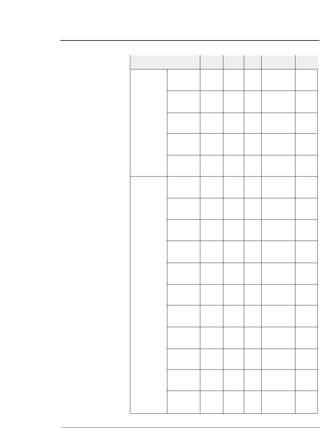
10-3
— 10. Specifications —
●
Print mode specifications
Normal 315
20cpi Dark 1 1/720 272 24
×
30(+6) 158
Dark 2 119
Normal 380
24cpi Dark 1 1/720 326 24
×
24(+6) 189
(EPSON) Dark 2 142
Letter Normal 380
Quality 24cpi Dark 1 1/720 326 24
×
30 189
(LQ) (IBM,HP) Dark 2 142
Normal
Proportional
Dark 1 1/360 ---- 24 ×N ----
Dark 2
Normal
1/2 Prop.
Dark 1 1/720 ---- 24 ×N ----
(EPSON) Dark 2
Normal 240
10cpi Dark 1 1/360 136 24
×
36 158
Dark 2 158
Normal 289
12cpi Dark 1 1/360 163 24
×
30 189
Dark 2 189
Normal 361
15cpi Dark 1 1/360 204 16
×
24 237
(EPSON) Dark 2 237
Normal 237
15cpi Dark 1 1/720 204 24
×
36(+12) 158
(IBM,HP) Dark 2 158
Normal 263
NLQ 16,7cpi Dark 1 1/720 227 24
×
36(+7) 175
Dark 2 175
Normal 270
17cpi Dark 1 1/720 233 24
×
36(+6) 180
Dark 2 180
Normal 316
20cpi Dark 1 1/720 272 24
×
30(+6) 210
Dark 2 210
Normal 379
24cpi Dark 1 1/720 326 16
×
24(+6) 253
(EPSON) Dark 2 253
Normal 379
24cpi Dark 1 1/720 326 24
×
30 253
(IBM,HP) Dark 2 253
Normal
Proportional
Dark 1 1/360 ---- 24 ×N ----
Dark 2
Normal
1/2 Prop.
Dark 1 1/720 ---- 24 ×N ----
(EPSON) Dark 2
Print mode Mulipart Dot pitch Max. No. Character Structure Print speed
mode (inch) of Col. (V ×H) (cps)
( ): Additional space
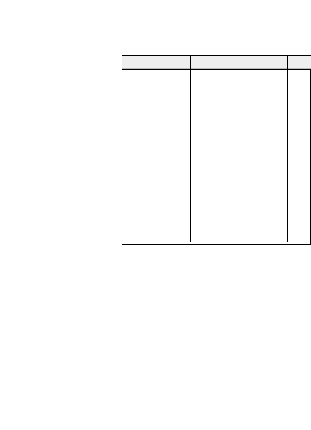
Normal 360
10cpi Dark 1 1/120 136 24
×
36 240
Dark 2 240
Normal 289
12cpi Dark 1 1/144 163 24
×
12(+3) 216
Dark 2 216
Normal 361
15cpi Dark 1 1/180 204 24
×
12 237
Dark 2 237
Normal 263
HQDR 16.7cpi Dark 1 1/240 227 24
×
12(+2.3) 175
Dark 2 175
Normal 270
17cpi Dark 1 1/240 233 24
×
12(+2) 180
Dark 2 180
Normal 316
20cpi Dark 1 1/240 272 24
×
12 210
Dark 2 210
Normal 379
24cpi Dark 1 1/240 326 24
×
12(+3) 253
Dark 2 253
Normal
Proportional
Dark 1 1/144 ---- 24 ×N ----
(IBM,HP) Dark 2
Print mode Mulipart Dot pitch Max. No. Character structure Print speed
mode (inch) of Col. (V ×H) (cps)
10-4 — 10. Specifications —
●
Print mode specifications
( ): Additional space
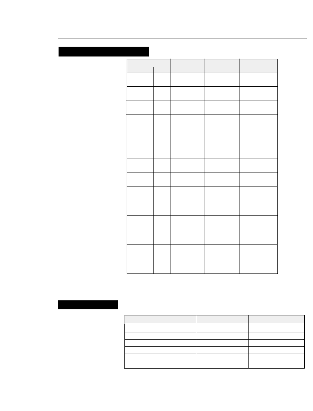
Draft (10cpi) 132 206 LPM
LQ pica (10cpi) 132 76 LPM
NLQ (10cpi) 132 100 LPM
HQDR (10cpi) 132 135 LPM
S. D. (12cpi) 132 230 LPM
S. S. D. (15cpi) 132 270 LPM
10-5
— 10. Specifications —
60dpi 8/24 1/60inch Normal 31.6
Dark 1/2 24.0
80dpi 8 1/80inch Normal 24.0
Dark 1/2 18.0
90dpi 8/24 1/90inch Normal 18.0
Dark 1/2 15.8
120dpi 8/24 1/120inch Normal 18.0
Dark 1/2 10.5
120dpi 8/24 1/60inch Normal 36.0
(High speed 1,2)
Dark 1/2 24.0
120dpi 8 1/60inch Normal 31.6
Dark 1/2 24.0
180dpi 24 1/120inch Normal 18.0
Dark 1/2 10.5
180dpi 24 1/90inch Normal 24.0
(High speed 1) Dark 1/2 18.0
180dpi 24 1/60inch Normal 36.0
(High speed 2) Dark 1/2 24.0
240dpi 8 1/120inch Normal 18.0
Dark 1/2 10.5
240dpi 8 1/60inch Normal 36.0
(High speed 1,2)
Dark 1/2 24.0
360dpi 24 1/120inch Normal 18.0
Dark 1/2 10.5
360dpi 24 1/90inch Normal 24.0
(High speed 1) Dark 1/2 18.0
360dpi 24 1/60inch Normal 36.0
(High speed 2) Dark 1/2 24.0
●
specifications
Graphic type Horizontal Print Print speed
Density Pins dot pitch pitch inch/sec
Print Mode Columns Throughput
Throughput
Graphic printing specifications
NOTE : High speed 1, Quality : NLQ
High speed 2, Quality : HQDR, DRAFT, S. D., S. S. D.

10-6 — 10. Specifications —
Major functions
- High-speed printing
- Original plus 8 multipart forms printing
- Bar code printing
- Enlarged character printing
- Zooming IN/OUT
- Built-in skew sensor
- Automatic head adjustment
- Perforation cutting
- Paper parking
- Automatic perforation feeding (Automatic
scroll)
- Dual paper parking (with rear tractor)
- Setup memory setting
- Vertical alignment
- Energy Star
Interfaces
Parallel I/F (Centronics-compatible)
Bidirectional (IEEE1284, Nibble mode)
Serial I/F (RS-232C)
Protocol: DTR, X-ON/X-OFF 1,
X-ON/X-OFF 2, ETX/ACK
Baud rate: 38400, 19200, 9600, 4800,
2400, 1200, 600, 300 (bps)
Data buffer size: 512k byte maximum
●Power supply: AC 120V, 60Hz for USA and Canada
AC 230V, 50Hz for Europe and Asia
●Power consumption: 200 watts (Draft, LQ Self Test)
45 watts (Standby)
14 watts (Sleep mode)
●Optional parts power
source: 5 V, 1.5 A
●Operating temp.: 5 to 40°C [41 to 104°F]
●Operating humidity: 20 to 80% (No condensation)
●MTBF: 10,000 hours (at 25% duty; Not
applicable to print head.)
Dimensions: 630
×395 ×250 mm (W ×D × H)
[24.8 × 15.6 × 9.8 inch]
Weight: Approximately 24 kg [52.9 lbs.]
Available paper sizes
●Fanfold paper Paper width: 3 ~ 16 inches (Front tractor)
3~ 16.5 inches ( Rear tractor)
Paper thickness: 0.08 ~ 0.12 mm
Paper weight: 55 ~ 90 kg
17 ~ 28 lbs
64 ~ 105 g/m2
Paper quality: Wood-free paper
●Fanfold paper Number of sheets: 9 or less (Dark 2)
(multipart forms) Paper thickness: 0.12 ~ 0.59mm
Paper weight: 34 kg original +8
non-carbon equivalent
●Cut sheet paper Paper thickness: 0.08 ~ 0.12 mm
Paper weight: 55 ~ 90 kg
17 ~ 28 lbs
64 ~ 105 g/m2
Paper quality: Wood-free paper
Paper sizes: A3, A4, A5, Letter,
Half letter, Legal
Executive, Ledger,
Government legal,
Government letter, F4
Max. dimensions: 420×432 mm (W×L)
Min. dimensions: 76 ×76 mm (W×L)
●Post card
●Envelope Commercial-6,10
Monarch
DL,C5
Paper loading method
Fanfold paper: Push tractor
Tractor: Front tractor (standard)
Rear tractor (option)
Cut sheet paper Friction type feeding
Manual, CSF (option)
Multipart printing capability (LQ)
Standard mode: Original sheet + 5 sheets
Dark 1 mode: Original sheet + 7 sheets
Dark 2 mode: Original sheet + 8 sheets
These modes are selectable with #1 MULTIPART in
the SETUP MODE.
Line feed speed: 83 lines per second (6 lines/inch)
The line feed speed is selectable with #66 LF
SPEED in the EXTENDED SETUP MODE.
Line feed pitch: 1/360 inch minimum
Option: Rear Tractor
Option: Cut Sheet Feeder
●
specifications
Paper specifications
Other specifications

11.
Character set table
EPSON Italic table
EPSON Extended graphic table
— 11. Character set table — 11-1
H0 123456789ABCDEF
L(0) (16) (32) (48) (64) (80) (96) (112) (128) (144) (160) (176) (192) (208) (224) (240)
0
1
2
3
4
5
6
7
8
9
A
B
C
D
E
F
(15) (31) (47) (63) (79) (95) (111) (127) (143) (159) (175) (191) (207) (223) (239) (255)
H0 123456789ABCDEF
L(0) (16) (32) (48) (64) (80) (96) (112) (128) (144) (160) (176) (192) (208) (224) (240)
0
1
2
3
4
5
6
7
8
9
A
B
C
D
E
F
(15) (31) (47) (63) (79) (95) (111) (127) (143) (159) (175) (191) (207) (223) (239) (255)
Select this character table with ESC 6 and ESC t 1.
Select this character table with ESC t 0.
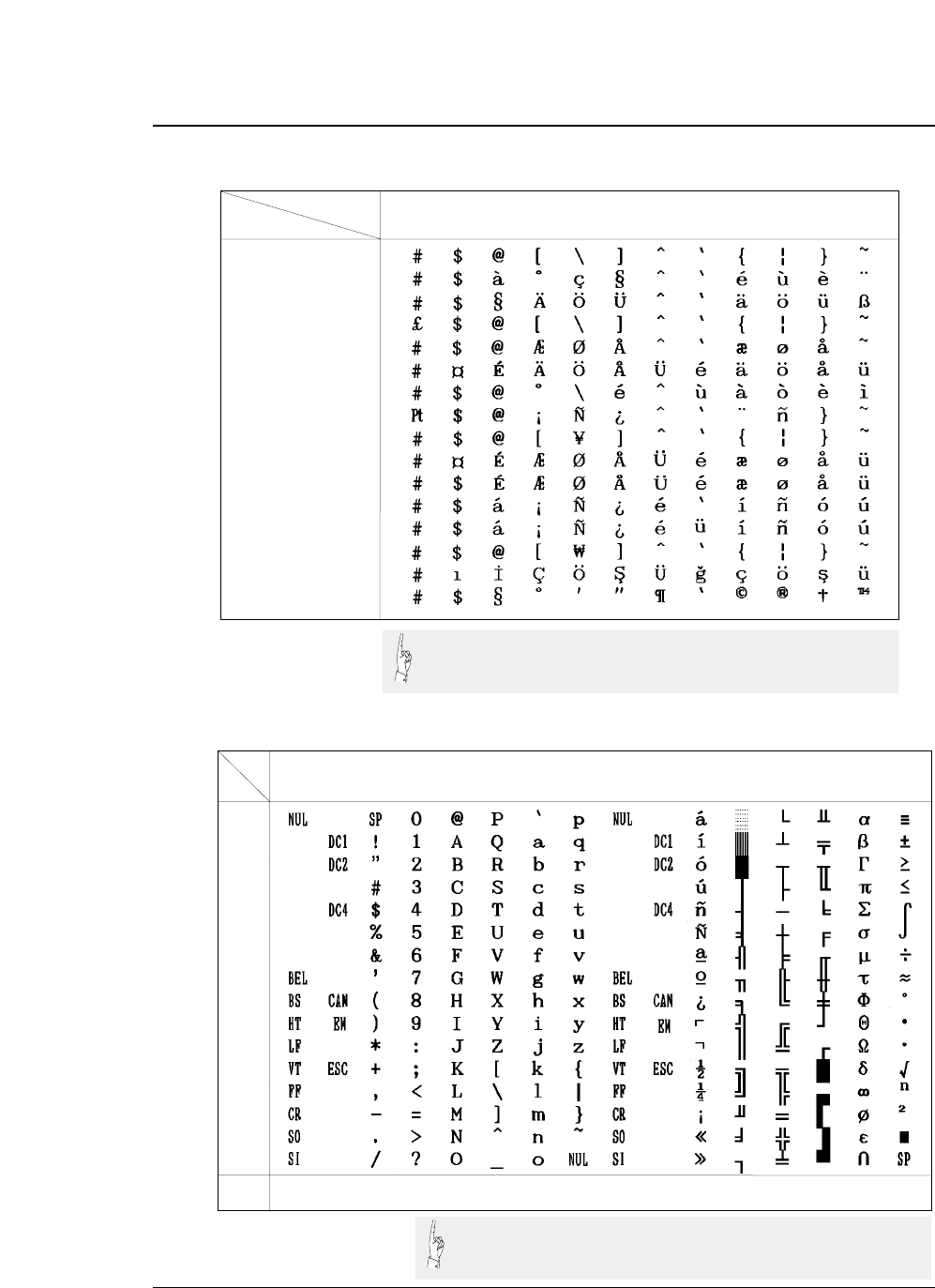
11-2 — 11. Character set table —
EPSON international font table
IBM character set table 1
H0 123456789ABCDEF
L(0) (16) (32) (48) (64) (80) (96) (112) (128) (144) (160) (176) (192) (208) (224) (240)
0
1
2
3
4
5
6
7
8
9
A
B
C
D
E
F
(15) (31) (47) (63) (79) (95) (111) (127) (143) (159) (175) (191) (207) (223) (239) (255)
Country HEX 23 24 40 5B 5C 5D 5E 60 7B 7C 7D 7E
U.S.A
FRANCE
GERMANY
U.K
DENMARK
SWEDEN
ITALY
SPAIN
JAPAN
NORWAY
DENMARK2
SPAIN2
LATIN AMERICA
KOREA
TURKEY
LEGAL
●Character set table
Select this character table with ESC R.
Select this character table with ESC 7.
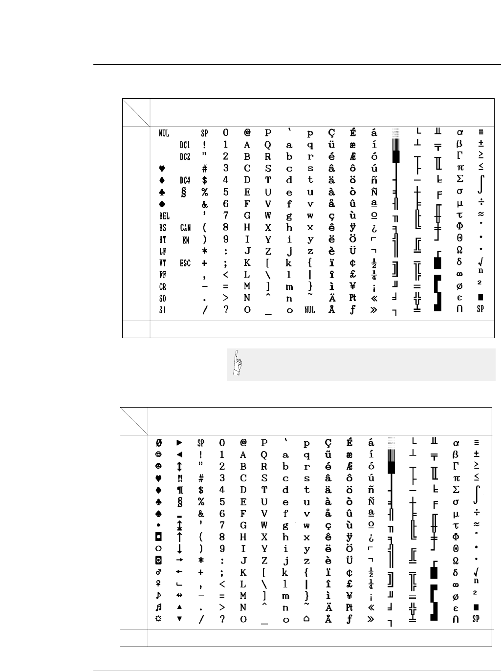
●Character set table
— 11. Character set table — 11-3
IBM character set table 2
IBM all-character set table
H0 123456789ABCDEF
L(0) (16) (32) (48) (64) (80) (96) (112) (128) (144) (160) (176) (192) (208) (224) (240)
0
1
2
3
4
5
6
7
8
9
A
B
C
D
E
F
(15) (31) (47) (63) (79) (95) (111) (127) (143) (159) (175) (191) (207) (223) (239) (255)
Select this character table with ESC 6.
H0 123456789ABCDEF
L(0) (16) (32) (48) (64) (80) (96) (112) (128) (144) (160) (176) (192) (208) (224) (240)
0
1
2
3
4
5
6
7
8
9
A
B
C
D
E
F
(15) (31) (47) (63) (79) (95) (111) (127) (143) (159) (175) (191) (207) (223) (239) (255)
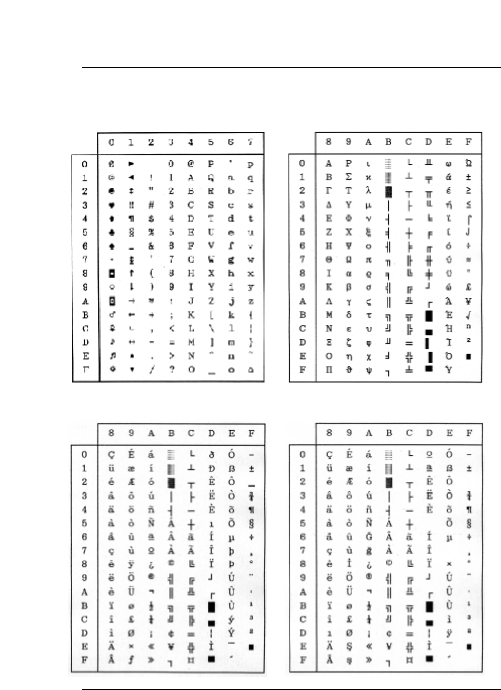
11-4 — 11. Character set table —
Code 00H ~ 7FH (Common) Code page 437 (U.S.A.)
Code page 850 (Multilingual) Code page 857 (Turkish)
●Character set table
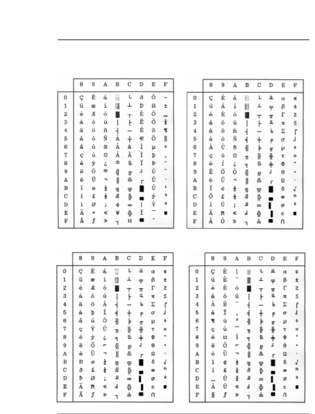
●Character set table
— 11. Character set table — 11-5
Code page 858 (Multilingual-Euro) Code page 860 (Portuguese)
Code page 861 (Icelandic) Code page 863 (Canadian French)
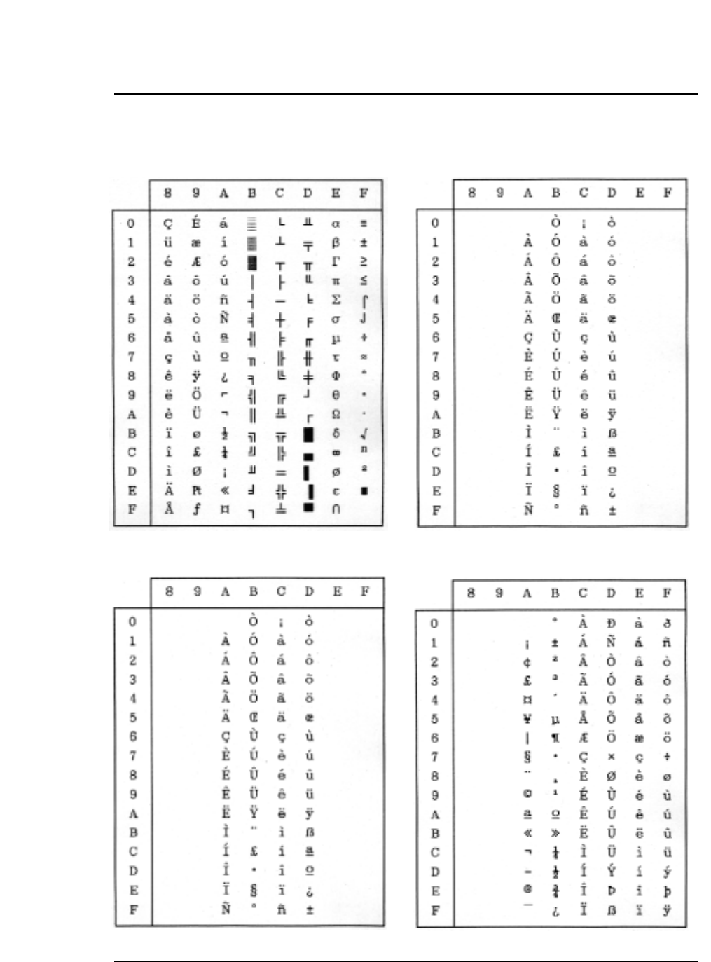
●Character set table
Code page 865 (Nordic) BRASCII
ABICOMP ISO-1 (ISO-8859-1)
11-6 — 11. Character set table —
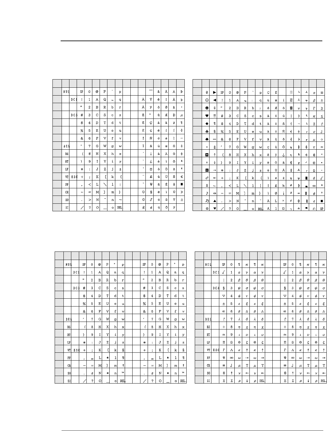
— 11. Character set table — 11-7
HP mode
ROMAN-8 character set PC-8 (Danish / Norwegian) character set
LEGAL character set MATH 7 character set
●Character set table
0
1
2
3
4
5
6
7
8
9
A
B
C
D
E
F
0123456789ABCDEF
L/H
0
1
2
3
4
5
6
7
8
9
A
B
C
D
E
F
0123456789ABCDEF
L/H
0
1
2
3
4
5
6
7
8
9
A
B
C
D
E
F
0123456789ABCDEF
L/H
0
1
2
3
4
5
6
7
8
9
A
B
C
D
E
F
0123456789ABCDEF
L/H
The (00)H-(1F)H and (7F)H normally function as control code.
The character of (A0)H-(FF)H are, respectively, the same as those
of (20)H -(7F)H. The character of (A0)H-(FF)H are, respectively, the same as those
of (20)H -(7F)H.
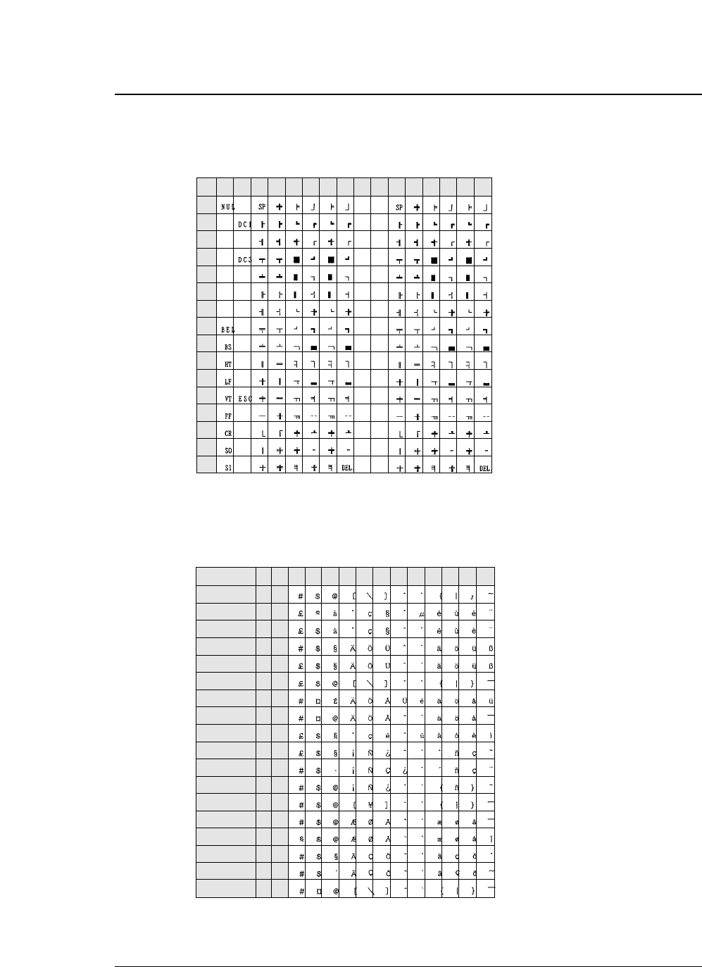
●Character set table
11-8 — 11. Character set table —
0
1
2
3
4
5
6
7
8
9
A
B
C
D
E
F
0123456789ABCDEF
L/H
ASCII
FRANCE
FRANCE 2
GERMANY
GERMANY 2
U.K.
SWEDEN
SWEDEN 2
ITALY
SPAIN
SPAIN 2
SPAIN 3
JAPAN
NORWAY
NORWAY 2
PORTUGAL
PORTUGAL 2
IRV
23 24 40 5B 5C 5E 60 7B 7C 7D 7E
ISO ID
0U
1F
0F
1G
0G
1E
0S
3S
0I
2S
6S
1S
0K
0D
1D
4S
5S
2U
6
69
-
21
-
4
11
10
15
17
85
-
14
60
61
16
84
2
5D
•The character of (A0)H-(FF)H are, respectively, the same as those of (20)H -(7F)H.
•The characters with (20)H-(7F)H codes which are not shown in the International character
set above are the same as those of (20)H -(7F)H in ROMAN-8.
The character of (A0)H-(FF)H are, respectively, the same as those of (20)H -(7F)H.

Symbol
, , , Key............................3-2
A
Accent character.............................................3-30
ALT key ............................................................2-4
Alternate graphics mode (AGM) (IBM) ...........3-28
AUTO FEED signal ................................3-29, 7-3
Automatic scrolling .................................3-42, 4-4
Automatic serial/parallel ................................7-11
B
Bar code function
Code 128 subset transition rule .........5-11
Setting HRI print ...........................5-3, 5-9
Setting HRI font ...................................5-4
Printing density .................................... 5-5
Error processing ................................5-10
Element width ......................................5-3
Guard bar expansion ...........................5-5
Outline of the bar code function ..........5-1
Beginning of sequence ........................5-4
End of sequence .................................5-5
Data processing in the bar code
data sequence ................................5-7
Start and stop characters ....................5-6
Check character ..................................5-4
Bar code data sequence .....................5-5
Bar code rotational angle ....................5-6
Bar code height ..........................3-39, 5-3
Value input mode ................................5-6
Bar code type .............................3-37, 5-2
Buffer size .....................................................3-49
C
Cable Parallel interface ..................................7-1
Serial interface ....................................7-5
Caution ..............................................................iv
Character font ...............................................3-18
Character pitch .............................................3-19
Character table
Selecting character table (EPSON) ...3-26
Selecting character table (IBM) .........3-26
Selecting character table (HP) ..........3-25
Selecting code page ..........................3-28
Selecting national font (EPSON) .......3-27
Selecting secondary
character table (HP) ....................3-41
EPSON italic table ..............................11-1
EPSON extended graphic table .........11-1
EPSON international font table .........11-2
IBM character set table 1 .................11-2
IBM character set table 2 ..................11-3
IBM all-character set table .................11-3
Code page 437 ..................................11-4
Code page 850 ..................................11-4
Code page 857 ..................................11-4
Code page 858 ..................................11-5
Code page 860 ..................................11-4
Code page 861 ..................................11-6
Code page 863 ..................................11-5
Code page 865 ..................................11-5
Code page 858 ..................................11-5
ISO-8859-1 ........................................11-6
Code page BRASCII .........................11-6
Code page ABICOMP .......................11-6
ROMAN-8 ..........................................11-7
PC-8 (Danish/Norwegian) .................11-7
LEGAL ...............................................11-7
MATH 7 .............................................11-7
LINE DRAW ......................................11-8
Internatinal character set (ISO) .........11-8
Components and functions ........................viii, ix
Connecting the printer to the computer
Parallel interface ................................1-28
Serial interface ..................................1-29
Connector
Parallel ................................................7-1
Serial ...................................................7-5
Consumables ..................................................xii
Control panel ..............................................x, 2-1
CR code function ...........................................3-29
Cut sheet paper
Printing area ........................................1-9
Loading (Manual paper feeding) .......1-19
Printing using the CSF ......................1-22
D
Dark .......................................................i, 3-8, 4-2
Default setting .................................................3-6
Dimensions .......................................................vii
Disabled printing area
Top margin .........................................3-13
Bottom margin ....................................3-14
Left margin .........................................3-15
Right margin .......................................3-16
Dual paper packing .......................................1-16
E
EEPROM initialization ....................................4-5
EJECT/LOAD key ...........................................2-3
Enlarged character function
Character pitch ..................................5-23
HMI ....................................................5-21
VMI ...................................................5-22
Setting and canceling underscores ....5-26
INDEX

I
Improving printing capability ............................3-8
Installing ribbon cassette ................................1-2
Interface specifications
Parallel interface ..................................7-1
Serial interface ....................................7-5
K
Key shortcut functions ....................................4-9
L
LF code function ............................................3-29
Line feed pitch ...............................................3-20
Line feed speed .............................................3-44
LINE FEED/REVERSE LF key ........................2-4
Liquid crystal display ..............................1-10, 2-5
Loading date from format memory ...............3-24
Locking panel keys .......................................3-56
Locking reset key ..........................................3-56
M
Major functions .................................................... i
ManualPaper path ....................................1-5, 2-2
Selecting paper path ..................1-7, 3-42
Loading ..............................................1-19
Page length .......................................3-11
Max. No. of column .......................................10-2
MICRO LF/MICRO RLF key ...........................2-4
N
National font (EPSON) ..................................3-27
O
Operating humidity .......................................10-6
Operating temperature .................................10-6
Operational error messages
HEAD PROTECTION ......................... 6-2
PARK ERROR .....................................6-2
PAPER OUT ERROR ..........................6-3
PAPER JAM ERROR ..........................6-3
SKEW ERROR ....................................6-4
FRONT COVER OPEN .......................6-4
PAPER PATH ERROR..........................6-4
H. ADJ: FIX ERROR ...........................6-4
FLAP SWITCHING ERROR..................6-5
JAM. S LEVEL ERR .............................6-5
Options ..............................................................xii
Index
All-character set ...............................5-20
Form feeding .....................................5-18
Line feeding .......................................5-17
Rotational angle ................................5-24
Initializing the enlarged character
mode ...........................................5-18
Setting and canceling the enlarged
character mode ...........................5-22
Selecting an enlarged character font...5-20
Vertical printing position .................... 5-27
Horizontal printing position ................5-26
Setting and canceling enlarged
character smoothing ......................5-25
Cell offset ...........................................5-23
Cell expansion ...................................5-19
Height expansion ...............................5-21
Top offset ...........................................5-25
Back spacing ......................................5-17
Carriage returning ..............................5-18
Arrangement .......................................5-19
Character quality ................................5-24
Width expansion .................................5-26
Print samples ......................................5-28
Enlarging/Reducing print ..............................3-21
ENTER key .....................................................3-2
Executing test printing ....................................4-9
EXIT key .........................................................3-2
F
Factory default setting .....................................3-6
Fanfold paper
Paper path ....................................1-4, 2-2
Selecting paper path ...........1-6, 1-7, 3-42
Printing area ........................................1-8
Loading (Front tractor) .......................1-12
Loading (Rear tractor) .......................1-16
Page length .......................................3-11
Paper width .......................................3-12
Feeding perforation to the cutter
position .............................2-1, 4-3
FORM FEED key .............................................2-4
Functional error massages
CARRIAGE ERROR ............................6-1
FAN ERROR ...................................... 6-1
F.S. ERROR ........................................6-1
T.S. ERROR ........................................6-1
HAI. S. ERROR ...................................6-1
HA. S. ERROR ....................................6-2
HOME S. ERROR ...............................6-2
PLEASE POWER OFF ........................6-2
H
High-speed printing ...............................4-1, 10-2
Horizontal tab ...............................................3-31
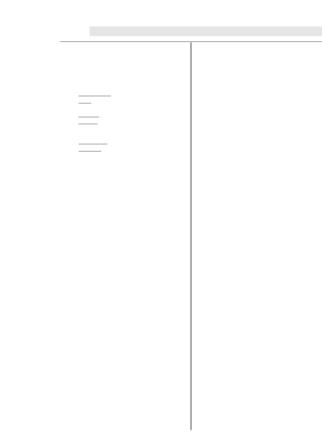
P
Paper ..............................................................1-8
PAPER FORM key .........................................2-4
Paper jam detection ......................................3-44
PAPER PATH key ..........................................2-2
Parallel interface
AUTO FEED signal .............................7-3
ACK signal ..........................................7-4
BUSY signal ........................................7-4
ERROR signal .....................................7-4
INITIAL signal ......................................7-3
PE signal .............................................7-4
SELECT signal ....................................7-4
SELECT IN signal ...............................7-3
STROBE signal ...................................7-3
Data latch timing ................................3-53
Timing chart
Data input .....................................7-2
Initialization ..................................7-2
Power consumption ......................................10-6
Power cord ................................................vi, 1-1
Print head .....................................................viii, ix
Print mode specifications ...............................10-2
Printing area .............................................1-8, 1-9
Printing direction ............................................3-55
Print method ..................................................10-1
Printing out
Smudging paper ...................................6-6
Correcting vertical misalignment .......... 4-6
Printing speed ...............................................i, 4-1
Q
QUALITY key ..................................................2-3
R
RESET key .....................................................2-1
S
S.D. (Speed Draft) ........................................... 4-1
S.S.D. (Super Speed Draft) .............................4-1
Saving data in format memory ......................3-24
Selecting emulation .......................................3-25
Selecting interface .........................................3-46
Selecting paper path .......................................1-6
Setting option .................................................3-41
Setting serial interface
Parity bit ............................................3-47
Data length ........................................3-48
Stop bit ..............................................3-48
Protocol .............................................3-49
Baud rate ...........................................3-49
Serial error .........................................3-50
CTS signal ..................................3-50, 7-6
CIN ....................................3-52, 7-8, 7-11
CD signal .....................................7-7, 3-51
CRN .................................3-52, 7-8, 7-11
DSR signal .................................3-51, 7-6
DTR protocol ..............................3-49, 7-8
DTR signal ...........................................7-7
EXT/ACK protocol .....................3-49, 7-11
RXD signal ..........................................7-6
RTS signal ...........................................7-7
TXD signal ..........................................7-7
SRTS signal .......................................7-7
X-ON/X-OFF (I)/(II) protocol .......3-49, 7-9
Setting the printing start position .....................4-2
Setup modes
Outline .................................................3-1
Key type ..............................................3-2
Factory defaults setting .......................3-6
Setting example ...................................3-3
Saving data in format memory ..........3-24
Printing setup list ................................3-57
Enter/Exit ......................................3-1, 3-3
Loading data from format memory ....3-24
Skew detection .............................................3-43
Software command
EPSON ...............................................8-1
IBM ......................................................8-9
HP .....................................................8-18
Bar code .............................................5-2
Enlarged character function ..............5-16
Software setup ..............................................3-40
Command ............................................9-2
Setup functions ....................................9-1
Specifications ...............................................10-1
T
TEAR OFF key ...............................................2-1
Throughput ...............................................i, 10-5
TOF SET key ...................................................2-3
Top of form (TOF) adjustment ................3-10, 4-2
Troubleshooting ...............................................6-1
U
Unpacking ..................................................... v, vi
Using various types of paper .................1-10, 4-8
W
Weight ...........................................................10-6
Z
Zero font with slash .......................................3-30
Index
BEL (07)D (07)
Activates the printer buzzer.
BS (08)D (08)H
Moves the printing position left by one character
HT (09)D (09)H
Moves the printing position to the following horizontal tab
LF (10)D (0A)H
Single-line feed
VT (11)D (0B)H
Vertical tab
FF (12)D (0C)H
Form feed
CR (13)D (0D)H
Carriage return
SO (14)D (0E)H
Double-width printing on a single line
SI (15)D (0F)H
Specifies condensed mode.
DC1 (17)D (11)H Printer select
DC2 (18)D (12)H
Cancels condensed mode.
DC3 (19)D (13)H
Printer deselect
DC4 (20)D (14)H
Cancels the double-width mode established by the SO command.
CAN (24)D (18)H
Cancel
DEL (127)D (7F)H
Deletes a character
ESC (27)D (1B)H
Escape
ESC SO (27)D(14)D (1B)H (0E)H
Double-width printing on a single line
ESC SI (27)D(15)D (1B)H (0F)H
Specifies condensed mode.
ESC EM (27)D(25)D (1B)H (19)H
Specifies the paper path.
ESC SP (27)D(32)D (1B)H (20)H
Specifies the space between characters.
ESC ! (27)D(33)D (1B)H (21)H
Batch printing mode selection.
ESC # (27)D(35)D (1B)H (23)H
Cancels MSB control.
ESC $ (27)D(36)D (1B)H (24)H
Specifies the absolute printing position.
ESC % (27)D(37)D (1B)H (25)H
Specifies or cancels a downloaded character set
.
ESC & (27)D(38)D (1B)H (26)H
Defines a downloaded character.
ESC
✽
(27)D(42)D (1B)H (2A)H
Selects a graphic function.
ESC ( - (27,40,45)D (1B,28,2D)H
Specifies a line type.
ESC ( ^ (27,40,94)D (1B,28,5E)H
All character set
ESC ( t (27,40,116)D (1B,28,74)H
Specifies a character set.
ESC + (27)D(43)D (1B)H (2B)H
Specifies line feed pitch of n/360 inch.
ESC - (27)D(45)D (1B)H (2D)H
Specifies or cancels underscoring.
ESC / (27)D(47)D (1B)H (2F)H
Selects the vertical tab channel.
ESC 0 (27)D(48)D (1B)H (30)H
Specifies 1/8-inch line feed pitch.
ESC 2 (27)D(50)D (1B)H (32)H
Specifies 1/6-inch line feed pitch.
ESC 3 (27)D(51)D (1B)H (33)H
Specifies line feed pitch of n/180 inch.
ESC 4 (27)D(52)D (1B)H (34)H
Specifies the italic font.
ESC 5 (27)D(53)D (1B)H (35)H
Cancels the italic font.
ESC 6 (27)D(54)D (1B)H (36)H
Expands the character code area.
ESC 7 (27)D(55)D (1B)H (37)H
Cancels the expanded character code area.
ESC : (27)D(58)D (1B)H (3A)H
Copies the internal character set
.
ESC < (27)D(60)D (1B)H (3C)H
Returns to the home position.
ESC = (27)D(61)D (1B)H (3D)H
Specifies MSB 0.
ESC > (27)D(62)D (1B)H (3E)H
Specifies MSB 1.
ESC ? (27)D(63)D (1B)H (3F)H
Converts graphic modes.
ESC @ (27)D(64)D (1B)H (40)H
Initializes the printer.
ESC A (27)D(65)D (1B)H (41)H
Specifies the line feed pitch in units of n/60 inch.
ESC B (27)D(66)D (1B)H (42)H
Specifies the vertical tab position
.
ESC C (27)D(67)D (1B)H (43)H
Specifies the page length in number of lines.
ESC C NUL (27,67,00)D (1B,43,00)H
Specifies the page length in inches.
ESC D (27)D(68)D (1B)H (44)H
Specifies the horizontal tab position.
Software command list
EPSON command list
Decimal Hexadecimal
Symbol Function
Code
ESC E (27)D(69)D (1B)H (45)H
Specifies emphasized printing.
ESC F (27)D(70)D (1B)H (46)H
Cancels emphasized printing
ESC G (27)D(71)D (1B)H (47)H
Specifies double-striking.
ESC H (27)D(72)D (1B)H (48)H
Cancels double-striking.
ESC J (27)D(74)D (1B)H (4A)H
Executes line feeding at a pitch of n/180 inch.
ESC K (27)D(75)D (1B)H (4B)H
Specifies the 8-dot single-density graphic mode.
ESC L (27)D(76)D (1B)H (4C)H
Specifies the 8-dot double-density graphic mode.
ESC M (27)D(77)D (1B)H (4D)H
Specifies 12 cpi (elite).
ESC N (27)D(78)D (1B)H (4E)H
Specifies the bottom margin.
ESC O (27)D(79)D (1B)H (4F)H
Cancels the bottom margin.
ESC P (27)D(80)D (1B)H (50)H
Specifies 10 cpi.
ESC Q (27)D(81)D (1B)H (51)H
Specifies the right margin
.
ESC R (27)D(82)D (1B)H (52)H
Selects a national character type.
ESC S (27)D(83)D (1B)H (53)H
Specifies superscript or subscript.
ESC T (27)D(84)D (1B)H (54)H
Cancels superscript or subscript.
ESC U (27)D(85)D (1B)H (55)H
Specifies or cancels uni-directional printing.
ESC W (27)D(87)D (1B)H (57)H
Specifies or cancels double-width printing.
ESC Y (27)D(89)D (1B)H (59)H Specifies the
8-dot double-speed, double-density graphic mode.
ESC Z (27)D(90)D (1B)H (5A)H Specifies the
8-dot quadruple-density graphic mode.
ESC \ (27)D(92)D (1B)H (5C)H
Specifies the relative printing position.
ESC a (27)D(97)D (1B)H (61)H
Selects the printing position adjustment.
ESC b (27)D(98)D (1B)H (62)H
Specifies the vertical tab position in each channel.
ESC g (27)D(103)D (1B)H (67)H
Selects 15 cpi.
ESC j (27)D(106)D (1B)H (6A)H
Executes reverse feeding at a pitch of n/180 inch
.
ESC k (27)D(107)D (1B)H (6B)H
Selects the font
.
ESC l (27)D(108)D (1B)H (6C)H
Specifies the left margin.
ESC p (27)D(112)D (1B)H (70)H
Specifies or cancels proportional printing.
ESC q (27)D(113)D (1B)H (71)H
Selects a special effect.
ESC t (27)D(116)D (1B)H (74)H
Selects a character code table.
ESC w (27)D(119)D (1B)H (77)H
Specifies or cancels double-length printing.
ESC x (27)D(120)D (1B)H (78)H
Selects character quality.
●
EPSON command list
Decimal Hexadecimal
Symbol Function
Code

BEL (07)D (07)H
Activates the printer buzzer.
BS (08)D (08)H
Moves the printing position to the left by one character.
HT (09)D (09)H
Moves the printing position to the next horizontal tab.
LF (10)D (0A)H
Single-line feeding
VT (11)D (0B)H
Vertical tab
FF (12)D (0C)H
Form feed (Always moves the printing position to the left margin.)
CR (13)D (0D)H
Carriage return
SO (14)D (0E)H
Double-width printing on a single line
SI (15)D (0F)H
Specifies condensed mode.
DC1 (17)D (11)H
Printer select
DC2 (18)D (12)H
Cancels the condensed mode.
DC4 (20)D (14)H
Cancels the double-width mode set by the SO command.
CAN (24)D (18)H
Cancel
ESC (27)D (1B)H
Escape
ESC EM (27)D (25 )D (1B)H (19)H
Specifies the paper path.
ESC
✻
(27)D (42 )D (1B)H (2A)H
Selects a graphic function.
ESC —(27)D (45 )D (1B)H (2D)H
Specifies or cancels underscoring.
ESC 0 (27)D (48 )D (1B)H (30)H
Specifies line feeding at 1/8-inch pitch.
ESC 1 (27)D (49 )D (1B)H (31)H
Specifies line feeding at 7/72-inch pitch.
ESC 2 (27)D (50 )D (1B)H (32)H
Executes ESC A.
ESC 3 (27)D (51 )D (1B)H (33)H
Specifies n/216-inch line feed pitch.
ESC 3 (27)D (51 )D (1B)H (33)H
Specifies n/180-inch line feed pitch. (AGM)
ESC 4 (27)D(52)D (1B)H (34)H
Specifies TOF.
ESC 5 (27)D(53)D (1B)H (35)H
Specifies or cancels automatic line feeding
.
ESC 6 (27)D(54)D (1B)H (36)H
Specifies character set 2.
ESC 7 (27)D(55)D (1B)H (37)H
Specifies character set 1.
ESC : (27)D(58)D (1B,3A,00)H
Specifies 12 cpi.
ESC = (27)D(61)D (1B)H (3D)H
Specifies downloading.
ESC A (27)D(65)D (1B)H (41)H
Specifies the line feed pitch in units of n/72 inch.
ESC A (27)D(65)D (1B)H (41)H
Specifies the line feed pitch in units of n/60 inch. (AGM)
ESC B (27)D(66)D (1B)H (42)H
Specifies the vertical tabs.
ESC C (27)D(67)D (1B)H (43)H
Specifies the page length in number of lines.
ESC C NUL (27,67,00)D (1B,43,00)H
Specifies the page length in inches.
ESC D (27)D (68 )D (1B)H (44)H
Specifies the horizontal tabs.
ESC E (27)D(69)D (1B)H (45)H
Specifies emphasized printing.
ESC F (27)D(70)D (1B)H (46)H
Cancels emphasized printing.
ESC G (27)D(71)D (1B)H (47)H
Specifies double-striking.
ESC H (27)D(72)D (1B)H (48)H
Cancels double-striking.
ESC I (27)D(73)D (1B)H (49)H
Selects the font.
ESC J (27)D(74)D (1B)H (4A)H
Executes line feeding at a pitch of n/216 inches.
ESC J (27)D(74)D (1B)H (4A)H
Executes line feeding at a pitch of n/180 inches.
(AGM)
●
IBM command list
Decimal Hexadecimal
Symbol Function
Code
IBM command list
ESC K (27)D(75)D (1B)H (4B)H
Specifies the 8-dot single-density graphic mode.
ESC L (27)D(76)D (1B)H (4C)H
Specifies the 8-dot double-density graphic mode.
ESC N (27)D(78)D (1B)H (4E)H
Specifies the bottom margin.
ESC O (27)D(79)D (1B)H (4F)H
Cancels the bottom margin.
ESC P (27)D(80)D (1B)H (50)H
Specifies or cancels proportional printing.
ESC Q (27)D(81)D (1B)H (51)H
Printer deselect
ESC R (27)D(82)D (1B)H (52)H
Initializes horizontal and vertical tab positions.
ESC S (27)D(83)D (1B)H (53)H
Specifies superscript or subscript.
ESC T (27)D(84)D (1B)H (54)H
Cancels superscript or subscript.
ESC U (27)D(85)D (1B)H (55)H
Specifies or cancels uni-directional printing.
ESC W (27)D(87)D (1B)H (57)H
Specifies or cancels double-width printing.
ESC X (27)D(88)D (1B)H (58)H
Specifies the right and left margins.
ESC Y (27)D(89)D (1B)H (59)H
Specifies the 8-dot double-speed double-density graphic mode.
ESC Z (27)D(90)D (1B)H (5A)H Specifies the
8-dot quadruple-density graphic mode.
ESC [ - (27,91,45)D (1B, 5B, 2D)H
Specifies the line type.
ESC [ @ (27,91,64)D (1B, 5B, 40)H
Specifies or cancels the double-width, double-height printing.
ESC [ K (27,91,75)D (1B, 5B, 4B)H
Software initial
ESC [ I (27,91,73)D (1B, 5B,49)H
Selects the font.
ESC [ T (27,91,84)D (1B, 5B, 54)H
Selects the code page.
ESC [ \ (27,91,92)D (1B, 5B, 5C)H
Specifies the basic amount of line feeding.
ESC [ d (27,91,100)D (1B, 5B, 64)H
Selects the character quality.
ESC [ g (27,91,103)D (1B, 5B, 67)H
Graphic mode
ESC \ (27)D (92)D (1B)H (5C)H
All-character set
ESC ] (27)D (93)D (1B)H (5D)H
Reverse line feeding
ESC ^ (27)D (94)D (1B)H (5E)H
All-character set for a single character
ESC _(27)D (95)D (1B)H (5F)H
Specifies or cancels the upper line.
ESC d (27, 100)D (1B)H (64)H
Specifies the relative printing position.
ESC j (27, 106)D (1B)H (6A)H
Stops printing.
●
IBM command list
Decimal Hexadecimal
Symbol Function
Code

●
HPcommand list
Decimal Hexadecimal
Symbol Function
Code
BEL (07)D (07)H Activates the printer buzzer. (PCL3+ or PCL3+D)
BS (08)D (08)H Backspace one character.
HT (09)D (09)H Moves to next horizontal tab.
LF (10)D (0A)H Linefeeds after printing.
FF (12)D (0C)H Form feeds after printing.
CR (13)D (0D)H Carriage return after printing.
SO (14)D (0E)H Selects secondary font.
SI (15)D (0F)H Selects prinmary font.
ESC (27)D (1B)H Designate start of escape sequence.
SP (32)D (20)H Space one character.
DEL (127)D (7F)H To print the ASCII DEL character.
ESC & a # C (27,38,97,#,67)D (1B,26,61,#,43)H Horizontal positioning by column.
ESC & a # H (27,38,97,#,72)D (1B,26,61,#,48)H Horizontal positioning by 1/720”.
ESC & a # L (27,38,97,#,76)D (1B,26,61,#,4C)H Sets left margin.
ESC & a # M (27,38,97,#,77)D (1B,26,61,#,4D)H Sets light margin.
ESC & a # R (27,38,97,#,82)D (1B,26,61,#,52)H Vertical positioning by line (VMI).
ESC & a # V (27,38,97,#,86)D (1B,26,61,#,56)H Vertical positioning by 1/720”.
ESC & d # D (27,38,100,#,68)D (1B,26,64,#,44)H Designates underline mode.
ESC & d # @ (27,38,100,#,64)D (1B,26,64,#,40)H Cancels underline mode.
ESC & k # E (27,38,107,#,69)D (1B,26,6B,#,45)H Designates/Cancels the auto-cancellation of
underline.
ESC & k # F (27,38,107,#,70)D (1B,26,6B,#,46)H Designates/Cancels the auto-cancellation of
secondary font.
ESC & k # G (27,38,107,#,71)D (1B,26,6B,#,47)H Designates line termination.
ESC & k # H (27,38,107,#,72)D (1B,26,6B,#,48)H Sets HMI (Horizontal motion index).
ESC & k # S (27,38,107,#,83)D (1B,26,6B,#,53)H Designates character pitch.
ESC & k # V (27,38,107,#,86)D (1B,26,6B,#,56)H Designates/Cancels automatic scroll mode.
ESC & k # W (27,38,107,#,87)D (1B,26,6B,#,57)H Controls print direction. (PCL3+ or PCL3+D)
ESC & l # A (27,38,108,#,65)D (1B,26,6C,#,41)H Designates paper size.
ESC & l # C (27,38,108,#,67)D (1B,26,6C,#,43)H Sets VMI (Vertical motion index).
ESC & l # D (27,38,108,#,68)D (1B,26,6C,#,44)H Sets the line spacing. VMI (Vertical motion index)
ESC & l # E (27,38,108,#,69)D (1B,26,6C,#,45)H Sets top margin by VMI.
ESC & l # F (27,38,108,#,70)D (1B,26,6C,#,46)H Sets text length.
ESC & l # H (27,38,108,#,72)D (1B,26,6C,#,48)H Sets paper path.
ESC & l # L (27,38,108,#,76)D (1B,26,6C,#,4C)H Designates/Cancels skip perforation mode.
ESC & l # P (27,38,108,#,80)D (1B,26,6C,#,50)H Sets page length by VMI.
ESC & p # X (27,38,112,#,88)D (1B,26,70,#,58)H Receives data as text.
ESC & s # C (27,38,115,#,67)D (1B,26,73,#,43)H Designates/Cancels wraparound.
ESC ( id (27,40,id)D (1B,28,id)H Assign font to the primary/secondary font set.
ESC ) id (27,41,id)D (1B,29,id)H
ESC ( # @ (27,40,#,64)D (1B,28,#,40)H Designates primary font.
ESC ( 0 X (27,40,48,88)D (1B,28,30,58)H Assigns the download font to the current
ESC ) 0 X (27,41,48,88)D (1B,29,30,58)H primary/secondary font.
ESC ( s # B (27,40,115,#,66)D (1B,28,73,#,42)H Bold or emphasized.
ESC ) s # B (27,41,115,#,66)D (1B,29,73,#,42)H
HP command list
●
HP command list
Decimal Hexadecimal
Symbol Function
Code
ESC ( s # H (27,40,115,#,72)D (1B,28,73,#,48)H Sets character spacing.
ESC ) s # H (27,41,115,#,72)D (1B,29,73,#,48)H
ESC ( s # P (27,40,115,#,80)D (1B,28,73,#,50)H Selects proportional or fixed character spacing.
ESC ) s # P (27,41,115,#,80)D (1B,29,73,#,50)H
ESC ( s # Q (27,40,115,#,81)D (1B,28,73,#,51)H Sets print quality.
ESC ) s # Q (27,41,115,#,81)D (1B,29,73,#,51)H
ESC ( s # S (27,40,115,#,83)D (1B,28,73,#,53)H Sets italic character.
ESC ) s # S (27,41,115,#,83)D (1B,29,73,#,53)H
ESC ( s # T (27,40,115,#,84)D (1B,28,73,#,54)H Sets typeface.
ESC ) s # T (27,41,115,#,84)D (1B,29,73,#,54)H
ESC ( s # U (27,40,115,#,85)D (1B,28,73,#,55)H Sets super/subscript.
ESC ) s # U (27,41,115,#,85)D (1B,29,73,#,55)H
ESC ( s # V (27,40,115,#,86)D (1B,28,73,#,56)H Sets character point size.
ESC ) s # V (27,41,115,#,86)D (1B,29,73,#,56)H
ESC ( s # W (27,40,115,#,87)D (1B,28,73,#,57)H Download character descriptor and data.
ESC ) # @ (27,41,#,64)D (1B,29,#,40)H Designates secondary font.
ESC ) s # W (27,41,115,#,87)D (1B,29,73,#,57)H Download font descriptor.
ESC * b # M (27,42,98,#,77)D (1B,2A,62,#,4D)H Selects format the graphic data compression.
ESC * b # W (27,42,98,#,87)D (1B,2A,62,#,57)H Designates raster graphic data transmission.
ESC * b # X (27,42,98,#,88)D (1B,2A,62,#,58)H Sets temporary graphics X-offset.
ESC * b # Y (27,42,98,#,89)D (1B,2A,62,#,59)H Sets temporary graphics Y-offset.
ESC * c # E (27,42,99,#,69)D (1B,2A,63,#,45)H Set download character code.
ESC * c # F (27,42,99,#,70)D (1B,2A,63,#,46)H Download font control.
ESC * p # X (27,42,112,#,88)D (1B,2A,70,#,58)H Sets Horizontal positioning by dot.
ESC * p # Y (27,42,112,#,89)D (1B,2A,70,#,59)H Sets Vertocal positioning by dot.
ESC * r # A (27,42,114,#,65)D (1B,2A,72,#,41)H Sets start raster graphics printing.
ESC * r B (27,42,114,66)D (1B,2A,72,42)H Sets terminates rastergraphics printing.
ESC * r K (27,42,114,75)D (1B,2A,72,4B)H Model number request (Serial I/F only).
ESC * r # S (27,42,114,#,83)D (1B,2A,72,#,53)H Designates raster graphics width.
ESC * t # R (27,42,116,#,82)D (1B,2A,74,#,52)H Designates raster graphics resolution.
ESC 9 (27)D (57)D (1B)H (39)H Clear left and right margin.
ESC = (27)D (61)D (1B)H (3D)H Half line feed.
ESC ? DC1 (27,63,17)D (1B,3F,11)H Request I/O status.
ESC E (27)D (69)D (1B)H (45)H Reset - The printer is initialized.
ESC Y (27)D (89)D (1B)H (59)H Designates display function.
ESC Z (27)D (90)D (1B)H (5A)H Cancels display function - Display function is
set off.
ESC z (27)D (122)D (1B)H (7A)H Self test - Self test print is executed for 1
page.

THIS DIGITAL APPARATUS DOES NOT EXCEED THE CLASS B LIMITS FOR
RADIO NOISE EMISSIONS FROM DIGITAL APPARATUS AS SET OUT IN THE
RADIO INTERFERENCE REGULATIONS OF THE CANADIAN DEPARTMENT OF
COMMUNICATIONS.
LE PRÉSENT APPAREIL NUMÉRIQUE N'ÉMET PAS DE BRUITS
RADIOÉLECTRIQUES DÉPASSANT LES LIMITES APPLICABLES AUX
APPAREILS NUMÉRIQUES DE CLASSE B PRESCRITES DANS LE RÈGLEMENT
SUR LE BROUILLAGE RADIOÉLECTRIQUE ÉDICTÉ PAR LE MINISTÈRE DES
COMMUNICATIONS DU CANADA.
Maschinenlärminformationsverordnung 3. GSGV, 18.01.1991:
Der arbeitsplatzbezogene Schalldruckpegel beträgt 70 dB(A) oder weniger gemäß ISO 7779.
This unit complies with the Low Voltage Directive 73/23/EEC and the EMC Directive
89/336/EEC.
Dies Gerät entspricht den Bedingungen der Niederspannungs-Vorschrift 73/23/EEC und dem
EMVG nach 89/336/EEC.

PRINTER DIVISION
1-1-1, AKANEHAMA, NARASHINO-SHI, CHIBA 275-8558 JAPAN
