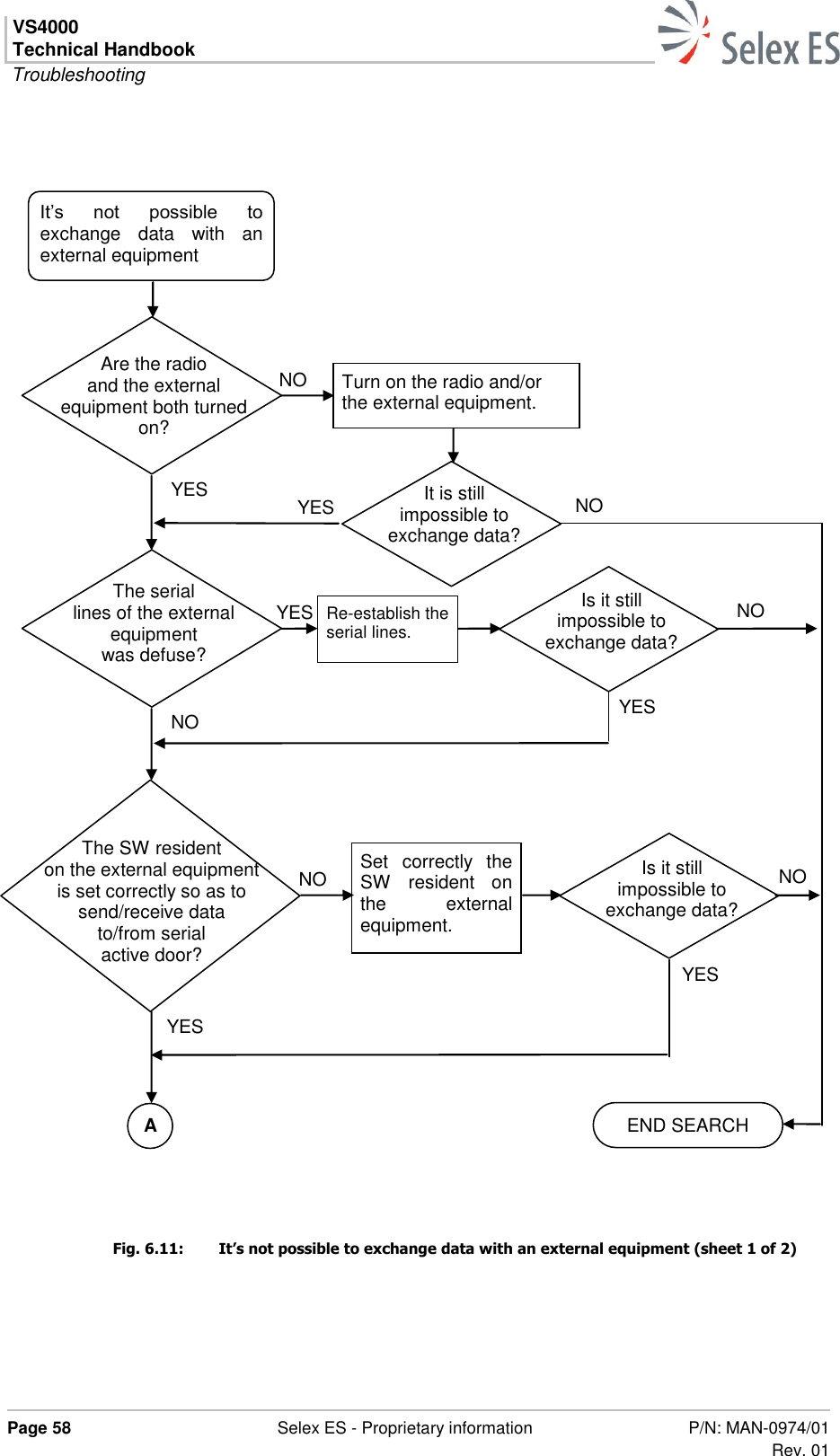
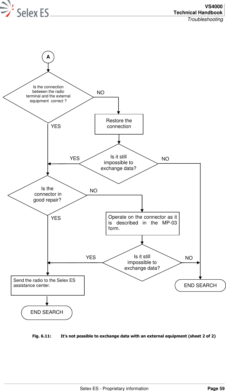
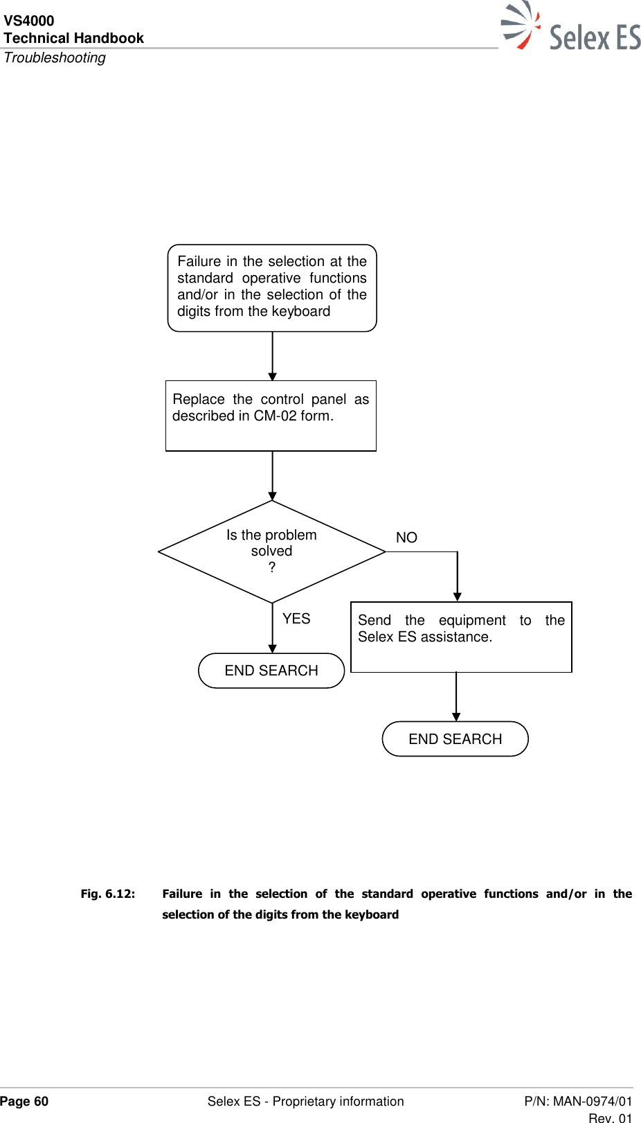
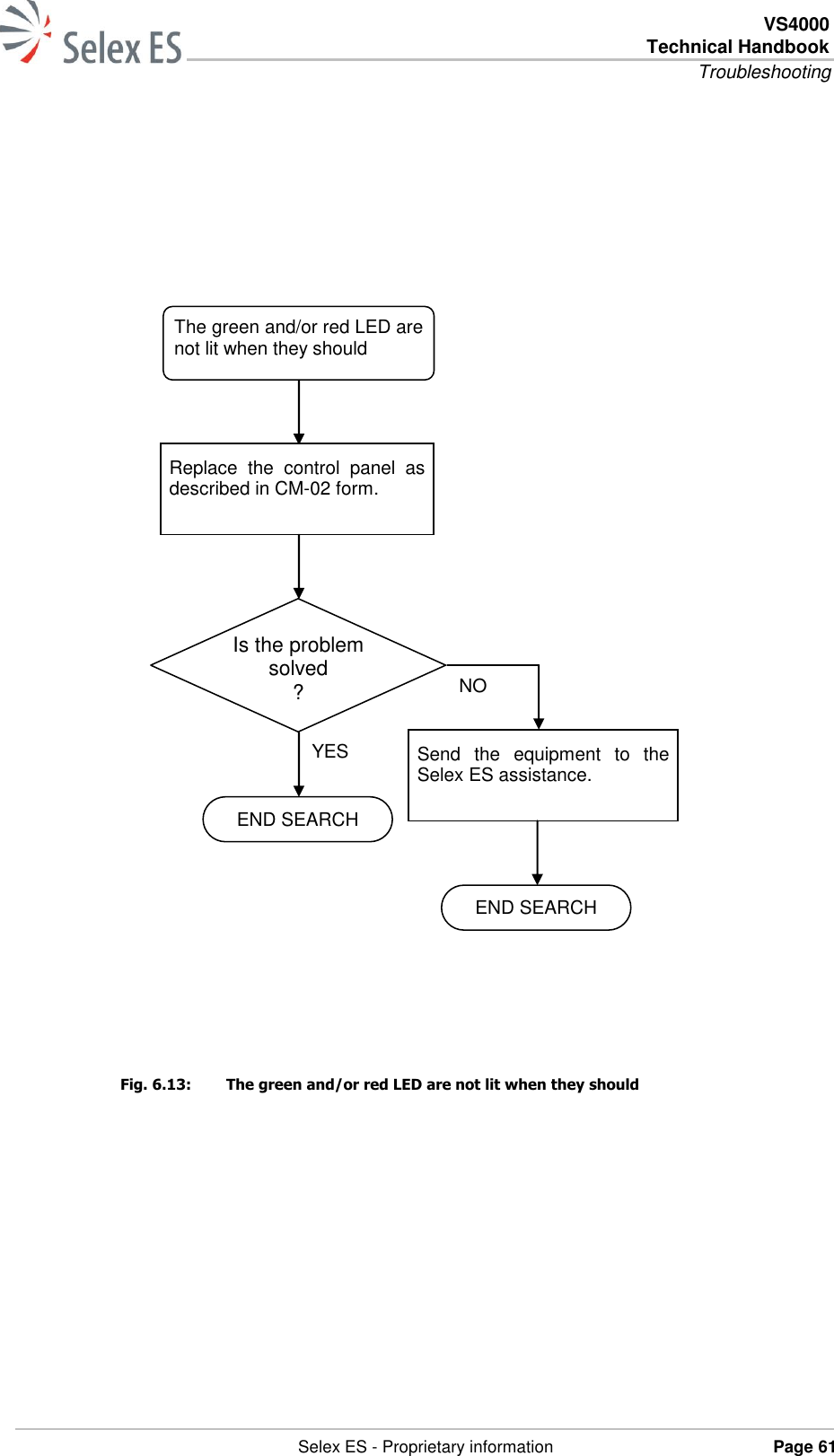
Selex ES VS4000-806-870 VS4000 806-870 User Manual

Selex ES SPA VS4000 806-870 Users Manual

Users Manual

               VS4000 UHF Vehicle Radio Equipment    Technical Handbook   P/N: MAN-0974/01 Rev. 01
VS4000 Technical Handbook    Page ii  Selex ES - Proprietary information P/N: MAN-0974/01 Rev. 01           The information in this document is subject to change without notice and describes only the product defined in the introduction of this documentation. This document is intended for the use of Selex ES  customers only for the purposes of the agreement under which the document is submitted, and no part of it may be reproduced or transmitted in any form or means without the prior written permission of Selex ES . The document has been prepared to be used by professional and properly trained personnel, and the customer assumes full responsibility when using it. Selex ES  welcomes customer comments as part of the process of continuous development and improvement of the documentation.  The information or statements given in this document concerning the suitability, capacity, or performance of the mentioned hardware or software products cannot be considered binding but shall be defined in the agreement made between Selex ES  and the customer. However, Selex ES  has made all reasonable efforts to ensure that the instructions contained in the document are adequate and free of material errors and omissions. Selex ES  will, if necessary, explain issues which may not be covered by the document. Selex ES  liability for any errors in the document is limited to the documentary correction of errors. Selex ES  WILL NOT BE RESPONSIBLE IN ANY EVENT FOR ERRORS IN THIS DOCUMENT OR FOR ANY DAMAGES, INCIDENTAL OR CONSEQUENTIAL (INCLUDING MONETARY LOSSES), that might arise from the use of this document or the information in it. This document and the product it describes are considered protected by copyright according to the applicable laws. Other product names mentioned in this document may be trademarks of their respective companies, and they are mentioned for identification purposes only.   Copyright © Selex ES  S.p.A. 2013. All rights reserved       Selex ES S.p.A. A Finmeccanica Company
 VS4000 Technical Handbook Safety rules   Selex ES - Proprietary information Page iii  Safety rules  Before using the equipment, read all the instructions contained in the manual and with special care those relative to safety.   Lue  käyttöohjeet  ja  erityisesti  turvallisuuteen  liittyvat  ohjeet  ennen laitteen käyttöä.   Alvorens  over  te  gaan  tot  het  gebruik  van  het  apparaat  lees    met aandacht al de instructies van het handboek en let vooral op die die de veiligheid betreffen.   Alvorens het apparaat in gebruik te nemen lees alle instructies van het handboek en  vooral de voorschriften betreffende  de veiligheid.   Avant  toute  utilisation  de  l’appareil,  lire  toutes  les  indications contenues  dans  le  Manuel  et  avec  une  attention  particulière  celles relatives à la sécurité.   Läs alla instruktioner i denna manual innan ni använder apparaten och då särskilt noggrannt de anvisningar som gäller säkerheten.   Læs  alle  de  vejledninger,  der  er  indeholdt  i  manualen  med  særlig opmærksomhed  på  de  vejledninger,  der  vedrører  sikkerheden,  før apparatet tages i brug.   Vor  Gebrauch  des  Geräts  alle  in  dieser  Bedienungsanleitung enthaltenen Anweisungen und Vorschriften lesen. Den  Sicherheitsbestimmungen  ist  dabei  besondere  Aufmerksamkeit zu widmen.
VS4000 Technical Handbook  Safety rules  Page iv  Selex ES - Proprietary information P/N: MAN-0974/01 Rev. 01   Πριν  χρησιμοποιήσετε  τη  συσκευή  διαβάστε  όλες  τις  οδηγίες  που περιέχονται  στο  εγχειρίδιο  και  δώστε  ιδιαίτερη  προσοχή  στης οδηγίες ασφαλείας.   Prima  di  utilizzare  l’apparecchiatura  leggere  tutte  le  indicazioni contenute nel manuale e con particolare attenzione quelle relative alla sicurezza.   Antes de utilizar el equipo leer todas las instrucciones contenidas en el manual, poniendo particular atención a las de seguridad.   Antes de utilizar o aparelho, leia todas as instruções que constam no manual e com muita atenção as instruções relativas à segurança.
 VS4000 Technical Handbook Safety rules   Selex ES - Proprietary information Page v              This equipment is marked      According  to  the  requirements  specified  in  the  R&TTE  directive  1999/5/EC  and the Commission Decision 6th April 2000, the EC marking is accompanied by the Class II equipment class identifier.  This equipment is intended for sell and use in AT, BE, CY, CZ, DK, EE, FI, FR, DE, GR, HU, IE, IT, LV, LT, LU, MT, NL, PL, PT, SK, SI, ES, SE, GB. This equipment requires authorization or license for use. This equipment operates on frequency bands non-harmonised in the EU. This equipment can also be used worldwide where the equipment is approved for use
VS4000 Technical Handbook  Safety rules  Page vi  Selex ES - Proprietary information P/N: MAN-0974/01 Rev. 01  Selex  ES  S.p.A.  tímto  prohlašuje,  že  tento  VS4000  je  ve  shodě  se  základními požadavky a dalšími příslušnými ustanoveními směrnice 1999/5/ES. Undertegnede Selex ES S.p.A. erklærer herved, at følgende udstyr VS4000 overholder de væsentlige krav og øvrige relevante krav i direktiv 1999/5/EF. Hiermit erklärt Selex ES S.p.A., dass sich das Gerät VS4000 in Übereinstimmung mit den grundlegenden Anforderungen und den übrigeneinschlägigen Bestimmungen der Richtlinie 1999/5/EG befindet. Käesolevaga kinnitab Selex ES S.p.A. seadme VS4000 vastavust direktiivi 1999/5/EÜ põhinõuetele ja nimetatud direktiivist tulenevatele teistele asjakohastele sätetele. Hereby, Selex ES S.p.A., declares that this VS4000 is in compliance with the essential requirements and other relevant provisions of Directive 1999/5/EC. Por  medio  de  la  presente  Selex  ES  S.p.A.  declara  que  el  VS4000  cumple  con  los requisitos esenciales  y cualesquiera otras disposiciones  aplicables o  exigibles de la Directiva 1999/5/CE. ΜΕ  ΤΗΝ  ΠΑΡΟΥΣΑ  Selex  ES  S.p.A.  ΔΗΛΩΝΕΙ  ΟΤΙ  VS4000  ΣΥΜΜΟΡΦΩΝΕΤΑΙ ΠΡΟΣ  ΤΙΣ  ΟΥΣΙΩΔΕΙΣ  ΑΠΑΙΤΗΣΕΙΣ  ΚΑΙ  ΤΙΣ  ΛΟΙΠΕΣ  ΣΧΕΤΙΚΕΣ  ΔΙΑΤΑΞΕΙΣ  ΤΗΣ ΟΔΗΓΙΑΣ 1999/5/ΕΚ. Par  la  présente  Selex  ES  S.p.A.  déclare  que  l'appareil  VS4000  est  conforme  aux exigences  essentielles  et  aux  autres  dispositions  pertinentes  de  la  directive 1999/5/CE. Hér  með  lýsir Selex ES S.p.A. yfir því að VS4000 er í samræmi  við grunnkröfur og aðrar kröfur, sem gerðar eru í tilskipun 1999/5/EC Con la presente Selex ES S.p.A. dichiara che questo VS4000 è conforme ai requisiti essenziali ed alle altre disposizioni pertinenti stabilite dalla direttiva 1999/5/CE. Ar  šo  Selex  ES S.p.A.  deklarē,  ka  VS4000  atbilst  Direktīvas  1999/5/EK  būtiskajām prasībām un citiem ar to saistītajiem noteikumiem. Šiuo  Selex  ES S.p.A.  deklaruoja,  kad  šis  VS4000  atitinka  esminius  reikalavimus  ir kitas 1999/5/EB Direktyvos nuostatas. Hawnhekk,  Selex  ES  S.p.A.,  jiddikjara  li  dan  VS4000  jikkonforma  mal-ħtiġijiet essenzjali u ma provvedimenti oħrajn relevanti li hemm fid-Dirrettiva 1999/5/EC. Alulírott, Selex ES S.p.A. nyilatkozom, hogy a VS4000 megfelel a vonatkozó alapvetõ követelményeknek és az 1999/5/EC irányelv egyéb elõírásainak. Hierbij verklaart Selex ES S.p.A. dat het toestel VS4000 in overeenstemming is met de essentiële eisen en de andere relevante bepalingen van richtlijn 1999/5/EG. Selex  ES  S.p.A.  erklærer  herved  at  utstyret  VS4000  er  i  samsvar  med  de grunnleggende krav og øvrige relevante krav i direktiv 1999/5/EF.
 VS4000 Technical Handbook Safety rules   Selex ES - Proprietary information Page vii  Niniejszym  Selex  ES  S.p.A.  oświadcza,  że  VS4000  jest  zgodny  z  zasadniczymi wymogami oraz pozostałymi stosownymi postanowieniami Dyrektywy 1999/5/EC Selex ES S.p.A. declara que este VS4000 está conforme com os requisitos essenciais e outras disposições da Directiva 1999/5/CE. Selex ES S.p.A. izjavlja, da je ta VS4000 v skladu z bistvenimi zahtevami in ostalimi relevantnimi določili direktive 1999/5/ES. Selex  ES S.p.A.  týmto  vyhlasuje,  že  VS4000  spĺňa  základné  požiadavky  a  všetky príslušné ustanovenia Smernice 1999/5/ES. Selex ES S.p.A. vakuuttaa täten että VS4000 tyyppinen laite on direktiivin 1999/5/EY oleellisten vaatimusten ja sitä koskevien direktiivin muiden ehtojen mukainen. Härmed intygar Selex ES S.p.A. att denna VS4000 står I överensstämmelse med de väsentliga egenskapskrav och övriga relevanta bestämmelser som framgår av direktiv 1999/5/EG.   The  full  declaration  of  conformity  may  be  requested  to  Selex  ES  S.p.A.,  Quality Function, via A. Einstein 35 – 50013 – Campi Bisenzio Firenze ITALY.
VS4000 Technical Handbook  Safety rules  Page viii  Selex ES - Proprietary information P/N: MAN-0974/01 Rev. 01  PAGE INTENTIONALLY LEFT BLANK
 VS4000 Technical Handbook Summary   Selex ES - Proprietary information Page ix  Summary REFERENCE STANDARD ........................................................................ XVII FCC APPROVAL ...................................................................................... XIX 1. GENERAL INFORMATION ..................................................................... 1 1.1 INTRODUCTION ....................................................................................................... 1 1.2 GENERAL CHARACTERISTICS .................................................................................... 3 1.3 TECHNICAL CHARACTERISTICS ................................................................................. 4 1.4 MAINTENANCE ......................................................................................................... 6 1.5 MAIN COMPONENTS ................................................................................................. 7 1.6 SAFETY RECOMMENDATIONS .................................................................................... 9 1.7 ESD PRECAUTIONS ................................................................................................. 12 2. TECHNICAL DESCRIPTION ................................................................. 13 2.1 INTRODUCTION ..................................................................................................... 13 2.2 GENERAL DESCRIPTION .......................................................................................... 13 2.2.1 VS4000 connectors overview ......................................................................... 13 2.3 FPG3 FRONT PANEL ................................................................................................ 16 2.4 RADIO UNIT ........................................................................................................... 17 2.5 FUNCTIONAL DESCRIPTION .................................................................................... 19 2.5.1 Power Supply ................................................................................................ 19 2.5.1.1 ON/OFF Circuit .................................................................................... 20 2.5.2 PLL .............................................................................................................. 21 2.5.3 Receiver ....................................................................................................... 22 2.5.4 Transmitter .................................................................................................. 23 2.5.5 Base Band Section ........................................................................................ 25 2.5.5.1 Microphone Lines management ............................................................ 27 2.5.5.2 PTT line management .......................................................................... 29 2.5.5.3 AF Output Power ................................................................................. 30 3. SETTING UP ........................................................................................ 31 3.1 INTRODUCTION ..................................................................................................... 31 3.2 SETTINGS .............................................................................................................. 32 3.2.1 HW/SW Configurations .................................................................................. 32 3.2.2 Connecting the equipment and the computer .................................................. 32 3.3 GENERAL DESCRIPTION .......................................................................................... 33 3.4 PRP PROGRAMMING PACKAGE SERVICE GUIDE ........................................................ 34 4. DISPOSAL ........................................................................................... 35
VS4000 Technical Handbook  Summary  Page x  Selex ES - Proprietary information P/N: MAN-0974/01 Rev. 01  4.1 INTRODUCTION ...................................................................................................... 35 4.2 DISMANTLING AND DISPOSAL ................................................................................. 36 4.3 PROVISIONS FOR RE-USE ....................................................................................... 37 5. PREVENTIVE MAINTENANCE .............................................................. 39 5.1 INTRODUCTION ...................................................................................................... 39 5.2 COLLECTION OF PREVENTIVE MAINTENANCE FORMS .............................................. 40 6. TROUBLESHOOTING ........................................................................... 47 6.1 INTRODUCTION ...................................................................................................... 47 6.2 RADIO TESTS WITH THE RADIO TEST SET .............................................................. 48 6.2.1 Tests with Radio Test Set .............................................................................. 48 6.3 TROUBLESHOOTING FLOW DIAGRAMS .................................................................... 55 6.3.1 VS4000: troubleshooting flow diagrams .......................................................... 55 6.4 FUNCTIONAL TEST ................................................................................................. 65 7. CORRECTIVE MAINTENANCE ............................................................. 75 7.1 INTRODUCTION ...................................................................................................... 75 7.2 COLLECTION OF CORRECTIVE MAINTENANCE FORMS .............................................. 75 APPENDIX A: ACCESSORIES .............................................................. 83 A.1 SUBJECTS TREATED ................................................................................................ 83 A.2 MICROPHONE ......................................................................................................... 83 A.3 LOUDSPEAKER ........................................................................................................ 85 A.4 VS4000 ANTENNA ................................................................................................... 86 A.5 MAGNETIC HOOK HANDSET .................................................................................... 87 A.6 GPS ANTENNA ........................................................................................................ 89 A.7 DOWNLOADING KEY ASSEMBLE .............................................................................. 90 A.8 HANDSFREE KIT ..................................................................................................... 90  WORDBOOK   ....................................................................................... I
 VS4000 Technical Handbook List of figures   Selex ES - Proprietary information Page xi  List of figures Fig. 1.1: VS4000 equipment overview ...................................................................................... 3 Fig. 2.1: IFP Interface .......................................................................................................... 14 Fig. 2.2: Remoted Front Panel installation .............................................................................. 15 Fig. 2.3: Equipment structure ................................................................................................ 17 Fig. 2.4: Block diagram ......................................................................................................... 18 Fig. 2.5: Power supply scheme .............................................................................................. 19 Fig. 2.6: ON/OFF Circuit ....................................................................................................... 20 Fig. 2.7: PLL Architecture ...................................................................................................... 21 Fig. 2.8: Receiver block scheme ............................................................................................ 22 Fig. 2.9: Transmitter block scheme ........................................................................................ 24 Fig. 2.10: Base Band section block scheme .............................................................................. 26 Fig. 2.11: Microphone lines management ................................................................................ 28 Fig. 2.12: PTT line.................................................................................................................. 29 Fig. 6.1: Tetra Radio Test Set ............................................................................................... 48 Fig. 6.2: SYSTEMS key ......................................................................................................... 49 Fig. 6.3: System selection ..................................................................................................... 49 Fig. 6.4: Channel selection .................................................................................................... 50 Fig. 6.5: DATA keys .............................................................................................................. 50 Fig. 6.6: Red “ENTER” keys .................................................................................................. 51 Fig. 6.7: “Manual Test” and “Mode” ....................................................................................... 52 Fig. 6.8: Adjustment knob .................................................................................................... 54 Fig. 6.9: It‘s not possible to control the volume of the loudspeaker ......................................... 56 Fig. 6.10: The equipment doesn’t turn on ................................................................................ 57 Fig. 6.11: It’s not possible to exchange data with an external equipment (sheet 1 of 2) ............. 58 Fig. 6.11: It’s not possible to exchange data with an external equipment (sheet 2 of 2) ............. 59 Fig. 6.12: Failure in the selection of the standard operative functions and/or in the selection of the digits from the keyboard ....................................................................................... 60 Fig. 6.13: The green and/or red LED are not lit when they should ............................................. 61 Fig. 6.14: The FPG3 display is out of order or it shows wrong symbols ...................................... 62 Fig. 6.15: The  radio  link,  within  the  normal  coverage  area,  is  impossible,  intermittent  or  faint (sheet 1 of 2) ...................................................................................................... 63 Fig. 6.15: The  radio  link,  within  the  normal  coverage  area,  is  impossible,  intermittent  or  faint (sheet 2 of 2) ...................................................................................................... 64 Fig. 6.16: Registration test ..................................................................................................... 66 Fig. 6.17: Call test .................................................................................................................. 67 Fig. 6.18: RX test ................................................................................................................... 68 Fig. 6.19: Test on quality of the received LF ............................................................................ 69 Fig. 6.20: TX test (sheet 1 of 2) .............................................................................................. 70 Fig. 6.20: TX test (sheet 2 of 2) .............................................................................................. 71 Fig. 6.21: Test on quality of the transmitted LF (sheet 1 of 2) ................................................... 72 Fig. 6.21: Test on quality of the transmitted LF (sheet 2 of 2) ................................................... 73
VS4000 Technical Handbook  List of figures  Page xii  Selex ES - Proprietary information P/N: MAN-0974/01 Rev. 01  Fig. A.1: Microphone MK1B ................................................................................................... 83 Fig. A.2: Microphone connector ............................................................................................. 84 Fig. A.3: Loudspeaker ........................................................................................................... 85 Fig. A.4: Antennas ................................................................................................................ 86 Fig. A.5: Handset ................................................................................................................. 87 Fig. A.6: Hanger to install the GPS magnetic antenna ............................................................. 89 Fig. A.7: Downloading Key Assembly ..................................................................................... 90 Fig. A.8: Handsfree kit connection scheme ............................................................................. 90
 VS4000 Technical Handbook List of tables   Selex ES - Proprietary information Page xiii  List of tables Tab. 1.1: Technical characteristics ............................................................................................ 4 Tab. 1.2: Maintenance levels .................................................................................................... 6 Tab. 1.3: VS4000 main components ......................................................................................... 7 Tab. 5.1: Summary of the preventive maintenance operations ................................................. 40 Tab. 6.1: Parameters ............................................................................................................. 53 Tab. 6.2: Radio terminal VS4000 troubleshooting .................................................................... 55 Tab. 6.3: Description of the symbols used in the troubleshooting flow diagrams ........................ 56 Tab. 7.1: Summary of the corrective maintenance operations .................................................. 75 Tab. A.1: Microphone characteristics ....................................................................................... 83 Tab. A.2: Microphone connector pin out .................................................................................. 84 Tab. A.3: Loudspeaker characteristics ..................................................................................... 85 Tab. A.4: Handset characteristics ........................................................................................... 88 Tab. A.5: GPS antenna characteristics ..................................................................................... 89
VS4000 Technical Handbook  List of tables  Page xiv  Selex ES - Proprietary information P/N: MAN-0974/01 Rev. 01  PAGE INTENTIONALLY LEFT BLANK
 VS4000 Technical Handbook Issue record sheet   Selex ES - Proprietary information Page xv  Issue record sheet Title:  VS4000 UHF Vehicle Radio Equipment - Technical Handbook Document code MAN-0974/01 Date Main variations applied Rev. June 2015 First Issue 01
VS4000 Technical Handbook  Issue record sheet  Page xvi  Selex ES - Proprietary information P/N: MAN-0974/01 Rev. 01  PAGE INTENTIONALLY LEFT BLANK
 VS4000 Technical Handbook Issue record sheet   Selex ES - Proprietary information Page xvii  REFERENCE STANDARD  EN 303 035-1 “Terrestrial Trunked Radio (TETRA) Harmonized EN for TETRA equipment covering essential requirements under article 3.2 of the R&TTE Directive; Part 1: Voice plus Data (V+D)”  EN 303 035-2 “Terrestrial Trunked Radio (TETRA) Harmonized EN for TETRA equipment covering essential requirements under article 3.2 of the R&TTE Directive; Part 2: Direct Mode Operation (DMO)”  ETSI EN 301 489-1 Electromagnetic compatibility and Radio spectrum Matters (ERM); ElectroMagnetic Compatibility (EMC) standard for radio equipment and services; Part 1: Common technical requirements  ETSI EN 301 489-18  Electromagnetic Compatibility (ECM) standards for radio equipment and services – Part 18: Specific conditions for TETRA equipment  CENELEC EN 60950-1 Information Technology Equipment – Safety  Directive 72/245/EEC (EMC Automotive) on the approximation of the laws of the Member States relating to the suppression of radio interference produced by spark-ignition engines fitted to motor vehicles  ETSI EN 300 394-1 TETRA Conformal Testing Specification – Part 1: Radio  ETSI EN 302 561 Electromagnetic compatibility and Radio spectrum Matters (ERM); Land Mobile Service; Radio equipment using constant or non-constant envelope modulation operating in a channel bandwidth of 25 kHz, 50 kHz, 100 kHz or 150 kHz; Harmonized EN covering essential requirements of article 3.2 of the R&TTE Directive  ETSI EN 300 392-2 Terrestrial Trunked Radio (TETRA);Voice plus Data (V+D);Part 2: Air Interface (AI)  ETSI EN 300 396-2 Terrestrial  Trunked  Radio  (TETRA)  - Technical  Requirements  for  Direct  Mode Operation (DMO) - Part 2: Radio Aspects  ETSI EN 300 396-4 Terrestrial  Trunked  Radio  (TETRA)  -
VS4000 Technical Handbook  Issue record sheet  Page xviii  Selex ES - Proprietary information P/N: MAN-0974/01 Rev. 01  Technical  Requirements  for  Direct  Mode Operation (DMO) - Part 4: Type 1 repeater air interface  ETSI EN 300 396-5 Terrestrial  Trunked  Radio  (TETRA)  - Technical  Requirements  for  Direct  Mode Operation  (DMO)  -  Part  5:  Gateway  air interface
 VS4000 Technical Handbook Issue record sheet   Selex ES - Proprietary information Page xix  FCC APPROVAL FCC approval  VS4000  806-870  vehicular equipment  complies  with  Part  15  of  the  FCC/Federal Communication Commission regulations. Operation is governed by the following: FCC ID:     X5YVS4000-806-870 These devices comply with part 15 of the FCC Rules. Operation is subject to the following two conditions: -  these devices may not cause harmful interference, and -  these devices must accept any interference received, including interference that may cause undesired operation.  Any  unauthorized  modifications  or  changes  to  these  devices  could  void  the  user’s authority to operate these devices.     Note: FCC ID X5YVS4000-806-870 apply to VS4000 806-870 model.
VS4000 Technical Handbook  Issue record sheet  Page xx  Selex ES - Proprietary information P/N: MAN-0974/01 Rev. 01  RF Exposure Compliance   The described product is intended for use in occupational/controlled conditions, where users have full knowledge of their exposure and can exercise control over their exposure to meet R&TTE and FCC/IC limits. This apparatus is NOT authorized for any other use.  Using an omnidirectional antenna with gain of 6,13 dB, the following values of Power density were measured:   Position Maximum measured Power Density  (mW/cm2) FCC limit  (mW/cm2) Internal positions (driver and passengers seats) 0,006 0,549 External by stander (at a minimum distance of 72 cm from antenna) 0,004 0,579
 VS4000 Technical Handbook General Information   Selex ES - Proprietary information Page 1  1. GENERAL INFORMATION 1.1 INTRODUCTION This technical manual contains the description of the VS4000 vehicular radio, a mobile form of radio communication equipment operating in 806÷870 MHz band.   The  VS4000  transceiver  is  a  frequency  synthetized  equipment  controlled  by  a microprocessor and designed for voice and data reception/transmission according to TETRA communication system.  The  information  and  descriptions  given  in  this  manual  are  related  to  product development. Therefore they may change according to the product release. The manual is divided into the following sections: Section 1: General information The  equipment’s  purpose,  structure,  functions,  main  technical  data  and  safety recommendations are described in this section. Section 2: Technical description The functional description of each assembly present in the equipment is contained in this section. Section 3: Setting Up The procedures for inspection and setting up of the equipment are described in this section. Section 4: Disposal Information on the disposal of equipment parts is given in this section. Section 5: Preventive maintenance The  preventive  maintenance  procedures  of  the  equipment  are  described  in  this section. Section 6: Troubleshooting Information  on  troubleshooting  procedures  of  the  equipment  are  described  in  this section.
VS4000 Technical Handbook  General Information  Page 2  Selex ES - Proprietary information P/N: MAN-0974/01 Rev. 01  Section 7: Corrective maintenance Information on corrective maintenance procedures of the equipment are described in this section. Appendix A:  Accessories Contains information on accessories of the equipment.  For the VS4000 use see the relative User Guide, for the VS4000 installation see the relative Installation Guide.
 VS4000 Technical Handbook General Information   Selex ES - Proprietary information Page 3  1.2 GENERAL CHARACTERISTICS The  VS4000  equipment  is  a  digital  vehicular  radio  terminal  designed  in  compliance with the TETRA standard. The equipment comprises two main modules: the Radio Unit transceiver and the Front Panel. The Radio Unit consists of a single piece, die-cast aluminium container that contains the boards with the circuitry for signal processing both in transmission and reception phase. The Front Panel acts as an interface between the operator and the transceiver. The  VS4000  equipment  is  shown  in  Fig.  1.1.  The  Front  Panel  is  installed  on  the dashboard. The transceiver is installed in the boot (trunk) of the vehicle, up to 6 metres from the Front Panel.   Fig. 1.1:  VS4000 equipment overview  1 VS4000 radio unit   2 Loudspeaker 3 Microphone 4 FPG3 universal front panel  2 3 4 1
VS4000 Technical Handbook  General Information  Page 4  Selex ES - Proprietary information P/N: MAN-0974/01 Rev. 01  1.3  TECHNICAL CHARACTERISTICS The VS4000 equipment main technical characteristics in Tab. 1.1 are shown. Tab. 1.1:  Technical characteristics Parameters Type/Value VS4000 Radio body Mechanical characteristics Dimensions 47.3x134x178 mm (DIN compliant) Weight 1.15 Kg Protection to dust and water IP54 Shock and vibrations MIL STD-810 F ETSI EN 300 019-2-1 ETSI EN 300 019-2-2 Electrical characteristics RF Power 10 W (Class 2 Tetra)1 3 W   (Class 3 Tetra)1 Frequency Band 806-870 MHz AF Power 8 W (with 4 Ohm load) DC Power Supply 13.2 V (10.8 V÷15.6 V in extreme conditions) Modulation /4 DQPSK (Tetra Standard) Carrier Spacing 25 KHz Frequency offset Tetra Standard with 0, 6.25, 12.5 kHz RF Performance Compliance ETSI EN 300 392-2  Operative Temperature  -25°C / +55°C Storage Temperature -40°C / +85°C Functional characteristics Standard TETRA Tetra mods TMO DMO + Idle Dual Watch DMO Repeter 1A / 1B DMO Gateway Internal options E2E Encryption module GPS RX module                                                            1 The multislot TX for TETRA, foresee a time/temperature limit.
 VS4000 Technical Handbook General Information   Selex ES - Proprietary information Page 5   Parameters Type/Value Special boards (to be developed)  External options SIM card External interfaces RS232 serial PEI   TNC main antenna   GPS Antenna   Remoted Front Panel Connector   Power Supply Connector   Auxiliary Connector Reference STANDARD TETRA standard Reference ETSI EN 300 392-2 ETSI EN 300 396-2 ETSI EN 300 396-4 ETSI EN 300 396-5 Parameters Type/Value FPG3 Front Panel (vehicular) Operative temperature range -20°C ÷ +60°C Storage temperature range -40°C ÷ +85°C Voltage range +9 ÷ +15.6 V Nominal voltage +13.2 V Polarity Negative To GND Over voltage protection By transorb Voltage fall protection By reset Polarity inversion protection By diode Current absorption < 180 mA Connectors 12 pins; USB-A (only for vehicular); 26 pins female (J1); 26 pins male (P1) Protection from dust and water IP54 Dimensions (without connectors and knob)  T.B.D. Weight < 460 g
VS4000 Technical Handbook  General Information  Page 6  Selex ES - Proprietary information P/N: MAN-0974/01 Rev. 01  1.4 MAINTENANCE Maintenance  concerns  all  the  actions  aimed  to  maintain  or  restore  the  equipment operativity. Maintenance can be preventive (scheduled maintenance) and corrective (unscheduled maintenance). In order to schedule maintenance interventions it is necessary to divide maintenance into levels according to the operations to be carried out. The maintenance levels define the actions and the personnel allowed to carry out the maintenance operations. Three maintenance levels are thus defined:  I:  Equipment Maintenance Level.  II:  Module Maintenance Level.  III: Component Maintenance Level. For example in a TETRA system we can define:   Equipment:  any radio terminal (Hand-held, vehicular or fixed).   Module:  a Base Band of TTU400 of the Base Station BS400.   Component:  any part of a module (e.g. an IC). A description of the maintenance levels is shown in Tab. 1.2. Tab. 1.2:  Maintenance levels Maintenance level Action Personnel I Replacement of an equipment Operator II Replacement of a module of an equipment Maintenance technician III Replacement of a component of a module or equipment Selex ES technician
 VS4000 Technical Handbook General Information   Selex ES - Proprietary information Page 7  1.5 MAIN COMPONENTS The VS4000 main components are listed in Tab. 1.3. Tab. 1.3:  VS4000 main components Description P/N Main elemets Radio unit MODEL VS4000 806-870 VS4000 806-870MHz WITH E2E ENCRYPTION AND GPS TEA1 STD.VERS.   774-1052/01 VS4000 806-870MHz WITH E2E ENCRYPTION AND GPS TEA2 STD.VERS.   774-1053/01 VS4000 806-870MHz WITH E2E  ENCRYPTION AND GPS TEA3 ST.VERS.   774-1054/01 VS4000 806-870MHz WITH ONLY GPS  BOARD TEA2   774-1055/01 VS4000 806-870MHz WITH ONLY GPS  BOARD TEA1   774-1056/01 VS4000 806-870MHz WITH ONLY GPS BOARD TEA3 774-1057/01 VS4000 806-870MHz WITH ONLY GPS BOARD NO TEA 774-1067/01.01       Control Panel (FPG3) 972-0562/03.01 (vehicular) 972-0562/04.01 (vehicular-arabian keyboard) 972-0562/05.01 (vehicular-cyrillic keyboard) Installation Installation kit for FPG3 (vehicular and motorcycle) 971-0536/01 Bracket installation kit VS4000 771-2359/01 Bracket quick lock/release VS4000 970-4929/01
VS4000 Technical Handbook  General Information  Page 8  Selex ES - Proprietary information P/N: MAN-0974/01 Rev. 01  Cable FPG3-VS4000 976-1539/01.01 Cable mains kit VS4000 771-2229/01 Loudspeaker cable VS4000 976-1542/01.01      Description P/N Accessories Antenna  (806÷870): 68720-42/023 Loudspeaker 774-0139/02 Loudspeaker extension cable (6 mt.) LF 976-0099/02 Loudspeaker cable (2,5 mt.) LF 976-1431/01 Microphone HPI-0103/01 Magnetic Hook Handset HPI-0244/01 Hands free kit 771-2058/01 Key downloading Kit 771-2390/01 FPG3 Programming cable HPI-0158/01 Main elemets FPG3 Data cable HPI-0157/01 GPS magnetic antenna  2100045MO295 Hanger to install the GPS antenna (if a metal surface is not available) 970-3614/01 Documentation Technical manual MAN-0974/01
 VS4000 Technical Handbook General Information   Selex ES - Proprietary information Page 9  1.6 SAFETY RECOMMENDATIONS Carefully read all of the cautions and warnings before using the vehicular radio:   Do  not  use  the  radio  equipment  for  uses  different  than  those indicated in the manual.   For a correct  use  of  the radio equipment, read  what  is listed in  the user's guide.   Protect the radio  from  sprinklings of water  and/or other  liquids and from dust.   Be  careful  not  to  damage  the  vehicular  radio  when  cleaning  the vehicle.   Do not place the audio accessories above the airbags or in their area of action.  If the airbag is activated, it may not swell correctly and/or hurl  the  audio  accessory,  with  great  force,  inside  the  passenger compartment where the vehicle occupants are located.   Do not use the vehicular radio if the antenna and/or the antenna cable are damaged.   The electronic  devices are  sensitive to  electromagnetic  interference (EMI)  if  not  adequately  shielded,  designed  or  configured  differently for electromagnetic fields immunity. If electromedical equipment (ex. pace-makers, acoustical equipment, etc.)  is  used  together  with  the  vehicular  radio,  make  sure that  it  is adequately shielded from external electromagnetic fields.   Do  not  take  the  radio  into  environments  that  have  a  potentially explosive atmosphere (ex. fuel storage sites, filling stations, etc.).
VS4000 Technical Handbook  General Information  Page 10  Selex ES - Proprietary information P/N: MAN-0974/01 Rev. 01   Install  the  vehicular  radio  following  the  instructions  given  in  the installation  guide.  The  mounting  screws  can  damage  cables  and wires  that  run  under  some  mounting  surfaces  in  the  vehicle.  Be careful  to  avoid  mounting  the  bracket  above  these  locations.  The equipment must be installed in such a way that it complies with the national regulations in effect.   Carry  out  the  maintenance  interventions  on  the  vehicular  radio following the instructions given in this technical handbooks.   Follow  all  accident  prevention  standards  when  carrying  out maintenance  interventions  on  the  vehicular  equipment  and  use  the proper tools (spanners, screwdrivers,…..).   First  and second  maintenance  level  interventions  on  the  equipment are to be carried out by authorized technicians only.  Third maintenance level interventions are to be carried out by Selex technicians only. The maintenance levels are defined in this technical manual.   Use  only  original  accessories  and  spare  parts,  or  approved  by  the manufacturer,  suitable  for  the  vehicular  radio.    The  use  of  different accessories  and/or  spare  parts  (earphone,  antenna,  etc.)  makes  the safety and electromagnetic compatibility certifications to be valid no more  and  it  could  lower  the  user  safety  level  and/or  generate electromagnetic fields that exceed the accepted limits.  WARNING After  the radio has  been  trasmitting  for  a  long  period,  it  may reach high temperatures: in such a case avoid touching the radio shell.   The emergency call is a priority type call. The  vehicular  radio,  like  all  mobile  telephony  equipment,  operates with  radio  frequency  signals,  therefore,  the  forwarding  of  the  call depends on the network coverage at the moment of the call.
 VS4000 Technical Handbook General Information   Selex ES - Proprietary information Page 11    If  you  need  send  an  emergency  call,  keep  pressed  the  emergency button for at least 2 seconds, when the radio is switched on. Relating on  the  radio  setting  (from  PRP),  two  cases  may  occur  if  the trasmission is inhibit:  a) the emergency call is not sent; it is necessary to disable the Tx Inhibit founction from radio menu to foward a call (even if the call is an emergency call). b)  the  emergency  call  is  sent  and  automatically  the  Tx  Inhibit function is disabled; from radio menu it is possible to recover the Tx Inhibit function again    The  radio  complies  with  all  product  specifications  and  great  care  is  taken  by  the manufacturer so that user safety, as far as the effects of electromagnetic waves on health are concerned, is guaranteed within the limits established by the international specifications.
VS4000 Technical Handbook  General Information  Page 12  Selex ES - Proprietary information P/N: MAN-0974/01 Rev. 01  1.7 ESD PRECAUTIONS No ESD precautions have to  be  taken by  the  operator. The  VS4000 vehicular radio and its ancillary parts are designed and manufactured in such a way to not be sensible to electrostatic discharges according to what referred in the EN 301 489-18.
 VS4000 Technical Handbook Technical Description   Selex ES - Proprietary information Page 13  2. TECHNICAL DESCRIPTION 2.1 INTRODUCTION This section contains the functional description of the VS4000 vehicular equipment in order  to  give  the  maintenance  technician  a  good  knowledge  of  the  equipment operating principles. 2.2 GENERAL DESCRIPTION The VS4000 equipment is made up of two main modules:   VS4000 Radio Unit;   Front Panel (FPG3). The  Front  Panel  provides  the  user  with  the  controls  interface,  the  audio  accessory connector, and the USB-A socket (only for mass storage devices).. 2.2.1 VS4000 connectors overview In this paragraph the equipment connectors are described. External connectors on the FPG3 Front Panel The 12 pins connector provides the connection of audio accessories. The  USB-A,  (available  only  for  the  FPG3  vehicular)  provides  the  connection  of  the mass storage devices. The 12 pins connector and the USB-A port are located on the front side of the FPG3. The J1 (26 pins female) connector provides the connection of external accessories. The P1 (26 pins male) connector provides the connection of the Radio Unit. The connectors J1 and P1 on the rear side of the FPG3 are located. Radio Unit external connectors There is one interface side: on the rear side of the Radio Unit (IFP). The IFP interface in Fig. 2.1 is reported.
VS4000 Technical Handbook  Technical Description  Page 14  Selex ES - Proprietary information P/N: MAN-0974/01 Rev. 01      Fig. 2.1:  IFP Interface  The installation with the remoted Front Panel in Fig. 2.2 is reported.   GPS Ant. (Opt.) 12Vdc 26pins IFP Connectors USB-A - LAN MicroSD Socket Antenna
 VS4000 Technical Handbook Technical Description   Selex ES - Proprietary information Page 15     Fig. 2.2:  Remoted Front Panel installation
VS4000 Technical Handbook  Technical Description  Page 16  Selex ES - Proprietary information P/N: MAN-0974/01 Rev. 01  2.3 FPG3 FRONT PANEL The Front Panel is composed of two die-cast half-bearings and it includes.   electronic board;   display (LCD 128x81 FSTN Technology);   backlight diffuser for keyboard and rotary knob;   keyboard (silicone rubber keys). In the following picture, the FPG3 is shown.
 VS4000 Technical Handbook Technical Description   Selex ES - Proprietary information Page 17  2.4 RADIO UNIT The Radio Unit module comprises a die-cast structure closed the four screws/washer fasten the container by means of a cover (see Fig. 2.3).     Fig. 2.3:  Equipment structure  The Radio Unit container provides finned surfaces to dissipate heat (heat-sink).  The Radio Unit electronic circuits are distributed on a card. The VS4000 equipment functional block diagram in Fig. 2.4 is reported.
VS4000 Technical Handbook  Technical Description  Page 18  Selex ES - Proprietary information P/N: MAN-0974/01 Rev. 01               Fig. 2.4:  Block diagram
 VS4000 Technical Handbook Technical Description   Selex ES - Proprietary information Page 19  2.5 FUNCTIONAL DESCRIPTION The radio functional block diagram in Fig. 2.4 is reported. 2.5.1 Power Supply The VS4000 radio power supply is 13.2 V with range 10.8÷15.6 V. The power supply block diagram in Fig. 2.5 is shown.      Fig. 2.5:  Power supply scheme  The diode (CR16) protects against the polarity inversions; the input filter is a low pass filter. VBATTINT is the output of the ON/OFF block and directly supplies:   the RF power Amplifier;   the Audio Power Amplifier;   the Front Panel. The DC/DC converter ( ~ 90%) provides 5.5 V; the linear stabilizers provide all the necessary voltage values.
VS4000 Technical Handbook  Technical Description  Page 20  Selex ES - Proprietary information P/N: MAN-0974/01 Rev. 01  2.5.1.1 ON/OFF Circuit The  VS4000  ON/OFF  management  by  means  of  FPG3  or  remote  switch  in  this paragraph is described. The ON/OFF circuit in Fig. 2.6 is reported.    Fig. 2.6:  ON/OFF Circuit
 VS4000 Technical Handbook Technical Description   Selex ES - Proprietary information Page 21  2.5.2 PLL The DMO gateway functionality is supported by VS4000 equipment. The synthesizer ADF4351 has two differential outputs for the RX and TX chains that can be selected according to the operation mode. The PLL architecture in Fig. 2.7 is explained.        Fig. 2.7:  PLL Architecture
VS4000 Technical Handbook  Technical Description  Page 22  Selex ES - Proprietary information P/N: MAN-0974/01 Rev. 01  2.5.3 Receiver The receiver block scheme in Fig. 2.8 is shown.    Fig. 2.8:  Receiver block scheme  The receiving chain is composed of:   RX/TX switch, that allows to insulate the receiving and transmitting chains;   The 36 dB attenuator is inserted by the VATT1 – VATT2 commands; in particular: -  VATT1 = insert 6dB step attenuation at input LNA; -  VATT2 = insert 6dB step attenuation at output LNA. The  attenuator  assures  a  good  linearity  also  in  DMO  Gateway  Repeater operative modalities.   LNA, which is the low noise amplifier.   CMX 994 integrated receiving module, which convert directly to the intermediate frequency  and  produces  the  analogic  base  band  signals  I/QRX  which  are  the inputs, once digitally converted, of the DSP. The internal mixer is driven by OLB, and VGA manages the variable gain stages.
 VS4000 Technical Handbook Technical Description   Selex ES - Proprietary information Page 23  2.5.4 Transmitter The transmitter block scheme in Fig. 2.9 is shown. The transmitting chain is composed of the following components:   CMX 998 module, which converts to radio frequency the input signal, these input signals are the DSP outputs I/QTX  in the BB section.   MGA 62563 module, which amplifies the RF signal of a fixed amount of 20 dB.   RA45H7687M1 module, which is the power amplifier for 806-870 MHz   Directional coupler.   RX/TX  SWITCH  module,  which  is  the  switch  between  receiver  block  and transmitter block.   L.P. Filter, which is a low pass filter before the transmitting antenna. The output power of this transmitter is +40 dBm.
VS4000 Technical Handbook  Technical Description  Page 24  Selex ES - Proprietary information P/N: MAN-0974/01 Rev. 01      Fig. 2.9:  Transmitter block scheme
 VS4000 Technical Handbook Technical Description   Selex ES - Proprietary information Page 25  2.5.5 Base Band Section In Fig. 2.10 the Base Band section block scheme is shown. The µP + DSP +  Flash 4MB RAM, and FPGA (TIME BASE and AIE) are connected one another by means of the Data Bus. The TIME BASE FPGA and AIE FPGA are of programmable type. The front panel is connected by means of a serial line to the µP. By  means  of  the  TIME  BASE  FPGA  two  serial  lines  are  generated  for  TX  and  RX sections.  The serial TX line drives:   CMX998   TXFLT   ADC/DAC TX  The serial RX line drives:   CMX994   RXFLT   VATT1-VATT2   ADC/DAC RX  The  interface  signals  to  the  R/T  section  and PLL ADF4351 are  all  managed by  the TIME BASE FPGA.
VS4000 Technical Handbook  Technical Description  Page 26  Selex ES - Proprietary information P/N: MAN-0974/01 Rev. 01         Fig. 2.10:  Base Band section block scheme
 VS4000 Technical Handbook Technical Description   Selex ES - Proprietary information Page 27   2.5.5.1 Microphone Lines management The audio codec TPS65950 has two indipendent balanced microphone inputs:  MIC-FG, front panel microphone  MIC-EXT, external microphone MIC-FG pins are available on rear 26 pin connector (J5) MIC-EXT pins are available on 64pin expansion connector (P3). in Fig. 2.11 the microphone lines management scheme is shown.
VS4000 Technical Handbook  Technical Description  Page 28  Selex ES - Proprietary information P/N: MAN-0974/01 Rev. 01       Fig. 2.11:  Microphone lines management
 VS4000 Technical Handbook Technical Description   Selex ES - Proprietary information Page 29    2.5.5.2 PTT line management On the rear J5 connector PTT-EXT is available. PTT line is connected as in Fig. 2.12 is shown.   Fig. 2.12:  PTT line
VS4000 Technical Handbook  Technical Description  Page 30  Selex ES - Proprietary information P/N: MAN-0974/01 Rev. 01   2.5.5.3 AF Output Power The VS4000 equipment is provided of an audio power amplifier final stage of class D ( = 90%). Audio performances of the radio are: 8 W @ 4 Ohm
 VS4000 Technical Handbook Setting up   Selex ES - Proprietary information Page 31  3. SETTING UP 3.1 INTRODUCTION This chapter describes the way to configure a TETRA vehicle equipment by using a suitable tool installed in a PC. This tool, the Programming Package, will be referred to as PRP, in the following description. For further details about PRP see the relevant user guide.
VS4000 Technical Handbook  Setting up  Page 32  Selex ES - Proprietary information P/N: MAN-0974/01 Rev. 01  3.2 SETTINGS 3.2.1 HW/SW Configurations The PC where the PRP is installed must have the following minimum configuration:  128 Mb RAM   One or more serial ports   Minimum graphic resolution: 640 x 480 pixels   Operating system: Windows (95, 98, NT, XP, Win7) The PRP installation is carried out from the PC control Panel or, simply, by executing the file “Setup.exe”, and is completely driven by operating system. A de-compression .zip file is not required. 3.2.2 Connecting the equipment and the computer The connection between the radio and the computer is carried out via Ethernet line by means of the relevant programming.
 VS4000 Technical Handbook Setting up   Selex ES - Proprietary information Page 33  3.3 GENERAL DESCRIPTION The PRP is mainly composed of: 1. an application, resident on the PC, able to manage and carry out the complete configuration of a set of radios; 2. a communication protocol to transfer the information from the PC to the radio terminals; 3. a Boot software to be installed on the equipment to enable communication with the PC. The main functions, allowed by the MMI of the PRP, are the following:   downloading of the Boot software into the radio terminal;   downloading of the code of the equipment;   downloading of the firmware of the equipment;   downloading of the equipment data configuration;  Therefore the MMI provides the interface for managing the database and the users.
VS4000 Technical Handbook  Setting up  Page 34  Selex ES - Proprietary information P/N: MAN-0974/01 Rev. 01  3.4 PRP PROGRAMMING PACKAGE SERVICE GUIDE Detailed  information  about  PRP  use  are  available  on  PRP  Programming  Package service guide.
 VS4000 Technical Handbook Disposal   Selex ES - Proprietary information Page 35  4. DISPOSAL 4.1 INTRODUCTION General  instructions  for  the  disposal  of  hazardous  materials  are  contained  in  this chapter.
VS4000 Technical Handbook  Disposal  Page 36  Selex ES - Proprietary information P/N: MAN-0974/01 Rev. 01  4.2 DISMANTLING AND DISPOSAL When the equipment described in this technical manual comes to the end of its life cycle  and  is  removed  from  service,  special  precautions  must  be  taken  during  the dismantling and disposal phases. National legislation and/or local regulations in effect regarding health, safety and the environment must be carefully followed.  The  owner  is  responsible  for  the  dismantling  of  the  equipment  being  compelled  to safely  disconnect  it  from  supplies,  cables  and  services  before  entrusting  it  to  an authorized disposal and placement company. It is furthermore necessary that the disposal company is aware that the equipment is destined for disposal and NOT for re-use. The nature of any hazard or any hazardous material contained in the equipment must be notified to the disposal company. These hazards may include:   Heavy weight of the equipment;   Flammable materials;   Potentially harmful, corrosive or toxic substances and materials.
 VS4000 Technical Handbook Disposal   Selex ES - Proprietary information Page 37  4.3 PROVISIONS FOR RE-USE Whenever the equipment is destined for sale in order to be re-used, the new owner of the equipment must comply with the laws and regulations in effect in the new country of use, and assume the responsibility for the health and safety of the personnel and the environment as well. It  is  essential  for  the  owner  to  supply  the  potential  purchaser  with  a  copy  of  this technical manual, containing the instructions for safe operation and the procedures to identify potential hazards. In any case, the owner must inform the potential purchaser, in writing, of these hazards. Selex ES disclaims all responsibility for the equipment once it is scrapped or re-sold.
VS4000 Technical Handbook  Disposal  Page 38  Selex ES - Proprietary information P/N: MAN-0974/01 Rev. 01  PAGE INTENTIONALLY LEFT BLANK
 VS4000 Technical Handbook Preventive Maintenance   Selex ES - Proprietary information Page 39  5. PREVENTIVE MAINTENANCE In  this  section  the  information  necessary  to  carry  out  the  preventive  maintenance operations on the radio equipment VS4000 is gathered. 5.1 INTRODUCTION The  preventive  maintenance  operations  required  by  the  equipment  taken  into consideration are  substantially limited to a regular control of their efficiency, a visual inspection and cleaning.  The tools and the consumable materials needed to carry out the maintenance activities are listed, when required, together with the procedures to be followed to carry out the operations.  Moreover  operations  periodicity  and  maintenance  levels  are  also described.  All the information is gathered in the proper preventive maintenance (PM) forms.
VS4000 Technical Handbook  Preventive Maintenance  Page 40  Selex ES - Proprietary information P/N: MAN-0974/01 Rev. 01  5.2 COLLECTION OF PREVENTIVE MAINTENANCE FORMS In  this  chapter  all  the  PM  forms  describing  the  relative  preventive  maintenance operations to be carried out on the radio terminal VS4000 are gathered. All the forms are sequentially numbered. The operations to be carried out are summarised in Tab. 5.1. Tab. 5.1:  Summary of the preventive maintenance operations Description Equipment  Periodicity Form N° Visual inspection and cleaning Radio terminal VS4000 1 Month PM-01 Functional test Radio terminal VS4000 1 Month PM-02 Check of car battery system efficiency and assembly tightness Radio terminal VS4000 1 Month PM-03
 VS4000 Technical Handbook Preventive Maintenance   Selex ES - Proprietary information Page 41     Equipment Radio Terminal VS4000 Operation  Visual inspection and cleaning Required tools - Soft cloth - Brush Consumable materials -  Deoxidizing spray Form number PM-01 Page  1/2 Periodicity Maintenance level 1 Month I PROCEDURE   Read all the safety recommendations before proceeding.   Do not use solvents for the cleaning operation.     Visually check the general condition of the equipment.   Make  sure  that  all  the  connectors  are  in  good  repair;  when  required  operate  with  a deoxidizing spray on the connector’s contacts.   Make  sure  that  all  the  external  connection  cables  are  in  good  repair.  When  required replace the cable.   Make sure that the upper cover is correctly closed.  Carefully clean the unit’s external parts. Remove dust with a soft brush and remove stains with a soft, dry or slightly dampened cloth.   Check the condition of the antenna and of its connector.
VS4000 Technical Handbook  Preventive Maintenance  Page 42  Selex ES - Proprietary information P/N: MAN-0974/01 Rev. 01  Form number PM-01 Page  2/2 PAGE INTENTIONALLY LEFT BLANK  Equipment Radio Terminal VS4000
 VS4000 Technical Handbook Preventive Maintenance   Selex ES - Proprietary information Page 43  Equipment Radio Terminal VS4000 Operation  Functional test Required tools - None Consumable materials -  None Form number PM-02 Page  1/2 Periodicity Maintenance level 1 Month I PROCEDURE   Read all the safety recommendations before proceeding.     With  the  equipment  turned  on,  make  sure  that  the  keyboard  and  PTT  push-buttons operate correctly.  Check the equipment’s operation in all possible operating modes.
VS4000 Technical Handbook  Preventive Maintenance  Page 44  Selex ES - Proprietary information P/N: MAN-0974/01 Rev. 01  Form number PM-02 Page  2/2 PAGE INTENTIONALLY LEFT BLANK  Equipment Radio Terminal VS4000
 VS4000 Technical Handbook Preventive Maintenance   Selex ES - Proprietary information Page 45  Equipment Radio Terminal VS4000 Operation Check of car battery system efficiency and assembly tightness  Required tools - None Consumable materials -  Deoxidizing spray Form number PM-03 Page  1/2 Periodicity Maintenance level 1 Month I PROCEDURE   Read all the safety recommendations before proceeding.     Check the correct working of the equipment, when the car engine is off and the radio is transmitting.  Check the condition of the power supply connector’s contacts and, in particular, the state of oxidation. If necessary clean the contacts with a deoxiding spray.   Check the efficiency of the fuses for protection of the unit.  Make sure that all the equipment’s connectors are properly tightened.  Make  sure  that  the  transceiver  bracket’s  fastening nuts are  properly tightned in order  to avoid the transceiver vibrating.   Check the tightness of the nut that locks the antenna cable.
VS4000 Technical Handbook  Preventive Maintenance  Page 46  Selex ES - Proprietary information P/N: MAN-0974/01 Rev. 01    Form number PM-03 Page  2/2 PAGE INTENTIONALLY LEFT BLANK  Equipment Radio Terminal VS4000
 VS4000 Technical Handbook Troubleshooting   Selex ES - Proprietary information Page 47  6. TROUBLESHOOTING The radio terminal  VS4000 troubleshooting techniques are described in this section. These  techniques are meant to find out failures that cause a bad functioning of the equipment. The information given in this manual takes  into consideration the fact that all the III level  maintenance  operations  will  be  done  only  by  the  Selex  ES  assistance technicians. The descriptions of the replacement procedures which can be done by the purchaser are detailed in section 7 of this technical manual. 6.1 INTRODUCTION The troubleshooting procedures are shown in flow diagrams (see par. 6.3.1). The tests to be carried out by the use of the Radio Test Set on the radio terminal VS4000 are described  in  chapter  6.2.  These  tests  are  aimed  to  find  out  whether  or  not  the equipment works correctly, under a radio point of view. If not, it must be sent to the Selex ES assistance centre.
VS4000 Technical Handbook  Troubleshooting  Page 48  Selex ES - Proprietary information P/N: MAN-0974/01 Rev. 01  6.2 RADIO TESTS WITH THE RADIO TEST SET 6.2.1 Tests with Radio Test Set To carry out the Power Test and the Sensitivity Test on the radio terminal, you need a TETRA RADIO TEST SET (IFR) with the power supply cable and a TNC cable, as well as the radio terminal to be tested.  Note Several functions can be active on the TETRA TEST SET, depending on the release.  To carry out the test:   turn off the RADIO;   disconnect the antenna from the RADIO and replace it with the TNC cable;   connect the other end of the TNC cable to the TETRA RADIO TEST SET; turn on the TETRA RADIO TEST SET (see Fig. 6.1).  Note If the radio terminal to be tested is a portable one (Puma T2/T3), connect to the test set on the most sensitive RF connector (1W); to select this connector, press the “RF select” button; the two leds next to the  connection  selected  will  light  up.    By  default,  the  Tetra  Radio  Test  Set  sets  itself  on  the  least sensitive RF connection (150 W), signaling it with the lighting up of the relative leds; this connection should be used in all cases in which the radio to be tested supplies a maximum power greater than 1 Watt.  1  RF connection 150 W 2  Led signaling RF connection, 150 W 3  RF connection 1 W 4  Led signaling RF connection, 1 W 5  “RF select” button 6  Adjustment knob 7  “Enter” keys 8  Display 9  Keys to the left of screen 10  Keys to the right of screen 11  Keys under screen  Fig. 6.1:  Tetra Radio Test Set
 VS4000 Technical Handbook Troubleshooting   Selex ES - Proprietary information Page 49  When the TETRA RADIO TEST SET is turned on, a screen appears on the display with the initials IFR; the test set saves the data relative to the last test carried out in the memory. By default, the TETRA RADIO TEST SET sets itself in analog mode; to select digital mode, press the ”SYSTEMS” key (see Fig. 6.2) to load the TETRA protocol.   Fig. 6.2:  SYSTEMS key Before  carrying  out  the  test, it  is  necessary to  know which channels are  set  on the terminal (setting from PRP).  Even if there is more than one channel set, it is sufficient to consider just one of them for the purposes of the test. When the “TETRA MOBILE” key is pressed from among the keys to the right of the display (see Fig. 6.3) and, subsequently, when the key in correspondence to “SET-UP” is pressed (from among the keys to the left of the display), a screen appears on the display that allows visualizing “SYSTEM PARAMETERS”; press the “CHANNEL PLAN” key to carry out the search for  the  reference frequency of the terminal being tested (see Fig. 6.4).  Fig. 6.3:  System selection
VS4000 Technical Handbook  Troubleshooting  Page 50  Selex ES - Proprietary information P/N: MAN-0974/01 Rev. 01    Fig. 6.4:  Channel selection Once the frequency has been found, confirm it by pressing the key that corresponds to the operating frequency of the terminal from among those located to the right of the display; the test set finds the frequency band and, when the “CONTROL CHANNEL” button  is  pressed,  shows  all  of  the  available  parameters.    Enter  the  value  of  the parameters using the numeric pad (see Fig. 6.5).   Fig. 6.5:  DATA keys For example:   Control Channel:  2496;   Traffic Channel:  2496;   Time slot:  3 (select from 1 to 4);   Mobile Country Code:  420 (that of the terminal);   Mobile Network Code:  00005 (that of the terminal);   Base Color Code:  (Not useful for carrying out the test).
 VS4000 Technical Handbook Troubleshooting   Selex ES - Proprietary information Page 51  Note If the frequency band of the terminal under test does not appear among those available to the test set, proceed by  creating a  personal  “SET  UP” to  insert  it  (see IFR  manual  relative  to the  TETRA  TEST SET).  Press any one of the red “ENTER” keys to confirm data entry (see Fig. 6.6)   Fig. 6.6:  Red “ENTER” keys  Note It is possible to obtain confirmation (ENTER) by pressing any one of the red keys only when you are not required to press a specific key (ENTER) relative to the required measurement unit.  Note It is possible to reduce the frequency search time through the “BASE COLOUR CODE” item only when several groups of cells are found under the same area.  Once the values relative to the first group of essential parameters have been entered (which are highlighted on the display), press the “MORE” key to highlight the second group of parameters, in order to be able to enter the values relative to these also.  min Rx level for access:  -110  dBm  (indicates  the  minimum  signal  level coming from the BS in order that it be considered by the radio terminal);   max Tx level:  30  dBm  (corresponds  to  the  maximum  signal  level transmitted  by  the  terminal:  1  W  for  portable terminals; 10 W for vehicular/fixed terminals);   access parameters:  -39  dBm (this  value  is  given by  a  relation involving two parameters,  C1 and  C2,  to  determine passage from cell to cell);    the other parameters in this second group are not useful for carrying out the test in question.
VS4000 Technical Handbook  Troubleshooting  Page 52  Selex ES - Proprietary information P/N: MAN-0974/01 Rev. 01  Press  the  “MORE”  key  again  to  access  the  parameters  of  the  third  and  last  group; none of these are useful for carrying out the test.  Note If the parameters of the first group are not entered, the test set remains in “wait mode”; if, instead, the parameters  of  the  second  group  are  not  entered,  the  test  set  operates  anomalously;  finally,  the parameters of the third group do not influence the test in any way.  A screen divided into two parts (see  Fig. 6.7) appears on the RADIO TETRA TEST SET display:   MANUAL TEST:  groups all of the settings given previously   MODE : groups all test values    Fig. 6.7:  “Manual Test” and “Mode”
 VS4000 Technical Handbook Troubleshooting   Selex ES - Proprietary information Page 53  Now turn on the terminal to be tested; it begins to search and then registers itself with its identifier (ITSI), which will appear on the display. When “CALL MOBILE” is pressed, the test set sends a call to the terminal under test; when the terminal accepts the call, it is possible to check the “MODE” data on the test set.  Power Profile: ( “Passed” must appear).   Other parameters are (see Tab. 6.1) “Burst Power” (it can be expressed in dBm or  mW),  “Timing  Error”  (indicates  the  number  of  symbols  read  erroneously), “Frequency  Error”  (frequency error)  and  “Vector  Error”  (referred  to  the  vector (symbol)  transmitted;  the  mean  error  (RMS),  the  peak  error  (PEAK  and  the residual error (RESIDUAL) are specified). Even if only one of the parameters does not comply with the ETSI standard (see Tab. 6.1), “Passed” does not appear next to “Power Profile”. Tab. 6.1:  Parameters Phase Action Expected result 1 After the antenna has been disconnected, connect the terminal to the Tetra Test Set as explained in this chapter of the manual. None. 2 Carry out the necessary settings on the Tetra Test Set (selection of the TETRA environment, selection of transmission mode, operating frequency, etc.) to pick up the carrier. If the Tetra Test Set settings are correct, it receives and demodulates the radio terminal carrier.  Depending on the test set options, various screens appear (constellation diagram, vector modulation diagram, etc.). 3 Check the following on the Tetra Test Set:  RF power RF power(1): 10 dBm/±1,5 dBm (up to 470 MHz) 10 dBm/±2 dBm (in the 870 MHz band) Frequency error Vector error, mean value (RMS)  Vector error, peak value Vector error, residual value SYS INFO (correct decoding of system data) Frequency error (2): <0.1 ppm Vector error, mean value (RMS) (3): <10% Vector error, peak value (4): <30% Vector error, residual value: <5% SYS INFO: correctly decoded 4 Drawing up of Test Report. None. Notes:  (1): In compliance with ETSI 300 392-2 article 6.4.1.1, as recommended in ETSI 300 394-1 article 7.1.1.2 (2): The TETRA RF test set will have a precision in frequency greater than 0.1 ppm (BS diagram) or will be tied to a higher external reference precision.  If similar conditions are not complied with, this measurement is not reliable and should only be considered approximate. (3): In compliance with ETSI 300 392-2 article 6.6.1.2.  (4): In compliance with ETSI 300 392-2 article 6.6.1.2.
VS4000 Technical Handbook  Troubleshooting  Page 54  Selex ES - Proprietary information P/N: MAN-0974/01 Rev. 01  In these tests, the TETRA TEST SET simulates the TETRA network. Power Test When the “CALL MOBILE” button is pressed on the test set, a call is forwarded to the terminal being tested. After having pressed the “RF  GEN”  button, vary the field using the adjustment knob (see Fig. 6.8), weakening it and thus forcing the terminal to increase the transmitted power  until  reaching  its  MAX  power  (1  W  for  portable  terminals,  10  W  for vehicular/fixed terminals).  The change in the fluctuating values (in dBm) will be noted in correspondence to “RX GEN LEVEL”. Sensitivity Test The DYNAMIC SENSITIVITY tests are not carried out in the lab; for this reason, we refer here to STATIC SENSITIVITY. When the “CALL MOBILE” button is pressed on the test set, a call is forwarded to the terminal under test. After having pressed the “RF GEN” button, use the adjustment knob (see Fig. 6.8) to bring the signal to -112 dBm, starting from a higher value (for example, -90 dBm). The call, previously forwarded to the terminal, must remain active up to the value of -112 dBm; to guarantee this, the terminal under test will bring itself to the MAX power value transmitted (1 W for portable terminals and 10 W for vehicular/fixed terminals). At  the  end  of  the  test,  the  operator,  besides  having  carried  out  the  POWER  and SENSITIVITY  TESTS,  also  verifies  the  accuracy  of  all  of  the  radio  terminal parameters.  Note The  POWER  and  SENSITIVITY  TESTS  are  closely  correlated;  in  fact,  the  power  is  controlled  by varying the sensitivity and vice versa.  Fig. 6.8:  Adjustment knob
 VS4000 Technical Handbook Troubleshooting   Selex ES - Proprietary information Page 55  6.3 TROUBLESHOOTING FLOW DIAGRAMS The troubleshooting flow diagrams are gathered in this chapter. These diagrams are meant only for maintenance technical personnel. By starting from a bad functioning symptom we arrive to the corrective operation to be carried  out  in  order  to  remove  the  failure;  the  corrective  action  can  be  a  simple maintenance operation (III level excluded) or it can end in sending the equipment to the Selex ES assistance centre.  The troubleshooting flow diagrams relative to the radio terminal VS4000 are gathered in par. 6.3.1. 6.3.1 VS4000: troubleshooting flow diagrams A summary of the VS4000 radio equipment troubleshooting is shown in Tab. 6.2. In particular: N:  stands for the procedure position in the prospectus; Description:  stands for the symptom and thus the beginning of the fault seeking procedure; Fig. Ref.:  stands  for  the  figure  containing  the  flow  chart  relating  to  the appropriate procedure. Tab. 6.2:  Radio terminal VS4000 troubleshooting N. Description Fig. Ref. 1 It‘s not possible to control the volume of the loudspeaker  6.9 2 The equipment doesn’t turn on 6.10 3 It’s not possible to exchange data with an external equipment  6.11 4 Failure in the selection of the standard operative functions and/or in the selection of the digits from the keyboard 6.12 5 The green and/or red LED are not lit when they should 6.13 6 The FPG3 display is out of order or it shows wrong symbols 6.14 7 The radio link, within the normal coverage area, is impossible, intermittent or faint 6.15
VS4000 Technical Handbook  Troubleshooting  Page 56  Selex ES - Proprietary information P/N: MAN-0974/01 Rev. 01  The troubleshooting procedures are shown in the flow diagrams whose symbols are described in Tab. 6.3. Tab. 6.3:  Description of the symbols used in the troubleshooting flow diagrams Symbol Meaning  Stands for the beginning or the end of the flow diagram. The symptom of the possible fault is described inside the symbol.  Stands for the action to be carried out. This action is described inside the symbol itself.  Stands for a decision to be made. The question that must be answered is shown inside the symbol.  Stands for the term of the search.                    Fig. 6.9:  It‘s not possible to control the volume of the loudspeaker It’s not possible to control the volume of the loudspeaker Replace  the  Front  Panel assembly  as  described  in  the CM-02 form. END SEARCH Is the problem solved? NO YES Send the radio equipment to the Selex ES assistance. END SEARCH
 VS4000 Technical Handbook Troubleshooting   Selex ES - Proprietary information Page 57                               Fig. 6.10:  The equipment doesn’t turn on The equipment doesn’t turn on Is the equipment properly connected to the battery plug? Check  that  both the  contacts  of the  battery  are  in  good  repair, operate,  when  required  as described in the PM-01 form. NO YES Is the fuse in good repair ? Send  the  equipment  to  the Selex ES assistance. END SEARCH Is the problem solved ? NO END SEARCH YES Replace the fuse as described  in  CM-01 form. YES Is the problem solved ? NO END SEARCH YES NO Connect  the equipment  to  the battery plug.
VS4000 Technical Handbook  Troubleshooting  Page 58  Selex ES - Proprietary information P/N: MAN-0974/01 Rev. 01   Fig. 6.11:  It’s not possible to exchange data with an external equipment (sheet 1 of 2) It’s  not  possible  to exchange  data  with  an external equipment Are the radio and the external equipment both turned on? Turn on the radio and/or the external equipment. NO It is still impossible to exchange data? YES NO The SW resident on the external equipment is set correctly so as to send/receive data to/from serial active door? YES Is it still impossible to exchange data? NO The serial lines of the external equipment was defuse? NO YES Set  correctly  the SW  resident  on the  external equipment. NO Is it still impossible to exchange data? NO YES YES END SEARCH YES Re-establish the serial lines. A
 VS4000 Technical Handbook Troubleshooting   Selex ES - Proprietary information Page 59    Fig. 6.11:  It’s not possible to exchange data with an external equipment (sheet 2 of 2) Is the connection between the radio terminal and the external equipment  correct ? YES NO Restore the connection YES NO Is it still impossible to exchange data? Is the  connector in good repair? NO YES Operate on the connector as it is  described  in  the  MP-03 form. Send the radio to the Selex ES assistance center. Is it still impossible to exchange data? YES NO END SEARCH END SEARCH A
VS4000 Technical Handbook  Troubleshooting  Page 60  Selex ES - Proprietary information P/N: MAN-0974/01 Rev. 01                     Fig. 6.12:  Failure  in  the  selection  of  the  standard  operative  functions  and/or  in  the selection of the digits from the keyboard Failure in the selection at the standard  operative  functions and/or in the selection of the digits from the keyboard Replace  the  control  panel  as described in CM-02 form. Is the problem solved ? Send  the  equipment  to  the Selex ES assistance. NO YES END SEARCH END SEARCH
 VS4000 Technical Handbook Troubleshooting   Selex ES - Proprietary information Page 61                    Fig. 6.13:  The green and/or red LED are not lit when they should The green and/or red LED are not lit when they should Replace  the  control  panel  as described in CM-02 form. Is the problem solved ? Send  the  equipment  to  the Selex ES assistance. NO YES END SEARCH END SEARCH
VS4000 Technical Handbook  Troubleshooting  Page 62  Selex ES - Proprietary information P/N: MAN-0974/01 Rev. 01                     Fig. 6.14:  The FPG3 display is out of order or it shows wrong symbols  The Front Panel display is out of  order  or  is  shows  wrong symbols Replace  the  control  panel  as described in CM-02 form. Is the problem solved ? Send  the  equipment  to  the Selex ES assistance. NO YES END SEARCH END SEARCH
 VS4000 Technical Handbook Troubleshooting   Selex ES - Proprietary information Page 63      Note In this flowchart the antenna system is considered in good repair.  Fig. 6.15:  The  radio  link,  within  the  normal  coverage  area,  is  impossible,  intermittent  or faint (sheet 1 of 2) The  radio  link,  within  the normal  coverage  area,  is impossible,  intermittent  or faint Is the “F” symbol present on the Front Panel display? NO Is the antenna cable correctly connected to the equipment? YES Are the antenna connectors in good repair? A YES NO NO YES Restore  the  correct connection. The  symbol  “F” (FALL-BACK) indicates the reduced working  mode  of  the radio  base  station serving  the  terminal belonging  cell,  wait until  the  base  station is fully working again. END SEARCH Is the problem  solved ? Operate  on  the connectors  with  the deoxidizing spray. END SEARCH YES NO Send  the  radio  to  the Selex ES assistance. END SEARCH
VS4000 Technical Handbook  Troubleshooting  Page 64  Selex ES - Proprietary information P/N: MAN-0974/01 Rev. 01                            Note In this flowchart the antenna system is considered in good repair.   Fig. 6.15:  The  radio  link,  within  the  normal  coverage  area,  is  impossible,  intermittent  or faint (sheet 2 of 2)  A Check if the terminal is able to exchange  correctly  radio signals  by  performing  the  test described in the par. 6.2 of this manual. Has the radio successfully performed the test? Send  the  radio  to  the  Selex ES assistance. YES NO The  problem  doesn’t depend  on  the  radio but on the network. END SEARCH END SEARCH
 VS4000 Technical Handbook Troubleshooting   Selex ES - Proprietary information Page 65  6.4 FUNCTIONAL TEST A suitable test bench must be prepared in order to carry out the test procedures. The list of required items, except the terminal to be tested, is given below.   Reference  auxiliary  hand-held  equipment  PUMA  TETRA  or  any  other  TETRA terminal.   Reference microphone.   Reference loudspeaker.   Reference TETRA Base Station. This base station must be located in a suitable area  in  order to  guarantee  the  radio  link  with the  above equipment.  It  must  be configured to have in its database an identifier number for a dummy (test) radio that can be configured each time a radio is tested in order to verify its operation.   PC installed with the software to configure the equipment to be tested and with the parameters of the radio base station.   Cable for the equipment downloading.
VS4000 Technical Handbook  Troubleshooting  Page 66  Selex ES - Proprietary information P/N: MAN-0974/01 Rev. 01                                   Fig. 6.16:  Registration test REGISTRATION TEST Replace the Radio equipment with the reference one. The radio equipment on test is faulty. Does the radio register on the reference BS ? GO TO CALL TEST Does the radio register on the reference BS ? The problem is caused by the reference system.  In particular the BS, the radiating system and the connection between the radio and the antenna must be checked. YES NO YES NO
 VS4000 Technical Handbook Troubleshooting   Selex ES - Proprietary information Page 67                                Fig. 6.17:  Call test Dial the sequence to call the reference hand-held terminal. CALL TEST Go to RX TEST Replace the Radio equipment on test with the reference one. The Radio equipment on test is faulty. The  problem  is  caused  by  the reference system.  In particular the hand-held terminal and the BS must be checked. Dial the sequence to call the reference equipment. The call has  been correctly completed? Replace the control panel with the reference one. The control panel is faulty. YES NO YES NO YES NO The call has  been correctly completed? The call has  been correctly completed?
VS4000 Technical Handbook  Troubleshooting  Page 68  Selex ES - Proprietary information P/N: MAN-0974/01 Rev. 01                                    Fig. 6.18:  RX test  Talk from the hand-held terminal towards the radio equipment. RX TEST Set the MAX volume level on the radio under test Does the radio equipment receive the LF transmitted from the reference hand-held terminal? Replace the Radio equipment to be tested with the reference one.  The problem is caused by the reference system.  In particular the loudspeaker connection must be checked. Go to the received LF quality test. The Radio equipment on test is faulty. YES NO YES NO Does the radio equipment receive the LF transmitted from the reference hand-held terminal?
 VS4000 Technical Handbook Troubleshooting   Selex ES - Proprietary information Page 69                                    Fig. 6.19:  Test on quality of the received LF Talk from the hand-held terminal to the Radio equipment. TEST ON QUALITY OF THE RECEIVED LF Does the Radio equipment clearly receive the LF from the hand-held terminal? Replace the Radio equipment on test with the reference one. The problem is caused by the reference system.  In particular the antenna connection and the loudspeaker integrity must be checked. Go to TX TEST The Radio equipment on test is faulty. Does the Radio equipment clearly receive the LF from the hand-held terminal? YES NO YES NO
VS4000 Technical Handbook  Troubleshooting  Page 70  Selex ES - Proprietary information P/N: MAN-0974/01 Rev. 01                                     Fig. 6.20:  TX test (sheet 1 of 2) Talk from the microphone of the Radio equipment on test to the reference hand-held. TX TEST Set the max volume level of the hand-held terminal Does the hand-held receive the LF from the Radio equipment on test? Replace the Radio equipment on test with the reference one. Go to test for the quality of the transmitted LF. The radio equipment on test is faulty. The Radio equipment on test is OK: set it again in the place of the reference one. Replace the front panel with the reference one. Does the hand-held receive the LF from the Radio equipment on test? YES NO YES NO A
 VS4000 Technical Handbook Troubleshooting   Selex ES - Proprietary information Page 71                                     Fig. 6.20:  TX test (sheet 2 of 2) The problem is caused by the reference wiring (in particular the interconnecting cable from front panel and Radio Unit) or the hand-held terminal. The front panel on test is OK. Set it again in place of the reference front panel. Replace the original microphone with the reference one. The original microphone is faulty. Does the hand-held terminal receive the LF from the Radio equipment on test? The original front panel is faulty. Does the handheld receive the LF from the  Radio equipment on test? A NO YES YES NO
VS4000 Technical Handbook  Troubleshooting  Page 72  Selex ES - Proprietary information P/N: MAN-0974/01 Rev. 01                                     Fig. 6.21:  Test on quality of the transmitted LF (sheet 1 of 2) Talk from the microphone of the Radio equipment on test to the reference hand-held terminal. TEST QUALITY OF THE TRANSMITTED LF Does the hand-held terminal clearly receive the LF from the Radio equipment on test? Replace the Radio equipment on test with the reference one. Check the installation. The Radio equipment  on test is faulty. The Radio equipment on test is OK. Set it again in place of the reference Radio Unit. Replace the front panel with the reference one. Does the Radio equipment clearly receive the LF from the  hand-held terminal? YES NO YES NO A
 VS4000 Technical Handbook Troubleshooting   Selex ES - Proprietary information Page 73                                     Fig. 6.21:  Test on quality of the transmitted LF (sheet 2 of 2)   The problem is caused by the reference system.  In particular the BS, the radiating system or the hand-held terminal. The control panel on test is OK. Set it again in place of the reference front panel. Replace the original microphone with the reference one. The original microphone is faulty. Does the Radio equipment clearly receive the LF from the reference hand- held? The original control panel is faulty. clearly receive the LF from the reference hand-held? A NO YES YES NO Does the Radio equipment
VS4000 Technical Handbook  Troubleshooting  Page 74  Selex ES - Proprietary information P/N: MAN-0974/01 Rev. 01  PAGE INTENTIONALLY LEFT BLANK
 VS4000 Technical Handbook Corrective maintenance   Selex ES - Proprietary information Page 75  7. CORRECTIVE MAINTENANCE The  information  necessary  to  carry  out  the  replacement  operations  relatively  to  the corrective maintenance on the VS4000 radio equipment is gathered in this section. 7.1 INTRODUCTION The  corrective  maintenance  operations  required  by  the  equipment  taken  into consideration are substantially limited to the replacement of replaceable parts. The tools and the consumable materials needed to carry out the maintenance activities are listed, when required, together with the procedures to be followed to carry out the operations. All the information is gathered in the proper corrective maintenance (CM) forms. 7.2 COLLECTION OF CORRECTIVE MAINTENANCE FORMS In  this  chapter  all  the  CM  forms  describing  the  relative  corrective  maintenance operations to be carried out on the VS4000 radio terminal are gathered. All the forms are sequentially numbered. The operations which can be carried out at the I and II maintenance level, without the intervention of the Selex ES assistance centre, are summarised in Tab. 7.1. Tab. 7.1:  Summary of the corrective maintenance operations Frontal panel replacement VS4000 CM-01 VS4000 antenna replacement VS4000 CM-02 VS4000 radio module replacement VS4000 CM-03
VS4000 Technical Handbook  Corrective maintenance  Page 76  Selex ES - Proprietary information P/N: MAN-0974/01 Rev. 01  PAGE INTENTIONALLY LEFT BLANK
 VS4000 Technical Handbook Corrective maintenance   Selex ES - Proprietary information Page 77    Equipment VS4000 Radio System (vehicle configuration) Operation  Front panel replacement Required tools - Screw-driver Consumable materials -  Front panel Form number CM-01 Page  1/2 Periodicity Maintenance level Not applicable I PROCEDURE   Read all the safety recommendations before proceeding.     When the car engine is off, switch OFF the radio system by means the proper button of the front panel.   Disconnect the positive terminal of the power supply cable from the car battery.   Unscrew the four fixing screws (1, Fig. 1) of the control panel and disconnect it from the bracket.
VS4000 Technical Handbook  Corrective maintenance  Page 78  Selex ES - Proprietary information P/N: MAN-0974/01 Rev. 01    Form number CM-01 Page  2/2 Fig. 1  FPG3 removal        1 Bracket (fixed on the dash board) 2 Knobs    Equipment VS4000 Radio System (vehicle configuration)
 VS4000 Technical Handbook Corrective maintenance   Selex ES - Proprietary information Page 79    Equipment VS4000 Radio System Operation  VS4000 antenna replacement Required tools - None Consumable materials - Antenna - De-oxidizing spray Form number CM-02 Page  1/2 Periodicity Maintenance level Not applicable I PROCEDURE   Read all the safety recommendations before proceeding.     Unscrew the antenna (1, Fig. 1) from the TNC connector (2).   Check  the  condition  of  the  connector  and,  when  required,  proceed  as  explained  in  the preventive maintenance PM-01 form.   Screw the new antenna on the TNC connector.  NOTE: the GPS antenna is of magnetic anchoring type.
VS4000 Technical Handbook  Corrective maintenance  Page 80  Selex ES - Proprietary information P/N: MAN-0974/01 Rev. 01    Form number CM-02 Page  2/2  Fig. 1  Antenna replacement    Equipment VS4000 Radio System
 VS4000 Technical Handbook Corrective maintenance   Selex ES - Proprietary information Page 81    Equipment VS4000 Radio System Operation  VS4000 radio module replacement Required tools - Screw-driver Consumable materials -  Radio module Form number CM-03 Page  1/2 Periodicity Maintenance level Not applicable I PROCEDURE   Read all the safety recommendations before proceeding.     When the car engine is off, switch off the radio system by means the proper button of the front panel.   Disconnect the positive terminal of the power supply cable from the vehicle battery.   Disconnect all the cable from the connectors of VS4000 radio module.   Unscrew the fixing screws of the bracket for VS4000 radio module and remove it from the bracket.
VS4000 Technical Handbook  Corrective maintenance  Page 82  Selex ES - Proprietary information P/N: MAN-0974/01 Rev. 01       Form number CM-03 Page  2/2 PAGE INTENTIONALLY LEFT BLANK  Equipment VS4000 Radio System
 VS4000 Technical Handbook Accessories  P/N: MAN-0974/01 Rev. 01 Selex ES - Proprietary information Page 83  APPENDIX A: ACCESSORIES A.1 SUBJECTS TREATED The characteristics of the vehicular equipment’s accessories in this section are given. A.2 MICROPHONE The microphone for the VS4000 with PTT is shown in Fig. A.1; its characteristics are reported in Tab. A.1.   Fig. A.1:  Microphone MK1B  Tab. A.1:  Microphone characteristics Characteristic Type/Value Frequency range 20 to 16000 Hz Sensitivity  -45 dB  4 dB at 1 kHz Impedance < 2.2 K Operating temperature range  -25 to +55 °C
VS4000 Technical Handbook  Accessories  Page 84  Selex ES - Proprietary information P/N: MAN-0974/01 Rev. 01   In next figure the microphone connector with waterproof protection plug, is shown.     Fig. A.2:  Microphone connector  The connector pinout is referred in next table. Tab. A.2:  Microphone connector pin out  Pin Description Pin Description 1 MIC-FG+_CONN 7 ID1_CONN 2 MIC-FG-_CONN 8 RXD-PEI-FG(FRONT)_CONN 3 GND 9 TXD-PEI-FG(FRONT)_CONN 4 PTT-FG_CONN 10 ID2_CONN 5 HOOK_CONN 11 VDC_CONN 6 HEADPHONE_OUT_CONN 12 GND
 VS4000 Technical Handbook Accessories  P/N: MAN-0974/01 Rev. 01 Selex ES - Proprietary information Page 85  A.3 LOUDSPEAKER The loudspeaker, connected to the VS4000 through the Control Panel, is capable of assuring high performance even in very noisy environments, such as a car.      Fig. A.3:  Loudspeaker  Tab. A.3:  Loudspeaker characteristics Parameter Value Audio power 9 W Impedance 4 
VS4000 Technical Handbook  Accessories  Page 86  Selex ES - Proprietary information P/N: MAN-0974/01 Rev. 01  A.4 VS4000 ANTENNA The VS4000 system  has an omnidirectional antenna. For the connection between the antenna and VS4000 radio module is used a coaxial cable. Kind of antenna models are available for the VS4000 Radio System:   omnidirectional TETRA antenna:  In Fig. A.4 the antennas are shown.  Fig. A.4:  Antennas
 VS4000 Technical Handbook Accessories  P/N: MAN-0974/01 Rev. 01 Selex ES - Proprietary information Page 87  A.5 MAGNETIC HOOK HANDSET This accessory is shown in the following figure:     Fig. A.5:  Handset The  magnetic support dimensions are reduced and the efficiency is high. It allows to insert the handset from any direction and with the high magnetic attraction force it is suitable to be used in environmental condition compliant with ETS 300 019-2-5 class IEC 5M3  standard. The water and dust protection is IP54.
VS4000 Technical Handbook  Accessories  Page 88  Selex ES - Proprietary information P/N: MAN-0974/01 Rev. 01  The microphone and earphone caracteristics are reported on the following tables: Tab. A.4:  Handset characteristics Microphone Characteristic Type/Value Type  Electret, water resistance Frequency range 200 to 8000 Hz Power supply 1   10V Current comsumption  300 A max Sensitivity  -62 dB ± 2 dB @ 1 KHz Impedance 3 K  ± 30% @ 1KHz Operating temperature range  -30°C  +60°C Earphone Characteristic Type/Value Frequency range 500 to 3000 Hz Sensitivity  -91 dB S.P.L.  2dB @ 1KHz  Re: 20 Pa Impedance 200 Ohm    40 Ohm Operating temperature range  -30 to +65 °C  The connector used is the same showed in Fig. A.2.
 VS4000 Technical Handbook Accessories  P/N: MAN-0974/01 Rev. 01 Selex ES - Proprietary information Page 89  A.6 GPS ANTENNA This is a compact, active, micropatch GPS antenna and it has a magnetic mounting for quick, convenient placement on any suitable Metal surface. If a metal surface is not available, use the suitable hanger (see Fig A.5) to install the GPS magnetic antenna.   Tab. A.5:  GPS antenna characteristics Parameter Type/Value Dimensions 50,5x42x13,8 mm Weight 115 g (without cable) Power consumption 15 mA (max) Mounting Magnetic Environment -40° to +85° with high humidity    Fig. A.6:  Hanger to install the GPS magnetic antenna
VS4000 Technical Handbook  Accessories  Page 90  Selex ES - Proprietary information P/N: MAN-0974/01 Rev. 01  A.7 DOWNLOADING KEY ASSEMBLE The downloading key assemble is a tool for downloading encryption keys.   Fig. A.7:  Downloading Key Assembly A.8 HANDSFREE KIT The handsfree kit includes:   Cable assembly    Microphone on the wind screen    PTT on the wheel   Fig. A.8:  Handsfree kit connection scheme
  VS4000 Technical Handbook Wordbook  P/N: MAN-0705/01 Rev. 01 Selex ES - Proprietary information Page I    WORDBOOK
VS4000 Technical Handbook  Wordbook  Page II  Selex ES - Proprietary information P/N: MAN-0705/01 Rev. 01  PAGE INTENTIONALLY LEFT BLANK
  VS4000 Technical Handbook Wordbook  P/N: MAN-0705/01 Rev. 01 Selex ES - Proprietary information Page III  Summary  LIST OF ACRONYMS .................................................................................. V
VS4000 Technical Handbook  Wordbook  Page IV  Selex ES - Proprietary information P/N: MAN-0705/01 Rev. 01  PAGE INTENTIONALLY LEFT BLANK
  VS4000 Technical Handbook Wordbook  P/N: MAN-0705/01 Rev. 01 Selex ES - Proprietary information Page V  LIST OF ACRONYMS  4w-E&M 4 wires – Ear & Mouth A/D Analogue to Digital AACH Access Assignment Channel AC Alternate Current ACCH Associated Control Channel ADU Alarm Display Unit AGC Automatic Gain Control AGP Accelerated Graphics Port AMI Alternate Mark Inversion AP Access Priority API Application Programming Interface ARFA Allied Radio Frequency Agency ASM Assembler ASSI Alias Short Subscriber Identity ATA Advanced Technology Attachment ATSI Alias TETRA Subscriber Identity AUI Attachment Unit Interface AVL Automatic Vehicle Location AWGN Additive White Gaussian Noise B channel ISDN signalling channel BB BaseBand BBK Broadcast block BCCH Broadcast Control Channel BER Bit Error Rate BLE Base Link Entity BNC Bayonet Neill-Concelman BNCH Broadcast Network Channel BRI Basic Rate Interface BS Base Station BSCH Broadcast Synchronisation Channel BU Bad Urban CB Control (uplink) Burst CC Call Control CCITT Comitè Consultatif International Télégraphique et Téléphonique CCK Common Cipher Key CDB Configuration Database containing updated information on the status of
VS4000 Technical Handbook  Wordbook  Page VI  Selex ES - Proprietary information P/N: MAN-0705/01 Rev. 01  TETRA specific network elements CENELEC  European Committee for Electrotechnical Standardisation CEPT European Conference of Postal and Telecommunications Administrations  CFM Cubic Feet per Minute CLCH Common Linearisation Channel CLNP Connectionless Network Protocol CLR Central Location Register CM Cluster Manager CMCE Circuit Mode Control Entity CO Central Office Codec Coder/Decoder CONP Connection Oriented Network Protocol CoU Class of Usage – priority levels for scanning lists defined by MS CPE Customer Premises Equipment CPU Central Processor Unit CS Cartographic Server CTbus Computer Telephone bus CTI Computer Telephony Integration D channel ISDN traffic channel D/A Digital to Analogue DAC Dispatcher Audio Console DC Dispatch Console (also Direct Current) DCE Data Communication Equipment DCK Derived Cipher Key DGNA Dynamic Group Number Assignment DGPS Differential Global Positioning System (Differential Station) DID Direct Inward Dialling DM Direct Mode DMO Direct Mode Operation DQPSK Differential Quadrature Phase Shift Keying DRAM Dual Random Access Memory DS0 Digital Signal level 0 – a  64K/bit digital channel DSP Digital Signal Processor DTE Data Terminal Equipment DTMF Dual Tone Multi Frequency E&M Ear & Mouth e.m.f. Electro-motive force ECCH Extended Control Channel EEPROM Electrically Erasable Programmable Read Only Memory EIDE Enhanced Intelligent Drive Electronics EIU Elementary Interface Unit EMC Electro-Magnetic Compatibility
  VS4000 Technical Handbook Wordbook  P/N: MAN-0705/01 Rev. 01 Selex ES - Proprietary information Page VII  EMI Electro-Magnetic Interference ENIA Enhanced Network Interface ASIC ERM Event Reporting Module ESD Electro-Static discharge ESI Encrypted Short Identity ETS European Telecommunication Standard ETSI European Telecommunications Standards Institute EX/CPU Communications and Control Card EXS Expandable Switching System F/W Firmware FACCH Fast Associated Control Channel FCC Federal Communication Commission FEC Forward Error Correction FFS Flash File System FIFO First In First Out (buffer) FIR Finite Impulse Response FM Frequency Modulation FPGA Field Programmable Gate Array GAL Gate Array Logic GB Guard Band GCK Group Cipher Key GND Ground GPS Global Positioning System GPSIS Localization device using the GPSIS (Global Positioning System Information Service) GPU Gateway Processing Unit GSM Global System for Mobile communications GSSI Group Short Subscriber Identity GTSI Group TETRA Subscriber Identity GUI Graphical User Interface GW Gateway H/W Hardware HD High Density HDD Hard Disk Device HDLC High Level Data Link Control HLR Home Location Register HPI Host Port Interface HPR Hand-Portable Radio HSCN Home Switching and Control Node I/F Interface I/O Input/Output IC Integrated Circuit
VS4000 Technical Handbook  Wordbook  Page VIII  Selex ES - Proprietary information P/N: MAN-0705/01 Rev. 01  IDE Intelligent Drive Electronics IEC International Electrotechnical Committee IEEE Institute of Electrical and Electronics Engineers IPMI Intelligence Platform Management Interface ISA Industry Standard Architecture ISDN Integrated Services Digital Network ISI Inter-System Interface ISSI Individual Short Subscriber Identity ITSI Individual TETRA Subscriber Identity IUSP Internal Unified Signalling Protocol K Authentication Key LA Location Address LAN Local Area Network LAPD Link Access Procedure for the D Channel LB Linearisation Burst LCD Liquid Crystal Display LED Light Emitting Diode LIP Localization device using the ETSI-LIP (Location Information Protocol) LLC Logical Link Control LLH LAPD Link Handler LMN Land Mobile Network LNA Low Noise Amplifier LNM Local Network Management LRS Logging Recorder System LS Line Station lsb Least significant bit LSC Local Switching Centre LSI Line Station Interface LTR Line Transformer Unit LVD Low Voltage Differential MAC Medium Access Control MCC Mobile Country Code MCCH Main Control Channel MER Message Erasure Rate MIB Management Information Base MLE Mobile Link Entity MM Mobility Manager MMI Man Machine Interface MNC Mobile Network Code MPU Multi-Processor Unit MRU Mobile Radio Unit MS Mobile Station msb most significant bit
  VS4000 Technical Handbook Wordbook  P/N: MAN-0705/01 Rev. 01 Selex ES - Proprietary information Page IX  MSC Main Switching Centre MSCS Microsoft Cluster Server MSDB Mobile Subscriber Database MT Mobile Termination MTBF Mean Time Between Failures MTU Mobile Termination Unit MUX Multiplexer NDB Normal Downlink Burst NEIP Network Element Interface Protocol NMC Network Management Centre NMI Network Management Interface NMS Network Management System NC Normally Closed NO Normally Open NRZ Non Return to Zero NSAP Network Service Access Point NT Network Termination NUB Normal Uplink Burst NVRAM Non-Volatile Random Access Memory O&M Operations and Maintenance ODEC Oil Dispatch Emergency Communications system OSI Open System Interconnect OSPF  Open Shortest Path First OTAP Over The Air Programming p.w. psophometric weighted P/N Part Number PA Power Amplifier PABX Private Automatic Branch Exchange PAIP PSOS Application IP PAMR Public Access Mobile Radio PC Personal Computer PC Protocol Control (also Personal Computer) PCB Printed Circuit Board PCI Peripheral Component Interconnect PCM Pulse Code Modulation PD Packet Data PDN Packet Data Network PDO Packet Data Optimised PDU Power Distribution Unit PDU Protocol Data Unit (also Power Distribution Unit) PEB PCM Expansion Bus PEI Peripheral Equipment Interface
VS4000 Technical Handbook  Wordbook  Page X  Selex ES - Proprietary information P/N: MAN-0705/01 Rev. 01  PGS Priority Group Scanning - a mechanism by which an MS simultaneously attaches to a list of MS groups PICMG PCI Industrial Computer Manufactured Group PIN Personal Identification Number PLL Phase Locked Loop PMR Private Mobile Radio PPC Pre-emptive Priority Call PPM Pulse Per Million PRC Primary Reference Clock PRI Primary Rate Interface PRP Programming Package PSC Power Supply Card PSOS+ pS real time operating system PSTN Public Switched Telephone Network PSU Power Supply Unit PTN Private Telephone Network PTT Press To Talk PUK PIN Unblocking Key PWR Power QS Quasi Synchronous R2 Register Trunk Signalling RA Rural Area RAID Redundant Array of Inexpensive Disks RAM Random Access Memory RD Read RF Radio Frequency RFDT Radio Frequency Dispatch Terminal RM Resource Manager RPS Replay Station or LAN switch Redundant Power System RPS S/A Stand Alone Replay Station RSCN Regional SCN RSSI Radio Signal Strength Indication RU Radio Unit (equivalent to MS) RX Receive/Receiver SACCH Slow Association Control Channel SAF-TE SCSI Accessed Fault – Tolerant Enclosures SAGE Security Algorithms Group of Experts SAP Service Access Point SB Synchronisation Burst SC Site Controller SCbus Signal Computing Bus SCCH Secondary Control Channel
  VS4000 Technical Handbook Wordbook  P/N: MAN-0705/01 Rev. 01 Selex ES - Proprietary information Page XI  SCH Signalling Channel SCK Static Cipher key SCLNP Specific Connectionless Network Protocol SCN Switching and Control Node SCSA Signal Computing System Architecture SCSI Small Computer System Interface SDB Subscriber Database SDH Synchronous Digital Hierarchy SDM Short Data Message SDRAM Synchronous Dynamic RAM SDS Short Data Service SES SCSI Enclosure Services SF Stealing Flag SIM Subscriber Identity Module SINAD Signal to Noise Ratio SNAF Sub-Network Access Function SNMP Simple Network Management Protocol SRC Sub-rate Switching Card SS Supplementary Service SSDB Static Subscriber Database SSI Short Subscriber Identity STCH Stealing Channel SVE SCSI Video Ethernet SW Software SwMl Switching and Management Infrastructure SWR Standing Wave Ratio SYSINFO System Information broadcast PDU TAA1 TETRA Authentication Algorithm 1 TCH Traffic Channel TCP/IP Transmission Control Protocol / Internet Protocol TDM Time Division Multiplexing TDMA Time Division Multiple Access TE Terminal Equipment TEA1 TETRA Encryption Algorithm 1 TEA2 TETRA Encryption Algorithm 2 TEI TETRA Equipment Identifier TETRA TErrestrial Trunked RAdio TIA Telecommunication Industry Association TIU TETRA Interface Unit TMN Telecommunications Management Network TMO Trunked Mode Operation TMV-SAP Tetra MAC virtual SAP TRX Transmitter/Receiver
VS4000 Technical Handbook  Wordbook  Page XII  Selex ES - Proprietary information P/N: MAN-0705/01 Rev. 01  TSI TETRA Subscriber Identity TSU TETRA Switching Unit TTL Transistor Transistor Logic TU Typical Urban TX Transmitter UART Universal Asynchronous Receiver Transmitter UDP User Datagram Protocol UPS Un-interrupted Power Supply V+D Voice plus Data VAD Voice Activity Detection VASSI Visitor ASSI VATSI Visitor ATSI VC Virtual Call VGA Video Graphics Array VGSS Visitor GSSI VGTSI Visitor GTSI VHDC Very High Density Connector VLR Visitors Location Register VMR Vehicle Mounted Radio VP Voice Processing VPN Virtual Private Network VR Vehicle Radio VSSI Visitor Short Subscriber Identity VSWR Voltage Standing Wave Ratio WAN Wide Area Network WDS WAN Dispatcher Station for DC WDT Watch Dog Timer WFQ Weighted Fair Queuing WPS Working Profile Subset – a collection of group identities stored in the Mobile Station (MS-DB) WR Write wrt with respect to
  VS4000 Technical Handbook Wordbook  P/N: MAN-0705/01 Rev. 01 Selex ES - Proprietary information Page XIII  PAGE INTENTIONALLY LEFT BLANK

Navigation menu