Selex Sistemi Integrati MKR2 Aviation Services Marker Beacon Transmitter User Manual 572130 0001A
Selex Sistemi Integrati Inc. Aviation Services Marker Beacon Transmitter 572130 0001A
User Manual

THIS DOCUMENT CONTAINS PROPRIETARY INFORMATION AND SUCH
INFORMATION MAY NOT BE DISCLOSED TO OTHERS FOR ANY
PURPOSES WITHOUT WRITTEN PERMISSION FROM
SELEX Sistemi Integrati Inc.
Copyright © 2006, SELEX Sistemi Integrati Inc.
Operations and Maintenance Manual
Model 2130 Marker Beacon
572130-0001 Rev A April, 2005
SELEX Sistemi Integrati Inc.
11300 West 89th Street
Overland Park, KS U.S.A. 66214
THIS SHEET INTENTIONALLY BLANK
SAFETY SUMMARY
The following are general safety precautions that are unrelated to specific procedures and therefore do not appear
elsewhere in this publication. These are recommended precautions that personnel should understand and apply during
through the many phases of operation and maintenance.
ELECTROSTATIC SENSITIVE DEVICES PRECAUTIONS
Since most modules used in all models of equipment have Electrostatic Discharge (ESD) sensitive devices included in
them, all modules should be considered sensitive to electrostatic discharge. Handling in the field shall be the same as in
the factory. Each system is shipped with a wrist strap that must be worn while maintaining the equipment. The wrist
strap shall be fastened to the equipment chassis either in the designated plug-in or attached to the equipment chassis
with the alligator clip. The wrist strap must be used before any modules are removed from the equipment and at all times
while handling the modules until they are placed in a protective environment such as an anti-static bag. Modules or
boards must not be placed on any non-conducting surface such as wooden work benches, painted metal work benches,
plastics, or technical manuals. Any work surface to be used must have a conducting mat placed on it and attached to
earth ground. The mat and additional wrist straps can be obtained from SELEX Sistemi Integrati Inc.
KEEP AWAY FROM LIVE CIRCUITS
Operating personnel must at all times observe all safety regulations. Under no circumstances should any person remove
any protective covers that expose lethal voltages. Do not replace components or make adjustments inside the equipment
with primary power supply turned on. Under certain conditions, dangerous potentials may exist when the power is in the
off position, due to charges retained by capacitors. To avoid casualties, always remove power and allow time for the
capacitors to discharge before touching it.
DO NOT SERVICE OR ADJUST ALONE
Under no circumstances should any person reach into or enter the enclosure for the purpose of servicing or adjusting the
equipment except in the presence of someone who is capable of rendering aid.
RESUSCITATION
Personnel working with or near high voltages should be familiar with modern methods of resuscitation.
THIS SHEET INTENTIONALLY BLANK
SELEX Sistemi Integrati Inc.
This equipment is supplied by SELEX Sistemi Integrati Inc. For replacement parts and repair service, contact SELEX
Sistemi Integrati Inc. using the contact information provided below.
HOW TO ORDER REPLACEMENT PARTS
When ordering replacement parts, you should contact SELEX Sistemi Integrati Inc. by fax, phone or email. Please address
the following items (as applicable) in your correspondence to enable us to provide the best possible service.
1. SELEX Sistemi Integrati Inc. model number, type and serial number of equipment.
2. Unit sub-assembly number (where applicable).
3. Item or reference symbol number from parts list or schematic.
4. SELEX Sistemi Integrati Inc. part number and description.
5. Manufacturer's code, name and part number (where applicable).
6. Quantity of each replacement part required.
HOW TO REQUEST REPAIR SERVICE
In order to ensure prompt attention, parts returned for repair should have the following:
1. RMA number (Return Material Authorization number), assigned prior to return when requesting repair
service.
2. Unit part number
3. Site location
4. System information
5. Ship-to address for return
6. Contact name and number
7. Date and time of request
CONTACT INFORMATION
SELEX Sistemi Integrati Inc.
11300 W 89th Street
Overland Park KS, 66214, USA
Main Switchboard: (913) 495-2600
Main Fax: (913) 492-0870
Toll free: (800) 331-2744
CSM Direct Phone: (913) 495-2625
CSM E-mail: Support@selex-si-us.com
World Wide Web URL: www.selex-si-us.com
THIS SHEET INTENTIONALLY BLANK
MANUFACTURER’S WARRANTY
SELEX Sistemi Integrati Inc.
The following warranty is applicable in all cases, except where modified or superseded by specific contract terms.
Contact SELEX Sistemi Integrati Inc. if clarification is required.
A. The Manufacturer warrants to the original Purchaser, subject to the limitations and exclusions stated below, that
mechanical and electrical parts of products which it manufactures, (the “Products” will be free of defects in materials and
workmanship for a period of (I) one (1) year from the date of installation or (ii) 18 months from the date of shipment,
whichever first occurs (the “Warranty Period”).
B. If the Customer believes a Product is defective, notice thereof shall be provided to the Manufacturer’s Customer
Service Department at the address provided on the cover page and (if applicable) to the selling distributor. A defect in
material and workmanship covered by this warranty shall be deemed to have occurred only if, and as of the time when, the
Manufacturer is notified in writing by the Customer, within the Warranty Period, that the Product has become defective,
and the Manufacturer’s personnel verify that the said Product, in fact, does not comply with the warranty provided
hereunder and it is determined that:
(i) The Products, during the entire Warranty Period, have been operated within normal service conditions,
recommended by the Manufacturer and recognized in the industry, and
(ii) The Products have been installed and adjusted according to the Manufacturer’s procedures as stated
in the Instruction Manual or other instructions supplied in writing by the Manufacturer.
C. Failures caused by lightning or other acts of God, or power surges, are not considered to be defects in materials
and workmanship and are not covered under this warranty. Routine Maintenance and calibration are also not considered
to be defects in materials and workmanship and are not covered under this warranty. Any change, modification or
alteration of the Manufacturer’s Products not specifically authorized by the Manufacturer will void this warranty.
D. If it is determined that the conditions for warranty coverage, as described above, have been satisfied, the
Manufacturer shall repair or replace the defective products or parts thereof in accordance with the following procedures:
(i) Customer will contact the Manufacturer’s customer Service Department which will issue the Customer a
Return Authorization (RA) number.
(ii) The Component, defective part, or Product, as appropriate, shall be returned to the Manufacturer for
inspection, freight prepaid by the customer. The Component, defective part, or Product MUST be packaged with an
industry standard anti-static protective bag sufficient to prevent any ESD intrusion during handling and shipment, and
MUST ALSO be packaged to protect from damage due to rough handling encountered during shipment. FAILURE TO
COMPLY WITH THIS REQUIREMENT WILL VOID THE WARRANTY OF THE RETURNED ITEM. The RA number
must be clearly displayed on the exterior of the shipping container. No shipments will be accepted without a RA number.
All custom duties, fees, etc. will be paid by the Customer.
(iii) If, upon inspection it is determined by Manufacturer’s personnel that the Product or component thereof
is indeed defective and covered by this warranty, then Manufacturer, at its option, may either repair the Product or
defective components thereof and return the same to the Customer or ship a replacement for the defective Product or part
thereof, freight paid. All customs duties, fees, etc. will be paid by the Customer. The Product or component thereof will
be returned to the Customer utilizing a shipping mode similar to that used by Customer to ship the same to the
Manufacturer.
(iv) If, upon inspection by Manufacturer, it is determined that the Product or component thereof was not
defective or was not covered by this warranty, then the cost of all of Manufacturer’s inspections and the return shipping
charges will be charged to Customer.
E. The Manufacturer reserves the right to make modifications and alterations to Products without obligation to
install such improvements on, in, or in place of theretofore manufactured products of Manufacturer.
F. Manufacturer does not warranty any Products, components, subassemblies, or parts not of its own manufacture.
Manufacturer hereby transfers to Customer any and all warranties (if any) which it receives from its suppliers.
G. Periodic calibration / re-calibration of test equipment is not covered under this or any Seller’s warranty, and is
the sole responsibility of the Purchaser.
H. Any and all claims for shortages, missing or damaged items must be presented, in writing, to the Seller within 120
days of the date of shipment from Seller’s factory.
I. This warranty applies only to the original purchaser and, unless Customer receives the express written consent
of an officer of Manufacturer, this warranty may not be assigned, transferred, or conveyed to any third party, even if the
third party is a bon a fide purchaser of the Products.
J. THIS WARRANTY IS EXPRESSLY IN LIEU OF ALL OTHER WARRANTIES, EXPRESSED OR IMPLIED,
WHETHER STATUTORY OR OTHERWISE, INCLUDING IMPLIED WARRANTY OF MERCHANTABILITY OR
FITNESS FOR A PARTICULAR PURPOSE. IN NO EVENT SHALL THE MANUFACTURER BE LIABLE FOR
INDIRECT, INCIDENTAL, COLLATERAL, PUNITIVE, OR CONSEQUENTIAL DAMAGES OF ANY KIND, WHETHER
ARISING OUT OF CONTRACT, TORT, NEGLIGENCE, STRICT LIABILITY OR OTHER PRODUCTS LIABILITY
THEORY.
K. CUSTOMER’S SOLE REMEDY FOR ANY BREACH OF THE WARRANTY SHALL BE THE REPAIR OR
REPLACEMENT OF THE PRODUCTS BY THE MANUFACTURER AS PROVIDED HEREIN, AND IN NO EVENT
SHALL THE MANUFACTURER BE REQUIRED TO INCUR COSTS FOR THE REPAIR OR REPLACEMENT OF ANY
PRODUCT IN EXCESS OF THE PURCHASE PRICE OF SUCH PRODUCT, PLUS ANY TRANSPORTATION
CHARGES ACTUALLY PAID ATTRIBUTABLE TO SUCH PRODUCTS.
MODEL 2130 MARKER BEACON
Rev. A April, 2005 i
This document contains proprietary information and such information may not be disclosed to others for any
purposes without written permission from SELEX Sistemi Integrati Inc.
TABLE OF CONTENTS
Paragraph Description Page #
1. GENERAL INFORMATION AND REQUIREMENTS .................................................................................1-1
1.1 Introduction .......................................................................................................................................................1-1
1.2 Equipment Description.....................................................................................................................................1-1
1.2.1 Monitoring Systems .........................................................................................................................................1-2
1.2.2 Station Control System.....................................................................................................................................1-4
1.2.3 Remote Control and Status Equipment (Optional).......................................................................................1-4
1.2.4 Remote Maintenance Monitoring System.....................................................................................................1-5
1.2.5 RMM Functions................................................................................................................................................1-5
1.2.6 RMM Security ...................................................................................................................................................1-6
1.2.7 Environmental Monitoring...............................................................................................................................1-6
1.2.8 Transmitter Description....................................................................................................................................1-7
1.2.8.1 Cabinet Assembly (Unit 1)...............................................................................................................................1-8
1.2.8.2 RMS Processor CCA (1A4) .............................................................................................................................1-8
1.2.8.3 Local Control Unit (LCU) CCA (1A3).............................................................................................................1-8
1.2.8.4 Power Control Panel Assembly (1A1)............................................................................................................1-9
1.2.8.5 Power Supply Assembly (1A1A2)..................................................................................................................1-9
1.2.8.6 RF Power Amplifier /Monitor CCA (1A2/1A5).............................................................................................1-9
1.2.8.7 Transmitting Antennas ....................................................................................................................................1-9
1.2.8.8 Portable Maintenance Data Terminal (PMDT) (Optional) ..........................................................................1-9
1.2.8.9 Battery Backup Unit (Unit 4) ...........................................................................................................................1-9
1.3 Equipment Specifications Data .....................................................................................................................1-13
1.4 Equipment and Accessories Supplied .........................................................................................................1-16
1.5 Equipment Required but not Supplied.........................................................................................................1-17
1.6 Optional Equipment ........................................................................................................................................1-17
2. TECHNICAL DESCRIPTION...........................................................................................................................2-1
2.1 Introduction .......................................................................................................................................................2-1
2.2 Antenna Operation ...........................................................................................................................................2-1
2.3 Marker Beacon Transmitter Theory of Operation........................................................................................2-1
2.3.1 Marker Beacon Amplifier/ Monitor Theory of Operation...........................................................................2-1
2.3.1.1 Marker Beacon Amplifier/ Monitor Block Diagram Theory........................................................................2-2
2.3.1.2 Marker Beacon Amplifier/ Monitor Detailed Circuit Theory ......................................................................2-4
2.3.1.2.1 Power Supply .....................................................................................................................................................2-4
2.3.1.2.2 Synthesizer.........................................................................................................................................................2-4
2.3.1.2.3 Microprocessor Digital Section ......................................................................................................................2-5
2.3.2 Marker Beacon RMS Theory of Operation ...................................................................................................2-5
2.3.2.1 RMS CCA (012147) (1A4) Block Diagram Theory........................................................................................2-5
2.3.2.2 Marker Beacon RMS CCA Detailed Circuit Theory.....................................................................................2-7
2.3.3 Local Control Unit (1A1) Simplified Theory of Operation ........................................................................2-11
2.3.3.1 Local Control Unit (1A1) Block Diagram Theory .......................................................................................2-11
2.3.3.1.1 DC to DC Converter........................................................................................................................................2-11
2.3.3.1.2 Power Fail Detectors .......................................................................................................................................2-11
2.3.3.1.3 Key Switch Registers......................................................................................................................................2-12
2.3.3.1.4 Parallel Interface ..............................................................................................................................................2-12
2.3.3.1.5 1.8432MHz Oscillator/Divider Chains ..........................................................................................................2-12
2.3.3.1.6 Positive Alarm Register..................................................................................................................................2-13
2.3.3.1.7 Negative Alarm Register................................................................................................................................2-13
2.3.3.1.8 20 Second Delay Counter...............................................................................................................................2-13
2.3.3.1.9 LCU Transfer Control State Machine #1 and #2 and Discrete Controls .................................................2-13
MODEL 2130 MARKER BEACON
ii Rev. A April, 2005
This document contains proprietary information and such information may not be disclosed to others for any
purposes without written permission from SELEX Sistemi Integrati Inc.
2.3.3.1.10 LED Control......................................................................................................................................................2-13
TABLE OF CONTENTS (cont.)
Paragraph Description Page #
2.3.3.1.11 Audible Alarm..................................................................................................................................................2-13
2.3.3.2 Local Control Unit CCA (1A1A1) Detailed Theory of Operation............................................................2-13
2.3.3.2.1 Power Supply ...................................................................................................................................................2-13
2.3.3.2.2 Pushbutton Switches and LED Display.......................................................................................................2-14
2.3.3.2.3 Parallel Interface ..............................................................................................................................................2-14
2.3.3.2.4 Monitor Alarm Interface Circuitry ................................................................................................................2-17
2.3.3.2.5 Station Control Logic......................................................................................................................................2-17
2.3.3.2.6 Aural Alarm......................................................................................................................................................2-18
2.3.3.2.7 System Configuration Inputs ........................................................................................................................2-18
2.3.3.2.8 Clock Oscillator and Divider..........................................................................................................................2-18
2.3.3.2.9 Reset and Watchdog Circuitry......................................................................................................................2-18
2.3.4 Power Panel Assembly Theory of Operation..............................................................................................2-19
2.3.4.1 Power Supply Theory of Operation..............................................................................................................2-19
2.3.4.2 Battery Charging Power Supply (BCPS) Block Diagram Theory .............................................................2-19
2.3.4.3 Marker Beacon BCPS CCA Detailed Circuit Theory..................................................................................2-20
3. OPERATION..................................................................................................... Error! Bookmark not defined.
3.1 Information........................................................................................................ Error! Bookmark not defined.
3.2 Remote Control Status Unit (RCSU).............................................................. Error! Bookmark not defined.
3.3 Remote Status Unit (RSU)............................................................................... Error! Bookmark not defined.
3.4 Portable Maintenance Data Terminal (PMDT) ............................................ Error! Bookmark not defined.
3.4.1 Equipment Turn On and Shutdown............................................................... Error! Bookmark not defined.
3.4.1.1 Equipment Turn On.......................................................................................... Error! Bookmark not defined.
3.4.1.1.1 Connecting the PMDT .................................................................................... Error! Bookmark not defined.
3.4.1.1.2 Starting the PMDT Application..................................................................... Error! Bookmark not defined.
3.4.1.1.3 Turning On the Marker Beacon ..................................................................... Error! Bookmark not defined.
3.4.1.2 Equipment Shutdown ...................................................................................... Error! Bookmark not defined.
3.4.1.2.1 Equipment Turn Off ......................................................................................... Error! Bookmark not defined.
3.4.1.2.2 PMDT PC Turn Off .......................................................................................... Error! Bookmark not defined.
3.4.2 PMDT Screens.................................................................................................. Error! Bookmark not defined.
3.4.2.1 Menus................................................................................................................ Error! Bookmark not defined.
3.4.2.2 System Status at a Glance; Sidebar Status and Control............................. Error! Bookmark not defined.
3.4.2.3 Screen Area....................................................................................................... Error! Bookmark not defined.
3.4.3 Configuring the PMDT.................................................................................... Error! Bookmark not defined.
3.4.4 Connecting to the Marker Beacon................................................................. Error! Bookmark not defined.
3.4.4.1 Security Levels ................................................................................................. Error! Bookmark not defined.
3.4.4.2 PMDT Logon via Direct or Modem Connection......................................... Error! Bookmark not defined.
3.4.5 RMS Status Screens ........................................................................................ Error! Bookmark not defined.
3.4.6 RMS Data Screens ........................................................................................... Error! Bookmark not defined.
3.4.6.1 RMS Maintenance Alerts Screen .................................................................. Error! Bookmark not defined.
3.4.6.2 Analog-to-Digital Data Screen....................................................................... Error! Bookmark not defined.
3.4.6.3 Digital Inputs Screen ....................................................................................... Error! Bookmark not defined.
3.4.7 RMS Configuration Screens........................................................................... Error! Bookmark not defined.
3.4.7.1 General RMS Configuration Screen............................................................... Error! Bookmark not defined.
3.4.7.1.1 General Configuration of the Marker Beacon .............................................. Error! Bookmark not defined.
3.4.7.2 A/D Limits Configuration Screen................................................................... Error! Bookmark not defined.
3.4.7.3 Commands......................................................................................................... Error! Bookmark not defined.
3.4.7.4 Monitor Data Screens...................................................................................... Error! Bookmark not defined.
MODEL 2130 MARKER BEACON
Rev. A April, 2005 iii
This document contains proprietary information and such information may not be disclosed to others for any
purposes without written permission from SELEX Sistemi Integrati Inc.
3.4.7.4.1 Integral Monitor Data Screen......................................................................... Error! Bookmark not defined.
3.4.7.5 Monitor Fault History Screens....................................................................... Error! Bookmark not defined.
TABLE OF CONTENTS (cont.)
Paragraph Description Page #
3.4.7.5.1 Integral Monitor Fault History Screen.......................................................... Error! Bookmark not defined.
3.4.7.5.2 Standby Monitor Fault History Screen......................................................... Error! Bookmark not defined.
3.4.7.5.3 LCU Fault History Screen ............................................................................... Error! Bookmark not defined.
3.4.8 Monitor Commands ......................................................................................... Error! Bookmark not defined.
3.4.8.1 Monitor Configuration Screens ..................................................................... Error! Bookmark not defined.
3.4.8.1.1 Genaral Monitor Configuration...................................................................... Error! Bookmark not defined.
3.4.8.1.2 Alarm Limits Configuration............................................................................. Error! Bookmark not defined.
3.4.8.1.3 Monitor Offsets and Scale Factors Screens................................................. Error! Bookmark not defined.
3.4.8.2 Monitors Commands ....................................................................................... Error! Bookmark not defined.
3.4.8.2.1 Integral Monitor Bypass................................................................................. Error! Bookmark not defined.
3.4.8.2.2 Standby Monitor Bypass................................................................................ Error! Bookmark not defined.
3.4.9 Transmitters Data Screens.............................................................................. Error! Bookmark not defined.
3.4.10 Transmitters Configuration Screens.............................................................. Error! Bookmark not defined.
3.4.11 Controlling the Transmitter via the PMDT................................................... Error! Bookmark not defined.
3.4.11.1 Change the Ident Modulation....................................................................... Error! Bookmark not defined.
3.4.11.2 Change the Power Level.................................................................................. Error! Bookmark not defined.
3.4.12 Transmitter Commands.................................................................................... Error! Bookmark not defined.
3.4.12.1 Transmitter 1 ..................................................................................................... Error! Bookmark not defined.
3.4.12.2 Transmitter 2 ..................................................................................................... Error! Bookmark not defined.
3.4.12.3 Marker Beacon Ident ....................................................................................... Error! Bookmark not defined.
3.5 RMM.................................................................................................................. Error! Bookmark not defined.
3.6 Local Control Unit (LCU) ................................................................................ Error! Bookmark not defined.
4. STANDARDS AND TOLERANCES ..............................................................................................................3-1
4.1 Introduction .......................................................................................................................................................3-1
4.2 Standards and Tolerances ...............................................................................................................................3-1
5. PERIODIC MAINTENANCE...........................................................................................................................4-1
5.1 Introduction .......................................................................................................................................................4-1
5.2 Performance Checks..........................................................................................................................................4-1
5.3 Other Onsite Maintenance...............................................................................................................................4-2
6. MAINTENANCE PROCEDURES ...................................................................................................................5-1
6.1 Introduction .......................................................................................................................................................5-1
6.2 Performance Check Procedures.......................................................................................................................5-1
6.2.1 Equipment Sign-On ...........................................................................................................................................5-1
6.2.2 Perform Time Update ........................................................................................................................................5-1
6.2.2.1 Test Equipment Required.................................................................................................................................5-1
6.2.2.2 Procedure............................................................................................................................................................5-1
6.2.3 Measurement of RF Power...............................................................................................................................5-1
6.2.3.1 Test equipment required ..................................................................................................................................5-1
6.2.3.2 Procedure............................................................................................................................................................5-1
6.2.4 Measurement of Modulation Level................................................................................................................5-1
6.2.4.1 Test equipment required ..................................................................................................................................5-1
6.2.4.2 Procedure............................................................................................................................................................5-2
6.2.5 Measurement of Modulation Frequency.......................................................................................................5-2
6.2.5.1 Test equipment required ..................................................................................................................................5-2
6.2.5.2 Procedure............................................................................................................................................................5-2
6.2.6 Check Automatic transfer/shutdown .............................................................................................................5-2
MODEL 2130 MARKER BEACON
iv Rev. A April, 2005
This document contains proprietary information and such information may not be disclosed to others for any
purposes without written permission from SELEX Sistemi Integrati Inc.
6.2.6.1 Test equipment required ..................................................................................................................................5-2
6.2.6.2 Procedure............................................................................................................................................................5-2
6.2.7 Check Alternate equipment .............................................................................................................................5-2
TABLE OF CONTENTS (cont.)
Paragraph Description Page #
6.2.7.1 Test equipment required ..................................................................................................................................5-2
6.2.7.2 Procedure............................................................................................................................................................5-3
6.2.8 Measure Antenna VSWR at Transmitter Output.........................................................................................5-3
6.2.8.1 Test Equipment Required.................................................................................................................................5-3
6.2.8.2 Procedure............................................................................................................................................................5-3
6.3 Other Maintenance Procedures ......................................................................................................................5-3
6.3.1 RF Carrier Frequency Measurement...............................................................................................................5-3
6.3.1.1 Test Equipment Required.................................................................................................................................5-3
6.3.1.2 Procedure............................................................................................................................................................5-4
6.3.2 RF Output Power BITE Calibration.................................................................................................................5-4
6.3.2.1 Test Equipment Required.................................................................................................................................5-4
6.3.2.2 Procedure............................................................................................................................................................5-4
6.3.3 Modulation Percentage BITE Calibration......................................................................................................5-4
6.3.3.1 Test Equipment Required.................................................................................................................................5-4
6.3.3.2 Procedure............................................................................................................................................................5-4
6.3.4 Forward Power, Reflected Power and VSWR BITE Check..........................................................................5-5
6.3.4.1 Test equipment required ..................................................................................................................................5-5
6.3.4.2 Procedure............................................................................................................................................................5-5
6.3.5 Forward and Reflected RF Power BITE Calibration ....................................................................................5-6
6.3.5.1 Test equipment required ..................................................................................................................................5-6
6.3.5.2 Procedure............................................................................................................................................................5-6
6.3.6 Check Monitor Alarm Points ...........................................................................................................................5-6
6.3.6.1 Test equipment required ..................................................................................................................................5-6
6.3.6.2 Procedure............................................................................................................................................................5-7
6.3.7 Antenna Feed Line VSWR Check...................................................................................................................5-7
6.3.7.1 Test equipment required ..................................................................................................................................5-7
6.3.7.2 Procedure............................................................................................................................................................5-7
6.4 Special Maintenance Procedures....................................................................................................................5-8
6.4.1 Equipment Cleaning and Inspection ..............................................................................................................5-8
6.4.2 Backup Battery Power Check. .........................................................................................................................5-8
6.4.3 RF Cable Inspection..........................................................................................................................................5-8
6.4.4 Measure RF Cable Insulation Resistance......................................................................................................5-8
6.4.4.1 Test Equipment Required.................................................................................................................................5-8
6.4.4.2 Procedure............................................................................................................................................................5-9
6.4.5 Measure RF Cable DC Resistance..................................................................................................................5-9
6.4.5.1 Test Equipment required..................................................................................................................................5-9
6.4.5.2 Procedure............................................................................................................................................................5-9
7. CORRECTIVE MAINTENANCE.....................................................................................................................6-1
7.1 Introduction .......................................................................................................................................................6-1
7.2 Test Equipment Required.................................................................................................................................6-1
7.3 Onsite Corrective Maintenance ......................................................................................................................6-1
7.3.1 General Troubleshooting Information............................................................................................................6-1
8. PARTS LIST.......................................................................................................................................................7-1
8.1 Introduction .......................................................................................................................................................7-1
9. INSTALLATION, INTEGRATION AND CHECKOUT ...............................................................................8-1
MODEL 2130 MARKER BEACON
Rev. A April, 2005 v
This document contains proprietary information and such information may not be disclosed to others for any
purposes without written permission from SELEX Sistemi Integrati Inc.
9.1 Introduction .......................................................................................................................................................8-1
9.2 Site Information .................................................................................................................................................8-1
9.3 Unpacking and Repacking...............................................................................................................................8-1
9.4 Input Requirement Summary ...........................................................................................................................8-1
TABLE OF CONTENTS (cont.)
Paragraph Description Page #
9.5 Installation Procedures.....................................................................................................................................8-1
9.5.1 Installation Test Equipment.............................................................................................................................8-1
9.5.2 Installation Kits .................................................................................................................................................8-4
9.5.3 Shelter Installation ............................................................................................................................................8-4
9.5.4 Marker Beacon Transmitter Cabinet Installation..........................................................................................8-4
9.5.5 Battery Backup Assembly Installation ..........................................................................................................8-5
9.5.6 Exterior Interfaced Box Installation.................................................................................................................8-5
9.5.7 Single Yagi Transmitting Antenna and Tower Installation ........................................................................8-6
9.6 Initial Start-up and Preliminary Testing .........................................................................................................8-9
9.6.1 Electronics Preparation.....................................................................................................................................8-9
9.6.2 Initial Start-Up....................................................................................................................................................8-9
9.6.2.1 PMDT Hook-Up ................................................................................................................................................8-9
9.6.3 AC/DC Voltage and Current Checks ............................................................................................................8-10
9.6.4 RF Forward Power, Reflected RF Power, and VSWR Checks...................................................................8-10
9.6.5 Modulation Percentage and Keying Checks ..............................................................................................8-10
9.7 Installation Verification Tests .......................................................................................................................8-10
9.7.1 Keying Verification .........................................................................................................................................8-10
9.7.2 Verification of Alarm and alert settings .......................................................................................................8-10
9.7.2.1 RF Forward Power Alarm Point.....................................................................................................................8-10
9.7.2.2 VSWR Alarm Point..........................................................................................................................................8-10
9.7.2.3 External Monitor Alarm Points ......................................................................................................................8-10
9.7.2.4 Alarm Delay Time and Auto-Restart Delay Time .......................................................................................8-10
9.7.2.5 Percent Modulation Scale Factor Circuit .....................................................................................................8-10
9.8 USB-Serial Driver Installation........................................................................................................................8-11
9.8.1 USB-Serial COM Port Notes ..........................................................................................................................8-12
10. SOFTWARE.......................................................................................................................................................9-1
10.1 Introduction .......................................................................................................................................................9-1
11. TROUBLESHOOTING SUPPORT DATA ...................................................................................................10-1
11.1 Introduction .....................................................................................................................................................10-1
MODEL 2130 MARKER BEACON
vi Rev. A April, 2005
This document contains proprietary information and such information may not be disclosed to others for any
purposes without written permission from SELEX Sistemi Integrati Inc.
LIST OF FIGURES
Figure # Description Page #
Figure 1-1 Marker Beacon...................................................................................................................................................1-1
Figure 1-2 Marker Beacon System.....................................................................................................................................1-7
Figure 1-3 Marker Beacon Equipment Cabinet, Interior View.......................................................................................1-8
Figure 1-4 Marker Beacon Transmitting Antennas ......................................................................................................1-10
Figure 1-5 Portable Maintenance Data Terminal (PMDT) - Optional.........................................................................1-11
Figure 1-6 Battery Backup Unit........................................................................................................................................1-12
Figure 2-1 Amplifier/Monitor Block Diagram...................................................................................................................2-2
Figure 2-2 Marker Beacon RMS CCA Block Diagram....................................................................................................2-7
Figure 2-3 LCU Simplified Block Diagram.......................................................................................................................2-11
Figure 2-4 1.8432 MHz Oscillator/Divider Chains .........................................................................................................2-12
Figure 2-5 FFM / Marker Beacon BCPS Block Diagram...............................................................................................2-19
Figure 3-1 PMDT Configuration Screen.......................................................................... Error! Bookmark not defined.
Figure 3-2 PMDT Login Path ............................................................................................ Error! Bookmark not defined.
Figure 3-3 Modem Phone Number Entry Screen............................................................ Error! Bookmark not defined.
Figure 3-4 Password Entry Screen.................................................................................... Error! Bookmark not defined.
Figure 3-5 Initial PMDT Screen......................................................................................... Error! Bookmark not defined.
Figure 3-6 RMS Selection Screen ..................................................................................... Error! Bookmark not defined.
Figure 3-7 RMS Status Screen .......................................................................................... Error! Bookmark not defined.
Figure 3-8 Monitor/Transmitter Status Screen............................................................... Error! Bookmark not defined.
Figure 3-9 Maintenance Alerts/Alarms Screen .............................................................. Error! Bookmark not defined.
Figure 3-10 Analog-to-Digital Data Screen....................................................................... Error! Bookmark not defined.
Figure 3-11 Digital Inputs Screen ....................................................................................... Error! Bookmark not defined.
Figure 3-12 General RMS Configuration Screen............................................................... Error! Bookmark not defined.
Figure 3-13 A/D Limits Screen ............................................................................................ Error! Bookmark not defined.
Figure 3-14 RMS Commands Screen.................................................................................. Error! Bookmark not defined.
Figure 3-15 Monitors Logon Path ...................................................................................... Error! Bookmark not defined.
Figure 3-16 Integral Monitor Data Screen......................................................................... Error! Bookmark not defined.
Figure 3-17 Standby Monitor Data Screen........................................................................ Error! Bookmark not defined.
Figure 3-18 Monitor Maintenance Alerts.......................................................................... Error! Bookmark not defined.
Figure 3-19 Integral Monitor Fault History Screen.......................................................... Error! Bookmark not defined.
Figure 3-20 Standby Monitor Fault History Screen......................................................... Error! Bookmark not defined.
Figure 3-21 LCU Fault History Screen ............................................................................... Error! Bookmark not defined.
Figure 3-22 General Monitor Configuration Screen......................................................... Error! Bookmark not defined.
Figure 3-23 Alarm Limits Configuration............................................................................. Error! Bookmark not defined.
Figure 3-24 Monitor Offsets and Scale Factors................................................................ Error! Bookmark not defined.
Figure 3-25 Monitor Commands Path ................................................................................ Error! Bookmark not defined.
Figure 3-26 Integral Monitor Bypass................................................................................. Error! Bookmark not defined.
Figure 3-27 Standby Monitor Bypass................................................................................ Error! Bookmark not defined.
Figure 3-28 Transmitters Data Screen Path....................................................................... Error! Bookmark not defined.
Figure 3-29 Transmitters Data Screen................................................................................ Error! Bookmark not defined.
Figure 3-30 Transmitter Configuration Screen.................................................................. Error! Bookmark not defined.
Figure 3-31 Power Sensor Offsets and Scale Factors Screen......................................... Error! Bookmark not defined.
Figure 3-32 Transmitter Commands Screen....................................................................... Error! Bookmark not defined.
Figure 3-33 Transmitter 1 Settings...................................................................................... Error! Bookmark not defined.
Figure 3-34 Transmitter 2 Settings...................................................................................... Error! Bookmark not defined.
Figure 3-35 Marker Beacon Ident Settings........................................................................ Error! Bookmark not defined.
Figure 3-36 Local Control Unit, Transmitter Control....................................................... Error! Bookmark not defined.
Figure 3-37 Local Control Unit, Monitor Alarms and Bypass Control......................... Error! Bookmark not defined.
MODEL 2130 MARKER BEACON
Rev. A April, 2005 vii
This document contains proprietary information and such information may not be disclosed to others for any
purposes without written permission from SELEX Sistemi Integrati Inc.
Figure 3-38 Local Control Unit, System Status and Control Functions........................ Error! Bookmark not defined.
LIST OF FIGURES (cont.)
Paragraph Description Page #
Figure 9-1 Typical Marker Beacon Site Details ...............................................................................................................8-2
Figure 9-2 Typical Marker Beacon Shelter Details ..........................................................................................................8-3
Figure 9-3 Battery Backup Installation Kit .......................................................................................................................8-5
Figure 9-4 Antenna Monitor Assembly Mounting Details for Single Yagi Antenna ...............................................8-7
Figure 9-5 Yagi Antenna Assembly ..................................................................................................................................8-8

MODEL 2130 MARKER BEACON
viii Rev. A April, 2005
This document contains proprietary information and such information may not be disclosed to others for any
purposes without written permission from SELEX Sistemi Integrati Inc.
LIST OF TABLES
Table # Description Page #
Table 1-1 Equipment Specifications Data .....................................................................................................................1-13
Table 1-2 Equipment and Accessories Supplied .........................................................................................................1-16
Table 1-3 Equipment Required But Not Supplied........................................................................................................1-17
Table 1-4 Optional Equipment ........................................................................................................................................1-17
Table 2-1 Marker Beacon Coverage Pattern ...................................................................................................................2-1
Table 3-1 PMDT Interconnect Cable Pin-out................................................................ Error! Bookmark not defined.
Table 3-2 Functions Available via PMDT ..................................................................... Error! Bookmark not defined.
Table 3-3 Marker Beacon Security Levels ..................................................................... Error! Bookmark not defined.
Table 3-4 General Configuration Parameters ................................................................. Error! Bookmark not defined.
Table 4-1 Standards and Tolerances ...............................................................................................................................3-1
Table 5-1 Performance Checks..........................................................................................................................................4-1
Table 5-2 Other Onsite Maintenance Checks.................................................................................................................4-2
Table 8-1 Marker Beacon, Single Equipment – 002130-0101........................................................................................7-1
Table 8-2 Marker Beacon, Dual Equipment – 002130-0102...........................................................................................7-1
Table 8-3 Marker Beacon, Single Equipment w/Single Far Field Monitor – 002130-1101........................................7-1
Table 8-4 Marker Beacon, Single Equipment w/Dual Far Field Monitor – 002130-1102 ..........................................7-1
Table 8-5 Marker Beacon, Dual Equipment w/Single Far Field Monitor – 002130-1103 ..........................................7-2
Table 8-6 Marker Beacon, Dual Equipment w/Dual Far Field Monitor – 002130-1104.............................................7-2
Table 8-7 Civil Installation Kit, Tower Mount Antenna - 470252-0001 ......................................................................7-2
Table 8-8 Civil Installation Kit, Pole Mount Antenna – 470558-0001.........................................................................7-2
Table 8-9 Antenna Kit, Tower Mount, Marker Beacon – 470592-0001 ......................................................................7-3
Table 8-10 Exterior Interface Kit, Pole Mounted Antenna – 470593-0001....................................................................7-4
Table 8-11 Exterior Interface Kit, Tower Mounted Antenna – 470594-0001................................................................7-5
Table 8-12 Antenna Kit, Pole Mount, Marker Beacon – 470596-0001..........................................................................7-6
Table 8-13 Antenna Cable Kit, Marker Beacon - 470598-0001.......................................................................................7-7
Table 9-1 Marker Beacon Installation Kits .....................................................................................................................8-4
MODEL 2130 MARKER BEACON
Rev. A April, 2005 1-1
This document contains proprietary information and such information may not be disclosed to others for any
purposes without written permission from SELEX Sistemi Integrati Inc.
1. GENERAL INFORMATION AND REQUIREMENTS
1.1 Introduction
This technical manual contains information required to operate and maintain the Model 2130 Marker Beacon Equipment. It
incorporates the equipment description and specification data, a thorough technical description, complete operating
procedures, operational standards and tolerances, procedures specifying when and how to perform routine and corrective
maintenance, a comprehensive parts list, detailed installation instructions and support schematics and drawings.
1.2 Equipment Description
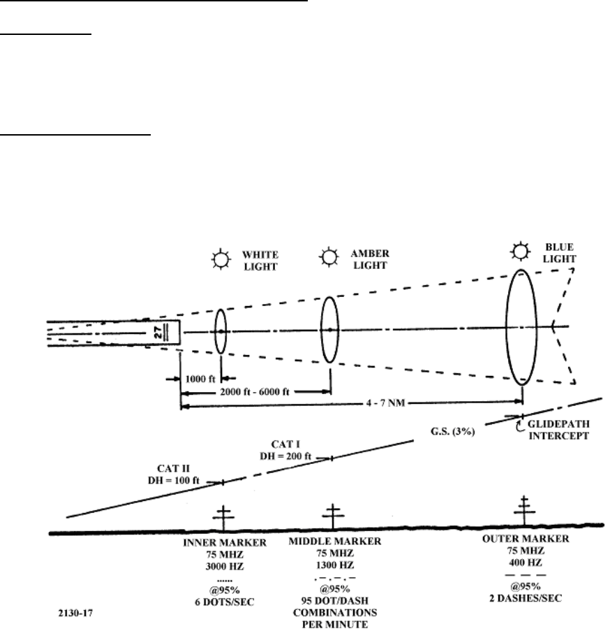
Refer to Figure 1-1. Marker Beacons are used to provide an aircraft both an aural and visual indication of station passage.
Station identification is provided by both a modulation frequency and keying code. The Marker Beacon transmits an
upward-directed elliptical signal of information at a frequency of 75-MHz. Each Marker Beacon signal is amplitude
modulated by an audio tone which is Morse code keyed. Both the audio tone frequency and the keying are distinctive
according to the marker's location.
Figure 1-1 Marker Beacon
The Marker Beacon is used in two distinct operational environments: en-route or terminal facility. Terminal application
Marker Beacons or, as they are more commonly called, Instrument Landing System (ILS) Marker Beacons, are located
along the extended runway centerline and are used as distance-to-touchdown indicators to indicate significant points
along an instrument approach path. These types are classified as the Outer, Middle, and Inner Marker Beacon systems.
Fan Marker Beacons may also be associated with the ILS to serve as a localizer step down fix or Missed Approach Point
(MAP) for circling approaches to secondary airports.

MODEL 2130 MARKER BEACON
1-2 Rev. A April, 2005
This document contains proprietary information and such information may not be disclosed to others for any
purposes without written permission from SELEX Sistemi Integrati Inc.
When used for en route applications, the Marker Beacon is configured as a fan marker. It can be used with other
Navigational Aid equipment and its use depends upon instrument flight procedural applications.
For ILS operation, an outer marker is typically located 4 nautical miles from the runway threshold; this location normally
coincides with the point on the ILS approach at which the glide slope altitude equals the intercept altitude. A middle
marker is typically located 3,500 feet from the runway threshold; this location normally coincides with the point on the
glide path at which the Decision Height (DH) is located for Category I operations 200 feet above the touchdown zone
elevation. The inner marker is only installed for Category II and III ILS approaches, and is located approximately 1000 feet
from the runway approach threshold, coinciding with the nominal Category II decision height of 100 feet.
The inner, middle and outer marker antennas are single five element Yagis.
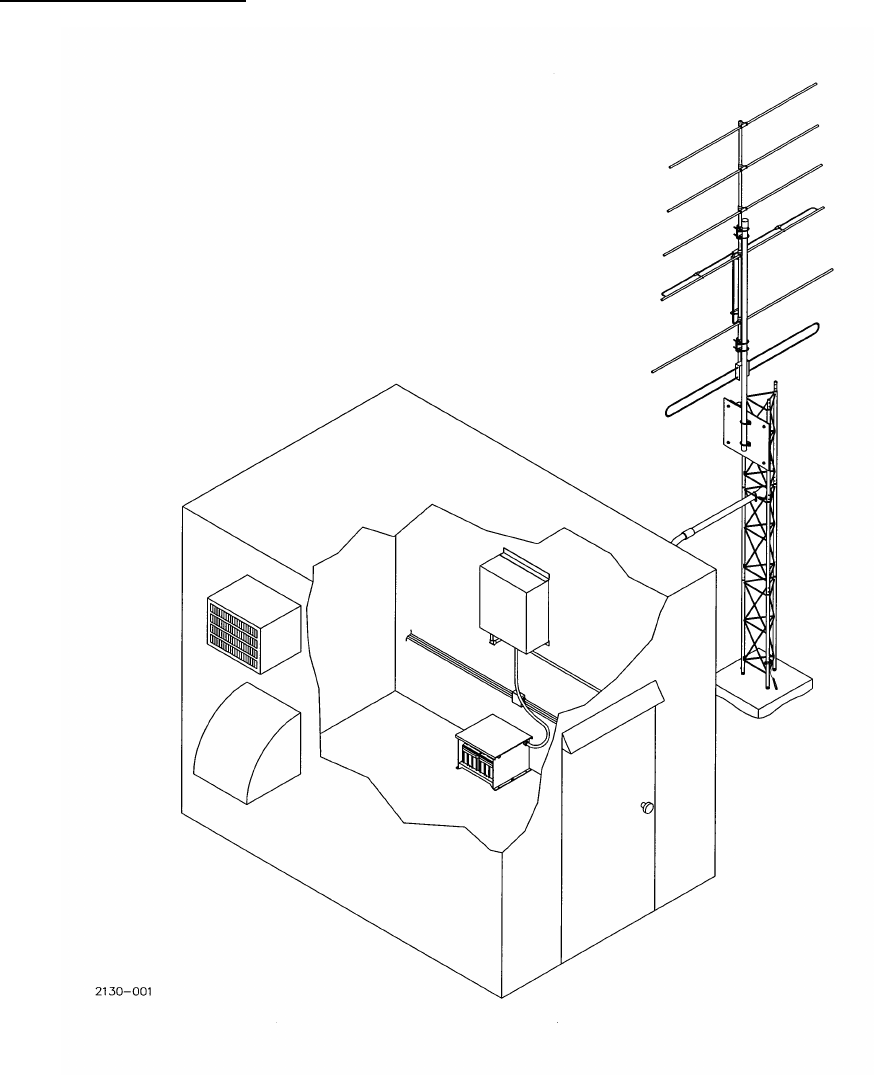
The Marker Beacon (Figure 1-2) is of modular design and completely solid-state. Both single equipment and dual
equipment transmitters are available. Battery backup (Figure 1-6) is optional and provides power in case of primary AC
power failure. Operating control of the Marker Beacon system is by a Portable Maintenance Data Terminal (PMDT) The
PMDT is an IBM compatible personal computer running SELEX SISTEMI INTEGRATI INC. proprietary application
software. The two antenna configurations (pole and tower) are shown in Figure 1-4.
Microprocessor-controlled monitoring and built-in test equipment are an integral part of the equipment. This allows
continuous monitoring of all required parameters as well as the testing, control, and display of voltages, currents, and
frequencies.
The Marker Beacon can be remotely monitored through:
a. Dedicated telephone lines to the Model 2238 Remote Status Control Unit.
b. Optional radio link operating at either 900 MHz or 2.4 GHz.
c. Remote Maintenance Monitoring (RMM) - Switched telephone lines and modem integrated within the 2130 Marker
Beacon allow for interface to remote monitoring points using the PMDT software.
1.2.1 Monitoring Systems
A high integrity integral monitoring system incorporated in the Marker Beacon system to provide fault detection by
monitoring the transmitted signals and initiating automatic station transfer to a standby transmitter or shutdown in the
event of an out-of-tolerance condition.
Dual, parallel monitoring channels are included for measurement of important signal parameters for the On-the-Air
Transmitter and Standby Transmitter.
Independently adjustable pre-alarm (maintenance alert) indications are included for all executive monitoring parameters.
All executive and maintenance alarm indications are provided both locally at the station and remotely through the Remote
Maintenance Monitoring (RMM) system.
Integrity of the monitors is assured by certification testing using a built-in Test Generator.
Failsafe design of the monitors ensures the removal of Navigation and Identification signals and the transmission of a
warning signal to the remote control and monitoring points in the event of a failure in the monitoring system itself.
Failsafe testing of the monitors and control circuits has been performed to verify that any single failure of a component,
open or short in the monitor(s) or control circuit will either result directly in an alarm condition, or will not alter any alarm
threshold level to allow an out-of-tolerance condition to occur without detection.
The monitoring system includes a bypass capability to disable the automatic station control action during adjustment and
maintenance. Front panel amber "bypass" and "alarm" lights are illuminated any time the integral or standby transmitter
MODEL 2130 MARKER BEACON
Rev. A April, 2005 1-3
This document contains proprietary information and such information may not be disclosed to others for any
purposes without written permission from SELEX Sistemi Integrati Inc.
is bypassed.

MODEL 2130 MARKER BEACON
1-4 Rev. A April, 2005
This document contains proprietary information and such information may not be disclosed to others for any
purposes without written permission from SELEX Sistemi Integrati Inc.
All monitored and internally measured system parameters are available for display via the station RS-232 communications
port and the Portable Maintenance Data Terminal (PMDT). The parameters are also available remotely through the
Remote Maintenance Monitoring (RMM) system.
1.2.2 Station Control System
The station control system provides for manual control of the station during maintenance operations and for automatic
control during unattended operation.
The Local Control Unit provides the following system features:
a. Local On/Off control and status indication of the transmitting equipment.
b. Selection of which transmitter operates as Main and which operates as Standby.
c. Monitor bypass capability with indications for the Integral and Standby Transmitter monitoring systems.
d. Provisions for either Local or Remote control of the transmitting equipment.
e. System reset capability.
f. Automatic transfer capability from the Main to the Standby transmitting equipment (or shut down for single
transmitter) in response to monitor alarm conditions following an adjustable preset alarm delay period. The Standby
transmitter is operated in the "hot standby" mode for CAT III stations, and may be operated as either a "hot or cold"
standby for CAT II or CAT I operations. When operated in the "hot standby" mode, the standby transmitter is
placed on line immediately at the end of the alarm delay period. When operated in the "cold standby" mode, the
standby transmitter is activated following a preset alarm delay period (20 seconds, minimum).
g. Two automatic station restart attempts following shutdown; the first after a time delay of 50 seconds, and the second
after a fixed delay of 15 minutes. If either restart attempt is successful, all delay timers are reset to their original
condition. If the restart is not successful then a manual local or remote restart is required. If an alarm occurs the alarm
indicator at the RCSU is activated.
h. Automatic station transfer to and from the no-break standby battery system in the event of a primary AC power
failure and subsequent restoration; and automatic turn-on following restoration of primary AC power should the
standby battery system be depleted. Batteries automatically recharge on restoration of primary power.
i. In addition to the control features above, system control and monitoring functions as well as verification and
adjustment of proper transmitting and monitoring parameters are available using Windows™ based displays via an
RS-232 communications port on the transmitter cabinet and a Portable Maintenance Data Terminal (PMDT). The
system is password controlled such that system adjustments are possible only with entry of the proper security
codes. A second RS-232 communications port is connected to a modem for system operation and monitoring via a
dial-up telephone line to a remote location.
1.2.3 Remote Control and Status Equipment (Optional)
An optional Remote Status and Control Unit (RCSU) and up to three Remote Status Units (RSU) are available for remote
control and status monitoring of the Marker Beacon station.. Provisions are included for On/Off status monitoring of
auxiliary transmitting equipment which may be installed at the Marker Beacon station.
The RCSU is a computer using Windows™ type displays and is designed for installation in a control tower equipment
room. The RSU/s are driven by the RCSU and are designed for installation at controller positions within the tower.
Features of the RCSU system include:
a. On/Off, and Transfer control for the Marker Beacon.
b. Status indications on the RCSU and RSU(s) for the Marker Beacon facility.
c. Interlock capability on the primary RSU for Localizer, Glideslope, Marker Beacon and DME systems located on
opposite ends of the same runway. Runway-Selected indication is provided on all RSUs.
d. Remote access to the RMM system on any of the Localizer, Glideslope or VOR stations through the RCSU computer
via modem or TCP/IP network.
e. Only a single dedicated control line is required from the RCSU to each of the connected stations.

MODEL 2130 MARKER BEACON
Rev. A April, 2005 1-5
This document contains proprietary information and such information may not be disclosed to others for any
purposes without written permission from SELEX Sistemi Integrati Inc.
1.2.4 Remote Maintenance Monitoring System
The integral Remote Maintenance Monitoring (RMM) system operates in conjunction with the Local Control Unit and
Portable Maintenance Data Terminal (PMDT). It consists of the various embedded sensors, internal monitoring points,
microcomputers and built-in test equipment to remotely monitor, control, record and certify proper operation of the
Marker Beacon subsystems.
In addition to local access to the RMM system through the built-in RS-232 port, and remote RMM access through a dial-
up telephone line and the Portable Maintenance Data Terminal (PMDT), the Remote Control and Status Unit (RCSU)
computer and modem may be utilized for dial-up access to the RMM system.
All components of the RMM subsystem meet the requirements for Class A computing devices in accordance with
subpart B, Part 15, and certification in accordance with subpart J, Part 2 of the FCC Rules and Regulations.
1.2.5 RMM Functions
The RMM system provides the following key functions:
a. System control.
b. Adjustment of transmitting parameters on the Marker Beacon system. For security, this feature is available only at
the respective station by default. Each station may be optionally configured to allow adjustment from a remote
location.
c. Monitoring of system performance and certification parameters. Compares the outputs of each of the monitoring
devices to determine alarm and alert status by comparing the monitored values to pre-determined limits.
d. Adjustment of all alarm and alert monitoring limits. For security, this feature is available only at the respective
Localizer or Glideslope station by default. Each station may be optionally configured to allow adjustment from a
remote location.
e. Monitor Certification.
f. Storage of monitor alert and alarm data.
g. System Fault Diagnostic routines with result storage and reporting for Localizer and Glideslope systems. On-Air
diagnostic routines for the Localizer and Glideslope stations may be initiated either locally at the station or remotely.
Diagnostic routines which require the respective station to be NOTAMED out of service must be run locally at the
station by default. Each station may be optionally configured to allow all diagnostic routines to be run from a remote
location.
h. Monitoring of routine maintenance parameters including voltages and currents and VSWR.
i. Monitoring of environmental parameters (when optional sensors are installed).
j. Monitoring of primary AC power applied to the system.
k. Monitoring of standby battery voltage and current.
l. Printing of menus and all display/parameter values.

MODEL 2130 MARKER BEACON
1-6 Rev. A April, 2005
This document contains proprietary information and such information may not be disclosed to others for any
purposes without written permission from SELEX Sistemi Integrati Inc.
1.2.6 RMM Security
The RMM system is designed in accordance with FAA Order 6000.32 (Security Requirements for Remote Access of NAS
Facilities), and FAA Specification FAA-E-2852/b (Category II/III Instrument Landing System) and features a 4-level
security system to insure only authorized personnel have access to the various system functions and commands. The
four password controlled levels are:
Level 1 - Allows access for display-only of system status, configuration and monitored system
parameters. No control functions are available at this level.
Level 1 access requires a general User ID without a Password.
Level 2 - Level 1 access plus the ability to run tests or diagnostics and make adjustments which do not
affect the integrity of the system.
Level 2 access requires a unique User ID and Password.
Level 3 - Full access to all functions available in the system, except assignment of user ID’s and
Passwords.
Level 3 requires a unique User ID and Password.
Level 4 - Full system access to all functions available in the system, including assignment of user ID's
and passwords.
Level 4 access requires a user to be logged-in at any level and enter a second unprompted
password.
Error flags are provided for invalid User ID or Password entry.
Protection against unsuccessful log-on is provided in the system by either of the following time-out events:
a. Three unsuccessful attempts to enter either a valid User ID or password results in automatic disconnection of the
terminal port or dial up-modem for three minutes.
b. If no activity occurs for a period of 15 minutes, the user is automatically logged off and, if a dial-up modem is
connected, the modem disconnects from the telephone line.
1.2.7 Environmental Monitoring
Optional environmental monitoring is available for the Marker Beacon stations. Inside and outside temperature, smoke,
and intrusion sensors are included which alert the maintenance technician to conditions that may affect the on-air
availability of these critical systems.
MODEL 2130 MARKER BEACON
Rev. A April, 2005 1-7
This document contains proprietary information and such information may not be disclosed to others for any
purposes without written permission from SELEX Sistemi Integrati Inc.
1.2.8 Transmitter Description
Figure 1-2 Marker Beacon System
MODEL 2130 MARKER BEACON
1-8 Rev. A April, 2005
This document contains proprietary information and such information may not be disclosed to others for any
purposes without written permission from SELEX Sistemi Integrati Inc.
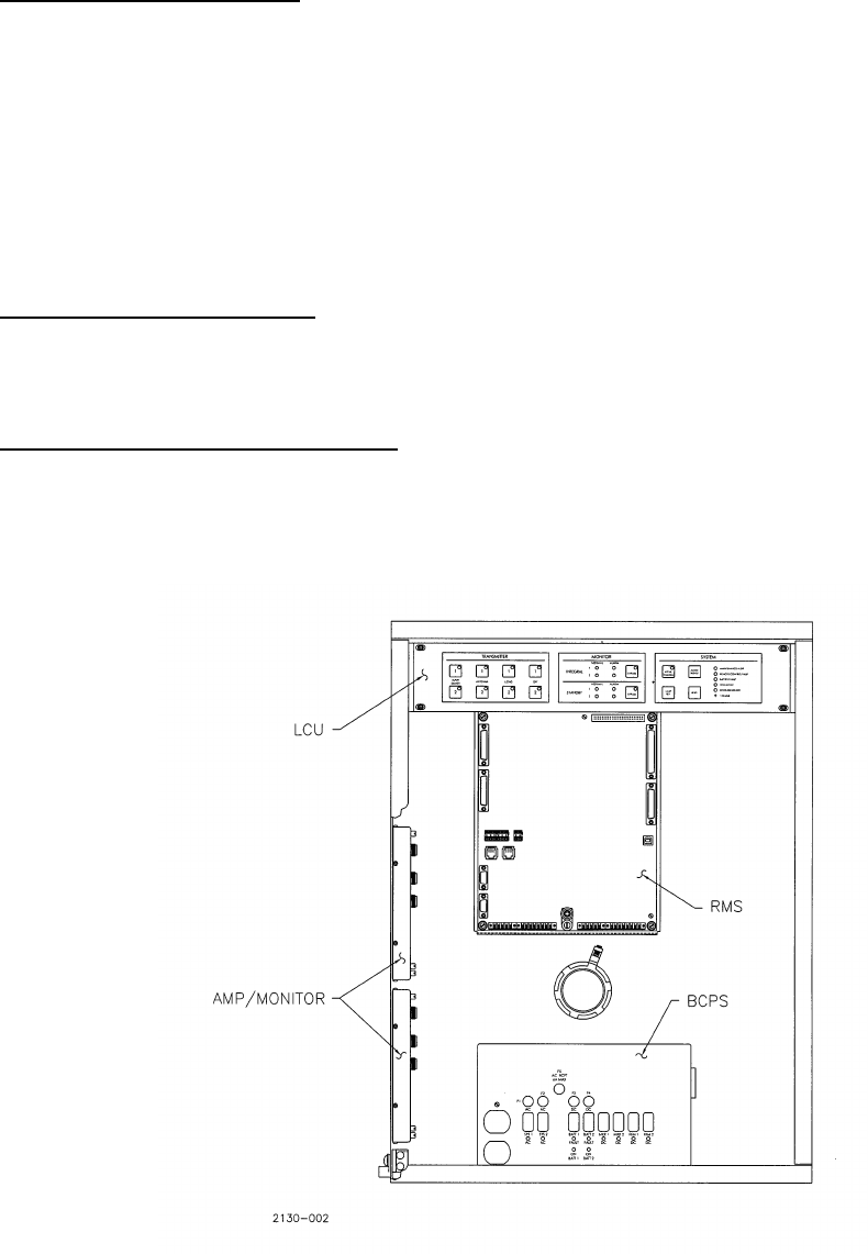
1.2.8.1 Cabinet Assembly (Unit 1)
Refer to Figure 1-3. The cabinet is 24 inches high, 21 inches wide and 10 inches deep. The cabinet is an aluminum metal
housing for the electronics of the Marker Beacon system. This cabinet also accommodates one or two Far Field Monitor
receivers. When a FFM alone is required the Marker Beacon electronics are not provided. Up to two Marker Beacon
transmitters and two Far Field Monitors can be located within the cabinet at the same time. There are no vents due to the
low power consumption and low power dissipation within the Marker Beacon cabinet. A hinged lockable front door on
the front provides access to the assemblies and circuit card assemblies (CCAs). The cabinet is a welded assembly with
EMI gasket material to reduce stray radiation from the cabinet.
The cabinet contains the AC and DC primary controls, provisions for interconnect between primary power, and RF
antenna connections.
1.2.8.2 RMS Processor CCA (1A4)
The RMS Processor CCA is located on the rear wall of the cabinet. The RMS CCA contains the system software and
performs control, monitoring, and test functions under processor control. The RMS CCA connects to the main wiring
harness through the 37 pin D connector and to one or two amplifier/monitor assemblies through 25 pin D connectors.
1.2.8.3 Local Control Unit (LCU) CCA (1A3)
The Local Control Unit CCA is located on the top control panel inside the Marker Beacon Cabinet. The 012143-1001 Local
Control Unit CCA is attached to the rear of the front panel. This unit provides Local ON/ OFF control as well as automatic
changeover control. The LCU also includes the transfer relays required for selecting the transmitter attached to the
Marker Beacon antenna system. In a dual system the standby transmitter is directed into an attenuator and fed back to
each Amplifier/ Monitor for Standby transmitter monitoring.
Figure 1-3 Marker Beacon Equipment Cabinet, Interior View

MODEL 2130 MARKER BEACON
Rev. A April, 2005 1-9
This document contains proprietary information and such information may not be disclosed to others for any
purposes without written permission from SELEX Sistemi Integrati Inc.
1.2.8.4 Power Control Panel Assembly (1A1)
The Power Control Panel assembly is located within the cabinet housing and measures 11 inches wide by 8-1/4 inches
long by 3 inches deep. This assembly contains the AC power switches, DC power switches and battery charging power
supplies. It provides 15 VDC from the AC primary input, for the Marker Beacon electronics and charging voltage/current
for the optional backup battery supply. An AC outlet with fuse is provided on the front of the assembly. The Battery
Charging Power Supply (BCPS) circuit card assembly is attached to the back side of the Power Control Panel Assembly.
The BCPS is common to both the Marker Beacon and FFM. The BCPS with the associated power supply provides
sufficient capacity to power both the Marker Beacon and FFM electronics and to recharge the battery in the required time.
1.2.8.5 Power Supply Assembly (1A1A2)
The Power Supply assembly is located within the BCPS enclosure at the bottom of the cabinet in a ventilated aluminum
housing. This power supply is a 15 Volt DC assembly that operates on universal AC input voltage. The selection of AC
input is automatically selected; no jumpers required.
1.2.8.6 RF Power Amplifier /Monitor CCA (1A2/1A5)
The RF Power Amplifier CCA is located on the left inside wall of the cabinet. For a single Marker Beacon the 1A2
assembly is located in the upper position. For a dual transmitter the second amplifier/ monitor (1A5) is installed in the
lower position. The RF Power Amplifier/Monitor CCA provides RF tone generator, modulator and identification keying.
The assembly includes a three channel frequency synthesizer used to offset the output frequency +/- 4 kHz from the
nominal channel if desired. The power amplifier/ monitor processes the RF monitor signal from the antenna and connects
to the main wiring harness through a 25 pin connector.
1.2.8.7 Transmitting Antennas
Refer to Figure 1-4. There are two transmitting antenna configurations used to provide the proper patterns at the Marker
Beacon sites. A single Yagi is used for the inner marker and the middle/outer marker. The inner marker antenna is
mounted on a self supporting aluminum pole. The aluminum pole has a frangible joint located 3 inches above ground level
and is designed to collapse under impact from an aircraft imparting 4000 lbs-force of shear force parallel to the runway
centerline, with minimal damage to the aircraft. The middle and outer marker antennas are mounted on galvanized steel
towers.
1.2.8.8 Portable Maintenance Data Terminal (PMDT) (Optional)
Refer to Figure 1-5. This video terminal consists of a laptop computer and is used for local control and maintenance of the
Marker Beacon. The PMDT is attached to the RMS CCA located on the back wall of the cabinet. The operation of the
PMDT software is described in Section 3 of this manual.
1.2.8.9 Battery Backup Unit (Unit 4)
Refer to Figure 1-6. The battery backup unit consists of one floor mounted battery enclosure which contains one lead-
acid maintenance-free battery for single equipment and two batteries for dual equipment. Additional backup capacity can
be achieved by adding additional units. The battery backup unit is shared with a Far Field Monitor receiver as they reside
in the same enclosure. Marker Beacon 1 and FFM 1 share a battery set and for dual equipment, Marker Beacon 2 and FFM
2 share a battery set. The battery backup rack is manufactured from aluminum that is gold iridized and painted to provide
adequate protection against damage caused by electrolyte leakage. A cover is provided to allow maintenance access and
to prevent accidental shorting of the battery terminals. The battery rack is open in the front and rear to provide visual
inspection and air flow for ventilation.
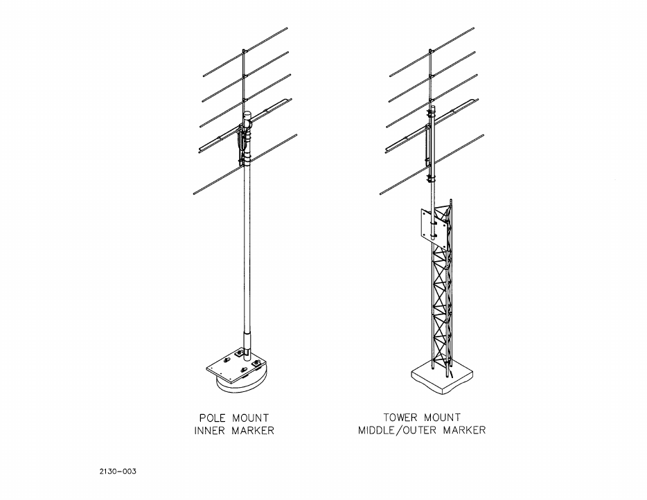
MODEL 2130 MARKER BEACON
1-10 Rev. A April, 2005
This document contains proprietary information and such information may not be disclosed to others for any
purposes without written permission from SELEX Sistemi Integrati Inc.
Figure 1-4 Marker Beacon Transmitting Antennas

MODEL 2130 MARKER BEACON
Rev. A April, 2005 1-11
This document contains proprietary information and such information may not be disclosed to others for any
purposes without written permission from SELEX Sistemi Integrati Inc.
Figure 1-5 Portable Maintenance Data Terminal (PMDT) – Optional
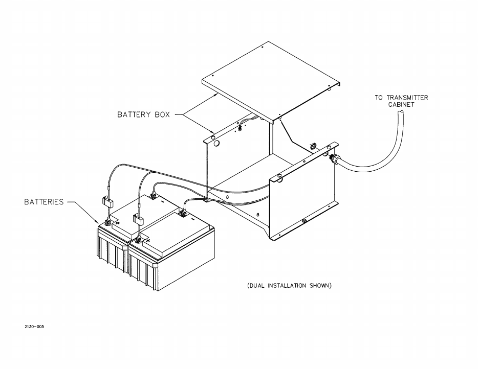
MODEL 2130 MARKER BEACON
1-12 Rev. A April, 2005
This document contains proprietary information and such information may not be disclosed to others for any
purposes without written permission from SELEX Sistemi Integrati Inc.
Figure 1-6 Battery Backup Unit

MODEL 2130 MARKER BEACON
Rev. A April, 2005 1-13
This document contains proprietary information and such information may not be disclosed to others for any
purposes without written permission from SELEX Sistemi Integrati Inc.
1.3 Equipment Specifications Data
The equipment specification data is listed in Table 1-1.
Table 1-1 Equipment Specifications Data
Equipment Manufacturer SELEX Sistemi Integrati Inc.
Equipment Type Marker Beacon Electronics Subsystem
Model Number 2130
Power Output Adjustable 50 mW to 2.5 W
Carrier Frequency Synthesizer Controlled, 3 Channels
74.996-MHz
75.000-MHz
75.004-MHz
Antenna Gain (over dipole) 9.0 dB
Frequency Tolerance ∀0.0005%
Spurious Emissions ∃ 50 dB below carrier
Emission Modes 8A2, 2.6A2, 6A2
Modulation Capability 10% to 100%, adjustable
Modulation Frequencies 400-Hz, 1300-Hz, 3000-Hz
Audio Distortion Does not exceed 5%
Keying Characteristics Selectable:
Outer Marker
Middle Marker
Inner Marker
Keying Control Normal
Continuous
Off
Polarization Horizontal
Inner Marker Antenna Height = 7 feet
Inner Marker Frangible Break Height 3 inches
Coverage per ICAO Annex 10
Remote Status Monitoring Capability Remote Status Control System (RSCS)
Remote Maintenance Monitoring (RMM)
MODEL 2130 MARKER BEACON
1-14 Rev. A April, 2005
This document contains proprietary information and such information may not be disclosed to others for any
purposes without written permission from SELEX Sistemi Integrati Inc.
Table 1-1 Equipment Specifications Data (Cont.)
Environmental:
Temperature -50ΕC to +70ΕC (Outdoor equipment)
-10ΕC to +55ΕC (Indoor equipment)
Relative Humidity 0 to 95%
Altitude 0 to 15,000 feet (4572 m)
Duty Cycle Continuous, unattended
Primary Power 90-264 VA C, 47 to 63 Hz, Single Phase
12 VDC +15% (built-in charger)
Power Consumption 280 VA (Max)
75 Wdc
Monitored Parameters -3 dB RF level (Adjustable)
Low % modulation (Adjustable)
External RF level (Adjustable)
Loss of keying, continuous tone
VSWR
Carrier Output Power Stability Rated Power ±0.5 dB
Modulation Stability 95 ± 5 percent over the full range of service conditions.
System Shutdown Adjustable 5 to 15 seconds
Restart System
First time 50 ± 5 Seconds
Second time 15 minutes ± 30 seconds after the initial shutdown.
Built-in Test Equipment Digital Voltmeter; Digital Wattmeter; VSWR display; Primary voltage and
current; Battery-charging voltage and current; Modulation %;
Temperature;
Battery-Charging Current 2 A (nominal)
Battery-Charging Voltage 13.7 VDC
MODEL 2130 MARKER BEACON
Rev. A April, 2005 1-15
This document contains proprietary information and such information may not be disclosed to others for any
purposes without written permission from SELEX Sistemi Integrati Inc.
Table 1-1 Equipment Specifications Data (Cont.)
Spare Inputs and Outputs
Analog Inputs 4
Range Bipolar -5.0000 to +5.0000 with respect to ground
Accuracy ±5% or reading up to ±0.01 volt.
Resolution = 1 part in 1000
Impedance = 20 KOhms
Digital Inputs 2
Low 0.0 to +0.8 volts (TTL low)
High +2.0 to +5.5 volts (TTL high)
Alert threshold Programmable through the PMDT as High or Low
Digital Outputs 4
Low 0.0 to +0.8 volts (TTL low)
High +2.0 to +5.5 volts (TTL high)
Load = 24 ma when at TTL Low

MODEL 2130 MARKER BEACON
1-16 Rev. A April, 2005
This document contains proprietary information and such information may not be disclosed to others for any
purposes without written permission from SELEX Sistemi Integrati Inc.
1.4 Equipment and Accessories Supplied
Table 1-2 is a list of all equipment and accessories supplied.
Table 1-2 Equipment and Accessories Supplied
Quantity Description Part Number
1 Marker Beacon Transmitter System 002130-0101
(120/240V) Single Equipment:
1 Marker Beacon Transmitter System 002130-0102
(120/240V) Dual Equipment:
1 Installation Kit 470597-0001
1 Battery Backup Kit, Single Eqpt (w/Batt) 470595-0001
Battery Backup Kit, Dual Eqpt, (w/Batt) 470595-0002
Battery Backup Kit, Single Eqpt (w/o Batt) 470595-0003
Battery Backup Kit, Dual Eqpt (w/o Batt) 470595-0004
1 Transmitting Antenna Kit, Tower Mount 470592-0001
1 Transmitting Antenna Kit, Pole Mount 470596-0001
1 Exterior Interface Kit, Inner Marker 470593-0001
1 Exterior Interface Kit, Middle/Outer Marker 470594-0001
1 Antenna Cable Kit 470598-0001
1 Civil Installation Kit, Inner Marker 470558-0001
1 Civil Installation Kit, Middle/Outer Marker 470252-0001
2 Operations and Maintenance Manual 572130-0001

MODEL 2130 MARKER BEACON
Rev. A April, 2005 1-17
This document contains proprietary information and such information may not be disclosed to others for any
purposes without written permission from SELEX Sistemi Integrati Inc.
1.5 Equipment Required but not Supplied
Table 1-3 is a list of test equipment that is not supplied but is required to make the equipment operational.
Table 1-3 Equipment Required But Not Supplied
Required Suggested
Name Characteristics Equipment
Oscilloscope Bandwidth: to 60-MHz
Voltage Range: [0.1 to 10V/Div.]
Input impedance: 1 megohms Tektronix TDS1002
Frequency
Counter/Timer 400-Hz to 75-MHz B & K 1856C
Wattmeter
RF Power: 0.1 to 5W @ Bird Thruline Wattmeter
75-MHz with 5W element.
Multimeter AC, DC, Ohms Fluke 175
1.6 Optional Equipment
Table 1-4 is a list of optional equipment.
Table 1-4 Optional Equipment
Quantity Description Part Number
1 Shelter 6' x 8' 890121-4010, or
890011-1010
1 Antenna Splitter 470601-0001
1 Internal Grounding Kit 470557-0001
1 Lightning Protection Kit 470223-0004
1 Shelter grounding kit 470225-0001
1 Remote Status Control System 002238-0312
1 Portable Maintenance Data Terminal (PMDT) 470360-0001
1 Radio Link kit (900 MHZ) 470602-0001
1 Radio Link kit (2.4 GHz) 470602-0002
1 Communication Antenna Kit 470090-0001
1 Environmental Sensor kit 470357-0001
MODEL 2130 MARKER BEACON
1-18 Rev. A April, 2005
This document contains proprietary information and such information may not be disclosed to others for any
purposes without written permission from SELEX Sistemi Integrati Inc.

MODEL 2130 MARKER BEACON
Rev. A April, 2005 2-1
This document contains proprietary information and such information may not be disclosed to others for any
purposes without written permission from SELEX Sistemi Integrati Inc.
2. TECHNICAL DESCRIPTION
2.1 Introduction
The Marker Beacon is comprised of a Local Control Unit, RMS Processor, one Amplifier/ Monitor Assembly for single
equipment or two Amplifier/Monitor Assemblies for dual equipment. In addition the power panel assembly contains the
Battery Charging Power Supply (BCPS) with one power supply for single equipment and two power supplies for dual
equipment. The Marker Beacon is provided with battery backup capability through the BCPS function.
The Amplifier/ Monitor Assembly provides frequency synthesizer for signal generation, an RF amplifier and monitor
functions.
2.2 Antenna Operation
The required coverage pattern of each Marker Beacon is elliptically shaped as defined in Table 2-1, with the minor axis
oriented along the course centerline.
The Marker Beacon transmitter power is capable of being adjusted to provide the required signal (1700 microvolts) within
the bounds of the minimum and maximum dimensions of the axes.
The vertical coverage of the Marker Beacon is such that the received signal rises to 3000 microvolts/meter near the center
of the ellipse.
Table 2-1 Marker Beacon Coverage Pattern
Measured distance along course
Centerline (Minor axis)
Measured distance along 75 uA lines (Major
axis)
Marker Beacon
Type
Minimum (ft) Maximum (ft) Minimum (ft) Maximum (ft)
Inner 340 660 Not Measured Not Measured
Middle 675 1325 350 1325
Outer 1350 4000 700 4000
The field strength within the coverage area meets the following requirements:
a. Provides an elliptical radiation pattern with its minor axis parallel to the course line when cut by a horizontal plane
with a minimum major-to-minor axis ratio of 1.5 to 1.0. Coverage is measured along the Localizer course line while
descending along the commissioned glide path. With the Marker Beacon power adjusted for the desired coverage
pattern, signal strength sufficient to provide an indication on the Marker Beacon receiver extends at least 3000 feet
above the station.
b. The major axis width is sufficient to provide sufficient signal strength to a standard Marker Beacon receiver at the 75
microampere edge-of-course line at the altitude established by the instrument approach procedure established for the
runway.
2.3 Marker Beacon Transmitter Theory of Operation
2.3.1 Marker Beacon Amplifier/ Monitor Theory of Operation
The Marker Beacon Amplifier/Monitor CCA performs the RF signal generation and monitoring for the Marker Beacon
transmitter cabinet. There is one Amplifier/ Monitor for single equipment and two provided for dual equipment
configuration. The Amplifier/Monitor CCA is located on the inside left wall of the Marker Beacon cabinet. For a single
configuration the transmitter output cable and Integral monitor cable connect directly to the exterior interface box. For a
dual transmitter configuration the transmitter output connects to the LCU CCA.
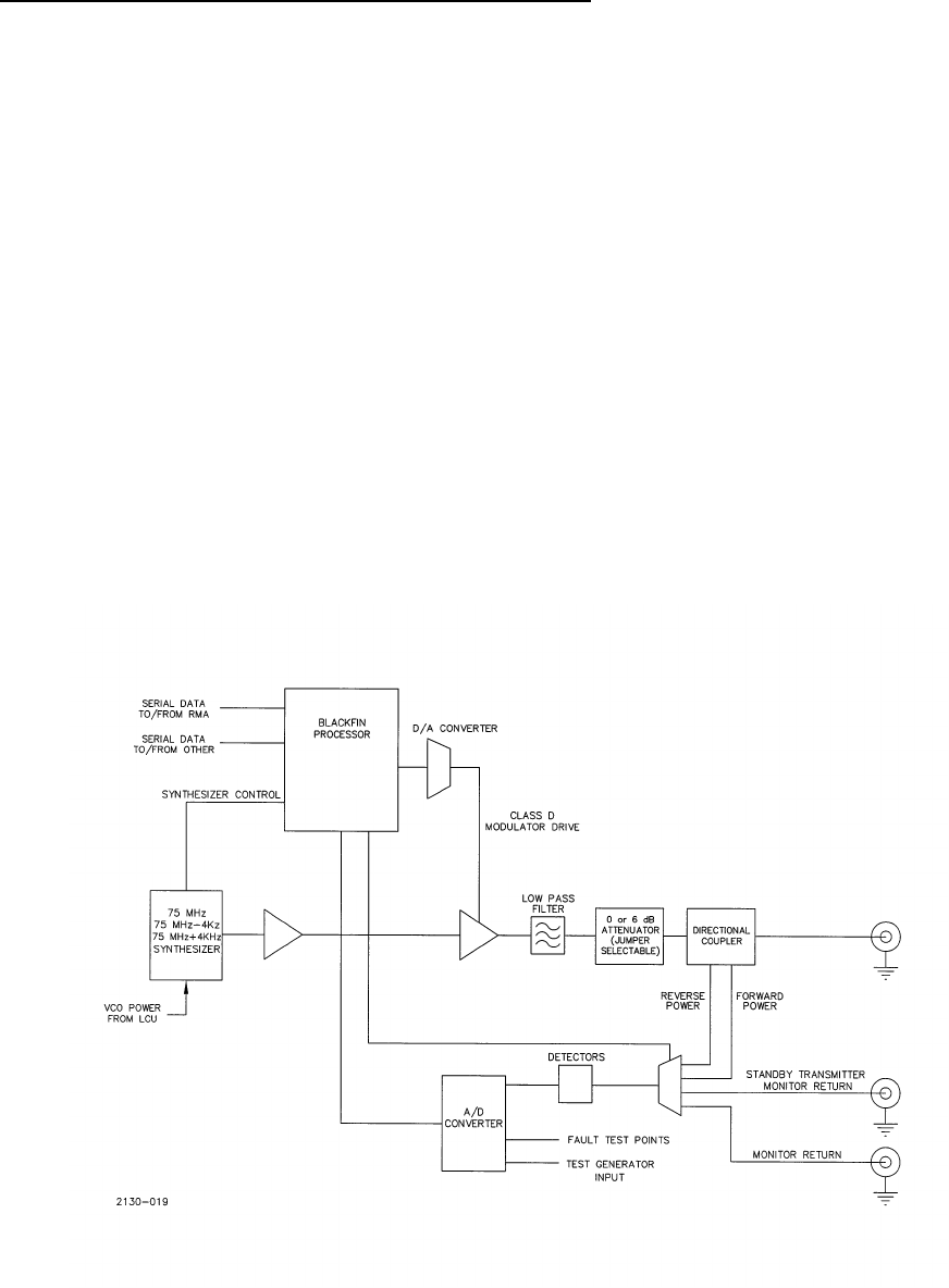
MODEL 2130 MARKER BEACON
2-2 Rev. A April, 2005
This document contains proprietary information and such information may not be disclosed to others for any
purposes without written permission from SELEX Sistemi Integrati Inc.
2.3.1.1 Marker Beacon Amplifier/ Monitor Block Diagram Theory
Refer to Figure 2-1. The Amplifier/Monitor includes a frequency synthesizer that can be programmed to 75 MHz. In
addition the frequency can be set to 4 kHz higher or 4 kHz lower than 75 MHz. The synthesizer channel is set from the
PMDT interface.
The output of the synthesizer is amplified in two stages to obtain 2.5 Watts. A low pass filter in the output rejects
harmonics and high frequency spurious signals. The low pass filter is followed by a directional coupler for monitoring
forward and reverse power. A jumper selectable 6 dB attenuator allows for the amplifier to operate down to the lower
power level of the Inner Marker Beacon.
The RF amplifier is modulated class A.
The directional coupler forward and reverse power signals are fed back into an IF detector and into an A/D converter for
measurement. In addition the monitor return from the antenna and the standby transmitter signal from the LCU transfer
logic is fed into the detector and the A/D converter for processing.
The microprocessor is an Analog Devices Blackfin, BF532. This is a 16 bit processor running at 400 MHz internally. This
is possible by an internal phase locked loop. Flash memory is provided to store program information A non-volatile
memory that provides long term storage of setup information is used along with a real-time clock crystal in conjunction
with the internal used to provide day/date/time information.
Setup information is provided to the Amplifier/ Monitor through the serial communications channel to the RMS CCA. The
RMS communicates to the PMDT and any setup information is passed to the Amplifier/ Monitor from the RMS.
Figure 2-1 Amplifier/Monitor Block Diagram
MODEL 2130 MARKER BEACON
Rev. A April, 2005 2-3
This document contains proprietary information and such information may not be disclosed to others for any
purposes without written permission from SELEX Sistemi Integrati Inc.

MODEL 2130 MARKER BEACON
2-4 Rev. A April, 2005
This document contains proprietary information and such information may not be disclosed to others for any
purposes without written permission from SELEX Sistemi Integrati Inc.
2.3.1.2 Marker Beacon Amplifier/ Monitor Detailed Circuit Theory
2.3.1.2.1 Power Supply
Refer to Figure 11-12 Sheet 2. The power for the Amplifier/Monitor enters on J3 pins 21, 22, and 23. The 12 volts is
converted to 5 VDC by DC-DC Converter PS1. The output of PS1 enters U19, a linear voltage converter that drops the
voltage to 3.3 VDC and is labeled DVCC for use as the digital supply voltage.
The 12 VDC also enters U20 where it is converted by a linear converter to +5 VDC and labeled VCC. This voltage powers
the TXCO, U5.
The 12 VDC is converted to +5 VDC by U16. This 5 VDC is used by RF amplifiers U17 and U18 as the supply voltage for
operation. Separate power supplies are used to provide noise immunity from one function of the amplifier to another.
2.3.1.2.2 Synthesizer
Refer to Figure 11-12 sheet 2. Integrated circuit U13 acts as the loop controller for the synthesizer circuit. Microprocessor
U8 sets the channel information into U13 by serial shifting data into the circuit. Data enters on the line marked
Synth_data. The data is clocked into the circuit by Synth_clock. When programming is complete Synth_LE is toggled.
The signal Synth_lock when low indicates that the synthesizer is locked on frequency.
The loop filter is comprised of C54, R22, C56, R21 and C58. The output of the loop filter controls the VCO. The voltage
into the tune input sets the output frequency of the VCO U15. Power for the VCO enters on J3 pin 20. This voltage
originates on the LCU and is one of the duplicated methods to disable the transmitter. The VCO power is regulated to 10
volts DC by low voltage drop regulator U14. The output of U14 is filtered by caps C57, C113, and C62 and enters the VCO
U15.
The output of the VCO is attenuated by R29, R30 and R32 and amplified by U17. The output of U17 is split in two by R34,
R37 and R35 resulting in a 6 dB power loss. The combination of R35, R36 and R28 forms another attenuator prior to
entering the VCO controller U13 where the signal is divided, compared against the reference frequency and the VCO
control voltage corrected.
The other output of the power divider formed by R34, R35 and R37 enters U18 and amplified. Resistors R42, R43 and R46
form an attenuator prior to entering U21. U21 amplifies the signal and provides an output level of approximately 10 mW
and is marked PA_DRIVE.
Refer to Figure 11-12 sheet 4. The modulation for the RF amplifiers originates from U8 microprocessor. Serial data is
transferred to D/A converter U37. The signal from U37 is low pass filtered by U24B and U24C. Op Amp U24A combines
the detected signal from U26A and U24A with the modulation from U24C. U24A drives FETs Q4, Q5 and Q10 as a class A
Modulator. Op Amp U30D takes the detected signal and amplifies to TTL level for monitoring.
FET Q2 is the first amplifier stage that provides approximately 10 dB of gain. The input from the frequency synthesizer
section enters at PA_DRIVE. The modulation enters through R51 and L13. The gate bias voltage enters through R52. The
gate voltage is set by potentiometer R54 and R53 and derived from a precise voltage set by R55 and zener diode CR7.
Capacitors C99 and C101 filter this 7.5 VDC to eliminate noise.

MODEL 2130 MARKER BEACON
Rev. A April, 2005 2-5
This document contains proprietary information and such information may not be disclosed to others for any
purposes without written permission from SELEX Sistemi Integrati Inc.
The RF output of Q2 enters the gate of Q3 where it is amplified approximately 13 dB. The modulation enters from R50, L14,
L15 and L16. The gate bias voltage enters through R57. The gate voltage is set by potentiometer R56 and R58.Resistors
R50 and R51 are used to set measure the current to Q2 and Q3 in order to set the bias voltage with R54 and R56.
The output of Q3 enters the low pass filter formed by L17, C109, L19, C111, L20, C113, L21, and C114. This low pass filter
is used to reject all higher harmonics of the fundamental frequency (75 MHz).
The output of the low pass filter enters the directional coupler DC1. The forward power port is pin 3 and the reverse
power port is pin 6. The output of the directional coupler enters position 2 of TB1. TB1 and TB2 select whether the output
passes straight through to the output connector or through a 6 dB attenuator. With both TB1 and TB2 set to connect
position 1 to position 2 there is no attenuation in the output. With TB1 and TB2 set from position 2 to 3, 6 dB of
attenuation is added prior to the output connector.
Either the Standby Transmitter, Integral Monitor return, Forward Power or Reverse Power may be selected by the
microprocessor U8 to enter integrated circuit U31 where the RF signal is converted to a detected signal and then enters
analog to digital converter U32. Integrated circuit U32 is an 8 channel A/D converter that is connected to the data bus of
the microprocessor U8. The A/D converter allows for conversion of various analog inputs for integral monitor, standby
monitor, forward power, reverse power and fault isolation inputs.
2.3.1.2.3 Microprocessor Digital Section
Refer to Figure 11-12 sheet 1. Integrated circuit U8 is the Analog Devices Blackfin, BF532 microprocessor. This is a 16 bit
processor running at 400 MHz internally. This is possible by an internal phase locked loop. Integrated circuit U7 is the
voltage monitor circuit that provides a reset into U8 if the voltage becomes low. Oscillator U5 provides a precise 10 MHz
frequency source to U8 through U6D. Inverters U6B and U6F buffer the clock signal for use in the serial device (UART)
and the synthesizer.
Flash memory (U1 and U2) is provided to store program information. A non-volatile memory (U3) provides long term
storage of setup information is used along with a real-time clock crystal in conjunction with the U8 internal circuitry to
provide day/date/time information. External static random access memory (U4) is also provided for additional temporary
data storage.
The FET circuit Q1 along with L1, CR3 and C37 provides a 1.2 voltage from the 3.3 VDC source for the internal power to
the microprocessor U8.
Integrated circuit U9 is a dual universal asynchronous receiver and transmitter (UART). This integrated circuit provides
the serial communications interface to the RMS CCA and a spare serial channel. Integrated circuit U11 converts the logic
level of 3.3 VDC to RS232C levels. The U11 circuit also contains a power supply to generate +/- 8 Volts DC for the RS232
outputs. The RMS port, the spare channel and the software debug port inputs and outputs are level translated by U11.
Integrated circuit U10 provides for address decoding so that microprocessor U8 can select between the NVRAM,
UARTA and UARTB and the Analog to Digital converter channels.
2.3.2 Marker Beacon RMS Theory of Operation
The Remote Monitoring Subsystem (RMS) gathers data from various sensors and internal monitoring points within the
Marker Beacon station and controls various functions of the Marker Beacon station. In order to accomplish this, the RMS
communicates with up to two station monitors through serial interfaces. It also gathers analog and status data directly
from the various sensors.
The station status and various data is reported to the Local Status/Control Unit (LCU) and to the Remote Control and
Status Unit (RCSU) through a modem.
2.3.2.1 RMS CCA (012147) (1A4) Block Diagram Theory
MODEL 2130 MARKER BEACON
2-6 Rev. A April, 2005
This document contains proprietary information and such information may not be disclosed to others for any
purposes without written permission from SELEX Sistemi Integrati Inc.
Refer to Figure 2-2. The Remote Monitoring System (RMS) CCA distributes power, performs communications, provides
system interconnections via nine serial ports plus a parallel port, and facilitates monitoring/control in a single or dual
Marker Beacon system. The RMS CCA receives battery-backed DC power from the BCPS CCA at DB37 connector J1 and
directly routes it to Marker Beacon1 and Maker Beacon2 on DB25 connectors J3 and J4. These battery-backed DC power
supplies are also diode-OR’D and regulated into +3.3V, +5V, +/-12Analog, and +/-12Digital supplies for use by the RMS
CCA to power the microcontroller and all of its associated circuitry.
The U8 microcontroller utilizes external flash ROM, non-volatile RAM (NVRAM), synchronous dynamic RAM (SDRAM),
a voltage supervisor/reset circuit, and an oscillator to form the core microcomputer. The U8 microcontroller also includes
internal watchdog/reset circuitry, a direct memory access (DMA) controller, serial ports, and general purpose
input/output (I/O). Microcomputer peripherals include a real-time clock (RTC), a digital-analog (D-A) converter, an
analog-digital (A-D) converter, universal asynchronous receiver/transmitters (UARTs), a parallel port interface (PPI), and
more general purpose I/O.
The U8 microcontroller’s flash ROM is factory programmed using the J9 SPI boot header while factory debug is
accomplished using the J8 emulator header, the JP6 debug header, and the JP4 PMDT RS232 header. Test header J10 also
facilitates factory testing. None of the aforementioned connectors and headers will be used by the customer in the field.
RMS communication to the LCU CCA occurs via the parallel port J2 PPI connector. The LCU also returns system control
signals through J2 such as *TEST (lamp test) and *MRESET (master reset). Configuration switches on the RMS define
the system set-up to both the RMS and the LCU through the J2 connector.
The U8 microcontroller communicates serially through one internal and eight external UARTS. Depending on the
configuration switch set-up and header straps, the serial communications are converted to modem tip/ring, RS232, or
universal serial bus (USB) levels. Assuming the PMDT and RSCU channels are configured as tip/ring modems, their
signals are routed to the GP I/O TB2 connector and can be heard at the on-board speaker along with Ident signals from
Marker Beacon1, Marker Beacon2, Far Field Monitor1 (FFM1), and Far Field Monitor2 (FFM2). The Ident audio signals
are selected or deselected through a multiplexer.
If the PMDT is not configured as a dial-up tip/ring modem, three other options are possible. The PMDT may be
connected to USB connector J7 with header JP5 strapped for USB operation. The PMDT may also be connected to the
DB9 EXT_RMM (external remote maintenance monitor) connector J6. The third option (in factory only) has the PMDT
connected to RS232 header JP4 and header JP5 strapped for RS232 operation.
If the RCSU is not configured as a direct-connect tip/ring modem, the other option is a cell phone or radio modem
attached at DB9 connector J5.
The RMS CCA provides spare digital outputs, spare digital inputs, spare analog inputs, an external temperature sensor
input, a smoke detector input, and an intrusion sensor input on GP I/O connectors TB1 and TB2. The spare analog inputs
along with the power supplies are multiplexed to the A-D converter for monitoring.
The D-A converter is used to generate filtered test signals routed to Marker Beacon1 connector J3 and Marker Beacon2
connector J4 for operational limit testing. These test signals are also routed to the multiplexed A-D converter for RMS
self-monitoring.
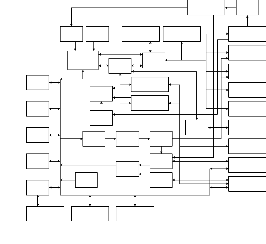
MODEL 2130 MARKER BEACON
Rev. A April, 2005 2-7
This document contains proprietary information and such information may not be disclosed to others for any
purposes without written permission from SELEX Sistemi Integrati Inc.
Microcontroller
with Watchdog,
DMA, and Serial
Port.
Oscillator
Flash ROM
NVRAM
Real Time
Clock with
BBU
Voltage
Supervisor /
Reset
D-A
Converter Active Filter Marker
Beacon Test
Signals
SDRAM
Eight Uarts
TTL / RS232
Converters
J1 Conn (DB37)
BCPS/FFM1/FFM2
J2 Conn (60 Pin Hdr)
LCU
J3 Conn (DB25)
Marker Beacon 1
J4 Conn (DB25)
Marker Beacon 2
J5 Conn (DB9)
RCSU Radio/Cell
Modem
J6 Conn (DB9)
PMDT External
Modem
J7 Conn (USBB)
PMDT USB
J8 Conn (14 Pin Hdr)
Emulator
J9 Conn (10 Pin Hdr)
SPI Boot
Config
Switches
LCU Parallel
Port Bus
Ident
Multiplexor
Amplifier /
Speaker
16-1
Multiplexor
16-1
Multiplexor
A-D
Converter
J10 Conn (50 Pin Hdr)
Test
TB1 (13 Pos Block)
GP I/O1
TB2 (13 Pos Block)
GP I/O2
JP4 Conn (4 Pin Hdr)
PMDT RS232
JP6 Conn (4 Pin Hdr)
Debug RS232
Socketmodem: PMDT
Dial-up
Socketmodem: RCSU
Dedicated
+3.3V, +5V, +/- 15V,
+/- 12VA, +/-12VD
Supplies
VDC Raw
USB / TTL
Converter
Figure 2-2 Marker Beacon RMS CCA Block Diagram
2.3.2.2 Marker Beacon RMS CCA Detailed Circuit Theory
Refer to Figure 11-15. Battery-backed DC power in the range of +10.4VDC to +15VDC enters the RMS CCA on J1-19 and
J1-17 and is diode-OR’D by CR3 and CR4 to create RADIO_V+. RADIO_V+ is directly regulated to +3.3VDC by DC-DC
converter PS1 and can be measured on test point TP7. The voltage level of RADIO_V+ is lowered by CR8, CR9, and CR10
before regulation by DC-DC converter PS3, creating +15V and -15V which can be measured on TP15 and TP16.
The -15V output of PS3 is filtered by C44, L5, and C53 before regulation to -12ANA by U10 and is measurable at TP4. The
-15V is also directly regulated to -12DIG by U13 and is measurable at TP5.
The +15V output of PS3 is filtered by C54, L6, and C56 before regulation to +12ANA by U11 and is measurable at TP6.
The +15V is also directly regulated to +12DIG by U14 and is measurable at TP8. The +12DIG is further regulated to +5DIG
measurable at TP9.
The last power supply for the RMS is 1.2V and can be measured at TP3. The U8 microcontroller generates a pulse-width-
modulated (PWM) signal at U8-4 and U8-5 which drives transistor Q1. Diode CR2, inductor L1, and capacitor C37
complete the DC-DC converter which creates the +1.2VDC used for powering the core of the U8 microcontroller.
The U8 microcontroller accesses its program from U1 and U2 flash ROM. System variables are stored in U3 NVRAM.
Further storage and execution area is available in the U4 SDRAM. Clock Oscillator Y2 generates the heartbeat for the U8
microcontroller as well as the U25 and U20 UARTs. Voltage/reset supervisor U7 monitors +3.3V and resets U8 if +3.3V
drops too low or if an external reset from the LCU enters via J2-31.
MODEL 2130 MARKER BEACON
2-8 Rev. A April, 2005
This document contains proprietary information and such information may not be disclosed to others for any
purposes without written permission from SELEX Sistemi Integrati Inc.
All address and data lines are buffered through drivers U57, U58, U59, U60, and U61 before connecting to any memory-
mapped device except those to the U4 SDRAM, which are directly connected to U8. The drivers reduce the address and
data line capacitance seen by the U8 microcontroller so that the U4 SDRAM may operate at very high speeds.
The CR5 STATUS light emitting diode (LED) provides visual indication of proper operation of the U8 microcontroller and
that RADIO_V+ power is present.
Three grounds are utilized on the RMS CCA. Earth (EGND) ground is the drain path for all transient voltage suppression
(TVS) devices. The E1 lug and several mounting holes provide the route for EGND to leave the board. EGND is
referenced to digital ground (DGND) through inductor L2. DGND is the common point for all high-speed, high current
signals and is referenced to analog ground (AGND) through resistor R35. AGND is the quiet common point for signals
that must be measured accurately or maintain stable levels.
The U15 real-time clock (RTC) keeps time, day, week, and year information and is clocked by oscillator U9. Both U15 and
U9 are battery-backed by battery B1. Battery B1 can be disconnected at header JP3, usually only done for storage or
shipment of the RMS CCA or replacement of B1. The U15 RTC communicates serially to the U8 microcontroller at U15-6
and U15-5.
The U8 microcontroller and U1/U2 flash ROMs can be programmed and debugged in the factory using the J8 emulator
and J9 SPI Boot headers.
The DB37 J1 BCPS connector’s primary function is routing analog signals between the BCPS and
RMS/MKR1/MKR2/LCU CCAs. The Marker1 J3 and Marker2 J4 connectors are both DB25 types while the J2 LCU is a 60
pin shrouded header.
Input buffer U45 is used to read the states of REMOTE/*LOCAL (J2-19), BATT1_FAULT (J1-37), BATT2_FAULT (J1-
36), ON_BATT1 (J1-35), ON_BATT2 (J1-34), and *TEST (J2-44); all of which are pulled up by resistor network RN9.
*TEST when low will cause the lighting of all LEDs on the LCU and BCPS CCAs but does not affect the RMS, FFMX, or
Marker BeaconX LEDs.
Input buffer U44 is used to read the states of SPARE_DIN1 (TB2-2), SPARE_DIN2 (TB2-3), SPARE_DIN3 (TB2-4),
SPARE_DIN4 (TB2-5), DED/*RADIO, DIALUP/*EXT, SMOKE_DETECTOR (TB1-10), and INTRUSION_SENSOR (TB1-
11); all of which are pulled up by resistor network RN8 and resistors R106 and R107. DED/*RADIO and DIALUP/*EXT
are strapped at header JP1 to determine tip/ring versus RS232 modem operation.
Latches U38 and U32, input buffer U42, and RS422 driver U34 comprise the bidirectional parallel port interface PPI
between the RMS and the LCU CCAs. Data transfers occur on the PDATA0 (J2-3) through PDATA7 (J2-10) bus. This
PDATA bus is pulled down through resistors on the LCU CCA. The RMS is considered the master and the LCU is
considered the slave.
Analog multiplexor U52 switches Ident signals FFM1_IDENT (J1-3), FFM2_IDENT (J1-22) MKR1_IDENT (J3-5), and
MKR2_IDENT (J4-5) through to R86, R85, and C134 under control of latch U53. Resistor R86 and R85 divide the Ident
tone to audio input levels before feeding audio amplifier U27 through coupling capacitor C134. Each Ident tone can be
individually switched through the U52 multiplexor as well as DGND; which will not have an audio tone (Ident mute).
FFM TX Disable header JP2 will normally not connect the FFM1 or FFM2 TX to J1-1 or J1-20 to prevent interference with
a direct-connected Far Field Monitor. This option header may be used differently in future designs.
MODEL 2130 MARKER BEACON
Rev. A April, 2005 2-9
This document contains proprietary information and such information may not be disclosed to others for any
purposes without written permission from SELEX Sistemi Integrati Inc.
Quad UART U25 provides four serial ports of the RMS CCA; the local PMDT, the Marker Beacon1, the Marker Beacon2,
and the FFM1 ports. The local PMDT has two possible connection means; either through USB connector J7 or RS232
header JP4. PMDT local select header JP5 must be strapped properly for either of them to operate. If the RS232 option is
selected (normally only at the factory), U36 performs the RS232-TTL level conversions. If the USB option is selected, U63
performs the USB-TTL translations. U63 is clocked by crystal Y3 and serial EEPROM U5 may be used for USB ID storage.
U63 also toggles LEDs CR11 and CR12 to indicate transmission and reception of USB data.
RS232-TTL converter U36 also translates Marker Beacon1 and Debug header JP6 signals. Debug header JP6 is normally
only used at the factory. The debug signals route to the microcontroller at U8-81 and U8-82. RS232-TTL converter U37
translates the Marker Beacon2 and FFM1 signals before routing to/from quad UART U25.
General purpose I/O from TB1 and TB2 are transient protected by CR27 through CR31 and CR36 through CR44. Resistors
R127 through R130 pull down SPARE_ANA1 (TB1-6) through SPARE_ANA4 (TB1-9) before they route to TEST header
J10 (normally used only at the factory) and multiplexor U33. Test header J10 has most of the general purpose I/O as well
as the PMDT and RCSU tip/ring signals.
Exterior temperature is sensed as EXT_TEMP_TVS- (TB1-2), transient protected by CR25, scaled by R102 and R103, and
buffered by U55:A. The formulae needed to convert the output voltage measured at TP26 to temperature are shown near
U55:A. Interior temperature is sensed by U39, scaled by R104 and R105, and buffered by U55:B. The same formulae apply
for interior temperature as exterior temperature.
Quad UART U20 provides four serial ports of the RMS CCA; the remote PMDT, the RCSU, the FFM2, and the spare
Marker BeaconX ports. The remote PMDT has two possible connection means; either through tip/ring modem U24 via
TB2-10 and TB2-11 (Dialup) or RS232 DB9 connector J6 (*External RMM). Modem select header JP1-4 must be strapped
properly for either of them to operate. If the RS232 option is selected (*External RMM, JP1-4 strapped to JP1-6), U41
performs the RS232-TTL level conversions. If the tip/ring modem option is selected (Dialup, JP1-4 strapped to JP1-2), the
U24 socketmodem performs the tip/ring to TTL translations. Socketmodem U24 also toggles LEDs CR13, CR14, CR15,
CR16, and CR17 to indicate ring, transmission, reception, and handshake status of the dial-up modem.
Two options also exist for the RCSU modem; either through tip/ring modem U26 via TB2-12 and TB2-13 (Dedicated) or
RS232 DB9 connector J5 (*Radio). Modem select header JP1-3 must be strapped properly for either of them to operate. If
the RS232 option is selected (*Radio, JP1-3 strapped to JP1-5), U40 performs the RS232-TTL level conversions. If the
tip/ring modem option is selected (Dedicated, JP1-3 strapped to JP1-1), the U26 socketmodem performs the tip/ring to TTL
translations. Socketmodem U26 also toggles LEDs CR18, CR19, CR32, and CR33 to indicate transmission, reception, and
handshake status of the dedicated modem.
In summary, the strapping of modem select header JP1-4 and JP1-3 selects which sets of TTL level signals are directed
to/from quad UART U20 by buffers U22 and U28.
The tip/ring modem signals of the U24 dial-up socketmodem are filtered and transient protected by FL1, FL2, and CR20
before routing to TB2-10 and TB2-11. The tip/ring modem signals of the U26 dedicated socketmodem are isolated from
common-mode noise by transformer T1, then filtered and transient protected by FL3, FL4, and CR34 before routing to
TB2-12 and TB2-13.
U41 performs the RS232-TTL level conversions for the FFM2 port and U40 performs the RS232-TTL level conversions for
the spare Marker BeaconX port. Either spare Marker Beacon1 or spare Marker Beacon2 port is selected depending on the
strapping of Marker Spares header JP8.
Both the dial-up U24 and dedicated U26 socketmodems have audio outputs routed to Audio header JP7. If enabled, the
audios of the socketmodems, as well as Ident audio mentioned previously, are amplified by U27 and presented at speaker
SPK1. Audio header JP7-5 and JP7-6 must be strapped together to enable the amplifier.
MODEL 2130 MARKER BEACON
2-10 Rev. A April, 2005
This document contains proprietary information and such information may not be disclosed to others for any
purposes without written permission from SELEX Sistemi Integrati Inc.
U33 and U16 comprise a 32 to 1 channel analog multiplexor controlled by latch U54 and inverter U17:D. All power supplies
with potentials greater than ±12V are scaled down by resistor networks RN12 and RN13 before presentation to U33.
Voltage reference U30 serves both as a reference check for the U31 A-D converter as well as the base reference for D-A
converter U56.
Buffer amplifier U29 presents the selected analog channel to A-D converter U31. Converter operation is controlled by the
latch U54 A_D_R/*C signal, with a TTL low initiating a conversion. Conversion status and data bus output of the
converter are read through buffers U46 and U47. Resistor networks RN11 and RN10 pull up the converter data bus during
tri-state conversion periods. Buffer inputs U46-3 and U46-4 are reserved to denote any major hardware revisions to the
RMS CCA that might occur in the future.
Operational amplifiers U35:C and U35:D and associated components form a full-wave rectifier/amplifier circuit for the
system AC current sensed on the BCPS CCA and routed on-board from J1-9. Potentiometer R93 will scale the output of
this circuitry to fit the ratios shown near TP23 and R93.
Operational amplifier U35:B buffers the System1 AC voltage sensed on the BCPS CCA and routed on-board from J1-29
after it is scaled by potentiometer R99 and transient protected by CR22. The scaled voltage can be measured at TP24 and
will behave according to the formula shown near this test point and resistor R98.
Operational amplifier U35:A and associated circuitry perform the same function for System2 AC voltage from J1-28 as
U35:B discussed previously.
Instrumentation amplifier U48 amplifies the differential signals Batt1_Curr+ and Curr- sensed on the BCPS CCA and
routed on-board from J1-7 and J1-8. These signals are transient protected by CR45 and CR46. Resistor R108 sets the gain
of the amplifier to that of the ratio shown near U48-6 and the scaled output can be measured at TP19.
Instrumentation amplifiers U49, U50, and U51 and associated circuitry perform the same function for Batt2_Curr+,
Raw1_Curr+, and Raw2_Curr+ from J1-6, J1-5, and J1-4 as U48 discussed previously. Raw1_Curr+ and Raw2_Curr+
represent the DC current sensed for the System1 and System2 power supplies. Batt1_Curr+ and Batt2_Curr+ represent the
charging or discharging currents of the System1 or System2 batteries.
D-A converter U56 creates test waveforms which are sent to both Marker Beacon1 (J3-18, J3-19) and Marker Beacon2 (J4-
18, J4-19) for test purposes. The test waveform from the U56 D-A converter is low-pass filtered by op-amps U6:A and
U6:B. Op-amps U6:C and U6:D, along with resistor network RN14, transform the ground-referenced test waveform to
differential levels before exiting to the Marker Beacons. The ground-referenced test waveform is also fed back to the A-D
converter (U16-10) and can be measured at TP29.
Address decoding is accomplished by decoders U23, U21, and U18. The devices decoded include the U4 SDRAM, the U1
and U2 flash ROMs, the U3 NVRAM, the U25 and U20 UARTS, the U45 and U42 parallel port data (read), the U32 parallel
port data (write), the U38 parallel port control, the U54 and U53 A-D/multiplexor control, the U43 and U44 configuration
switches/digital inputs, and the U46 and U47 A-D converter data bus.
The U8 microcontroller does not have an A0 address line so all external accesses are accomplished in a 16-bit wide (word)
format. The address map for the RMS CCA can be found near decoder U23.
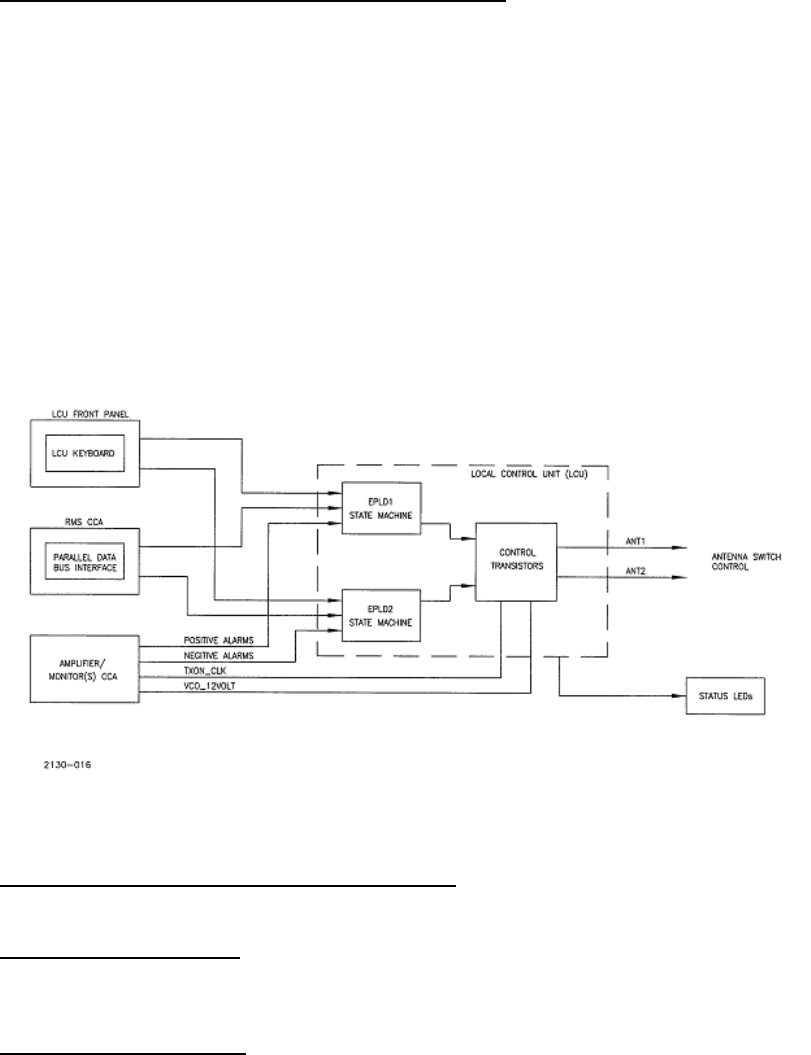
MODEL 2130 MARKER BEACON
Rev. A April, 2005 2-11
This document contains proprietary information and such information may not be disclosed to others for any
purposes without written permission from SELEX Sistemi Integrati Inc.
2.3.3 Local Control Unit (1A1) Simplified Theory of Operation
Refer to Figure 2-3. The Local Control Unit (LCU) controls the normal operation of the Marker Beacon. All operational
functions are performed by the LCU and are controlled by either front panel keyboard when in the local mode or by the
Remote Maintenance Subsystem (RMS) through the parallel interface. The LCU is controlled by the Portable
Maintenance Data Terminal (PMDT), Remote Control Status Unit (RCSU) or Remote Status Unit (RSU) through the RMS
for all remote operator intervention or by the RMS for automatic restart. The LCU receives the alarm outputs from the
installed Amplifier/ Monitor circuit card(s) and depending on the configuration of the system, uses the results of these
signals to determine alarm status. If an alarm is detected, the LCU shuts down the system currently radiating and
transfers to the standby system in accordance with the system configuration. The LCU also provides the ability to
disable monitors and bypass alarms as required by the operator.
The LCU provides +12V to the two possible synthesizer VCO circuits, the +12V to activate the transfer switch, and the
transmit enable clock to the installed Amplifier/ Monitors.
Status is reported by LED's visible to operator standing in front of the Marker, or through the RMS to the
PMDT/RCSU/RSU. An alarm shutdown is reported to the RMS as well as indicated by an audible alarm.
Figure 2-3 LCU Simplified Block Diagram
2.3.3.1 Local Control Unit (1A1) Block Diagram Theory
Refer to Figure 2-3.
2.3.3.1.1 DC to DC Converter
The LCU receives +12V from the two independent system power supplies and diode OR's the two sources to provide
input power to a DC to DC converter which supplies all required voltages for the LCU.
2.3.3.1.2 Power Fail Detectors
Each of the two independent +12V sources is monitored by a voltage comparator to monitor the health and availability of
power from each of the sources. These signals are used to determine voting logic for the alarm registers and are reported
back to the RMS via the parallel interface.
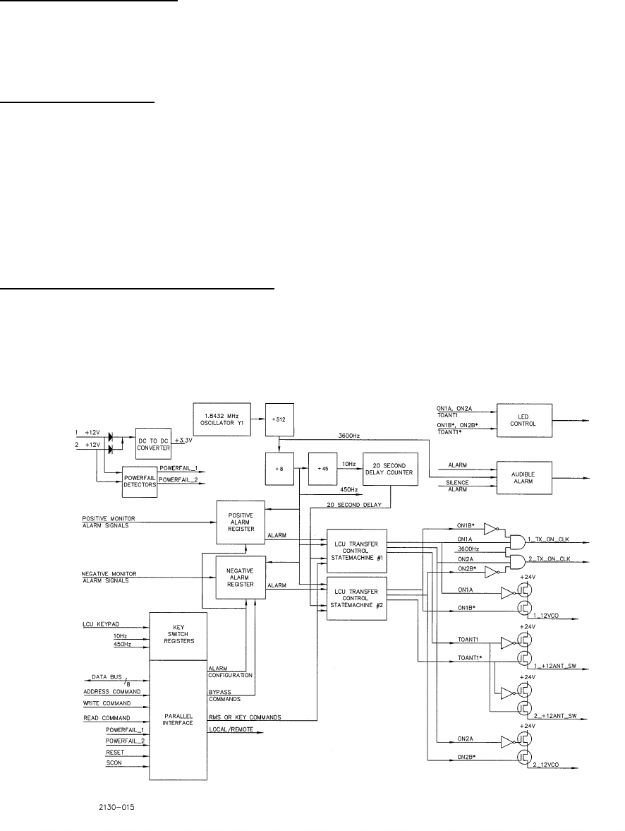
MODEL 2130 MARKER BEACON
2-12 Rev. A April, 2005
This document contains proprietary information and such information may not be disclosed to others for any
purposes without written permission from SELEX Sistemi Integrati Inc.
2.3.3.1.3 Key Switch Registers
Front panel switches are de-bounced and held in the Key Switch Registers pending processing by the LCU transfer state
machines. Commands received from the RMS via the parallel interface also control the contents of the Key Switch
Registers. The registers will hold the last command received until the LCU transfer state machine processes the
command.
2.3.3.1.4 Parallel Interface
The interface to the RMS is via a parallel data bus consisting of eight (8) data bits, an Address Command line, a Write
Command line, and a Read Command line. The sequence to access internal registers within the LCU consist of the
address being placed on the data bus followed by the strobing of the Address Command line to latch the address into the
internal address register. This is followed by the Read Command line driven true to facilitate a read from the latched
address. For a write command, the address is followed by the data to be written to the LCU followed by strobing the
Write Command line.
Alarm Configuration, Bypass Commands, Key Commands, and basic LCU configuration are some of the bits controlled by
the RMS via the parallel interface. State machine Status, Power-fail Status, System Configuration bits (SCON), and
Local/Remote status are some of the status bits that are readable by the RMS via the parallel interface.
2.3.3.1.5 1.8432MHz Oscillator/Divider Chains
Refer to Figure 2-4. The LCU employs a 1.8432MHz crystal oscillator to produce all frequencies required by the design.
The frequency is divided by 512 to produce 3600Hz used to produce the audible alarm tone and the Transmit On clocks
driven back to the monitors. The signal is further divided by 8 to produce 450Hz used as the system clock within the
design. This signal is divided by 45 to produce 10Hz used in the 20 second delay counter and the Key De-bounce
circuits.
Figure 2-4 1.8432 MHz Oscillator/Divider Chains

MODEL 2130 MARKER BEACON
Rev. A April, 2005 2-13
This document contains proprietary information and such information may not be disclosed to others for any
purposes without written permission from SELEX Sistemi Integrati Inc.
2.3.3.1.6 Positive Alarm Register
This register receives the positive (high True) alarms from the two potential monitors within a system. Depending on the
configuration of the alarm voting and bypass logic, the Alarm Register will report an alarm to the transfer state machines if
reported by the enabled monitors.
2.3.3.1.7 Negative Alarm Register
This register receives the negative (low True) alarms from the two potential monitors within a system. Depending on the
configuration of the alarm voting and bypass logic, the Alarm Register will report an alarm to the transfer state machines if
reported by the enabled monitors.
2.3.3.1.8 20 Second Delay Counter
The 20 second delay counter is activated whenever the system initially powers up or a transmitter has been shut down
without transferring to a standby system to ensure that the system will not radiate any signal for a period of 20 seconds
following the shutdown.
2.3.3.1.9 LCU Transfer Control State Machine #1 and #2 and Discrete Controls
The heart of the LCU is the two redundant transfer control state machines. These are configured by the RMS; receive key
commands from the front panel or from the RMS, and process alarms reported by the monitors after being filtered by the
Positive and Negative Alarm Registers. Once configured for on air, the state machines will drive out the required signals
to enable the transmit on clocks (1_TX_ON_CLK, 2_TX_ON_CLK), enable the +12V power to the synthesizer VCO's
(1_12VCO, 2_12VCO), and select the required system to be placed on the antenna (1_+12ANT_SW, 2_+12ANT_SW).
With the redundant state machines, detection of an error assures that the system generating the error will be removed
from the air. The LCU transfers to the standby system if configured to do so either immediately for a Hot Standby system
or after a 20 second delay for a Cold Standby system. If further alarms are detected, the LCU transfer state machines will
shut the standby transmitter down and block any further transmission for a minimum of 20 seconds. Restarts are under
the control of the RMS.
The LCU transfer control state machines report status back to the RMS indicating the state of the state machines, and any
shutdowns that have occurred. The front panel LED's reflect the current state of the state machines.
2.3.3.1.10 LED Control
Status is fed back to a local operator via the LED's on the front panel of the LCU. These reflect the state of the
transmitters and the various alarms as reported by the monitors.
2.3.3.1.11 Audible Alarm
If an alarm as reported by the monitors is detected that is not bypassed, the audible alarm is generated. The audible alarm
can be reset by pressing the Alarm Silence button on the front panel. In local mode, the audible alarm is disabled.
2.3.3.2 Local Control Unit CCA (1A1A1) Detailed Theory of Operation
Refer to Figure 11-14. The LCU controls the sequencing of the main and standby Marker Beacon transmitters according
to alarm signals from the monitors. It displays the status of the station and accepts control input from a local operator.
The LCU also provides status to and accepts control information from the PMDT or RCSU through the RMS parallel
interface. The LCU circuit card consists primarily of two Field Programmable Gate Arrays (FPGA's), discrete control logic
and digital interface circuitry. It also contains light emitting diodes (LEDs).
2.3.3.2.1 Power Supply
The power for the LCU CCA comes from two separate sources of +12 VDC through Schottky rectifiers CR29 and CR30.
The rectifiers isolate the two +12 VDC sources from each other and allow either to supply power to the board. The +12
VDC is converted to +3.3 VDC by a DC to DC converter, PS1. The +3.3 VDC supplies power for all the circuitry in the
LCU.

MODEL 2130 MARKER BEACON
2-14 Rev. A April, 2005
This document contains proprietary information and such information may not be disclosed to others for any
purposes without written permission from SELEX Sistemi Integrati Inc.
Each of the two +12 VDC sources used to power the board are monitored by comparator U10. The two comparator
circuits are identical, so the following discussion will explain the monitoring of the 1_+12 VDC supply. The +12 VDC
supply voltage is reduced to approximately +2.7 VDC by a voltage divider network consisting of R33 and R37. This
voltage is connected to the positive input of comparator U10A. The +3.3 VDC VCC supply is reduced to 2.18 VDC by
another voltage divider network, R30 and R31. This voltage is connected to the negative input of U10A. When the +12
VDC supply is at a normal voltage, the positive input to U10A is higher than the negative input so the output of the
comparator will be at a high logic level. Since the output of the comparator is an open collector, R32 is necessary to pull it
high. When the voltage of the +12 VDC supply falls below approximately +9.60 VDC, the voltage at the positive input of
U10A will fall below +2.18V and cause the output of U12A to go to a low logic level.
2.3.3.2.2 Pushbutton Switches and LED Display
The LCU accepts control input from the operator through momentary contact pushbutton switches and presents status
information for the Marker Beacon station through a series of light emitting diodes (LEDs). The pushbutton switch
circuitry is implemented by using a pull up resistor to +3.3V to produce a high logic level and using a pushbutton switch
to momentarily ground it to produce a low logic level. Switches that provide a toggling or sequencing function (where a
multiple push would give a different result from a single push) are de-bounced by logic within the EPLDs (U1 and U3).
For other switches, a repetitive contact or bounce will not have a noticeable affect.
The board uses three different colors of LEDs: red, yellow, and green. Each of the three colors has a slightly different
forward bias voltage and efficiency. Because of this, two different values of series resistor are used in order to create the
same degree of perceived brightness. A lamp test pushbutton is implemented in the LCU in order to turn on all the LEDs
to confirm their functionality. When the lamp test switch, S3, is pushed, logic within U1 and U3 causes all outputs to
LEDs to be driven low, lighting the LEDs.
2.3.3.2.3 Parallel Interface
The RMS communicates with the LCU and the Cabinet Interface Unit (CI) through an eight bit parallel bus interface. In
order to keep the design of the peripheral (LCU or CI) simple, the RMS controls all the communication on the interface.
The RMS reads and writes to the peripheral circuitry with no handshaking. The interface consists of an eight bit bi-
directional address/data bus, an address strobe, a write strobe, and a read enable. In order to achieve sufficient noise
immunity, the address strobe and the data write strobe are driven differentially through an RS-422 interface IC, U4. The
remainder of the interface is driven to 3.3V CMOS logic levels.
The parallel interface uses the following signals:
Address/Data Bus The eight bit bi-directional address/data buss with multiplexed address.
Address Strobe A differentially driven pulse from the RMS to latch address information
into the peripheral.
Data Write Strobe A differentially driven pulse from the RMS to write data to the peripheral.
Data Read Enable A pulse from the RMS to enable data from the peripheral to be placed on
the data bus.
The RMS has the ability to read the status and control the operation of the Marker Beacon station through a parallel
interface. Data transfer is accomplished by first placing an address on the bus and cycling the address strobe (asserting
and then de-asserting the address strobe signal). The LCU latches and decodes the address within the EPLD's U1 and
U3. For a read operation, the read enable is then asserted which tells the LCU circuitry to place the appropriate data on
the data bus. For a write operation, the RMS places data on the data bus, then cycles the Data Write Strobe (asserting
and de-asserting the write strobe signal.) The address decoding circuitry within the EPLD's decodes eight addresses,
starting at (hexadecimal) 80. To buffer the EPLD's, a bus transceiver U21 is used on the data bus to provide CMOS logic
thresholds to/from the parallel interface.

MODEL 2130 MARKER BEACON
Rev. A April, 2005 2-15
This document contains proprietary information and such information may not be disclosed to others for any
purposes without written permission from SELEX Sistemi Integrati Inc.
Addr = 80 Write Read
Bit 0 Monitor Enable 1 Monitor Enable 1
Bit 1 Monitor Enable 2 Monitor Enable 2
Bit 2 Monitor Enable 3 Monitor Enable 3
Bit 3 Monitor Enable 4 Monitor Enable 4
Bit 4 Monitor Logic (And/Or) Combined Monitor Logic (And/Or)
Bit 5 Maintenance Alert Shutdown/Log Error
Bit 6 Remote Fault Transfer In Process
Bit 7 Hot Standby Standby Shutdown/Enable Restart
Addr = 81 Write Read
Bit 0 Internal Monitor Bypass Internal Monitor Bypass
Bit 1 Standby Monitor Bypass Standby Monitor Bypass
Bit 2 Set Interlocked OFF LED Interlocked OFF LED State
Bit 3 Reserved Reserved
Bit 4 Reserved VCO #1 +12V Sense
Bit 5 Reserved VCO #2 +12V Sense
Bit 6 Main 1 Selected Main 1 Selected
Bit 7 Alarm Silence Alarm
Addr = 82 Write Read
B0 Reserved Integral Monitor Alarm
B1 Reserved Integral Monitor Alarm Mismatch
B2 Reserved Standby Monitor Alarm
B3 Reserved Standby Monitor Alarm Mismatch
B4 Reserved Reserved
B5 Reserved Reserved
B6 Reserved Reserved
B7 Reserved Reserved
Addr = 83 Write Read
Bit 0 Reserved Antenna 1 +12V Switch Sense
Bit 1 Reserved Antenna 2 +12V Switch Sense
Bit 2 Antenna 1 ON 1
Bit 3 Antenna 2 ON 2
Bit 4 Load 1 Power Fail 1
Bit 5 Load 2 Power Fail 2
Bit 6 Off 1 Antenna #1 Selected
Bit 7 Off 2 Local/Remote*
Addr = 84 Write Read
Bit 0 Reserved Reserved
Bit 1 Reserved Reserved
Bit 2 Reserved Reserved
Bit 3 Reserved Reserved
Bit 4 Reserved Reserved
Bit 5 Reserved Reserved
Bit 6 Reserved Reserved

MODEL 2130 MARKER BEACON
2-16 Rev. A April, 2005
This document contains proprietary information and such information may not be disclosed to others for any
purposes without written permission from SELEX Sistemi Integrati Inc.
Bit 7 Reserved Reserved
Addr = 85 Write Read
Bit 0 Reserved Key Bit
Bit 1 Reserved Blink Enable Bit
Bit 2 Reserved Transfer (EPLD2)
Bit 3 Reserved Standby Shutdown/Enable Restart
Bit 4 Reserved Shutdown(EPLD2)/Log Error
Bit 5 Reserved ON 2 (EPLD2)
Bit 6 Reserved ON 1 (EPLD2)
Bit 7 Reserved Antenna Select 1 (EPLD2)
Addr = 86 Write Read
Bit 0 Reserved Combined Monitor Logic (And/Or)
Bit 1 Reserved Transmit Blanking
Bit 2 Reserved Hot Standby
Bit 3 Reserved SCON0
Bit 4 Reserved SCON1
Bit 5 Reserved SCON2
Bit 6 Reserved SCON3
Bit 7 Reserved SCON4
Addr = 87 Write Read
Bit 0 Reserved Combined Monitor Logic (And/Or)
Bit 1 Reserved 0
Bit 2 Reserved Reserved
Bit 3 Reserved Reserved
Bit 4 Reserved 0
Bit 5 Reserved 0
Bit 6 Reserved 0
Bit 7 Reserved 0
Addr = 88 Write Read
Bit 0 Reserved Reserved
Bit 1 Reserved Reserved
Bit 2 Reserved Reserved
Bit 3 Reserved Reserved
Bit 4 Reserved Reserved
Bit 5 Reserved Reserved
Bit 6 Reserved Reserved
Bit 7 SCON5 SCON5
Addr = 89 Write Read
Bit 0 Reserved Reserved
Bit 1 Reserved Reserved
Bit 2 Reserved Reserved
Bit 3 Reserved Reserved
Bit 4 Reserved Reserved

MODEL 2130 MARKER BEACON
Rev. A April, 2005 2-17
This document contains proprietary information and such information may not be disclosed to others for any
purposes without written permission from SELEX Sistemi Integrati Inc.
Addr = 89 Write Read
Bit 5 Reserved Reserved
Bit 6 Reserved Reserved
Bit 7 LOCPRN, LOCCLRN Reserved
2.3.3.2.4 Monitor Alarm Interface Circuitry
In order to insure that a monitor alarm signal is communicated to the control logic, redundancy is incorporated into the
monitor alarm signals. Each alarm signal is sent as two signals, one active high and the other active low. In the LCU,
resistors are used to pull each of their signals to their active (alarm) state. This insures that an alarm condition will be
sensed if there is an open in either alarm line. If an alarm line is shorted to its inactive (non-alarm) state, the other line will
communicate an alarm condition. If the 1_INT_ALARM+ signal is disconnected, a resistor in RN3 will pull the input high
resulting in an alarm condition being sent to the control logic in the EPLD U3. If the 1_INT_ALARM- signal is
disconnected, a resistor in RN15 will pull the input to a low logic level. The output of buffer U17 will send a low level
which will result in an alarm condition being sent to U22. HC logic devices are used to provide CMOS (mid rail)
thresholds for the alarm inputs.
2.3.3.2.5 Station Control Logic
The station control logic is duplicated in both U1 and U3. The logic responds to local operator control through the
pushbutton switch inputs as well as remote control through the parallel interface. The local operator can perform the
following functions:
a. Specify which Marker transmitter is to be designated as main.
b. Turn either transmitter ON and connect it to the antenna.
c. Turn either transmitter ON and connect it to the load.
d. Turn either transmitter OFF.
e. Toggle the bypass state of either of the monitored signal sources (Integral, Standby).
f. Silence the aural alarm (until the next event causes it to sound).
g. Toggle the state of local control. When local control is set, input from the keypad is enabled.
The following functions can be performed by the RMS through the parallel interface:
a. Functions a-g listed above.
b. Enable or disable the alarm signals from either one of the monitors. When a monitor's alarm signals are disabled, it is
functionally equivalent to the monitor producing constant alarms.
c. Set the "AND/OR" state of the alarm logic when it combines the alarm signals from Monitor 1 with the alarm signals
from Monitor 2. When set to "AND", both monitors must provide an alarm from the same source to cause the station
to transfer. When set to "OR", Monitor 1 signaling an alarm or Monitor 2 signaling an alarm will cause the station to
transfer.
d. Set the "Maintenance Alert" state. This lights the corresponding LED on the panel and sounds the aural alarm.
e. Set the "Remote Control Fault" state. This lights the corresponding LED on the panel and sounds the aural alarm.
In the alarm logic circuitry, the alarms from Monitor 1 alarm status are displayed on the panel. Similarly, the alarms from
Monitor 2 alarm status are displayed on the panel. If a given monitor’s alarm signals are disabled by the RMS, it is
equivalent to all of that monitor's alarm signals being asserted. The state of the AND/OR setting determines whether both
or either of the Monitor 1 or Monitor 2 signals are required to produce a transfer condition. If one of the two +12V power
fail logic signals from U10 goes active, the alarm logic will force an alarm condition for the monitor pair that is powered
from the corresponding +12V supply. In order to avoid shutting the Marker Beacon station down, the alarm logic is
forced to the AND state. This allows the other monitor to monitor the system.

MODEL 2130 MARKER BEACON
2-18 Rev. A April, 2005
This document contains proprietary information and such information may not be disclosed to others for any
purposes without written permission from SELEX Sistemi Integrati Inc.
The alarm signals from the monitors have already been given the appropriate transfer delay times within the monitors.
This results in an immediate transfer when the combinatorial requirements of the alarm signals are met. When a transfer
condition occurs, the present transmitter that is connected to the antenna system is taken off the air. The other
transmitter is connected to the antenna system, and turned on (if it is not already on). If the transmitter, not designated as
main connected to the antenna system when the transfer condition occurs, the control logic will enter the shutdown state
and both transmitters are turned off. Once the control logic enters the shutdown state, no further transfer operations will
take
place until a local operator or the RMS turns one of the transmitters on and specifies that it is connected to the antenna
system. The Station Control Logic controls which transmitter is connected to the antenna system by the status of the
+12V ANT outputs. In order to insure the state of the antenna transfer relay, a status signal is returned from it. This
signal is monitored by the RMS through the parallel interface at Bits 0 and 1 of address 83 (hex).
2.3.3.2.6 Aural Alarm
An aural alarm is turned on when the system control logic senses an alarm condition as reported by the monitors. The
frequency for the alarm is obtained from U3. It is the 1.832 MHZ divided by 512 which is 3600 Hz. The signal is also
inverted by U3. The inverted and non-inverted 3600 Hz signals are both gated by U3. The two outputs of U3 provide a
differential signal to drive piezoelectric alarm element LS1. The system control logic turns the alarm on by asserting the
active low ~ALARM signal. When the ~ALARM signal is at an inactive or high logic level, the outputs of both U3 will
be high which will result in no differential signal to drive the alarm. The level of the signal is adjusted by R43. R44
prevents the adjustment of R43 to result in a level which is too low.
2.3.3.2.7 System Configuration Inputs
In order to reduce the amount of effort required to program various modules within the Marker for the proper
configuration, there are eight logic signals that are sent from the RMS to each module to specify the system
configuration. The configuration signals are readable by the RMS via hex address 86.
The logic signals are produced by switches on the RMS. Isolation is provided in the event power is lost to the LCU. The
resistors in RN9 pull the inputs to U1 to a high logic level if the configuration inputs are high.
2.3.3.2.8 Clock Oscillator and Divider
Clock signals are necessary for the operation of the sequential circuitry within the two EPLDs U1 and U3. The output of a
1.8432 MHZ oscillator Y1 is sent to U3. U3 divides the oscillator frequency by 16384 to produce a 450 Hz clock signal.
Within U3, the 450 Hz clock is divided by 45 to produce another 10 Hz clock. The 450 Hz clock and the 10 Hz clock are
both used by U1 and U3. The divide by 512 output of U3 is used to provide 3600 Hz for the aural alarm for the LCU.
2.3.3.2.9 Reset and Watchdog Circuitry
A reset circuit U9 is used to provide a reset signal to the LCU logic circuitry when it is powered up or in the event that the
3.3V power supply voltage falls below a threshold. The LCU control logic uses the reset to set the system control logic to
a safe operational state. The alarm bypasses are turned off, the main transmitter is set to #1 and other settings within the
logic are set to a default state. As long as the reset is asserted the transmitter off signals are asserted. When the reset
returns to its non-asserted state, the LCU waits to be configured before any transmitter is turned on and is connected to
the antenna. Immediately after reset, the RMS must update the control settings within the LCU since the default settings
such as monitor enables, Hot Standby and the And/Or selection may not be desired. A pushbutton switch S14 allows the
operator to manually reset the system through the LCU. R34 pulls the MR (pin 1) input to its inactive high state. When
S14 is pushed, the Master Reset signal is asserted low causing U9 to generate a reset within the LCU at the same time the
rest of the system is driven into a reset condition.
A watchdog circuit within U9 monitors the internal 10 Hz clock and de-asserts the transmitter enable signals in the event
that the clock oscillator or the clock dividing circuitry fails. The 10 Hz clock signal is connected to the WDI input of U9.
If the clock fails to toggle for 1.6 seconds, the ~WDO output will go active. Logic within EPLD's U1 and U3 will then
assert the ~OFF1 and ~OFF2 signals to the monitor which will then turn off both Marker Beacon transmitters.
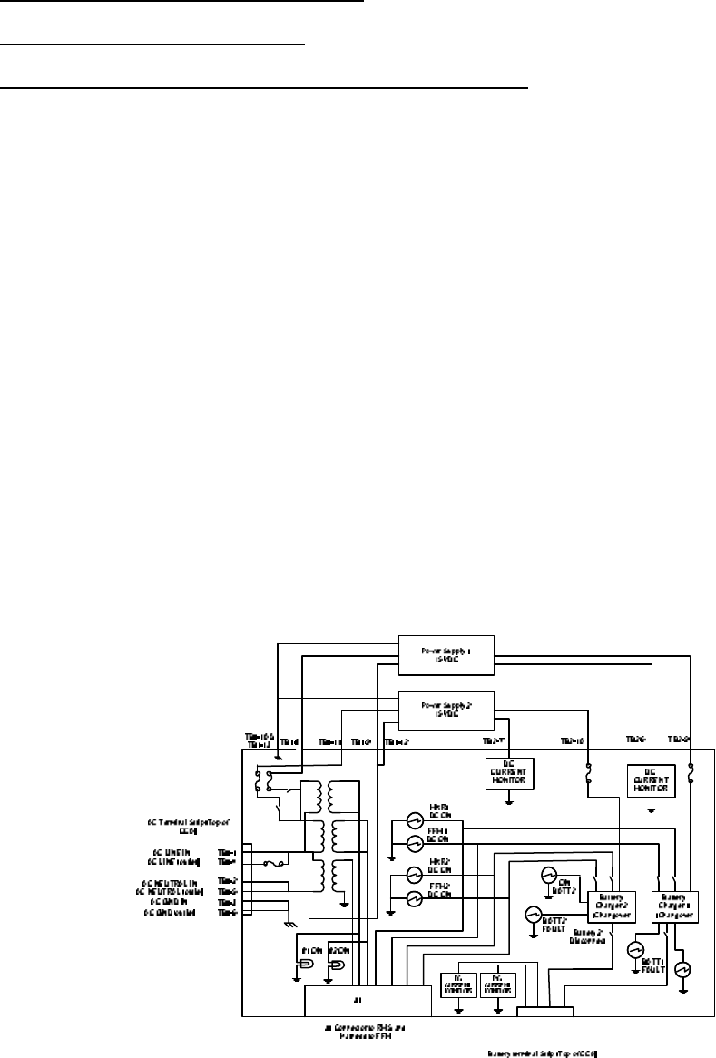
MODEL 2130 MARKER BEACON
Rev. A April, 2005 2-19
This document contains proprietary information and such information may not be disclosed to others for any
purposes without written permission from SELEX Sistemi Integrati Inc.
2.3.4 Power Panel Assembly Theory of Operation
2.3.4.1Power Supply Theory of Operation
2.3.4.2 Battery Charging Power Supply (BCPS) Block Diagram Theory
Refer to Figure 2-5. The Battery Charge Power Supply (BCPS) CCA distributes power, performs battery charging, and
facilitates power monitoring in a single or dual Far Field Monitor (FFM) or Marker Beacon system.
The BCPS CCA receives AC line power at terminal block TB1 and immediately routes it to a fused AC outlet via the same
terminal block. AC current up for to two FFM / Marker Beacon pairs is measured via a single transformer while AC
Voltage for up to two FFM / Marker Beacon pairs is measured by two separate transformers. The secondary of each AC
Voltage sensing transformer shall light an AC_On indicator if AC is detected. The AC voltage secondary and the AC
current secondary are routed to the J1 connector for measuring by the Remote Monitoring System (RMS).
The FFM / Marker Beacon pairs are designated as System1 and System2 and are identical in operation. System1 consists
of FFM1 and Marker Beacon1 while System2 is the FFM2 /Marker Beacon2 pair. Only System1 shall be discussed further.
System1 AC power is fused, switched, and routed via terminal block TB1 to an external AC-DC power supply. The power
supply furnishes +15 VDC back to the BCPS CCA via terminal block TB2. The +15VDC is current monitored, fused, and
routed to Battery1 Charger / Changeover circuitry. A +12 VDC battery for System1 joins the Charger / Changeover
circuitry via terminal block TB2. The Charger / Changeover circuitry monitors the battery voltage/current and switches to
battery back-up power if AC power is no longer present. The Charger / Changeover circuitry also shuts off battery
backup if the battery is near depletion to prevent permanent damage to the battery.
A Battery1 disconnect switch is used for system power-down as well as battery fault testing. Battery1 indicators include
both Batt1_Fault (the battery is not connected or an open cell condition) and On_Batt1 (AC power is no longer present).
The output of the Battery1 Charger / Changeover circuitry is routed to two switches, one each for FFM1 and Marker
Beacon1. An indicator for each DC output is lit if the corresponding switch is activated and DC power for each is routed
to terminal block TB2.
Figure 2-5 FFM / Marker Beacon BCPS Block Diagram

MODEL 2130 MARKER BEACON
2-20 Rev. A April, 2005
This document contains proprietary information and such information may not be disclosed to others for any
purposes without written permission from SELEX Sistemi Integrati Inc.
2.3.4.3 Marker Beacon BCPS CCA Detailed Circuit Theory
Refer to Figure 11-13. AC line, neutral, and earth enter via TB1-1, 2, and 3. The AC line is fused by F5 and routed to the
external AC outlet on TB1-4. The AC neutral for the outlet is routed directly to TB1-5. AC earth for the outlet and both
external power supplies PS1 and PS2 are connected directly to TB1-6, 10, and 13.
Transformer T1 scales AC current detected for both System1 and System2 to its secondary where it is loaded by burden
resistor R3 and transient protected by CR15 before routing to DB25 connector J1.
The FFM / Marker Beacon pairs are designated as System1 and System2 and are identical in operation. System1 consists
of FFM1 and Marker Beacon1 while System2 is the FFM2 /Marker Beacon2 pair. Only System1 shall be discussed further.
The AC line after the transformer T1 primary is fused by F1 and switched by one side of DPDT switch S1. The output of
S1 connects to the primary of voltage-sensing transformer T2, whose secondary scales the voltage before full-wave
rectification by diodes CR3-6. This rectified voltage is transient protected by diode CR1 and filtered by capacitors C1 / C3
before routing to both connector J1 and diode CR54. Diode CR54 performs a diode-OR with the TESTAC1 voltage (more
information later) before entering current-limiter U1. Current-limiter U1 and resistor R1 insure consistent brightness of LED
CR13 regardless of AC voltage or TESTAC1 voltage levels.
The AC neutral, after transformer T2 primary, is switched by the remaining side of the DPDT switch S1 before routing to
TB1-9. An external AC-DC power supply connects to TB1-8, 9, and 10. The external AC-DC power supply converts AC
voltage to +15VDC and connects back to TB2-9 and 6. The positive side of this DC supply (TB2-9 and labeled +15VIN1) is
fused by F3 and routed to the Battery1 Charger / Changeover circuitry (more information later). The negative side of this
DC supply (TB2-6) is routed through current-monitoring resistor R6. The Kelvin-type output connections of resistor R6
are transient-protected by CR19 before routing to connector J1.
Battery1 connects to TB2-1 and 4 where it is reverse-voltage protected by diode CR12. The positive side of this +12 VDC
battery (TB2-1 and labeled BATT1+) is switched by Batt1 Disconnect switch S3 before routing to the Battery1 Charger /
Changeover circuitry (more information later). The negative side (TB2-4) flows through current-sensing resistor R4. The
Kelvin-type output connections of resistor R4 are transient-protected by CR17 before routing to connector J1.
Oscillator circuitry U8:A, C14, and R24 establish an 8192 Hz heartbeat for the battery fault testing of both Battery1 and
Battery2. Inverters U8:C and U8:B buffer and invert the clock signals so that counter U7 and flip/flop U6:A change on the
same edge. Counter U7 sets an overall time period of two seconds while AND gate U9 / U8:D presents a logic high to the
U6:A-5 input for 32 milliseconds of the 2 second time period. The logic high is clocked through U6:A to both the gate of
transistor Q4, shutting down charger U3, and to the gate of transistor Q11, placing a load of R30 and R31 on Battery1. If a
battery is not connected, the load will cause a logic low to be clocked through R81 / U6:B-9, turning on transistor Q5 and
Batt1_Fault indicator CR27.
In summary, once every 2 seconds for 32 milliseconds, a load is placed on the battery to check for its presence.
Charger U3 is a constant voltage / constant current integrated circuit whose final battery voltage is set by resistors R10,
R11, R12, and R13. Charger U3 switches the +15VIN1 through transistors Q1:A, Q2, Q3, diode CR11, inductor L2, and
resistor R8 to Battery1 in a switch-mode manner. Inductor L2 and resistor R8 establish the charger current through
feedback resistors R16 and R17. The switch-mode frequency of charger U3 is set by resistor R18 and capacitor C11. More
information on the charger U3 integrated circuit is available at the manufacturer’s web site.
Charger U3 also routes +15VIN1 through transistors Q1:A and Q1:B to VSUM1 while +15VIN1 is present. If +15VIN1 is no
longer present, Battery1 is switched though transistors Q10:A and Q10:B to this same point labeled VSUM1. VSUM1 is
filtered by capacitors C32, C34, C42, and inductor L4 before routing to switches S5 and S6. If switches S5 and S6 are
closed, VSUM1 is routed to connector J1-11 and 13 and lights MRKR1_DC and FFM1_DC indicators CR21 and CR22.
+15VIN1 also routes to voltage divider R44 and R45 which sets the “on battery” trip point of comparator U5:B, U5:C, and
MODEL 2130 MARKER BEACON
Rev. A April, 2005 2-21
This document contains proprietary information and such information may not be disclosed to others for any
purposes without written permission from SELEX Sistemi Integrati Inc.
U5:D. As long as the +15VIN1 level is above the trip point set by the voltage divider and the +3.3VREF from regulator U4,
the OR’d output of U5:B, U5:C, and U5:D will be pulled high through R83. This high output will simultaneously keep
On_Batt1 indicator CR29 off and transistor Q13 on. Transistor Q13 being on pulls the output of comparator U5:A low
through diode CR80, which in turn keeps battery switch transistors Q12, Q10:A, and Q10:B off.
In summary, if +15VIN1 remains above the “on battery” trip point, the On_Batt1 indicator and battery switch transistors
Q10:A and Q10:B are all off.
If +15VIN1 drops below the “on battery” trip point, the On_Batt1 indicator CR29 is lighted with current regulated by
resistor R47 and zener diode CR85. Transistors Q10:A and Q10:B will then be turned on (switching Batt1 into VSUM1)
until the Batt1 voltage drops below the “battery too low” trip point established by voltage divider R28 / R27 and
+3.3VREF on the inputs of comparator U5:A. Once Batt1 voltage falls below the “battery too low” trip point, the output of
comparator U5:A will go low and shut off transistors Q10:A and Q10:B; thus removing all power to the FFM1 and Marker
Beacon1. This is done to prevent complete discharge of a battery, which might cause permanent damage.
Regulator IC U4 creates +5VREF from the diode OR’d supply VALWAYS which is a combination of +15VIN1, +15VIN2,
Batt1, and Batt2 through diodes CR56, CR57, CR67, and CR68. As long as power is supplied in some way to the board,
VALWAYS and +5VREF exist. Another diode OR’d supply named VSUM1N2 is created by diodes CR25 and CR26 to
power the oscillator and reset circuitry of U6, U7, U8, and U10. As long as VSUM1 or VSUM2 are active, the battery fault
testing will continue.
Charging of Battery1 can be manually disabled by connecting jumper strap JP1A between JP1-1 and JP1-2. Disabling
BCPS1 in this manner shuts off charger U3 and prevents the lighting of on-board Batt1_Fault indicator CR27 and
On_Batt1 indicator CR29 through diodes CR44 and CR45 as well as off-board indicators On_Batt1 J1-1 and Batt1_Fault
J1-3 through diodes CR81 and CR46. Disabling BCPS1 will not allow lighting of On_Batt1 indicator CR29 and Batt1_Fault
indicator CR27 even during a lamp test (TEST* active low).
The TEST* signal from connector J1-14 is the means by which an external controller may light all indicators and stop
battery fault testing. TEST* is filtered by FL3 and transient protected by diode CR42. TEST* connects to the cathode side
of diodes CR51, CR52, CR53, and CR23. When TEST* is low, the On_Batt1 indicator CR29 is lit through CR51 assuming
the BCPS1 disable jumper at JP1 is not in place. Also, reset inverter U8:F is pulled low through diode CR52 causing U6:B
to turn on transistor Q5 and Batt1_Fault indicator CR27 (again assuming the BCPS1 disable jumper at JP1 is not in place).
While Test* is low, transistor Q21 will be turned on; lighting FFM2_DC indicator CR33 through diode CR62, lighting
MKR2_DC indicator CR32 through diode CR63, lighting FFM1_DC indicator CR22 through diode CR64, lighting
MKR1_DC indicator CR21 through diode CR65, lighting SYS1_AC indicator CR13 through diode CR66, and lighting
SYS2_AC indicator CR14 through diode CR24. Finally, current through diode CR90 will light Batt1_Fault indicator CR27
and On_Batt1 indicator CR29 in the event BCPS1 is not powered (again assuming the BCPS1 disable jumper at JP1 is not
in place).
Signal SHDN1* is the means by which an external controller may stop charging of the battery. SHDN1* enters via
connector J1-5, is filtered by inductor FL1 / capacitor C40, transient protected by diode CR41, and connects to charger U3.
A low level on the SHDN1* signal disables charger U3.
MODEL 2130 MARKER BEACON
Rev. A April, 2005 2-1
This document contains proprietary information and such information may not be disclosed to others for any
purposes without written permission from SELEX Sistemi Integrati Inc.

MODEL 2130 MARKER BEACON
Rev. A April, 2005 3-1
This document contains proprietary information and such information may not be disclosed to others for any
purposes without written permission from SELEX Sistemi Integrati Inc.
3. STANDARDS AND TOLERANCES
3.1 Introduction
This section contains a list of equipment parameters, their standards, their tolerances, and references to associated
maintenance paragraphs and computer screen displays. Signal levels, signal bandpass and alarm threshold
requirements at inputs of the RSCS are defined.
3.2 Standards and Tolerances
See Table 4-1 for standards and tolerances using external test equipment for calibration.
Table 3-1 Standards and Tolerances
Tolerance/Limit
Parameter Procedure
Reference Standard Initial Operating
RF Carrier Power Level 5.2.3
As established
by flight
inspection
98 to 102 % of
standard
90 to 110 % of
standard
Modulation Level 5.2.4 95 % 93 to 97 % 91 to 99 %
1) Frequency 5.3.1
a. Carrier 5.3.1
(1) Conventional 75.000 MHz ± 2250 Hz of
Standard
± 3750 Hz of
Standard
(2) Offset Frequency
Operation
75.004 MHz and
74.996 MHz
±1500 Hz of Standard
Same as initial
b. Modulation Tones
(1) Outer marker 400 Hz 399 to 401 Hz 396 to 404 Hz
(2) Middle marker 1300 Hz 1297 to 1303 Hz 1287 to 1313 Hz
(3) Inner marker 3000 Hz 2992 to 3008 Hz 2970 to 3030 Hz
2) Antenna Systems
a. Reflected power level
(VSWR) 5.2.8 1.0:1 = 1.05:1 = 1.1:1
b. Insulation resistance 5.4.4 Infinity = 50 megohms = 20 megohms
c. DC Resistance 5.4.5 Baseline
Measurement
= Standard + 5O
3) Monitor Alarm Points 5.3.6
a. Carrier Power 60 % of normal = 50 % of normal Same as initial
b. Modulation
1. Low Modulation 85% = 80 % Same as initial
2. High Modulation 99% = 99% Same as initial
4)VSWR 5.2.8 2.5:1 = 3.0:1 Same as initial
Automatic Transfer and/or
Shutdown 5.2.6 15 seconds = 30 seconds = 30 seconds
5)Verification of Built-In Test
Equipment (BITE)
a. Power Measurement Error 5.3.2 0.0% = 5.0 % Same as initial
b. VSWR Measurement Error 5.3.4 2.0:1 1.8 to 2.2:1 Same as initial
c. Modulation Percent
Measurement Error 5.3.3 0.0% = 3.0 % Same as initial
MODEL 2130 MARKER BEACON
3-2 Rev. A April, 2005
This document contains proprietary information and such information may not be disclosed to others for any
purposes without written permission from SELEX Sistemi Integrati Inc.
THIS SHEET INTENTIONALLY BLANK

MODEL 2130 MARKER BEACON
Rev. A April, 2005 4-1
This document contains proprietary information and such information may not be disclosed to others for any
purposes without written permission from SELEX Sistemi Integrati Inc.
4. PERIODIC MAINTENANCE
4.1 Introduction
This section contains performance checks and other preventive maintenance that must be performed on a recurring basis,
periodically or at irregular intervals.
4.2 Performance Checks
Table 5-1 is a list of performance checks, including references to applicable standards and tolerances of Section 4 and
maintenance procedure paragraphs of Section 5.
Table 4-1 Performance Checks
Reference Paragraph or Table
Standards and Maintenance
Performance Check Tolerances Procedures
Semiannually
a. Check RF power Table 3-1 5.2.3
b. Check Modulation Table 3-1 5.2.4
c. Check Monitor alarm points Table 3-1 5.3.6
d. Check Antenna VSWR Table 3-1 5.2.8
d. Check automatic transfer/shutdown Table 3-1 5.2.6
e. Check alternate equipment n/a 5.2.7
Annually
a. Measure Frequencies Table 3-1 5.3.1
Built-In Test Equipment (BITE)
Annually
a. Power Output Table 3-1 5.3.2
b. VSWR Measurement Table 3-1 5.3.4
c. Modulation Percentage Table 3-1 5.3.3
As required
a. Initial Installation Table 3-1 5.3.2, 5.3.3, 5.3.4
b. Replacement of BITE Module (1Axx or 1Ayy) Table 3-1 5.3.2,6.3.3,5.3.4

MODEL 2130 MARKER BEACON
4-2 Rev. A April, 2005
This document contains proprietary information and such information may not be disclosed to others for any
purposes without written permission from SELEX Sistemi Integrati Inc.
4.3 Other Onsite Maintenance
Table 5-2 is a list of onsite maintenance tasks, other than performance checks, that are necessary to prevent deterioration
of the equipment and ensure its reliable operation.
Table 4-2 Other Onsite Maintenance Checks
Reference Paragraph or Table
Standards and Maintenance
Maintenance Check Tolerances Procedures
Monthly
Perform Equipment time update n/a 5.2.2
Quarterly
a. Check all warning signs n/a 5.4.1
b. Check Vegetation control n/a 5.4.1
Semiannually
a. Check shelter air filters (if installed) n/a 5.4.1
b. Perform equipment time update. n/a 5.2.2
Annually
a. Clean/ Inspect all equipment n/a 5.4.1
b. Perform backup power (battery) check n/a 5.4.2
c. Measure VSWR at transmitter Table 3-1 5.3.4
d. Inspect RF cables n/a 5.4.3
As Required
a. Measure VSWR at antenna feedlines Table 3-1 5.3.7
b. Measure RF cable insulation resistance Table 3-1 5.4.4
c. Measure RF cable dc resistance Table 3-1 5.4.5

MODEL 2130 MARKER BEACON
Rev. A April, 2005 5-1
This document contains proprietary information and such information may not be disclosed to others for any
purposes without written permission from SELEX Sistemi Integrati Inc.
5. MAINTENANCE PROCEDURES
5.1 Introduction
This section provides the procedures required for accomplishing periodic and incidental maintenance activities. This
section is divided into three parts: performance check procedures, other maintenance procedures, and special
maintenance procedures.
5.2 Performance Check Procedures
Performance checks are accomplished using the built-in test equipment capabilities of the Marker Beacon. These
procedures do not require the use of external test equipment. The procedures can be performed at the Marker Beacon site
or from a physically separated site through the use of the Remote Maintenance Monitoring (RMM) capabilities.
5.2.1 Equipment Sign-On
Sign-on and procedures for operation of the equipment are available in Section Error! Reference source not found..
5.2.2 Perform Time Update
This procedure updates the Marker Beacon time indication.
Note: The RCSU will update time and date on a periodic basis. If the Marker Beacon is connected to an RCSU this time
and date will be replaced with the RCSU time and date. It is suggested that time and date be set at the RCSU so that all ILS
equipment is updated consistently from the RCSU.
5.2.2.1 Test Equipment Required
a. PMDT
b. Accurate time source
5.2.2.2 Procedure
a. Set the Windows Time and date to the value obtained from the accurate time source.
b. Log onto the Marker Beacon with the PMDT.
c. Select RMS>>Commands>>Set time and date. The time and date is now set to match the laptop computer.
5.2.3 Measurement of RF Power
This procedure provides a method to measure the RF power output of the marker transmitter.
5.2.3.1 Test equipment required
PMDT
5.2.3.2 Procedure
a. Log onto the Marker Beacon with the PMDT.
b. Measure the RF carrier power by reading the Transmitter>>Data>> Power Sensor Data.
c. If the carrier power is not within the reference value established during flight inspection, take appropriate action.
5.2.4 Measurement of Modulation Level
This procedure provides a method to measure the Modulation Level of the marker transmitter.
5.2.4.1 Test equipment required
PMDT

MODEL 2130 MARKER BEACON
5-2 Rev. A April, 2005
This document contains proprietary information and such information may not be disclosed to others for any
purposes without written permission from SELEX Sistemi Integrati Inc.
5.2.4.2 Procedure
a. Log onto the Marker Beacon with the PMDT.
b. Measure the Modulation level by reading the Monitor>>Data>>Integral
c. If the Modulation Level is not within the tolerance in Table 3-1, take appropriate action.
5.2.5 Measurement of Modulation Frequency
This procedure provides a method to measure the Modulation frequency of the marker transmitter.
5.2.5.1 Test equipment required
PMDT
5.2.5.2 Procedure
a. Log onto the Marker Beacon with the PMDT.
b. Measure the Modulation frequency by reading the Monitor>>Data>>Integral
c. If the Modulation Frequency is not within the tolerance in Table 3-1, take appropriate action.
5.2.6 Check Automatic transfer/shutdown
5.2.6.1 Test equipment required
Stop watch or suitable timing device.
PMDT
5.2.6.2 Procedure
Note: This test will take the facility offline, issue a NOTAM.
a. With the Marker Beacon in Normal condition, remove the monitor return cable.
b. Measure the time from cable removal to shutdown (single equipment) or transfer (dual equipment).
c. Verify that the measured time is within the tolerance for Table 3-1.
d. For Dual equipment measure the time to shut down for the standby transmitter.
e. Verify that the measured time is within the tolerance for Table 3-1.
f. Restore the Marker Beacon to Normal.
5.2.7 Check Alternate equipment
5.2.7.1 Test equipment required
None

MODEL 2130 MARKER BEACON
Rev. A April, 2005 5-3
This document contains proprietary information and such information may not be disclosed to others for any
purposes without written permission from SELEX Sistemi Integrati Inc.
5.2.7.2 Procedure
Note: This test will take the facility offline, issue a NOTAM.
a. With the Marker Beacon in Normal condition, log off PMDT, and place LCU in remote mode.
b. Remove the monitor return cable.
c. Verify shutdown of the Main transmitter and transfer to the Standby transmitter.
d. Restore the Monitor return cable connection.
e. Verify that the LCU indicates that the Main is OFF and the Standby is ON antenna and aural alarm.
f. Silence the alarm.
g. Verify Remote Control Indications are correct.
h. Restore the Marker Beacon to Normal.
5.2.8 Measure Antenna VSWR at Transmitter Output
5.2.8.1Test Equipment Required
PMDT
5.2.8.2 Procedure
a. Connect the PMDT serial communications cable to the Marker Beacon and Log On.
b. Enter Transmitter>>Data>>Power Sensor Data and view the VSWR reading.
c. Compare the reading to Table 3-1.
d. Log off the PMDT.
5.3 Other Maintenance Procedures
Performing the following procedures will require the equipment to be removed from service. These procedures will also
incorporate steps to calibrate the RMM to external test equipment.
5.3.1 RF Carrier Frequency Measurement
This procedure insures the transmitter output frequencies are within the tolerances of Table 3-1.
NOTE
The following procedure causes a non-useable signal in space by removing the
navigation tone modulation, and requires the proper authorities to be notified of
removal from service for the duration of this check.
5.3.1.1 Test Equipment Required
Bird Wattmeter body
Bird Sniffer element

MODEL 2130 MARKER BEACON
5-4 Rev. A April, 2005
This document contains proprietary information and such information may not be disclosed to others for any
purposes without written permission from SELEX Sistemi Integrati Inc.
5.3.1.2 Procedure
a. Enter Level 3 User ID and password.
b. Push the Local switch on the LCU. Verify that the Local LED is lit.
c. Push the Integral and Standby Bypass switches. Verify that the Bypass LEDs are lit for all valid monitors.
d. Insert RF sniffer in Course CSB wattmeter body.
e. Using a test cable, connect frequency counter to RF sniffer.
f. Turn Off the modulation.
g. Read the frequency on the counter.
h. Record the frequency and confirm that the value is within the tolerance of Table 3-1.
i. Return the Marker Beacon to normal operation.
5.3.2 RF Output Power BITE Calibration
5.3.2.1 Test Equipment Required
Bird Wattmeter body
Bird Sniffer element
5.3.2.2 Procedure
a. Remove primary power.
b. Insert wattmeter with 5W, 50 to 125-MHz element and dummy load into RF output transmission line.
c. Turn on Marker Beacon. After Marker Beacon initializes to the normal state, type in the system password.
d. Place equipment in bypass mode.
e. Adjust wattmeter element to read forward power.
f. Read Forward RF Power in Transmitters>>Data>>Power Sensor Data.
g. Adjust Transmitter>> Configuration >> Power Sensors Offset and Scale factors for the power level measured.
h. Return system to normal operation.
5.3.3 Modulation Percentage BITE Calibration
5.3.3.1 Test Equipment Required
Bird Wattmeter thruline body
Bird Sniffer element
5.3.3.2 Procedure
a. Disconnect primary power.
b. Insert wattmeter with sniffer element and dummy load into RF output transmission line.
c. Connect sniffer element to oscilloscope.
d. Turn on Marker Beacon. After Marker Beacon initializes to the normal state, type in the system password.
e. Put Marker Beacon in bypass mode, then turn keying signal to continuous tone.
f. Observe RF envelope maximum and minimum on oscilloscope.
g. Calculate modulation percentage using the following formula:
100%×
+
−
=VmVp
VmVp
Modulation
where Vp = Peak voltage

MODEL 2130 MARKER BEACON
Rev. A April, 2005 5-5
This document contains proprietary information and such information may not be disclosed to others for any
purposes without written permission from SELEX Sistemi Integrati Inc.
Vm = Minimum voltage
h. Read current modulation percentage on Monitors>> Data>>Integral screen. Compare to the calculated reading. If
they do not agree adjust Monitors>> Configuration >> Offsets and Scale factors to correct.
i. Shut down the Marker Beacon, disconnect all external test equipment, and reconnect all cables.
j. Return Marker Beacon to normal operation.
5.3.4 Forward Power, Reflected Power and VSWR BITE Check
5.3.4.1 Test equipment required
a. Facility built in wattmeter
b. Bird Wattmeter Thuline body with 5 Watt, 50-125 MHz, 1 Watt or less, 50-125 MHz or alternately an HP 437B power
meter or equivalent.
c. PMDT
5.3.4.2 Procedure
a. Remove system power and insert wattmeter with 5W, 50-125 MHz element into RF output transmission line.
b. Place a Tee and two 50 ohm loads on the output cable to the antenna.
c. Turn on Marker Beacon. After Marker Beacon initializes to the normal state, type in the system password.
d. Place equipment in bypass mode.
e. Adjust wattmeter element to read forward power. Note wattmeter indication. Compare with indication of internal test
equipment in Transmitters>>Data>>Power Sensor Data. Compute the error in the Forward Power Bite reading
using:
IndicationPowerentTestEquipm
IndicationPowerBITEIndicationPowerTestEq
Error __
___._
−
=
f. Verify that the error is not within the tolerance of Table 3-1 perform 5.3.5.
g. Insert wattmeter with 1W or less, 50-125 MHz element into RF output transmission line.
h. Set wattmeter element to read reflected power. Note wattmeter indication. Compare with indication of internal test
equipment in Transmitters>>Data>>Power Sensor Data Reflected Power.
IndicationPowerentTestEquipm
IndicationPowerBITEIndicationPowerTestEq
Error __
___._
−
=
i. If the difference is not within the tolerance for Table 3-1 perform 5.3.5
j. Calculate the VSWR using the following formula:
VSWR FWD REV
FWD REV
=+
−
Where FWD = Forward Power and REV = Reverse Power.
k. Compare with internal test equipment indication. Calculated VSWR and screen indication must agree within the
tolerance of Table 3-1 if not, perform 5.3.5.
l. Shut down the Marker Beacon, disconnect all external test equipment, and reconnect all cables.
m. Return system to normal operation.

MODEL 2130 MARKER BEACON
5-6 Rev. A April, 2005
This document contains proprietary information and such information may not be disclosed to others for any
purposes without written permission from SELEX Sistemi Integrati Inc.
5.3.5 Forward and Reflected RF Power BITE Calibration
5.3.5.1 Test equipment required
a. Facility built in wattmeter
b. Bird Wattmeter Thuline body with 5 Watt, 50-125 MHz, 1 Watt or less, 50-125 MHz or alternately an HP 437B power
meter or equivalent.
c. PMDT
5.3.5.2 Procedure
a. Remove system power and insert wattmeter with 5W, 50-125 MHz element into RF output transmission line.
b. Place a Tee and two 50 ohm loads on the output cable to the antenna.
c. Turn on Marker Beacon. After Marker Beacon initializes to the normal state, type in the system password.
d. Place equipment in bypass mode.
e. Adjust Transmitters>> Configuration>> Power Sensor Offsets and Scale Factors>> Tx 1 Forward Scale Factor to
100%.
f. Turn OFF Transmitter 1 and adjust Transmitters>> Configuration>> Power Sensor Offsets and Scale Factors>> Tx 1
Forward Offset until Transmitter>>Data>> Power Sensor Data>> Forward Power is 0.00 +/-0.05 Watts.
g. Adjust Transmitters>> Configuration>> Power Offsets and Scale Factors>> Tx 1 Reflected Offset until
Transmitter>>Data>> Power Sensor Data>> Transmitter 1>> Reflected Power is 0.00 +/-0.05 Watts.
h. If dual transmitter repeat steps e through g for Transmitter 2.
i. Turn ON Transmitter 1 and adjust Transmitters>> Configuration>> Power Sensor Offsets and Scale Factors>> Tx 1
Forward Scale Factor until Transmitter>>Data>> Power Sensor Data>> Transmitter 1>> Forward Power is the same as
the external power sensor +/-0.05 Watts. Verify the BITE error is within Table 3-1 tolerance using the formula:
IndicationPowerentTestEquipm
IndicationPowerBITEIndicationPowerTestEq
Error __
___._
−
=
j. Adjust Transmitters>> Configuration>> Power Sensor Offsets and Scale Factors>> Tx 1 Reflected Scale Factor until
Transmitter>>Data>> Power Sensor Data>> Transmitter 1>> Reflected Power is the same as the external power
sensor +/-0.01 Watts.
IndicationPowerentTestEquipm
IndicationPowerBITEIndicationPowerTestEq
Error __
___._
−
=
k. Return system to normal operation.
5.3.6 Check Monitor Alarm Points
5.3.6.1 Test equipment required
a. Facility built in wattmeter
b. Bird Wattmeter Thuline body with 5 Watt, 50-125 MHz, 1 Watt or less, 50-125 MHz or alternately an HP 437B power
meter or equivalent.
c. PMDT

MODEL 2130 MARKER BEACON
Rev. A April, 2005 5-7
This document contains proprietary information and such information may not be disclosed to others for any
purposes without written permission from SELEX Sistemi Integrati Inc.
5.3.6.2 Procedure
a. Remove system power and insert wattmeter with 5 W, 50-125 MHz element into RF output transmission line.
b. Reduce the RF power output of the transmitter in small increments until a lower alarm occurs. The reduction must be
done slowly and in small increments to allow the monitor time to respond to the change.
c. Verify that the alarm occurs at the alarm limit or prior to the set alarm limit. For instance if the RF alarm limit is 3 dB
then the measured RF power at the alarm should be = 3 dB.
d. Increase the RF power until an upper RF alarm occurs. Verify that the alarm occurs at the alarm limit or prior to the set
alarm limit.
e. Return the RF power output to normal.
f. Reduce the identification modulation in small increments until a lower alarm occurs. The reduction must be done
slowly and in small increments to allow the monitor time to respond to the change.
g. Verify that the alarm occurs at the alarm limit or prior to the set alarm limit.
h. Return the modulation to normal.
i. Increase the identification modulation in small increments until an upper alarm occurs. The reduction must be done
slowly and in small increments to allow the monitor time to respond to the change.
j. Verify that the alarm occurs at the alarm limit or prior to the set alarm limit.
k. Restore the facility to normal.
5.3.7 Antenna Feed Line VSWR Check
5.3.7.1 Test equipment required
a. Vector Voltmeter or Network Analyzer
b. Directional coupler for use with Vector Voltmeter
c. PMDT
d. Attenuator, 20 dB, Type N
5.3.7.2 Procedure
a. Turn off Marker Beacon transmitter. Disconnect cable to the antenna.
b. If a network analyzer is used, set to 75 MHz, perform 1 port calibration using short, load and open per manufacturers
instructions.
c. Connect the antenna feed line and measure VSWR. Verify that the VSWR is within the tolerance of Table 3-1.
d. If using a Vector voltmeter, place the attenuator then the bidirectional coupler between the transmitter output and the
antenna feed line.
e. Connect the A probe to the forward directional coupler output. Connect the B probes to the reverse directional
coupler output.
f. Turn on the Marker Beacon and log on using the PMDT.
g. Set the modulation to OFF.
h. Perform 1 port calibration using short, load and open per manufacturers instructions.
i. and measure VSWR. Verify that the VSWR is within the tolerance of Table 3-1.
j. Return the Marker Beacon to Normal configuration.

MODEL 2130 MARKER BEACON
5-8 Rev. A April, 2005
This document contains proprietary information and such information may not be disclosed to others for any
purposes without written permission from SELEX Sistemi Integrati Inc.
5.4 Special Maintenance Procedures
5.4.1 Equipment Cleaning and Inspection
a. Antenna system, including antennas and towers. Check all insulators. Inspect and repair all connectors. Inspect the
antenna mounting hardware for loose or broken supporting hardware such as nuts, bolts rivets and welds. Inspect
the monitor probe for visual damage or deterioration. Clean any rusted areas, and apply rust inhibiting paint as
required.
b. Buildings. Inspect buildings for deterioration, both inside and out. Check condition of building paint and for signs of
leaking.
c. Grounds. Check vegetation control, cable marker signs, fences and gates.
d. Air Filters. Inspect and replace as required all building and equipment air filters.
e. Motors. Inspect all motors to determine that they are not overheating. Lubricate as required.
f. Battery systems. Inspect for proper ventilation. Clean any battery corrosion.
g. Safety signs. Inspect the site and install signs as required.
5.4.2 Backup Battery Power Check.
NOTE
Notify Air Traffic Control of the intended check. This procedure takes about one hour to complete, and a possibility exists
that an equipment shutdown or transfer to standby could occur. Since the system specialist is most familiar with the
facility, it is left up to the specialist to decide whether to issue a NOTAM.
a. With the PMDT note that equipment parameters are normal.
b. Locate the AC power circuit breaker for the Marker Beacon.
c. Using a wrist watch or clock, note the current time and switch the equipment AC circuit breaker to the OFF position.
d. For a period of one hour; observe that all equipment monitored parameters remain within normal limits and that no
alarms occur (except for a possible maintenance alert for loss of commercial power).
5.4.3 RF Cable Inspection
a. The following test is performed with the facility operating normally except when inspecting around the antenna,
which will require a shutdown.
b. From the Marker Beacon transmitter and monitor to the antenna, visually inspect the RF transmission cable for
cracks, loose or failed tie wraps, deteriorated weather proofing tape (if used) and sealant.. Inspect for sun or wind
damage to RF cables mounted outside. Also for RF connectors not waterproofed and sealed, hand check the cable
and connectors for tightness.
5.4.4 Measure RF Cable Insulation Resistance
5.4.4.1 Test Equipment Required
An appropriate insulation tester, such as a 500 volt megger.

MODEL 2130 MARKER BEACON
Rev. A April, 2005 5-9
This document contains proprietary information and such information may not be disclosed to others for any
purposes without written permission from SELEX Sistemi Integrati Inc.
5.4.4.2 Procedure
a. A facility shutdown is required. Issue a NOTAM.
b. Disconnect the transmission line under test at both ends.
CAUTION
Megging transmission lines connected to antennas or other components may cause damage to equipment.
c. Connect the insulation tester between the center conductor and the shield. Operate the tester in accordance with its
instructions.
d. Measure and compare the insulation resistance against Table 3-1.
e. If the measured insulation resistance is less than the applicable tolerance, corrective action must be taken. If
significant change is found from the previous readings, corrective action should be initiated to prevent further
deterioration of the cable. NOTE
If any cable measures less than infinite insulation resistance, especially new lines or those that previously measured
infinity, consider corrective action even though the measurement is within prescribed tolerances.
f. Restore the Marker to Normal condition.
5.4.5 Measure RF Cable DC Resistance.
NOTE
High DC resistance in RF lines with connectors attached usually indicates a faulted connector damage to the shield
and/or center conductor. Also moisture within a cable and/or RF connector may result in corrosion, with a resulting high
dc resistance path.
5.4.5.1 Test Equipment required
An appropriate DVM with the capability to measure low DC resistance in the order of 1 to 5 ohms.
5.4.5.2 Procedure
a. A facility shutdown is required. Issue a NOTAM.
b. Disconnect the transmission line under test at both ends.
c. Connect the insulation tester between the center conductors at both ends of the cable. Measure the dc path
resistance and compare against Table 3-1.
d. Connect the insulation tester between the shields at both ends of the cable. Measure the dc path resistance and
compare against Table 3-1.
e. Restore the Marker Beacon facility to normal.
NOTE
The measured values and Table 3-1 tolerances are to be used as a guide. This is a point at which maintenance action
should be initiated to prevent further deterioration of the RF cable or quality of service. Exceeding this tolerance does not
indicate that a facility should be removed from service.
MODEL 2130 MARKER BEACON
5-10 Rev. A April, 2005
This document contains proprietary information and such information may not be disclosed to others for any
purposes without written permission from SELEX Sistemi Integrati Inc.
THIS SHEET INTENTIONALLY BLANK

MODEL 2130 MARKER BEACON
Rev. A April, 2005 6-1
This document contains proprietary information and such information may not be disclosed to others for any
purposes without written permission from SELEX Sistemi Integrati Inc.
6. CORRECTIVE MAINTENANCE
6.1 Introduction
This section contains instructions required for onsite corrective maintenance and offsite repair of the Marker Beacon
system. Required test equipment is defined and packing instructions are included in this section.
6.2 Test Equipment Required
Table 1-3 lists the test equipment and associated characteristics required to maintain the Marker Beacon system.
6.3 Onsite Corrective Maintenance
The following paragraph provides general troubleshooting information.
6.3.1 General Troubleshooting Information
a. Identify the symptom.
b. List the symptoms that you find or a field technician describes. If someone else describes the symptoms to you,
check the symptoms yourself or have that person demonstrate the symptoms to make sure the problem is not an
operator error.
c. Do a careful visual inspection of the suspected assembly, including the following suggestions.
1. Check for signs of excessive heat.
2. Check that all integrated circuits (ICs) are firmly seated in their sockets and that the ICs have no bent
pins.
3. Check that printed circuit board edge connectors are clean and seated fully.
4. Check the ribbon-cable connectors.
d. Check the power supplies. Power supplies are a very common source of problems. Low voltage or excessive ripple
may make it appear that an IC is bad.
MODEL 2130 MARKER BEACON
6-2 Rev. A April, 2005
This document contains proprietary information and such information may not be disclosed to others for any
purposes without written permission from SELEX Sistemi Integrati Inc.
THIS SHEET INTENTIONALLY BLANK

MODEL 2130 MARKER BEACON
Rev. A April, 2005 7-1
This document contains proprietary information and such information may not be disclosed to others for any
purposes without written permission from SELEX Sistemi Integrati Inc.
7. PARTS LIST
7.1 Introduction
The following tables list the assemblies and kits used for the 2130 Marker Beacon Monitor Systems.
Table 7-1 Marker Beacon, Single Equipment – 002130-0101
Level Part Number Description Quantity
1 030780-0001 Wired Cabinet, Single Marker Beacon 1
2 012142-0001 CCA, BCPS 1
2 950896-0000 Power Supply, Universal AC Input 1
1 012141-1001 CCA, Amp/Monitor 1
1 012143-1001 CCA, LCU 1
1 012147-1001 CCA, RMS 1
Table 7-2 Marker Beacon, Dual Equipment – 002130-0102
Level Part Number Description Quantity
1 030780-0002 Wired Cabinet, Dual Marker Beacon 1
2 012142-0001 CCA, BCPS 1
2 950896-0000 Power Supply, Universal AC Input 2
1 012141-1001 CCA, Amp/Monitor 2
1 012143-1001 CCA, LCU 1
1 012147-1001 CCA, RMS 1
Table 7-3 Marker Beacon, Single Equipment w/Single Far Field Monitor – 002130-1101
Level Part Number Description Quantity
1 030780-0001 Wired Cabinet, Single Marker Beacon 1
2 012142-0001 CCA, BCPS 1
2 950896-0000 Power Supply, Universal AC Input 1
1 012141-1001 CCA, Amp/Monitor 1
1 012143-1001 CCA, LCU 1
1 012147-1001 CCA, RMS 1
1 012130-1001 CCA, FFM RX 1
Table 7-4 Marker Beacon, Single Equipment w/Dual Far Field Monitor – 002130-1102
Level Part Number Description Quantity
1 030780-0001 Wired Cabinet, Single Marker Beacon 1
2 012142-0001 CCA, BCPS 1
2 950896-0000 Power Supply, Universal AC Input 2
1 012141-1001 CCA, Amp/Monitor 1
1 012143-1001 CCA, LCU 1
1 012147-1001 CCA, RMS 1
1 012130-1001 CCA, FFM RX 2
MODEL 2130 MARKER BEACON
7-2 Rev. A April, 2005
This document contains proprietary information and such information may not be disclosed to others for any
purposes without written permission from SELEX Sistemi Integrati Inc.
Table 7-5 Marker Beacon, Dual Equipment w/Single Far Field Monitor – 002130-1103
Level Part Number Description Quantity
1 030780-0002 Wired Cabinet, Dual Marker Beacon 1
2 012142-0001 CCA, BCPS 1
2 950896-0000 Power Supply, Universal AC Input 2
1 012141-1001 CCA, Amp/Monitor 2
1 012143-1001 CCA, LCU 1
1 012147-1001 CCA, RMS 1
1 012130-1001 CCA, FFM RX 1
Table 7-6 Marker Beacon, Dual Equipment w/Dual Far Field Monitor – 002130-1104
Level Part Number Description Quantity
1 030780-0002 Wired Cabinet, Dual Marker Beacon 1
2 012142-0001 CCA, BCPS 1
2 950896-0000 Power Supply, Universal AC Input 2
1 012141-1001 CCA, Amp/Monitor 2
1 012143-1001 CCA, LCU 1
1 012147-1001 CCA, RMS 1
1 012130-1001 CCA, FFM RX 2
Table 7-7 Civil Installation Kit, Tower Mount Antenna - 470252-0001
Level Part Number Description Quantity
1 146028-0002 Wire, No. 2 Bare, Stranded Copper 10 ft
1 146028-0040 Wire, No. 4 Bare, Stranded Copper 50 ft
1 347063-0002 Elbow, Conduit, 3/4”, 90° PVC 1
1 900076-0000 Ground Rod, ¾” x 10 ft Copper Clad Steel 1
1 900130-0250 Conduit, Rigid, ¾” x 5 ft PVC 1
1 950181-0000 Tower, 3’-6” 1
Table 7-8 Civil Installation Kit, Pole Mount Antenna – 470558-0001
Level Part Number Description Quantity
1 146028-0002 Wire, No. 2 Bare, Stranded Copper 15 ft
1 146028-0040 Wire, No. 4 Bare, Stranded Copper 50 ft
1 900076-0000 Ground Rod, ¾” x 10 ft Copper Clad Steel 2
MODEL 2130 MARKER BEACON
Rev. A April, 2005 7-3
This document contains proprietary information and such information may not be disclosed to others for any
purposes without written permission from SELEX Sistemi Integrati Inc.
Table 7-9 Antenna Kit, Tower Mount, Marker Beacon – 470592-0001
Level Part Number Description Quantity
1 030276-0002 Antenna Monitor Assembly 1
1 136504-0141 Washer, Lock, 3/8” Spring 4
1 137000-0814 Washer, Flat 20
1 185209-0000 Connector, Adapter, Type N, Right Angle, Male/Male 1
1 185212-0000 Connector, Adapter, Type N 4
1 292002-0005 Pipe Cap, 1 ¼” PVC, Unthreaded 3
1 292003-0006 Pipe Cap, 2” PVC Unthreaded 1
1 302090-0000 Pipe Anchor and Clamp, 2” 6
1 302091-0000 Special Clamp, Scala No. 10 Casting 2
1 302114-0002 Straps, Tie-down, Black 10
1 321014-0000 Nut, Hex, Plain, 3/8-16 4
1 327060-0000 Screw, Cap Head, Hex, 3/8-16 x 1 ¼ 4
1 347112-0005 Strap, Retaining, Conduit, 1” 4
1 347122-0001 Clamp, Grounding 1
1 398505-0000 Tape, Insulation, Silicon, Self-fusing (Connector Wrap) 1
1 443006-0000 RF Cable, RG-214/U 40 ft
1 701326-0002 Mounting Plate, Flat 1
1 900065-0000 Sealing Compound, Clear Silicon 1
1 900084-0006 Channel, Structural, 1 5/8” x 1 5/8” x 1/8” x 1’-6” Long 2
1 900087-0000 Cleaning Solvent, PVC 1
1 900088-0000 Adhesive, Quick Set, PVC 1
1 900130-0403 Conduit, Rigid, 1 ¼” x 4 ft PVC 3
1 900132-0650 Conduit, Rigid Metal, 2” x 5 ft 1
1 950173-0001 Antenna, Single Yagi, Scala CA5-150/N (75MHz) 1
1 950180-0000 Tower Section, 10 ft 1
MODEL 2130 MARKER BEACON
7-4 Rev. A April, 2005
This document contains proprietary information and such information may not be disclosed to others for any
purposes without written permission from SELEX Sistemi Integrati Inc.
Table 7-10 Exterior Interface Kit, Pole Mounted Antenna – 470593-0001
Level Part Number Description Quantity
1 030751-0001 Exterior Interface Box Assembly 1
2 012095-0001 CCA, Exterior TVS 1
1 136027-0308 Screw, Hex, Cap Head, ¼-20 x 1”, SST 20
1 136504-0139 Washer, Split Lock, 1/4” SST 20
1 137500-2254 Washer, Plain, Hex, #1/4-20
1 146006-0000 Wire, No. 6 AWG, Bare, Solid Copper 10 ft
1 146028-0002 Wire, No. 2 Bare, Stranded Copper 30 ft
1 146030-2552 Wire, No. 2/0 Stranded Copper, Green/Red Jacket 30 ft
1 321015-0001 Sleeve Nut, ¼-20 (Plusnut) 9
1 321058-0000 Shoulder Washer, Reducing, Steel, 2 ½” to 2” 7
1 327077-0000 Spring Loaded Nut Assembly, ¼-20 8
1 327078-0000 Fender Washer, 1/4" ID x 1-3/8” OD 20
1 347083-0005 Elec Conduit Adapter 1 ½” PVC 1
1 347083-0006 Elec Conduit Adapter 2” PVC 1
1 347097-0006 Bushing, Elec Conduit, 2” Grounding 3
1 347099-0006 Elbow, Elec Conduit, 2” x 90°, Rigid, Threaded 1
1 347099-0106 Elbow, Elec Conduit, 2” x 45°, Rigid, Threaded 2
1 347107-0007 Locknut, Rigid Conduit, 2” Steel 7
1 347108-0006 Coupling, Rigid Elec Conduit, 2” 1
1 347112-0008 Conduit, Restraining Strap, 2” 2
1 347123-0006 Box Connector, Elec, 2” Conduit Hub 1
1 347128-0006 Plastic Bushing, 2” Conduit 1
1 347150-0007 Conduit Coupling, Rigid, 2” Adjustable 1
1 399031-0001 Hex Wrench, ¼” 1
1 400076-0007 Splice, Conductor Split Bolt (No. 2 Wire) 2
1 443097-0000 Cable, 15 Conductor 6 ft
1 900084-0005 Channel, Structural, 1 5/8” x 1 5/8” x 4 ft Long 3
1 900084-0006 Channel, Structural, 1 5/8” x 1 5/8” x 1/8” x 1’-6” Long 1
1 900129-0610 Conduit, w/Coupling, 2” x 1 ft, GRSC 2
1 900129-0620 Conduit, w/Coupling, 2” x 2 ft, GRSC 4
1 900129-0650 Conduit, Rigid Metal, 2” x 5 ft, Threaded w/Coupling 3
1 900130-0650 Conduit, 2” PVC 1
1 900131-6120 Conduit, Rigid Metal, 2” x 1 ft, All Thread 1
MODEL 2130 MARKER BEACON
Rev. A April, 2005 7-5
This document contains proprietary information and such information may not be disclosed to others for any
purposes without written permission from SELEX Sistemi Integrati Inc.
Table 7-11 Exterior Interface Kit, Tower Mounted Antenna – 470594-0001
Level Part Number Description Quantity
1 030751-0001 Exterior Interface Box Assembly 1
2 012095-0001 CCA, Exterior TVS 1
1 136027-0308 Screw, Hex, Cap Head, ¼-20 x 1”, SST 20
1 136504-0139 Washer, Split Lock, 1/4” SST 20
1 146006-0000 Wire, No. 6 AWG, Bare, Solid Copper 10 ft
1 146028-0002 Wire, No. 2 Bare, Stranded Copper 30 ft
1 146030-2552 Wire, No. 2/0 Stranded Copper, Green/Red Jacket 30 ft
1 302113-0007 Conduit Clamp, Right Angle, 2” 1
1 321015-0001 Sleeve Nut, ¼-20 (Plusnut) 10
1 321058-0000 Shoulder Washer, Reducing, Steel, 2 ½” to 2” 7
1 327077-0000 Spring Loaded Nut Assembly, ¼-20 8
1 327078-0000 Fender Washer, 1/4" ID x 1-3/8” OD 20
1 337033-0007 Lock Washer, ¼” Spring 1
1 347083-0006 Elec Conduit Adapter 2” PVC 1
1 347097-0006 Bushing, Elec Conduit, 2” Grounding 4
1 347099-0006 Elbow, Elec Conduit, 2” x 90°, Rigid, Threaded 1
1 347099-0106 Elbow, Elec Conduit, 2” x 45°, Rigid, Threaded 2
1 347106-0004 Machine Bolt, Hex Head, ¼-20 x ¾” 1
1 347107-0007 Locknut, Rigid Conduit, 2” Steel 8
1 347108-0006 Coupling, Rigid Elec Conduit, 2” 1
1 347112-0008 Conduit, Restraining Strap, 2” 3
1 347123-0006 Box Connector, Elec, 2” Conduit Hub 2
1 347124-2005 Entrance Head, 2” Rigid, Clamp Type 1
1 347128-0006 Plastic Bushing, 2” Conduit 1
1 347150-0007 Conduit Coupling, Rigid, 2” Adjustable 1
1 399031-0001 Hex Wrench, ¼” 1
1 400074-0003 Terminal Lug (No. 1 Wire) 1
1 400076-0007 Splice, Conductor Split Bolt (No. 2 Wire) 2
1 443097-0000 Cable, 15 Conductor 6 ft
1 900065-0000 Sealing Compound, Clear Silicon 1
1 900084-0005 Channel, Structural, 1 5/8” x 1 5/8” x 4 ft Long 4
1 900084-0006 Channel, Structural, 1 5/8” x 1 5/8” x 1/8” x 1’-6” Long 2
1 900087-0000 Cleaning Solvent, PVC 1
1 900088-0000 Adhesive, Quick Set, PVC 1
1 900129-0620 Conduit, w/Coupling, 2” x 2 ft, GRSC 1
1 900129-0650 Conduit, Rigid Metal, 2” x 5 ft, Threaded w/Coupling 3
1 900130-0650 Conduit, 2” PVC 1
1 900131-6120 Conduit, Rigid Metal, 2” x 1 ft, All Thread 1
MODEL 2130 MARKER BEACON
7-6 Rev. A April, 2005
This document contains proprietary information and such information may not be disclosed to others for any
purposes without written permission from SELEX Sistemi Integrati Inc.
Table 7-12 Antenna Kit, Pole Mount, Marker Beacon – 470596-0001
Level Part Number Description Quantity
1 030276-0001 Antenna Monitor Assembly 1
1 136000-0080 Screw, Machine, ¼-20 x 5/8” PHPH, SST 3
1 136000-0081 Screw, Machine, ¼-20 x ¾” PHPH, SST 2
1 136008-0063 Screw, Machine, 10-32 x ½” SST 16
1 136057-0010 Screw, Machine, Sq Cone Captive Washer 10-32 x 5/8” 11
1 136504-0139 Washer, Split Lock, ¼ SST 5
1 136504-0143 Washer, Split Lock, ½ SST 8
1 137000-0808 Washer, Flat, No. 10 16
1 137000-0809 Washer, Flat, ¼, SST 13
1 137000-0819 Washer, Flat, ½, SST 14
1 137524-0000 Nut, Clip, Locking, Cad Plated, 10-32 Thread 13
1 185209-0000 Connector, Adapter, Type N, Right Angle, Male/Male 1
1 302043-0000 Strap, Tie-down, Elec., Black Nylon 5
1 302090-0000 Pipe Anchor and Clamp, 2” 4
1 302091-0000 Special Clamp, Scala No. 10 Casting 2
1 312009-0000 Duct-seal, Panduit #DS1 2
1 312038-0000 Non-Metallic Channel-U Rubber 1 ft
1 312062-0001 Cap, Vinyl, Black 4
1 327070-0000 Nut, Plain, Hex, ½-13 SST 14
1 337034-0001 Washer, Square, Galvanized, 2” x 2” x 1/8” 13
1 347008-0106 Elbow, EMT Conduit, 2” x 45° 2
1 347097-0006 Bushing, Elec, Conduit, No. 2 Grounding 4
1 347126-0006 Coupling, Elec Conduit, 2” EMT Compression 3
1 347136-0000 Lug, Lay-in, Aluminum 1
1 347145-0001 Connector, EMT, ¾” Compression 1
1 347145-0005 Connector, EMT, 2” Compression 2
1 347519-0001 Hole Seal, Conduit, SS 1
1 347549-0003 Clamp, Structural, 3/4” EMT 1
1 347549-0007 Clamp, Structural, 2” EMT 1
1 398505-0000 Tape, Insulation, Silicon, Self-fusing (Connector Wrap) 1
1 399031-0001 Hex Wrench, ¼” 1
1 399041-0000 Drill Bit, 9/16” Masonry 1
1 400049-0002 Lug, Ground, Blackburn L-125 2
1 400076-0007 Splice, Conductor, Split Bolt (No. 2 Wire) 2
1 702452-0001 Trough, Cable, Center Support 1
1 702455-0001 Plate, Metal Trough, Cover Center 1
1 702458-0002 Plate, Metal Trough, End Cap, 1 Hole 1
1 702458-0003 Plate, Metal Trough, End Cap, 2 Hole 1
1 702626-0001 Washer, Trough, 2 ¼” x 3 1/8” x 1/16” 2
1 900065-0000 Sealing Compound, Clear Silicon 1
1 900084-0006 Channel, Structural, 1 5/8” x 1 5/8” x 1/8” x 1’-6” Long 2
MODEL 2130 MARKER BEACON
Rev. A April, 2005 7-7
This document contains proprietary information and such information may not be disclosed to others for any
purposes without written permission from SELEX Sistemi Integrati Inc.
Table 7-12 Antenna Kit, Pole Mount, Marker Beacon – 470596-0001
1 900132-0250 Electrical Conduit, EMT, ¾” x 5 ft 1
1 900132-0600 Electrical Conduit, EMT, 2” x 10 ft 1
1 950000-0001 Stud, Chisel Point, ½-13 x 10” SS 2
1 950000-0003 Stud, Chisel Point, ½-13 x 8” SS 6
1 950001-0000 Adhesive, Parabond, Cap, Anchor Bolt Mtg. 7
1 950173-0000 Antenna, Single Yagi, Scala CA5-150/N (75MHz) 1
1 950400-0000 Caulking Gun, Plunger/Ratchet Type 1
1 950852-0001 Antenna Mast 1
Table 7-13 Antenna Cable Kit, Marker Beacon - 470598-0001
Level Part Number Description Quantity
1 146006-0400 Wire, No. 6 AWG, Bare, Solid Copper, 400 ft 1
1 185212-0000 Connector, Adapter, Type N 4
1 443060-0400 RF Cable, ¼”, 400 ft 2
MODEL 2130 MARKER BEACON
7-8 Rev. A April, 2005
This document contains proprietary information and such information may not be disclosed to others for any
purposes without written permission from SELEX Sistemi Integrati Inc.
THIS SHEET INTENTIONALLY BLANK

MODEL 2130 MARKER BEACON
Rev. A April, 2005 8-1
This document contains proprietary information and such information may not be disclosed to others for any
purposes without written permission from SELEX Sistemi Integrati Inc.
8. INSTALLATION, INTEGRATION AND CHECKOUT
8.1 Introduction
This section contains the information required to install the equipment, inspect the installation, perform startup and
preliminary testing procedures, and perform an installation verification test.
8.2 Site Information
The Marker Beacons are located along the extended runway centerline to provide a rough indication of an aircraft's
distance from the runway threshold, and to indicate significant points along an instrument approach path.
An Outer Marker is typically located 4 nautical miles from the runway threshold; this location normally coincides with the
point on the Marker Beacon approach at which the glide slope altitude equals the intercept altitude. A Middle Marker is
typically located 3500 feet from the runway threshold; this location normally coincides with the point on the glide path at
which the decision height (DH) is located for Category I operations--200 feet above the touchdown zone elevation.
A typical Marker Beacon site plan is illustrated in Figure 8-1. This illustration shows the shelter and tower foundation
locations, trenching details, and site preparation requirements. The terrain around the Marker Beacon site is to be graded
to the specifications of FAA Order 6750.16B, Siting Criteria for Instrument Landing Systems, or as determined by the
siting engineer.
8.3 Unpacking and Repacking
Packing cases are to be handled and opened with care to avoid damage to electronics components. Be certain all
fasteners, supports, and tie-downs have been removed before attempting to remove the units. Inspect all items for ship-
ping damage and check against the packing slip to ensure complete shipment. Check the packing slip against Table 1-2.
8.4 Input Requirement Summary
Refer to Table 1-1 for input power requirements.
8.5 Installation Procedures
8.5.1 Installation Test Equipment
Refer to Table 1-3 for a list of test equipment required for installation.
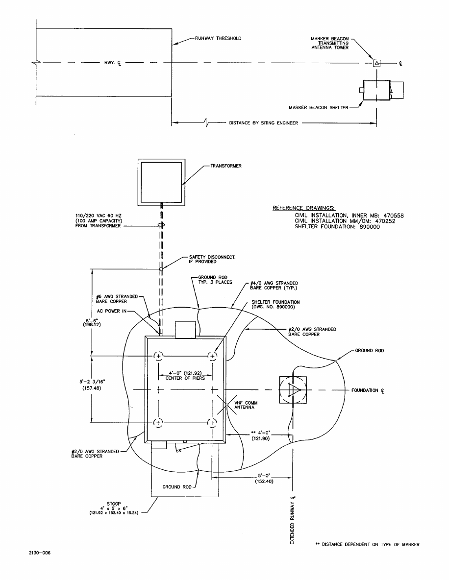
MODEL 2130 MARKER BEACON
8-2 Rev. A April, 2005
This document contains proprietary information and such information may not be disclosed to others for any
purposes without written permission from SELEX Sistemi Integrati Inc.
Figure 8-1 Typical Marker Beacon Site Details
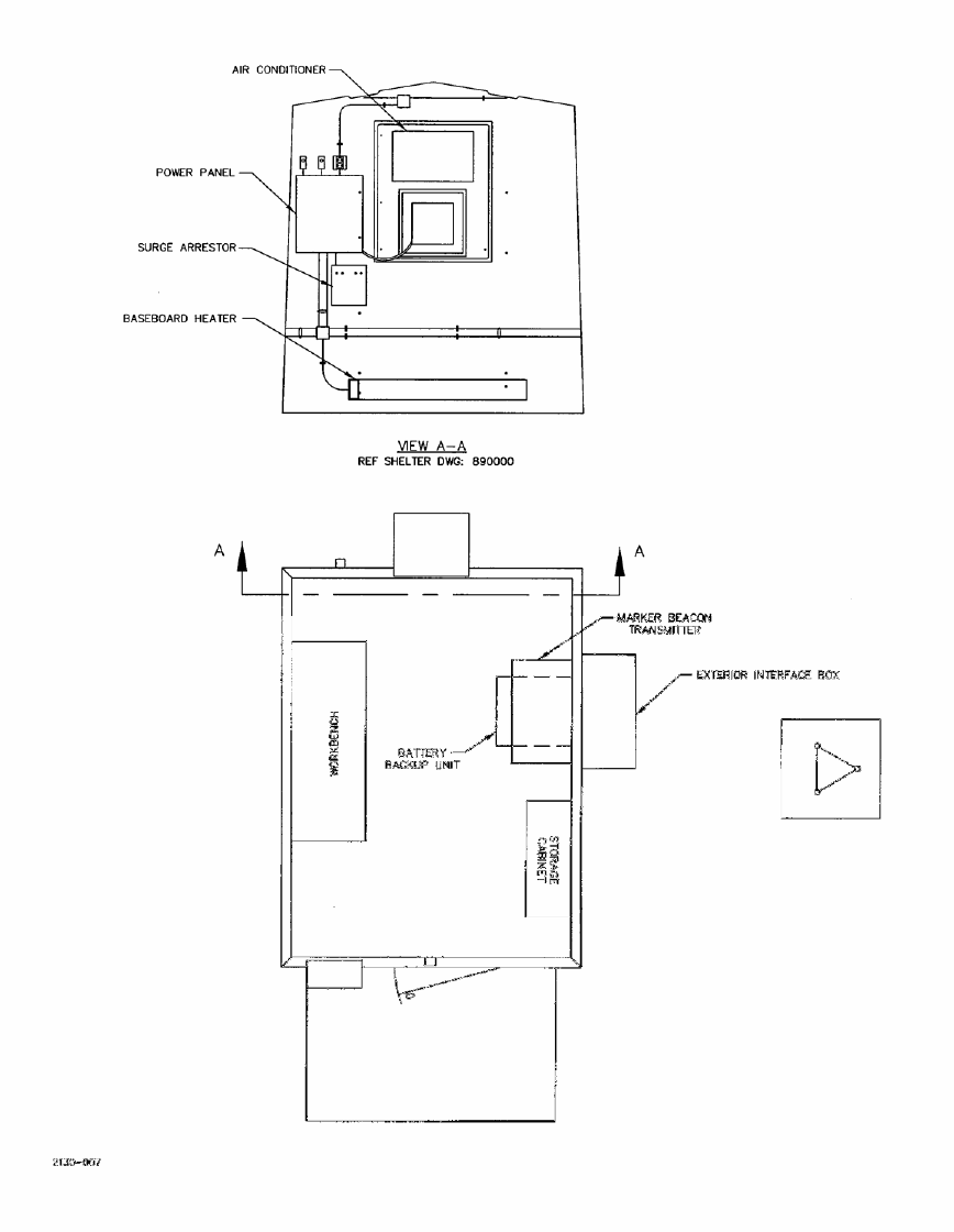
MODEL 2130 MARKER BEACON
Rev. A April, 2005 8-3
This document contains proprietary information and such information may not be disclosed to others for any
purposes without written permission from SELEX Sistemi Integrati Inc.
Figure 8-2 Typical Marker Beacon Shelter Details

MODEL 2130 MARKER BEACON
8-4 Rev. A April, 2005
This document contains proprietary information and such information may not be disclosed to others for any
purposes without written permission from SELEX Sistemi Integrati Inc.
8.5.2 Installation Kits
Refer to the following tables for kits required to install a Marker Beacon station.
Table 8-1 Marker Beacon Installation Kits
Part No. Description
950331-0000 Shelter, 6' x 8', federal
950281-0000 Shelter, 6' x 8', non-federal
470597-0001 Marker Beacon Installation Kit
Refer to Figure 11-9 for illustration and parts list.
470595-0001 Battery Backup Installation Kit
Refer to Figure 8-3 and 11-7 for illustration.
470592-0001 Single Yagi Transmitting Antenna and Tower Installation Kit
Refer to Table 7-9 for parts list.
Refer to Figure 11-4 for illustration and parts list.
470596-0001 Single Yagi Transmitting Antenna and Pole Mount Installation Kit
Refer to Table 7-10 for parts list.
Refer to Figure 11-8 for illustration and parts list.
8.5.3 Shelter Installation
Refer to a list of materials included in the Shelter Installation Kit (470240-0001).
a. See Figure 8-1. Using a crane and four nylon slings (20 feet long), position the equipment shelter (950281-0000 or
950331-0000) on the four concrete piers.
b. Attach the shelter to the pier anchor bolts using the 5/8-inch hardware, beveled washers, and tie-down plates.
c. Install shelter and antenna tower ground rods (900076-0000) and connect with No. 6 AWG bare copper wire (146006-
0000) as shown in Figure 8-1.
d. Connect main AC power to the shelter circuit breaker panel.
8.5.4 Marker Beacon Transmitter Cabinet Installation
Figure 11-9 gives the list of materials and installation details for the Marker Beacon Installation Kit (470597-0001).
a. Install Marker Beacon cabinet per Figure 11-9.
b. Install AC power to Marker Beacon cabinet. For wiring details, see interconnect diagram, Figure 11-11.
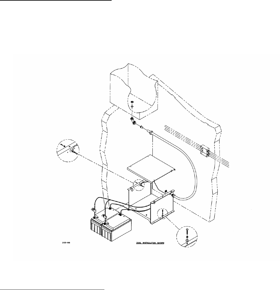
MODEL 2130 MARKER BEACON
Rev. A April, 2005 8-5
This document contains proprietary information and such information may not be disclosed to others for any
purposes without written permission from SELEX Sistemi Integrati Inc.
8.5.5 Battery Backup Assembly Installation
Refer to Figure 11-7 for a list of materials included in the battery backup installation kit (470595-0001). Refer to Figure 11-
11 for installation details.
a. Install the two batteries and connect wiring as shown in Figure 11-11, Marker Beacon interconnect diagram.
b. Install battery backup wiring between the Marker Beacon cabinet and the battery backup assembly. See Figure 11-12
interconnect diagram.
Figure 8-3 Battery Backup Installation Kit
8.5.6 Exterior Interfaced Box Installation
Refer to Figure 11-5 or Figure 11-6 for list of parts and installation details. The Exterior Interface kit is used in conjunction
with the tower or pole Yagi antenna installation kit (470593-0001 or 470594-0001).
a. Using a 2-1/4" hole saw, cut a hole in the center of the wall in which the Marker Beacon transmitter is attached.
b. Slide 2" x 12" threaded conduit into the hole. Install shouldered reducing washer and 2" locknut on each end of
threaded conduit. Apply sealing compound between washer and shelter wall. Tighten locknut.
c. Install Exterior Interface box on Unistrut rails per Figure 11-5 or 11-6.
d. Install threaded conduit, locknut, grounding bushing, and box connector through hole in top of Exterior Interface
box.

MODEL 2130 MARKER BEACON
8-6 Rev. A April, 2005
This document contains proprietary information and such information may not be disclosed to others for any
purposes without written permission from SELEX Sistemi Integrati Inc.
8.5.7 Single Yagi Transmitting Antenna and Tower Installation
Refer to Figure 11-4 for a list of materials included in the single Yagi antenna and tower installation kit (470592-0001).
a. Refer to Figure 11-3. Set a 10' foot tower base section on the foundation tower section buried in concrete. Ensure
that bottom of tower is down. Secure the two sections together with six machine screws (1/4-20 x 1-1/2"), flat -
washers (1 x 1/4), and hex nuts (1/4-20) supplied with item 10.
b. Secure three moisture caps (item 12) to the tower top.
c. Refer to Figure 11-4. Secure the two Unistrut mounting rails (item 8) to top of tower with clamps (item 9) as shown.
Before tightening the top rail, ensure that rail is level and centered. Do not tighten bottom rail until antenna plate
(item 10) is attached to upper rail.
d. Secure antenna plate (item 10) to top and bottom Unistrut rails (item 8) with four cap head screws (item 5), four lock
washers (item 3), eight flat washers (item 2), and four hex nuts (item 4). Tighten all rail clamps and attaching
hardware.
e. Install two clamps and U-bolts (item 20) to antenna mounting plate. Do not tighten.
f. See Figure 8-5 Yagi antenna assembly. Slide clamp (MP7) over antenna boom (MP8). Temporarily secure clamp
between the black and green painted lines on the boom.
NOTE
A diagram is supplied with the antenna. Information supplied on this drawing is to
be used as back up information to the following instructions.
g. Slide green (color painted on the casting) antenna element (MP5) over boom until it fits between the green lines on
the boom. Align and secure as shown.
h. Slide red antenna element (MP6) over the boom until it fits between the red lines on the boom. Align and secure as
shown.
i. A bronze casting is supplied with the antenna for mounting antenna to pole. This casting is a throw away item and
item 69 (302091-0000) in the kit is to be used instead. Slide clamp (MP7) over the boom and temporarily secure
between red antenna element and the end of the boom.
j. Slide black (MP2), blue (MP3), and yellow (MP4) over the boom until they fit between lines of same color on the
boom. Align and secure as shown.
k. Position antenna as shown and install balun (MP1) assembly. The loop side of balun has a bracket in which the bolt
requires seating in MP8.
l. See Figure 11-8. Install clamps, U-bolts, and attaching hardware to the antenna boom clamp. Do not tighten.
m. Install EMT pipe (item 19) and secure with clamps (item 20) and U-bolts (part of item 20).
n. Slide the antenna on to the EMT pipe (item 19) and secure with U-bolts supplied with the antenna.
o. After antenna is secured, use the siliconized acrylic caulk to secure the antenna boom cap (item 18).
p. Refer to Figure 11-8 and RF interconnect diagram in Figure 11-11. Route the antenna and monitoring cabling between
the Marker Beacon cabinet, the RF grounding box, and the antenna. Route ground wire to RF grounding box.
q. Refer to Figure 8-4. Secure antenna monitor assembly (item 21) to base of antenna with tie wraps (item 25).
r. Secure PVC conduit parts together using PVC cleaner (item 14) and adhesive (item 13).
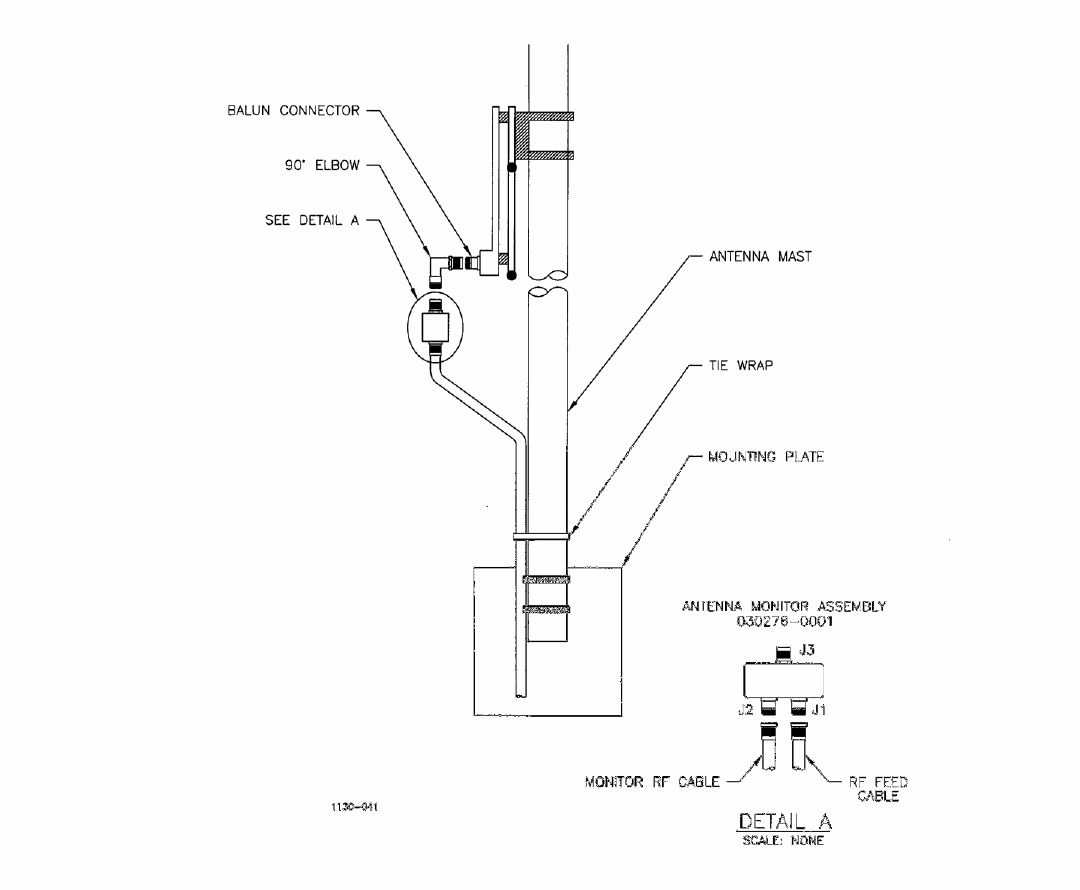
MODEL 2130 MARKER BEACON
Rev. A April, 2005 8-7
This document contains proprietary information and such information may not be disclosed to others for any
purposes without written permission from SELEX Sistemi Integrati Inc.
Figure 8-4 Antenna Monitor Assembly Mounting Details for Single Yagi Antenna
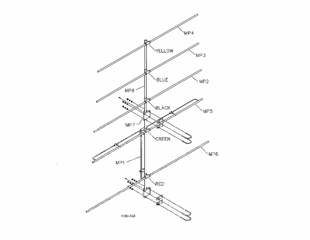
MODEL 2130 MARKER BEACON
8-8 Rev. A April, 2005
This document contains proprietary information and such information may not be disclosed to others for any
purposes without written permission from SELEX Sistemi Integrati Inc.
Figure 8-5 Yagi Antenna Assembly

MODEL 2130 MARKER BEACON
Rev. A April, 2005 8-9
This document contains proprietary information and such information may not be disclosed to others for any
purposes without written permission from SELEX Sistemi Integrati Inc.
8.6 Initial Start-up and Preliminary Testing
The following paragraphs detail the step-by-step procedures for initial start-up and preliminary testing of the Marker
Beacon. Procedures are also given for the setup using the Portable Maintenance Data Terminal (PMDT). The Marker
Beacon power levels, modulation, etc., have been set at the factory to their nominal values. Check or set each of the
levels as described in the following paragraphs.
8.6.1 Electronics Preparation
The Marker Beacon equipment was tested at the factory and met all production requirements. However, due to handling
and shipping actions since that time, the customer must take precautions during the initial system turn on.
a. Place AC power switch to the OFF position.
b. Remove the top cover to the BCPS.
c. Measure the AC voltage between TB1-1 and TB1-2. Verify that the AC voltage is in compliance with Table 1-1.
d. Turn on AC power Marker 1 AC. Measure the AC voltage between TB1-8 and TB1-9. Verify that the AC voltage is in
compliance with Table 1-1.
e. Turn on Marker 1 DC. Measure the DC voltage between TB2-6(-) and TB2-9(+). Verify compliance with Table 1-1.
f. Turn on AC power Marker 2 AC. Measure the AC voltage between TB1-11 and TB1-12. Verify that the AC voltage is
in compliance with Table 1-1.
g. Turn on Marker 2 DC. Measure the DC voltage between TB2-7(-) and TB2-10(+). Verify compliance with Table 1-1.
h. Replace cover.
8.6.2 Initial Start-Up
See Section Error! Reference source not found. to place the Marker Beacon in operation. The Marker Beacon is
software-controlled, operated by using the Windows screens and menus per Section Error! Reference source not found.
of this manual.
8.6.2.1 PMDT Hook-Up
The Marker Beacon is shipped from the factory with passwords preset for Level 1, Level 3, and Level 4 as follows:
User ID Password
Level 1: GUEST (no password required for Level 1
access)
Level 3: SEC3 THREE
Level 4: SEC4 FOUR
Level 1 access is read only. Level 2 access is read and issue selected commands. Level 3 access is read/write, except for
Security Code information. Level 4 has unrestricted access. Refer to Section Error! Reference source not found. for
procedures to change system password and security code. Connect the serial communication port on the PMDT to the 25
pin D-connector on the right side of the transmitter cabinet. Power up the PMDT and load the software.
To install the PMDT software, follow this procedure:
a. Insert the PMDT Installation disk (978178 disk 1) into the A drive of the PMDT PC
b. Click the Start button, then Run.
c. Enter the following command line:
A:\SETUP
d. Press the OK button to start the installation of the PMDT application.
e. Follow the prompts, accepting the defaults for program locations and folder names. The PMDT application will be
installed into the C:\Program Files\SELEX SI\2100 PMDT directory, with shortcuts to it copied to the Desktop and the
MODEL 2130 MARKER BEACON
8-10 Rev. A April, 2005
This document contains proprietary information and such information may not be disclosed to others for any
purposes without written permission from SELEX Sistemi Integrati Inc.
Start >> Programs Menu.

MODEL 2130 MARKER BEACON
Rev. A April, 2005 8-11
This document contains proprietary information and such information may not be disclosed to others for any
purposes without written permission from SELEX Sistemi Integrati Inc.
8.6.3 AC/DC Voltage and Current Checks
Log on to the PMDT and view RMS>>Data> A/D Data and verify that the data values are within the established limits.
8.6.4 RF Forward Power, Reflected RF Power, and VSWR Checks
Refer to Section 5 for the procedures to check RF forward power, reflected RF power, and VSWR.
8.6.5 Modulation Percentage and Keying Checks
Refer to Section 5 for the procedures to check modulation percentage and keying.
8.7 Installation Verification Tests
The following paragraphs describe a one-time procedure that verifies that each of the settings.
8.7.1 Keying Verification
The identification keying code normally is set at the factory according to the requirements of each Marker Beacon.
8.7.2 Verification of Alarm and alert settings
8.7.2.1 RF Forward Power Alarm Point
Refer to Section 5 for the procedure to verify and set the RF forward power alarm point.
8.7.2.2 VSWR Alarm Point
Refer to Section 5 for the procedure to verify and set the VSWR alarm point.
8.7.2.3 External Monitor Alarm Points
Refer to Section 5 for the procedure to verify and set the external monitor alarm points.
8.7.2.4 Alarm Delay Time and Auto-Restart Delay Time
Refer to Section 5 for the procedure to verify and set the alarm delay time and auto-restart delay time.
8.7.2.5 Percent Modulation Scale Factor Circuit
Refer to Section 5 for the procedure to verify and set the modulation percentage scale factor circuitry.

MODEL 2130 MARKER BEACON
8-12 Rev. A April, 2005
This document contains proprietary information and such information may not be disclosed to others for any
purposes without written permission from SELEX Sistemi Integrati Inc.
8.8 USB-Serial Driver Installation
The PMDT interface on the 2130 MB RMS CCA is implemented using USB-Serial converter circuitry, based on the FTDI
FT232BM IC. When the navaid is powered up, and the USB cable is connected to the PMDT computer, Windows should
automatically detect the new USB device and install the appropriate driver, activating the new COM port.
In the event that the driver isn’t automatically installed, the following procedure should be used.
a. Locate the FTDI USB Driver. The driver is typically copied to the same directory that the PMDT.EXE file is
located (ie. C:\Program Files\SELEX SI\PMDT\FTDI USB Driver\*.*. Alternatively, the driver can be downloaded
from FTDI’s website: www.FTDIChip.com. Note that only the VCP type of driver for the FT232BM device should
be used.
b. When Windows detects the new USB device and prompts for the proper driver, select “Install from a list or
specific location” option and press Next.
c. Select only the “Include this location in the search” option and browse to locate the folder containing the driver
(See step #1 above). Then press Next to install the driver.

MODEL 2130 MARKER BEACON
Rev. A April, 2005 8-13
This document contains proprietary information and such information may not be disclosed to others for any
purposes without written permission from SELEX Sistemi Integrati Inc.
d. The driver will be installed, assigning the USB port to an available COM port. Press Finish to close the Hardware
Installation Wizard.
e. To use this serial port for the PMDT, start the PMDT application.
f. Select System>>PMDT Setup and select the USB Serial Port as the Navaid Direct COM Port.
8.8.1 USB-Serial COM Port Notes
The user should be familiar with the following operational notes related to using the USB-Serial COM Port.
a. The USB-Serial Port is only active in the PMDT PC while the USB cable is connected between the PMDT and the
navaid, and the navaids is powered up. Powering down the system, or removing the cable will remove the USB
COM Port. If this is done while logged into the navaid, the user must Logout/Disconnect in the PMDT, and wait
for the disconnect to be finalized. When the USB-Serial Port is re-activated (by either powering up the navaid, or
reconnecting the cable) then the user can once again login to the navaid with the
System>>Connect>>Navaid>>Direct menu option.
b. Changing to another USB port on the PC could cause the USB driver to be assigned to another COM port. The
currently active USB-Serial COM Port can always be determined and selected with the Navaid Direct COM Port
setting in the PMDT’s System>>PMDT Setup screen. To simplify this connection, always use the same USB
port on the PMDT computer for the PMDT-navaid link.

MODEL 2130 MARKER BEACON
Rev. A April, 2005 9-1
This document contains proprietary information and such information may not be disclosed to others for any
purposes without written permission from SELEX Sistemi Integrati Inc.
9. SOFTWARE
9.1 Introduction
Software documentation contains proprietary information and such information is not applicable to this manual.
MODEL 2130 MARKER BEACON
9-2 Rev. A April, 2005
This document contains proprietary information and such information may not be disclosed to others for any
purposes without written permission from SELEX Sistemi Integrati Inc.
THIS SHEET INTENTIONALLY BLANK

MODEL 2130 MARKER BEACON
Rev. A April, 2005 10-1
This document contains proprietary information and such information may not be disclosed to others for any
purposes without written permission from SELEX Sistemi Integrati Inc.
10. TROUBLESHOOTING SUPPORT DATA
10.1 Introduction
This section contains a list of drawings useful during installation and maintenance. Copies of all drawings can be found
in the CDROM version of the manual. Drawings that are needed during installation are provided in paper form within the
appropriate kit. Paper copies of all drawings can be purchased by contacting the SELEX Sistemi Integrati Inc. Customer
Service organization.
Description Drawing No. Figure Page #
Marker Beacon System, Family Tree (sheet 1 only) 502070 11-1 11-3
Civil Installation Kit, Middle/ Outer Marker Beacon 470252 11-2 11-5
Civil Installation Kit, Inner Marker Beacon 470558 11-3 11-7 to 9
Antenna Kit, Tower Mount 470592 11-4 11-11 to 15
Exterior Interface Kit, Inner Marker Beacon 470593 11-5 11-17 to 21
Exterior Interface Kit, Middle/Outer Marker Beacon 470594 11-6 11-23 to 27
Battery Backup Kit 470595 11-7 11-29 to 31
Antenna Kit, Pole Mount 470596 11-8 11-33 to 37
Transmitter Installation Kit 470597 11-9 11-39 to 41
Marker Beacon Radio Link Kit (Optional) 470602 11-10 11-43 to 49
Marker Beacon System Interconnect Diagram 002130-9001 11-11 11-51 to 53
Amp/Monitor CCA, Schematic Diagram 012141-9001 11-12 11-63 to 69
Battery Control Power Supply CCA, Schematic Diagram 012142-9001 11-13 11-71 to 75
Local Control Unit CCA, Schematic Diagram 012143-9001 11-14 11-77 to 83
Remote Monitoring System CCA, Schematic Diagram 012147-9001 11-15 11-85 to 91
Far Field Monitor Transmitter CCA, Schematic Diagram 012130-9001 11-16 11-55 to 61
MODEL 2130 MARKER BEACON
10-2 Rev. A April, 2005
This document contains proprietary information and such information may not be disclosed to others for any
purposes without written permission from SELEX Sistemi Integrati Inc.
THIS SHEET INTENTIONALLY BLANK