Semiconductor 2006002 HF RFID Printer User Manual
Taiwan Semiconductor Co. Ltd. HF RFID Printer
UserManual.wiki
>
Semiconductor
>
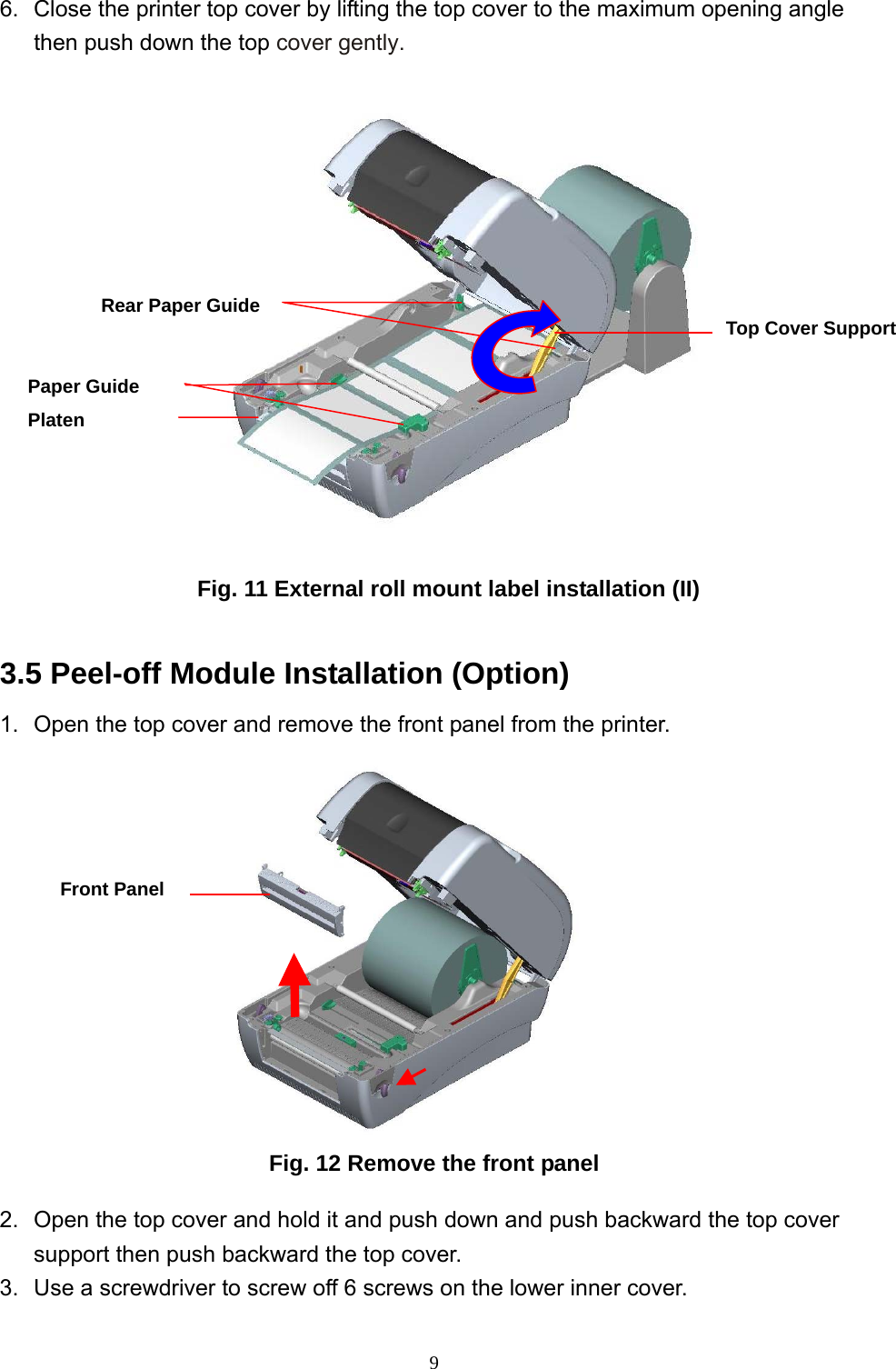
2006002 User Manual
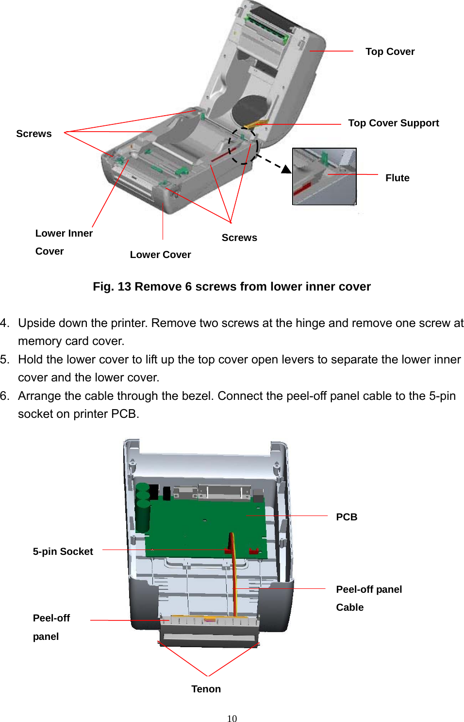
user manual
Navigation menu
Upload a User Manual
Namespaces
Wiki Guide
HTML
PDF
Info
Views
User Manual
Discussion / Help
Navigation