Senao Co 2511CD Wireless LAN PC Card User Manual About AirLAN
Senao International Co Ltd Wireless LAN PC Card About AirLAN
UserManual.wiki
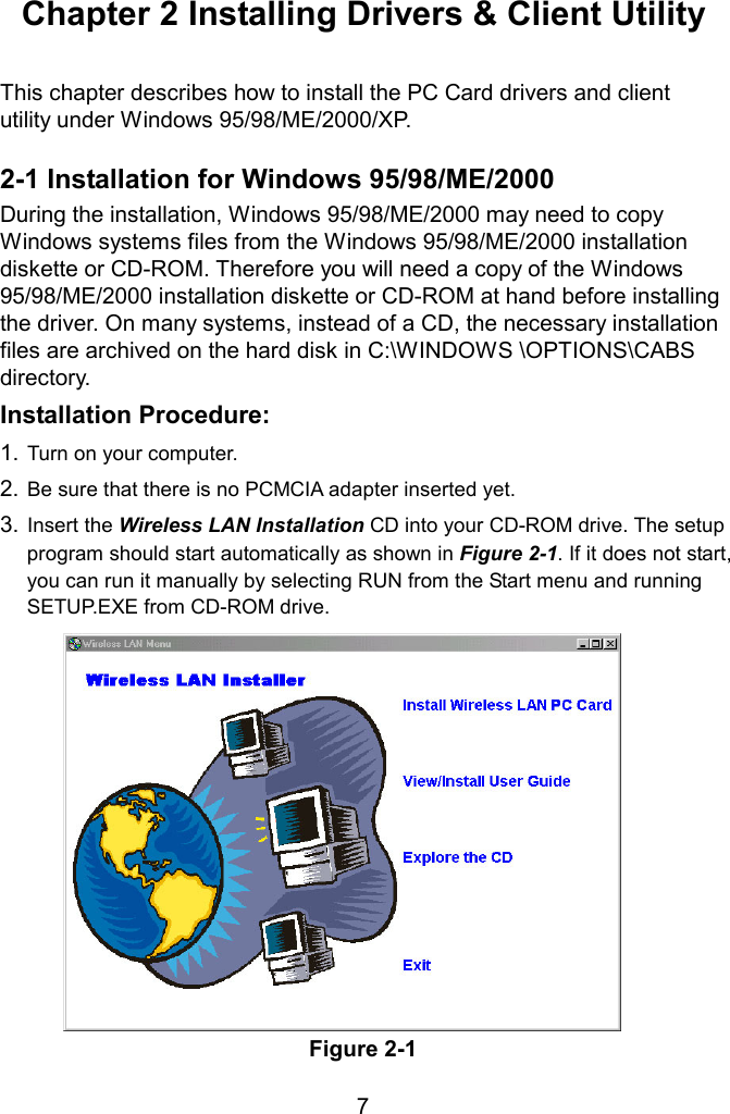
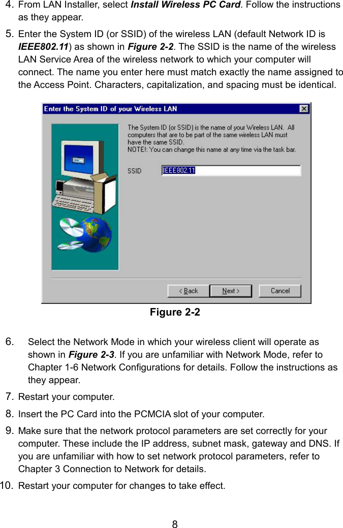
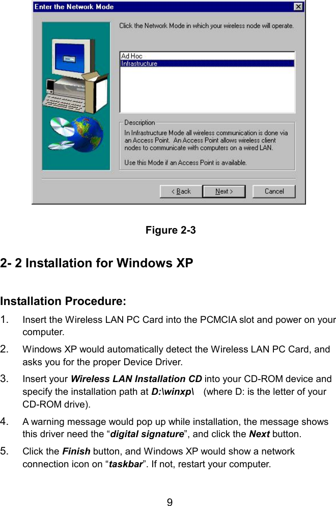
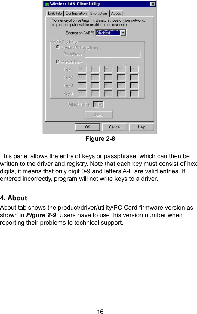
>
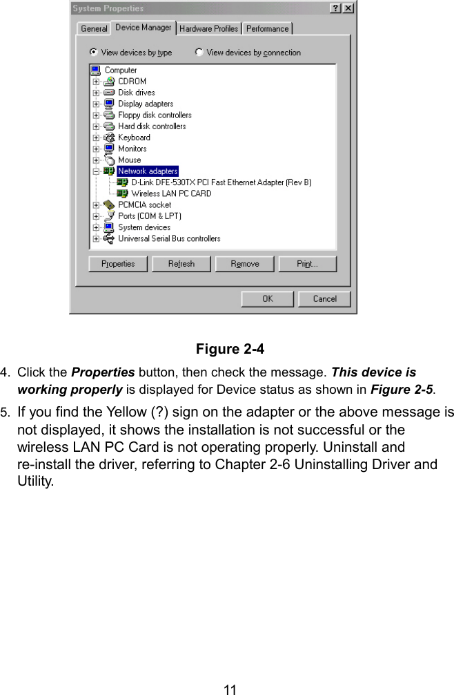
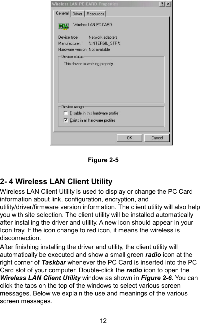
Senao Co
>
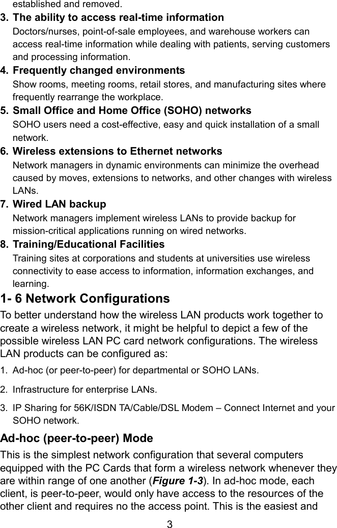
2511CD User Manual
Manual
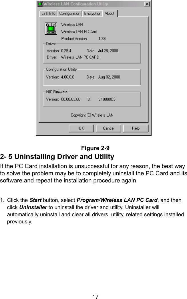
Navigation menu
Upload a User Manual
Namespaces
Wiki Guide
HTML
PDF
Info
Views
User Manual
Discussion / Help
Navigation