Senao Co 2511SR 2-Port Wireless Router User Manual Broadband IP Sharer
Senao International Co Ltd 2-Port Wireless Router Broadband IP Sharer
Senao Co >
Manual
Senao
2-Port Switch Wireless Router
User Guide
Before operating the unit, please read this manual thoroughly, and retain it for future reference.
Model No. SL-2511SR
Copyright
The contents of this publication may not be reproduced in any part or as a whole, stored,
transcribed in an information retrieval system, translated into any language, or transmitted
in any form or by any means, mechanical, magnetic, electronic, optical, photocopying,
manual, or otherwise, without the prior written permission.
Trademarks
All product, company, brand names are trademarks or registered trademarks of their
respective companies. They are used for identification purpose only. Specifications are
subject to be changed without prior notice.
-1-
FCC Interference Statement
This equipment has been tested and found to comply with the limits for a Class B digital
device pursuant to Part 15 of the FCC Rules. These limits are designed to provide
reasonable protection against radio interference in a commercial environment. This
equipment can generate, use and radiate radio frequency energy and, if not installed and
used in accordance with the instructions in this manual, may cause harmful interference to
radio communications. Operation of this equipment in a residential area is likely to cause
interference, in which case the user, at his own expense, will be required to take whatever
measures are necessary to correct the interference.
CE Declaration of Conformity
This equipment complies with the requirements relating to electromagnetic compatibility,
EN 55022/A1 Class B, and EN 50082-1. This meets the essential protection requirements
of the European Council Directive 89/336/EEC on the approximation of the laws of the
member states relation to electromagnetic compatibility.
-2-
This transmitter must not be co-located or operating in conjunction with any other antenna
or transmitter.
Table of Contents
Chapter 1 Introduction...............................................................................4
Functions and Features.........................................................................4
1.2 Packing List....................................................................................5
Chapter 2 Hardware Installation................................................................6
2.1 Panel Layout...................................................................................6
2.2 Procedure for Hardware Installation ..............................................8
Chapter 3 Configuring Wireless Access Point.........................................11
3.1 Start-up and Log in.......................................................................11
3.2 System Info...................................................................................13
3.3 Toolbox.........................................................................................14
3.4 Primary Setup...............................................................................15
3.5 DHCP Server ................................................................................18
3.6 MAC Address Control..................................................................20
Appendix A TCP/IP Configuration for Windows 95/98..........................23
A.1 Install TCP/IP Protocol into Your PC..........................................23
A.2 Set TCP/IP Protocol for Working with This Device....................25
A.3 Specifications...............................................................................32
A.4 Regulatory Compliance Information...........................................34
-3-

Chapter 1 Introduction
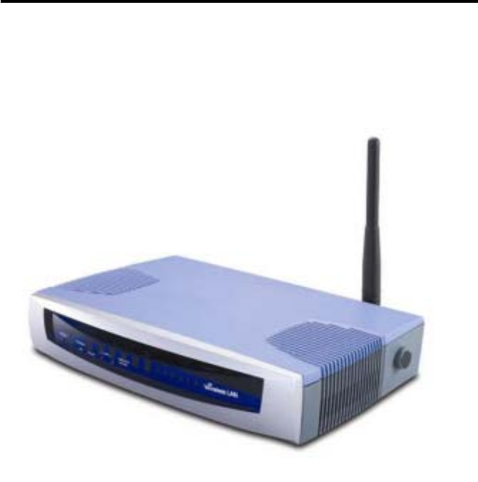
Congratulations on your purchase of this outstanding Wireless Access Point. This product
is specifically designed for Small Office and Home Office needs. It provides a solution for
building a LAN and sharing resources with or without wire, and is easy to configure and
operate even for non-technical users. Instructions for installing and configuring this
product can be found in this manual. Before you install and use this product, please read
this manual carefully for fully exploiting the functions of this product.
Functions and Features
High speed for wireless LAN connection
11Mbps data rate by incorporating Direct Sequence Spread Spectrum (DSSS).
Roaming
Provides seamless roaming within the IEEE 802.11b WLAN infrastructure.
IEEE 802.11b compatible
Allowing inter-operation among multiple vendors.
Auto fallback
11M, 5M, 2M, 1M data rate with auto fallback.
Auto-sensing Ethernet Switch
Equipped with a 2-port auto-sensing Ethernet switch.
DHCP server supported
All of the networked computers can retrieve TCP/IP settings automatically from
this product.
Web-based configuring
Configurable through any networked computer’s web browser.
-4-

MAC Address Access Control supported
Allows you to assign different access right for different users.
Firmware Upgradable
Provides firmware upgrade via Web Browser or Windows Application.
1.2 Packing List
Wireless Access Point unit
Installation CD-ROM
Power adapter
CAT-5 UTP Fast Ethernet cable
-5-
Chapter 2 Hardware Installation
2.1 Panel Layout
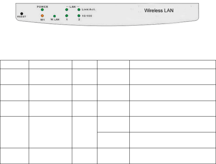
2.1.1. Front Panel
Figure 2-1 Front Panel
LED:
LED Function Color Status Description
POWER Power indication Green On Power is being applied to this
product.
M1 System status 1 Orange Blinking This product is functioning
properly.
WLAN Wireless activity Green Blinking Sending or receiving data via
wireless
On An active station is connected to
the corresponding LAN port.
Link/Act.
1~2 Link status Green
Blinking The corresponding LAN port is
sending or receiving data.
10/100 Data Rate Green On Data is transmitting in 100Mbps
on the corresponding LAN port.
Port:
RESET To reset system settings to factory defaults, please follow the steps:
1. Power off the device,
2. Press the reset button and hold,
3. Power on the device,
4. Keep the button pressed about 5 seconds,
5. Release the button,
6. Watch the M1 LED, they will flash 8 times and then M1 flash once
-6-
per second.
-7-
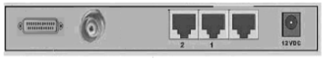
2.1.2. Rear Panel
Figure 2-2 Rear Panel
Ports:
Port Description
12VDC Power inlet: DC 12V, 1.5A (minimum)
Port 1-2 the ports where you will connect networked computers and other
devices.
Connector TNC connector
RS-232 RS-232 for ISDN/TA modem
2.2 Procedure for Hardware Installation
1. Decide where to place your Wireless Access Point
You can place your Wireless Access Point on a desk or other flat surface, or you can
mount it on a wall. For optimal performance, place your Wireless Access Point in the
center of your office (or your home) in a location that is away from any potential
source of interference, such as a metal wall or microwave oven.
-8-
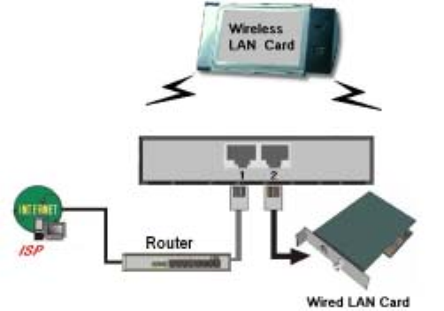
2. Setup LAN connection
a. Wired LAN connection: connect an Ethernet cable from your computer’s Ethernet
port to one of the LAN ports (number 1-2) on the AP. Repeat the process to
connect other computers to the AP. If you need to connect more than two
computers to the AP, use a 10/100 Fast Ethernet switch (preferred) or hub and
connect the Ethernet cable from the AP to the switch/hub’s UPLINK port. You
may need to switch on the UPLINK feature on the switch/hub. The AP supports
up to 253 network computers and devices.
b. Wireless LAN connection: locate this product at a proper position to gain the best
transmits performance.
Figure 2-3 Setup of LAN connections for this product.
Note: If an UPLINK port is not available, simply connect a
crossover Ethernet cable from the AP to the switch/hub.
-9-
3. Power on
Connecting the power cord to power inlet and turning the power switch on, this
product will automatically enter the self-test phase. When it is in the self-test phase,
the indicators M1 will be lighted ON for about 10 seconds, and then M1 will be
flashed 3 times to indicate that the self-test operation has finished. Finally, the M1
will be continuously flashed once per second to indicate that this product is in normal
operation.
-10-
Chapter 3 Configuring Wireless Access Point
This product provides Web based configuration scheme, that is, configuring by your Web
browser, such as Netscape Communicator or Internet Explorer. This approach can be
adopted in any MS Windows, Macintosh or UNIX based platforms.
3.1 Start-up and Log in
Activate your browser, and disable the proxy or add the IP address of this product into
the exceptions. Then, type this product’s IP address (the factory setting is
192.168.123.254) in the Location (for Netscape) or Address (for IE) field and press
-11-
ENTER.
After the connection is established, you will see the web user interface of this product.
There are two appearances of web user interface: for general users and for system
administrator.
To log in as an administrator, enter the system password (the factory setting is ”admin”) in
the System Password field and click on the Log in button. If the password is correct, the
web appearance will be changed into administrator configure mode. As listed in its main
menu, there are several options for system administration.
-12-
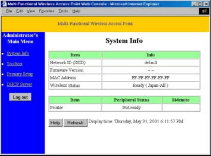
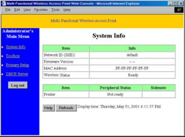
3.2 System Info.
This option provides the function for observing this product’s settings and working status:
A. Network ID (SSID): The current setting of SSID
B. Firmware Version: The current firmware version on this device
C. MAC Address: The MAC address of this device
-13-
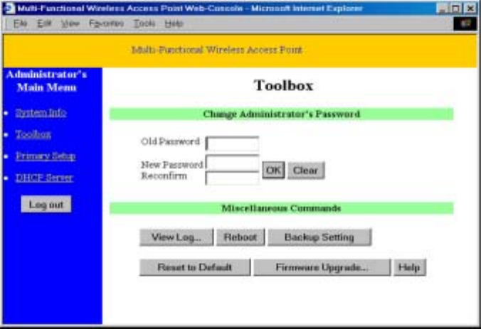
3.3 Toolbox
This option enables you to change the administrator password.
There are some useful buttons in this page:
View Log View the system logs
Reboot Reboot this device
Backup Setting You can backup your settings by clicking this button and
save it as a bin file. Once you want to restore these settings,
please click Firmware Upgrade button and use the bin file
you saved.
Reset to Default Reset the settings of this device to the default values
Firmware Upgrade Prompt the administrator for a file and upgrade it to this
device
Note: we strongly recommend you to change the system password for security
reason.
-14-
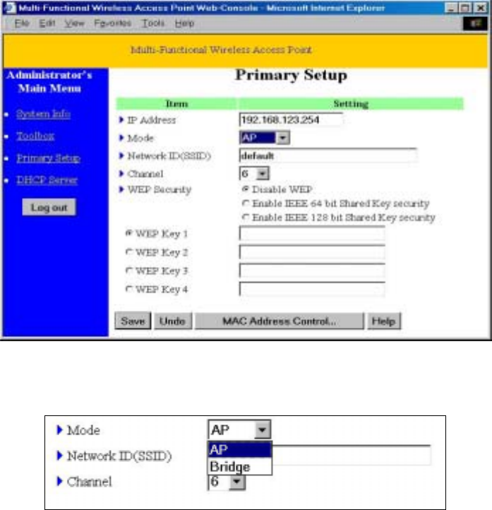
3.4 Primary Setup
This option is primary to enable this product to work properly.
1. IP Address: the IP address of this device. You can change it if necessary.
2. Mode: the operating mode of this device. The default mode is “AP”, which is the
normal operation mode of a wireless AP. You can change it to the “Bridge” mode if
you want this product to work as a wireless bridge* .
3. Network ID(SSID): Network ID is used for identifying the Wireless LAN (WLAN).
Client stations can roam freely over this product and other Access Points that have the
-15-

same Network ID. (The factory setting is “default”).
Note: This item won’t take effect in “Bridge” mode.
4. Channel: The radio channel number. The permissible channels depend on the
Regulatory Domain.
The factory setting is as follows:
USA/Canada
Europe/Australia (ETSI)
Japan (All)
Channel 6
Spain, France Channel 10
Japan Channel 14
5. WEP Security: Select the data privacy algorithm you want. Enabling the security can
protect your data while it is transferred from one station to another. The standardized
IEEE 802.11 WEP (64-bit or 128-bit) is used here.
6. WEP Key 1, 2, 3 & 4: When you enable the 64-bit or 128-bit WEP key security,
please select one WEP key to be used and then input 10 or 26 hex-decimal (0-9, A-F)
digits.
MAC Access Control Setup MAC addresses to control which wireless clients can
associate to the wireless LAN.
*Wireless Bridge:
Two of this device will be able to communicate with each other when they are
working in the “Bridge” Mode. You can connect two wired LANs together via wireless
connection with wireless bridge function. The connection is as follows:
-16-
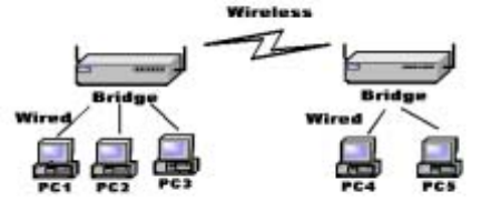
To let two devices communicate with each other via wireless, just set these two
devices to “Bridge” mode and set the “Channel” to the same channel number.
Note: This device can’t be a wireless AP when it is operating as a wireless bridge.
This means there is no wireless client can associate to this device when it’s in the bridge
mode.
B“Bridge” mode. “Bridge” mode.
-17-
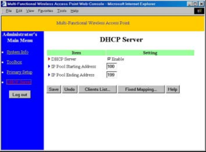
3.5 DHCP Server
The settings of a TCP/IP environment include host IP, Subnet Mask, Gateway, and DNS
configurations. It is not easy to manually configure all the computers and devices in your
network. Fortunately, DHCP Server provides a rather simple approach to handle all these
settings. This product supports the function of DHCP server. If you enable this product’s
DHCP server and configure your computers as “automatic IP allocation” mode, then when
your computer is powered on, it will automatically load the proper TCP/IP settings from
this product. The settings of DHCP server include the following items:
1. DHCP Server: Check “Enable” to enable the DHCP server function. All the settings
in this page will take effect only if “Enable” is checked.
-18-
2. Range of IP Address Pool: Whenever there is a request, the DHCP server will
automatically allocate an unused IP address from the IP address pool to the
requesting computer. You must specify the starting and ending address of the IP
address pool.
Clients List List the current mapping of the IP and MAC address for
each DHCP client.
Fixed Mapping In general, DHCP server assigns an IP address chosen from
the IP addresses pool randomly. Fixed Mapping allows you
to assign a specific IP address to the specified MAC
address.
-19-
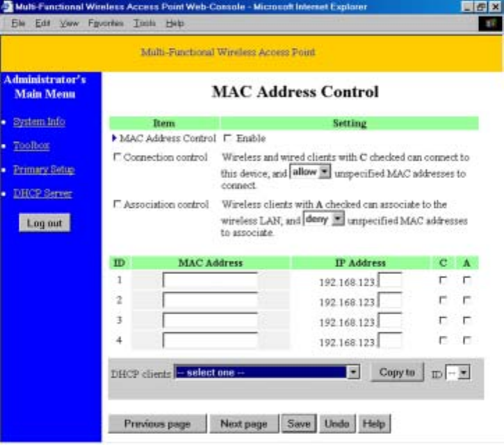
3.6 MAC Address Control
MAC Address Control allows you to assign different access right for different users and to
assign a specific IP address to a certain MAC address.
MAC Address Control Check “Enable” to enable the “MAC Address Control”. All of
the settings in this page will take effect only when “Enable”
is checked.
Connection control Check "Connection control" to enable the controlling of
which wired and wireless clients can connect to this device. If
-20-

a client is denied to connect to this device, it means the client
can't access to the Internet either. Choose "allow" or "deny"
to allow or deny the clients, whose MAC addresses are not in
the "Control table" (please see below), to connect to this
device.
Association control Check "Association control" to enable the controlling of
which wireless client can associate to the wireless LAN. If a
client is denied to associate to the wireless LAN, it means the
client can't send or receive any data via this device. Choose
"allow" or "deny" to allow or deny the clients, whose MAC
addresses are not in the "Control table", to associate to the
wireless LAN.
Control table "Control table" is the table at the bottom of the "MAC
Address Control" page. Each row of this table indicates the
MAC address and the expected IP address mapping of a client.
There are four columns in this table:
MAC Address MAC address indicates a specific client.
IP Address Expected IP address of the corresponding
client. Keep it empty if you don't care its
IP address.
C When "Connection control" is checked,
check "C" will allow the corresponding
client to connect to this device.
A When "Association control" is checked,
check "A" will allow the corresponding
client to associate to the wireless LAN.
-21-

In this page, we provides the following Combobox and button to help you to input the
MAC address.
You can select a specific client in the “DHCP clients” Combobox, and then click on the
“Copy to” button to copy the MAC address of the client you select to the ID selected in
the “ID” Combobox.
Previous page and Next Page To make this setup page simple and clear, we
have divided the “Control table” into several
pages. You can use these buttons to navigate to
different pages.
-22-
Appendix A TCP/IP Configuration for Windows 95/98
This section introduces you how to install TCP/IP protocol into your personal computer.
And suppose you have been successfully installed one network card on your personal
computer. If not, please refer to your network card manual. Moreover, the Section A.2
tells you how to set TCP/IP values for working with this device correctly.
A.1 Install TCP/IP Protocol into Your PC
1. Click Start button and choose Settings, then click Control Panel.
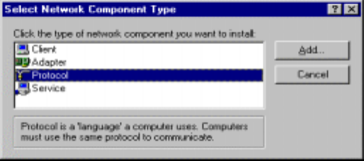
2. Double click Network icon and select Configuration tab in the Network window.
3. Click Add button to add network component into your PC.
4. Double click Protocol to add TCP/IP protocol.
-23-
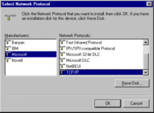
5. Select Microsoft item in the manufactures list. And choose TCP/IP in the Network
Protocols. Click OK button to return to Network window.
6. The TCP/IP protocol shall be listed in the Network window. Click OK to complete the
install procedure and restart your PC to enable the TCP/IP protocol.
-24-
A.2 Set TCP/IP Protocol for Working with This Device
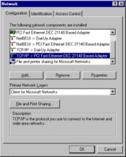
1. Click Start button and choose Settings, then click Control Panel.
2. Double click Network icon. Select the TCP/IP line that has been associated to your
network card in the Configuration tab of the Network window.
3. Click Properties button to set the TCP/IP protocol for this device.
4. Now, you have two setting methods:
A. Get IP via DHCP server
-25-
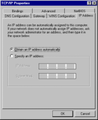
a. Select Obtain an IP address automatically in the IP Address tab.
-26-
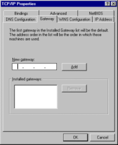
b. Don’t input any value in the Gateway tab.
-27-
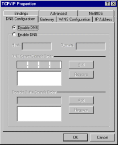
c. Choose Disable DNS in the DNS Configuration tab.
-28-
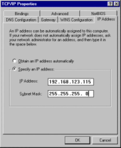
B. Configure IP manually
a. Select Specify an IP address in the IP Address tab. The default IP address
of this product is 192.168.123.254. So please use 192.168.123.xxx (xxx is
between 1 and 253) for IP Address field and 255.255.255.0 for Subnet
Mask field.
-29-
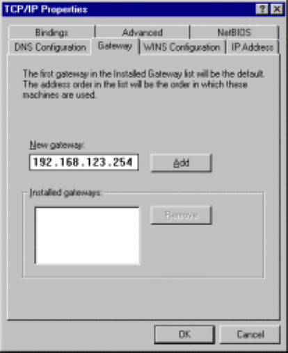
b. In the Gateway tab, add the IP address of the gateway you use in the New
gateway field and click Add button.
-30-
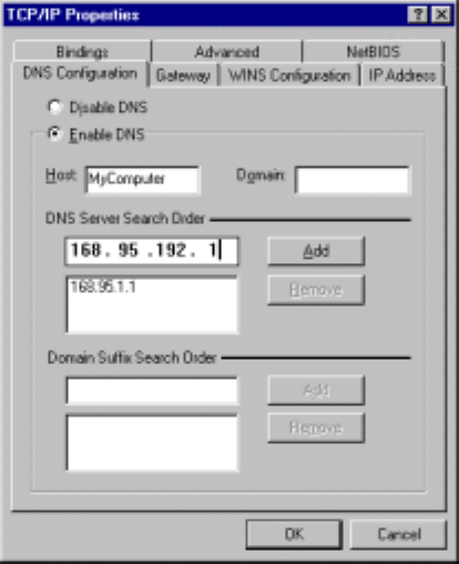
c. In the DNS Configuration tab, add the DNS values which are provided by
the ISP into DNS Server Search Order field and click Add button.
-31-

A.3 Specifications
General
Data Transfer Rate 11, 5.5, 2 and 1 Mbps, Auto Fall-Back
Range (open environment)
11 Mbps – 250m
5.5 Mbps – 300m
2 Mbps – 400m
1 Mbps – 600m
Regulation Certifications FCC Part 15, ETSI 300/328/CE
Compatibility Fully interoperable with IEEE802.11b
compliant products
LED Indicators Power, WLAN active, Ethernet Link
active , WAN link active
Network Information
Interface 10Mbps RJ-45 for DSL/Cable Modem
10/100 RJ45 Port for LAN
RS-232 for ISDN TA/modem
TNC connector
Roaming Seamless roaming (IEEE802.11b
compliant)
IP Sharing Supports PAT/NAT
Security 64/128-bit WEP data encryption
Management
Remote Configuration Web
Firmware Upgrade Upgrade via Web
IP Auto-configuration Supports DHCP client/server
Radio
Frequency Band 2.4 – 2.484 GHz
Radio Type Direct Sequence Spread Spectrum
(DSSS)
Modulation CCK (11, 5.5Mbps)
DQPSK (2Mbps)
DBPSK (1Mbps)
Operation Channels 11 for North America, 14 for Japan,
13 for Europe, 2 for Spain, 4 for France
RF Output Power 16dBm + 2dBm
Antenna High sensitivity antenna
-32-

Environmental
Temperature Range 0 to 55 C, 32 to 131 F (operating)
-20 to 80 C ,-4 to 176 F (storage)
Humidity (non-condensing) 5% to 95% typical
Physical Specifications
Dimensions 145(L) mm x 220(W) mm x 40(H) mm
Weight 750 g
-33-
A.4 Regulatory Compliance Information
Radio Frequency Interference Requirements
This device complies with Part 15 of FCC Rules and Canada RSS-210.
Operation is subject to the following conditions:
1. This device may not cause harmful interference.
2. This device must accept any interference received, including interference
that may cause undesired operation.
3. To comply with RF safety requirements, you must maintain a distance of 20
cm from the antenna when operating the device.
4. This transmitter must not be co-located or operating in conjunction with any
other antenna or transmitter.
Interference Statement
This equipment has been tested and found to comply with the limits for a Class B
digital device, pursuant to Part 15 of the FCC Rules, These limits are designed to
provide reasonable protection against harmful interference in a residential
installation. This equipment generates, uses and can radiate radio frequency
energy and, if not installed and used in accordance with the instructions, may
cause harmful interference to radio communications. However, there is no
guarantee that interference will not occur in a particular installation. If this
equipment does cause harmful interference to radio or television reception, which
can be determined by turning the equipment off and on, the user is encouraged to
try to correct the interference by one of the following measures:
Reorient or relocate the receiving antenna.
Increase the separation between the equipment and receiver.
Connect the equipment into an outlet on a circuit different from that to which the receiver is
connected.
Consult the dealer or an experienced radio/TV technician for help.
FCC Caution: To assure continued compliance, (example – use only shielded
interface cables when connecting to computer or peripheral devices). Any changes
or modifications not expressly approved by the party responsible for compliance
could void the user’s authority to operate this equipment.
-34-