Senao Co 30V214 Atheros11g Card Bus Adapter User Manual 3054cb aries2 User s Manual
Senao International Co Ltd Atheros11g Card Bus Adapter 3054cb aries2 User s Manual
UserManual.wiki
>
Senao Co
>
30V214 User Manual
Manual
Navigation menu
Upload a User Manual
Namespaces
Wiki Guide
HTML
PDF
Info
Views
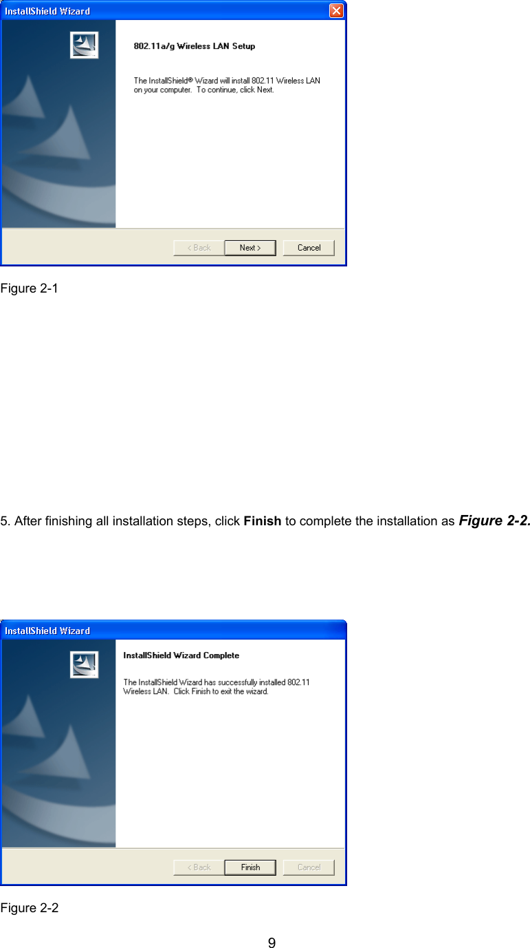
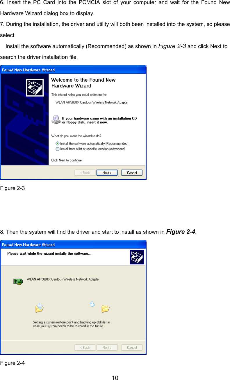
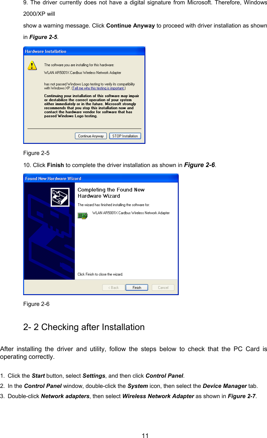
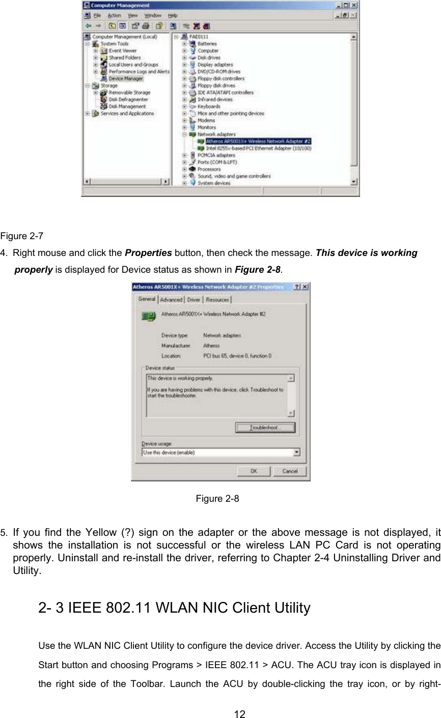
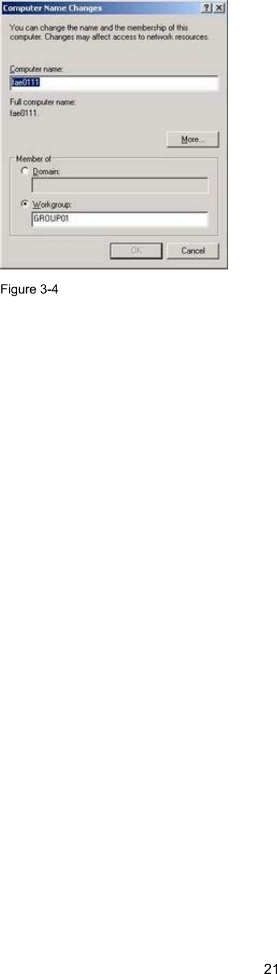
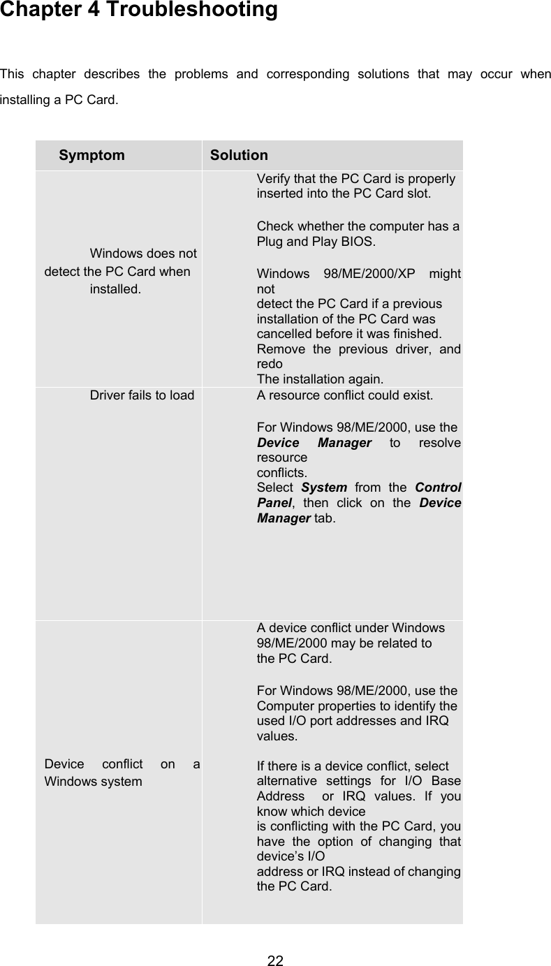
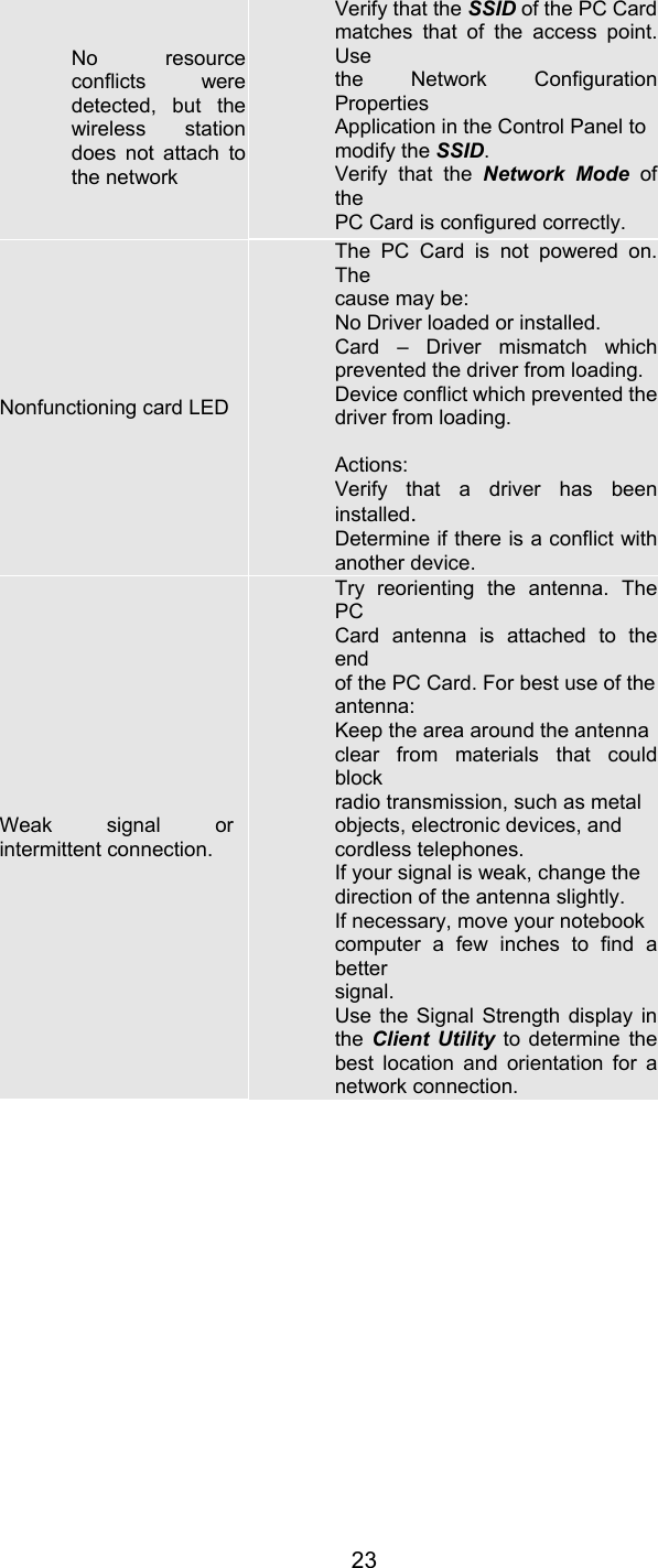
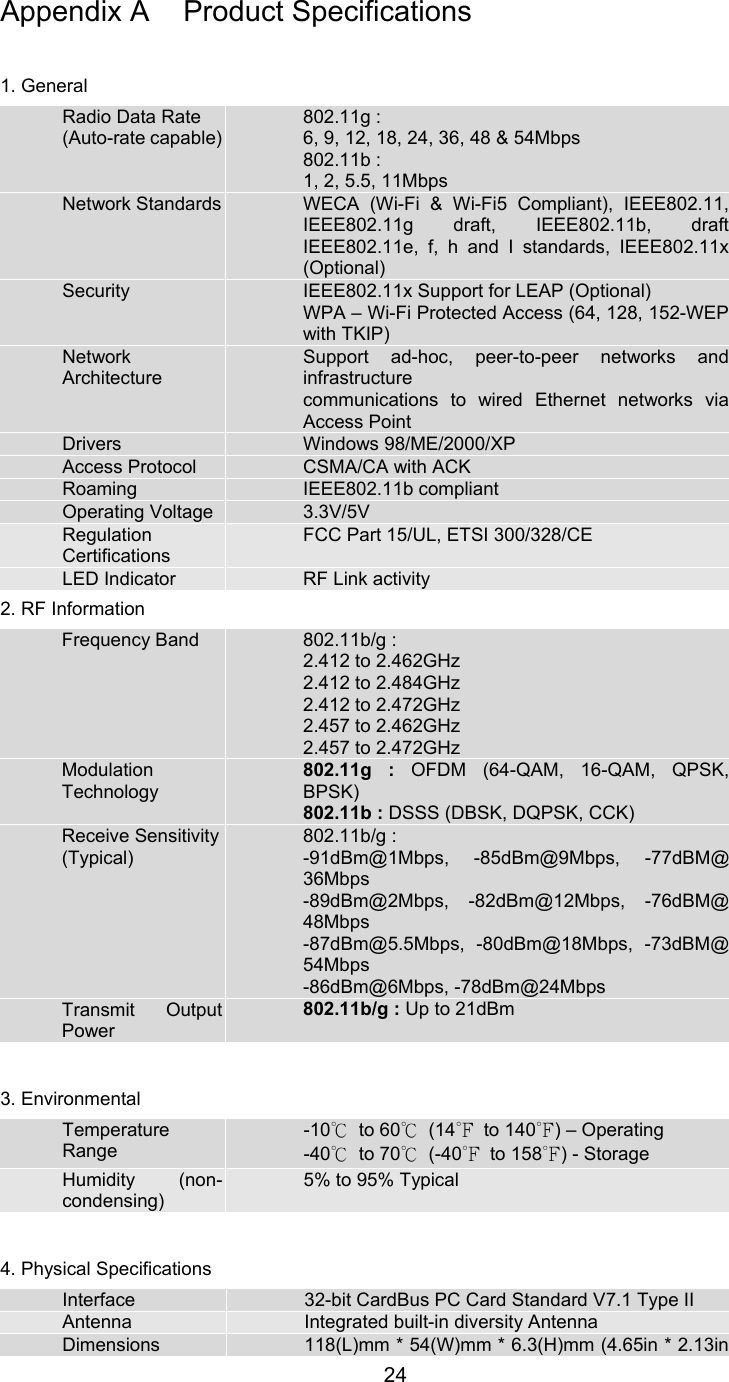
User Manual
Discussion / Help
Navigation