Senao Co AT30V514 802.11g Cardbus Adapter User Manual Draft WPC 3007 User Manual
Senao International Co Ltd 802.11g Cardbus Adapter Draft WPC 3007 User Manual
UserManual.wiki
>
Senao Co
>
AT30V514 User Manual
>
Users Manual Revision 3
Contents
1.
DoC
2.
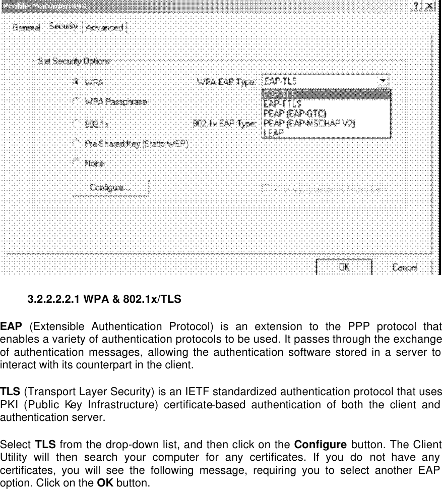
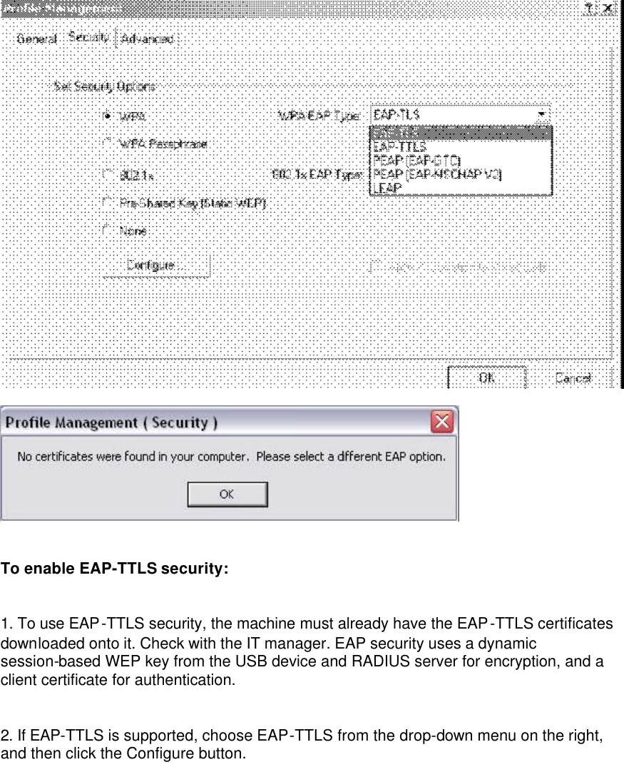
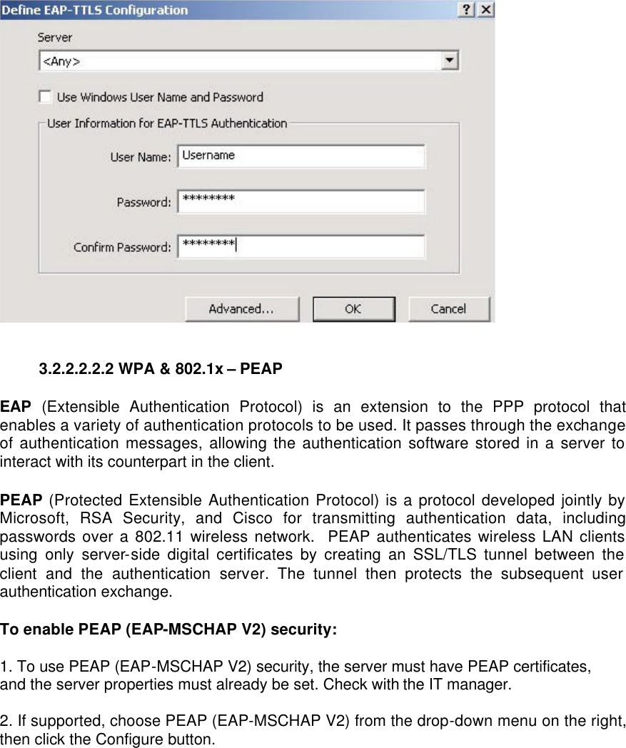
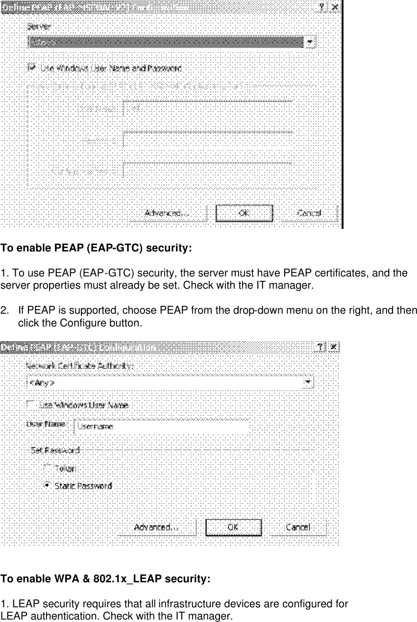
Users Manual Revision 3
Users Manual Revision 3
Navigation menu
Upload a User Manual
Namespaces
Wiki Guide
HTML
PDF
Info
Views
User Manual
Discussion / Help
Navigation