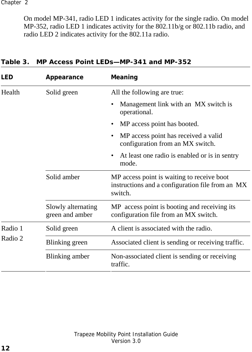
Senao Co AT53MP52 WIRELESS AP User Manual mp install1
Senao International Co Ltd WIRELESS AP mp install1
UserManual.wiki
>
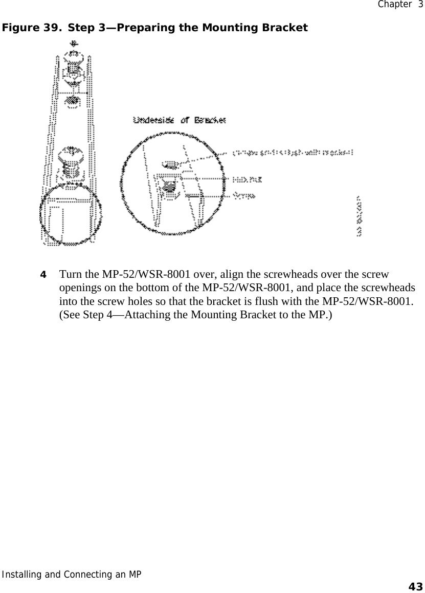
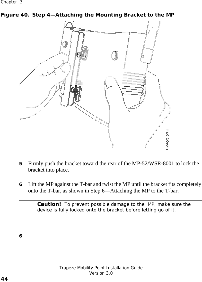
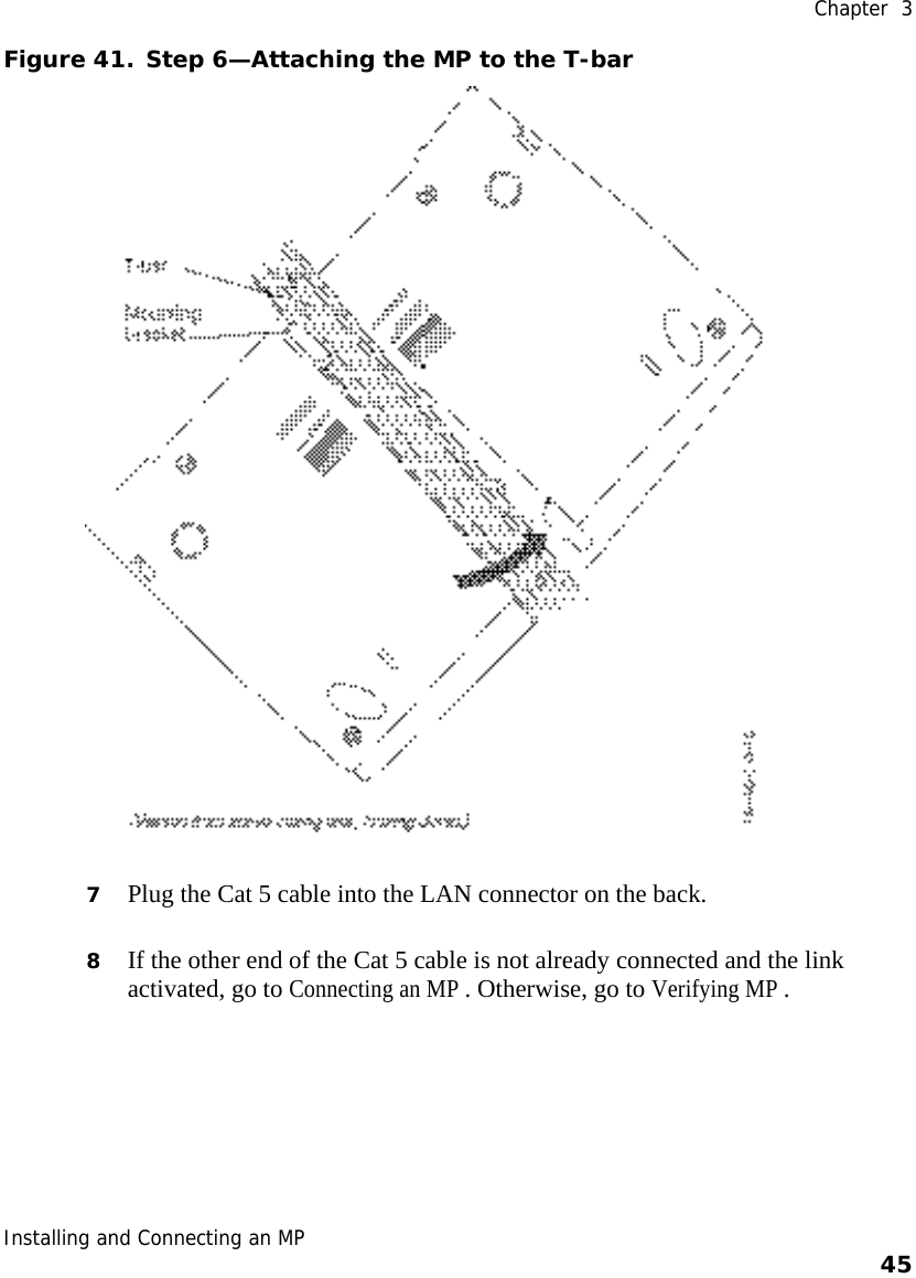
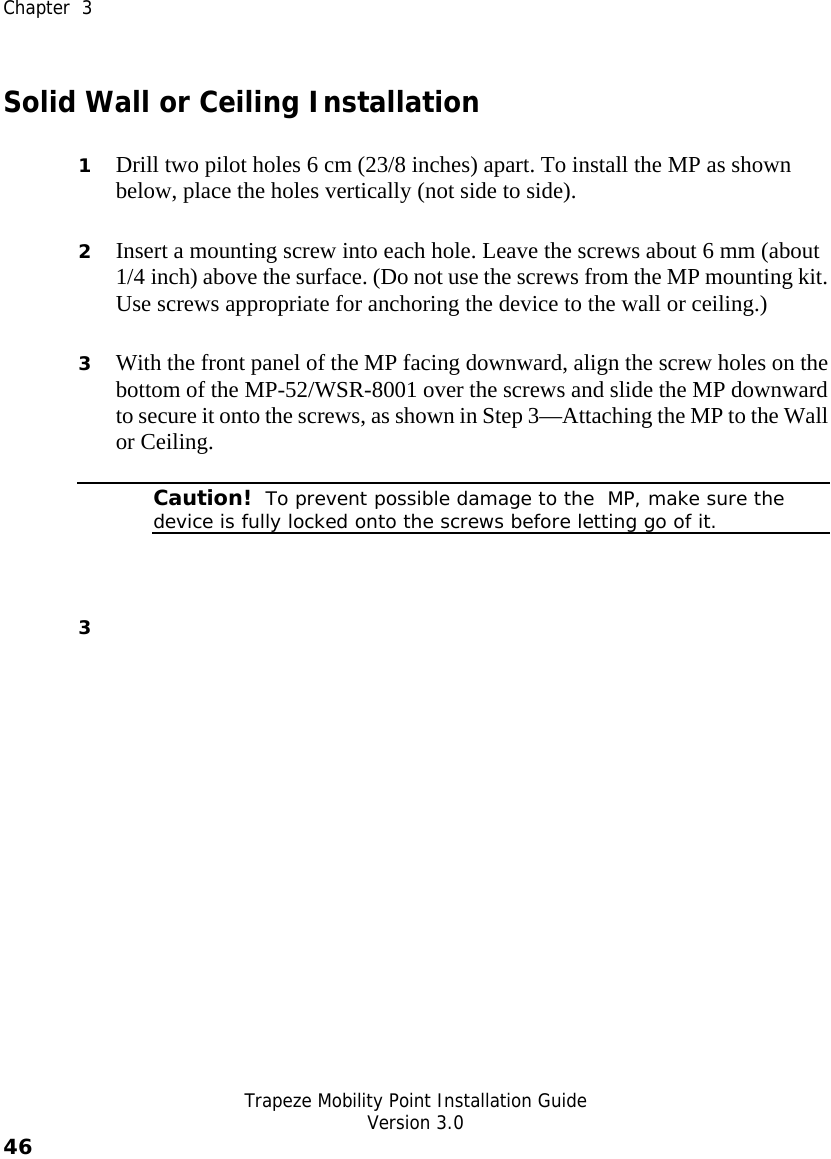
Senao Co
>
AT53MP52 User Manual
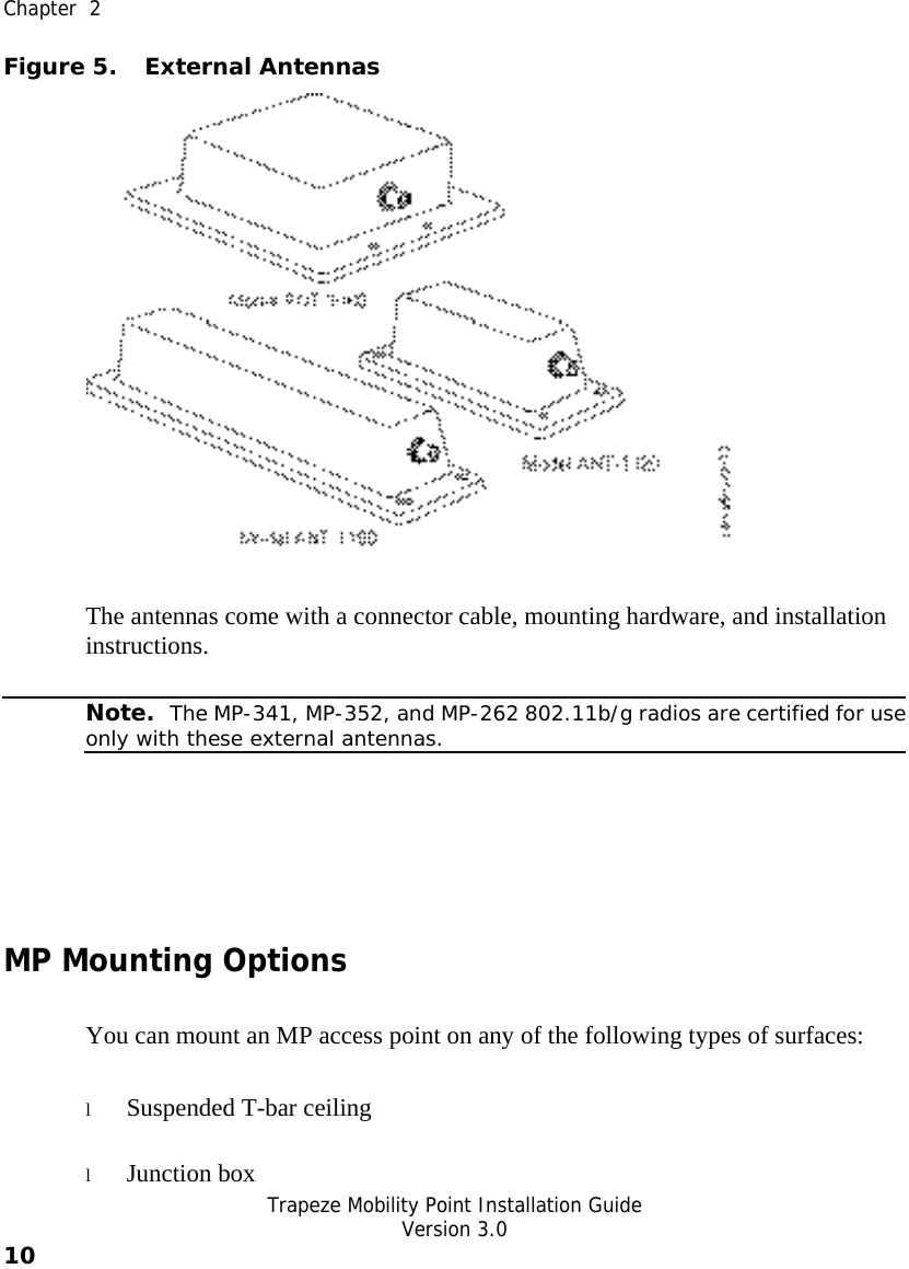
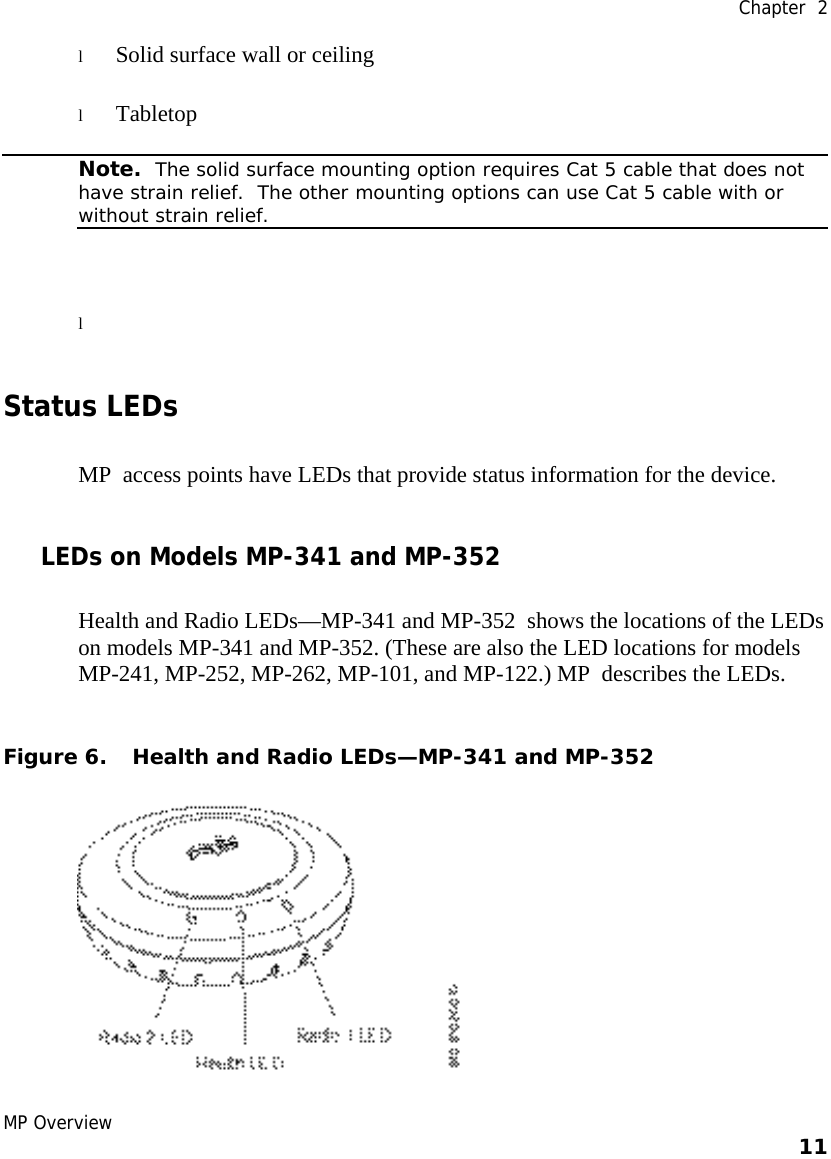
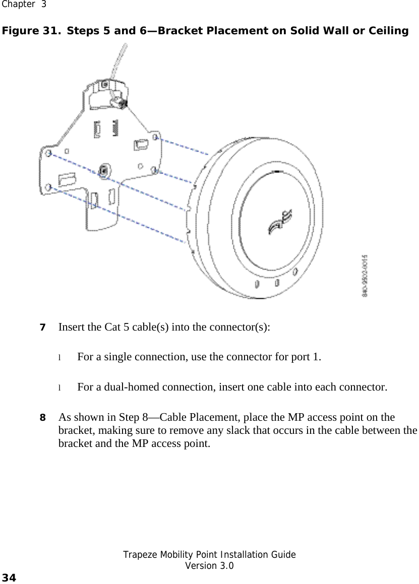
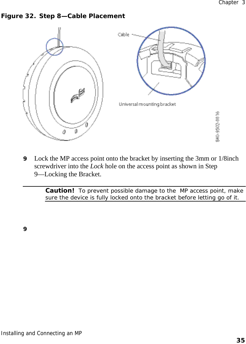
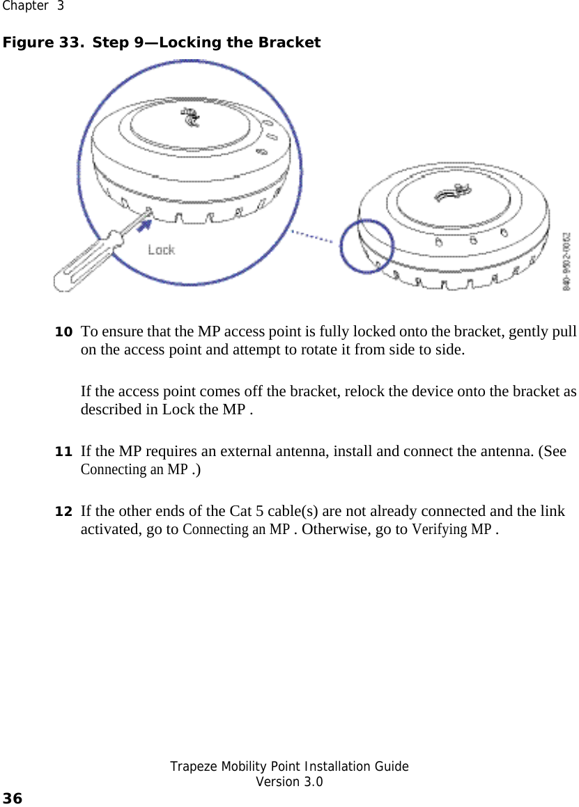
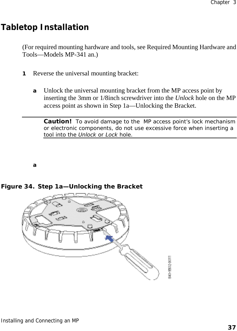
Users Manual
Navigation menu
Upload a User Manual
Namespaces
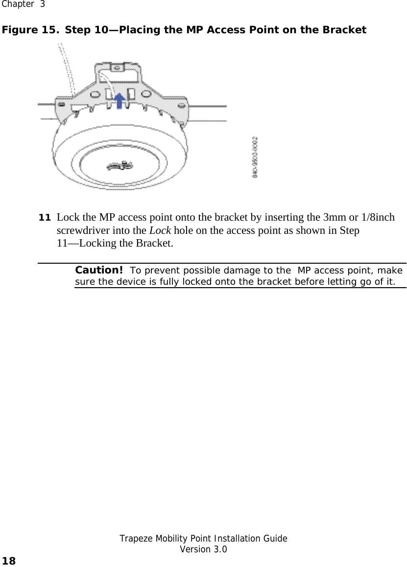
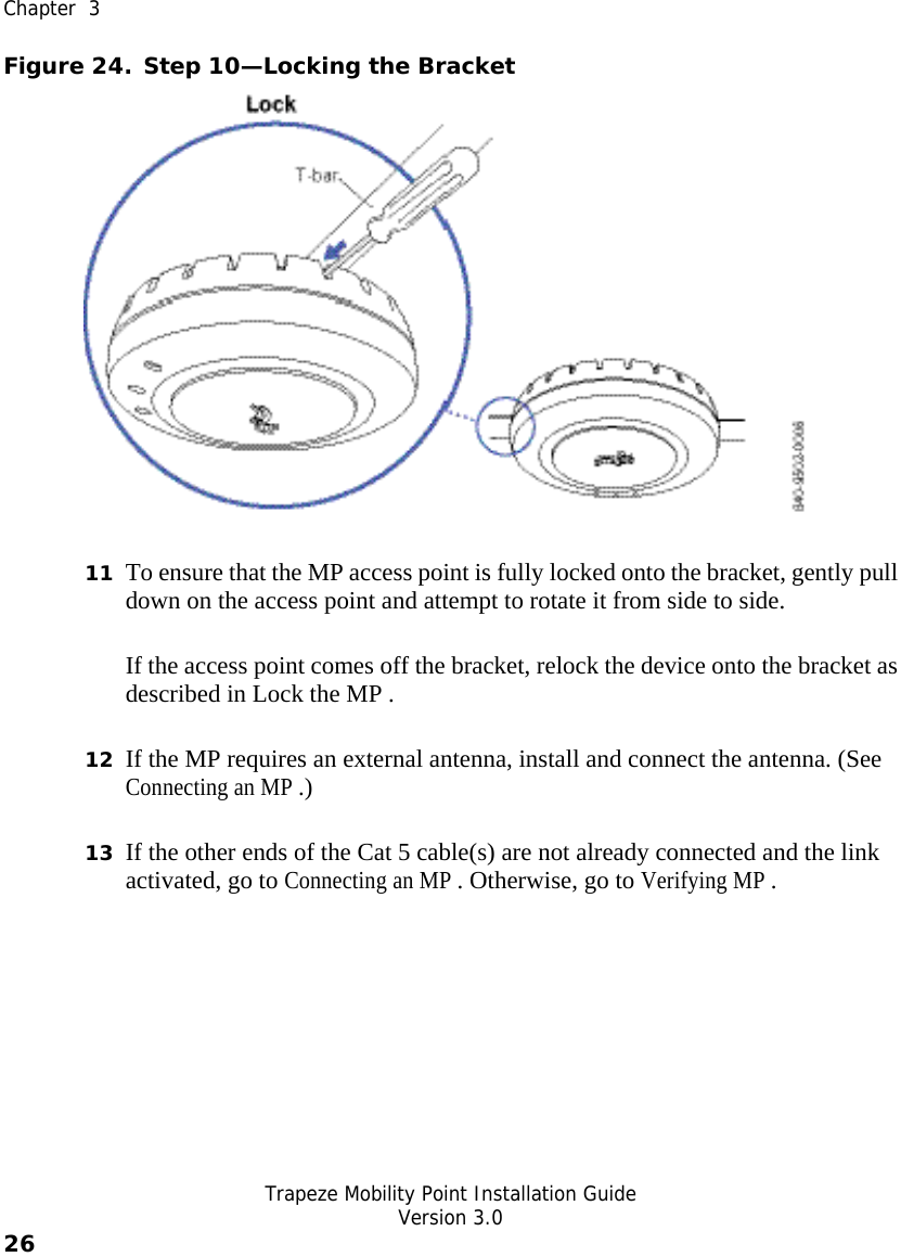
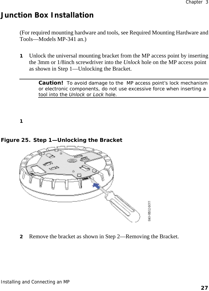
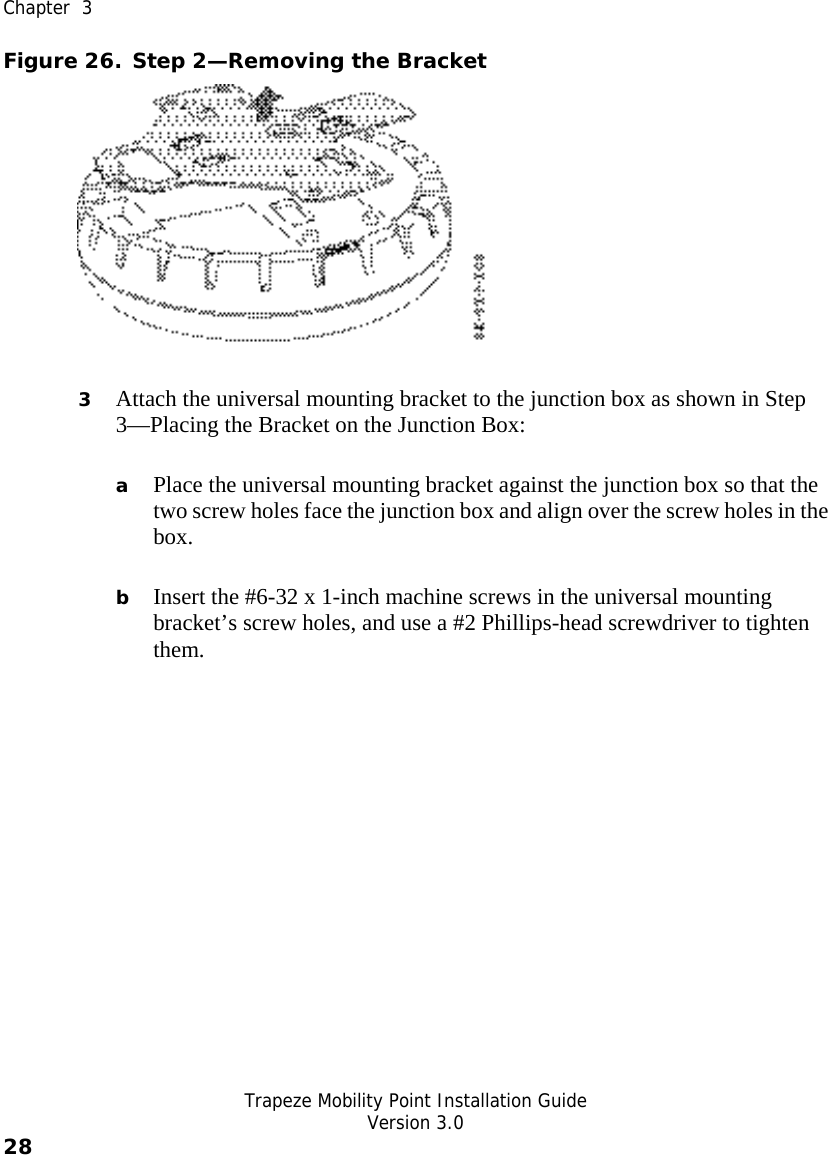
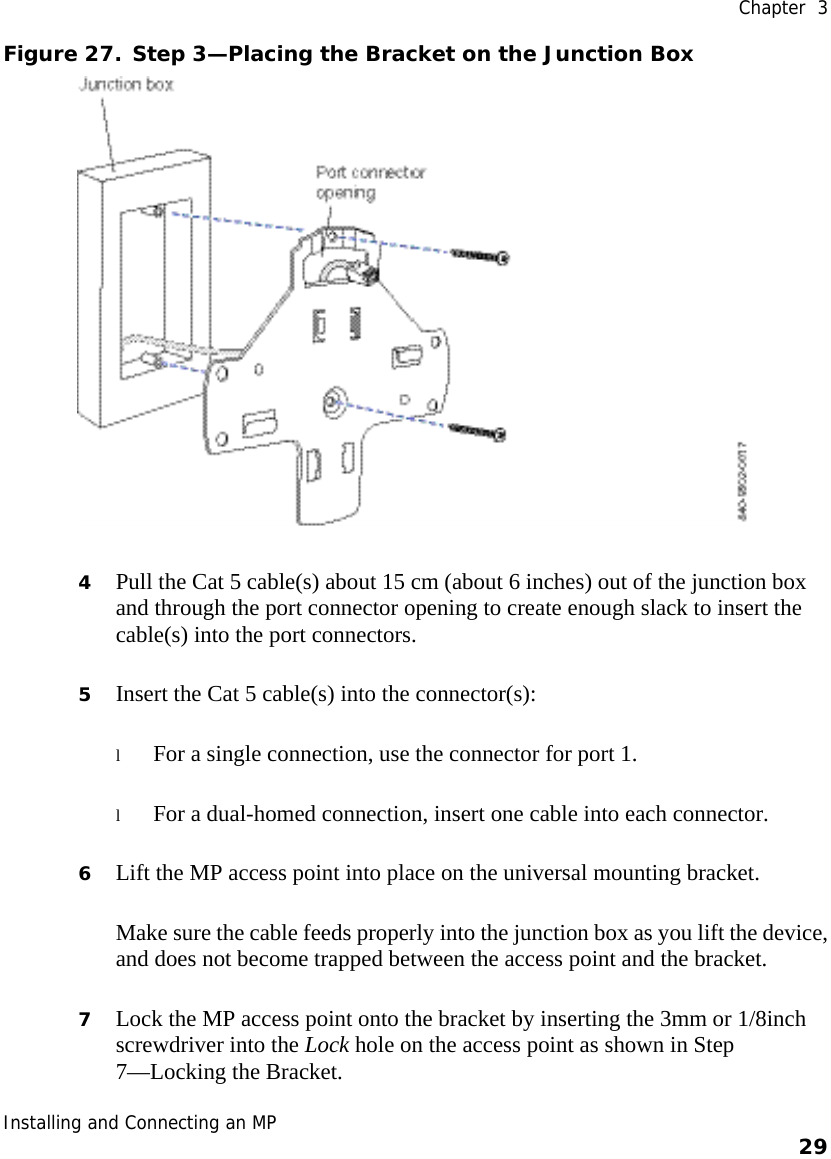
Wiki Guide
HTML
PDF
Info
Views
User Manual
Discussion / Help
Navigation
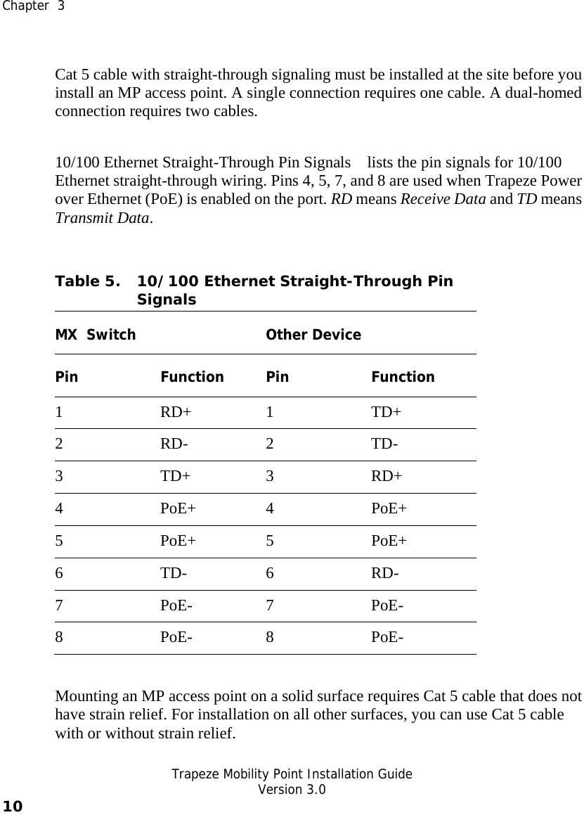
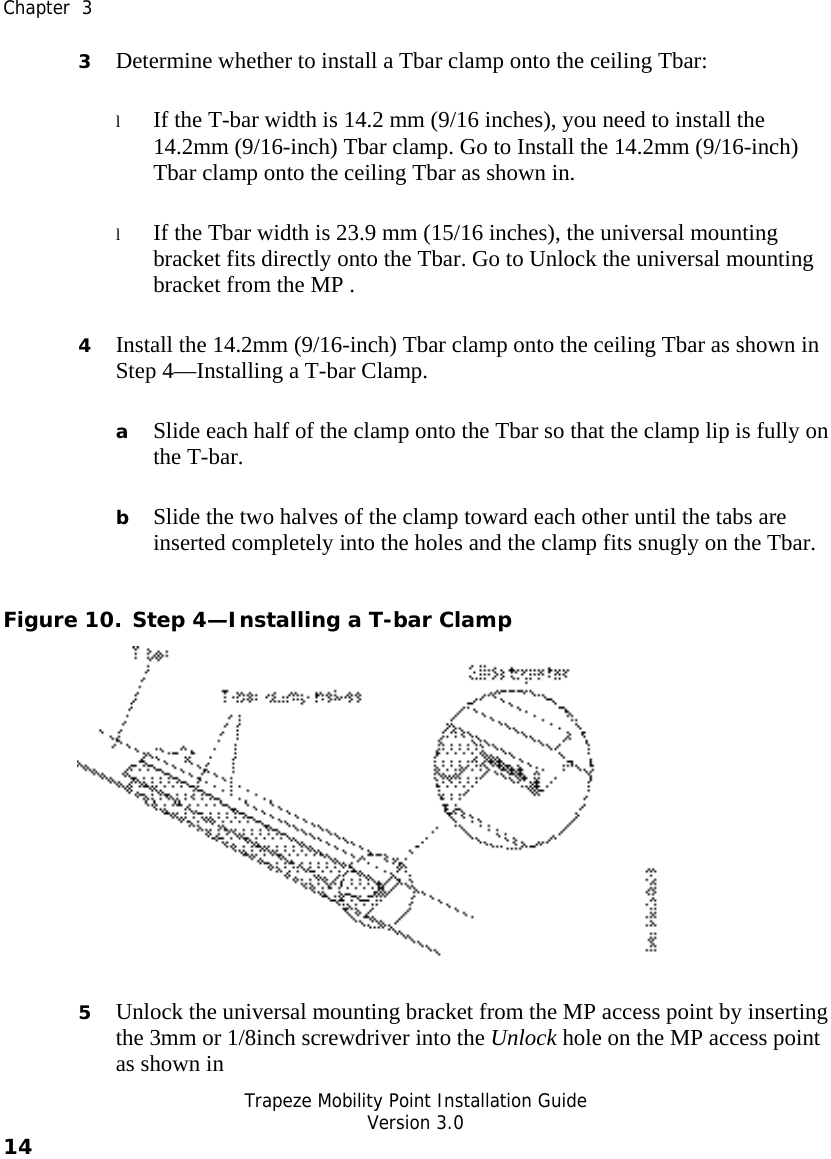
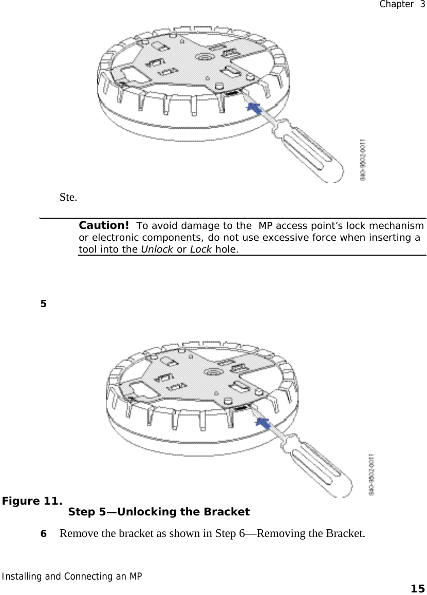
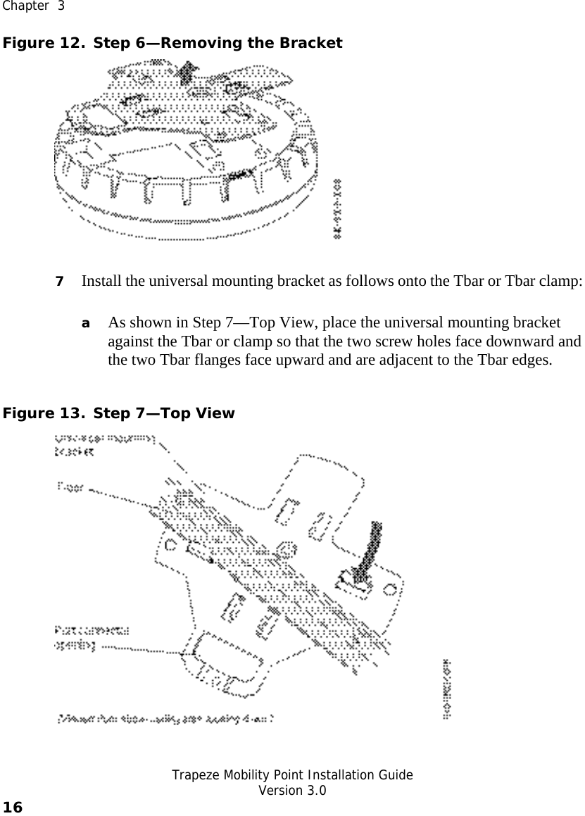
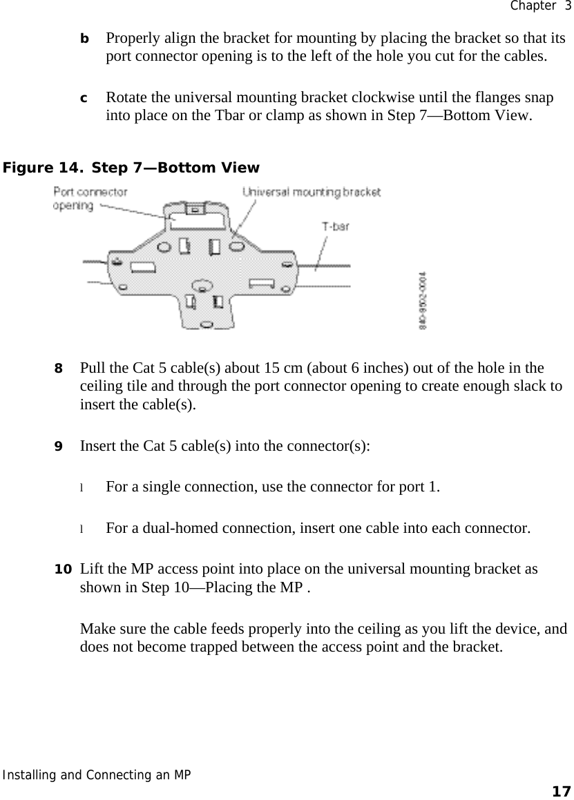
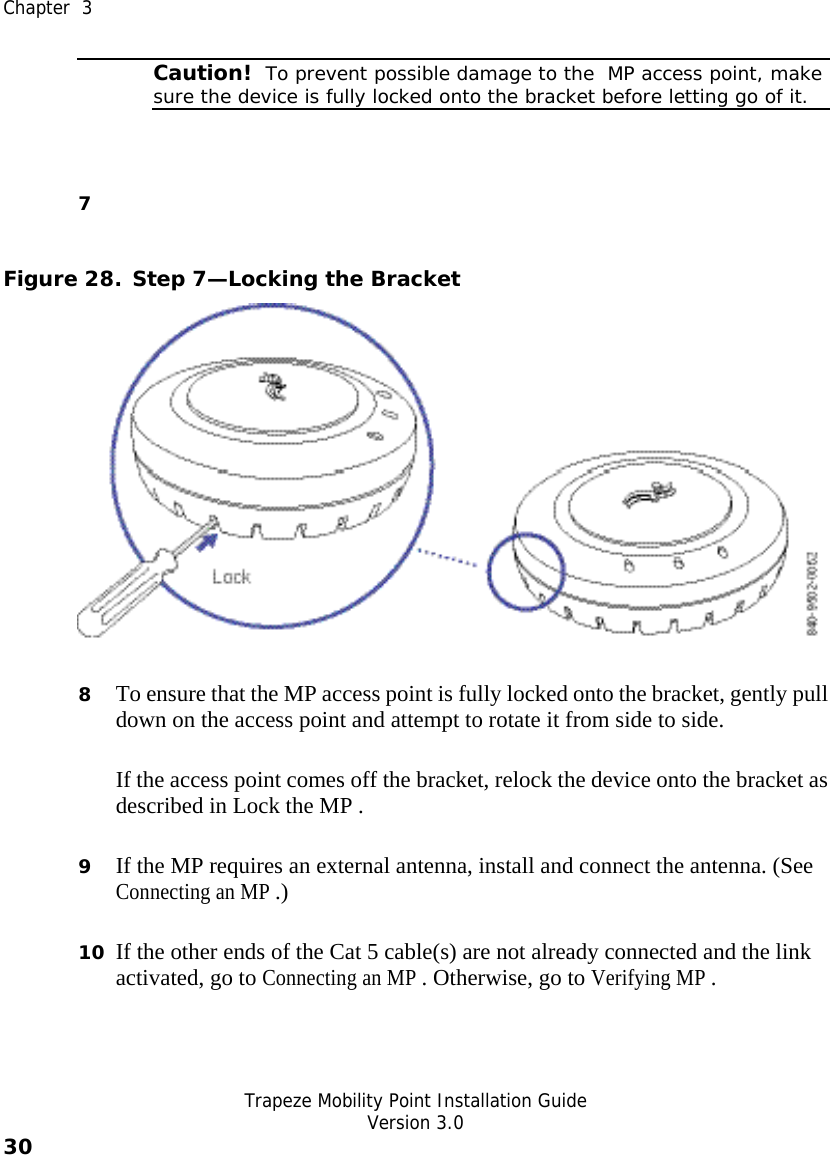
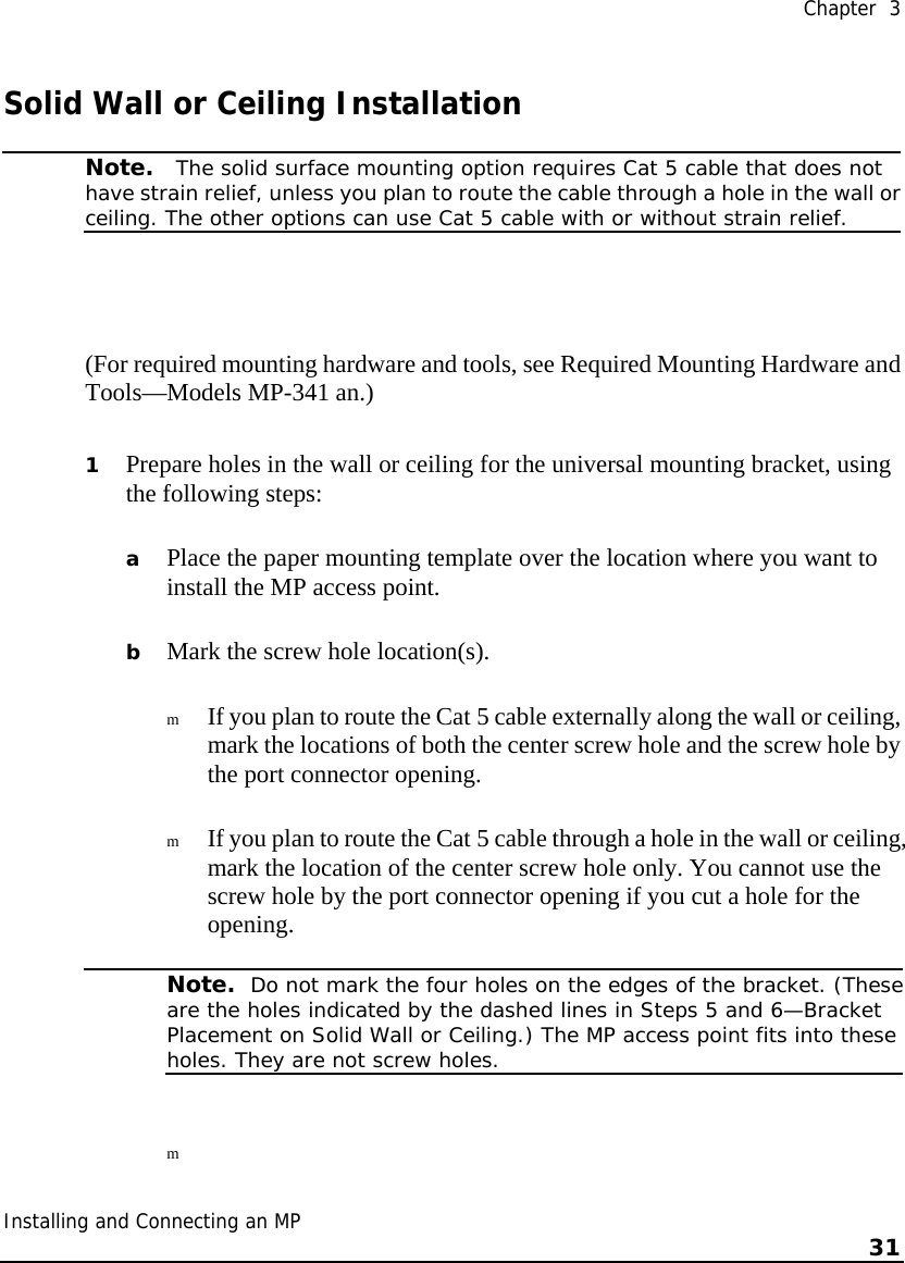
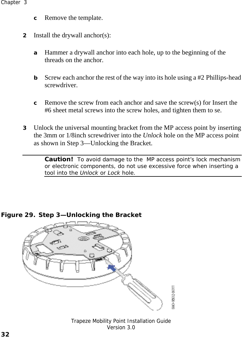
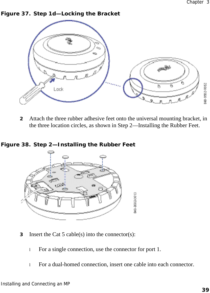
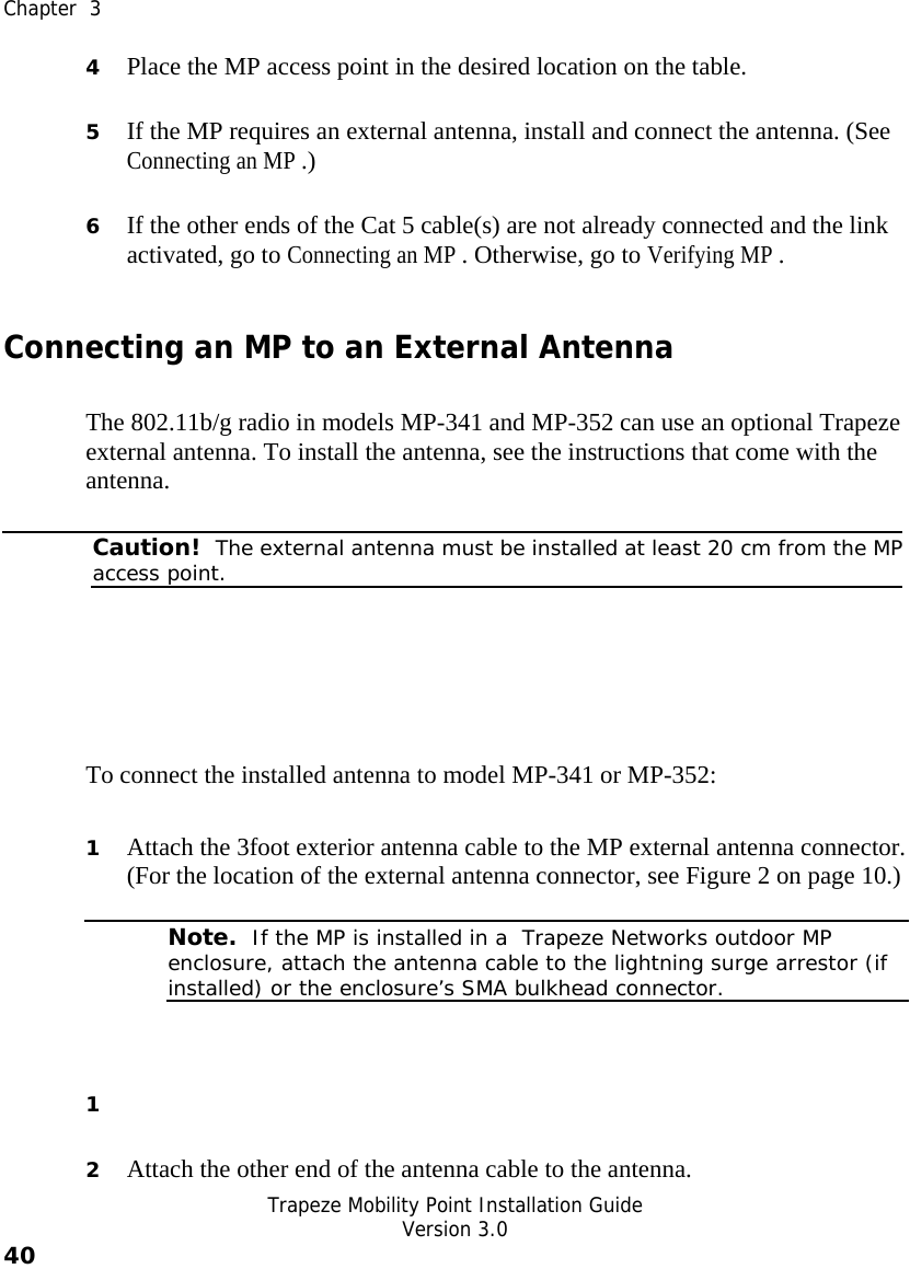
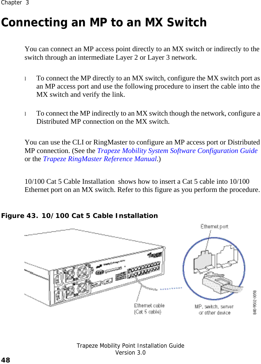
![Trapeze Networks MobChapter 1 Introducing the Trapeze Networks Mobility System 5 Warning! Radiation. This situation or condition can cause injury due to improper handling of fiber-optic equipment. Note. This information is of special interest. Text and Syntax Conventions Trapeze manuals use the following text and syntax conventions: Convention Use Monospace text Sets off command syntax or sample commands and system responses. Bold text Highlights commands that you enter or items you select. Italic text Designates command variables that you replace with appropriate values, or highlights publication titles or words requiring special emphasis. Menu Name > Command Indicates a menu item that you select. For example, File > New indicates that you select New from the File menu. [ ] (square brackets) Enclose optional parameters in command syntax. { } (curly brackets) Enclose mandatory parameters in command syntax.](https://usermanual.wiki/Senao-Co/AT53MP52/User-Guide-483882-Page-12.png)